

Page 1

Intel® Stratix® 10 Device Security
User Guide
Updated for Intel® Quartus® Prime Design Suite: 19.1
Subscribe
Send Feedback
UG-S10SECURITY | 2019.05.10
Latest document on the web: PDF | HTML
Page 2

Contents
Contents
1. Intel® Stratix® 10 Device Security Overview...................................................................4
1.1. Intel Stratix 10 Secure Device Manager (SDM).......................................................... 6
1.2. Intel Stratix 10 Base Security..................................................................................7
1.2.1. Side Channel Resistance............................................................................. 7
1.3. Owner Security Keys and Programming.................................................................... 8
1.3.1. eFuse (Volatile or Non-Volatile) AES Root Key................................................8
1.3.2. BBRAM (Volatile) AES Root Key....................................................................8
2. Design Authentication.....................................................................................................9
2.1. The Configuration Bitstream ...................................................................................9
2.2. Signature Block................................................................................................... 11
2.2.1. Authentication for HPS Software................................................................ 13
3. Using the Authentication Feature..................................................................................14
3.1. Step 1: Creating the Root Key............................................................................... 15
3.2. Step 2: Creating the Design Signing Key.................................................................15
3.3. Step 3: Appending the Design Signature Key to the Signature Chain...........................16
3.4. Step 4: Signing the Bitstream................................................................................17
3.4.1. Step 4a: Signing the Bitstream Using the Programming File Generator............17
3.4.2. Step 4b: Signing the Bitstream Using the quartus_sign Command.................. 19
3.5. Step 5: Programming the Owner Public Root Key for Authentication............................20
3.5.1. Step 5a: Programming the Owner Public Root Key Using the Intel Quartus
Prime Programmer................................................................................... 20
3.5.2. Step 5b: Calculating the Owner Public Root Key Hash................................... 22
4. Co-Signing Device Firmware Overview..........................................................................23
4.1. Using the Co-Signing Feature................................................................................ 23
4.1.1. Prerequisites for Co-Signing Device Firmware.............................................. 24
4.1.2. Generating the Owner Firmware Signing Key............................................... 24
4.1.3. Co-Signing the Firmware ..........................................................................25
4.1.4. Programming the Co-Signed Firmware eFuses .............................................25
4.1.5. Powering On In JTAG Mode After Implementing Co-Signed Firmware...............27
4.1.6. Canceling Intel Firmware ID...................................................................... 27
5. Signing Command Detailed Description........................................................................ 30
5.1. Generate Private PEM Key..................................................................................... 31
5.2. Generate Public PEM Key.......................................................................................31
5.3. Generate Root Signature Chain..............................................................................31
5.4. Append Key to Signature Chain..............................................................................31
5.5. Sign the Bitstream............................................................................................... 32
5.6. Calculate Public Root Key Hash from QKY................................................................33
6. Encryption and Decryption Overview............................................................................ 34
6.1. Using the Encryption Feature.................................................................................35
6.1.1. Step 1: Preparing the Owner Image and AES Key File................................... 36
6.1.2. Step 2a: Generating Programming Files Using the Programming File
Generator............................................................................................... 36
6.1.3. Step 2b: Generating Programming Files Using the Command Line Interface .... 38
Intel® Stratix® 10 Device Security User Guide
2
Send Feedback
Page 3

Contents
6.1.4. Step 3a: Specifying Keys and Configuring the Encrypted Image Using the
Intel Quartus Prime Programmer ...............................................................38
6.1.5. Step 3b: Programming the AES Key and Configuring the Encrypted Image
Using the Command Line.......................................................................... 40
7. Using eFuses ................................................................................................................ 41
7.1. Fuse Programming Input Files............................................................................... 43
7.1.1. Fuse File Format...................................................................................... 44
8. Document Revision History for Intel Stratix 10 Device Security User Guide..................45
Send Feedback
Intel® Stratix® 10 Device Security User Guide
3
Page 4

UG-S10SECURITY | 2019.05.10
Send Feedback
1. Intel® Stratix® 10 Device Security Overview
Intel® Stratix® 10 devices provide flexible and robust security features to protect
sensitive data, intellectual property, and the device itself under both remote and
physical attacks.
Intel Stratix 10 devices provide two main categories of security features:
authentication and encryption.
Authentication ensures that both the firmware and the configuration bitstream are
from a trusted source. Authentication is fundamental to Intel Stratix 10 security. You
cannot enable any other Intel Stratix 10 security features without enabling owner
authentication. Integrity checking which is part of authentication prevents accidental
bitstream change, corruption, or malicious attack.
Encryption prevents theft of intellectual property. Encryption protects confidential
information in the owner configuration bitstream.
Here are the specific security features that Intel Stratix 10 devices provide:
Authentication Category
• Elliptic Curve Based Public-Key Authentication: This feature allows the device to
authenticate Intel firmware and the configuration bitstream. Intel Stratix 10
devices always require firmware authentication for all Intel firmware that loads
into silicon. This requirement ensures that Intel is the only source that provides
the primary firmware for the Secure Device Manager (SDM) and most other
firmware that runs on other configuration processors in the Intel Stratix 10 device.
Intel Stratix 10 devices do not require authentication for the owner configuration
bitstream. You enable authentication for your configuration bitstream through
eFuse settings. After you program the hash of the root public key into eFuses, the
Intel Stratix 10 device only accepts an owner configuration bitstream that is
signed with corresponding private signing key.
• Anti-tampering security feature: Anti-tampering addresses physical attacks on
silicon. There are two categories of anti-tampering features: passive and active
anti-tampering.
— The passive anti-tampering feature enforces physical security features using
redundancy and interlocking systems. Passive anti-tampering is always
running on Intel Stratix 10 devices. Passive anti-tampering functions do not
operate in response to a particular function.
— Active anti-tampering responds when the silicon detects physical attacks from
the outside. By default, all active anti-tampering functions are off. When the
active anti-tampering function is on, you can select which detection functions
and responses to enable.
Intel Corporation. All rights reserved. Agilex, Altera, Arria, Cyclone, Enpirion, Intel, the Intel logo, MAX, Nios,
Quartus and Stratix words and logos are trademarks of Intel Corporation or its subsidiaries in the U.S. and/or
other countries. Intel warrants performance of its FPGA and semiconductor products to current specifications in
accordance with Intel's standard warranty, but reserves the right to make changes to any products and services
at any time without notice. Intel assumes no responsibility or liability arising out of the application or use of any
information, product, or service described herein except as expressly agreed to in writing by Intel. Intel
customers are advised to obtain the latest version of device specifications before relying on any published
information and before placing orders for products or services.
*Other names and brands may be claimed as the property of others.
ISO
9001:2015
Registered
Page 5

®
1. Intel
UG-S10SECURITY | 2019.05.10
Stratix® 10 Device Security Overview
Encryption Category
• Advanced Encryption Standard (AES)-256 encryption: This feature protects the
owner configuration bitstream intellectual property (IP) or confidential data as part
of root security in the owner configuration bitstream. AES-CTR (counter) mode is
the base for bitstream encryption. To reduce AES key exposure from random
attacks, AES decryption only operates on data that has already passed public key
authentication.
• Side channel protection: Side channel protection prevents AES Key and
confidential data under non-intrusive attack. Intel Stratix 10 devices include the
following functions to protect side channel leakage from silicon.
— A key update function protects the AES keys in bitstream decryption.
— The authentication first flow protects against unnecessary key exposure.
— Long route data line scrambling protects against side channel leakage over
data lines.
— A 256-bit wide direct key bus loading limits unauthorized access to keys.
— Key scrambling in the key vault protects key values.
• Multiple AES root key choices: Intel Stratix 10 devices support three different
types of root AES keys: eFuse, BBRAM, and physically unclonable function (PUF).
• Black key provisioning: Key provisioning, especially secret key provisioning, is
costly. In addition, key provisioning is the least secure step in the encryption
process. Black key provisioning creates a direct secure channel between your
custom hardware security module (HSM) and the Intel Stratix 10 device for key
provisioning. Having a secure channel ensures confidential information including
the AES key are provisioned into silicon without exposure to an intermediate party.
As a side benefit, black key provisioning also helps secure the supply chain at
contract manufacturing facilities.
Note: These security features are available in Intel Stratix 10 devices that support advanced
security. The ordering codes for Intel Stratix 10 devices that include advanced security
features includes the AS (Advanced Security) suffix. Please contact your Intel
Programmable Solutions representative to get additional information about Intel
Stratix 10 device security features.
Related Information
Intel Quartus® Prime Pro Edition User Guide Programmer
Describes operation of the Intel Quartus® Prime Pro Edition Programmer, which
allows you to configure Intel FPGA devices, and program CPLD and configuration
devices, via connection with an Intel FPGA download cable.
Send Feedback
Intel® Stratix® 10 Device Security User Guide
5
Page 6

Configuration
Sector
Configuration
Sector
Configurable Network Interface
SDM Pins
Secure Device Manager
Dual Purpose I/O
Intel Stratix 10 FPGA
Intel Stratix 10 SX Blocks
Intel Stratix 10 GX Blocks
Intel Stratix 10 TX Blocks
Intel Stratix 10 MX Blocks
Additional blocks in the
Intel Stratix 10 device variants:
SX: Includes Hard Processor System
MX: Includes High-Bandwidth Memory
TX: Includes High-Bandwidth XCVRs
GX: General Purpose FPGA
Configuration
Sector
Configuration
Sector
Configuration Network
Local Sector
Manager (LSM)
Local Sector
Manager (LSM)
Local Sector
Manager (LSM)
Local Sector
Manager (LSM)
®
1. Intel
Stratix® 10 Device Security Overview
1.1. Intel Stratix 10 Secure Device Manager (SDM)
The Secure Device Manager (SDM) is a triple-redundant processor-based module that
manages the configuration and security features of Intel Stratix 10 devices. The SDM
authenticates and decrypts configuration data.
Figure 1. Secure Device Manager
UG-S10SECURITY | 2019.05.10
Authentication includes the following steps:
1. First, the SDM performs an integrity check using SHA-256 or SHA-384. The
integrity check ensures that the bitstream is not corrupted due to an accidental
occurrence such as a bad write to flash.
2. Then, the authentication process guarantees that a trusted source, the device
owner, created the configuration bitstream.
3. If successful, and you have enabled AES Encryption, the SDM then decrypts the
data. The SDM drives the decrypted data on the configuration network to Local
Sector Managers (LSM) on the configuration network. Each LSM parses the sector
configuration block data and configures the logic elements in the sector that it
manages.
Related Information
Intel Stratix 10 Configuration User Guide: Secure Device Manager
Intel® Stratix® 10 Device Security User Guide
6
Send Feedback
Page 7

®
1. Intel
UG-S10SECURITY | 2019.05.10
Stratix® 10 Device Security Overview
1.2. Intel Stratix 10 Base Security
To enable base security features, you must program the hash of the owner public root
key eFuse into Intel Stratix 10. As soon as you program the owner root key you have
created an Intel Stratix 10 device with basic security. Your configuration bitstream
must be signed.
Note: The fusing process automatically computes the hash of the owner public root key.
When you program the owner public root key, the programmer automatically
programs the hash value, not the full key.
You can enable the following additional security options to further enhance the
security level:
• Advanced Encryption Standard (AES) Encryption protects your IP and secures your
data. This option includes multiple sub-options relating to side channel mitigation.
• Configuration firmware joint signature capability allows you to sign the version of
configuration firmware to run on your device. At all times, the device only loads
firmware that Intel has authenticated. An eFuse on the Intel Stratix 10 device
enables this feature.
eFuse programming sets a minimum-security strength. All eFuse enforced security
options are permanent. In contrast to permanent security features, Intel Stratix 10
devices include some dynamic security options that you can control without using
eFuses. JTAG Secure is one example of a dynamic security feature. Intel Stratix 10
devices control dynamic security options by setting optional fields in the configuration
bitstream. Intel recommends using the optional fields in the configuration bitstream to
enforce security options when available. The optional fields provide a similar security
level as the eFuse setting with more flexibility.
1.2.1. Side Channel Resistance
Side channel resistance technology helps prevent secret leakage from the
Intel Stratix 10 device. Side channel mitigation is not limited to the AES engine. Any
circuit which could transport secret key material has its associated mitigation. Long
data transmission lines in silicon also implement security control agreement
mitigation.
The following side channel mitigation features are available in Intel Stratix 10 devices:
• AES side channel mitigation
— Key update: Limits to the amount of data encrypted by each key. The default
limit each key can encrypt is 4 KB.
— Authentication first: The device authenticates the bitstream before decrypting
it. Attackers cannot perform differential attacks on the AES before breaking
authentication.
• Datapath random number scrambling
• Physically unclonable function (PUF) enrollment and extraction scrambling
• 256-bit point-to-point Key bus
Send Feedback
Intel® Stratix® 10 Device Security User Guide
7
Page 8

®
1. Intel
Stratix® 10 Device Security Overview
UG-S10SECURITY | 2019.05.10
1.3. Owner Security Keys and Programming
Intel Stratix 10 devices support two types of security keys:
• Owner public root key hash: Programming this key enables the base security
features. The Intel Stratix 10 stores the SHA-256 or SHA-384 hash of this key in
eFuses or virtual eFuses. This key authenticates the final owner design signing key
through the public signature chain.
• Owner AES key: This optional key decrypts the encrypted owner image during the
configuration process. You can store the AES key in virtual or physical eFuses, a
BBRAM, or a PUF. You program the AES key using JTAG. The configuration
bitstream specifies the owner AES key location. For extra security, you can
program fuses to enforce eFuse key selection. For example, if your design stores
the AES key in eFuses, you can disable the BBRAM root key fuse for additional
security. Intel Stratix 10 devices support both red key (unencrypted) and black
key (encrypted) programming.
Note: You program or blow eFuses by flowing a large current for a specific amount of time.
This process is irreversible.
1.3.1. eFuse (Volatile or Non-Volatile) AES Root Key
Virtual eFuses are volatile. Physical eFuses are non-volatile. Once you program the
physical eFuse key, you cannot change or reprogram the key. The value stored in
eFuses is a device-unique scrambled version of the original owner key.
The Intel Quartus® Prime Programmer includes a Device security key storage
option. This option is available for Intel Stratix 10 and later devices that include the
SDM when you program a Intel Quartus Prime encryption key .qek.
Note: The current release only support the battery-backed RAM (BBRAM) storage location.
1.3.2. BBRAM (Volatile) AES Root Key
In contrast to eFuse keys, BBRAM keys are reprogrammable. The BBRAM key vault
holds a single key. Programming a new key deletes the previously programmed key.
The BBRAM key vault includes a built-in function to perform periodic key flipping to
prevent key imprinting.
The BBRAM AES key has its own power supply. V
The allowed voltage range is 1.2V - 1.8V.
Related Information
Recommended Operating Conditions for V
in Stratix 10 Device Datasheet
CCBAT
powers the BBRAM AES key.
CCBAT
Intel® Stratix® 10 Device Security User Guide
8
Send Feedback
Page 9

UG-S10SECURITY | 2019.05.10
Send Feedback
2. Design Authentication
For networked systems, every power up or remote system upgrade to an
unauthenticated bitstream is vulnerable to attack. Malicious attacks can occur because
the FPGA does not verify that configuration bitstream is from a trusted source. Intel
Stratix 10 FPGAs include a feature to authenticate the bitstream, guaranteeing that
the bitstream is from a trusted source. Authentication uses signature keys to validate
the content of a bitstream, preventing the Intel Stratix 10 FPGA from configuring with
an unauthorized configuration bitstream.
When you use authentication, your manufacturing process programs the hash digest
of the Elliptic Curve Digital Signature Algorithm (ECDSA) public signature key into
FPGA eFuses. The configuration bitstream contains the public signature key. The SDM
compares the hash digest of configuration bitstream public signature key to the hash
digest stored in eFuses. The SDM only loads the bitstream if the values match.
You can choose either ECDSA256 or ECDSA384. The ECDSA256 and ECDSA384 use
the SHA-256 and SHA-384 cryptographic hash function to create the secure hash.
Intel recommends that you use 384-bit algorithm. The 256-bit algorithm is weaker
than the algorithm and consequently more likely to become vulnerable to attack. Use
the 256-bit algorithm if you have a custom hardware security module (HSM) that does
not accept SHA-384 hashes. SHA-384 generates a bitstream that is larger than
SHA-256. SHA-384 hashes result in longer configuration times.
2.1. The Configuration Bitstream
The figure below shows an Intel Stratix 10 configuration bitstream that includes an
FPGA and HPS. The firmware section is static and is dependent on the Intel Quartus
Prime version.
The SDM always authenticates the firmware configuration bitstream whether you
choose to authenticate the other dynamic sections of the bitstream. To create an
additional level of security, you may request joint signing for the configuration
bitstream by programming the Joint Signature fuse on the device. When the Joint
Signature fuse is programmed, the device checks for an owner signature on the
firmware section of the configuration bitstream. The device only runs firmware with
both signatures.
Intel Corporation. All rights reserved. Agilex, Altera, Arria, Cyclone, Enpirion, Intel, the Intel logo, MAX, Nios,
Quartus and Stratix words and logos are trademarks of Intel Corporation or its subsidiaries in the U.S. and/or
other countries. Intel warrants performance of its FPGA and semiconductor products to current specifications in
accordance with Intel's standard warranty, but reserves the right to make changes to any products and services
at any time without notice. Intel assumes no responsibility or liability arising out of the application or use of any
information, product, or service described herein except as expressly agreed to in writing by Intel. Intel
customers are advised to obtain the latest version of device specifications before relying on any published
information and before placing orders for products or services.
*Other names and brands may be claimed as the property of others.
ISO
9001:2015
Registered
Page 10

Firmware Section
Firmware section
is static and
Quartus Prime
version dependent
Design Section
(IO Configuration)
Design Section
(FPGA Core Configuration)
Design Section
(HPS boot code)
Header Block
Hash for Hash Block 0
Hash in the
Header Block
validates
Hash Block 0
Hash and signature
over Header Block
Signature Block
Hash Block 0 (SHA-384 or SHA-256)
Data Block 0
Data Block 1
Data Block 83 or 125
Hash Block 1 (SHA-384 or SHA-256)
Data Block 83 or 125
Hash Block N
Data Block 0
Data Block 1
Hash Block 0
validates
Hash Block 1,
and so on
2. Design Authentication
UG-S10SECURITY | 2019.05.10
Figure 2. Example of an Intel Stratix 10 Configuration Bitstream Structure
The I/O, HPS, and FPGA sections are dynamic and contain the device configuration
information based on your design. Each dynamic section of the configuration bitstream
stores information in the same format. Each section begins with a 4 kilobyte (KB)
header block, followed by a signature block, hash blocks, and data.
Figure 3. Configuration Bitstream Layout
Intel® Stratix® 10 Device Security User Guide
10
Send Feedback
Page 11
SHA-384 hash over Header Block 1st Signature Chain
2nd Signature Chain
3rd Signature Chain
4th Signature Chain
Root Key
Public Key Entry 1 (Recommended)
Public Key Entry 2 (Optional)
Header Block Entry
Offset to signature chains
Up to 4 Signature Chains
Dynamic Sector Pointers
32-bit CRC
2. Design Authentication
UG-S10SECURITY | 2019.05.10
The header block contains a hash which validates hash block 0. Each hash block
contains up to 125 SHA-256 hashes or 83 SHA-384 hashes. These hashes validate
subsequent data blocks.
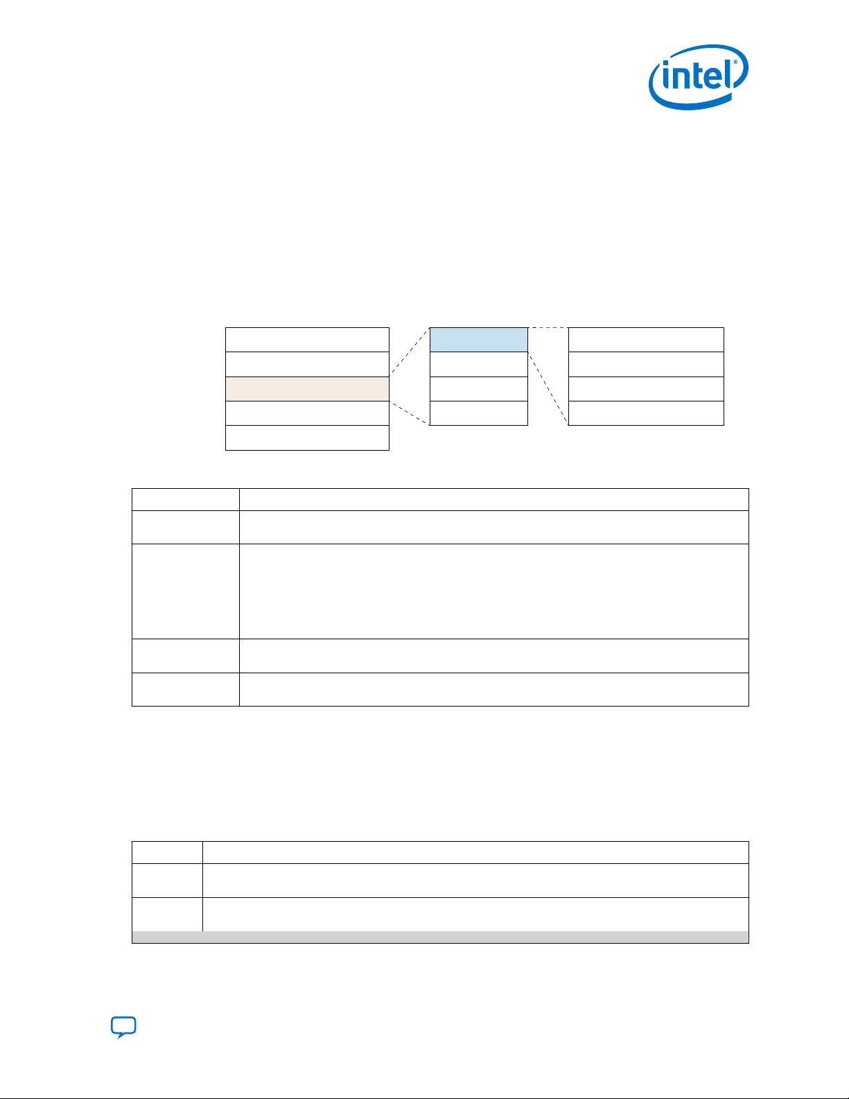
2.2. Signature Block
The signature block validates the contents of the header block. After successfully
validating the signatures, the SDM processes the data based on the signatures
provided.
Figure 4. Signature Block Format
Table 1. Signature Block
Block Description
SHA-384 hash of
header block
Signature chains Zero or more signature chains. Each signature chain can include up to 3 keys, including the owner
Dynamic sector
pointers
32-bit CRC Protects the block from accidental modification. The CRC does not provide security. Software tools
This hash function checks for accidental changes in the preceding block of the configuration
bitstream, typically the header block.
public root key. The other 2 keys support separate signatures for the firmware, core, and HPS
sections of the configuration bitstream.
The Intel Quartus Prime Software supports 2 keychains for control module firmware (CMF) signing
and up to 4 keychains for the configuration bitstream. Multiple keychains provide some flexibility. For
example, if you change your root key and want to create a design which works on devices with both
the old and new root key.
Locate the design sections for the remainder of the image when you store the image in flash
memory.
can check the CRC to identify accidental modifications.
Signature Chain Details
Intel Stratix 10 FPGAs support up to four signature chains. If a signature chain is
invalid, it is ignored. The FPGA starts validating the next signature chain. This
capability allows for root key rollover. To pass authentication, at least one signature
keychain must pass.
Table 2. Signature Chain Content
Content Description
Root Key
Entry
Public Key
Entry
The Root Entry anchors the chain to a root key known to the FPGA. The FPGA calculates the hash of the root
entry and checks if the it matches the expected hash. You store the root key in eFuses.
Signature chains enable flexible key management. Intel recommends one public key entry in each signature
chain. The previous public key signs the new public key. The public key entry provides following capabilities:
continued...
Send Feedback
Intel® Stratix® 10 Device Security User Guide
11
Page 12
Content Description
Create 1st Level
Signature Chain Signature Chain
Root Keychain
Permission = 4 (HPS, FSBL)
Cancellation ID = 33
Level Public Key
1
st
Permission = 2 (Core, I/O, PR)
Cancellation ID = 32
1st Level
Level Public Key
1
st
• Key bit fields to limit the areas a public key entry can sign. The following permissions values are valid:
— Bit 0: Firmware
— Bit 1: FPGA I/O, core sections, and PR sections
— Bit 2: HPS I/O and first stage bootloader sections (FSBL)
• If more than one bit field is on, the key can sign more than one section. For example, if both bits 1 and 2
are on, the key can sign the FPGA I/O, score, PR, HPS I/O, and FSBL sections of the design.
• Cancellation ID: Specifies the number that cancels a key that is no longer valid. Intel Stratix 10 devices
include 32 cancellation IDs. Cancellation IDs 0-31 cancel owner keys. Once you cancel a key, any
previous designs using the canceled key are unusable. You can use this feature to prevent older designs
from running on a device or as part of recovery from a compromised key. Firmware controls the order in
which eFuses are blown.
Second- or third-level keys typically sign data. Intel Stratix 10 devices support signature chains containing
up to three keys, including up to 2 public key entries.
Header
Block Entry
The final entry in a signature chain signs the actual data. The Block0 Entry authenticates the first block of
the section, and thus authenticates the whole section.
Understanding Permissions and Cancellation IDs
You use permissions to specify the sections that a key can sign. You can use the same
or different cancellation key for the different sections. If you use the same cancellation
ID for more than one section, canceling any section with that cancellation ID cancels
all sections using that cancellation ID. For example, if you assign the same
cancellation ID to both the FPGA and HPS sections, canceling the HPS section also
invalidates the FPGA section. The root signature key does not have a cancellation ID.
Consequently, you cannot cancel the root key. However, you can cancel a signature
chain that includes two or more signature levels. Intel strongly recommends that you
create a signature chain with at least two levels to retain the ability to update your
signature keychain. The following figure shows a signature chain with a root key and
two level one signature keys. The level one keys have different permissions and
cancellation IDs.
2. Design Authentication
UG-S10SECURITY | 2019.05.10
Figure 5. Three-Key Signature Chain
Here are some reasons that you may need to cancel a signature key:
• A private key is accidentally released
• You find a vulnerability in your design
• You find a bug in the design after having created the signed configuration
bitstream
• You want to update the current design as part of a normal release cycle
Intel® Stratix® 10 Device Security User Guide
12
Send Feedback
Page 13

2. Design Authentication
UG-S10SECURITY | 2019.05.10
2.2.1. Authentication for HPS Software
If you are using an SoC device, the HPS Boot Code is part of the bitstream that is
authenticated by the SDM during configuration.
After you successfully load the HPS Boot Code on the Intel Stratix 10 device, you may
need to ensure that the following boot stages of the HPS Software are also
authenticated.
The Rocketboards web page includes an example that uses U-boot to authenticate
the subsequent boot stages of the HPS software.
Related Information
Intel Stratix 10 SoC Secure Boot Demo Design
Send Feedback
Intel® Stratix® 10 Device Security User Guide
13
Page 14
Operation: fuse_info
Operation: sign
Operation: make_private_pem
Operation: make_public_pem
Operation: append_keyOperation: make_root
Signed
Bitstream
Write Hash
to Fuses
Create Root
Signature Chain
Create 1st Level
Signature Chain
1st Level
Signature Chain
2nd Level
Signature Chain
Create 2nd Level
Signature Chain
Bitstream
Add Signature
to Bitstream
2nd Level
Public Key
1st Level
Public Key
Root
Keychain
2nd Level
Private Key
Root
Public Key
Root
Private Key
1st Level
Private Key
UG-S10SECURITY | 2019.05.10
Send Feedback
3. Using the Authentication Feature
To authenticate an Intel Stratix 10 FPGA configuration bitstream, you prepare an
authentication signature chain which includes root and public keys.
Starting with version 18.1 of the Intel Quartus Prime software, you can use the
quartus_sign command to create a signature chain.
The following figure provides an overview of the steps to create an authentication
signature chain. It shows the steps for the following operations:
1.
make_root (light yellow)
2.
fuse_info (darker yellow)
3.
append_key (light blue)
4.
sign (light gray)
The make_private_pem and make_public_pem (top right of figure) prepare the
public and private keys that are inputs to the four operations listed above.
Figure 6. Steps to Create a Signature Chain
Intel Corporation. All rights reserved. Agilex, Altera, Arria, Cyclone, Enpirion, Intel, the Intel logo, MAX, Nios,
Quartus and Stratix words and logos are trademarks of Intel Corporation or its subsidiaries in the U.S. and/or
other countries. Intel warrants performance of its FPGA and semiconductor products to current specifications in
accordance with Intel's standard warranty, but reserves the right to make changes to any products and services
at any time without notice. Intel assumes no responsibility or liability arising out of the application or use of any
information, product, or service described herein except as expressly agreed to in writing by Intel. Intel
customers are advised to obtain the latest version of device specifications before relying on any published
information and before placing orders for products or services.
*Other names and brands may be claimed as the property of others.
ISO
9001:2015
Registered
Page 15

3. Using the Authentication Feature
UG-S10SECURITY | 2019.05.10
3.1. Step 1: Creating the Root Key
The root key includes public and private components. These keys are in the Privacy
Enhanced Mail Certificate (PEM) format and have the .pem extension.
Complete the following steps to generate the root private and public keys:
1. Bring up a Nios® II command shell.
Option Description
Windows
Linux
2.
In the Nios II command shell, change to the directory that includes your .sof file.
3. Run the following command to create the private key which you use to generate
the root public key.
Note: You can create the private key with or without passphrase protection. The
passphrase encrypts the private key. Intel recommends using a strong
passphrase because it makes the key file useless to an attacker. Intel also
recommends changing the permissions on the private .pem file to read-only
for the owner.
On the Start menu, point to Programs ➤ Intel FPGA ➤ Nios II EDS ➤
<version> and click Nios II <version> Command Shell.
In a command shell change to the <install_dir>/nios2eds and run the
following command:
./nios2_command_shell.sh
Option Description
With passphrase
Without passphrase
quartus_sign --family=stratix10 --operation=make_private_pem -curve=<prime256v1 or secp384r1> <root_private.pem>
Enter the passphrase when prompted to do so.
quartus_sign --family=stratix10 --operation=make_private_pem -curve=<prime256v1 or secp384r1> --no_passphrase <root_private.pem>
4. Run the following command to create the root public key which you use to
generate the root key. The root_private.pem you generated in the previous
step is an input to this command. You do not need to protect the root public key.
quartus_sign --family=stratix10 --operation=make_public_pem
<root_private.pem> <root_public.pem>
5.
Convert the root key to the Intel Quartus Prime key file format (.qky) The Intel
Stratix 10 device compares the contents of .qky files to authenticate the root
public key. The .qky file is a few hundred bytes in size.
quartus_sign --family=stratix10 --operation=make_root <root public.pem>
<root_public.qky>
3.2. Step 2: Creating the Design Signing Key
You may need one or more design signing keys. Intel recommends using separate
signing keys for the HPS and FPGA in Intel Stratix 10 SX devices. Creating multiple
keys also gives you the flexibility to cancel keys if you detect an error, uncover a
vulnerability, or need to update the firmware.
1. Run the following command to create the first design signature private key. You
use the design signature private key to create the design signature public key.
Send Feedback
Intel® Stratix® 10 Device Security User Guide
15
Page 16

3. Using the Authentication Feature
UG-S10SECURITY | 2019.05.10
Note: Intel recommends using a passphrase because it makes the key file useless
to an attacker.
Option Description
With passphrase
quartus_sign --family=stratix10 --operation=make_private_pem -curve=<prime256v1 or secp384r1> <design0_sign_private.pem>
Enter the passphrase when prompted to do so.
Without passphrase
quartus_sign --family=stratix10 --operation=make_private_pem -curve=<prime256v1 or secp384r1> --no_passphrase
<design0_sign_private.pem>
2. Run the following command to create the design signature public key.
quartus_sign --family=stratix10 --operation=make_public_pem
<design0_sign_private.pem> <design0_sign_public.pem>
Enter your passphrase went prompted to do so.
3.3. Step 3: Appending the Design Signature Key to the Signature Chain
This step appends design signing keys to the root signature chain. The append
command implements the following operations:
•
Appends the 1st Level Public Key (design0_sign_public.pem) to the Root
Public Key (root_public.qky) and generates the 1st Level Signature Chain
(design0_sign_public.qky) that includes the chain root public key and
design0 public key.
•
Signs the new 1st Level Signature Chain (design0_sign_chain.qky) using the
Root Private Key (root_private.pem).
1. Run the following command to append the first design signature key to the root
key, creating a two-level signature chain:
Setting the permission argument to 2 creates a signature that can sign the
FPGA I/O, core and PR sections. Setting the cancellation argument to 0 means
that eFuse0 can cancel this signature. eFuses 0-31 are available for owner
cancellation.
quartus_sign --family=stratix10 --operation=append_key \
--previous_pem=<root_private.pem> --previous_qky=<root_public.qky> \
--permission=2 --cancel=0 <design0_sign_public.pem> \
<design0_sign_chain.qky>
2. For designs that include both an HPS and FPGA, Intel recommends creating
separate signing keys for the two design components. Complete the following
steps to create a three-level signature chain:
a. Repeat the commands in Step 1 on page 15, to generate both
design1_sign_private.pem and design1_sign_public.pem.
b.
Append design1_sign_public.pem to the signature chain.
Intel® Stratix® 10 Device Security User Guide
16
Send Feedback
Page 17

3. Using the Authentication Feature
UG-S10SECURITY | 2019.05.10
In the following command, setting the permission argument to 4, creates a
signature that can sign the HPS I/O and the first stage bootloader. Setting the
cancellation argument to 1, means that the second available cancellation
eFuse, eFuse 1, cancels this signature.
quartus_sign --family=stratix10 --operation=append_key \
--previous_pem=<design1_sign_private.pem> \ -previous_qky=<design0_sign_chain.qky> --permission=4 \
--cancel=1 <design1_sign_public.pem> <design1_sign_chain.qky>
Enter the passphrase when prompted to do so.
The .qky that you create includes the private key for the signing signing certificate.
This file is critical. Track and store it securely. If these files are lost, assume that
the .qky is no longer secure.
3.4. Step 4: Signing the Bitstream
Once you generate the private PEM and .qky files, you are ready to sign the
bitstream. There are two options for bitstream signing:
• You use Intel Quartus Prime Programming File Generator to generate the signed
bitstream from a .sof file. You specify the required format for your configuration
scheme. The JTAG Indirect Configuration File (.jic) and Raw Programming Data
File (.rpd) formats are available for Active Serial (AS) configuration. The
Programmer Object File .pof and Raw Binary File .rbf are available for Avalon
Streaming (Avalon-ST) configuration.
•
Alternatively, you can use quartus_sign command to sign the bitstream. This
command requires the .rbf as the input to generate a signed .rbf file.
®
3.4.1. Step 4a: Signing the Bitstream Using the Programming File Generator
The Programming File Generator requires the private key file (.pem) to sign the
configuration bitstream. You append the generated signature chain (.qky) to your
compiled design .sof. Attaching the signature chain to your .sof does not require
you to recompile your design.
Complete the following steps to append the signature chain key file to the .sof file
and generate the signed bitstream using the Programming File Generator.
1. Choose one of the following options to append the signature chain key file the
configuration bitstream:
—
Specify the .qky file using the Intel Quartus Prime software. On the
Assignment tab, select Device ➤ Device and Pin Options ➤
Authentication and Encryption ➤ Quartus Key File. Then browse to you
signature key chain file.
Send Feedback
Intel® Stratix® 10 Device Security User Guide
17
Page 18

Figure 7. Specifying the Quartus Key File
Specify Quartus Prime
Key File
Authentication and
Encryption Category
— Alternatively, you can add the following assignment statement to your Intel
Quartus Prime Settings File (.qsf):
set_global_assignment -name QKY_FILE design1_sign_keychain.qky
2.
To generate a .sof that includes design1_sign_keychain.qky select
Processing ➤ Start ➤ Start Assembler.
The new .sof includes the design1_sign_keychain.qky signature chain.
3.
On the Intel Quartus Prime file menu, select File ➤ Programming File
Generator.
3. Using the Authentication Feature
UG-S10SECURITY | 2019.05.10
Figure 8. Programming File Generator
4. For Device family, select Intel Stratix 10
5. For Configuration mode, select the configuration mode you plan to use. This
example uses AVST x16.
Intel® Stratix® 10 Device Security User Guide
18
Send Feedback
Page 19

Properties
(for .sof)
Add
Bitstream
3. Using the Authentication Feature
UG-S10SECURITY | 2019.05.10
6. For Output directory click Browse and navigate to your output files directory.
7. On the Output Files tab, select Raw Binary File (.rbf).
8.
On the Input Files tab, click Add Bitstream then browse and select your .sof
file.
Figure 9. Input File Properties
9. On the Input Files tab, click Add Bitstream and then browse to your bitstream.
10. On the Input Files tab, click Properties… and make the following selections
under Signing tool settings:
a. For Enable signing tool, select PEM based signing.
b. For Private key file, browse to the appropriate private PEM file. Retain the
default values for the remaining options.
Note:
If your .pem is password-protected, the GUI opens a dialog box to enter
the password.
3.4.2. Step 4b: Signing the Bitstream Using the quartus_sign Command
The quartus_sign command takes the signature chain (.qky), a private signing key
(.pem), and the unsigned raw binary file (.rbf) as inputs to generate the
signed .rbf.
Send Feedback
Intel® Stratix® 10 Device Security User Guide
19
Page 20

3. Using the Authentication Feature
UG-S10SECURITY | 2019.05.10
You can generate the unsigned bitstream in .rbf format using the following
command:
quartus_pfg -c design.sof unsigned_bitstream.rbf
1. Run the following command to sign the bitstream using a command-line
command:
> quartus_sign --family=stratix10 --operation=sign \
--qky=design1_sign_keychain.qky --pem=design1_sign_private.pem \
unsigned_bitstream.rbf signed_bitstream.rbf
Related Information
Generating Secondary Programming Files with Programming File Generator
3.5. Step 5: Programming the Owner Public Root Key for Authentication
Your manufacturing process programs the hash of the owner public root public key,
root_public.qky, into eFuses available on the Intel Stratix 10 device. Programming
the hash value into actual eFuses on the device is irreversible. During development,
you can validate the hash value by programming this value into virtual eFuses. The
virtual eFuses are volatile. Values stored in eFuses clear each time you power cycle
the Intel Stratix 10 device.
You can use the Intel Quartus Prime Software to program the public root key for
authentication. Alternatively, you can use a command-line command to accomplish
this task.
3.5.1. Step 5a: Programming the Owner Public Root Key Using the Intel Quartus Prime Programmer
1. On the Tools menu, select Programmer.
2.
Right click the image of the Intel Stratix 10 device and select Edit ➤ Add
QKY/QEK/Fuse file ....
Intel® Stratix® 10 Device Security User Guide
20
Send Feedback
Page 21

Right-Click the
Stratix 10 Device
Add QKY File
Volatile
eFuses
3. Using the Authentication Feature
UG-S10SECURITY | 2019.05.10
3. Browse to the owner public root key file and click Open.
Note: Once you have specified the QKY file, the programmer displays the
compatible version of firmware that you use to program the device. The
version of the Intel Quartus Prime Programmer and the firmware must
match. The QKY file specifies the compatible version of the firmware that
you must load.
4. You can choose to program the non-volatile eFuses or simulate the actual
hardware using virtual eFuses.
— To select virtual eFuses, on the Programmer Tools menu, select Options. Turn
on Enable device security using a volatile security key if this option is
not already on. By default this option is on. Then, select OK.
5. To verify that the fuse value and the hash value of the owner public root key
Send Feedback
— To select the actual non-volatile eFuses, on the Programmer Tools menu,
select Options. Turn off the Enable device security using a volatile
security key option.
match, turn on the Verify option in the Intel Quartus Prime software.
Intel® Stratix® 10 Device Security User Guide
21
Page 22

Verify QKY File
3. Using the Authentication Feature
UG-S10SECURITY | 2019.05.10
3.5.2. Step 5b: Calculating the Owner Public Root Key Hash
1.
Use the quartus_sign command with the operation set to the fuse_info
operation to generate the hash of the public root key, as follows:
quartus_sign --family=stratix10 --operation=fuse_info \
public_root.qky hash_fuse.txt
To validate the owner public root key hash, you can compare the value of
hash_fuse.txt to the value you observe when turn on the Examine option
while configuring the Intel Stratix 10 device in the Intel Quartus Prime Pro Edition
Programmer.
Related Information
Using eFuses on page 41
Intel® Stratix® 10 Device Security User Guide
22
Send Feedback
Page 23

Operation: append_key
Quartus
Programmer
Quartus
Sign
Unsigned FW
nadder.zip
Owner Root
Public Key .qky
Owner Root
Private Key .pem
Owner FW
Public .pem
Owner FW
Key .qky
Quartus
Sign
Owner FW
Private .pem
Signed FW
signed.zip)
(nadder_
Operation: sign
Owner.fuse
Co-Signed
Firmware
Generate Co-Signed Key File for Firmware
Program Fuses with Co-Signed Key File
UG-S10SECURITY | 2019.05.10
Send Feedback
4. Co-Signing Device Firmware Overview
Intel programs each Intel Stratix 10 device with the Intel root public key during the
manufacturing process. This signature guarantees that only firmware that Intel has
approved can run on the device. Intel signs firmware after a rigorous audit process.
The Intel Quartus Prime Software supports co-signing device firmware. Co-signing
adds another layer of protection for device firmware. The joint signature capability
allows you to sign device firmware with an owner signing key that you generate. You
enable the co-signature by programming the owner public key hash and the co-signed
firmware eFuses. Once you program these security fuses, loading new firmware
requires both Intel and owner signatures.
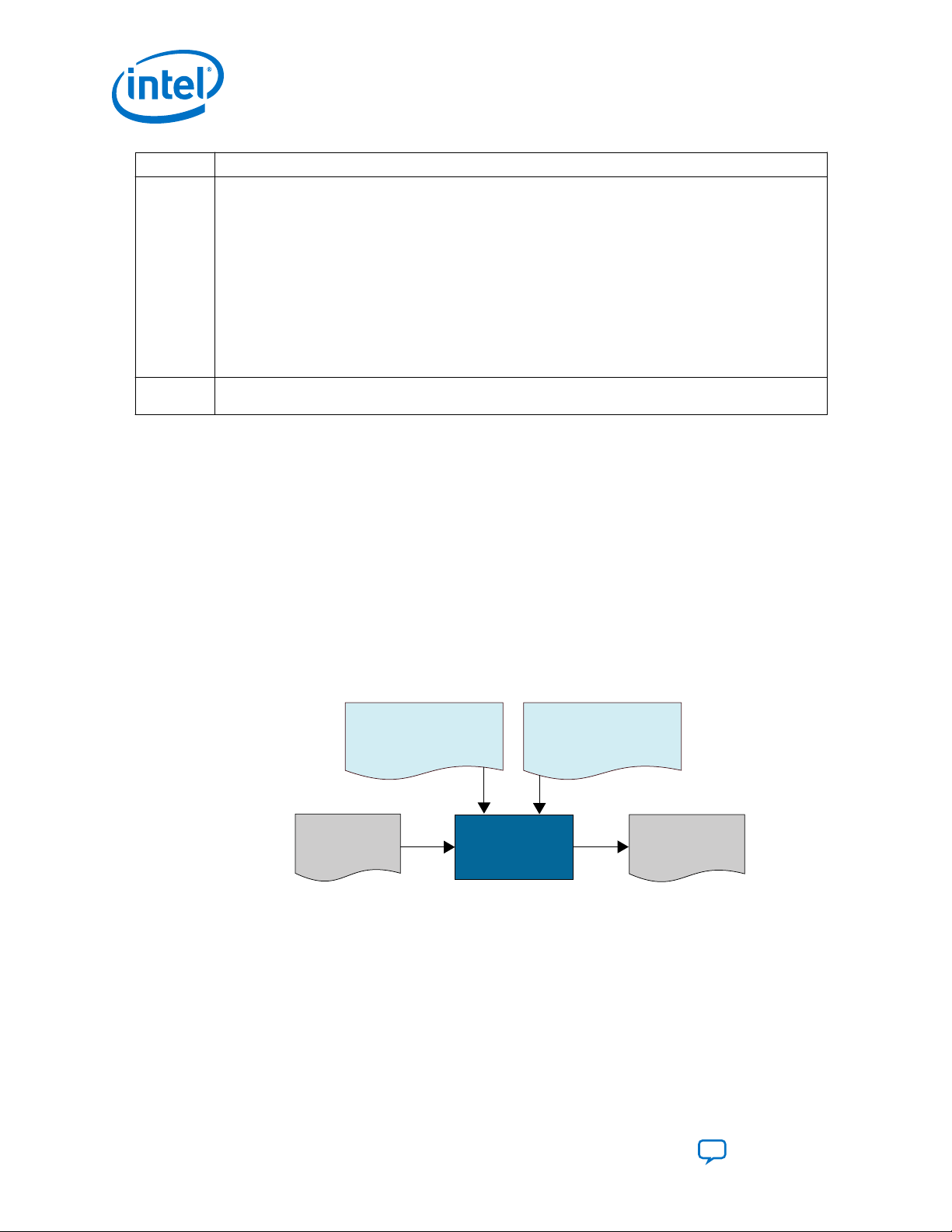
4.1. Using the Co-Signing Feature
The following figure provides an overview of the steps to create an signature chain to
co-sign the device firmware.
Firmware Co-Signing Design Flow
It shows the steps for the following operations:
1. Generating an owner firmware key as a second-level firmware signing key. You
append this second-level key (Owner FW Public .pem) to the existing key file to
create a new keychain (Owner FW Key .qky).
2.
Co-signing the firmware. Add the owner signature to nadder.zip using the new
keychain and the Owner FW Private .pem file.
Intel Corporation. All rights reserved. Agilex, Altera, Arria, Cyclone, Enpirion, Intel, the Intel logo, MAX, Nios,
Quartus and Stratix words and logos are trademarks of Intel Corporation or its subsidiaries in the U.S. and/or
other countries. Intel warrants performance of its FPGA and semiconductor products to current specifications in
accordance with Intel's standard warranty, but reserves the right to make changes to any products and services
at any time without notice. Intel assumes no responsibility or liability arising out of the application or use of any
information, product, or service described herein except as expressly agreed to in writing by Intel. Intel
customers are advised to obtain the latest version of device specifications before relying on any published
information and before placing orders for products or services.
*Other names and brands may be claimed as the property of others.
ISO
9001:2015
Registered
Page 24

4. Co-Signing Device Firmware Overview
UG-S10SECURITY | 2019.05.10
Note:
The Intel Quartus Prime Software automatically generates nadder.zip.
This file includes the firmware for the SDM in Intel Stratix 10 device. The
Intel Quartus Prime Software writes this file to the <install_dri>/
quartus/common/devinfo/programmer/firmware/ directory.
3. Programming the Co-Signed Firmware eFuses in the the Intel Stratix 10 device
using the signed firmware (Signed FW signed_nadder.zip) and owner.fuse
as inputs.
Note: You must power cycle your board after programming the fuses.
4.1.1. Prerequisites for Co-Signing Device Firmware
Before completing the steps to co-sign device firmware, you must generate an owner
root key and program the owner public key hash eFuse.
To generate the owner root key follow the instructions in Using the Authentication
Feature Step 1: Creating the Root Key or by using your own custom hardware security
module.
Then program the owner public key hash into eFuses using the following command:
quartus_pgm -c 1 -m jtag -o "p;root_public.qky"
Alternatively, you can use the Intel Quartus Prime Programmer to program the owner
root key as described in Step 5: Programming the Owner Public Root Key for
Authentication.
Related Information
• Step 5: Programming the Owner Public Root Key for Authentication on page 20
• Step 1: Creating the Root Key on page 15
4.1.2. Generating the Owner Firmware Signing Key
You use the Intel Quartus Prime Signing Tool operation=append_key to append a
second-level firmware signing key to the owner root public key. The permission is set
to 1 for firmware. The Intel Quartus Prime Signing Tool allows you to append up to
three keys, including the owner root key.
The first two steps generate required inputs to the operation=append_key
command shown in Step 3.
1. Run the following command to generate the firmware private key.
quartus_sign --family=stratix10 --operation=make_private_pem -curve=prime256v1 owner_fw_private.pem
2. Run the following command to generate the firmware public key from
owner_fw_private.pem.
quartus_sign --family=stratix10 --operation=make_public_pem
owner_fw_private.pem owner_fw_public.pem
Intel® Stratix® 10 Device Security User Guide
24
Send Feedback
Page 25

4. Co-Signing Device Firmware Overview
UG-S10SECURITY | 2019.05.10
3.
Run the following command to append the owner_fw_public.pem owner root
keychain
quartus_sign --family=stratix10 --operation=append_key \
--previous_pem=owner_root_private.pem --previous_qky=owner_root_public.qky
--permission=0x1 --cancel=1 owner_fw_public.pem owner_fw_key.qky
4.1.3. Co-Signing the Firmware
You use the Intel Quartus Prime Signing Tool operation=sign to sign the firmware
with your private firmware key. If you are using your own custom hardware security
module you can co-sign using your own script.
1. Run the following command to co-sign the firmware file. The firmware file is
nadder.zip. The Intel Quartus Prime Software writes this file to the
<install_dri>/ quartus/common/devinfo/programmer/firmware/
directory.
quartus_sign --family=stratix10 --operation=sign --qky=owner_fw_key.qky \
--pem=owner_fw_private.pem nadder.zip nadder_signed.zip
4.1.4. Programming the Co-Signed Firmware eFuses
You program the Co-Signed Firmware eFuses to enable co-signing.
Before you can program the Co-Signed Firmware eFuses, you must check the current
state of eFuse programming for your device. This procedure ensures that you add the
new eFuse commands to the existing eFuse programming commands, if any.
The example commands specify the helper_device 1SX280LH2. If you are using a
different Intel Stratix 10 device, provide the appropriate ordering code for that device
up to the speed grade designation. Helper images are necessary for flash and fuse
programming using the Intel Quartus Prime Programmer.
1. To find the list of helper devices, in the Intel Quartus Prime Programmer, select
Add Device.
2. In the Device family list, select Intel Stratix 10. In the Device name list,
identify the find the part number that matches your device.
Send Feedback
Intel® Stratix® 10 Device Security User Guide
25
Page 26

Possible Values
for
helper_device
Add Device
4. Co-Signing Device Firmware Overview
UG-S10SECURITY | 2019.05.10
Figure 10. User the Programmer to Determine the helper_device Argument
3. Generate a preliminary (helper) image for eFuse programming.
quartus_pfg --helper_image -o helper_device=1SG280HN2 -o subtype=FUSE \
-o fw_source=nadder.zip helper_image.rbf
4.
Configure your Intel Stratix 10 device with the helper_image.rbf file you just
created.
quartus_pgm -c 1 -m jtag -o “p;helper_image.rbf”
5.
Generate the current device fuse status file, programming_file.fuse.
quartus_pgm -c 1 -m jtag -o “e;programming_file.fuse;1SX280LH2”
6.
Edit programming_file.fuse to add the four Co-Signed Firmware eFuses.
There are four copies of the Co-Signed Firmware eFuse. Programming changes all
4 copies from 0 to 1. Add the following command to programming_file.fuse.
Co-signed firmware = "0xF"
7. Program the Co-Signed Firmware eFuses:
quartus_pgm -c 1 -m jtag -o "p;programming_file.fuse"
Related Information
Intel Stratix 10 GX/SX Device Overview
For an explanation of Intel Stratix 10 device ordering codes.
Intel® Stratix® 10 Device Security User Guide
26
Send Feedback
Page 27

4. Co-Signing Device Firmware Overview
UG-S10SECURITY | 2019.05.10
4.1.5. Powering On In JTAG Mode After Implementing Co-Signed Firmware
After you program the co-signed firmware eFuses, the Intel Stratix 10 FPGA requires
programming files to have co-signing enabled at the next power-on. Consequently, the
original helper_image.rbf is no longer valid. To program the device successfully
you must regenerate a new helper_image.rbf file.
To add security features, You can regenerate the helper_image.rbf with co-signed
nadder.zip, load the .rbf then, program the .fuse file.
4.1.6. Canceling Intel Firmware ID
You may need to cancel pre-production Intel firmware IDs that are programmed into
your Intel Stratix 10 device.
The Intel Stratix 10 Secure Device Manager (SDM) is the gatekeeper for FPGA
configuration. When you enable authentication or encryption the SDM ensures that
only bitstreams that are correctly signed or encrypted or both signed and encrypted to
configure the device.
The SDM includes embedded processors that perform the authentication and
decryption functions. These processors run firmware that is embedded in the
configuration bitstream. The processors ensure that the firmware is valid.
In pre-production release firmware development, early firmware used cancellation ID
values 0 to 3. The official release version of the firmware for Intel Quartus Prime
Release 19.1 has a cancellation ID value of 4. To prevent earlier developmental
firmware versions from running in the SDM, you must cancel ID values 0 to 3 in the
Intel Firmware Cancellation ID table.
Canceling earlier IDs ensures that only bitstreams that are signed with the latest
secure and trusted version of the SDM firmware load into the FPGA. These ID values
are canceled by programming eFuses in the FPGA. This cancellation is permanent. This
requirement only applies to Intel Stratix 10 devices that have the owner root key hash
programmed in a physical (non-volatile) eFuse. If you have not programmed the
owner root key eFuse, any version of the SDM firmware can run.
If you have already programmed the owner root key hash into eFuses, once you load
a design into the FPGA that you created with version 19.1 or later, the firmware
automatically cancels IDs 0 to 3. Once IDs 0 to 3 are canceled, you are only be able to
program bitstreams created with version 19.1 or later. If you have designs created
with an earlier version of the Intel Quartus Prime Programmer, use the Programmer to
generate a new bitstream from the earlier .sof file.
If you have bitstreams that are loaded into the FPGA from flash memory, it is
important to recreate them using the latest firmware and reflash memory before
canceling the IDs in the FPGA. If you do not recreate the bitstreams, the bitstreams
do not load into the FPGA after the IDs have been canceled.
Send Feedback
Intel® Stratix® 10 Device Security User Guide
27
Page 28

4.1.6.1. Canceling Non-Volatile eFuses
If you have already programmed the owner root key hash into eFuses, you must
manually cancel IDs 0, 2, and 3 in the FPGA. When you programmed the owner root
key hash into eFuses, ID 1 was automatically canceled.
Follow these steps to cancel eFuses that specify SDM firmware versions that are no
longer valid.
1. Extract the existing fuse information by running the following command-line
command:
quartus_pgm -c 1 -m jtag -o "ie;my_fuse.fuse;1SX280LH2"
This command generates a my_fuse.fuse text file.
Sample contents of my_fuse.fuse:
# Co-signed firmware = "0xF"
# Device not secure = "0x0"
# Intel key cancellation = ""
# Owner fuses =
"0x00000000000000000000000000000000000000000000000000000
000000000000000000000000000000000000000000000000000000
000000000000000000000000000000000000000000000000000000
000000000000000000000000000000000000000000000000000000
00000000000000000000000000000000000000000"
# Owner key cancellation = ""
# Owner public key hash =
"0x000000000000000000000000000000000CE520B15B082E67ACEBCB8545CE239FDBB8CDE60
83F6DF9D3BF542932EA5039"
# Owner public key size = "0xF"
# QSPI start up delay = "0x0"
# SDMIO0 is I2C = "0x0"
4. Co-Signing Device Firmware Overview
UG-S10SECURITY | 2019.05.10
2.
2. Using a text editor, update my_fuse.fuse to specify the keys to cancel.
Change:
#Intel key cancellation = ""
to:
Intel key cancellation = "0,2,3"
Note:
Be sure to remove the initial #.
3. Run the following command to program the cancellation ID eFuses in the FPGA:
quartus_pgm -c 1 -m jtag -o "p;my_fuse.fuse" --non_volatile_key
4. Program the cancellation IDs in the virtual eFuses:
quartus_pgm -c 1 -m jtag -o "p;my_fuse.fuse"
Intel® Stratix® 10 Device Security User Guide
28
Send Feedback
Page 29

4. Co-Signing Device Firmware Overview
UG-S10SECURITY | 2019.05.10
4.1.6.2. Understanding Cancellation IDs on Pre-Production Designs
The Intel Quartus Prime Programmer combines the .sof and SDM firmware file,
nadder.zip, to generate the configuration bitstream for Intel Stratix 10 devices. The
SDM firmware signed with an Intel authentication key and has a cancellation ID. The
bitstream also includes any authentication and encryption operations you specified.
The resulting bitstream can be a .pof or .rbf file.
If you generate the bitstream file with the Intel Quartus Prime Software version 19.1
or earlier, the cancellation ID value is 0 to 3. Once the Programmer cancels these IDs,
the bitstreams that include these firmware versions cannot configure the Intel Stratix
10 device. To run earlier versions of a design, you must recreate the bitstream file
with the newer version of the Programmer. It is not necessary to recompile the design
because the Programmer uses the existing .sof.
Send Feedback
Intel® Stratix® 10 Device Security User Guide
29
Page 30

UG-S10SECURITY | 2019.05.10
Send Feedback
5. Signing Command Detailed Description
The signing command, quartus_sign, supports the following functions:
• Generates the private and public PEM files
• Generates the signature chain starting with the public root key
• Appends additional public keys to the signature chain
• Signs the unsigned bitstream
•
Calculates the root key hash from the signature chain file .qky file
The quartus_sign command always specifies the FPGA device family and operation.
Here is the general format of the command:
quartus_sign --family=stratix10 --operation=<type of operation> [additional
arguments]
The following table summarizes all the quartus_sign operations.
Table 3. Signing Command Argument Summary
Argument Options Description
operation make_private_pem Generates a private key in .pem format such as
make_public_pem Generates a public key in .pem format from the private .pem
make_root Generates public root key in .key format such as
append_key
sign Signs the bitstream with the .pem private key and key chain.
fuse_info Calculates the public root key hash from the .key file.
root_private.pem.
such as root_public.pem.
root_public.qky.
Appends an additional public key to the signature chain and
generates a key chain in .keyformat, such as
design0_sign_chain.qky.
The following topics provide details on each operation. The operations are listed in the
order that you normally run them to create a signature chain, sign the bitstream, and
calculate the root key hash.
Intel Corporation. All rights reserved. Agilex, Altera, Arria, Cyclone, Enpirion, Intel, the Intel logo, MAX, Nios,
Quartus and Stratix words and logos are trademarks of Intel Corporation or its subsidiaries in the U.S. and/or
other countries. Intel warrants performance of its FPGA and semiconductor products to current specifications in
accordance with Intel's standard warranty, but reserves the right to make changes to any products and services
at any time without notice. Intel assumes no responsibility or liability arising out of the application or use of any
information, product, or service described herein except as expressly agreed to in writing by Intel. Intel
customers are advised to obtain the latest version of device specifications before relying on any published
information and before placing orders for products or services.
*Other names and brands may be claimed as the property of others.
ISO
9001:2015
Registered
Page 31

5. Signing Command Detailed Description
UG-S10SECURITY | 2019.05.10
5.1. Generate Private PEM Key
The first step in generating the signature chain is creating the private PEM.
Command
Input file None
Output file Private PEM file
Arguments This command includes 1 required argument and 1 optional argument:
quartus_sign --family=stratix10 --operation=make_private_pem
--curve=<prime256v1 or secp384r1> <output private PEM file>
or:
quartus_sign --family=stratix10 --operation=make_private_pem
--curve=<prime256v1 or secp384r1> --no_passphrase
<output private PEM file>
•
curve: Selects the Elliptic Curve Digital Signature Algorithm (EDCSA) 256 or 384. Intel
recommends using the secp384r1 key if possible because the prime256v1 key may be
vulnerable to attacks within the next 20 years.
•
no_passphrase: By default the make_private_pem command encrypts the private key. You
can add the optional --no_passphrase argument create a plain text key. Intel recommends
using a passphrase because it makes the key file useless to an attacker.
5.2. Generate Public PEM Key
The second step in generating the signature chain is generating the public PEM file
from the private PEM file.
Command
Input file
Output file
Arguments This command has no additional arguments.
quartus_sign --family=stratix10 --operation=make_public_pem
<input private PEM file> <output public PEM file>
input private PEM file: This is the file that the make_private_pem generates.
output public PEM file: make_public_pem generates this file.
5.3. Generate Root Signature Chain
The third step in generating the signature chain makes the root public key by
converting the public key PEM file to the Intel Quartus Prime key format.
Command
Input file
Output file
Arguments This command has no additional arguments.
quartus_sign --family=stratix10 --operation=make_root
<input root public PME file> <output root public qky file>
input public PEM file: This is the file that the make_public_pem generates.
output root public qky file: make_root generates this file.
5.4. Append Key to Signature Chain
The append command implements the following functions:
• —
Send Feedback
Converts the public PEM file to the root public key in .qky format.
— Signs the new root public key.
— Appends the specified design signing key to the public root key.
Intel® Stratix® 10 Device Security User Guide
31
Page 32

5. Signing Command Detailed Description
UG-S10SECURITY | 2019.05.10
Command
Input files
Output file
Arguments This command includes 2 arguments:
quartus_sign --family=stratix10 --operation=append_key
--previous_pem==<private PEM for the public key of last entry
in input QKY> --previous_qky=<input QKY>
--permission=<permission value to authenticate> --cancel=<cancel ID>
<public PEM for new entry> <output QKY>
The append_key command has 2 input files:
•
previous_pem: The private PEM file that is input to the make_public_pem operation. This
private PEM is from the previous entry in the input signature chain.
•
previous_qky: The previous key in the signature chain.
The append_key outputs 2 files:
•
public_pem: This is the new key in PEM format.
•
output_key: This is the new signature chain with one additiona l entry.
•
permission: Sets the signing key permission value. Each bit grants permission to sign a
particular type of data. The following values are valid:
— 0: to sign firmware
— 1: to sign FPGA I/O, core sections, and PR sections
— 2: to sign HPS I/O and the FSBL
•
cancel: Specifies the number of the eFuse to program to cancel this signature. The valid
range is 32-63.
5.5. Sign the Bitstream
The sign operation takes an unsigned image.rbf or firmware.zip as input. The
sign operation generates a signed output file, either signed_image.rbf or signed_
firmware.zip.
For .rbf generation, you convert the .sof to an .rbf using either the Intel Quartus
Prime File ➤ Programming File Generator dialog box or the quartus_pfg
command-line command.
Command
Input file The sign operation supports the following 2 input file types:
Output file
Arguments This command has 2 additional arguments:
quartus_sign --family=stratix10 --operation=sign --qky=<qky file>
--pem=<private PEM for the public key of last entry in the input QKY>
<unsigned rbf or unsigned nadder file> <signed rbf or nadder file>
•
unsigned rbf file: This is the .rbf that you generate from the .sof
•
unsigned nadder file: quartus/common/devinfo/programmer/firmware/
nadder.zip. This file contains the SDM firmware.
signed rbf file or signed nadder file: This file is the output of the sign operation.
•
qky: This is the .qky file generated by the previous append_key or make_root operation.
•
pem: This is the private PEM for the previous public key of the input QKY.
Refer to Step 4: Signing the Bitstream for the steps to sign the bitstream using the
Programing File Generator tool.
Related Information
Step 4: Signing the Bitstream on page 17
Intel® Stratix® 10 Device Security User Guide
32
Send Feedback
Page 33

5. Signing Command Detailed Description
UG-S10SECURITY | 2019.05.10
5.6. Calculate Public Root Key Hash from QKY
The fuse_info operation calculates the hash of the root public key.
Command
Input file
Output file
Arguments This command has no additional arguments.
quartus_sign --family=stratix10 --operation=fuse_info <input QKY>
<fuse output text>
input QKY: This is the public root key.
fuse output text: Manufacturing uses this text file to program the specified eFuses of the Intel
Stratix 10 device. This process is irreversible. You can simulate this process using virtual eFuses.
eFuses reset when you power-cycle the pcb.
Send Feedback
Intel® Stratix® 10 Device Security User Guide
33
Page 34

N+1 127-bit Block
KeySub-root Key Data DataData
N+1 127-bit Block
KeyData DataData
UG-S10SECURITY | 2019.05.10
Send Feedback
6. Encryption and Decryption Overview
A single AES root key under owner control encrypts the dynamic blocks of Intel Stratix
10 bitstream. The firmware block is static for particular release of the Intel Quartus
Prime software.
Encryption Process
You can store the owner AES Root key in eFuses, BBRAM, or a PUF-wrapped key. The
AES root key encrypts an intermediate key chain derived from AES root key. Each key
in the key chain encrypts the next key in the chain. The last key in key chain encrypts
a key block which contains a derived key for each sector.
To prevent overuse of the AES root key, the AES root key does not encrypt the keys
directly. Instead, the root key encrypts a chain of intermediate keys. The root key
encrypts the first intermediate key, which encrypts the second intermediate key, and
so on. The last intermediate key encrypts the section keys.
Encryption supports up to 20 intermediate keys. By default, the encryption function
uses three intermediate keys. These keys mitigate side channel attack risk by
reducing the amount of data encrypted by any key.
In addition to intermediate keys, the AES update mode limits the amount of data
encrypted with the same key. Key update mode inserts a new key encrypted with the
old key every (N * 127 bits). The current release sets <N> to 127. When <N> is
127, the encrypted payload size increases by 0.8%. This mode prevents an attacker
from getting enough encrypted data to derive they encryption key,
Figure 11. AES Update Mode
Decryption Process
The section key decrypts the keys block which contains up to 128 keys. Each key is
256 bits and decrypts subsequent encrypted data or another keys block.
Intel Corporation. All rights reserved. Agilex, Altera, Arria, Cyclone, Enpirion, Intel, the Intel logo, MAX, Nios,
Quartus and Stratix words and logos are trademarks of Intel Corporation or its subsidiaries in the U.S. and/or
other countries. Intel warrants performance of its FPGA and semiconductor products to current specifications in
accordance with Intel's standard warranty, but reserves the right to make changes to any products and services
at any time without notice. Intel assumes no responsibility or liability arising out of the application or use of any
information, product, or service described herein except as expressly agreed to in writing by Intel. Intel
customers are advised to obtain the latest version of device specifications before relying on any published
information and before placing orders for products or services.
*Other names and brands may be claimed as the property of others.
ISO
9001:2015
Registered
Page 35

Header Block
Intel Stratix 10
IVs & Intermediate Keys
Owner AES Root Key
Section Key of Header
Block decrypts
Keys Block 0
Keys in Keys
Block 0 decrypt the
adjacent blocks
including Keys Block N
Total of 128 items decrypted
by keys stored in Keys
Block 0
Owner AES Root Key decrypts first
Intermediate Key that decrypts
next Intermediate Key. The last
Intermediate Key decrypts
the Section Key.
Signature Block
Initialization Vector (IV) for Keys Block 0
IVs for Subsequence Encrypted Data
Encrypted Data 1
IV & Section Key
Keys Block 0 (up to 128 keys)
IV for Keys Block N
Keys Block N(Up to 128 keys)
Encrypted Data 2
Encrypted Data 126
6. Encryption and Decryption Overview
UG-S10SECURITY | 2019.05.10
Figure 12. Bitstream Decryption
The initialization vector (IV) is unencrypted data that is an input to the decryption
function.
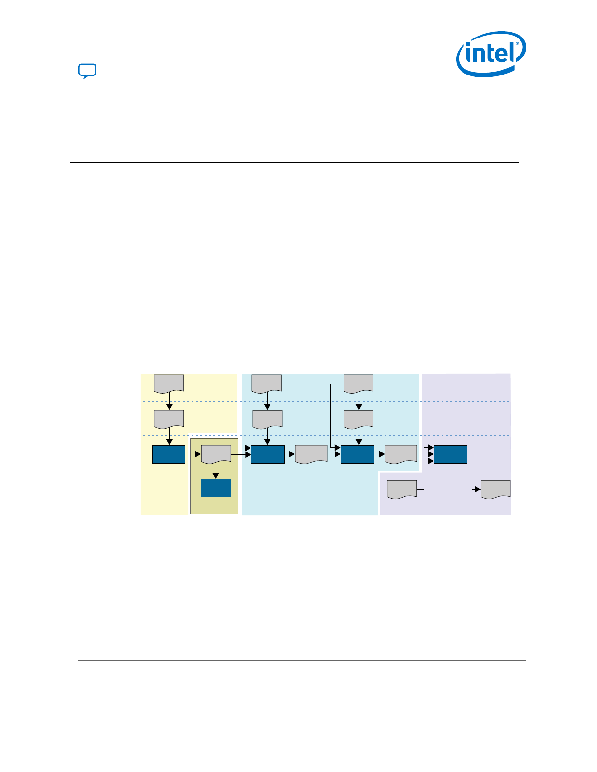
6.1. Using the Encryption Feature
Encrypting the owner image includes the following three steps:
• Step 1: Preparing the owner image and AES key files
• Step 2: Generating the programming files
• Step 3: Programming the AES key and configuring the encrypted owner image
The following flow diagram shows the processes required for each step.
Send Feedback
Intel® Stratix® 10 Device Security User Guide
35
Page 36

Stage #1
Prepare SOF and QEK
Stage #2
Programming File Generation
Passwordword
protected.qek
.sof with Encryption
Enable and
Key Select Option
PFG Encryption Option:
Use Factory Script
(stratix10_encrypt.py)
or Custom Script
Encrypted
.rbf/.jic/.pof/.rpd
Programmer
Stage #3
Program owner AES root key
(.qek) to the device (physical
eFUSE/Virtual eFUSE/
BBRAM), and then configure
device with encrypted
bitstream
Device
quartus_encrypt
(stratix10_encrypt.py)
6. Encryption and Decryption Overview
UG-S10SECURITY | 2019.05.10
Figure 13. Design Flow for Owner Image Encryption in Intel Stratix 10 Devices
6.1.1. Step 1: Preparing the Owner Image and AES Key File
Before you generate the owner image and AES key file, you must specify
authentication settings on the Authentication and Encryption page of the Device
and Pin Options.
1.
On the Authentication and Encryption page (Assignments ➤ Device ➤
Device and Pin Options ➤ Authentication and Encryption), for Quartus Key
File specify your root key file or signature key chain.
Note: Providing a root key enables other security features such as encryption in
Intel Stratix 10 devices.
2. Turn on the Enable Programming Bitstream Encryption option.
3. Specify the key storage location from Encryption Key Select drop-down list.
Intel recommends that you choose Virtual eFuses during development.
4.
Generate the AES key using the quartus_encrypt command:
quartus_encrypt --family=stratix10 --operation=make_aes_key <output.qek>
Note:
If you prefer, you can use your own custom script to generate the .qek file.
6.1.2. Step 2a: Generating Programming Files Using the Programming File Generator
You can use the Programming File Generator to encrypt and sign the owner image.
The Programming File Generator supports the following signed and encrypted output
file types:
•
Raw Binary File (.rbf)
•
JTAG Indirect Configuration File (.jic)
•
Programmer Object File (.pof)
•
Raw Programming Data File (.rpd)
Intel® Stratix® 10 Device Security User Guide
36
Send Feedback
Page 37

Output file type
Configuration scheme
Output file tab
Specify encryption key
Enable authentication
Enable encryption
Specify private root .pem
6. Encryption and Decryption Overview
UG-S10SECURITY | 2019.05.10
1. On the Intel Quartus Prime File menu select Programming File Generator.
2. On the Output Files tab, specify the output file type for your configuration
scheme.
Figure 14. Output File Specification
3.
On the Input Files tab, click Add Bitstream and browse to your .sof.
4.
To specify encryption and authentication options select the .sof and click
Properties.
a. Turn Enable signing tool on.
b.
For Private key file select your root private .pem file.
c. Turn Finalize encryption on.
d.
For Encryption key file, select your AES .qek file.
Figure 15. Input (.sof) File Properties for Authentication and Encryption
5. To generate the signed and encrypted bitstream, on the Input Files tab, click
Send Feedback
Generate, top.rbf.
Intel® Stratix® 10 Device Security User Guide
37
Page 38

Specify Quartus
Prime Key File
Select Key
Storage Location
6. Encryption and Decryption Overview
UG-S10SECURITY | 2019.05.10
6.1.3. Step 2b: Generating Programming Files Using the Command Line Interface
For JTAG or Avalon-ST configuration schemes, you can use the quartus_pfg script to
generate the signed and encrypted output file.
Generating the fully encrypted programming files is a two-step process.
1. In your output files directory, run the following command:
quartus_pfg -c encryption_enabled.sof test.rbf partly_encrypted.rbf \
-o finalize_encryption_later=ON -o sign_later=ON
2.
Run the quartus_encrypt command or your own custom script to finalize the
partially encrypted .rbf file.
quartus_encrypt --family=stratix10 --operation=encrypt --key=aes.qek
partly_encrypted.rbf encrypted.rbf
6.1.4. Step 3a: Specifying Keys and Configuring the Encrypted Image Using the Intel Quartus Prime Programmer
You should already have specified a storage location for your .qek on the
Authentication and Encryption page of the Assignments ➤ Device ➤ Device and
Pin Options. In the current release, you can select Battery Backup RAM (BBRAM)
or Virtual eFuses. When you generate the .sof the Intel Quartus Prime Software
records the key you specify to partially encrypt the configuration bitstream.
Figure 16. Specify Storage Location for Encryption Key
1. Bring up the Intel Quartus Prime Programmer.
2. Right click the Intel Stratix 10 device and select Add QKY/QEK/FUSE File file.
Navigate to your .qky file and select it.
Intel® Stratix® 10 Device Security User Guide
38
Send Feedback
Page 39

Program/
Configure
6. Encryption and Decryption Overview
UG-S10SECURITY | 2019.05.10
Figure 17. Adding .qky, .qek or .fuse files
3.
Enable the Program/Configure option for the .qky file. Disable the Program/
Configure for any other files that may be selected. Click Start to program the
authentication key into your Intel Stratix 10 device.
Figure 18. Program/Configure A Key File
Note:
4. Right click the Intel Stratix 10 device and select Add QKY/QEK/FUSE File.
Navigate to your .qek file and select it.
5.
Enable the Program/Configure option for the .qek file. Disable the Program/
Configure for any other files that may be selected. Click Start. The Passphrase
dialog box appears. Enter your passphrase. The encryption key programs into the
BBRAM or virtual eFuses on the Intel Stratix 10 device.
6.
With the keys programmed, you can load the signed and encrypted .rbf
bitstream image.
Option
Using the Intel Quartus Prime Programmer: Enable the Program/Configure option for
Using a Intel MAX® 10 device or other external
host:
Description
the .rbf file. Disable the Program/Configure
for any other files that may be selected. Click
Start.
Instruct the configuration hardware to configure
the Intel Stratix 10 device from the flash memory.
If you programmed the authentication key into physical eFuses, it is important to
remove this directive until you intend to do additional physical eFuse programming.
Select Tools ➤ Options ➤ Programmer to restore the Enable device security
using a volatile security key setting. Having volatile security selected ensures that
you do not program physical eFuses unintentionally.
Physical eFuses are not supported in the current release.
Send Feedback
Intel® Stratix® 10 Device Security User Guide
39
Page 40

6. Encryption and Decryption Overview
UG-S10SECURITY | 2019.05.10
6.1.5. Step 3b: Programming the AES Key and Configuring the Encrypted Image Using the Command Line
You use the Intel Quartus Prime Programmer to program the owner AES key into the
device. Then, configure the device using the encrypted bitstream.
You should already have specified a storage location for your .qek as explained in
Step 3a: Using the Intel Quartus Prime Programmer to Specify Keys and Configure the
Device.
1.
You can program the key file using the quartus_pgm command:
quartus_pgm -c 1 -m jtag -o "pi;aes.qek"
The command arguments specify the following information:
•
-c: cable number
•
-m: mode
•
-o: operation. The argument to operation is enclosed in quotes. The letters
specify the following operations:
—
p: program
—
i: load a helper image which loads the SDM firmware so that it can
program the aes.qek
—
;: the argument following the ; specifies the programming file
2. Now program the signed encrypted bitstream using the following commands:
quartus_pgm -c 1 -m jtag -o "p;encrypted.rbf"
Intel® Stratix® 10 Device Security User Guide
40
Send Feedback
Page 41

Row 0
Bank 0
32-bit word
32-bit word
32-bit word
Row 63
Row 0
Bank 1
32-bit word
32-bit word
32-bit word
Row 63
Row 0
Bank 2
32-bit word
32-bit word
32-bit word
Row 63
Row 0
Bank 3
32-bit word
32-bit word
32-bit word
Row 63
UG-S10SECURITY | 2019.05.10
Send Feedback
7. Using eFuses
eFuses store the security and other Intel Stratix 10 device information. Intel Stratix 10
devices have a total of 8192 eFuse bits organized in four equal banks. Each bank has
64 rows. Each row has 32 eFuse bits.
Figure 19. eFuse Mapping
Table 4. Owner Programmable eFuses
Bank Description Size (Bits) Legal Values Comments
0 Intel FPGA public key hash 384 96-bit hex Read only. 32 fuses are available.
0 Intel FPGA public key cancellation 128 boolean Read only. There are 4 redundant
cancellation bits associated with
each fuse. All 4 are programmed
when you cancel the corresponding
fuse.
Intel Corporation. All rights reserved. Agilex, Altera, Arria, Cyclone, Enpirion, Intel, the Intel logo, MAX, Nios,
Quartus and Stratix words and logos are trademarks of Intel Corporation or its subsidiaries in the U.S. and/or
other countries. Intel warrants performance of its FPGA and semiconductor products to current specifications in
accordance with Intel's standard warranty, but reserves the right to make changes to any products and services
at any time without notice. Intel assumes no responsibility or liability arising out of the application or use of any
information, product, or service described herein except as expressly agreed to in writing by Intel. Intel
customers are advised to obtain the latest version of device specifications before relying on any published
information and before placing orders for products or services.
*Other names and brands may be claimed as the property of others.
continued...
ISO
9001:2015
Registered
Page 42

7. Using eFuses
UG-S10SECURITY | 2019.05.10
Bank Description Size (Bits) Legal Values Comments
0 Co-signed firmware 4 4-bit boolean When you program this fuse, both
0 Device not secure 4 4-bit boolean The device becomes secure when
0 Intel key cancellation 128 boolean 1-32
0 Owner encryption key program
done
0 Owner encryption key program start 4 4-bit boolean
0 Owner key cancellation 128 [1,2] 0-31. There are 4 redundant
0 Owner public key hash 384 96-bit hex —
0 Owner public key size 8 [0, 256, 384]
3 Owner-defined fuses
4 4-bit boolean These fuses prevent overcurrent of
you and Intel must sign the device
firmware. Intel signs the device
firmware with the root public key
during the manufacturing process.
you program the owner root key in
either volatile or non-volatile
eFuses.
the AES root key stored in fuses.
The start fuses are programmed
before any row of the AES key has
been programmed. The end fuses
are programmed when the
complete key has been
programmed. An AES key
programming failure leaves the key
in an unusable state but does not
reveal information about the partial
AES key.
cancellation bits associated with
each fuse. All 4 are programmed
when you cancel the corresponding
fuse.
—
Simulating eFuses
You can use eFuses for authentication and also to enforce other security policies. For
example, you can store the AES key in eFuses, a BBRAM or a PUF-wrapped key. If
your design stores the AES key in eFuses, you can disable the BBRAM root key fuse
for additional security.
Because eFuses are non-volatile, Intel recommends validating eFuse programming
before programming actual eFuses on the Intel Stratix 10 device.
Intel® Stratix® 10 Device Security User Guide
42
Send Feedback
Page 43

7. Using eFuses
UG-S10SECURITY | 2019.05.10
Complete the following steps to validate eFuses:
1. Turn on Enable device security using a volatile security key in the Intel
Quartus Prime Programmer. When you select this option the Intel Quartus Prime
Pro Edition stores the eFuse values in firmware registers.
2. In the Intel Quartus Prime Programmer click Add File and browse to your signed
bitstream.
3. In the Intel Quartus Prime Programmer turn on the Program/Configure and
Examine options.
4. Click Start.
5. After programming completes, the Programmer displays the hash value of the
signature key stored in firmware. You can now compare that value to the value
you generate by creating a hash_fuse.txt file using the quartus_sign
command with the operation set to fuse_info.
Related Information
Step 5b: Calculating the Owner Public Root Key Hash on page 22
7.1. Fuse Programming Input Files
The Intel Quartus Prime Programmer supports the following three input file types for
fuse programming. Intel Quartus Prime key file (.qky), the Intel Quartus Prime
encryption key (.qek), and the .fuse file.
The files provide the following information to the Intel Quartus Prime Programmer:
•
.qky: Provides the owner public root key for authentication and the second-level
key for firmware authentication. Use this file for the following functions:
— To program and verify the public root key fuses
— To sign the owner configuration bitstream
— To sign the device firmware
•
.qek: Provides the AES key for encryption. Use this file for the following
functions:
— To program and verify the AES key fuses
— To encrypt the owner configuration bitstream
•
.fuse: Specifies all owner fuses. Also includes the public root key and the AES
key which are read-only. Use this file for the following functions:
— To program and verify security fuses
— To program owner-defined fuses
Send Feedback
Intel® Stratix® 10 Device Security User Guide
43
Page 44

7. Using eFuses
UG-S10SECURITY | 2019.05.10
7.1.1. Fuse File Format
The .fuse file contains a list of fuse name-value pairs. The value specifies whether
the fuse has been programmed (blown) and its cancellation ID.
The following example shows the format of the .fuse file.
# Comment
<fuse name> = <value>
<fuse name> = <value>
<fuse name> = <value>
You can use the Intel Quartus Prime Programmer Examine option to read all currently
programmed fuses in the Intel Stratix 10 device and store this information in a .fuse
file.
7.1.1.1. Converting Key, Encryption, and Fuse Files to Jam Staple File Formats
You can use the quartus_pfg command-line command to convert .qky, .qek,
and .fuse files to Jam * Standard Test and Programming Language (STAPL) Format
File (.jam) and Jam Byte Code File (.jbc). You can use these files to program Intel
FPGAs using the Jam STAPL Player and the Jam STAPL Byte-Code Player, respectively.
A single .jam or .jbc contains several functions including a firmware helper image
and program, blank check, and verification of key and fuse programming.
quartus_pfg Conversion Commands
Here are the quartus_pfg conversion commands:
quartus_pfg -c -o helper_device=1SX280LH2 root.qky nd_qky.jam
quartus_pfg -c -o helper_device=1SX280LH2 root.qky nd_qky.jbc
quartus_pfg -c -o helper_device=1SX280LH2 nd.qek nd_qek.jam
quartus_pfg -c -o helper_device=1SX280LH2 nd.qek nd_qek.jbc
quartus_pfg -c -o helper_device=1SX280LH2 cancel_id.fuse nd_fuse.jam
quartus_pfg -c -o helper_device=1SX280LH2 cancel_id.fuse nd_fuse.jbc
For more information about the using the Jam STAPL Player for device programming
refer to AN 425: Using the Command-Line Jam STAPL Solution for Device
Programming.
Related Information
AN 425: Using the Command-Line Jam STAPL Solution for Device Programming
Intel® Stratix® 10 Device Security User Guide
44
Send Feedback
Page 45

UG-S10SECURITY | 2019.05.10
Send Feedback
8. Document Revision History for Intel Stratix 10 Device Security User Guide
Document Version Intel Quartus
2019.05.10 19.1 Made the following corrections:
Prime Version
• Removed spaces before the fuse programming file name in the
quartus_pgm commands in Step 3b: Programming the AES Key and
Configuring the Encrypted Image Using the Command Line.
•
Changed file name argument to -o "p;my_fuse.fuse" in Step 4 of
Canceling Non-Volatile eFuses.
2019.05.07 19.1 Initial release.
Changes
Intel Corporation. All rights reserved. Agilex, Altera, Arria, Cyclone, Enpirion, Intel, the Intel logo, MAX, Nios,
Quartus and Stratix words and logos are trademarks of Intel Corporation or its subsidiaries in the U.S. and/or
other countries. Intel warrants performance of its FPGA and semiconductor products to current specifications in
accordance with Intel's standard warranty, but reserves the right to make changes to any products and services
at any time without notice. Intel assumes no responsibility or liability arising out of the application or use of any
information, product, or service described herein except as expressly agreed to in writing by Intel. Intel
customers are advised to obtain the latest version of device specifications before relying on any published
information and before placing orders for products or services.
*Other names and brands may be claimed as the property of others.
ISO
9001:2015
Registered
 Loading...