

Page 1

Intel® Server Board S875WP1-E
Product Guide
A Guide for Technically Qualified Assemblers of Intel® Identified Subassemblies/Products
Order Number: C32693-002
Page 2

Important Safety Instructions
Read all caution and safety statements in this document before performing any of the instructions.
See also Intel Server Boards and Server Chassis Safety Information on the Resource CD and/or at
http:\\support.intel.com
.
Disclaimer
Intel Corporation (Intel) makes no warranty of any kind with regard to this material, including, but not limited to, the implied
warranties of merchantability and fitness for a particular purpose. Intel assumes no responsibility for any errors that may
appear in this document. Intel makes no commitment to update nor to keep current the information contained in this
document. No part of this document may be copied or reproduced in any form or by any means without prior written consent
of Intel. Intel may make changes to documentation and product descriptions at any time, without notice.
®
An Intel
installation, it accurately stores, displays, processes, provides, and/or receives date data from, into, and between the
twentieth and twenty-first centuries, including leap year calculations, provided that all other technology used in combination
with said product properly exchanges date data with it.
Intel, and Pentium are the trademarks or registered trademarks of Intel Corporation or its subsidiaries in the United States
and other countries.
*
product, when used in accordance with its associated documentation, is "Year 2000 Capable" when, upon
Other names and brands may be claimed as the property of others.
ii
Copyright ©
2003 Intel Corporation.
Page 3

Contents
1 Server Board Features................................................................................... 9
Server Board Connector and Component Locations ............................................................11
Back Panel Connectors................................................................................................12
Front Panel Connectors ...............................................................................................12
Processor..............................................................................................................................13
Memory.................................................................................................................................13
Intel 875P Chipset.................................................................................................................14
Intel 82875P Memory Controller Hub (MCH) ...............................................................14
Intel 82801EB I/O Controller Hub (ICH5-R) .................................................................15
Intel 82802AC Firmware Hub (FWH) ...........................................................................15
Video.....................................................................................................................................15
AGP Connector............................................................................................................16
ATA Rage XL Video Controller.....................................................................................16
Video Modes..................................................................................................16
Video Memory Interface ................................................................................17
Super I/O...............................................................................................................................17
Serial Port ....................................................................................................................18
Parallel Port..................................................................................................................18
Floppy Drive Controller ................................................................................................18
Keyboard and Mouse Connectors................................................................................18
USB .....................................................................................................................................19
High-Speed USB 2.0 Support ......................................................................................19
Legacy USB Support....................................................................................................19
PCI I/O Subsystem................................................................................................................20
32-bit, 33-MHz PCI Subsystem....................................................................................20
Device IDs (IDSEL) .......................................................................................21
Data Storage.........................................................................................................................21
Serial ATA (SATA) .......................................................................................................21
IDE Interfaces ..............................................................................................................22
SCSI Hard Drive Activity LED Connector......................................................22
Network Interface Controller (NIC)........................................................................................23
NIC Connector and Status LEDs...................................................................23
Power Management..............................................................................................................24
Software Support through ACPI...................................................................................24
Wake-up Devices and Events .......................................................................26
Hardware Support........................................................................................................27
Power Connector...........................................................................................28
Fan Connectors.............................................................................................28
Instantly Available PC Technology................................................................29
Hardware Management and Monitoring................................................................................30
Chassis Intrusion and Detection ..................................................................................30
Password Security ................................................................................................................31
Real-Time Clock, CMOS SRAM, and Battery.......................................................................32
Recovering the CMOS..........................................................................................................32
iii
Page 4

BIOS .....................................................................................................................................33
PCI Auto Configuration.................................................................................................33
IDE Auto Configuration.................................................................................................33
BIOS Updates ..............................................................................................................34
Language Support.........................................................................................34
Custom Splash Screen..................................................................................35
Recovering BIOS Data.................................................................................................35
Boot Options ................................................................................................................35
CD-ROM and Network Boot ..........................................................................35
Booting Without Attached Devices................................................................36
Fast Booting Systems with Intel® Rapid BIOS Boot....................................................36
Intel Rapid BIOS Boot ...................................................................................36
System Management BIOS (SMBIOS) ........................................................................37
2 Server Board Installation and Upgrades.................................................... 39
Tools and Supplies Needed..................................................................................................39
Before You Begin..................................................................................................................39
Emissions Disclaimer...................................................................................................39
Warnings and Cautions.........................................................................................................39
Installing the I/O Shield.........................................................................................................41
Installing Chassis Standoffs..................................................................................................42
Intel Server Chassis SC5200 ........................................................................42
Intel® Server Chassis SC5250-E ...................................................................43
Installing the Server Board....................................................................................................44
Placing the Server Board into the Chassis....................................................44
Attaching the Server Board ...........................................................................44
Installing the Processor.........................................................................................................45
Removing the Processor.......................................................................................................48
Installing and Removing Memory..........................................................................................49
DIMM Installation Guidelines........................................................................................49
Installing DIMMs...........................................................................................................50
Removing DIMMs.........................................................................................................51
Installing and Removing an AGP Card .................................................................................51
Installing an AGP Card.................................................................................................52
Removing the AGP Card..............................................................................................52
Connecting the IDE Cable.....................................................................................................53
Connecting the Serial ATA Cable (Optional).........................................................................54
Connecting Internal Headers ................................................................................................55
Connecting the Front Panel Header.............................................................................55
Connecting the USB 2.0 Header..................................................................................56
Connecting Hardware Control and Power Cables ................................................................57
Connecting Fans..........................................................................................................58
Chassis Intrusion..........................................................................................................58
Connecting Power Cables............................................................................................58
Setting the BIOS Configuration Jumper................................................................................58
Clearing Passwords..............................................................................................................59
Replacing the Battery............................................................................................................60
iv Intel Server Board S875WP1-E Product Guide
Page 5

3 Configuration Software and Utilities......................................................... 63
Updating the BIOS with the Intel® Flash Memory Update Utility..........................................63
Obtaining the BIOS Update File...................................................................................63
Recording the Current BIOS Settings ..........................................................................64
Creating Bootable Media...............................................................................64
Creating a BIOS Update Media....................................................................................65
Updating the BIOS .......................................................................................................66
Recovering the BIOS ............................................................................................................67
Using the Setup Program......................................................................................................68
BIOS Setup Program Modes........................................................................................68
Maintenance Menu.......................................................................................................69
Main Menu....................................................................................................................70
Advanced Menu ...........................................................................................................71
PCI Configuration Submenu..........................................................................72
Boot Configuration Submenu ........................................................................73
Peripheral Configuration Submenu ...............................................................74
Drive Configuration Submenu .......................................................................76
Floppy Configuration Submenu.....................................................................79
Event Log Configuration Submenu................................................................80
Video Configuration Submenu.......................................................................81
USB Configuration Submenu ........................................................................82
Chipset Configuration Submenu....................................................................83
Fan Control Configuration Submenu.............................................................85
Hardware Monitoring Submenu.....................................................................86
Remote Access Configuration Submenu.......................................................87
Security Menu ..............................................................................................................88
Power Menu.................................................................................................................89
ACPI Submenu..............................................................................................89
Boot Menu....................................................................................................................90
Boot Device Priority Submenu.......................................................................91
Hard Disk Drives Submenu...........................................................................91
Removable Devices Submenu......................................................................92
ATAPI CDROM Drives Submenu..................................................................92
Exit Menu .....................................................................................................................93
4 Solving BIOS Problems............................................................................... 95
BIOS Beep Codes.................................................................................................................95
BIOS Error Messages...........................................................................................................96
5 Getting Help.................................................................................................. 99
World Wide Web...................................................................................................................99
Telephone.............................................................................................................................99
6 Technical Reference .................................................................................. 101
Server Board Connectors....................................................................................................101
Baseboard Connectors ..............................................................................................102
Power, Fan, Chassis Intrusion Connectors.................................................102
Add-In Board and Peripheral Interface Connectors.....................................103
Contents v
Page 6

Server Board Resources.....................................................................................................104
Memory Map ..............................................................................................................104
DMA Channels...........................................................................................................104
I/O Map .....................................................................................................................105
Interrupts....................................................................................................................106
7 Regulatory and Integration Information................................................... 107
Product Regulatory Compliance .........................................................................................107
Product Safety Compliance........................................................................................107
Product EMC Compliance..........................................................................................107
Product Regulatory Compliance Markings.................................................................108
Electromagnetic Compatibility Notices................................................................................109
FCC (USA).................................................................................................................109
INDUSTRY CANADA (ICES-003)..............................................................................110
Europe (CE Declaration of Conformity)......................................................................110
Taiwan Declaration of Conformity..............................................................................110
Korean RRL Compliance............................................................................................110
Australia / New Zealand.............................................................................................110
Installation Precautions.......................................................................................................111
Installation Requirements....................................................................................................111
Prevent Power Supply Overload................................................................................111
Place Battery Marking................................................................................................112
Use Only for Intended Applications............................................................................112
vi Intel Server Board S875WP1-E Product Guide
Page 7

Figures
Figure 1. Server Board Components..........................................................................................11
Figure 2. Back Panel Connectors...............................................................................................12
Figure 3. Front Panel Connectors...............................................................................................12
Figure 4. Location of the Standby Power Indicator LED CR7J1.................................................29
Figure 5. Location of Clear CMOS Jumper.................................................................................32
Figure 6. Installing the I/O Shield................................................................................................41
Figure 7. Installing Chassis Standoffs in the SC5200 Chassis...................................................42
Figure 8. Installing Chassis Standoffs in the SC5250-E Chassis ...............................................43
Figure 9. Placing the Server Board into the Chassis..................................................................44
Figure 10. Attaching the Server Board........................................................................................45
Figure 11. Installing the Processor in the Processor Socket ......................................................45
Figure 12. Attaching the Heat Sink to the Processor..................................................................46
Figure 13. Attaching the Fan Heat Sink Clips to the Processor Socket......................................47
Figure 14. Attaching the Fan Heat Sink Clips to the Processor Socket......................................47
Figure 15. Connecting the Processor Fan Cable to the Processor Fan Connector....................48
Figure 16. DIMM Socket Locations.............................................................................................50
Figure 17. Installing the AGP Card.............................................................................................52
Figure 18. Connecting the IDE Cable.........................................................................................53
Figure 19. Connecting the SATA Cable......................................................................................54
Figure 20. Location of Internal Headers......................................................................................55
Figure 21. Location of the Fan Headers and Power Connectors................................................57
Figure 22. BIOS Configuration Jumper Block Location ..............................................................58
Figure 23. Removing the Battery................................................................................................62
Figure 24. Power, Fan, and Chassis Intrusion Connectors.......................................................102
Figure 25. Add-in Board and Peripheral Interface Connectors.................................................103
Tables
Table 1. Server Board Features....................................................................................9
Table 2. Supported Processors...................................................................................13
Table 3. Video Modes..................................................................................................16
Table 4. PCI Bus Characteristics.................................................................................20
Table 5. PCI Bus Configuration IDs.............................................................................21
Table 6. 10/100 Ethernet LAN Connector LEDs..........................................................23
Table 7. 10/100/1000 Gigabit Ethernet LAN Connector LEDs....................................24
Table 8. Effects of Pressing the Power Switch under ACPI........................................25
Table 9. Wake-up Devices and Events .......................................................................26
Table 10. Fan Connector Function/Operation...............................................................28
Table 11. Supervisor and User Password Functions ....................................................31
Table 12. Front Panel Header (J7J1)............................................................................55
Table 13. USB 2.0 Header (J7E1).................................................................................56
Table 14. Jumper Settings for the BIOS Setup Program Modes (J8J2)........................59
Table 15. BIOS Setup Program Menu Bar ....................................................................68
Table 16. BIOS Setup Program Function Keys.............................................................69
Table 17. Maintenance Menu........................................................................................69
Table 18. Main Menu.....................................................................................................70
Table 19. Advanced Menu.............................................................................................71
Table 20. PCI Configuration Submenu..........................................................................72
Contents vii
Page 8

Table 21. Boot Configuration Submenu ........................................................................73
Table 22. Peripheral Configuration Submenu ...............................................................74
Table 23. Drive Configuration Submenu .......................................................................76
Table 24. Primary/Secondary/SATA-0/SATA-1 Master/Slave Submenus.....................78
Table 25. Floppy Configuration Submenu.....................................................................79
Table 26. Event Log Configuration Submenu................................................................80
Table 27. Video Configuration Submenu.......................................................................81
Table 28. USB Configuration Submenu ........................................................................82
Table 29. Chipset Configuration Submenu....................................................................83
Table 30. Fan Control Configuration Submenu.............................................................85
Table 31. Hardware Monitoring Submenu.....................................................................86
Table 32. Remote Access Configuration Submenu.......................................................87
Table 33. Security Menu................................................................................................88
Table 34. Power Menu ..................................................................................................89
Table 35. ACPI Submenu..............................................................................................89
Table 36. Boot Menu.....................................................................................................90
Table 37. Boot Device Priority Submenu.......................................................................91
Table 38. Hard Disk Drives Submenu...........................................................................91
Table 39. Removable Devices Submenu......................................................................92
Table 40. ATAPI CDROM Drives Submenu..................................................................92
Table 41. Exit Menu.......................................................................................................93
Table 42. Beep Codes...................................................................................................95
Table 43. BIOS Error Messages....................................................................................96
Table 44. System Memory Map...................................................................................104
Table 45. DMA Channels ............................................................................................104
Table 46. I/O Map........................................................................................................105
Table 47. Interrupts .....................................................................................................106
Table 48. Product Certification Markings.....................................................................108
viii Intel Server Board S875WP1-E Product Guide
Page 9

1 Server Board Features
This chapter briefly describes the main features of Intel® Server Board S875WP1-E. This server
board is available in two options:
• The server board S875WP1 includes dual-channel Serial ATA support with two Serial ATA
connectors. Support for RAID 0 and 1 support is planned.
• The server board S875WP1LX includes an additional four-port Serial ATA controller to
support a total of six Serial ATA connectors with support for RAID 0, 1, and 10.
Table 1 summarizes the major features of the desktop board.
Table 1. Server Board Features
Feature Description
Processors Support for an Intel® Pentium® 4 processor in an mPGA478 package with an
800/533/400 MHz system bus
Memory
Chipset Intel® 875P Chipset, consisting of:
I/O Control SMSC* LPC47M172 super I/O controller
Peripheral Interfaces
LAN
Expansion Capabilities One independent PCI bus (32-bit/33 MHz, 5 V) with three PCI connectors and
• Four 184-pin DDR SDRAM Dual Inline Memory Module (DIMM) sockets
• Support for up to 4 GB Unbuffered ECC system memory
• Support for single-sided or double-sided DIMMs (DDR266/333/400)
®
• Intel
• Intel
• Intel
• Four external USB ports on the back panel with an additional internal header,
• One serial port and one serial header
• One parallel port
• Two IDE interfaces with ATA-66/100 support
• Two Serial ATA connectors (S875WP1) with support for RAID 0 and 1
• One floppy drive interface with support for one drive
• PS/2
• One Intel
• One Intel® 82547EI Gigabit Ethernet Controller
two embedded devices:
• 2D/3D graphics controller – ATI Rage
• Serial ATA: SATA-150 controller, Promise Technology
• Accelerated Graphics Port (AGP) connector providing AGP 8x support
82875P Memory Controller Hub (MCH)
®
82801EB I/O Controller Hub (ICH5-R) with support for up to six High-
Speed Universal Serial Bus 2.0 (USB 2.0) ports
®
82802AC 8 megabit Firmware Hub (FWH)
which provides support for an optional two USB ports for front panel support
(total possible six USB ports)
planned or six Serial ATA connectors (S875WP1LX) with support for RAID 0,
1, and 10
*
keyboard and mouse ports
®
82562ET 10/100 Fast Ethernet Controller
*
XL Video Controller with 8 MB of
SDRAM
*
PDC20319
continued
9
Page 10

Table 1. Server Board Features (continued)
BIOS Intel/AMI BIOS with support for:
• Advanced Configuration and Power Interface (ACPI)
• 8 megabit symmetrical flash memory
• Support for SMBIOS
®
• Intel
• Intel
Power Management Support for ACPI:
• Suspend to RAM (STR)
• Wake on USB, PCI, RS-232, PS/2, LAN, and front panel
Hardware Management Hardware monitor with:
• Four fan sensing inputs used to monitor fan activity
• Remote diode temperature sensing
• Intel
• Voltage sensing to detect out of range values
Rapid BIOS Boot
®
Express BIOS Update
®
Precision Cooling Technology fan speed control that automatically
adjusts chassis fan speeds based on system temperature
10 Intel Server Board S875WP1-E Product Guide
Page 11
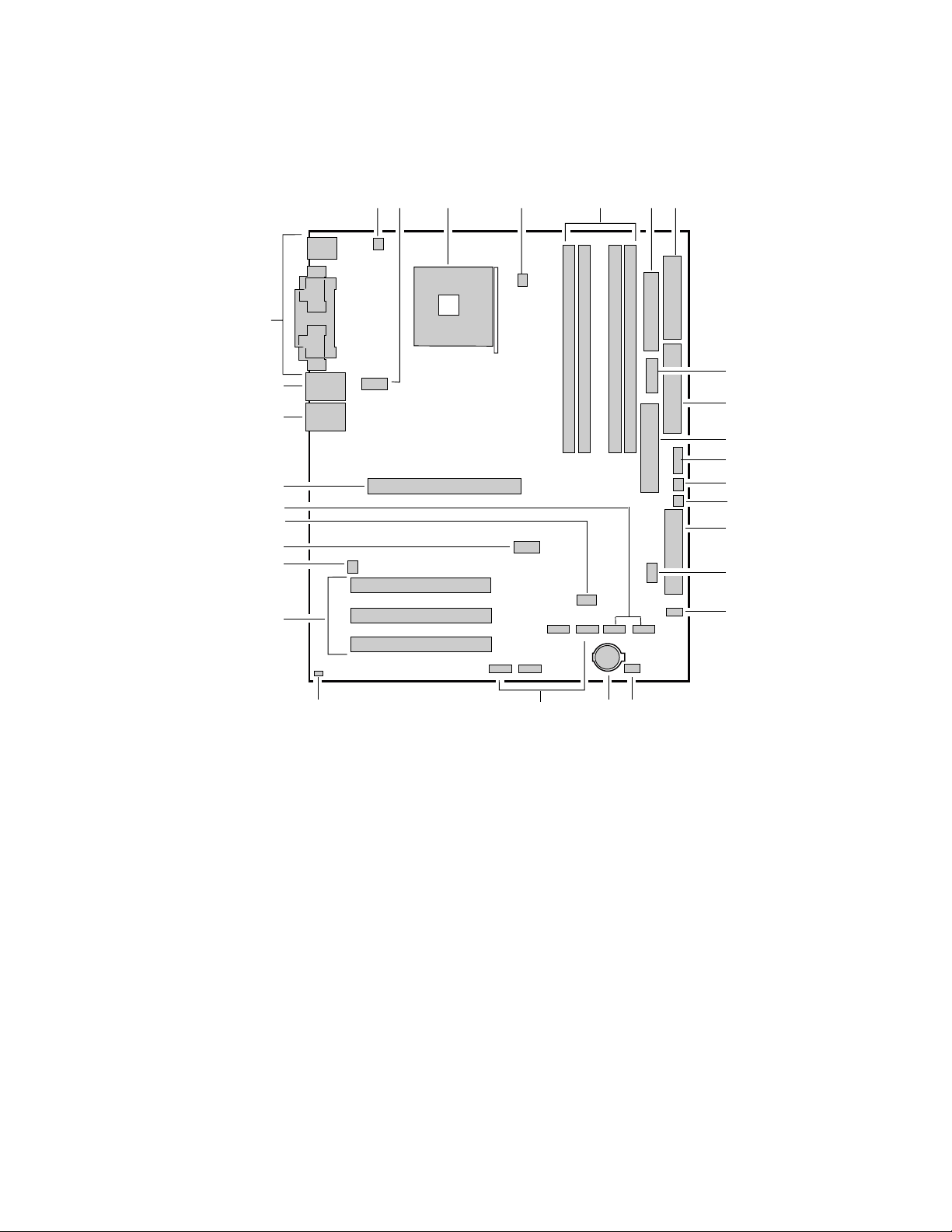
Server Board Connector and Component Locations
A BC D E FG
CC
BB
AA
Z
Y
X
W
V
U
A. System Fan 4 Header
B. +12V CPU Power Connector
C. Processor Socket
D. CPU Fan
E. DIMM Sockets
F. Main Power Connector
G. Floppy Drive Connector
H. Auxiliary Power Connector
I. Primary IDE Connector
J. Secondary IDE Connector
K. Serial B Header
L. System Fan 1 Header
M. System Fan 2 Header
N. Front Panel Connector
O. BIOS Configuration Jumper (J8J2)
P. SCSI LED Header
Q. Hot Swap Backplane Header
Figure 1. Server Board Components
H
I
J
K
L
M
N
O
P
S
QRT
TP00182
R. Battery
S. SATA-A1 through SATA-A4 Connector
(S875WP1LX only, from left to right: SATA-A4,
SATA-A2, SATA-A3, SATA-A1)
T. Chassis Intrusion Header
U. PCI 32/33 Slots 1 – 3
(slots numbered from top to bottom)
V. System Fan 3 Header
W. Front Panel USB Header
X. Clear CMOS Jumper J8G1
Y. SATA-B1 and SATA-B2 Connectors
(slots numbered from left to right)
Z. AGP Connector
AA. NIC2 (10/100 Mb)
BB. NIC1 (1 Gb)
CC. Back Panel I/O Ports
Server Board Features 11
Page 12
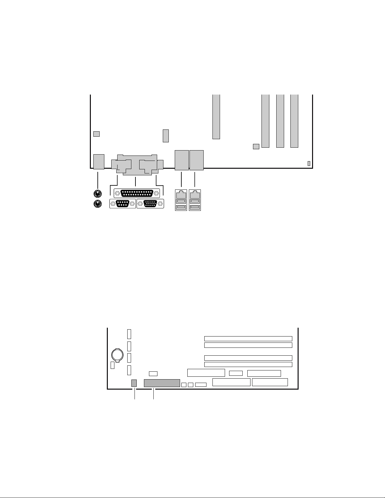
Back Panel Connectors
The back panel connectors are color-coded in compliance with PC 99 recommendations.
C
A
B
DE
A. PS/2 mouse
B. PS/2 keyboard
C. Parallel port
D. Serial port A
E. Video port
FG
HI
Figure 2. Back Panel Connectors
Front Panel Connectors
Figure 3 shows the location of the front panel connectors.
TP00183
F. NIC 1 (1 Gb)
G. NIC 2 (10/100 Mb)
H. USB ports 1 and 2
I. USB ports 3 and 4
AB
A. SCSI LED Header
B. Front Panel Header
TP00184
Figure 3. Front Panel Connectors
12
Page 13

Processor
The S875WP1-E server board supports a single Intel Pentium 4 processor with an mPGA478
socket. The processor connects to the server board through the mPGA478 socket. The Intel
Pentium 4 processor can be removed and replaced to accommodate a supported higher speed
processor.
The server board S875WP1-E supports the following processors.
Table 2. Supported Processors
Type Designation System Bus L2 Cache Size
2.40, 2.60, 2.80, and 3.0 GHz 800 MHz 512 KB Pentium 4 processor with Hyper-
✏
threading (HT) Technology
NOTE
The processor is not included with the server board and must be purchased separately.
3.06 GHz 533 MHz 512 KB
2.0, 2.26, 2.4B, 2.53, 2.66, and
2.80 GHz
2.0, 2.4 GHz 400 MHz 512 KB
533 MHz 512 KB Pentium 4 processor
Memory
The S875WP1-E server board contains four 184-pin DIMM sockets and supports up to four DDR
SDRAM DIMMs. The minimum supported memory configuration is 128 MB and the maximum
configurable memory size is 4 GB with stacked unbuffered DDR266/333/400 ECC DIMMs.
Supported memory configurations are as follows:
• Up to four dual-channel 184-pin Double Data Rate (DDR) SDRAM DIMMs connectors with
gold-plated contacts. Supported memory configuration are:
DDR400: to run DDR400 memory at full speed requires an Intel Pentium 4 processor
with 800 MHz front side bus (FSB) frequency.
DDR333: to run DDR333 memory at full speed requires an Intel Pentium 4 processor
with 533 MHz FSB frequency. DDR333 memory will run at 320 MHz frequency when
using an Intel Pentium 4 processor with 800 MHz FSB frequency.
DDR266: DDR266 memory may only be used with an Intel Pentium 4 processor with
400 MHz or 533 MHz FSB frequency only.
• Support for:
Single-channel memory
Unbuffered, single or double-sided DIMMs
Serial Presence Detect (SPD) memory only
Support for Suspend to RAM (STR), S3 ACPI state
ECC and non-ECC RAM
2.5 V memory
Server Board Features 13
Page 14

• Support for 128 Mb, 256 Mb, and 512 Mb memory technologies for the following memory
configurations:
Up to 1.0 GB utilizing 128 Mb technology
Up to 2.0 GB utilizing 256 Mb technology
Up to 4.0 GB utilizing 512 Mb technology
Only DIMMs tested and qualified by Intel or a designated memory test vendor will be supported on
the S875WP1-E server board. Note that all DIMMs are supported by design, but only fully
qualified DIMMs will be supported. Mixed mode DDR DS-DIMMs (x8 and x16 on the same
DIMM) is not supported. Check the Intel Customer Support website for the latest tested memory
list:
http://support.intel.com/support/motherboards/server/S875WP1-E
Intel 875P Chipset
The Intel 875P chipset consists of the following devices:
• Intel 82875P Memory Controller Hub (MCH) with Accelerated Hub Architecture (AHA) bus
• Intel 82801EB I/O Controller Hub (ICH5) with AHA bus
• Intel 82802AC Firmware Hub (FWH)
The MCH is a centralized controller for the system bus, the memory bus, the AGP bus, and the
Accelerated Hub Architecture interface. The ICH5-R is a centralized controller for the board’s I/O
paths. The FWH provides the nonvolatile storage of the BIOS.
Intel 82875P Memory Controller Hub (MCH)
The MCH supports the data integrity features supported by the Pentium 4 processor bus, including
address, request, and response parity. The 875P chipset always generates ECC data while it is
driving the processor data bus, although the data bus ECC can be disabled or enabled by BIOS. It
is enabled by default. The MCH controls the Intel 82547EI from the CSA interface.
The MCH provides the following:
• An integrated DDR memory controller with auto detection.
• Support for ACPI Rev 2.0 compliant power management.
• AGP 2.0 slot, also known as AGP 8x
14 Intel Server Board S875WP1-E Product Guide
Page 15

Intel 82801EB I/O Controller Hub (ICH5-R)
The Intel 82801EB ICH5-R has these features:
• Upstream Hub Interface to the MCH
• Integrated IDE controller (supports two Ultra ATA-100/66 mode, Ultra DMA 33 mode, and
PIO mode).
• Integrated SATA controller supports two SATA devices with transfer speeds up to 150 MB/s
and independent DMA operation on the two ports
• One USB 2.0-compliant host controller that supports all six USB ports
• SMBus 2.0 interface
• FWH interface
• Support for the Low Pin Count (LPC) interface.
• Integrated LAN controller (Intel 8562ET) for interfacing the ICH5-R LAN connect interface to
the LAN connect component
• 33 MHz Peripheral Component Interface (PCI) Local Bus slots supporting PCI
specification, Rev 2.3.
• Power management logic (ACPI Rev 2.0-compliant).
• Support for two Ultra DMA 33 / ATA 100/66 connectors.
Intel 82802AC Firmware Hub (FWH)
The Intel 82802AC Firmware Hub (FWH) includes an 8 megabit symmetrical flash memory
device. Internally, the device is grouped into eight 64 KB blocks that are individually erasable,
lockable, and unlockable.
The FWH provides the following:
• System BIOS program
• Logic that enables protection for storing and updating of platform information
Video
The server board S875WP1-E contains two separate, mutually exclusive graphics subsystems. You
can use either the AGP connector or the ATI Rage XL video controller. When an AGP card is
installed, the integrated 8 MB video controller is disabled.
Server Board Features 15
Page 16

AGP Connector
AGP is a high-performance interface for graphics-intensive applications. AGP is independent of
the PCI bus and is intended for exclusive use with graphical display devices. The AGP bus follows
the AGP 3.0 specification.
The AGP connector on the server board S875WP1-E supports the following:
• 2X, 4X, or 8X AGP protocol
• 1.5 V add-in cards only
• Maximum bus bandwidth of 2.13 GB/sec
NOTE
✏
The AGP connector is keyed for 1.5 V AGP cards only. Do not attempt to
install a legacy 3.3 V AGP card. The AGP connector is not mechanically
compatible with legacy 3.3 V AGP cards.
ATA Rage XL Video Controller
The S875WP1-E server board provides an ATI Rage XL PCI graphics accelerator, along with
8 MB of video SDRAM and support circuitry for an embedded SVGA video subsystem. The ATI
Rage XL chip contains a SVGA video controller, clock generator, 2D and 3D engine, and
RAMDAC in a 272-pin PBGA. One 2Mx32 SDRAM chip provides 8 MB of video memory.
The SVGA subsystem supports a variety of modes, up to 1600 x 1200 resolution in 8/16/24/32 bpp
modes under 2D, and up to 1024 x 768 resolution in 8/16/24/32 bpp modes under 3D. It also
supports both CRT and LCD monitors up to 100 Hz vertical refresh rate.
The server board S875WP1-E provides a standard 15-pin VGA connector and supports disabling of
the on-board video through the BIOS Setup menu or when a plug-in video card is installed in the
AGP slot or any of the PCI slots.
Video Modes
The Rage XL chip supports all standard IBM* VGA modes. The following table shows the 2D/3D
modes supported for both CRT and LCD. The table specifies the minimum memory requirement
for various display resolution, refresh rates, and color depths.
Table 3. Video Modes
2D Mode
640x480 60, 72, 75, 90, 100 Supported Supported Supported Supported
800x600 60, 70, 75, 90, 100 Supported Supported Supported Supported
1024x768 60, 72, 75, 90, 100 Supported Supported Supported Supported
1280x1024 43, 60 Supported Supported Supported Supported
1280x1024 70, 72 Supported – Supported Supported
Refresh Rate (Hz)
S875WP1-E 2D Video Mode Support
8 bpp 16 bpp 24 bpp 32 bpp
continued
16 Intel Server Board S875WP1-E Product Guide
Page 17

Table 3. Video Modes (continued)
1600x1200 60, 66 Supported Supported Supported Supported
1600x1200 76, 85 Supported Supported Supported –
3D Mode Refresh Rate (Hz) S875WP1-E 3D Video Mode Support with Z Buffer Enabled
640x480 60,72,75,90,100 Supported Supported Supported Supported
800x600 60,70,75,90,100 Supported Supported Supported Supported
1024x768 60,72,75,90,100 Supported Supported Supported Supported
1280x1024 43,60,70,72 Supported Supported – –
1600x1200 60,66,76,85 Supported – – –
Video Memory Interface
The memory controller subsystem of the Rage XL arbitrates requests from direct memory interface,
the VGA graphics controller, the drawing coprocessor, the display controller, the video scalar, and
hardware cursor. Requests are serviced in a manner that ensures display integrity and maximum
CPU/coprocessor drawing performance.
The server board S875WP1-E supports an 8 MB (512Kx32bitx4 Banks) SDRAM device for video
memory.
Super I/O
The SMSC LPC47M172 I/O Controller provides the following features:
• Low pin count (LPC) interface
• 3.3 V operation
• One serial port and one serial port header
• One parallel port with Extended Capabilities Port (ECP) and Enhanced Parallel Port (EPP)
support
• Serial IRQ interface compatible with serialized IRQ support for PCI systems
• PS/2-style mouse and keyboard interfaces
• Interface for one 1.2 MB, 1.44 MB, or 2.88 MB diskette drive
• Intelligent power management, including a programmable wake up event interface
• PCI power management support
The BIOS Setup program provides configuration options for the I/O controller.
Server Board Features 17
Page 18

Serial Port
The server board S875WP1-E has one serial port connector and one serial port header. The serial
port A connector is located on the back panel. The serial ports’ NS16C550-compatible UART
supports data transfers at speeds up to 115.2 kb/s with BIOS support.
A DH10 10-pin serial header is available on the baseboard for an option Serial B port.
Parallel Port
The 25-pin D-Sub parallel port connector is located on the back panel. In the BIOS Setup program,
the parallel port can be set to the following modes:
*
• Output only (PC AT
• Bi-directional (PS/2 compatible)
• EPP
• ECP
-compatible mode)
Floppy Drive Controller
The I/O controller supports one diskette drive that is compatible with the 82077 diskette drive
controller and supports both PC-AT and PS/2 modes.
Keyboard and Mouse Connectors
PS/2 keyboard and mouse connectors are located on the back panel. The +5 V lines to these
*
connectors are protected with a PolySwitch
connection after an overcurrent condition is removed.
✏
NOTE
The keyboard is supported in the bottom PS/2 connector and the mouse is
supported in the top PS/2 connector. Power to the computer should be turned
off before a keyboard or mouse is connected or disconnected.
The keyboard controller contains the AMI keyboard and mouse controller code, provides the
keyboard and mouse control functions, and supports password protection for power-on/reset. A
power-on/reset password can be specified in the BIOS Setup program.
circuit that, like a self-healing fuse, reestablishes the
18 Intel Server Board S875WP1-E Product Guide
Page 19

USB
High-Speed USB 2.0 Support
✏
NOTES
Use a shielded cable that meets the requirements for a full-speed USB
device. Computer systems that have an unshielded cable attached to a USB
port might not meet FCC Class B requirements, even if no device or a lowspeed USB device is attached to the cable.
USB devices are limited to USB 1.1 transfer rates prior to operating system
and driver initialization.
The server board supports up to six USB 2.0 ports via the ICH5. Four ports are routed to the back
panel. One header, supporting up to two ports, is routed to the front panel. USB 2.0 ports are
backward compatible with USB 1.1 devices. USB 1.1 devices will function normally at USB 1.1
speeds.
USB 2.0 support requires both an operating system and drivers that fully support USB 2.0 transfer
rates. Disabling High-Speed USB in BIOS reverts all USB 2.0 ports to USB 1.1 operation. This
may be required to accommodate operating systems that do not support USB 2.0.
Legacy USB Support
Legacy USB support allows USB devices such as keyboard, mice, and hubs to be used even when
the operating system’s USB drivers are not available. Legacy USB support is used to access the
BIOS Setup program, and to install an operating system that supports USB. By default, Legacy
USB support is set to Enabled.
Four of the USB ports are implemented with stacked back panel connectors; the other two are
accessible via the front panel USB header. The S875WP1-E server board fully supports UHCI and
uses UHCI-compatible software drivers.
NOTE
✏
Computer systems that have an unshielded cable attached to a USB port may not
meet FCC Class B requirements, even if no device is attached to the cable. Use
s shielded cable that meets the requirements for full-speed devices.
Server Board Features 19
Page 20

Legacy USB support operates as follows:
1. When the user applies power to the computer, legacy support is disabled.
2. POST begins.
3. Legacy USB support is enabled by the BIOS allowing the user to use a USB keyboard to enter
and configure the BIOS Setup program and the maintenance menu.
4. POST completes.
5. The operating system loads. While the operating system is loading, USB keyboard and mice
are recognized and may be used to configure the operating system. (Keyboard and mice are not
recognized during this period if Legacy USB support is set to Disabled in the BIOS Setup
program.)
6. After the operating system loads the USB drivers, all legacy and non-legacy USB devices are
recognized by the operating system, and Legacy USB support from the BIOS is no longer used.
To install an operating system that supports USB, verify that Legacy USB support in the BIOS
Setup program is set to Enabled and follow the operating system’s installation instructions.
NOTE
✏
Legacy USB support is for keyboard, mice, and hubs only. Other USB
devices are not supported in legacy mode.
PCI I/O Subsystem
The primary I/O bus for the server board S875WP1-E is PCI, with one independent PCI bus. The
PCI bus complies with the PCI Local Bus Specification, Rev 2.3. The PCI bus is directed through
the Intel 82801EB I/O Controller Hub (ICH5-R). The table below lists the characteristics of the
PCI bus.
Table 4. PCI Bus Characteristics
Voltage Width Speed Type Comments
5 V 32-bits 33 MHz Independent Bus Supports full-length cards
32-bit, 33-MHz PCI Subsystem
All 32-bit, 33-MHz PCI I/O for the server board S875WP1-E is directed through the Intel 82801EB
I/O Controller Hub (ICH5-R). The PCI bus supports the following embedded devices and
connectors:
• 2D/3D Graphics Accelerator: ATI Rage XL Video Controller.
• Serial ATA-100 controller: Promise Technology PDC20319.
• Three PCI slots
Each of the embedded devices listed above, with exception to the Ultra DMA 33 / ATA 100/66
connectors, will be allocated a GPIO to disable the device.
20 Intel Server Board S875WP1-E Product Guide
Page 21

Device IDs (IDSEL)
Each device under the PCI hub bridge has its IDSEL signal connected to one bit of AD[31:16],
which acts as a chip select on the PCI bus segment in configuration cycles. This determines a
unique PCI device ID value for use in configuration cycles. The following table shows each
IDSEL value for the PCI bus devices and the corresponding device description.
Table 5. PCI Bus Configuration IDs
IDSEL Value Device
16 PCI slot 1 (closest to AGP connector)
17 PCI slot 2 (middle slot)
18 PCI slot 3 (closest to left edge of board)
22 ATI Rage XL Video Controller
23 Promise Technology PDC20319 ATA-100 controller
Data Storage
Serial ATA (SATA)
The server board S875WP1-E supports Serial ATA devices using the ICH5-R controller. The
ICH-5 provides the following Serial ATA support:
• 150 MB/sec transfer rate
• Up to two SATA devices on the server board S875WP1-E. These are indicated by the
connectors labeled SATA-B1 and SATA-B2 on the server board.
• Support for RAID 0 (Striping) and 1 (Mirroring) is planned, but not currently available.
The server board S875WP1LX supports an additional four Serial ATA devices using the Promise
Technology PDC20319 host controller. These are indicated by the connectors labeled from left to
right on the server board: SATA-A4, SATA-A2, SATA-A3, and SATA-A1. The Promise
PDC20319 controller provides the following Serial ATA support:
• 150 MB/sec transfer rate
• Support for RAID 0 (Striping), 1 (Mirroring), and 10 (Mirroring and Striping).
✏
NOTES
Although the Promise Technology PDC20319 Serial ATA controller on this
product supports up to 150 MB/sec transfer rate, the PCI bus limits some
SATA devices are limited to a maximum of 133 MB/sec.
For instructions on installing and configuring Serial ATA RAID on the 4-port
Promise Controller that is available on the server board S875WP1LX, please see
http://support.intel.com/support/motherboards/server/s875wp1e/sata-install.htm
Server Board Features 21
Page 22

IDE Interfaces
The ICH5-R IDE controller has two independent bus-mastering IDE interfaces that can be
independently enabled. The interface handles the exchange of information between the processor
and peripheral devices like hard disks and CD-ROM drives. The IDE interfaces supports:
• Up to four IDE devices (such as hard drives)
• ATAPI devices (such as CD-ROM drives)
• Laser servo (LS-120) drives
• PIO Mode devices
• Ultra DMA-33: DMA protocol on IDE bus supporting host and target throttling and transfer
rates of up to 33 MB/sec.
• ATA-100/66: DMA protocol on IDE bus supporting host and target throttling and transfer
rates of up to 100 MB/sec. The ATA-100/66 protocol is similar to Ultra DMA and is device
driver compatible.
✏ NOTE
ATA-100/66 is a faster timing and requires a specialized cable to reduce
reflections, noise, and inductive coupling.
The IDE interfaces also support ATAPI devices (such as CD-ROM drives) and ATA devices using
the transfer modes.
The BIOS supports Logical Block Addressing (LBA) and Extended Cylinder Head Sector (ECHS)
translation modes. The drive reports the transfer rate and translation mode to the BIOS.
The S875WP1-E server board supports Laser Servo (LS-120) diskette technology through the IDE
interfaces. An LS-120 drive can be configured as a boot device by setting the BIOS Setup
program’s Boot menu to one of the following:
• ARMD-FDD (ATAPI removable media device – floppy disk drive)
• ARMD-HDD (ATAPI removable media device – hard disk drive)
SCSI Hard Drive Activity LED Connector
The SCSI hard drive activity LED connector is a 1 x 2-pin connector that allows an add-in
SCSI controller to use the same LED as the onboard IDE controller. For proper operation, this
connector should be wired to the LED output of the add-in SCSI controller. The LED indicates
when data is being read from, or written to, both the add-in SCSI controller and the IDE controller.
22 Intel Server Board S875WP1-E Product Guide
Page 23

Network Interface Controller (NIC)
The server board S875WP1-E supports two Network Interface Controllers (NICs), one that runs at
10/100Mb and is based on the Intel 82562ET NIC and the other that runs at one gigabit and is
based on the Intel 82547EI NIC. When looking at the rear of the chassis, the gigabit NIC is at the
left (closest to the video port) and the 10/100Mb NIC is at the right. You can disable either or both
NICs through BIOS Setup.
The 82562ET is controlled by the ICH5-R and supports the following features:
• Integrated IEEE 802.3 10Base-T and 100Base-TX compatible PHY
• IEEE 802.3u auto-negotiation support
• Full duplex support at both 10 Mbps and 100 Mbps operation
• Low power +3.3 V device with reduced power in unplugged mode and automatic detection of
unplugged mode
• 3-port LED support
The 82547EI is controlled by the CSA interface off of the MCH. It supports the following features:
• Basic 10/100/1000 Ethernet LAN connectivity
• Integrated Gigabit Ethernet Media Access Control (MAC) and physical layer (PHY)
• IEEE 802.3 10BASE-T/100BASE-TX/1000BASE-T compliant physical layer interface
• IEEE 802.3ab auto-negotiation support
• Low power (less than 350mW in active transmit mode)
• Reduced power in “unplugged mode” (less than 50mW)
• Automatic detection of “unplugged mode”
• Communication Streaming Architecture (CSA) port provides higher throughput and lower
latencies resulting in up to 30% higher bus throughput (up to wirespeed)
• Full device driver compatibility
• Programmable transit threshold
• Configuration EEPROM that contains the MAC address
• Teaming and Fail over support
NIC Connector and Status LEDs
Two LEDs are built into each RJ-45 LAN connector. For the 82562ET NIC, the yellow LED indicates
a link to the LAN and the green LED indicates the connection speed. Table 6 describes the LED states
when the board is powered up and the 82562ET 10/100 Ethernet LAN subsystem is operating.
Table 6. 10/100 Ethernet LAN Connector LEDs
LED Color LED State Indicates
LED)
Yellow
(right LED)
Server Board Features 23
Off 10 Mbit/sec data rate is selected. Green (left
On 100 Mbit/sec data rate is selected.
Off LAN link is not established.
On (steady state) LAN link is established.
On (brighter and pulsing) The computer is communicating with another computer on the LAN.
Page 24

Table 7 describes the LED states when the board is powered up and the 82547EI 10/100/1000
Gigabit Ethernet LAN subsystem is operating.
Table 7. 10/100/1000 Gigabit Ethernet LAN Connector LEDs
LED Color LED State Indicates
Green (left
LED)
Bi-color LED
(right LED)
Off LAN link is not established.
On (steady state) LAN link is established.
On (brighter and
pulsing)
Off 10 Mbit/sec data rate is selected.
Green 100 Mbit/sec data rate is selected.
Yellow 1000 Mbit/sec data rate is selected.
The computer is communicating with another computer on the LAN.
Power Management
Power management is implemented at several levels, including:
• Software support through Advanced Configuration and Power Interface (ACPI)
• Hardware support:
— Suspend to RAM (Instantly Available PC technology)
— Power connectors
— Fan connectors
— Resume on Ring
— Wake from USB
— Wake from PS/2 keyboard/mouse
— PME# wakeup support
Software Support through ACPI
The Advance Configuration and Power Interface (ACPI)–aware operating system can place the
system into a state where the hard drives spin down, the system fans stop, and all processing is
halted. In this state, the power supply is still on and the processors still dissipate some power, so
the power supply fan and processor fans are still running.
Under ACPI, the operating system directs all system and device power state transitions. The
operating system puts devices in and out of low-power states based on user preferences and
knowledge of how devices are being used by applications. Devices that are not being used can be
turned off. The operating system uses information from applications and user settings to put the
system as a whole into a low-power state.
24 Intel Server Board S875WP1-E Product Guide
Page 25

ACPI features include:
• Plug and Play (including bus and device enumeration)
• Power management control of individual devices, add-in boards (some add-in boards may
require an ACPI-aware driver), video displays, and hard disk drives
• Methods for achieving less than 15-watt system operation in the power-on/standby
sleeping state
• A soft-off feature that enables the operating system to power-off the computer
• Support for multiple wake-up events
• Support for a front panel power and sleep mode switch
The Server Board S875WP1-E supports sleep states S0, S1, S2, S3, S4, and S5. When the server
board is operating in ACPI mode, the operating system retains control of the system and the
operating system policy determines the entry methods and wake-up sources for each sleep state.
Sleep entry and wake-up event capabilities are provided by the hardware but are enabled by the
operating system. The following is a summary of the supported sleep states:
• S0: Normal running state.
• S1: Processor sleep state. No context will be lost in this state and the processor caches will
maintain coherency.
• S3: Suspend to RAM (Instantly Available PC Technology).
• S4: Hibernate or Save to Disk. The memory and machine state are saved to disk. Pressing the
power button or another wake-up event restores the system state from the disk and resumes
normal operation. This state assumes that no hardware changes were made to the system while
it was off.
• S5: Soft off. Only the RTC section of the chipset is running in this state.
CAUTION
The system is off only when the AC power is disconnected.
Table 8 lists the system states based on how long the power switch is pressed, depending on how
ACPI is configured with an ACPI-aware operating system.
Table 8. Effects of Pressing the Power Switch under ACPI
If the system is in this state…
Off
(ACPI S5 – Soft off)
On
(ACPI S0 – working state)
On
(ACPI S0 – working state)
Sleep
(ACPI S1 – sleeping state)
Sleep
(ACPI S1 – sleeping state)
…and the power switch is
pressed for
Less than four seconds Power-on
Less than four seconds Soft-off/Standby
More than four seconds Fail safe power-off
Less than four seconds Wake-up
More than four seconds Power-off
…the system enters this state
(ACPI S0 – working state)
(ACPI S1 – sleeping state)
(ACPI S5 – Soft off)
(ACPI S0 – working state)
(ACPI S5 – Soft off)
Server Board Features 25
Page 26

Wake-up Devices and Events
CAUTION
For LAN wake capabilities, the 5 V standby line for the power supply must
be capable of providing adequate +5 V standby current. Failure to provide
adequate standby current when implementing LAN wake capabilities can
damage the power supply.
Table 9 provides an overview of the devices or events that can wake the computer from specific
states.
Table 9. Wake-up Devices and Events
These devices/events can wake up the computer… …from this state
Power button S1, S3, S4
RTC alarm S1, S3, S4
LAN S1, S3, S4
PCI via PME# signal S1, S3, S4
Resume on Ring (back panel Serial Port A) S1, S3
USB S1, S3
PS/2 S1, S3
Notes:
1. For LAN and PME#, S5 is disabled by default in the BIOS Setup program. Setting this option to Power On will
enable a wake-up event from LAN in the S5 state.
(Note 1)
(Note 1)
(Note 1)
(Note 1)
, S5
, S5
, S5
, S5
NOTE
✏
The use of these wake-up events from an ACPI state requires an operating
system that provides full ACPI support. In addition, software, drivers, and
peripherals must fully support ACPI wake events.
LAN Wake
LAN wake capabilities enable remote wake-up of the computer through a network. The LAN
subsystem PCI bus network adapter monitors network traffic at the Media Independent Interface.
Upon detecting a Magic Packet
*
frame, the LAN subsystem asserts a wake-up signal that wakes up
the computer from ACPI S1, S3, S4, and S5 state.
Depending on the LAN implementation, the S875WP1-E server board supports LAN wake
capabilities with ACPI in the following ways:
• The PCI bus PME# signal for PCI 2.2 compliant LAN designs
• The onboard LAN subsystem
PCI via PME# Wake-up Support
When the PME# signal on the PCI bus is asserted, the computer wakes from an ACPI S1, S3, S4, or
S5 state (with Wake on PME enabled in BIOS).
26 Intel Server Board S875WP1-E Product Guide
Page 27

Resume on Ring
Resume on Ring enables telephony devices to access the computer when it is in a power-managed
state. The operation of Resume on Ring wakes the system from the S1 or S3 sleep states when a
signal is sent to the serial port at the rear or the chassis or to an internally installed modem. Resume
on ring can be summarized as follows:
• Resumes operation from ACPI S1 or S3 states
• Requires only one call to access the computer
• Detects incoming call similarly for external and internal modems
• Requires modem interrupt be unmasked for correct operation
Wake from USB
USB bus activity wakes the computer from an ACPI S1 or S3 state.
NOTE
✏
Wake from USB requires the use of a USB peripheral that supports Wake
from USB.
Wake from PS/2 Devices
PS/2 device activity, such as moving a PS/2 mouse or pressing a key on a PS/2 keyboard, wakes the
computer from an ACPI S1 or S3 state.
Hardware Support
The S875WP1-E server board provides several power management hardware features, including:
• Power connector
• Fan connectors
• Instantly Available PC technology
Instantly Available PC technology and LAN Wake require power from the +5 V standby line. The
sections discussing these features describe the incremental standby power requirements.
CAUTION
Ensure that the power supply provides adequate +5 V standby current if
Instantly Available PC technology features is used. Failure to do so can
damage the power supply. The total amount of standby current required
depends on the wake devices supported and manufacturing options.
Server Board Features 27
Page 28

Power Connector
When used with an ATX12V or EPS12V compliant power supply that supports remote power
on/off, the S875WP1-E server board can turn off the system power through software control.
When the system BIOS receives the correct command from the operating system, the BIOS turns
off power to the computer.
With soft-off enabled, if power to the computer is interrupted by a power outage or a disconnected
power cord, when power resumes, the computer returns to the power state it was in before power
was interrupted (on or off). The computer’s response can be set using the After Power Failure
feature in the BIOS Setup program’s Boot menu.
NOTE
✏
A standard ATX 20 pin power connector and standard ATX 12V 4-pin 2x2
connector can be used to power the S875WP1-E board. Plug the power
cables into the pin 1 end of their respective motherboard connectors, leaving
pins 21-24 unused on the main power connector and 5-8 unused on the 12V
connector.
Fan Connectors
Table 10 summarizes the function/operation of the fan connectors.
Table 10. Fan Connector Function/Operation
Connector Description
Processor fan (CPU
FAN)
Front and rear chassis
fans (FAN1, FAN2,
FAN3, and FAN4)
• +12 V DC connection for a processor fan or active fan heat sink.
• Fan is on in the S0 or S1 state.
Fan is off when the system is off or in the S3, S4, or S5 state.
• Wired to a fan tachometer input of the Hardware Management ASIC.
• +12 V DC connection for a system or chassis fan.
• Fan is on in the S0 or S1 state.
Fan is off when the system is off or in the S3, S4, or S5 state.
• Wired to a fan tachometer input of the Hardware Management ASIC (Fans 1, 2,
and 4 only).
28 Intel Server Board S875WP1-E Product Guide
Page 29
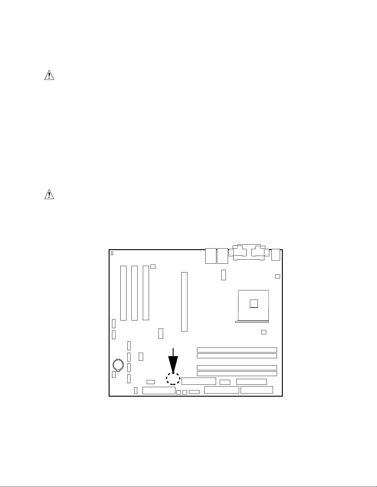
Instantly Available PC Technology
CAUTION
For Instantly Available PC technology, the +5 V standby line for the power
supply must be capable of providing adequate +5 V standby current. Failure
to provide adequate standby current when implementing Instantly Available
PC technology can damage the power supply.
The S875WP1-E server board supports the PCI Bus Power Management Interface Specification.
An add-in board that supports this specification can participate in power management and can be
used to wake the computer.
The use of Instantly Available PC technology requires operating system support and PCI 2.2
compliant add-in cards and drivers.
The standby power indicator LED shows that power is still present even when the computer
appears to be off. Figure 4 shows the location of the standby power indicator LED.
CAUTION
If AC power has been switched off and the standby power indicator is still lit,
disconnect the power cord before installing or removing any devices
connected to the board. Failure to do so could damage the board and any
attached devices.
CR7J1
TP00185
Figure 4. Location of the Standby Power Indicator LED CR7J1
Server Board Features 29
Page 30

Hardware Management and Monitoring
The Hardware Management features enable the board to be compatible with the Wired for
Management (WfM) specification. The board has several hardware management features,
including the following:
• Remote temperature sensing near the Vreg
• Power supply monitoring (+5 V, +3.3 V, 3.3 VSB, +1.5 V, and VCCP) to detect levels above
or below acceptable values
• Fan monitoring though four fan tachometer inputs. Monitoring can be implemented using
LANDesk
• Chassis intrusion detection
The server board S875WP1-E has an integrated Hardware Management ASIC that is responsible
for hardware monitoring. Together, the Hardware Management ASIC and the LANDesk Client
Manager (LDCM) 6.3 software provide basic server hardware monitoring that alerts a system
administrator if a hardware problem occurs on an Intel Server Board S875WP1-E based system.
The LDCM software is for use with Windows 2000 Server and Windows 2000 Advanced Server
operating systems. Other operating systems, such as Red Hat
LDCM.
*
Client Manager or other third-party software.
*
Linux* are not be monitored with
Intel LANDesk Client Manager software and user guides that provide more information on using
Intel LDCM software are available on the Intel Server Board S875WP1-E Resource CD and are
also available for download at:
http://www.support.intel.com/support/motherboards/server/S875WP1-E
Chassis Intrusion and Detection
The server board S875WP1-E supports a chassis security feature that detects the removal of the
chassis cover. For the chassis intrusion circuit to function, the chassis’ power supply must be
connected to AC power. The security feature uses a mechanical switch on the chassis that attaches
to the chassis intrusion connector. Chassis intrusion options can be configured through the BIOS
Setup screens.
NOTE
✏
Chassis intrusion detection may be implemented using LANDesk Client
Manager or third-party software.
30 Intel Server Board S875WP1-E Product Guide
Page 31

Password Security
The BIOS includes security features that restrict whether the BIOS Setup program can be accessed
and who can boot the server. A supervisor password and a user password can be set for the Setup
menu and for booting the server, with the following restrictions:
• The supervisor password gives unrestricted access to view and change all Setup options. If
only the supervisor password is set, pressing <Enter> at the password prompt of Setup gives the
user restricted access to Setup.
• If both the supervisor and user passwords are set, you must enter either the supervisor password
or the user password to access Setup. Setup options are then available for viewing and
changing depending on whether the supervisor or user password was entered.
• Setting a user password restricts who can boot the server. The password prompt is displayed
before the server is booted. If only the supervisor password is set, the server boots without
asking for a password. If both passwords are set, you can enter either password to boot
the server.
Table 11. Supervisor and User Password Functions
Password Set
Neither Can change all
Supervisor
only
User only N/A Can change all
Supervisor
and user set
Note: If no password is set, any user can change all Setup options.
Supervisor
Mode
options
Can change all
options
Can change all
options
(Note)
User Mode Setup Options
Can change all
options
Can change a
limited number
of options
options
Can change a
limited number
of options
(Note)
None None None
Supervisor Password Supervisor None
Enter Password
Clear User Password
Supervisor Password
Enter Password
Password to
Enter Setup
User User
Supervisor or
user
Password
During Boot
Supervisor or
user
Server Board Features 31
Page 32
Real-Time Clock, CMOS SRAM, and Battery
The real-time clock provides a time-of-day clock and a multi-century calendar with alarm features.
The real-time clock supports 256 bytes of battery-backed CMOS SRAM in two banks that are
reserved for BIOS use.
A coin-cell battery (CR2032) powers the real-time clock and CMOS memory. When the computer
is not plugged into a wall socket, the battery has an estimated life of three years. When the
computer is plugged in, the standby current from the power supply extends the life of the battery.
The clock is accurate to ± 13 minutes/year at 25 ºC with 3.3 VSB applied.
The time, date, and CMOS values can be specified in the BIOS Setup program. The CMOS values
can be returned to their defaults by using the BIOS Setup program.
✏ NOTE
If the battery and AC power fail, custom defaults, will be loaded into CMOS
RAM at power-on if they defaults have been previously saved.
Recovering the CMOS
In the unlikely event that the CMOS should be corrupt, it can be cleared by using a jumper setting
on the server board. To recover the CMOS and return the settings to the default value:
1. Power down the server and unplug all AC power cables.
2. Remove the cover from the chassis.
3. Move the jumper at jumper block J8G1 to cover pins 2 and three. For the location of jumper
block J8G1, see the figure below.
J8G1
312
TP00200
Figure 5. Location of Clear CMOS Jumper
32 Intel Server Board S875WP1-E Product Guide
Page 33

4. Reattach the AC power cables and power on the server.
5. Power down the server and again remove all AC power cables.
6. Replace the jumper at jumper block J8G1 so that it covers pins 1 and 2.
7. Replace the chassis cover and re-attach the AC power cables.
8. Power on the server.
9. Reconfigure settings as necessary.
BIOS
The S875WP1-E server board uses an Intel/AMI BIOS that is stored in the Firmware Hub (FWH)
and can be updated using a disk-based program. The FWH contains the BIOS Setup program,
POST, the PCI auto-configuration utility, and Plug and Play support.
The S875WP1-E server board supports system BIOS shadowing, allowing the BIOS to execute
from 64-bit onboard write-protected system memory.
The BIOS displays a message during POST identifying the type of BIOS and a revision code. The
initial production BIOS is identified as WP87510A.86B.
When the S875WP1-E server board’s jumper is set to configuration mode and the server is
powered-up, the BIOS compares the processor version and the microcode version in the BIOS and
reports if the two match.
PCI Auto Configuration
The BIOS can automatically configure PCI devices. PCI devices may be onboard or add-in cards.
Auto configuration lets a user insert or remove PCI cards without having to configure the system.
When a user turns on the system after adding a PCI card, the BIOS automatically configures
interrupts, the I/O space, and other system resources. Any interrupts set to Available in Setup are
considered to be available for use by the add-in card. Auto configuration information is stored in
ESCD format.
IDE Auto Configuration
If you select Auto in the BIOS Setup program, the BIOS automatically sets up the two
IDE connectors with independent I/O channel support. The IDE interface supports hard drives up
to ATA-66/100 and recognizes any ATAPI compliant devices, including CD-ROM drives, tape
drives, and Ultra DMA drives.
The BIOS determines the capabilities of each drive and configures them to optimize capacity and
performance. To take advantage of the high capacities typically available today, hard drives are
automatically configured for Logical Block Addressing (LBA) and to PIO Mode 3 or 4, depending
on the capability of the drive. You can override the auto-configuration options by specifying
manual configuration in the BIOS Setup program.
Server Board Features 33
Page 34

To use ATA-66/100 features the following items are required:
• An ATA-66/100 peripheral device
• An ATA-66/100 compatible cable
• ATA-66/100 operating system device drivers
NOTE
✏
ATA-66/100-compatible cables are backward-compatible with drives using slower
IDE transfer protocols. If an ATA-66/100 disk drive and a disk drive using any
other IDE transfer protocol are attached to the same cable, the maximum transfer
rate between the drives is reduced to that of the slowest device.
BIOS Updates
The BIOS can be updated with the Intel® Flash Memory Update Utility. This utility is available on
®
the Intel World Wide Web site. The Intel
boot diskette and manual rebooting of the system. With this utility, the BIOS can be updated from
a file on a 1.44 MB diskette (from a legacy diskette drive or an LS-120 diskette drive) or from a
CD-ROM disk.
Flash Memory Update Utility requires creation of a
This utility support the following BIOS maintenance functions:
• Verifies that the updated BIOS matches the target system to prevent accidentally installing an
incompatible BIOS.
• Updates both the BIOS boot block and the main BIOS. This process is fault tolerant to prevent
boot block corruption.
• Updates the BIOS boot block separately.
• Changes the language section of the BIOS.
• Updates replaceable BIOS modules, such as the video BIOS module.
• Inserts a custom splash screen.
NOTE
✏
Review the instructions distributed with the upgrade utility before attempting
a BIOS update.
Language Support
The BIOS Setup program and help messages are supported in two languages: US English and
Spanish. Additional languages may be flashed in if desired (German, Italian, and French available).
The default language of US English is used unless another language is selected in the BIOS Setup
program.
34 Intel Server Board S875WP1-E Product Guide
Page 35

Custom Splash Screen
During POST, an Intel splash screen is displayed by default. This splash screen can be replaced
with a custom splash screen. A utility is available from Intel to assist with creating a custom splash
screen. The custom splash screen can be programmed into the flash memory using the BIOS
upgrade utility. Information about this capability is available on the Intel Support World Wide
Web site.
Recovering BIOS Data
Some types of failure can destroy the BIOS. For example, the data can be lost if a power outage
occurs while the BIOS is being updated in flash memory. The BIOS can be recovered from a
diskette using the BIOS recovery mode. When recovering the BIOS, be aware of the following:
• Because of the small amount of code available in the non-erasable boot block area, there is no
video support. The user can only monitor this procedure by listening to the speaker or looking
at the diskette drive LED.
• The recovery process may take several minutes; larger BIOS flash memory devices require
more time.
• Two beeps and the end of activity in the diskette drive indicate successful BIOS recovery.
• A series of continuous beeps indicates a failed BIOS recovery.
To create a BIOS recovery diskette, a bootable diskette must be created and the BIOS update files
copied to it. BIOS upgrades and the Intel Flash Memory Update Utility are available from Intel
Customer Support through the Intel World Wide Web site.
NOTE
✏
Even if the computer is configured to boot from an LS-120 diskette, the BIOS
recovery diskette must be a standard 1.44 MB diskette, not a 120 MB diskette.
Boot Options
In the BIOS Setup program, the user can choose to boot from a diskette drive, a hard drive, a
CD-ROM drive, or the network. The default setting is for the diskette drive to be the first boot
device, the hard drive second, and the ATAPI CD-ROM third. The fourth device is disabled.
CD-ROM and Network Boot
Booting from CD-ROM is supported in compliance with the El Torito bootable CD-ROM format
specification. Under the Boot menu in the BIOS Setup program, ATAPI CD-ROM is listed as a
boot device. Boot devices are defined in priority order. Accordingly, if there is not a bootable CD
in the CD-ROM drive, the system will attempt to boot from the next defined drive.
The network can be selected as a boot device. This selection allows booting from the on-board NIC
or a network add-in card with a remote boot ROM installed.
Server Board Features 35
Page 36

Booting Without Attached Devices
For use in embedded applications, the BIOS has been designed so that after passing the POST, the
operating system loader is invoked even if the following devices are not present:
• Video adapter
• Keyboard
• Mouse
Fast Booting Systems with Intel® Rapid BIOS Boot
These factors affect system boot speed:
• Selecting and configuring peripherals properly
• Using an optimized BIOS, such as the Intel Rapid BIOS
Intel Rapid BIOS Boot
Using the following BIOS Setup program settings reduces the POST execution time. In the Boot Menu:
• Set the hard disk drive as the first boot device. As a result, the POST does not first seek a
diskette drive, which saves about one second from the POST execution time.
• Disable Quiet Boot, which eliminates display of the logo splash screen. This could save several
seconds of painting complex graphic images and changing video modes.
• Enabled Intel
diskette drive.
®
Rapid BIOS Boot. This feature bypasses memory count and the search for a
✏
NOTE
It is possible to optimize the boot process to the point where the system boots
so quickly that the Intel logo screen (or a custom logo splash screen) will not
be seen. Monitors and hard disk drives with minimum initialization times
can also contribute to a boot time that might be so fast that necessary logo
screens and POST messages cannot be seen.
This boot time may be so fast that some drives might be not be initialized at
all. If this condition should occur, it is possible to introduce a programmable
delay ranging from three to 30 seconds (using the Hard Disk Pre-Delay
feature of the Advanced Menu in the Drive Configuration Submenu of the
BIOS Setup program).
36 Intel Server Board S875WP1-E Product Guide
Page 37

System Management BIOS (SMBIOS)
SMBIOS is a Server Management Interface (DMI) compliant method for managing computers in a
managed network.
The main component of SMBIOS is the Management Information Format (MIF) database, which
contains information about the computing system and its components. Using SMBIOS, a system
administrator can obtain the system types, capabilities, operational status, and installation dates for
system components. The MIF database defines the data and provides the method for accessing this
information. The BIOS enables applications such as third-party management software to use
SMBIOS.
The BIOS stores and reports the following SMBIOS information:
• BIOS data, such as the BIOS revision level
• Fixed-system data, such as peripherals, serial numbers, and asset tags
• Resource data, such as memory size, cache size, and processor speed
• Dynamic data, such as event detection and error logging
Non-Plug and Play operating systems, such as Windows NT
obtaining the SMBIOS information. The BIOS supports an SMBIOS table interface for such
operating systems. Using this support, an SMBIOS service-level application running on a
non-Plug and Play operating system can obtain the SMBIOS information.
*
, require an additional interface for
Server Board Features 37
Page 38

Page 39

2 Server Board Installation and Upgrades
Tools and Supplies Needed
• Phillips* (cross head) screwdriver (#1 bit and #2 bit)
• Jumper removal tool or needle nosed pliers
• Pen or pencil
• Antistatic wrist strap and conductive foam pad (recommended)
Before You Begin
Emissions Disclaimer
To ensure EMC compliance with your local regional rules and regulations, the final configuration
of your end system product may require additional EMC compliance testing. For more information
please contact your local Intel Representative.
See “Regulatory and Integration Information” on page 107 for product Safety and EMC regulatory
compliance information. This is an FCC Class A device. Integration of it into a Class B chassis
does not result in a Class B device.
Warnings and Cautions
These warnings and cautions apply throughout this chapter. Only a technically qualified person
should configure the server board.
WARNING
Hazardous conditions, devices & cables: Hazardous electrical
conditions may be present on power, telephone, and communication cables.
Turn off the server and disconnect the power cord, telecommunications
systems, networks, and modems attached to the server before opening it.
Otherwise, personal injury or equipment damage can result.
Server Board Installation and Upgrades 39
Page 40

CAUTIONS
System power on/off: The power button DOES NOT turn off the system
AC power. To remove power from system, you must unplug the AC power
cord from the wall outlet. Make sure the AC power cord is unplugged before
you open the chassis, add, or remove any components.
Electrostatic discharge (ESD) & ESD protection: ESD can damage
disk drives, boards, and other parts. We recommend that you perform all
procedures in this chapter only at an ESD workstation. If one is not
available, provide some ESD protection by wearing an antistatic wrist strap
attached to chassis groundany unpainted metal surfaceon your server
when handling parts.
ESD and handling boards: Always handle boards carefully. They can
be extremely sensitive to ESD. Hold boards only by their edges. After
removing a board from its protective wrapper or from the server, place the
board component side up on a grounded, static free surface. Use a
conductive foam pad if available but not the board wrapper. Do not slide
board over any surface.
Installing or removing jumpers: A jumper is a small plastic encased
conductor that slips over two jumper pins. Some jumpers have a small tab on
top that you can grip with your fingertips or with a pair of fine needle nosed
pliers. If your jumpers do not have such a tab, take care when using needle
nosed pliers to remove or install a jumper; grip the narrow sides of the
jumper with the pliers, never the wide sides. Gripping the wide sides can
damage the contacts inside the jumper, causing intermittent problems with
the function controlled by that jumper. Take care to grip, but not squeeze,
with the pliers or other tool you use to remove a jumper, or you may bend or
break the stake pins on the board.
40 Intel Server Board S875WP1-E Product Guide
Page 41
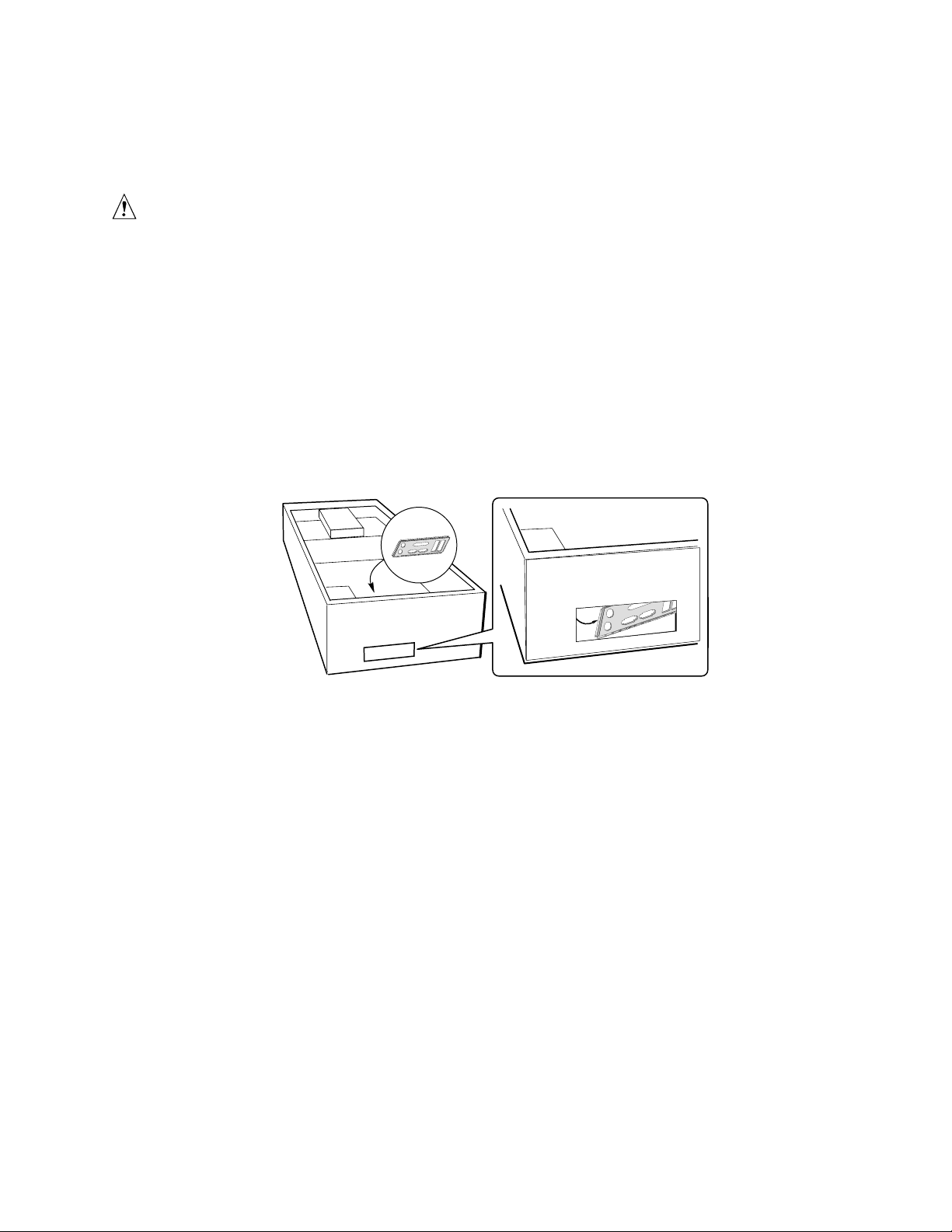
Installing the I/O Shield
CAUTION
Systems based on the S875WP1-E server board need the I/O shield properly
installed to pass emissions (EMI) certification testing and to meet Class A
emissions compliance levels. Without the I/O shield, or with an improperly
installed I/O shield, the server system will not meet Class A regulatory
compliance requirements.
The boxed server board comes with an I/O shield for a general-purpose chassis. When installed in
the chassis, the shield blocks radio frequency transmissions, protects internal components from dust
and foreign objects, and promotes correct airflow within the chassis.
Install the I/O shield before installing the server board in the chassis. Place the shield inside the
chassis and press the shield into place so that it fits tightly and securely. If the shield does not fit,
obtain a proper-sized shield from the chassis supplier.
Figure 6. Installing the I/O Shield
TP00186
Server Board Installation and Upgrades 41
Page 42

Installing Chassis Standoffs
If your chassis does not have standoffs placed as shown below, you must rearrange them so they
match the holes in the server board. Failure to properly rearrange the metal standoffs may cause the
server board to malfunction and may permanently damage it. Your chassis may be different from
the illustration.
Intel Server Chassis SC5200
The chassis comes with standoffs installed in positions 1, 4, 6, 20, 23, and 26. Install standoffs in
the bottom of the chassis at positions 7, 10, 13, 17, 18, and 19. Standoffs are included with your
chassis.
1
4
6
10
13
7
17
18
19
TP00187
Figure 7. Installing Chassis Standoffs in the SC5200 Chassis
42 Intel Server Board S875WP1-E Product Guide
Page 43

Intel® Server Chassis SC5250-E
The Intel® Server Chassis SC5250-E comes with standoffs pre-installed in positions K, E, A, N, I,
and D. Install standoffs in the bottom of the chassis at positions L, 3, 1, M, H, and C. Standoffs are
included with your chassis.
K
E
A
L
M
H
3
C
1
TP00188
Figure 8. Installing Chassis Standoffs in the SC5250-E Chassis
Server Board Installation and Upgrades 43
Page 44

Installing the Server Board
Placing the Server Board into the Chassis
When placing the board into the chassis, insert the rear I/O connector end first, carefully
positioning the board’s I/O connectors into the openings in the I/O shield on the back of the chassis.
Figure 9. Placing the Server Board into the Chassis
Attaching the Server Board
NOTES
✏
You will need a Phillips (#2 bit) screwdriver.
Refer to Page 107 for regulatory requirements and installation instructions
and precautions.
The Intel® Server Chassis SC5200 and the Intel Server Chassis SC5250-E use
different screws to attach the server board to the chassis. Be sure to use the
appropriate screw for your chassis. See the diagram below for the correct
screw for each chassis.
WARNING
Only qualified technical personnel should attempt this procedure. Disconnect
the server from its power source before performing the procedures described
here. Failure to disconnect the power before you open the server can result in
personal injury or equipment damage.
TP00103
44 Intel Server Board S875WP1-E Product Guide
Page 45

Using the screws that came with your chassis, mount the board to the chassis at the 9 locations
shown in Figure 10.
SC5200
SC5250-E
TP00189
Figure 10. Attaching the Server Board
Installing the Processor
To install a processor, follow these instructions:
1. Observe the safety and ESD precautions at the beginning of this chapter.
2. Locate the processor socket and raise the socket handle completely (see Figure 11, B).
3. Aligning the pins of the processor with the socket, insert the processor into the socket
(see Figure 11, A and C).
4. Close the handle completely (see Figure 11, D).
D
B
C
A
Figure 11. Installing the Processor in the Processor Socket
OM14263
Server Board Installation and Upgrades 45
Page 46

✏
NOTE
The bottom of the heat sink may have thermal interface material (TIM)
already applied. Be careful not to damage the thermal interface material.
5. If there is no thermal interface material on the bottom of the heat sink, use the enclosed syringe
and apply the thermal interface material to the top of the processor.
6. Place the fan heat sink on top of the processor.
TP00208
Figure 12. Attaching the Heat Sink to the Processor
46 Intel Server Board S875WP1-E Product Guide
Page 47

7. Fully open the levers at the top of the heat sink, as shown by letter “A” in the figure below.
8. With the levers in their fully opened position, push down firmly to secure the retention
mechanism clips, represented by letter “B” in the figure below.
A
A
B
TP00209
Figure 13. Attaching the Fan Heat Sink Clips to the Processor Socket
9. Firmly push the levers closed. It may be necessary to exert pressure to close the levers. See
Figure 14.
TP00206
Figure 14. Attaching the Fan Heat Sink Clips to the Processor Socket
Server Board Installation and Upgrades 47
Page 48
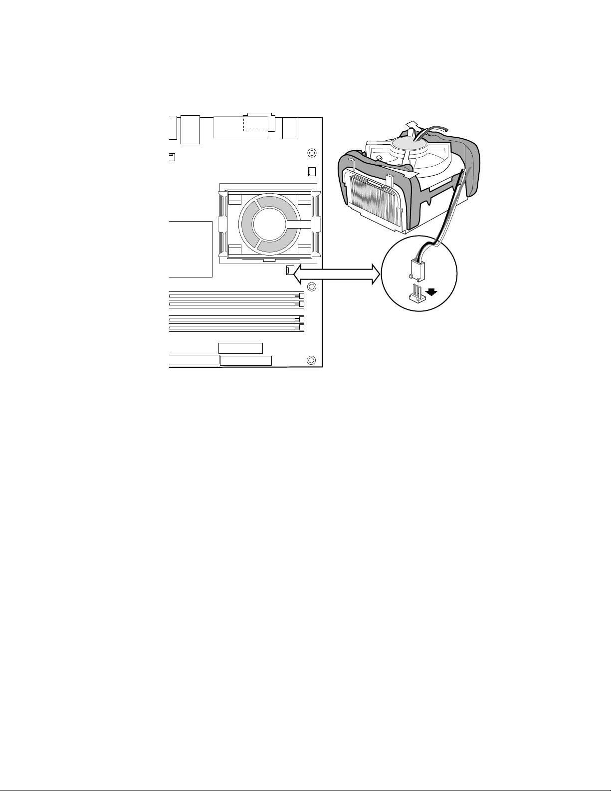
10. Connect the processor fan cable to the processor fan connector (see Figure 15).
Figure 15. Connecting the Processor Fan Cable to the Processor Fan Connector
Removing the Processor
To remove the processor, follow these instructions:
1. Observe the safety and ESD precautions at the beginning of this chapter.
2. Disconnect the processor fan cable.
3. Open the levers on the heat sink.
4. Disengage the retention mechanism hooks at the bottom of the heat sink.
5. Lift the heat sink from the processor.
6. Lift the processor lever.
7. Remove the processor.
TP00201
48 Intel Server Board S875WP1-E Product Guide
Page 49

Installing and Removing Memory
The S875WP1-E server board contains four 184-pin DIMM sockets and supports up to four DDR
SDRAM DIMMs. The minimum supported memory configuration is 128 MB, using one DIMM in
DIMM socket 1A. The maximum configurable memory size is a 4 GB, using four 1 GB stacked
unbuffered DDR266/333/400 ECC DIMMs.
The silkscreen on the board for the DIMMs displays DIMM1A, DIMM2A, DIMM1B, and
DIMM2B, starting from the inside of the board. The DIMM1A is the socket closest to the
processor socket. One, two, or four DIMMs may be used at a time.
For dual-channel interleave, a minimum of two DIMMs must be installed and the DIMMs must be
populated as follows:
• DIMM1A and DIMM 1B: Populate these two sockets together first
• DIMM 2A and DIMM 2B: Populate these sockets in addition to DIMM 1A and DIMM 2A if
four DIMMs are to be used
When four DIMMs are installed, the system will use dual-channel interleave. For single-channel
memory, a single DIMM can be installed in socket DIMM 1A. For single-channel memory using
two DIMMs, populate the DIMM sockets in the following order:
• DIMM1A: Populate this socket if a single DIMM is to be installed
• DIMM2A: Populate this socket and the DIMM1A socket if two DIMMs are to be used
Check the Intel Customer Support website for the latest tested memory list:
http://support.intel.com/support/motherboards/server/S875WP1-E
DIMM Installation Guidelines
All memory components and DIMMs used with the server board S875WP1-E must comply with
the DDR specifications.
Server Board Installation and Upgrades 49
Page 50
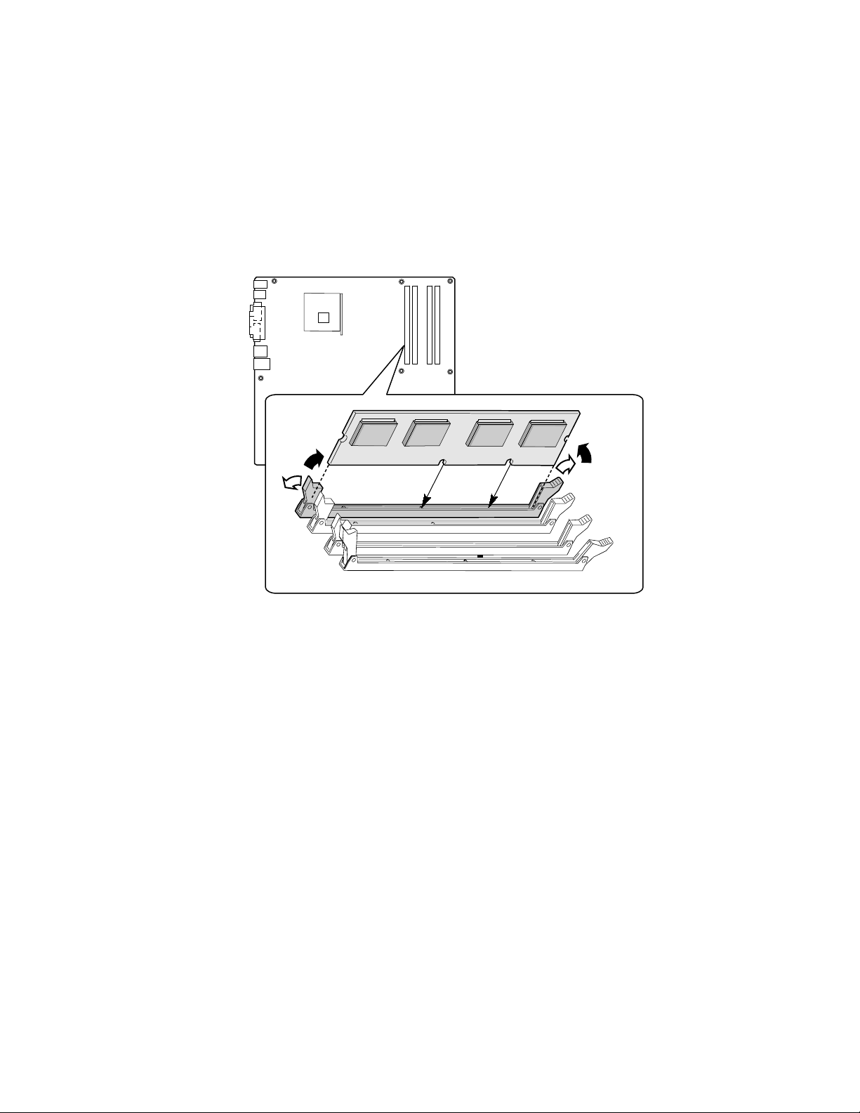
Installing DIMMs
To install DIMMs, follow these steps:
1. Observe the safety and ESD precautions at the beginning of this chapter.
2. Turn off all peripheral devices connected to the server. Turn off the server and disconnect the
AC power cord.
3. Remove the server’s cover and locate the DIMM sockets (see Figure 16).
3
1
2
3
1
TP00190
Figure 16. DIMM Socket Locations
4. Make sure the clips at either end of the DIMM socket(s) are pushed outward to the open
position.
5. Holding the DIMM by the edges, remove it from its anti-static package.
6. Position the DIMM above the socket. Align the two small notches in the bottom edge of the
DIMM with the keys in the socket (see inset in Figure 16).
7. Insert the bottom edge of the DIMM into the socket.
8. When the DIMM is inserted, push down on the top edge of the DIMM until the retaining clips
snap into place. Make sure the clips are firmly in place.
9. Replace the server’s cover and reconnect the AC power cord.
50 Intel Server Board S875WP1-E Product Guide
Page 51

Removing DIMMs
To remove a DIMM, follow these steps:
1. Observe the safety and ESD precautions at the beginning of this chapter.
2. Turn off all peripheral devices connected to the server. Turn off the server.
3. Remove the AC power cord from the server.
4. Remove the server’s cover.
5. Gently spread the retaining clips at each end of the socket. The DIMM pops out of the socket.
6. Hold the DIMM by the edges, lift it away from the socket, and store it in an anti-static package.
7. Reinstall and reconnect any parts you removed or disconnected to reach the DIMM sockets.
8. Replace the server’s cover and reconnect the AC power cord.
Installing and Removing an AGP Card
CAUTION
When installing any AGP card in the server board, ensure that it is fully
seated in the AGP connector before you power on the system. If the card is
not fully seated in the AGP connector, an electrical short may result across
the AGP slot pins. Depending on the over-current protection of the power
supply, certain board components and/or traces may be damaged.
✏
NOTE
The AGP connector is keyed for 1.5 V AGP cards only. Do not attempt to
install a legacy 3.3 V AGP card. The AGP connector is not mechanically
compatible with legacy 3.3 V AGP cards.
The AGP connector supports 1.5 V 8X, 4X, and 2X AGP cards. The server board has an integrated
AGP card retention mechanism (RM).
Server Board Installation and Upgrades 51
Page 52
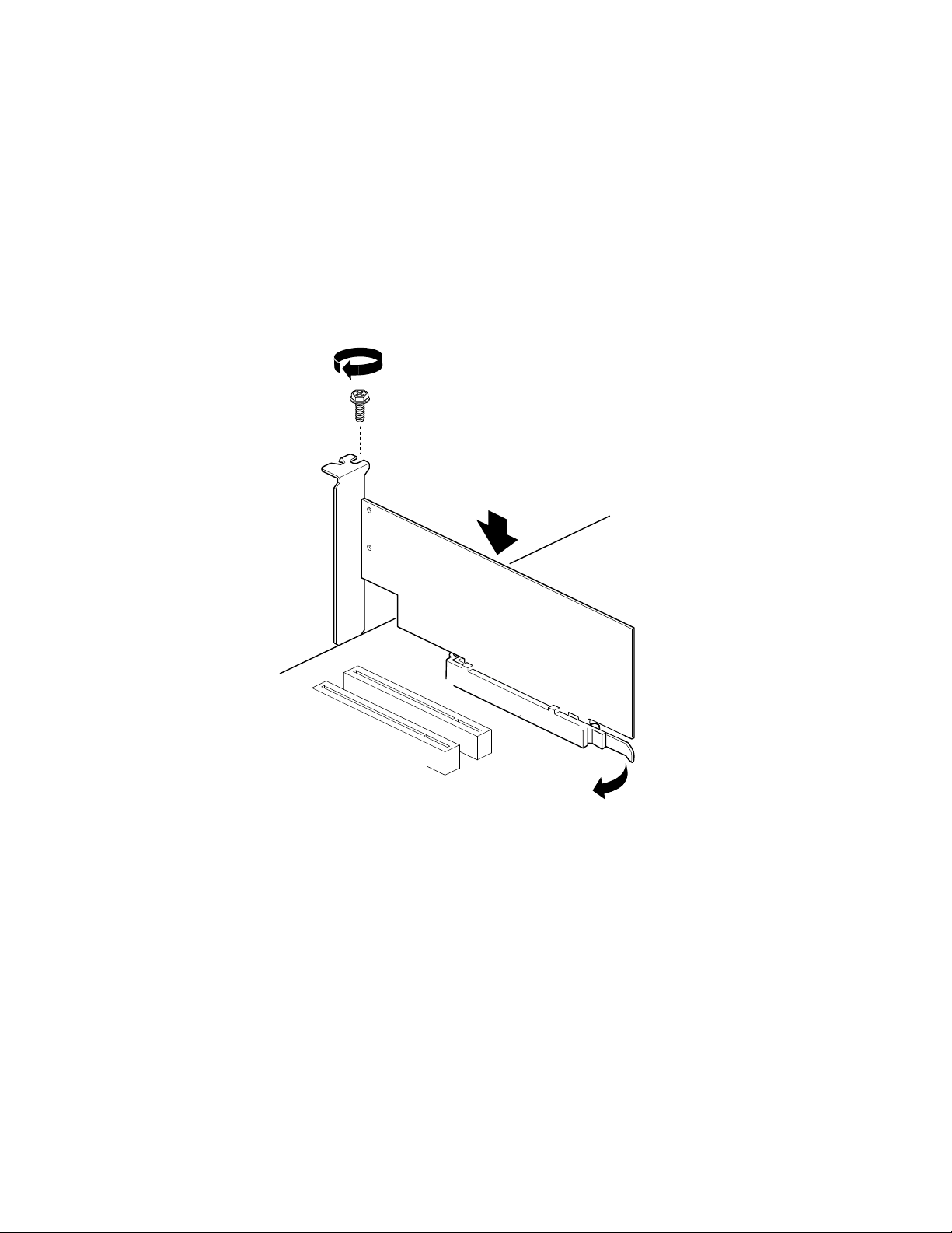
Installing an AGP Card
Follow these instructions to install an AGP card:
1. Observe the precautions in "Before You Begin" on page 39.
2. Place the card in the AGP connector.
3. Press down on the card until it is fully seated in the AGP connector. A retention notch on the
card will snap into place around the retention pin on the lever that is marked “A” in the figure
below.
4. Secure the card’s metal bracket to the chassis back panel with a screw.
A
TP00191
Figure 17. Installing the AGP Card
Removing the AGP Card
Follow these instructions to remove the AGP card from the server board:
1. Observe the precautions in "Before You Begin" on page 39.
2. Remove the screw that secures the card’s metal bracket to the chassis back panel.
3. Pull back on the retention mechanism lever (marked “A” in the figure above to release the
retention pin from the notch in the card.
4. Pull straight up on the card to pull it from the socket.
52 Intel Server Board S875WP1-E Product Guide
Page 53

Connecting the IDE Cable
The Intel® boxed server board package includes a 40-contact, 80-conductor IDE cable. This cable is
capable of connecting two drives to the server board. The cable supports Ultra ATA/100/66 and
Ultra ATA/100 transfer protocols and is backward-compatible with drives using slower IDE
transfer protocols.
✏
NOTE
ATA-66/100 cables are backward compatible with drives using slower IDE
transfer protocols. If an ATA-66/100 disk drive and a disk drive using any
other IDE transfer protocol are attached to the same cable, the maximum
transfer rate between the drives may be reduced to that of the slowest drive.
Do not connect an ATA device as a slave on the same IDE cable as an
ATAPI master device. For example, do not connect an ATA hard drive as a
slave to an ATAPI CD-ROM drive.
For the cable to function correctly:
• Attach the end of the cable that has a single connector (A) to the server board as shown in
Figure 18. The connector at this end of the cable is black and is labeled PRI IDE.
• Attach the end of the cable that has two closely spaced connectors (B) to the drive(s). The
connectors at this end of the cable are gray and black and are labeled P2 and P3.
• If connecting only one IDE drive, connect the drive to the gray connector (P3).
A
B
Figure 18. Connecting the IDE Cable
Server Board Installation and Upgrades 53
TP00192
Page 54

Connecting the Serial ATA Cable (Optional)
The Intel server board S875WD1 includes two Serial ATA (SATA) cables and the server board
S875WD1LX includes three SATA cables. These 4-conductor cables support the Serial ATA
protocol. Each cable connects a single drive to the server board.
For correct cable function, either end of the cable can be connected to the SATA drive or to the
connector on the board (see Figure 19).
1. Observe the precautions in “Before You Begin” on page 39.
2. Attach either cable end to the connector (A) on the board.
3. Attach either cable end to the connector (B) on the drive.
✏
A
B
Figure 19. Connecting the SATA Cable
NOTE
For instructions on installing and configuring Serial ATA RAID on the 4-port
Promise Controller that is available on the server board S875WP1LX, please see
http://support.intel.com/support/motherboards/server/s875wp1e/sata-install.htm
TP00193
54 Intel Server Board S875WP1-E Product Guide
Page 55
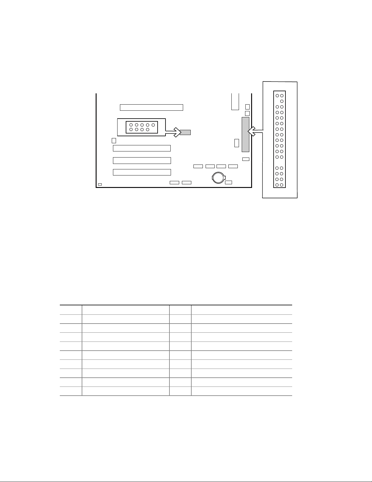
Connecting Internal Headers
Before connecting internal headers, observe the precautions in “Before You Begin” on page 39.
B
1 2
210
A
19
33 34
TP00194
A Front Panel USB 2.0 Header
B Front Panel Header
Figure 20. Location of Internal Headers
Connecting the Front Panel Header
Before connecting the front panel header, observe the precautions in “Before You Begin” on
page 39. Figure 20 (above) shows the location of the front panel header. Table 12 shows the pin
assignments for the front panel header.
Table 12. Front Panel Header (J7J1)
Pin Signal Name Pin(s) Function
1 Power LED Anode 2 5VSB
3 Key 4 Unused
5 GND 6 Unused
7 HDD Activity LED Anode 8 Unused
9 HDD Activity LED Cathode 10 Unused
11 Power Switch 12 NIC#1 Activity LED Anode
13 GND (Power Switch) 14 NIC#1 Activity LED Cathode
15 FP_RST* 16 I1C SDA
17 GND (Reset Switch) 18 I2C SDA
continued
Server Board Installation and Upgrades 55
Page 56

Table 12. Front Panel Header (J7J1) (continued)
19 ACPI Sleep Switch 20 Chassis Intrusion
21 GND (ACPI Sleep Switch 22 NIC#2 Activity LED Anode
23 Unused 24 NIC#2 Activity LED Cathode
25 Key 26 Key
27 Unused 28 Unused
29 Unused 30 Unused
31 Unused 32 Unused
33 Unused 34 Unused
Connecting the USB 2.0 Header
Before connecting the USB 2.0 header, observe the precautions in “Before You Begin” on page 39.
Figure 20 shows the location of the USB 2.0 header. Table 13 shows the pin assignments for the
front panel header.
Table 13. USB 2.0 Header (J7E1)
Pin Signal name Pin Signal name
1 USB_FNT1_PWR 2 USB_FNT1_PWR
3 USB_FRONT1_L* 4 USB_FRONT2_L*
5 USB_ FRONT1_L 6 USB_FRONT2_L
7 Ground 8 Ground
9 Key 10 USB_ OC_FNT_R1
Note: USB ports may be assigned as needed.
56 Intel Server Board S875WP1-E Product Guide
Page 57

Connecting Hardware Control and Power Cables
Figure 21 shows the location of the hardware control (fans and chassis intrusion) headers and
power supply connectors.
J1B1
J7B1
A. System Fan 4 Header
B. CPU Fan
C. Main Power Connector
D. Auxiliary Power Connector
E. System Fan 1 Header
Figure 21. Location of the Fan Headers and Power Connectors
12 V
H
I
J9A1
A B C
J1F1
G
F. System Fan 2 Header
G. Chassis Intrusion Header
H. System Fan 3 Header
I. +12V CPU Power Connector
D
E
J6J3
F
J6J2
TP00195
Server Board Installation and Upgrades 57
Page 58
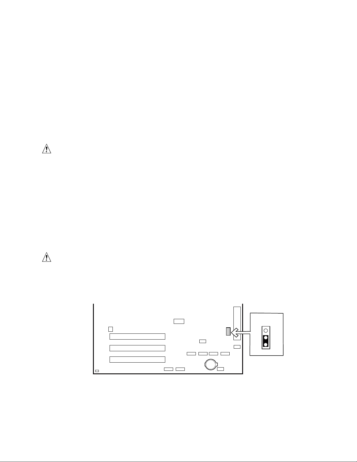
Connecting Fans
Connect the processor’s fan heatsink cable to the processor fan header on the board. Connect the
chassis fan cables to the board fan headers. See Figure 21 for fan header locations.
Chassis Intrusion
Connect the chassis intrusion cable from the chassis to the 1 x 2 header on the board.
Connecting Power Cables
CAUTION
Failure to use an ATX12V power supply, or not connecting the 12 V
processor core voltage power supply connector to the desktop board may
+result in damage to the desktop board and/or power supply.
Figure 21 shows the location of power connectors.
1. Observe the precautions in “Before You Begin” on page 39.
2. Connect the 12 V processor core voltage power supply cable to the 2x2 connector.
3. Connect the main power cable to the 2x10 connector.
Setting the BIOS Configuration Jumper
CAUTION
Always turn off the power and unplug the power cord from the server before
changing the jumper. Moving the jumper with the power on may result in
unreliable server operation.
J8J2
3
2
1
TP00196
Figure 22. BIOS Configuration Jumper Block Location
58 Intel Server Board S875WP1-E Product Guide
Page 59
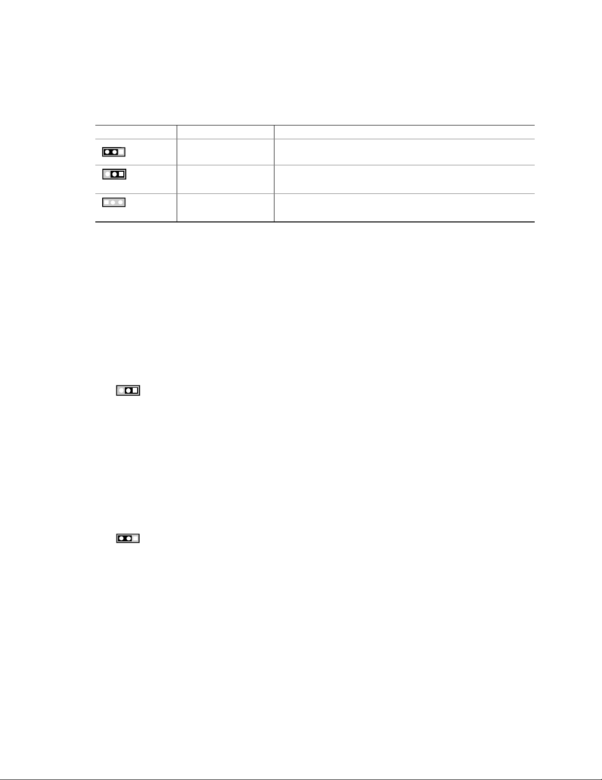
This three-pin jumper block, shown in Figure 22, enables all server board configurations to be done
in BIOS Setup. Table 14 shows the jumper settings for the Setup program modes.
Table 14. Jumper Settings for the BIOS Setup Program Modes (J8J2)
Jumper Setting Mode Description
1
3
1
3
Normal (default) (1-2) The BIOS uses the current configuration and passwords for
booting.
Configure (2-3) After the Power-On Self-Test (POST) runs, the BIOS displays
the Maintenance Menu. Use this menu to clear passwords.
1
3
Recovery (None) The BIOS recovers data from a recovery diskette in the event of
a failed BIOS update.
Clearing Passwords
This procedure assumes that the board is installed in the computer and the configuration jumper
block is set to normal mode.
1. Observe the precautions in “Before You Begin” on page 39.
2. Turn off all peripheral devices connected to the computer. Turn off the computer. Disconnect
the computer’s power cord from the AC power source (wall outlet or power adapter).
3. Remove the computer cover.
4. Find the configuration jumper block (see (figure to be indicated)).
5. Place the jumper on pins 2-3 as shown below.
1
3
6. Replace the cover, plug in the computer, turn on the computer, and allow it to boot.
7. The computer starts the Setup program. Setup displays the Maintenance menu.
8. Use the arrow keys to select Clear Passwords. Press <Enter> and Setup displays a pop-up
screen requesting that you confirm clearing the password. Select Yes and press <Enter>.
Setup displays the maintenance menu again.
9. Press <F10> to save the current values and exit Setup.
10. Turn off the computer. Disconnect the computer’s power cord from the AC power source.
11. Remove the computer cover.
12. To restore normal operation, place the jumper on pins 1-2 as shown below.
1
3
Replace the cover, plug in the computer, and turn on the computer.
Server Board Installation and Upgrades 59
Page 60

Replacing the Battery
When your server is turned off, a lithium battery maintains the time-of-day clock and the keeps the
values in CMOS RAM. The location of the server board battery is shown in Figure 23 on page 62.
The battery should last about seven years whereupon it begins to lose voltage. When the voltage
drops below a certain level, the BIOS Setup program settings stored in CMOS RAM (for example,
the date and time) might not be accurate. Replace the battery with an equivalent one.
CAUTION
Refer to technically qualified persons only for replacement of battery.
CAUTION
Risk of explosion if the battery is replaced with an incorrect type. Batteries
should be recycled where possible. Disposal of used batteries must be in
accordance with local environmental regulations.
PRECAUTION
Risque d'explosion si la pile usagée est remplacée par une pile de type
incorrect. Les piles usagées doivent être recyclées dans la mesure du
possible. La mise au rebut des piles usagées doit respecter les
réglementations locales en vigueur en matière de protection de
l'environnement.
(French)
FORHOLDSREGEL
Eksplosionsfare, hvis batteriet erstattes med et batteri af en forkert type.
Batterier bør om muligt genbruges. Bortskaffelse af brugte batterier bør
foregå i overensstemmelse med gældende miljølovgivning.
(Danish)
OBS!
Det kan oppstå eksplosjonsfare hvis batteriet skiftes ut med feil type.
Batterier bør sendes til gjenvinning hvis det er mulig. Brukte batterier bør
kastes i henhold til gjeldende miljølovgivning.
(Norwegian)
VIKTIGT!
Risk för explosion om batteriet ersätts med felaktig batterityp. Batterier bör
om möjligt återvinnas. Batterier ska kasseras enligt de lokala
miljövårdsbestämmelserna.
(Swedish)
60 Intel Server Board S875WP1-E Product Guide
Page 61

VARO
Räjähdysvaara, jos pariston tyyppi on väärä. Paristot on kierrätettävä, jos se
on mahdollista. Käytetyt paristot on hävitettävä paikallisten
ympäristömääräysten mukaisesti.
(Finnish)
VORSICHT
Bei falschem Einsetzen einer neuen Batterie besteht Explosionsgefahr. Die
Batterie darf nur durch denselben oder einen entsprechenden, vom Hersteller
empfohlenen Batterietyp ersetzt werden. Entsorgen Sie verbrauchte Batterien
den Anweisungen des Herstellers entsprechend.
(German)
AVVERTIMENTO
Esiste il pericolo di un esplosione se la pila non viene sostituita in modo
corretto. Utilizzare solo pile uguali o di tipo equivalente a quelle consigliate
dal produttore. Per disfarsi delle pile usate, seguire le istruzioni del
produttore.
(Italian)
PRECAUCIÓN
Existe peligro de explosión si la pila no se cambia de forma adecuada. Utilice
solamente pilas iguales o del mismo tipo que las recomendadas por el
fabricante del equipo. Para deshacerse de las pilas usadas, siga igualmente las
instrucciones del fabricante.
(Spanish)
WAARSCHUWING
Er bestaat ontploffingsgevaar als de batterij wordt vervangen door een
onjuist type batterij. Batterijen moeten zoveel mogelijk worden gerecycled.
Houd u bij het weggooien van gebruikte batterijen aan de plaatselijke
milieuwetgeving.
(Dutch)
ATENÇÃO
Haverá risco de explosão se a bateria for substituída por um tipo de bateria
incorreto. As baterias devem ser recicladas nos locais apropriados. A
eliminação de baterias usadas deve ser feita de acordo com as
regulamentações ambientais da região.
(Brazilian Portuguese)
Server Board Installation and Upgrades 61
Page 62

To replace the battery, follow these steps:
1. Observe the safety and ESD precautions at the beginning of this chapter.
2. Turn off all peripheral devices connected to the server. Disconnect the server’s power cord
from the AC power source (wall outlet or power adapter).
3. Remove the server cover.
4. Locate the battery on the board (see Figure 23).
5. With your fingertip or a flathead screwdriver, gently pull back the tab away from the battery.
Pull out the battery. Note the orientation of the “+”on the battery.
6. Install the new battery in the connector, orienting the “+” as shown in Figure 23.
7. Replace the server cover.
Figure 23. Removing the Battery
TP00197
62 Intel Server Board S875WP1-E Product Guide
Page 63

3 Configuration Software and Utilities
This chapter tells you how to update the BIOS by with the Intel Flash Memory Update Utility, and
how to recover the BIOS if an update fails.
Updating the BIOS with the Intel® Flash Memory Update Utility
With the Intel Flash Memory Update Utility you can update the system BIOS from a floppy disk or
other bootable media. The utility available from the Web provides a simple method for creating a
bootable flash memory update floppy that will automatically update your BIOS.
• Prepare for the update
• Update the BIOS
• Recover the BIOS if an update fails
Obtaining the BIOS Update File
You can update to a new version of the BIOS or change the language section of the BIOS by using
the BIOS update file. The BIOS update file is a compressed self-extracting archive that contains all
the files you need to update the BIOS. The BIOS update file contains:
• New BIOS files
• BIOS recovery files
• Intel Flash Memory Update Utility
You can obtain the BIOS update file through your server supplier or from the Intel World Wide
Web site:
http://support.intel.com/support/motherboards/server/
NOTE
✏
Review the instructions distributed with the update utility before attempting a
BIOS update.
Configuration Software and Utilities 63
Page 64

Recording the Current BIOS Settings
1. Boot the server and press <F2> when you see the message:
Press <F2> Key if you want to run SETUP
✏
NOTE
Do not skip step 2. You will need these settings to configure your server at
the end of the upgrade procedure.
2. Write down the current settings in the BIOS Setup program.
Creating Bootable Media
You can create bootable media with a:
• CD writer
• Normal diskette drive or an LS-120 diskette drive
Creating a Bootable CD
The instructions below assume a bootable diskette is used. When using a CD writer to use a CD,
follow the instructions provided with your CD writer to make a bootable CD using floppy
emulation and bootable files.
Creating a Bootable Diskette
✏
NOTE
If your drive A is an LS-120 diskette drive, you must use a 1.44 MB diskette
as the bootable BIOS update diskette. The server is unable to recover a
BIOS from an LS-120 diskette.
To create a bootable diskette using a DOS system:
• Place an unformatted diskette in the diskette drive and format the diskette using the /s option.
Example:
Alternatively, place a formatted diskette in the diskette drive and use the sys command.
•
Example:
format a: /s
sys a:
To create a bootable diskette using a non-DOS system:
1. Obtain the BIOS update file through your server supplier or from the Intel World Wide Web
site: http://support.intel.com/support/motherboards/server/
2. Copy the BIOS update file to a temporary directory on your hard disk.
3. Change to the temporary directory.
4. To extract the files, double click on the BIOS update file, for example, EABIOSxx.EXE.
5. One of the extracted files is MK_BOOTZ.EXE. Double click on this file to extract the
README.TXT file.
6. Follow the directions in the README.TXT file.
64 Intel Server Board S875WP1-E Product Guide
Page 65

Creating a BIOS Update Media
1. Obtain the BIOS update file through your server supplier or from the Intel World Wide
Web site:
http://support.intel.com/support/motherboards/server/
2. Copy the BIOS update file to a temporary directory on your hard disk.
3. From the C:\ prompt, change to the temporary directory.
4. To extract the file, type the name of the BIOS upgrade file, for example, EABIOSxx.
5. Press <Enter>. The extracted file contains the following files:
• LICENSE.TXT
• BIOINSTR.TXT
• BIOS.EXE
• MK_BOOTZ.EXE
6. Read the LICENSE.TXT file, which contains the software license agreement, and the
BIOINSTR.TXT file, which contains the instructions for the BIOS update.
7. Insert the bootable diskette into drive A.
8. Extract the BIOS.EXE file to the diskette. From the directory that contains the BIOS.EXE file
type:
BIOS A:
9. Press <Enter>.
10. The diskette now holds the new BIOS files, the Intel Flash Update Utility, and the
recovery files.
Configuration Software and Utilities 65
Page 66

Updating the BIOS
CAUTION
The AUTOEXEC.BAT file provided with the update files updates the BIOS
in two parts: first updating the boot block and displaying the
completed successfully
message and second, updating the BIOS core.
You will be asked to reboot the system when the update process is complete.
Do not interrupt the process or the system may not be capable of rebooting.
1. Boot the server with the bootable BIOS upgrade diskette in drive A. During system boot, the
AUTOEXEC.BAT file provided with the update files will automatically run the BIOS update
process.
The AUTOEXEC.BAT file updates the BIOS in two parts: first updating the boot block and
displaying the
Operation completed successfully message and then updating the BIOS
core.
2. When the update process is complete, the monitor will display a message telling you to remove
the diskette and to reboot the system.
3. As the server boots, check the BIOS identifier (version number) to make sure the upgrade was
successful. If a logo appears, press <Esc> to view the POST messages.
4. Enter BIOS Setup program by pressing <F2> when you see the message:
Press <F2> to Run SETUP
5. For proper operation, load the BIOS Setup program defaults. To load the defaults, press <F9>.
6. To accept the defaults, press <Enter>.
7. In Setup, enter the settings you wrote down before beginning the BIOS upgrade.
8. To save the settings, press <F10>.
9. To accept the settings, press <Enter>.
10. Turn off the server and reboot.
Operation
66 Intel Server Board S875WP1-E Product Guide
Page 67

Recovering the BIOS
It is unlikely that anything will interrupt the BIOS update, however, if an interruption occurs, the
BIOS could be damaged. The following steps explain how to recover the BIOS if an update fails.
The following procedure uses recovery mode for the Setup program. See page 58 for more
information on Setup modes.
NOTE
✏
Because of the small amount of code available in the boot block area, there is
no video support. You will not see anything on the screen during this
procedure. Monitor the procedure by listening to the speaker and looking at
the diskette drive LED.
1. Turn off the server, disconnect the server’s power cord, and disconnect all external peripherals.
2. Remove the server cover and locate the configuration jumper block (J8J2) (see Figure 22).
3. Remove the jumper from all pins as shown below to set recovery mode for Setup.
13
4. Insert the bootable BIOS update diskette into diskette drive A.
5. Replace the server cover, connect the power cord, turn on the server, and allow it to boot. The
recovery process will take a few minutes. Listen to the speaker and watch for drive A activity.
• Upon applying power, drive A will begin to show activity. In about a minute, two beeps are
heard and drive A activity ceases (temporarily) indicating the successful recovery of the
BIOS core. Drive A activity will begin again followed by two more beeps indicating the
successful recovery of the boot block. This sequence of events indicates that successful
BIOS recovery has taken place.
• A series of continuous beeps indicates that BIOS recovery has failed.
6. If recovery fails, return to step 1 and repeat the recovery process.
7. If recovery is successful, turn off the server, disconnect the power cord, and remove the server
cover.
8. On the jumper block (J8J2), reinstall the jumper back on pins 1-2 as shown below to set normal
mode for Setup.
13
9. Leave the update diskette in drive A, replace the server cover, and connect the server’s
power cord.
10. Turn on the server and continue with the BIOS update (see page 66).
Configuration Software and Utilities 67
Page 68

Using the Setup Program
You can use the BIOS Setup program to change the configuration information and boot sequence
for the server. This chapter tells you how to access the BIOS Setup program and lists Setup
features, options, and default settings.
NOTE
✏
For reference purposes, you should write down the current Setup settings.
BIOS Setup Program Modes
When you make changes to the settings, update this record.
The BIOS Setup program has three modes of operation:
• Normal mode for normal operations
• Configure mode for clearing passwords (see Chapter 2 for instructions)
• Recovery mode for BIOS recovery
The BIOS Setup Program Operating mode is controlled by the setting of the configuration jumper
block. The jumper is set to normal mode at the factory. The Maintenance menu is not available
when Setup is used with the jumper in normal mode. The Maintenance menu is available only when
the BIOS configuration jumper covers pins two and three.
The BIOS Setup program can be used to view and change the BIOS settings for the server. The
BIOS Setup program is accessed by pressing the <F2> key after the Power-On Self-Test (POST)
memory test begins and before the operating system boot begins. The menu bar is shown below.
Maintenance Main Advanced Security Power Boot Exit
Table 15. BIOS Setup Program Menu Bar
Maintenance Main Advanced Security Power Boot Exit
Clears
passwords and
Boot Integrity
Service (BIS)*
credentials. View
and change the
CPU frequency
ratio
View BIOS
versions,
processor
speed and
type,
memory and
memory
mode.
Set
language,
system date
and time.
Allocate
resources for
hardware
components
Configures
advanced
features
available
through the
chipset
Sets
passwords
and security
features
Configures
power
management
features
Selects boot
options and
power supply
controls
Saves or
discards
changes to
Setup
program
options
* For information about the BIS, refer to the Intel Web site at: http://developer.intel.com/design/security/index1.htm
68 Intel Server Board S875WP1-E Product Guide
Page 69

Table 16 shows the function keys available for menu screens.
Table 16. BIOS Setup Program Function Keys
BIOS Setup Program Function Key Description
<←> or <→>
<↑> or <↓>
<Tab> Moves cursor to the next field.
<Enter> Executes command or selects the submenu.
<F9> Load the default configuration values for the current menu.
<F10> Save the current values and exits the BIOS Setup program.
<Esc> Exits the menu.
Selects a different menu screen.
Moves cursor up or down.
Maintenance Menu
This menu is used to clear passwords and to access processor information. Setup only displays this
menu when the BIOS Configuration jumper is in the configure mode. See page 58 for information
about setting the configure mode. To access this menu, select Maintenance on the menu bar at the
top of the screen.
Maintenance
Main Advanced Security Power Boot Exit
Table 17. Maintenance Menu
Feature Options Description
CPU Frequency
Clear All Passwords
Clear BIS Credentials
CPU Stepping Signature No options Displays CPU’s Stepping Signature.
CPU Microcode Update
Revision
• 8 to 1 ratio (default)
• 12 to 1 ratio through
39 to 1 ratio
• Ok (default)
• Cancel
• Ok (default)
• Cancel
No options Displays CPU’s Microcode Update Revision.
Clears the user and administrative passwords.
Clears the Wired for Management Boot Integrity
Service (BIS) credentials.
Configuration Software and Utilities 69
Page 70

Main Menu
To access this menu, select Main on the menu bar at the top of the screen.
Maintenance
Table 18 describes the Main Menu. This menu reports processor and memory information and is for
configuring the system date and system time.
Table 18. Main Menu
Feature Options Description
BIOS Version No options Displays the version of the BIOS.
Processor Type No options Displays processor type.
Processor Speed No options Displays processor speed.
System Bus Speed No options Displays the system bus speed.
System Memory Speed No options Displays the memory speed.
Cache RAM No options Displays the size of second-level cache.
Total Memory No options Displays the total amount of RAM.
Memory Mode No options Displays whether interleaved or single-channel memory
DIMM Slot 1A
DIMM Slot 2A
DIMM Slot 1B
DIMM Slot 2B
Memory Configuration
Language
System Time
System Date
Main
Advanced Security Power Boot Exit
mode is in place.
No options Displays the amount and type of DIMMs in the memory
banks.
• Non-ECC
• ECC
• English (default)
• Español
• Hour, minute, and
second
• Day of week
Month/day/year
Allows the user to enable error reporting in the system and
all installed memory supported ECC. If non-ECC memory
is installed, BIOS will detect and change the setting to nonECC.
Selects the current default language used by the BIOS
(Deutsch, Italiano, and Français available via .lng files).
Set current time. Use the Tab key to navigate fields
Set current date. Use the Tab key to navigate fields.
NOTE
✏
Additional language support is available. For more information visit Intel’s support
web site at: www.support.intel.com/support/motherboards/server/S875WP1-E
70 Intel Server Board S875WP1-E Product Guide
Page 71

Advanced Menu
To access this menu, select Advanced on the menu bar at the top of the screen.
Maintenance Main
Table 19 describes the Advanced Menu. This menu is used for setting advanced features that are
available through the chipset.
Advanced
Security Power Boot Exit
PCI Configuration
Boot Configuration
Peripheral Configuration
Drive Configuration
Floppy Configuration
Event Log Configuration
Video Configuration
USB Configuration
Chipset Configuration
Fan Control Configuration
Hardware Monitoring
Remote Access Configuration
Table 19. Advanced Menu
Feature Options Description
PCI Configuration Select to display
submenu
Boot Configuration Select to display
submenu
Peripheral Configuration Select to display
submenu
Drive Configuration Select to display
submenu
Floppy Configuration Select to display
submenu
Event Log Configuration Select to display
submenu
Video Configuration Select to display
submenu
USB Configuration Select to display
submenu
Chipset Configuration Select to display
submenu
Fan Control Configuration Select to display
submenu
Hardware Monitoring Select to display
submenu
Remote Access Configuration Select to display
submenu
Displays the PCI Configuration submenu.
Displays the Boot Configuration submenu.
Displays the Peripheral Configuration submenu.
Displays the Drive Configuration submenu.
Displays the Floppy Configuration submenu.
Displays the Event Log Configuration submenu.
Displays the Video Configuration submenu
Displays the USB Configuration submenu
Displays the Chipset Configuration submenu
Displays the Fan Control Configuration submenu
Displays the Hardware Monitoring submenu.
Displays the Remote Access Configuration submenu.
Configuration Software and Utilities 71
Page 72
PCI Configuration Submenu
To access this submenu, select Advanced on the menu bar, then PCI Configuration.
Maintenance Main
Boot Configuration
Peripheral Configuration
Drive Configuration
Floppy Configuration
Event Log Configuration
Video Configuration
USB Configuration
Chipset Configuration
Fan Control Configuration
Hardware Monitoring
Remote Access Configuration
The submenu represented by Table 20 is for configuring the IRQ priority of PCI slots individually.
Advanced
Security Power Boot Exit
PCI Configuration
Table 20. PCI Configuration Submenu
Feature Options Description
PCI Slot 1 IRQ Priority
PCI Slot 2 IRQ Priority
(Note 1)
PCI Slot 3 IRQ Priority
(Note 1)
Notes:
1. Additional interrupts may be available if certain on-board devices (such as the serial and parallel ports) are disabled.
• Auto (default)
• 5
• 9
• 10
• 11
• Auto (default)
• 5
• 9
• 10
• 11
• Auto (default)
• 5
• 9
• 10
• 11
Allows selection of IRQ priority.
Allows selection of IRQ priority.
Allows selection of IRQ priority.
72 Intel Server Board S875WP1-E Product Guide
Page 73

Boot Configuration Submenu
To access this submenu, select Advanced on the menu bar, then Boot Configuration.
Maintenance Main
PCI Configuration
Peripheral Configuration
Drive Configuration
Floppy Configuration
Event Log Configuration
Video Configuration
USB Configuration
Chipset Configuration
Fan Control Configuration
Hardware Monitoring
Remote Access Configuration
Advanced
Security Power Boot Exit
Boot Configuration
The submenu represented by Table 21 is for setting Plug and Play (PnP) options, resetting
configuration data, and the power-on state of the Numlock key.
Table 21. Boot Configuration Submenu
Feature Options Description
Plug and Play O/S
Numlock
• No (default)
• Yes
• Off
• On (default)
Specifies if manual configuration is desired.
No lets the BIOS configure all devices. This setting is
appropriate when using a Plug and Play operating system.
Yes lets the operating system configure Plug and Play
devices not required to boot the system. This option is
available for use during lab testing.
Specifies the power-on state of the Numlock feature on the
numeric keypad of the keyboard.
Configuration Software and Utilities 73
Page 74

Peripheral Configuration Submenu
To access this submenu, select Advanced on the menu bar, then Peripheral Configuration.
Maintenance Main
PCI Configuration
Boot Configuration
Drive Configuration
Floppy Configuration
Event Log Configuration
Video Configuration
USB Configuration
Chipset Configuration
Fan Control Configuration
Hardware Monitoring
Remote Access Configuration
The submenu represented in Table 22 is used for configuring server peripherals.
Advanced
Security Power Boot Exit
Peripheral Configuration
Table 22. Peripheral Configuration Submenu
Feature Options Description
Serial Port A
Base I/O Address
Interrupt
Serial Port B
Mode
Base I/O address
Interrupt
• Disabled
• Enabled
• Auto (default)
• 3F8 (default)
• 2F8
• 3E8
• 2E8
• IRQ 3
• IRQ 4 (default)
• Disabled
• Enabled
• Auto (default)
• Normal
• IrDA SIR-A
• ASK_IR
• 3F8
• 2F8 (default)
• 3E8
• 2E8
• IRQ 3 (default)
• IRQ 4
Configures serial port A.
Auto assigns the first free COM port, normally COM1, the address
3F8h, and the interrupt IRQ4.
An * (asterisk) displayed next to an address indicates a conflict
with another device.
This option is available only when Serial Port A is set to Enabled.
Specifies the base I/O address for serial port A.
This option is available only when Serial Port A is set to Enabled.
Specifies the interrupt for serial port A.
Configures serial port B.
Auto assigns the first free COM port, normally COM 2, the address
3F8h, and the interrupt IRQ4.
An * (asterisk) displayed next to an address indicates a conflict
with another device.
This option is available to set Serial Port B Mode. This includes
Normal and Infared Modes.
This option is displayed only if Serial Port B is set to Enabled.
Specifies the base I/O address for serial port B.
This option is displayed only if Serial Port B is set to Enabled
Specifies the interrupt for serial port B.
continued
74 Intel Server Board S875WP1-E Product Guide
Page 75

Table 22. Peripheral Configuration Submenu (continued)
Feature Options Description
Parallel Port
Mode
Base I/O Address
Interrupt
DMA
10/100 NIC
Gigabit NIC
ATI Rage XL Video
Promise PDC20319
S150 TX4
• Disabled
• Enabled
• Auto (default)
• Output Only
• Bi-directional
(default)
• EPP
• ECP
• 378 (default)
• 278
• IRQ 5
• IRQ 7 (default)
• 1
• 3 (default)
• Disabled
• Enabled
(default)
• Disabled
• Enabled
(default)
• Disabled
• Enabled
(default)
• Disabled
• Enabled
(default)
Configures the parallel port.
Auto assigns LPT1 the address 378h and the
interrupt IRQ7.
An * (asterisk) displayed next to an address indicates a
conflict with another device.
Selects the mode for the parallel port. Not available if the
parallel port is disabled.
Output Only operates in AT-compatible mode.
Bi-directional operates in PS/2-compatible mode.
EPP is Extended Parallel Port mode, a high-speed
bi-directional mode.
ECP is Enhanced Capabilities Port mode, a high-speed
bi-directional mode.
This feature is present only when Parallel Port is set to
Enabled
Specifies the base I/O address for the parallel port.
This feature is present only when Parallel Port is set to
Enabled
Specifies the interrupt for the parallel port.
This feature is present only when Parallel Port Mode is set
to ECP
Specifies the DMA channel.
Enables or disables the on-board LAN#1 device.
Enables or disables the on-board LAN#2 device.
Enables or disables the on-board ATI* Rage XL video
controller.
Enables or disables RAID support.
Configuration Software and Utilities 75
Page 76

Drive Configuration Submenu
To access this submenu, select Advanced on the menu bar, then Drive Configuration.
Maintenance Main
PCI Configuration
Boot Configuration
Peripheral Configuration
Floppy Configuration
Event Log Configuration
Video Configuration
USB Configuration
Chipset Configuration
Fan Control Configuration
Hardware Monitoring
Remote Access Configuration
Advanced
Security Power Boot Exit
Drive Configuration
The menu represented in Table 23 is used to configure drive options.
Table 23. Drive Configuration Submenu
Feature Options Description
ATA / IDE
Configuration
Legacy IDE Channels
PCI IDE Bus Master
• Disabled
• Legacy
• Enhanced (default)
• PATA Pri Only
• PATA Sec Only
• PATA Pri and Sec
(default)
• P0 / P1 Only
• SATA P0 / P1, PATA
Sec
• SATA P0 / P1, PATA
Pri
• Enabled (default)
• Disabled
Selects the mode for the integrated IDE controller. When
Legacy is selected, a maximum of 4 drives can be
installed. When Enhanced is selected, a maximum of 6
drives can be installed.
This option is available only when Legacy is selected as
the IDE Mode.
continued
76 Intel Server Board S875WP1-E Product Guide
Page 77

Table 23. Drive Configuration Submenu (continued)
Hard Disk Pre-Delay
Intel (R) RAID
Technology
SATA Port -0 Select to display sub-
SATA Port -1 Select to display
PATA Primary Master Select to display
PATA Primary Slave Select to display
PATA Secondary
Master
PATA Secondary
Slave
• Disabled (default)
• 3 Seconds
• 6 Seconds
• 9 Seconds
• 12 Seconds
• 15 Seconds
• 21 Seconds
• 30 Seconds
• Disabled (default)
• Enabled
menu
sub-menu
sub-menu
sub-menu
Select to display
sub-menu
Select to display
sub-menu
Specifies the hard disk drive pre-delay.
Reports type of connected SATA device. When selected,
displays SATA Port-0 submenu.
Reports type of connected SATA device. When selected,
displays SATA Port-1 submenu.
Reports type of connected IDE device. When selected,
displays the Primary IDE Master submenu.
Reports type of connected IDE device. When selected,
displays the Primary IDE Slave submenu.
Reports type of connected IDE device. When selected,
displays the Secondary IDE Master submenu.
Reports type of connected IDE device. When selected,
displays the Secondary IDE Slave submenu.
Configuration Software and Utilities 77
Page 78

Primary/Secondary/SATA-0/SATA-1 Master/Slave Submenus
To access these submenus, select Advanced on the menu bar, then Drive Configuration, and then
the master or slave to be configured.
Maintenance Main
PCI Configuration
Boot Configuration
Peripheral Configuration
Floppy Configuration
Event Log Configuration
Video Configuration
USB Configuration
Chipset Configuration
Fan Control Configuration
Hardware Monitoring
Remote Access Configuration
Advanced
Security Power Boot Exit
Drive Configuration
There are four IDE submenus: primary master, primary slave, secondary master, and secondary
slave. Table 24 shows the format of the IDE submenus. For brevity, only one example is shown.
Table 24. Primary/Secondary/SATA-0/SATA-1 Master/Slave Submenus
Feature Options Description
Drive Installed No options Displays the type of drive installed.
Type
Maximum Capacity No options Displays the capacity of the drive. (SATA only)
LBA / Large Mode
Block Mode
PIO Mode
DMA Mode
• User
• Auto (default)
• Disabled
• Auto (default)
• Disabled
• Auto (default)
• Auto (default)
• 0
• 1
• 2
• 3
• 4
• Auto (default)
• SWDMA 0, 1, or 2
• MWDMA 0, 1, or 2
• UDMA 0, 1, 2, 3, 4, 5
Specifies the drive configuration.
User allows capabilities to be changed.
Auto fills-in capabilities from the device.
This option can be changed only if User is selected as
the type.
This option can be changed only if User is selected as
the type.
This option can be changed only if User is selected as
the type.
This option can be changed only if User is selected as
the type.
SWDMA = Single Word DMA
MWDMA = Multi Word DMA
UDMA = Ultra DMA
continued
78 Intel Server Board S875WP1-E Product Guide
Page 79

Table 24. Primary/Secondary/SATA-0/SATA-1 Master/Slave Submenus (continued)
Feature Options Description
S.M.A.R.T
Cable Detected
Note: These configuration options appear only if an IDE device is installed.
(Note)
• Auto (default)
• Disabled
• Enabled
No options Displays the type of cable connected to the IDE
This option can be changed only if User is selected as
the type. If Auto is selected, this option is not displayed.
Enables or disables Self-monitoring, Analysis, and
Reporting Technology.
interface: 40-conductor or 80-conductor
(for ATA-66/100 devices).
Floppy Configuration Submenu
To access this menu, select Advanced on the menu bar, then Floppy Configuration.
Maintenance Main
PCI Configuration
Boot Configuration
Peripheral Configuration
Drive Configuration
Event Log Configuration
Video Configuration
USB Configuration
Chipset Configuration
Fan Control Configuration
Hardware Monitoring
Remote Access Configuration
Advanced
Security Power Boot Exit
Floppy Configuration
The submenu represented by Table 25 is used for configuring the diskette drive.
Table 25. Floppy Configuration Submenu
Feature Options Description
Diskette Controller
Floppy A
Diskette Write-Protect
• Disabled
• Enabled (default)
• Disabled
• 360 KB 5¼ inch
• 1.2 MB 5¼ inch
• 720 KB 3½ inch
• 1.44 MB 3½ inch (default)
• 2.88 MB 3½ inch
• Disabled (default)
• Enabled
Disables or enables the integrated diskette
controller.
Specifies the capacity and physical size of
diskette drive A.
Disables or enables write-protect for the
diskette drive.
Configuration Software and Utilities 79
Page 80

Event Log Configuration Submenu
To access this menu, select Advanced on the menu bar, then Event Log Configuration.
Maintenance Main
PCI Configuration
Boot Configuration
Peripheral Configuration
Drive Configuration
Floppy Configuration
Video Configuration
USB Configuration
Chipset Configuration
Fan Control Configuration
Hardware Monitoring
Remote Access Configuration
Advanced
Security Power Boot Exit
Event Log Configuration
The submenu represented by Table 26 is used to configure the event logging features.
Table 26. Event Log Configuration Submenu
Feature Options Description
Event Log No options Indicates if there is space available in the event log.
View Event Log [Enter] Displays the event log.
Clear Event Log
Event Logging
ECC Event Logging
Mark Events As Read
• OK (default)
• Cancel
• Disabled
• Enabled (default)
• Disabled
• Enabled (default)
• OK (default)
• Cancel
Clears the event log after rebooting.
Enables logging of events.
Enables logging of ECC events.
Marks all events as read.
80 Intel Server Board S875WP1-E Product Guide
Page 81
Video Configuration Submenu
To access this menu, select Advanced on the menu bar, then Video Configuration.
Maintenance Main
PCI Configuration
Boot Configuration
Peripheral Configuration
Drive Configuration
Floppy Configuration
Event Log Configuration
USB Configuration
Chipset Configuration
Fan Control Configuration
Hardware Monitoring
Remote Access Configuration
Advanced
Security Power Boot Exit
Video Configuration
The submenu represented by Table 27 is used to configure the video features.
Table 27. Video Configuration Submenu
Feature Options Description
AGP Aperture Size
Primary Video Adapter
• 4MB
• 8MB
• 16MB
• 32MB
• 64MB (default)
• 128MB
• 256MB
• AGP (default)
• PCI
Sets the aperture size for the AGP video controller.
Allows selecting an AGP or PCI video controller as
the display device that will be active when the system
boots.
Configuration Software and Utilities 81
Page 82

USB Configuration Submenu
To access this menu, select Advanced on the menu bar, then USB Configuration.
Maintenance Main
PCI Configuration
Boot Configuration
Peripheral Configuration
Drive Configuration
Floppy Configuration
Event Log Configuration
Video Configuration
Chipset Configuration
Fan Control Configuration
Hardware Monitoring
Remote Access Configuration
Advanced
Security Power Boot Exit
USB Configuration
The submenu represented by Table 28 is used to configure the USB features.
Table 28. USB Configuration Submenu
Feature Options Description
High-Speed USB
Legacy USB support
USB 2.0 Legacy Support
USB Data Area
Relocation
• Enabled (default)
• Disabled
• Disabled
• Enabled (default)
• FullSpeed (default)
• HiSpeed
• Disabled (default)
• Enabled
Enables or disables the USB 2.0 driver. Disable this
option if the driver is not available.
Allows the use of legacy USB accessories.
FullSpeed = 480 Mbps
HiSpeed = 12 Mbps
82 Intel Server Board S875WP1-E Product Guide
Page 83

Chipset Configuration Submenu
To access this menu, select Advanced on the menu bar, then Chipset Configuration.
Maintenance Main
PCI Configuration
Boot Configuration
Peripheral Configuration
Drive Configuration
Floppy Configuration
Event Log Configuration
Video Configuration
USB Configuration
Fan Control Configuration
Hardware Monitoring
Remote Access Configuration
Advanced
Security Power Boot Exit
Chipset Configuration
The submenu represented by Table 29 is used to configure the chipset features.
Table 29. Chipset Configuration Submenu
Feature Options Description
ISA Enable Bit
PCI Latency Timer
• Disabled
• Enabled (default)
• 32
• 64
• 96
• 128
• 160
• 192
• 224
• 248
This option is required by some IDE expansion
devices.
continued
Configuration Software and Utilities 83
Page 84

Table 29. Chipset Configuration Submenu (continued)
Extended Configuration
SDRAM Frequency
SDRAM Timing Control
CPC Override
SDRAM RAS Act. To Pre. No options
SDRAM CAS# Latency No options
SDRAM RAS# to CAS delay No options
SDRAM RAS# Precharge No options
• Default (default)
• User Defined
• Auto (default)
• 266
• 333
• 400
• Auto (default)
• Manual –
Aggressive
• Manual – User
Defined
• Auto (default)
• Enable
• Disable
This option is available only if User Defined is
selected as the Extended Configuration option. It
allows the user to override the detected memory
frequency value.
This option is available only if User Defined is
selected as the Extended Configuration option.
Auto: Timings are programmed according to the
memory detected.
Manual – Aggressive: Selects the most aggressive
user-defined timings.
Manual – User Defined: Allows manual override of
detected SDRAM settings.
Command Per Clock. When enabled, it allows the
DRAM controller to attempt chip select assertions in
two consecutive common clocks.
84 Intel Server Board S875WP1-E Product Guide
Page 85

Fan Control Configuration Submenu
To access this menu, select Advanced on the menu bar, then Fan Control Configuration.
Maintenance Main
PCI Configuration
Boot Configuration
Peripheral Configuration
Drive Configuration
Floppy Configuration
Event Log Configuration
Video Configuration
USB Configuration
Chipset Configuration
Hardware Monitoring
Remote Access Configuration
Advanced
Security Power Boot Exit
Fan Control Configuration
The submenu represented by Table 30 is used to configure the fan control features.
Table 30. Fan Control Configuration Submenu
Feature Options Description
Fan Control
Lowest Fan Speed
• Disabled
• Enabled (default)
• Slow (default)
• Off
This option is available only if Enabled is selected as
the Fan Control.
Slow: At low system temperatures, the fans will
continue to run at a slow speed.
Off: At low system temperatures, the fans will turn off.
Configuration Software and Utilities 85
Page 86

Hardware Monitoring Submenu
To access this menu, select Advanced on the menu bar, then Hardware Monitoring.
Maintenance Main
PCI Configuration
Boot Configuration
Peripheral Configuration
Drive Configuration
Floppy Configuration
Event Log Configuration
Video Configuration
USB Configuration
Chipset Configuration
Fan Control Configuration
Remote Access Configuration
Advanced
Security Power Boot Exit
Hardware Monitoring
The submenu represented by Table 30 is used to view the hardware that is monitored. These
options can be viewed only, not changed.
Table 31. Hardware Monitoring Submenu
Feature Options Description
Processor Zone
Temperature
System Zone 1
Temperature
System Zone 2
Temperature
Processor Fan Speed No options Displays the speed at which the processor fan is
VReg Fan Speed No options Displays the speed for the rear fan.
Front Fan Speed No options Displays the speed for the front fan.
+1.5Vin No options Displays voltage level.
Vccp No options Displays voltage level.
+3.3Vin No options Displays voltage level.
+5Vin No options Displays voltage level.
+12Vin No options Displays voltage level.
No options Displays processor zone temperature.
No options Displays system zone 1 temperature.
No options Displays system zone 2 temperature.
running.
86 Intel Server Board S875WP1-E Product Guide
Page 87

Remote Access Configuration Submenu
To access this menu, select Advanced on the menu bar, then Remote Access Configuration.
Maintenance Main
PCI Configuration
Boot Configuration
Peripheral Configuration
Drive Configuration
Floppy Configuration
Event Log Configuration
Video Configuration
USB Configuration
Chipset Configuration
Fan Control Configuration
Hardware Monitoring
Advanced
Security Power Boot Exit
Remote Access Configuration
The submenu represented by Table 32 is used to configure the remote access features.
Table 32. Remote Access Configuration Submenu
Feature Options Description
Remote Access
Serial Port Number
Serial Port Mode
Terminal Type
Post Boot Support
• Disabled (default)
• Enabled
• COM1 (default)
• COM2
• 115200 8,n,1
• 57600 8,n,1 (default)
• 19200 8,n,1
• VT100
• Disabled (default)
• Enabled
Permits or denies the ability to remotely manage the
system.
This option is available only if Enabled is set for the
Remote Access option.
Specifies the serial port to use for console redirection.
In addition to selecting the port number in BIOS
setup, make sure the selected port is enabled for use.
This option is available only if Enabled is set for the
Remote Access option.
Specifies the modem parameters for the selected
Com port.
This option is available only if Enabled is set for the
Remote Access option.
This option is available only if Enabled is set for the
Remote Access option.
Specifies whether redirection should remain active
after booting to DOS. When enabled, redirection
remains active. When disabled, redirection is disabled
upon booting to DOS.
Configuration Software and Utilities 87
Page 88

Security Menu
To access this menu, select Security from the menu bar at the top of the screen.
Maintenance Main Advanced
The menu represented by Table 33 is for setting passwords and security features.
Table 33. Security Menu
If no password entered previously:
Feature Options Description
Supervisor Password Is No options Reports if there is a supervisor password set.
User Password Is No options Reports if there is a user password set.
Set Supervisor Password Password can be up to seven
alphanumeric characters.
Set User Password Password can be up to seven
alphanumeric characters.
Clear User Password
User Access Level
Chassis Intrusion
Notes:
1. This feature appears only if a user password has been set.
2. This feature appears only if both a user password and a supervisor password have been set.
(Note 1)
(Note 2)
• Ok (default)
• No
• No Access
• View Only
• Limited
• Full (default)
• Disabled (default)
• Log
• Log, notify once
• Log, notify till cleared
Security
Power Boot Exit
Specifies the supervisor password.
Specifies the user password.
Clears the user password.
Sets BIOS Setup Utility access rights for user
level.
No Access: User cannot access BIOS Setup.
View Only: User can view BIOS Setup, but
cannot make any changes.
Limited: User can make limited changes in
BIOS Setup.
Full: User can change any field in BIOS Setup,
except for the Supervisor Password.
Determines whether the chassis will be
monitored for intrusions and how intrusion
logging should be handled.
88 Intel Server Board S875WP1-E Product Guide
Page 89
Power Menu
To access this menu, select Power from the menu bar at the top of the screen.
Maintenance Main Advanced Security
ACPI
The menu represented in Table 34 is for setting the power management features.
Table 34. Power Menu
Feature Options Description
ACPI No Options When selected, displays the ACPI submenu.
After Power Failure
Wake on PCI PME
• Stays Off
• Last State (default)
• Power On
• Stay Off (default)
• Power On
Specifies the mode of operation if an AC power loss occurs.
Power On restores power to the server.
Stay Off keeps the power off until the power button is
pressed.
Last State restores the previous power state before power
loss occurred.
Specifies how the computer responds to a PCI power
management event.
Power
Boot Exit
ACPI Submenu
To access this menu, select Power on the menu bar, then ACPI.
Maintenance Main Advanced Security
The submenu represented in Table 35 is for setting the ACPI features.
Table 35. ACPI Submenu
Feature Options Description
ACPI Suspend State
Wake on LAN from S5
• S1 State
• S3 State (default)
• Stay Off (default)
• Power On
Specifies the ACPI sleep state.
In ACPI soft-off mode only, determines how the system
responds to a LAN wake-up event.
Power
ACPI
Boot Exit
Configuration Software and Utilities 89
Page 90

Boot Menu
To access this menu, select Boot from the menu bar at the top of the screen.
Maintenance Main Advanced Security Power
The menu represented in Table 36 is used to set the boot features and the boot sequence.
Table 36. Boot Menu
Feature Options Description
Silent Boot
AddOn ROM Display
Mode
Intel® Rapid BIOS Boot
Scan User Flash Area
PXE Boot to LAN
USB Boot
Boot Device Priority Select to display
Removable Devices Select to display
ATAPI CD-ROM Drives Select to display
• Disabled (default)
• Enabled
• Enabled (default)
• Disabled
• Disabled
• Enabled (default)
• Disabled
• Enabled (default)
• Disabled (default)
• Enabled
• Disabled
• Enabled (default)
submenu
submenu
submenu
Disabled displays normal POST messages.
Enabled displays OEM graphic instead of POST
messages.
Enables the computer to boot without running certain
POST tests.
Enables the BIOS to scan the flash memory for user binary
files that are executed at boot time.
Enables PXE boot.
Enables the computer to boot from USB boot devices.
Specifies the boot sequence from the available types of
boot devices.
Specifies the boot sequence from the available removable
devices.
Specifies the boot sequence from the available ATAPI
CD-ROM drives.
Boot
Exit
90 Intel Server Board S875WP1-E Product Guide
Page 91
Boot Device Priority Submenu
To access this menu, select Boot on the menu bar, then Boot Devices Priority.
Maintenance Main Advanced Security Power Boot Exit
Boot Device Priority
Hard Disk Drives
Removable Devices
The submenu represented in Table 37 is for setting boot devices priority.
Table 37. Boot Device Priority Submenu
Feature Options Description
1st Boot Device
nd
2
Boot Device
rd
3
Boot Device
th
4
Boot Device
(Note 1)
• Removable Dev.
• Hard Drive
• ATAPI CD-ROM
®
• Intel
• Disabled
UNDI, PXE
Specifies the boot sequence from the available types of
boot devices. To specify boot sequence:
1. Select the boot device with <↑> or <↓>.
2. Press <Enter> to set the selection as the intended
boot device.
The default settings for the first through fourth boot
devices are, respectively:
• Removable Dev.
• Hard Drive
• ATAPI CD-ROM
• Intel UNDI, PXE-2.0
ATAPI CDROM Drives
Hard Disk Drives Submenu
To access this menu, select Boot on the menu bar, then Hard Disk Drives.
Maintenance Main Advanced Security Power Boot Exit
Boot Device Priority
Hard Disk Drives
Removable Devices
The submenu represented in Table 38 is for setting hard disk drive priority.
Table 38. Hard Disk Drives Submenu
Feature Options Description
1st Hard Disk Drive
Note: This boot device submenu appears only if at least one boot device of this type is installed. This list will display up
to twelve hard disk drives, the maximum number of hard disk drives supported by the BIOS.
(Note)
Dependent on installed
hard drives
Specifies the boot sequence from the available hard
disk drives. To specify boot sequence:
1. Select the boot device with <↑> or <↓>.
2. Press <Enter> to set the selection as the intended
boot device.
ATAPI CDROM Drives
Configuration Software and Utilities 91
Page 92

Removable Devices Submenu
To access this menu, select Boot on the menu bar, then Removable Devices.
Maintenance Main Advanced Security Power Boot Exit
Boot Device Priority
Hard Disk Drives
Removable Devices
The submenu represented in Table 39 is for setting removable device priority.
Table 39. Removable Devices Submenu
Feature Options Description
1st Removable Device
(Note)
Note: This boot device submenu appears only if at least one boot device of this type is installed. This list will display up
to four removable devices, the maximum number of removable devices supported by the BIOS.
Dependent on installed
removable devices
Specifies the boot sequence from the available
removable devices. To specify boot sequence:
1. Select the boot device with <↑> or <↓>.
2. Press <Enter> to set the selection as the intended
boot device.
ATAPI CDROM Drives
ATAPI CDROM Drives Submenu
To access this menu, select Boot on the menu bar, then ATAPI CDROM Drives.
Maintenance Main Advanced Security Power Boot Exit
Boot Device Priority
Hard Disk Drives
Removable Devices
The submenu represented in Table 40 is for setting ATAPI CDROM drive priority.
Table 40. ATAPI CDROM Drives Submenu
Feature Options Description
1st ATAPI CDROM Drive
(Note)
Note: This boot device submenu appears only if at least one boot device of this type is installed. This list will display up to
four ATAPI CDROM drives, the maximum number of ATAPI CDROM drives supported by the BIOS.
Dependent on installed
ATAPI CDROM drives
Specifies the boot sequence from the available
ATAPI CDROM drives. To specify boot sequence:
1. Select the boot device with <↑> or <↓>.
2. Press <Enter> to set the selection as the intended
boot device.
ATAPI CDROM Drives
92 Intel Server Board S875WP1-E Product Guide
Page 93

Exit Menu
To access this menu, select Exit from the menu bar at the top of the screen.
Maintenance Main Advanced Security Power Boot
The menu represented in Table 41 is for exiting the BIOS Setup program, saving changes, and
loading and saving defaults.
Table 41. Exit Menu
Feature Description
Exit Saving Changes Exits and saves the changes in CMOS SRAM.
Exit Discarding Changes Exits without saving any changes made in the BIOS Setup program.
Load Setup Defaults Loads the factory default values for all the Setup options.
Load Custom Defaults Loads the custom defaults for Setup options.
Save Custom Defaults Saves the current values as custom defaults. Normally, the BIOS reads the Setup
values from flash memory. If this memory is corrupted, the BIOS reads the
custom defaults. If no custom defaults are set, the BIOS reads the factory
defaults.
Discard Changes Discards changes without exiting Setup. The option values present when the
server was turned on are used.
Exit
Configuration Software and Utilities 93
Page 94

Page 95

4 Solving BIOS Problems
The board reports POST errors in two ways:
• By sounding a beep code
• By displaying an error message on the monitor
BIOS Beep Codes
The BIOS beep codes are listed in Table 42. The BIOS also issues a beep code (one long tone
followed by two short tones) during POST if the video configuration fails, or if an external
ROM module does not properly checksum to zero.
Table 42. Beep Codes
Number of Beeps Description
1 Refresh failure
2 Parity cannot be reset
3 First 64 Kb memory failure
4 Timer not operational
5 Processor failure (Reserved; not used)
6 8042 GateA20 cannot be toggled (memory failure or not present)
7 Exception interrupt error
8 Display memory R/W error
9 (Reserved; not used)
10 CMOS Shutdown register test error
11 Invalid BIOS (such as, POST module not found)
Solving BIOS Problems 95
Page 96

BIOS Error Messages
When a recoverable error occurs during the POST, the BIOS displays an error message describing
the problem (see Table 43).
Table 43. BIOS Error Messages
Error Message Explanation
GA20 Error An error occurred with Gate A20 when switching to protected mode
during the memory test.
Pri Master HDD Error
Pri Slave HDD Error
Sec Master HDD Error
Sec Slave HDD Error
Pri Master Drive - ATAPI Incompatible
Pri Slave Drive - ATAPI Incompatible
Sec Master Drive - ATAPI Incompatible
Sec Slave Drive - ATAPI Incompatible
A: Drive Error No response from diskette drive.
CMOS Battery Low The battery may be losing power. Replace the battery soon.
CMOS Display Type Wrong The display type is different than what has been stored in CMOS.
CMOS Checksum Bad The CMOS checksum is incorrect. CMOS memory may have been
CMOS Settings Wrong CMOS values are not the same as the last boot. These values
CMOS Date/Time Not Set The time and/or date values stored in CMOS are invalid. Run
DMA Error Error during read/write test of DMA controller.
FDC Failure Error occurred trying to access diskette drive controller.
HDC Failure Error occurred trying to access hard disk controller.
Checking NVRAM..... NVRAM is being checked to see if it is valid.
Update OK! NVRAM was invalid and has been updated.
Updated Failed NVRAM was invalid but was unable to be updated.
Keyboard Error Error in the keyboard connection. Make sure keyboard is
KB/Interface Error Keyboard interface test failed.
Could not read sector from corresponding drive.
Corresponding drive is not an ATAPI device. Run Setup to make
sure device is selected correctly.
Check Setup to make sure type is correct.
corrupted. Run Setup to reset values.
have either been corrupted or the battery has failed.
Setup to set correct values.
connected properly.
continued
96 Intel Server Board S875WP1-E Product Guide
Page 97

Table 43. BIOS Error Messages (continued)
Error Message Explanation
Memory Size Decreased Memory size has decreased since the last boot. If no memory was
Memory Size Increased Memory size has increased since the last boot. If no memory was
Memory Size Changed Memory size has changed since the last boot. If no memory was
No Boot Device Available System did not find a device to boot.
Off Board Parity Error A parity error occurred on an off-board card. This error is followed
On Board Parity Error A parity error occurred in onboard memory. This error is followed
Parity Error A parity error occurred in onboard memory at an unknown
NVRAM / CMOS / PASSWORD
cleared by Jumper
<CTRL_N> Pressed CMOS is ignored and NVRAM is cleared. User must enter Setup.
removed, then memory may be bad.
added, there may be a problem with the system.
added or removed, then memory may be bad.
by an address.
by an address.
address.
NVRAM, CMOS, and passwords have been cleared. The system
should be powered down and the jumper removed.
Solving BIOS Problems 97
Page 98

Page 99

5 Getting Help
World Wide Web
http://support.intel.com/support/motherboards/server/S875WP1-E
Telephone
All calls are billed US $25.00 per incident, levied in local currency at the applicable credit card
exchange rate plus app licable taxes. (Intel reserves the right to change the pricing for telephone support at
any time without notice).
In U.S. and Canada 1-800-404-2284
In Europe
UK 0870 6072439
France 01 41 918529
Germany 069 9509 6099
Italy 02 696 33276
Spain 91 377 8166
In Asia-Pacific region
Australia 1800 649931
Hong Kong 852 2 844 4456
Korea 822 767 2595
PRC 800 820 1100
Singapore 65 213-1311
Taiwan 2 2545-1640
India 0006517-830 3634
In Japan
0120-868686 (Domestic)
In Latin America
Brazil 0021-0811-408-5540
Mexico 001-800-628-8686
Colombia 980-9-122-118
Costa Rica 0-800-011-0395
Panama 001-800-628-8686
Chile 800-532-992
Miami 1-800-621-8423
Finland 9 693 79297
Denmark 38 487077
Norway 23 1620 50
Sweden 08 445 1251
Holland 020 487 4562
Indonesian 001-803 65 7249
Malaysia 1-800 80 1390
New Zealand 0800 444 365
Pakistan 632 6368415 (IDD via Philippines)
Philippines 1-800 1 651 0117
Thailand 1-800 6310003
Vietnam 632 6368416 (IDD via Philippines)
81-298-47-0800 (outside country)
Ecuador 999-119, 800-628-8686 (via AT&T)
Guatemala 99-99-190, 800-628-8686 (via AT&T)
Venezuela 800-11-120, 800-628-8686 (via AT&T)
Argentina 001-800-222-1001, 800-628-8686 (via AT&T)
Paraguay 008-11, 800-628-8686 (via AT&T)
Peru 0-800-50000, 800-628-8686 (via AT&T)
Uruguay 000-410, 800-628-8686 (via AT&T)
* Or contact your local dealer or distributor.
For an updated support contact list, please see http://www.intel.com/support/9089.htm
.
Getting Help 99
Page 100

 Loading...