


Intel® Blade Server Switch Module
SBCEFCSW Management and User’s
Guide
A Guide for Technically Qualified Assemblers of Intel Identified Subassemblies & Products
Order Number C39671-003

NOTE
Before using this information and the product it supports, be sure to read the general information in “Safety and
regulatory information” on page vii.
12
1
Disclaimer
Information in this document is provided in connection with Intel. products. No license, express or implied, by
estoppel or otherwise, to any intellectual property rights is granted by this document. Except as provided in Intel's
T erms and Conditions of Sale for such products.
Intel assumes no liability whatsoever, and Intel disclaims any express or implied warranty, relating to sale and/or use
of Intel products including liability or warranties relating to fitness for a particular purpose, m e rchantability, or
infringement of any patent, copyright or other intellectual property right.
Intel products are not designed, intended or authorized for use in any medical, life saving, or life sustaining
applications or for any other application in which the failure of the Intel product could create a situation where
personal injury or death may occur. Intel may make changes to specifications and product descriptions at any time,
without notice.
Intel, Pentium, Itanium and Xeon are trademarks or registered trademarks of Intel Corporation or its subsidiaries in
the United States and other countries.
* Other names and brands may be claimed as the property of others.
© Copyright 2003-2004, Intel Corporation. All Rights Reserved.
2
ii Intel Blade Server SBCEFCSW Module Management and User’s Guide

Contents
Safety and regulatory information . . . . . . . . . . . . . . . . . . . . . . . . . . . . . . . . . . . . . . . . . . . . . vii
General Safety. . . . . . . . . . . . . . . . . . . . . . . . . . . . . . . . . . . . . . . . . . . . . . . . . . . . . . . . . . . viii
Electrical Safety. . . . . . . . . . . . . . . . . . . . . . . . . . . . . . . . . . . . . . . . . . . . . . . . . . . . . . . . . . viii
Handling electrostatic discharge-sensitive devices . . . . . . . . . . . . . . . . . . . . . . . . . . . . . . . ix
Regulatory specifications and disclaimers. . . . . . . . . . . . . . . . . . . . . . . . . . . . . . . . . . . . . . . x
Safety compliance. . . . . . . . . . . . . . . . . . . . . . . . . . . . . . . . . . . . . . . . . . . . . . . . . . . . . x
Electromagnetic compatibility (EMC) . . . . . . . . . . . . . . . . . . . . . . . . . . . . . . . . . . . . . xi
Electromagnetic compatibility notice (USA) . . . . . . . . . . . . . . . . . . . . . . . . . . . . . . . . xi
Electromagnetic compatibility notices (International) . . . . . . . . . . . . . . . . . . . . . . . . . xii
1 Introduction . . . . . . . . . . . . . . . . . . . . . . . . . . . . . . . . . . . . . . . . . . . . . . . . . . . . . . . . . . . . . . 1
Related publications. . . . . . . . . . . . . . . . . . . . . . . . . . . . . . . . . . . . . . . . . . . . . . . . . . . . . . . . 1
Notices used in this book. . . . . . . . . . . . . . . . . . . . . . . . . . . . . . . . . . . . . . . . . . . . . . . . . . . . 3
2 Command line interface (CLI). . . . . . . . . . . . . . . . . . . . . . . . . . . . . . . . . . . . . . . . . . . . . . . . 5
Logging on to a switch. . . . . . . . . . . . . . . . . . . . . . . . . . . . . . . . . . . . . . . . . . . . . . . . . . . . . . 5
Command syntax. . . . . . . . . . . . . . . . . . . . . . . . . . . . . . . . . . . . . . . . . . . . . . . . . . . . . . . . . . 6
Commands. . . . . . . . . . . . . . . . . . . . . . . . . . . . . . . . . . . . . . . . . . . . . . . . . . . . . . . . . . . . . . . 6
Admin command. . . . . . . . . . . . . . . . . . . . . . . . . . . . . . . . . . . . . . . . . . . . . . . . . . . . . . 8
Alias command . . . . . . . . . . . . . . . . . . . . . . . . . . . . . . . . . . . . . . . . . . . . . . . . . . . . . . . 9
Config command. . . . . . . . . . . . . . . . . . . . . . . . . . . . . . . . . . . . . . . . . . . . . . . . . . . . . 11
Date command . . . . . . . . . . . . . . . . . . . . . . . . . . . . . . . . . . . . . . . . . . . . . . . . . . . . . . 13
Fallback command . . . . . . . . . . . . . . . . . . . . . . . . . . . . . . . . . . . . . . . . . . . . . . . . . . . 14
Help command . . . . . . . . . . . . . . . . . . . . . . . . . . . . . . . . . . . . . . . . . . . . . . . . . . . . . . 15
History command . . . . . . . . . . . . . . . . . . . . . . . . . . . . . . . . . . . . . . . . . . . . . . . . . . . . 17
Image command . . . . . . . . . . . . . . . . . . . . . . . . . . . . . . . . . . . . . . . . . . . . . . . . . . . . . 18
Lip command (for external ports only). . . . . . . . . . . . . . . . . . . . . . . . . . . . . . . . . . . . . 19
Passwd command. . . . . . . . . . . . . . . . . . . . . . . . . . . . . . . . . . . . . . . . . . . . . . . . . . . . 20
Ps command. . . . . . . . . . . . . . . . . . . . . . . . . . . . . . . . . . . . . . . . . . . . . . . . . . . . . . . . 21
Quit command. . . . . . . . . . . . . . . . . . . . . . . . . . . . . . . . . . . . . . . . . . . . . . . . . . . . . . . 22
Reset command . . . . . . . . . . . . . . . . . . . . . . . . . . . . . . . . . . . . . . . . . . . . . . . . . . . . . 23
Set command . . . . . . . . . . . . . . . . . . . . . . . . . . . . . . . . . . . . . . . . . . . . . . . . . . . . . . . 27
Set Config command. . . . . . . . . . . . . . . . . . . . . . . . . . . . . . . . . . . . . . . . . . . . . . . . . . 29
Set Log command. . . . . . . . . . . . . . . . . . . . . . . . . . . . . . . . . . . . . . . . . . . . . . . . . . . . 35
Set Port command . . . . . . . . . . . . . . . . . . . . . . . . . . . . . . . . . . . . . . . . . . . . . . . . . . . 37
Set Setup command . . . . . . . . . . . . . . . . . . . . . . . . . . . . . . . . . . . . . . . . . . . . . . . . . . 39
Show command . . . . . . . . . . . . . . . . . . . . . . . . . . . . . . . . . . . . . . . . . . . . . . . . . . . . . 42
Show Config command. . . . . . . . . . . . . . . . . . . . . . . . . . . . . . . . . . . . . . . . . . . . . . . . 49
Show Log command . . . . . . . . . . . . . . . . . . . . . . . . . . . . . . . . . . . . . . . . . . . . . . . . . . 52
Show Perf command. . . . . . . . . . . . . . . . . . . . . . . . . . . . . . . . . . . . . . . . . . . . . . . . . . 54
Show Setup command . . . . . . . . . . . . . . . . . . . . . . . . . . . . . . . . . . . . . . . . . . . . . . . . 56
Shutdown command . . . . . . . . . . . . . . . . . . . . . . . . . . . . . . . . . . . . . . . . . . . . . . . . . . 58
Test command. . . . . . . . . . . . . . . . . . . . . . . . . . . . . . . . . . . . . . . . . . . . . . . . . . . . . . . 59
Uptime command . . . . . . . . . . . . . . . . . . . . . . . . . . . . . . . . . . . . . . . . . . . . . . . . . . . . 61
User command . . . . . . . . . . . . . . . . . . . . . . . . . . . . . . . . . . . . . . . . . . . . . . . . . . . . . . 62
Whoami command . . . . . . . . . . . . . . . . . . . . . . . . . . . . . . . . . . . . . . . . . . . . . . . . . . . 64
Zone command. . . . . . . . . . . . . . . . . . . . . . . . . . . . . . . . . . . . . . . . . . . . . . . . . . . . . . 65
Zoneset command . . . . . . . . . . . . . . . . . . . . . . . . . . . . . . . . . . . . . . . . . . . . . . . . . . . 68
Zoning command . . . . . . . . . . . . . . . . . . . . . . . . . . . . . . . . . . . . . . . . . . . . . . . . . . . . 70
iii

3 Using the SAN Utility. . . . . . . . . . . . . . . . . . . . . . . . . . . . . . . . . . . . . . . . . . . . . . . . . . . . . . 73
SAN Utility user interface. . . . . . . . . . . . . . . . . . . . . . . . . . . . . . . . . . . . . . . . . . . . . . . . . . . 73
Menu bar. . . . . . . . . . . . . . . . . . . . . . . . . . . . . . . . . . . . . . . . . . . . . . . . . . . . . . . . . . . 75
Toolbar . . . . . . . . . . . . . . . . . . . . . . . . . . . . . . . . . . . . . . . . . . . . . . . . . . . . . . . . . . . . 76
Fabric tree. . . . . . . . . . . . . . . . . . . . . . . . . . . . . . . . . . . . . . . . . . . . . . . . . . . . . . . . . . 77
Graphic window. . . . . . . . . . . . . . . . . . . . . . . . . . . . . . . . . . . . . . . . . . . . . . . . . . . . . . 77
Data window and tabs. . . . . . . . . . . . . . . . . . . . . . . . . . . . . . . . . . . . . . . . . . . . . . . . . 77
Working status indicator . . . . . . . . . . . . . . . . . . . . . . . . . . . . . . . . . . . . . . . . . . . . . . . 78
Using the Topology window . . . . . . . . . . . . . . . . . . . . . . . . . . . . . . . . . . . . . . . . . . . . . . . . . 78
. . . . . . . . . . . . . . . . . . . . . . . . . . . . . . . . . . . . . . . . . . . . . . . . . . . . . . . . . . . . . . . . . . 78
Fibre Channel switch module and link status . . . . . . . . . . . . . . . . . . . . . . . . . . . . . . . 79
Working with switch modules and links. . . . . . . . . . . . . . . . . . . . . . . . . . . . . . . . . . . . 79
Arranging switch modules in the window . . . . . . . . . . . . . . . . . . . . . . . . . . . . . . 80
Selecting switch modules and links . . . . . . . . . . . . . . . . . . . . . . . . . . . . . . . . . . 80
Topology data window tabs. . . . . . . . . . . . . . . . . . . . . . . . . . . . . . . . . . . . . . . . . . . . . 81
Using the Faceplate window . . . . . . . . . . . . . . . . . . . . . . . . . . . . . . . . . . . . . . . . . . . . . . . . 81
Opening the Faceplate window and pop-up menus . . . . . . . . . . . . . . . . . . . . . . . . . . 82
Port views and status . . . . . . . . . . . . . . . . . . . . . . . . . . . . . . . . . . . . . . . . . . . . . . . . . 82
Working with ports. . . . . . . . . . . . . . . . . . . . . . . . . . . . . . . . . . . . . . . . . . . . . . . . . . . . 82
Selecting ports . . . . . . . . . . . . . . . . . . . . . . . . . . . . . . . . . . . . . . . . . . . . . . . . . . 82
Opening pop-up menus . . . . . . . . . . . . . . . . . . . . . . . . . . . . . . . . . . . . . . . . . . . 83
Faceplate data window tabs . . . . . . . . . . . . . . . . . . . . . . . . . . . . . . . . . . . . . . . . . . . . 83
Managing fabrics . . . . . . . . . . . . . . . . . . . . . . . . . . . . . . . . . . . . . . . . . . . . . . . . . . . . . . . . . 83
Setting up security. . . . . . . . . . . . . . . . . . . . . . . . . . . . . . . . . . . . . . . . . . . . . . . . . . . . 83
Managing the fabric database. . . . . . . . . . . . . . . . . . . . . . . . . . . . . . . . . . . . . . . . . . . 84
Adding a fabric . . . . . . . . . . . . . . . . . . . . . . . . . . . . . . . . . . . . . . . . . . . . . . . . . . 84
Removing a fabric . . . . . . . . . . . . . . . . . . . . . . . . . . . . . . . . . . . . . . . . . . . . . . . 84
Opening a fabric view file. . . . . . . . . . . . . . . . . . . . . . . . . . . . . . . . . . . . . . . . . . 85
Saving a fabric view file . . . . . . . . . . . . . . . . . . . . . . . . . . . . . . . . . . . . . . . . . . . 85
Rediscovering a fabric . . . . . . . . . . . . . . . . . . . . . . . . . . . . . . . . . . . . . . . . . . . . 85
Adding a new switch module to a fabric. . . . . . . . . . . . . . . . . . . . . . . . . . . . . . . 85
Replacing a failed switch module in a fabric. . . . . . . . . . . . . . . . . . . . . . . . . . . . 86
Deleting switch modules and links from the Topology display . . . . . . . . . . . . . . 86
Displaying fabric information. . . . . . . . . . . . . . . . . . . . . . . . . . . . . . . . . . . . . . . . . . . . 86
Fabric status. . . . . . . . . . . . . . . . . . . . . . . . . . . . . . . . . . . . . . . . . . . . . . . . . . . . 86
Active Zoneset Data window . . . . . . . . . . . . . . . . . . . . . . . . . . . . . . . . . . . . . . . 88
Zoning a fabric . . . . . . . . . . . . . . . . . . . . . . . . . . . . . . . . . . . . . . . . . . . . . . . . . . . . . . 88
Zoning concepts. . . . . . . . . . . . . . . . . . . . . . . . . . . . . . . . . . . . . . . . . . . . . . . . . 89
Using the Zoning Config window. . . . . . . . . . . . . . . . . . . . . . . . . . . . . . . . . . . . . . . . . 91
Restoring default zoning . . . . . . . . . . . . . . . . . . . . . . . . . . . . . . . . . . . . . . . . . . . . . . . 91
Merging fabrics and zoning. . . . . . . . . . . . . . . . . . . . . . . . . . . . . . . . . . . . . . . . . . . . . 91
Zone merge failure. . . . . . . . . . . . . . . . . . . . . . . . . . . . . . . . . . . . . . . . . . . . . . . 91
Zone merge failure recovery. . . . . . . . . . . . . . . . . . . . . . . . . . . . . . . . . . . . . . . . 92
Using the Edit Zoning window. . . . . . . . . . . . . . . . . . . . . . . . . . . . . . . . . . . . . . . . . . . 92
Managing zone sets . . . . . . . . . . . . . . . . . . . . . . . . . . . . . . . . . . . . . . . . . . . . . . . . . . 93
Creating a zone set . . . . . . . . . . . . . . . . . . . . . . . . . . . . . . . . . . . . . . . . . . . . . . 94
Activating and deactivating a zone set. . . . . . . . . . . . . . . . . . . . . . . . . . . . . . . . 94
Copying a zone to a zone set. . . . . . . . . . . . . . . . . . . . . . . . . . . . . . . . . . . . . . . 94
Removing a zone from a zone set or from all zone sets . . . . . . . . . . . . . . . . . . 94
Removing a zone set . . . . . . . . . . . . . . . . . . . . . . . . . . . . . . . . . . . . . . . . . . . . . 95
Removing all zoning definitions . . . . . . . . . . . . . . . . . . . . . . . . . . . . . . . . . . . . . 95
Managing zones . . . . . . . . . . . . . . . . . . . . . . . . . . . . . . . . . . . . . . . . . . . . . . . . . . . . . 95
iv Intel Blade Server Switch Module SBCEFCSW Management and User’s Guide

Creating a zone in a zone set. . . . . . . . . . . . . . . . . . . . . . . . . . . . . . . . . . . . . . . 95
Adding zone members . . . . . . . . . . . . . . . . . . . . . . . . . . . . . . . . . . . . . . . . . . . . 96
Renaming a zone or a zone set . . . . . . . . . . . . . . . . . . . . . . . . . . . . . . . . . . . . . 96
Removing a zone member. . . . . . . . . . . . . . . . . . . . . . . . . . . . . . . . . . . . . . . . . 96
Removing a zone from a zone set . . . . . . . . . . . . . . . . . . . . . . . . . . . . . . . . . . . 96
Removing a zone from all zone sets . . . . . . . . . . . . . . . . . . . . . . . . . . . . . . . . . 97
Changing zone types . . . . . . . . . . . . . . . . . . . . . . . . . . . . . . . . . . . . . . . . . . . . . 97
Managing aliases . . . . . . . . . . . . . . . . . . . . . . . . . . . . . . . . . . . . . . . . . . . . . . . . . . . . 97
Creating an alias . . . . . . . . . . . . . . . . . . . . . . . . . . . . . . . . . . . . . . . . . . . . . . . . 97
Adding a member to an alias . . . . . . . . . . . . . . . . . . . . . . . . . . . . . . . . . . . . . . . 98
Removing an alias from all zones . . . . . . . . . . . . . . . . . . . . . . . . . . . . . . . . . . . 98
Managing switch modules . . . . . . . . . . . . . . . . . . . . . . . . . . . . . . . . . . . . . . . . . . . . . . . . . . 98
Displaying switch module information. . . . . . . . . . . . . . . . . . . . . . . . . . . . . . . . . . . . . 99
Name Server data window. . . . . . . . . . . . . . . . . . . . . . . . . . . . . . . . . . . . . . . . . 99
Switch Data window. . . . . . . . . . . . . . . . . . . . . . . . . . . . . . . . . . . . . . . . . . . . . 100
Link data window . . . . . . . . . . . . . . . . . . . . . . . . . . . . . . . . . . . . . . . . . . . . . . . 101
Fabric view port graphing application. . . . . . . . . . . . . . . . . . . . . . . . . . . . . . . . 102
Port Statistics Data window . . . . . . . . . . . . . . . . . . . . . . . . . . . . . . . . . . . . . . . 102
Port Information Data window . . . . . . . . . . . . . . . . . . . . . . . . . . . . . . . . . . . . . 102
Configured Zonesets Data window . . . . . . . . . . . . . . . . . . . . . . . . . . . . . . . . . 102
Alarm Log Data window . . . . . . . . . . . . . . . . . . . . . . . . . . . . . . . . . . . . . . . . . . 103
Managing alarms. . . . . . . . . . . . . . . . . . . . . . . . . . . . . . . . . . . . . . . . . . . . . . . . . . . . 103
Configuring alarms. . . . . . . . . . . . . . . . . . . . . . . . . . . . . . . . . . . . . . . . . . . . . . 103
Exporting alarm log information to a file. . . . . . . . . . . . . . . . . . . . . . . . . . . . . . 104
Exporting name server information to a file . . . . . . . . . . . . . . . . . . . . . . . . . . . . . . . 104
Paging a switch module . . . . . . . . . . . . . . . . . . . . . . . . . . . . . . . . . . . . . . . . . . . . . . 104
Setting the date and time . . . . . . . . . . . . . . . . . . . . . . . . . . . . . . . . . . . . . . . . . . . . . 104
Resetting a switch module . . . . . . . . . . . . . . . . . . . . . . . . . . . . . . . . . . . . . . . . . . . . 104
Configuring a switch module. . . . . . . . . . . . . . . . . . . . . . . . . . . . . . . . . . . . . . . . . . . 105
Switch module properties. . . . . . . . . . . . . . . . . . . . . . . . . . . . . . . . . . . . . . . . . 105
Domain ID and Domain ID Lock. . . . . . . . . . . . . . . . . . . . . . . . . . . . . . . . . . . . 106
Broadcast support . . . . . . . . . . . . . . . . . . . . . . . . . . . . . . . . . . . . . . . . . . . . . . 106
In-band management. . . . . . . . . . . . . . . . . . . . . . . . . . . . . . . . . . . . . . . . . . . . 106
Timeout values. . . . . . . . . . . . . . . . . . . . . . . . . . . . . . . . . . . . . . . . . . . . . . . . . 107
Network properties . . . . . . . . . . . . . . . . . . . . . . . . . . . . . . . . . . . . . . . . . . . . . . . . . 107
IP configuration . . . . . . . . . . . . . . . . . . . . . . . . . . . . . . . . . . . . . . . . . . . . . . . . 108
Remote logging . . . . . . . . . . . . . . . . . . . . . . . . . . . . . . . . . . . . . . . . . . . . . . . . 108
Archiving a switch module. . . . . . . . . . . . . . . . . . . . . . . . . . . . . . . . . . . . . . . . . . . . . 108
Managing firmware . . . . . . . . . . . . . . . . . . . . . . . . . . . . . . . . . . . . . . . . . . . . . . . . . . 109
Loading firmware . . . . . . . . . . . . . . . . . . . . . . . . . . . . . . . . . . . . . . . . . . . . . . . 109
Activating the fallback firmware . . . . . . . . . . . . . . . . . . . . . . . . . . . . . . . . . . . . 109
Managing ports . . . . . . . . . . . . . . . . . . . . . . . . . . . . . . . . . . . . . . . . . . . . . . . . . . . . . . . . . 109
Displaying port information . . . . . . . . . . . . . . . . . . . . . . . . . . . . . . . . . . . . . . . . . . . . 110
Monitoring port status. . . . . . . . . . . . . . . . . . . . . . . . . . . . . . . . . . . . . . . . . . . . 110
Port graphing and Fabric View application. . . . . . . . . . . . . . . . . . . . . . . . . . . . 112
Port Statistics Data window . . . . . . . . . . . . . . . . . . . . . . . . . . . . . . . . . . . . . . . 112
Port Information data window. . . . . . . . . . . . . . . . . . . . . . . . . . . . . . . . . . . . . . 114
Name Server Data window. . . . . . . . . . . . . . . . . . . . . . . . . . . . . . . . . . . . . . . . 115
Configuring ports. . . . . . . . . . . . . . . . . . . . . . . . . . . . . . . . . . . . . . . . . . . . . . . . . . . . 115
Changing port administrative states. . . . . . . . . . . . . . . . . . . . . . . . . . . . . . . . . 116
Changing port speeds (external ports only). . . . . . . . . . . . . . . . . . . . . . . . . . . 117
Changing port modes (external ports only) . . . . . . . . . . . . . . . . . . . . . . . . . . . 117
Contents v

Configuring translated loop (TL) modes (external ports only) . . . . . . . . . . . . . 118
Changing buffer-to-buffer credits (external ports only). . . . . . . . . . . . . . . . . . . 118
I/O stream guard . . . . . . . . . . . . . . . . . . . . . . . . . . . . . . . . . . . . . . . . . . . . . . . 118
Extending port credits . . . . . . . . . . . . . . . . . . . . . . . . . . . . . . . . . . . . . . . . . . . 118
Resetting a port . . . . . . . . . . . . . . . . . . . . . . . . . . . . . . . . . . . . . . . . . . . . . . . . 120
4 Switch management utility functions . . . . . . . . . . . . . . . . . . . . . . . . . . . . . . . . . . . . . . . 121
LED diagnostics. . . . . . . . . . . . . . . . . . . . . . . . . . . . . . . . . . . . . . . . . . . . . . . . . . . . . . . . . 121
Heartbeat LED patterns . . . . . . . . . . . . . . . . . . . . . . . . . . . . . . . . . . . . . . . . . . . . . . 122
Normal (all pass) LED flash pattern . . . . . . . . . . . . . . . . . . . . . . . . . . . . . . . . . 122
Internal firmware failure LED flash pattern. . . . . . . . . . . . . . . . . . . . . . . . . . . . 122
Fatal error LED flash pattern . . . . . . . . . . . . . . . . . . . . . . . . . . . . . . . . . . . . . . 122
Configuration file system error LED flash pattern. . . . . . . . . . . . . . . . . . . . . . . 123
Switch module fault LED flash pattern . . . . . . . . . . . . . . . . . . . . . . . . . . . . . . . . . . . 123
Switch module OK LED. . . . . . . . . . . . . . . . . . . . . . . . . . . . . . . . . . . . . . . . . . . . . . . 123
Port logged-in LED flash patterns. . . . . . . . . . . . . . . . . . . . . . . . . . . . . . . . . . . . . . . 123
Port fault LED flash patterns. . . . . . . . . . . . . . . . . . . . . . . . . . . . . . . . . . . . . . . . . . . 124
Port testing. . . . . . . . . . . . . . . . . . . . . . . . . . . . . . . . . . . . . . . . . . . . . . . . . . . . . . . . . . . . . 124
Fibre Channel switch module monitoring using SNMP . . . . . . . . . . . . . . . . . . . . . . . . . . . 125
SNMP configuration . . . . . . . . . . . . . . . . . . . . . . . . . . . . . . . . . . . . . . . . . . . . . . . . . 125
SNMP trap configuration. . . . . . . . . . . . . . . . . . . . . . . . . . . . . . . . . . . . . . . . . . . . . . 126
Restoring Fibre Channel switch module configuration. . . . . . . . . . . . . . . . . . . . . . . . . . . . 127
Configuration backup . . . . . . . . . . . . . . . . . . . . . . . . . . . . . . . . . . . . . . . . . . . . . . . . 127
Configuration restore. . . . . . . . . . . . . . . . . . . . . . . . . . . . . . . . . . . . . . . . . . . . . . . . . 127
Restoring the factory default configuration . . . . . . . . . . . . . . . . . . . . . . . . . . . . . . . . 127
Reinitializing the configuration file system . . . . . . . . . . . . . . . . . . . . . . . . . . . . . . . . 128
Restoring a switch module . . . . . . . . . . . . . . . . . . . . . . . . . . . . . . . . . . . . . . . . . . . . 128
Using the Fabric View application . . . . . . . . . . . . . . . . . . . . . . . . . . . . . . . . . . . . . . . . . . . 128
Starting the Fabric View application . . . . . . . . . . . . . . . . . . . . . . . . . . . . . . . . . . . . . 129
Displaying port performance graphs. . . . . . . . . . . . . . . . . . . . . . . . . . . . . . . . . . . . . 129
Arranging and sizing port performance graphs. . . . . . . . . . . . . . . . . . . . . . . . . . . . . 129
Customizing port performance graphs . . . . . . . . . . . . . . . . . . . . . . . . . . . . . . . . . . . 130
A Mapping port locations and software numbering . . . . . . . . . . . . . . . . . . . . . . . . . . . . . 131
Port mapping . . . . . . . . . . . . . . . . . . . . . . . . . . . . . . . . . . . . . . . . . . . . . . . . . . . . . . . . . . . 131
B Getting help and technical assistance . . . . . . . . . . . . . . . . . . . . . . . . . . . . . . . . . . . . . . 133
Before you call. . . . . . . . . . . . . . . . . . . . . . . . . . . . . . . . . . . . . . . . . . . . . . . . . . . . . . . . . . 133
Using the documentation. . . . . . . . . . . . . . . . . . . . . . . . . . . . . . . . . . . . . . . . . . . . . . . . . . 133
Hardware/Software service and support . . . . . . . . . . . . . . . . . . . . . . . . . . . . . . . . . . . . . . 133
C Notices . . . . . . . . . . . . . . . . . . . . . . . . . . . . . . . . . . . . . . . . . . . . . . . . . . . . . . . . . . . . . . . . 135
Important notes . . . . . . . . . . . . . . . . . . . . . . . . . . . . . . . . . . . . . . . . . . . . . . . . . . . . . . . . . 135
vi Intel Blade Server Switch Module SBCEFCSW Management and User’s Guide

Safety and regulatory information
✏ NOTE
The service procedures are designed to help you isolate problems. They are written with the
assumption that you have model-specific training on all computers, or that you are familiar with the
computers, functions, terminology, and service information provided in this manual.
vii

General Safety
Follow these rules to ensure general safety:
• Observe good housekeeping in the area of the machines during and after maintenance.
• Do not perform any action that causes hazards to the customer, or that makes the equipment unsafe.
• Place removed cov ers and other parts in a safe place, a w ay from all personnel, while you are servicing the
machine.
• Keep your tool case away from walk areas so that other people will not trip over it.
• Do not wear loose clothing that can be trapped in the moving parts of a machine. Ensure that your sleeves
are fastened or rolled up above your elbows. If your hair is long, fasten it.
• Insert the ends of your necktie or scarf inside clothing or fasten it with a nonconductive clip,
approximately 8 centimeters (3 inches) from the end.
• Do not wear jewelry , chains, metal-frame eyeglasses, or metal fasteners for your clothing. Remember:
Metal objects are good electrical conductors.
• Wear safety glasses when you are: hammering, drilling soldering, cutting wire, attaching springs, using
solvents, or working in any other conditions that might be hazardous to your eyes.
• After service, reinstall all safety shields, guards, labels, and ground wires. Replace any safety device that
is worn or defective.
• Reinstall all covers correctly before returning the machine to the customer.
Electrical Safety
CAUTION:
Important: Observe the following rules when working on electrical equipment:
• Disconnect all power before performing a mechanical inspection.
• Before you start to work on the machine, unplug the power cord. or power-of f the wall box that supplies
• Regularly inspect and maintain your electrical hand tools for safe operational condition.
• Do not use worn or broken tools and testers.
• Never assume that power has been disconnected from a circuit. First, check that it has been powered-off.
• Always look carefully for possible hazards in your work area. Examples of these hazards are moist floors,
• Do not touch live electrical circuits with the reflective surface of an inspection mirror. The surface is
Electrical current from power, telephone, and communication cables can be hazardous. To
avoid personal injury or equipment damage, disconnect the server system power cords,
telecommunication systems, networks, and modems before you open the server covers.
power to the machine and to lock the wall box in the off position.
nongrounded power extension cables, power surges, and missing safety grounds.
conductive; such touching can cause personal injury and machine damage.
viii Intel Blade Server Switch Module SBCEFCSW Module Management and User’s Guide

Handling electrostatic discharge-sensitive devices
Any computer part containing transistors or integrated circuits (IC) should be considered sensitive to
electrostatic discharge (ESD). ESD damage can occur when there is a difference in charge between objects.
Protect against ESD damage by equalizing the charge so that the server , the part, the work mat, and the person
handling the part are all at the same charge.
✏ NOTE
Use product-specific ESD procedures when they exceed the requirements noted here.
Make sure that the ESD-protective devices you use have been certified (ISO 9000) as fully effective.
When handling ESD-sensitive parts:
• Keep the parts in protective packages until they are inserted into the product.
• Avoid contact with other people.
• Wear a grounded wrist strap against your skin to eliminate static on your body.
• Prevent the part from touching your clothing. Most clothing is insulative and retains a charge even when
you are wearing a wrist strap.
• Use the black side of a grounded work mat to provide a static-free work surface. The mat is especially
useful when handling ESD-sensitive devices.
• Select a grounding system, such as those in the following list, to provide protection that meets the specific
service requirement.
— Attach the ESD ground clip to any frame ground, ground braid, or green-wire ground.
— Use an ESD common ground or reference point when working on a double-insulated or battery-
operated system. You can use coax or connector-outside shells on these systems.
— Use the round ground-prong of the AC plug on AC-operated computers.
✏ NOTE
The use of a grounding system is desirable but not required to protect against ESD damage.
CAUTION:
If your system has a module containing a lithium battery, replace it only with the same module
type made by the same manufacturer. The battery contains lithium and can explode if not
properly used, handled, or disposed of. Do not:
• Throw or immerse into water
• Heat to more than 100×C (212×F)
• Repair or disassemble
• Dispose of the battery as required by local ordinances or regulations.
CAUTION:
When laser products (such as CD-ROMs, DVD-ROM drives, fiber optic devices, or
transmitters) are installed, note the following:
• Do not remove the covers. Remo ving the cov ers of the laser product could result in exposure to hazardous
laser radiation. There are no serviceable parts inside the device.
• Use of controls or adjustments or performance of procedures other than those specified herein might
result in hazardous radiation exposure.
ix

Danger: DANGER
Danger: Some laser products contain an embedded Class 3A or Class 3B laser diode. Note the
following:
Danger: Laser radiation when open. Do not stare into the beam, do not view directly with optical
instruments, and avoid direct exposure to the beam.
CAUTION:
Hazardous energy is present when the blade is connected to the power source. Always replace
the blade cover before installing the blade.
Regulatory specifications and disclaimers
Safety compliance
USA: UL 60950 - 3rd Edition/CSA 22.2. No. 60950
Canada: cUL certified - 3rd Edition/CSA 22.2. No. 60950- for Canada (product bears the single
cUL mark for U.S. and Canada)
Europe: Low Voltage Directive, 73/23/EEC
UL/CB to EN60950 3rd Edition
International: UL/CB to IEC 60950 3rd Edition
UL/CB - EN60 950 3rd Edition
UL/CB - EMKO-TSE (74-SEC) 207/94
Australia/New
Zealand:
CB Report to IEC 60950, 3rd Edition plus international deviations
x Intel Blade Server Switch Module SBCEFCSW Module Management and User’s Guide

Electromagnetic compatibility (EMC)
USA: FCC CFR 47 Part 2 and 15, Verified Class A Limit
Canada: IC ICES-003 Class A Limit
Europe: EMC Directive, 89/336/EEC
EN55022, Class A Limit, Radiated & Conducted Emissions
EN55024 ITE Specific Immunity Standard
EN61000-4-2 ESD Immunity (Level 2 Contact Discharge, Level 3 Air Discharge)
EN61000-4-3 Radiated Immunity (Level 2)
EN61000-4-4 Electrical Fast Transient (Level 2)
EN61000-4-5 AC Surge
EN61000-4-6 Conducted RF
EN61000-4-8 Power Frequency Magnetic Fie lds
EN61000-4-11 Voltage Dips and Interrupts
Japan: VCCI Class A ITE (CISPR 22, Class A Limit)
Australia/New
Zealand:
Taiwan: BSMI Approval
Korea: RRL Approval
AS/NZS 3548, Class A Limit
Russia: GOST Approval
International: CISPR 22, Class A Limit
Electromagnetic compatibility notice (USA)
This equipment has been tested and found to comply with the limits for a Class A digital device, puruant to
Part 15 of the FCC rules. These limits are designed to provide reasonable protection against harmful
interference when the equipment is operated in a commercial environment. This equipment generates, uses,
and can radiate radio frequency energy and, if not installed and used in accordance with the instruction
manual, may cause harmful interference to radio communications. Operation of this equipment in a residential
area is likely to cause harmful interference in which case the user will be required to correct the interference at
his own expense.
xi
Electromagnetic compatibility notices (International)
Europe (CE Declaration of Conformity): This product has been tested in accordance to, and complies with
the Low Voltage Directive (73/23/EEC) and EMC Directi ve (89/336/EEC). The product has been marked with
the CE Mark to illustrate its compliance.
Japan EMC Compatibility:
English translation of the notice above: This is a Class A product based on the standard of the Voluntary
Control Council for Interference by Information Technology Equipment (VCCI). If this equipment is used in a
domestic environment, radio disturbance may arise. When such trouble occurs, the user may be required to
take corrective actions.
ICES-003 (Canada): Cet appareil numérique respecte les limites bruits radioélectriques applicables aux
appareils numériques de Classe A prescrites dans la norme sur le matériel brouilleur: "Appareils Numériques",
NBM-003 édictée par le Ministre Canadian des Communications.
English translation of the notice above: This digital apparatus does not exceed the Class A limits for radio
noise emissions from digital apparatus set out in the interference-causing equipment standard entitled "Digital
Apparatus", ICES-003 of the Canadian Department of Communications.
BSMI (Taiwan): The BSMI Certification number and the following warning is located on the product safety
label which is located visibly on the external chassis.
RRL Korea:
xii Intel Blade Server Switch Module SBCEFCSW Module Management and User’s Guide

English translation of the pre vio us notice:
Device User’s Information
Class A device This device complies with RRL EMC and is operated
in commercial environment so that distributors or
users pay attention to this point.
If the product is sold or purchased improperly, please
exchange this product to what can be used at home.
Class B device This device complies with RRL EMC and is operated
in a residential area so that it can be used at all other
location as well as residential area.
Remarks: Class A device - operated in a commercial area. Class B device - operated in a residential area.
xiii

xiv Intel Blade Server Switch Module SBCEFCSW Module Management and User’s Guide

1 Introduction
You can manage and configure your Intel® Blade Server Switch Module SBCEFCSW through a Telnet
connection to the embedded command line interface (CLI) or by using the SAN Utility application. The SAN
Utility provides an intuitive graphical user interface (GUI) that you can use to configure multiple Fibre
Channel switch modules through other connected SAN devices from a single interface. The SAN Utility
application is referred to throughout this publication as the SAN Utility. The Fibre Channel Switch Module is
referred to throughout this publication as the switch module.
This User’s Guide provides instructions to:
• Configure your switch module
• Manage fabrics, ports, and switch modules
• Use Telnet and the CLI to configure switch module parameters
You can manage the SBXL52 fabric through an Ethernet network using the SAN Utility or the CLI. The SAN
Utility is installed on a Microsoft* Windows* 2003, Advanced Server Version 2.1 and Red Hat* Linux*
Version 9.0.
The switch module has an embedded Telnet server through which a Telnet client can connect and manage the
switch module using the CLI. See Chapter <$elemparanumonlyCommand line interface (CLI),” on page 5 for
more information about Telnet and CLI commands.
SNMP provides monitoring and trap functions for the fabric. The switch module firmware supports SNMP
Versions 1, 2, and 3; the Fibre Alliance Management Information Base (FA-MIB) version 4.0; and the Fabric
Element Management Information Base (FE-MIB) RFC 2837. Traps are formatted using SNMP version 2.
If you are an experienced user, you can use the Telnet CLI to perform the following tasks:
• Manage the switch module from the SBCE management module interface to the Telnet client
• Perform single switch management
• Use advanced control commands
If you are a new user or if you need to manage multiple switch modules from a single interface, you can use
the SAN Utility GUI to perform the following tasks:
• Manage your switch module from a remote client or network management workstation
• Manage your multiswitch fabric
®
For information about installing the switch module and the SAN Utility, see the Intel
Module SBCEFCSW Installation Guide that comes with the switch module.
Blade Server Switch
Related publications
This User’s Guide describes how to use the SAN Utility application. It also describes how to start the Telnet
CLI and lists the CLI commands and their usage. In addition to this User’s Guide, the following related
documentation is provided with your switch module:
®
• Intel
1
Blade Server Switch Module SBCEFCSW Management and User’s Guide
This publication is provided in Portable Document Format (PDF) on the Intel
Module SBCEFCSW Reource CD. It describes how to use the SAN Utility application, describes how to
start the Telnet CLI, and lists the CLI commands and their usage.
®
Blade Server Switch

• Intel® Blade Server Chassis SBFCM Installation and User’s Guide
This publication is provided in Portable Document Format (PDF) on the Resource CD. It contains
information about:
— Installing and configuring the expansion card
— Updating the BIOS and device drivers of the expansion card
®
• Intel
• QLogic
• QLogic
• QLogic
• QLogic
• QLogic
• QLogic
• Intel
Blade Server Compute Switch Module SBCEFCSW and FC Expansion Card SBFCM Hardware
Maintenance Manual and Trou bleshooting Guide
This publication is provided in PDF on the Resource CD. It contains information to help you solve
problems yourself, or to provide information to a service technician.
®
SAN Solutions Guide
This publication is provided in PDF on the Resource CD. It provides a user-oriented discussion of how
Fibre Channel options are used to provide different SAN storage solutions for various application
requirements. This document also provides an overview and description for backup and restore, business
continuance and high availability, and storage consolidation and dat a sharing solutions.
®
Switch Interoperability Guide
This publication is provided in PDF on the Resource CD. It provides detailed Fibre Channel switch
configuration data and step-by-step configuration procedures for integrating the SBCE unit into other
vendor switch fabrics. Each vendor configuration includes:
— An initial integration checklist
— Configuration limitations
— Supported switch and firmware versions
— Specific management application operations
— A successful-integration checklist.
®
SAN Interoperability Guide
This publication is provided in PDF on the Resource CD. It is a key resource for SAN planning and
implementation. It provides interoperability matrices that let you identify at a glance the certified SAN
products, solutions, and services that best suit your needs.
®
SAN Configuration Guide: CLARiiON Storage
This publication is provided in PDF on the Resource CD. It is a comprehensive guide for those interested
in deploying QLogic and CLARiion Storage solutions.
®
SAN Configuration Guide: LSI Storage
This publication is provided in PDF on the Resource CD. It is a comprehensive guide for those interested
in deploying QLogic and LSI Storage solutions.
®
SAN Configuration Guide: XIOtech Storage
This publication is provided in PDF on the Resource CD. It is a comprehensive guide for those interested
in deploying QLogic and XIOtech Storage solutions.
®
Server Boards and Server Chassis Safety Information
This multilingual publication is provided in PDF on the Resource CD. It contains translated versions of
the caution and danger statements that appear in the documentation.
2 Intel Blade Server Switch Module SBCEFCSW Management and User’s Guide

Notices used in this book
The following notices are used in this book:
• Notes: These notices provide important tips, guidance, or advice.
• Important: These notices provide information or advice that might help you avoid inconvenient or
problem situations.
• Attention: These notices indicate potential damage to programs, devices, or data. An attention notice is
placed just before the instruction or situation in which damage could occur.
3

4 Intel Blade Server Switch Module SBCEFCSW Management and User’s Guide

2 Command line interface (CLI)
Your switch module contains an embedded Telnet server. This server enables a Telnet client to establish a
Telnet session with the switch module to retrieve information or to configure parameters using the CLI. You
can use the CLI to perform a variety of fabric and switch management tasks through an Ethernet connection to
your SBCE unit.
You can access the Telnet interface in two ways:
• In the SBCE management module Web interface
• In a command-line window on a connected network management workstation
Important: Before you configure your switch module, be sure that the management modules in your SBCE
unit are properly configured. In addition, to access and manage your switch module from an external
environment, you might need to enable certain features, such as the external ports and external management
over all ports. See the applicable Installation and User’s Guide publications on the Resource CD for more
information. For more detailed information about configuring your switch module, see the Intel
Swtich Module SBCEFCSW Installation Guide on the Resource CD.
Logging on to a switch
To log on to a switch using Telnet, complete the following steps:
1. Open a comm and-line window on the network management workstation, type one of the following
commands, and press Enter.
For switch module bay 3:
telnet 192.168.70.129
For switch module bay 4:
telnet 192.168.70.130
A command prompt window opens.
2. At the Login prompt, type the initial default user ID, USERID. At the Password prompt, type the initial
default password, PASSW0RD (the sixth character is a zero, not the letter O). The user ID and password
are case sensitive.
This user account provides full access to the switch and its configuration. After planning your fabric
management needs and creating your own user accounts, consider changing the password for this account. See
“Commands” on page 6 for more information about authority levels. See the “User command” on page 62 for
information about creating user accounts.
®
Blade Server
5
✏ NOTE
The switch module supports a combined maximum of 15 logins. This includes the SAN Utility inband and out-of-band logins, Telnet out-of-band logins, and SNMP out-of-band logins. A maximum
of 10 SAN Utility logins are accepted. Additional logins will be refused.

Command syntax
The command syntax is as follows:
command
keyword
keyword [value]
keyword [value1] [value2]
The command is followed by one or more keywords. Consider the following rules and conventions:
• Commands and keywords are lowercase and case sensitive.
• Required keyword values are shown in standard font: [value]. Optional values are shown in italics:
[value].
• The underlined portion of each keyword indicates the abbreviated form that can be used. F or e xample the
ete keyword can be abbreviated Del.
Del
Commands
The command set provides for User and Admin authority levels.
• User authority grants viewing access to the fabric and switches using the Show command and other readonly commands.
• Admin authority includes the User authority and grants permission to use the Admin command. The
Admin Start command opens an admin session, which provides access to the commands that change
switch and fabric configurations. See the “ Admin command” on page 8.
✏ NOTE
Admin authority is enforced only if fabric security is enabled on the switch. By default, fabric
security is disabled. See the keywords of the “Set Setup command” on page 39 for information
about setting fabric security.
The commands and their page numbers are listed by authority level in the followin table. The following Admin
session commands have some keywords that are available with User authority:
Alias
Config
Date
Set
User
Zone
Zoneset
Zoning
6 Intel Blade Server Switch Module SBCEFCSW Management and User’s Guide

Table 1. Commands listed by authority level
User authority commands Admin authority command
Help (page 15)
History (page 17)
Ps (page 21)
Quit (page 22)
Show (page 42)
Show Config (page 49)
Show Log (page 52)
Show Perf (page 54)
Show Setup (page 56)
Uptime (page 61)
Whoami (page 64)
Admin (page 8)
Admin session commands
Alias (page 9)
Config (page 11)
Date (page 13)
Fallback (page 14)
Image (page 18)
Lip (page 19)
Passwd (page 20)
Reset (page 23)
Set (page 27)
Set Config (page 29)
Set Log (page 35)
Set Port (page 37)
Set Setup (page 39)
Shutdown (page 58)
Test (page 59)
User (page 62)
Zone (page 65)
Zoneset (page 68)
Zoning (page 69)
7

Admin command
Opens and closes an admin session. The admin session provides commands that change the fabric and switch
configurations. Only one admin session can be open on the switch at any time. An inactive admin session will
time out after a period of time that can be changed using the Set Setup System command. See the “Set Setup
command” on page 39.
Authority
Admin
Syntax
admin
start
end
cancel
Keywords
start
Opens the admin session.
end
Closes the admin session. The Logout, Shutdown, and Reset Switch commands will also end an
admin session.
cancel
Terminates an admin session opened by another user. Use this keyword with care because it
terminates the admin session without warning the other user and without saving pending changes.
Notes
Closing a Telnet window during an admin session does not release the session. In this case, you must either
wait for the admin session to time out, or use the Admin Cancel command.
Examples
The following example shows how to open and close an admin session.
FCSM: user1> admin start
FCSM: (admin) user1>
.
.
.
FCSM (admin) : user1> admin end
FCSM: user1>
8 Intel Blade Server Switch Module SBCEFCSW Management and User’s Guide

Alias command
Creates a named set of ports. Aliases make it easier to assign a set of ports to many zones. An alias cannot have
a zone or another alias as a member.
Authority
Admin
Syntax
alias
add [alias] [members]
copy [alias_source] [alias_destination]
create [alias]
ete [alias]
del
list
members [alias]
remove [alias] [members]
rename [alias_old] [alias_new]
Keywords
add [alias] [members]
Specifies one or more ports given b y [members ] to add to the alias named [alias]. An alias can hav e a
maximum of 2000 members. [members] can have one of the following formats:
• Domain ID and port number pair (domain ID, port number). Domain IDs and port numbers are in
decimal format. Ports are numbered beginning with 0.
• 6-character hexadecim a l device Fibre Channel address (hex)
• 16-character hexadecimal port worldwide name (PWWN) with the format
xx:xx:xx:xx:xx:xx:xx:xx.
The application verifies that the [alias] format is correct but does not validate that such a port exists.
copy [alias_source] [alias_destination]
Creates a new alias named [alias_destination] and copies the membership in to it from the alias given
by [alias_source].
create [alias]
Creates an alias with the name given by [alias]. An alias name must begin with a letter and be no
longer than 64 characters. Valid characters are 0-9, A-Z, a-z, &, _, and -. The zoning database
supports a maximum of 256 aliases.
delete alias
Deletes the specified alias given by [alias] from the zoning database. If the alias is a member of the
active zone set, the alias will not be removed from the active zone set until the active zone set is
deactivated.
list
Displays a list of all aliases. This keyword is valid for User authority and does not require a zoning
edit session or an admin session.
members [alias]
Displays all members of the alias given by [alias]. This keyword is available with User authority and
does not require a zoning edit session or an admin session.
9

remove [alias] [members]
Removes the ports given b y [members] from the alias given by [alias]. [members] can ha ve one of the
following formats:
• Domain ID and port number pair (domain ID, port number). Domain IDs and port numbers are in
decimal format. Ports are numbered beginning with 0.
• 6-character hexadecim a l device Fibre Channel address (hex)
• 16-character hexadecimal port worldwide name (PWWN) for the device with the format
xx:xx:xx:xx:xx:xx:xx:xx.
rename [alias_old] [alias_new]
Renames the alias given by [alias_old] to the alias given by [alias_new].
10 Intel Blade Server Switch Module SBCEFCSW Management and User’s Guide

Config command
Manages the Fibre Channel configurations on a switch. For information about setting the port and switch
configurations, see the “Set Config command” on page 29.
Authority
Admin for all keywords except List
Syntax
config
activate [config]
backup
cancel
copy [config_source] [config_destination]
ete [config]
del
edit [config]
list
restore
save [config]
Keywords
activate [config]
Activates the configuration given by [config]. If the configuration is omitted, the currently active
configuration is used. Only one configuration can be activ e at a time.
backup
Creates a file named configdata, which contains the configuration information. To download this
file, open a File Transfer Protocol (FTP) session, log in with account name of images and password
of images, and type get configdata.
cancel
Terminates the current configuration edit session without saving changes.
copy [config_sour c e] [ config_destination]
Copies the configuration given by [conf ig_source] to the configuration gi v en by [conf ig_destination].
The switch supports up to 10 configurations, including the default configuration.
delete [config]
Deletes the specified configuration file where [config] is the fi le nam e.
edit [config]
Opens an edit session for the configuration given by [config]. If the configuration name is omitted,
the currently active configuration is used.
list
Displays a list of all available configurations. This keyword is available with User authority.
restore
Restores configuration settings to an out-of-band switch from a backup file named configdata,
which must be first uploaded on the switch using FTP. Create the backup file using the Config
Backup command. Use FTP to load the backup file on a switch, and then enter the Config Restore
command.
11

save [config]
Saves changes made during a conf igur ation edit s ession in the configuration given by [config]. If the
configuration name value is omitted, the configuration you chose for the Config Edit command is
used.
Notes
If you edit the active configuration, changes will be suspended until you reacti v ate the configuration or acti v ate
another configuration.
Examples
The following shows an example of how to open and close a Config Edit session.
FCSM: user1> admin start
FCSM (admin) : user1> config edit
.
.
.
FCSM (admin-config) : user1> config cancel
Configuration mode will be canceled.Please confirm (y/n): [n] y
FCSM (admin) : user1> admin end
12 Intel Blade Server Switch Module SBCEFCSW Management and User’s Guide

Date command
Displays or sets the blade server date and time. To set the date and time, you must provide the information
string in this format: MMDDhhmmCCYY, where MM = month, DD = day, hh = hour, mm = minute, CC =
century, and YY = year. You must reset the switch for the new date to take effect.
Authority
Admin to change the date; user to display the date.
Syntax
date
[MMDDhhmmCCYY]
Keywords
[MMDDhhmmCCYY]
Specifies the date – this requires an admin session. If you omit [MMDDhhmmCCYY], the current date
is displayed – this is available with User authority.
Examples
The following is an example of the Date command.
FCSM: user1> date
Thu Sep 26 07:51:24 2002
13

Fallback command
Loads the fallback version of the firmware from switch memory. The switch stores two versions of the
firmware. This command alternately activates the two versions.
Authority
Admin
Syntax
fallback
Notes
• The Show Switch command displays the available firmware versions and the currently active version.
• After running the Fallback command, reset the switch for the firmware to be in effect.
Examples
The following is an example of the Fallback command.
FCSM: user1> admin start
FCSM (admin) : user1> fallback
Reverting to previous software image. Please confirm (y/n): [n] y
FCSM: user1> admin end
FCSM: user1>
14 Intel Blade Server Switch Module SBCEFCSW Management and User’s Guide

Help command
Displays a brief description of the specified command and its keywords.
Authority
User
Syntax
help
[command]
[keyword]
Keywords
[command]
A command name. If you omit this value, all available commands from which to choose are
displayed.
[keyword]
A keyword associated with the command named by [command]. If you omit this value, available
keywords for the specified command are displayed.
all
Displays a list of all available commands (including command variations).
Examples
The following is an example of the Help Set command.
FCSM: user1> help set
set SET_OPTIONS
There are many attributes that can be set.
Type help with one of the following to get more information:
set alarm
set beacon
set blade
set config blade
set config port
set config ports
set config switch
set config threshold
set config zoning
set log
set pagebreak
set port
set setup snmp
set setup system
set switch
15

The following is an example of the Help Set Beacon command.
FCSM: user1> help set beacon
set beacon On | Off
This command allows the lights on the front of the switch to flash.
The On option will start and the Off option will stop the flashing.
16 Intel Blade Server Switch Module SBCEFCSW Management and User’s Guide

History command
Displays a numbered list of the previously entered commands from which you can re-execute selected
commands.
Authority
User
Syntax
history
Notes
Use the History command to provide context for the ! command.
• Enter ![command] to re-enter the most recent execution of that command.
• Enter ![line number] to re-execute the corresponding command from the History display
• Enter ![partial command string] to re-execute a command that matches the command string.
• Enter !! to re-execute the most recent command.
Examples
The following is an example of the History command.
FCSM: user1> history
1 show switch
2 date
3 help set
4 history
FCSM: user1> !2
date
Thu Sep 26 11:03:07 2002
17

Image command
Manages and installs switch firmware.
Authority
Admin
Syntax
image
cleanup
fetch [account_name] [ip_address] [file_source] [file_destination]
list
unpack [file]
Keywords
cleanup
Removes all firmware image files from the switch. All firmware image files are removed
automatically each time the switch is reset.
fetch [account_name] [ip_address] [file_source] [file_destination]
Retrieves image file given by [file_source] and stores it on the switch with the file name given by
[file_destination]. The image file is retrieved from the device with the IP address given by
[Ip_address] and an account name given by [account_name]. If an account name needs a password to
access the device, you are prompted for it.
list
Displays the list of image files that reside on the switch.
unpack [file]
Installs the firmware file given by [file]. After unpacking the file, a message appears confirming
successful unpacking. The switch must be reset for the new firmware to take effect.
18 Intel Blade Server Switch Module SBCEFCSW Management and User’s Guide

Lip command (for external ports only)
Reinitializes the specified loop port.
Authority
Admin
Syntax
lip
[port_number]
Keywords
[port_number]
The number of the port to be reinitialized.
Examples
The following is an example of the Lip command.
FCSM (admin) : user1> lip 2
19

Passwd command
Changes the password for a user account.
Authority
Admin to change the password for another account; user to change your own.
Syntax
passwd
[account_name]
Keywords
[account_name]
The user account name. You must open an admin session to change the password for an account name
other than your own. If you omit [account_name], you are prompted to change the password for the
current account name.
Examples
The following is an example of the Passwd command.
FCSM (admin) : user1> passwd user2
Press 'q' and the ENTER key to abort this command.
account OLD password :
account NEW password (4-20 chars) :
please confirm account NEW password:
password has been changed.
✏ NOTE
If you lose the password for the account, contact Support (see Appendix <$elemparanumonlyGetting
help and technical assistance,” on page 133).
20 Intel Blade Server Switch Module SBCEFCSW Management and User’s Guide

Ps command
Displays current blade server process information.
Authority
User
Syntax
ps
Examples
The following is an example of the Ps command.
FCSM: user1> ps
PID PPID %CPU TIME ELAPSED COMMAND
341 329 0.0 00:00:00 2-00:58:29 cns
342 329 0.0 00:00:02 2-00:58:29 ens
343 329 0.0 00:00:27 2-00:58:29 dlog
344 329 1.3 00:40:39 2-00:58:29 ds
345 329 1.4 00:41:38 2-00:58:29 mgmtApp
346 329 0.0 00:00:06 2-00:58:29 fc2
347 329 0.5 00:16:35 2-00:58:29 nserver
348 329 0.4 00:12:20 2-00:58:29 mserver
349 329 3.6 01:47:29 2-00:58:29 util
350 329 0.0 00:00:36 2-00:58:29 snmpservicepath
351 329 0.5 00:15:24 2-00:58:29 eport
352 329 0.0 00:00:05 2-00:58:29 PortApp
361 329 0.0 00:00:08 2-00:58:28 port_mon
362 329 0.2 00:07:14 2-00:58:28 zoning
363 329 0.0 00:00:00 2-00:58:28 diagApp
385 329 0.0 00:00:02 2-00:58:18 snmpd
386 329 0.0 00:00:00 2-00:58:18 snmpmain
21

Quit command
Closes the Telnet session.
Authority
User
Syntax
quit, exit, or logout
22 Intel Blade Server Switch Module SBCEFCSW Management and User’s Guide

Reset command
Resets the switch and port configuration parameters.
Authority
Admin
Syntax
reset
config [config_name]
factory
port [port_number]
snmp
switch (default)
system
zoning
Keywords
config [config_name]
Resets the configuration given by [config_name] to the factory default values for switch, port, alarm
threshold, and zoning configuration. This keyword clears all zoning definitions. If [config_name]
does not exist on the switch, a configuration with that name is created. If you omit [config_name], the
active conf iguration is reset. You must activate the configuration or reset the switch for the changes to
take effect. See Table 2 on page 24 through Table 4 on page 25
factory
Resets switch, alarm threshold, port, SNMP, zoning configuration, and blade server configuration
settings to the factory default values. The switch configuration is activated automatically. See Table 2
on page 24 through Table 6 on page 26.
port [port_number]
Reinitializes the port given by [port_number]. Ports are numbered beginning with 0. For more
information, see Tabl e 37 on page 131.
snmp
Resets the SNMP configuration settings to the factory default values. See Table 5 on page 26 for
SNMP configuration default values.
switch
Reinitializes the switch. This is the default. This command also closes the Telnet session.
system
Resets the blade server configuration settings to the factory default values. See Table 6 on page 26 for
configuration default values.
zoning
Clears the zoning database and deactivates the active zone set. The zoning configuration values
remain unchanged.
Notes
The following tables specify the various factory default settings.
23

Table 2. Switch configuration defaults
Parameter Default
Admin State Online
Broadcast Enabled True
Inband Enable True
Domain ID 1
Domain ID Lock False
Symbolic Name Fibre Channel Switch Module
R_T_TO V 100
R_A_TOV 10000
E_D_TOV 2000
FS_TOV 5000
DS_TOV 5000
Principal Priority 254
System Description Fibre Channel Switch Module
Configuration Last Saved By Initial
Configuration Last Saved On Initial
Table 3. Port configuration defaults
Parameter External port (0,15) default Internal port (1-14) default
Admin State Online Online
Link Speed Auto 2 Gbps
Port Type GL F
TL_Port Mode TLTargetMode TLTargetMode
ISL Security Any Any
Symbolic Name Port0 or Port15 Port1 – Port14
ALFairness False False
ARB_FF False False
InteropCredit 0 0
ExtCredit 0 0
FanEnable True True
LCFEnable False False
MFSEnable True True
MFS_TOV 10 10
MSEnable True True
24 Intel Blade Server Switch Module SBCEFCSW Management and User’s Guide

Table 3. Port configuration defaults (continued)
Parameter External port (0,15) default Internal port (1-14) default
NoClose False False
IOStreamGuard False False
VIEnable False False
CheckAlps False False
Table 4. Threshold configuration defaults
Parameter Default
ThresholdMonitoringEnabled True
CRCErrorsMonitoringEnabled
RisingTrigger
FallingTrigger
SampleWindow
DecodeErrorsMonitoringEnabled
RisingTrigger
FallingTrigger
SampleWindow
ISLMonitoringEnabled
RisingTrigger
FallingTrigger
SampleWindow
LoginMonitoringEnabled
RisingTrigger
FallingTrigger
SampleWindow
LogoutMonitoringEnabled
RisingTrigger
FallingTrigger
SampleWindow
LOSMonitoringEnabled
RisingTrigger
FallingTrigger
SampleWindow
True
25
1
10
True
200
0
10
True
2
0
10
True
5
1
10
True
5
1
10
True
100
5
10
25

Table 5. SNMP configuration defaults
Parameter Default
Contact Undefined
Location Undefined
Description Undefined
Trap [1] Address 10.0.0.1
Trap [2-5] Address 0.0.0.0
Trap [1-5] Port 162
Trap [1-5] Severity Warning
Trap [1-5] Enabled False
ObjectID 1.3.6.1.4.1.1663.1.1.1.1.16
AuthFailureTrap False
Table 6. System configuration defaults
Parameter Default
Ethernet Network IP Address Switch module bay 3: 192.168.70.129
Switch module bay 4: 192.168.70.130
Ethernet Network IP Mask 255.255.255.0
Ethernet Gateway Address 10.90.90.254
Ethernet Network Discovery Static
Admin Timeout 30 minutes
Security Enabled False
Local Log Enabled True
Remote Log Enabled False
Remote Log Host IP Address 10.0.0.254
26 Intel Blade Server Switch Module SBCEFCSW Management and User’s Guide

Set command
Sets a variety of port and switch parameters.
Authority
Admin for all keywords except Alarm Clear, Beacon, and Pagebreak which are available with User authority .
Syntax
set
alarm clear
beacon [state]
config [option]
log [option]
pagebreak [state]
port [option]
setup [option]
switch [state]
Keywords
alarm clear
Clears the alarm log. This keyword is available with User authority.
beacon [state]
Enables or disables the flashing of the Port Logged-in LEDs according to [state]. This keyword is
available with User authority. [state] can be one of the following:
On
Enables the flashing beacon.
Off
Disables the flashing beacon.
config [option]
Sets port, switch, alarm threshold, and zoning configuration parameters. See the “Set Config
command” on page 29.
log [option]
Specifies the type of entries to be entered in the event log. See the “Set Log command” on page 35.
pagebreak [state]
Specifies how much information is displayed on the screen at a time according to the value given by
[state]. This keyword is available with User authority. [state] can be one of the following:
On
Limits the display of information to 20 lines at a time.
Off
Allows continuous display of information without a break.
port [option]
Sets port state and speed for the specified port temporarily until the next switch reset or new
configuration activation. See the “Set Port command” on page 37.
setup [option]
Changes SNMP and blade server configuration settings. See the “Set Setup command” on page 39.
27

switch [state]
Temporarily changes the administrative state for all ports on the switch to the state given by [state].
The previous Set Config Switch settings are restored after a switch reset or a reactivation of a switch
configuration. [state] can be one of the following:
Online
Places all ports online
Offline
Places all ports offline.
Diagnostics
Prepares all ports for testing.
28 Intel Blade Server Switch Module SBCEFCSW Management and User’s Guide

Set Config command
Sets port, switch, alarm threshold, and zoning configuration parameters.
Authority
Admin authority and a Config Edit session. See the “Config command” on page 11 for information about
starting a Config Edit session.
Syntax
set config
port [port_number]
ports [port_number]
switch
threshold
zoning
Keywords
port [port number]
Initiates an editing session in which to change configuration parameters for the port number given by
[port_number]. If you omit [port_number], the SBCE unit begins with port 0 and proceeds in order
through port 15. For each parameter, enter a new value or press the Enter key to accept the current
value shown in brackets. Type q to cancel the configuration for one port, or qq to cancel the
configuration for all ports. Table 7 describes the port parameters.
✏ NOTE
For external ports (0,15), all port parameters apply. For internal ports, only the port state
setting is configurable. For information about port numbering and mapping, see Table 37 on
page 131.
ports [port number]
Initiates an editing session in which to change configuration parameters for all ports based on the
configuration for the port giv en by [port_number]. If you omit [port_number], port 0 is used. F or each
parameter, enter a new value or press the Enter key to accept the current value shown in brackets.
Type q to cancel the configuration. Table 7 describes the port parameters. For external ports (0,15),
all parameters apply. For internal ports (1 through 14) only AdminState applies.
Table 7. Set Config port parameters
Parameter Description
AdminState Port administrative state: online, offline, diagnostics, or down.
LinkSpeed 1 Gbps or 2 Gbps
PortType Type of port
TLPortMode Initiates the configuration of external ports attributes. Indicates whether using
initiator or target devices on the loop. If you specify [port_number], the display will
present attributes for that port only; otherwise, all attributes for all ports will be
available for configuration.
ISLSecurity E_Port security. Determines which switches a port will establish a link with.
• Any - Will link with any switch.
• Ours - Will link only to another Fibre Channel switch module.
• None - The port will not establish an ISL link.
29

Table 7. Set Config port parameters (continued)
Parameter Description
SymbolicPortName Descriptive name
ALFairness Default is switch that has priority
ARB_FF Use ARB_FF instead of idles on loop FCAL option
InteropCredit Number of buffer-to-buffer credits per port. 0 means the default (12) is unchanged.
ExtCredit Extended credit port
F ANEnable F abric Address Notification. If enabled, notifies logged-in NL_Ports of the FL_Port
address, port name, and node name.
LCFEnable Link control frame preference, R_CTL = 0xC
MFSEnable Multi-frame sequence bundling
MFS_TOV MFS limit for camp on
MSEnable Management Server enable on this port
NoClose Do not close unless another device arbitrates
I/O Stream Guard Enables or disables the suppression of RSCN messages
VIEnable Not applicable
CheckAlps Close before sending frames to new target
switch
Initiates an editing session in which to change switch configuration settings. Each parameter is
displayed, one line at a time and prompts you for a value. For each parameter, type a new value or
press the Enter key to accept the current value shown in brackets. Type q to cancel the configuration.
Table 8. Set Config switch parameters
Parameter Description
AdminState Switch administrative state: online, offline, or diagnostics.
Broadcast Enable Enables (True) or disables (False) forwarding if broadcasting frames.
InbandEnabled Enables (Tr ue) or disables (False) the ability to manage the switch over an ISL.
DefaultDomainID Default domain ID setting.
DomainIDLock Prevents (True) or allows (False) dynamic reassignment of the domain ID.
SymbolicName Descriptive name
R_T_TOV Receiver Transmitter Timeout Value. Specifies the number of milliseconds a por t
is to wait to receive a response from another port. The default is 100.
R_A_TOV Resource Allocation Timeout Value. The number of milliseconds the switch waits
to allow two ports to allocate enough resources to establish a link. The default is
10000.
E_D_TO V Error Detect Timeout Value. The number of milliseconds a port is to wait for errors
to clear. Th e de fault is 2000 msec.
FS_TOV Fabric Stability Timeout Value. The default is 5000 msec.
30 Intel Blade Server Switch Module SBCEFCSW Management and User’s Guide

Table 8. Set Config switch parameters (continued)
Parameter Description
DS_TOV Distributed Services Timeout Value (Management Server, Name Server). The
default is 5000 msec.
PrincipalPriority The priority used in the FC-SW-2 principal switch selection algorithm. 1 is high,
255 is low.
ConfigDescription The name for the configuration. The default is undefined.
threshold
Initiates a configuration session by which to generate and log alarms for selected events. Each event,
its thresholds, and sampling interval is displayed, one line at a time and you are prompted for a value.
For each parameter, enter a new value or press the Enter key to accept the current value shown in
brackets. These parameters must be saved in a configuration and activated before they will tak e effect.
See the “Config command” on page 11 for information about saving and activating a configuration.
Tabl e 9 describes the Set Config threshold parameters.
Table 9. Set Config threshold paramet ers
Parameter Description
Threshold Monitoring Enabled Master enable/disable parameter for all events. Enables (True) or
disables (False) the generation of all enabled event alarms.
CRCErrorsMonitoringEnabled
DecodeErrorsMonitoringEnabled
ISLMonitoringEnabled
LoginMonitoringEnabled
LogoutMonitoringEnabled
LOSMonitoringEnabled
The event type enable/disable parameter. Enables (True) or disables
(False) the generation of alarms for each of the following events:
•CRC errors
• Decode errors
• ISL connection count
• Login errors
• Logout errors
• Loss-of-signal errors
Rising Trigger The event count above which an event is logged. Once the count
exceeds the rising threshold, one alarm is logged. The switch will not
generate another alarm for that event until the count falls below the
falling threshold and rises again above the rising threshold.
Falling Trigger The e v ent count abov e which an ev ent becomes eligible for logging in
the alarm log.
Sample Window The period of time in seconds in which to count events.
zoning
Initiates an editing session in which to change switch zoning attributes. Each parameter is displayed,
one line at a time, and you are prompted for a value. For each parameter, enter a new value or press
the Enter key to accept the current value shown in brackets.
31

Table 10. Set Config zoning par ameters
Parameter Description
AutoSave Determines whether zoning changes will be saved to flash (nonvolatile) memory
(On) or to RAM (volatile) (Off). The default is On.
Default Determines communication among ports/devices in the absence of an active zone
set. “All” enables all ports/devices to communicate with one another. “None”
prohibits communication among ports/devices.
Examples
The following is an example of the Set Config Port command.
FCSM: user1> admin start
FCSM (admin) : user1> config edit
FCSM (admin-config) : user1> set config port 0
A list of attributes with formatting and current values will follow.
Enter a new value or simply press the ENTER key to accept the current value.
If you wish to terminate this process before reaching the end of the list
press 'q' or 'Q' and the ENTER key to do so.
Configuring Port Number: 0
------------------------
AdminState (1=Online, 2=Offline, 3=Diagnostics, 4=Down) [Online ]
LinkSpeed (1=1Gb/s, 2=2Gb/s, 3=Auto) [Auto ]
PortType (TL / GL / G / F / FL / Donor) [GL ]
TLPortMode (1=TLTargetMode, 2=TLInitiatorMode) [TLTargetMode]
ISLSecurity (Any / Ours / None) [Any ]
SymPortName (string, max=32 chars) [Port0 ]
ALFairness (True / False) [False ]
ARB_FF (True / False) [False ]
InteropCredit (decimal value, 0-255) [0 ]
ExtCredit (dec value, increments of 11, non-loop only) [0 ]
FANEnable (True / False) [True ]
LCFEnable (True / False) [False ]
MFSEnable (True / False) [True ]
MFS_TOV (decimal value, 10-20480 msec) [10 ]
MSEnable (True / False) [True ]
NoClose (True / False) [False ]
IOStreamGuard (Enable / Disable) [Disabled ]
VIEnable (True / False) [False ]
CheckAlps (True / False) [False ]
Finished configuring attributes.
This configuration must be saved (see config save command) and
activated (see config activate command) before it can take effect.
To discard this configuration use the config cancel command.
The following is an example of the Set Config Switch command.
32 Intel Blade Server Switch Module SBCEFCSW Management and User’s Guide

FCSM: user1> admin start
FCSM (admin) : user1> config edit
FCSM (admin-config) : user1> set config switch
A list of attributes with formatting and current values will follow.
Enter a new value or simply press the ENTER key to accept the current value.
If you wish to terminate this process before reaching the end of the list
press 'q' or 'Q' and the ENTER key to do so.
AdminState (1=Online, 2=Offline, 3=Diagnostics) [Online]
BroadcastEnabled (True / False) [True]
InbandEnabled (True / False) [True]
DefaultDomainID (decimal value, 1-239) [1]
DomainIDLock (True / False) [False]
SymbolicName (string,max=32 chars) [Fibre Channel Switch
Module]
R_T_TOV (decimal value, 1-1000 msec) [100]
R_A_TOV (decimal value, 100-100000 msec) [10000]
E_D_TOV (decimal value, 10-20000 msec) [2000]
FS_TOV (decimal value, 100-100000 msec) [5000]
DS_TOV (decimal value, 100-100000 msec) [5000]
PrincipalPriority (decimal value, 1-255) [254]
ConfigDescription (string, max=64 chars) [Fibre Channel Switch
Module]
Finished configuring attributes.
This configuration must be saved (see config save command) and
activated (see config activate command) before it can take effect.
To discard this configuration use the config cancel command.
The following is an example of the Set Config Threshold command.
FCSM (admin-config) : user1> set config threshold
A list of attributes with formatting and current values will follow.
Enter a new value or simply press the ENTER key to accept the current value.
If you wish to terminate this process before reaching the end of the list
press 'q' or 'Q' and the ENTER key to do so.
ThresholdMonitoringEnabled (True / False) [False]
CRCErrorsMonitoringEnabled (True / False) [False]
RisingTrigger (decimal value, 1-1000) [25 ]
FallingTrigger (decimal value, 0-1000) [1 ]
SampleWindow (decimal value, 1-1000 sec) [10 ]
DecodeErrorsMonitoringEnabled (True / False) [True ]
RisingTrigger (decimal value, 1-1000) [200 ]
FallingTrigger (decimal value, 0-1000) [0 ]
SampleWindow (decimal value, 1-1000 sec) [10 ]
ISLMonitoringEnabled (True / False) [True ]
RisingTrigger (decimal value, 1-1000) [2 ]
FallingTrigger (decimal value, 0-1000) [0 ]
SampleWindow (decimal value, 1-1000 sec) [10 ]
33

LoginMonitoringEnabled (True / False) [True ]
RisingTrigger (decimal value, 1-1000) [5 ]
FallingTrigger (decimal value, 0-1000) [1 ]
SampleWindow (decimal value, 1-1000 sec) [10 ]
LogoutMonitoringEnabled (True / False) [True ]
RisingTrigger (decimal value, 1-1000) [5 ]
FallingTrigger (decimal value, 0-1000) [1 ]
SampleWindow (decimal value, 1-1000 sec) [10 ]
LOSMonitoringEnabled (True / False) [True ]
RisingTrigger (decimal value, 1-1000) [100 ]
FallingTrigger (decimal value, 0-1000) [5 ]
SampleWindow (decimal value, 1-1000 sec) [10 ]
The following is an example of the Set Config Zoning command.
FCSM: user1> admin start
FCSM (admin) : user1> config edit
FCSM (admin-config) : user1> set config zoning
A list of attributes with formatting and current values will follow.
Enter a new value or simply press the ENTER key to accept the current value.
If you wish to terminate this process before reaching the end of the list
press 'q' or 'Q' and the ENTER key to do so.
AutoSave (True / False) [True]
Default (All / None) [All ]
Finished configuring attributes.
This configuration must be saved (see config save command) and
activated (see config activate command) before it can take effect.
To discard this configuration use the config cancel command.
34 Intel Blade Server Switch Module SBCEFCSW Management and User’s Guide

Set Log command
Specifies the type of entries to be entered in the event log. The log is a storage file contained on the switch.
The log can hold a maximum of 200 entries. When the log becomes full, the entries are replaced, starting with
the oldest entry, to produce a list of the last 200 events which occurred. Log entries are created for ports,
components, and event severity levels.
Authority
Admin
Syntax
set log
archive
clear
component [list]
level [level]
port [port_list]
restore
save
start (default)
stop
Keywords
archive
Archives the log entries to a file on the switch named logfile that can be do wnloaded from the switch
using FTP. To download the log file, open an FTP session, log in with an account name of images
and password of images, and type get logfile.
clear
Clears all log entries.
component [list]
Specifies one or more components to monitor for events. Use spaces to delimit values in the list. Use
one or more of the following values:
All
Monitors all components. To maintain optimal switch performance, do not use this setting with
the Level keyword set to Info.
Blade
Not applicable
Chassis
Not applicable
Eport
Monitors all E_Ports.
Mgmtserver
Monitors management server status.
Nameserver
Monitors name server status.
None
Monitors none of the component events.
35

level [level]
port [port_list]
restore
save
start
stop
Other
Monitors other miscellaneous events.
Port
Monitors all port events.
Switch
Monitors switch management events.
Zoning
Monitors zoning conflict events.
Specifies the severity level given by [level] to use in monitoring events for the specified components
or ports. [level] can be one of the following values:
Critical
Monitors critical events.
Warn
Monitors warning events.
Info
Monitors informational events. To maintain optimal switch performance, do not use this setting
with the Component keyword set to All.
None
Monitors none of the severity levels.
Specifies one or more ports to monitor for events. Use one of the follo wing values:
[port_list]
Specifies port or ports to monitor. Use spaces to delimit values in the list. Ports are numbered
beginning with 0.
All
Specifies all ports.
None
Disables monitoring on all ports.
Returns the port, component, and level settings to the default values.
Saves the log settings for the component, level, and port. These settings remain in effect after a switch
reset. The log settings can be viewed using the Show Log Settings command. To export log entries to
a file, use the Set Log Archive command.
Starts the logging of events based on the Port, Component, and Level keywords assigned to the
current configuration. The logging continues until you enter the Set Log Stop command.
Stops logging of events.
✏ NOTE
To maintain optimal switch performance, do not set the Component keyword to All and the
Level keyword to Info at the same time.
36 Intel Blade Server Switch Module SBCEFCSW Management and User’s Guide

Set Port command
Sets port state and speed for the specified port temporarily until the next switch reset or new configuration
activation. This command also clears port counters. For information about port numbering and mapping, see
Table 37 on page 131.
✏ NOTE
For external ports (0,15), all port parameters apply. For internal ports, only the port state setting is
configurable.
Authority
Admin
Syntax
set port [port_number]
bypass [alpa] (for external ports only)
clear
enable [alpa] (for external ports only)
speed [transmission_speed]
state [state]
Keywords
[port_number]
Specifies the port. Ports are numbered beginning with 0. For information about port numbering and
mapping, see Table 37 on page 131.
bypass [alpa]
Sends a Loop Port Bypass (LPB) to a specific Arbitrated Loop Physical Address (ALPA) or to all
ALPAs on the arbitrated loop. [alpa] can be a specific ALPA or the key word ALL to choose all
ALPAs.
clear
Clears the counters on the specified port.
enable [alpa]
Sends a Loop Port Enable (LPE) to all ALPAs on the arbitrated loop . [al pa] can be a specific ALPA
or the keyword ALL to choose all ALPAs.
speed [transmission_speed]
Specifies the transmission speed for the specified port. Use one of the following port speed values:
1Gbps
One gigabit per second.
2Gbps
Two gigabits per second.
Auto
The port speed is automatically detected.
state [state]
Specifies the administrative state for the specified port. Use one of the following port state values:
Online
Places the port online.
37

Offline
Places the port offline.
Diagnostics
Prepares the port for testing.
Down
Disables the port.
38 Intel Blade Server Switch Module SBCEFCSW Management and User’s Guide

Set Setup command
Changes SNMP and blade server configuration settings. The switch maintains one SNMP configuration and
one configuration.
Authority
Admin
Syntax
set setup
snmp
system
Keywords
snmp
Prompts you, line-by-line, to change SNMP configuration settings. Table 11 describes the SNMP
fields. For each parameter, enter a new value or press the Enter key to accept the current value shown
in brackets.
Table 11. SNMP configuration settings
Entry Description
Contact Specifies the name of the person to be contacted to respond to trap events.
The default is Undefined.
Location Specifies the name of the switch location. The default is Undefined.
Trap [1-5] Address Specifies the IP address to which SNMP traps are sent.
Trap [1-5] Port Specifies the port for which SNMP traps are sent.
Trap [1-5] Severity Specifies the severity level to use when monitoring trap events. The defaul t is
Warning.
Trap [1-5] Enabled Specifies whether traps (event information) are enabled or disabled (default).
ReadCommunity Read Community Authentication. A write-only field; the value on the switch
and the SNMP management server must be the same.
WriteCommunity Write Community Authentication. A write-only field; the value on the switch
and the SNMP management server must be the same.
TrapCommunity Trap Community Authentication. A write-only field; the value on the switch and
the SNMP management server must be the same.
AuthFailureTrap Specifies the IP address where a notification is sent in the event of an
authentication failure.
system
Prompts you, line-by-line, to change blade server configuration settings. Table 12 on page 40
describes the system configuration fields. For each parameter, enter a new value or press the Enter
key to accept the current value shown in brackets.
39

Table 12. System configuration settings
Entry Description
Eth0NetworkAddress Ethernet Internet protocol (IP) address
Eth0NetworkMask Ethernet subnet mask address for the Ethernet port.
Eth0GatewayIPAddress Ethernet IP address gateway
Eth0NetworkDiscovery Ethernet boot method (1 - Static).
AdminTimeout Specifies the amount of time in minutes the switch w aits bef ore terminating an
Security Enabled Enables or disables the enforcement of account names and passwords.
Remote Log Enabled Whether remote logging is enabled or disabled. If enabled, log information is
RemoteLogHost IP Address The IP address of the host that will receive the remote log information if
Note: BootP, DHCP, and RARP do not apply
idle Admin session. Zero (0) disables the time out threshold. The default is 30;
the maximum is 1440.
saved to a remote host that supports the syslog protocol.
remote logging is enabled.
✏ NOTE
The two components of security are user authentication and fabric security. The user must be
authenticated before gaining access to a switch. If an invalid account name/password combination is
entered, that user can not access the switch, and thus cannot gain access to the fabric. If security is
enabled (True) and a valid account name/password combination is entered, that user can access the
switch but can not execute any command that exceeds their authority (privileges) level. If security is
disabled (False) and a valid account name/password combination is entere d, that user has access to all
switches in the fabric and can execute all commands (both user and admin), regardless of their
authority (privileges) level.
Examples
The following is an example of the Set Setup SNMP command.
FCSM: user1> admin start
FCSM (admin) : user1> set setup snmp
A list of attributes with formatting and current values will follow.
Enter a new value or simply press the ENTER key to accept the current value.
If you wish to terminate this process before reaching the end of the list
press 'q' or 'Q' and the ENTER key to do so.
Trap Severity Options
-------------------- unknown, emergency, alert, critical, error, warning, notify, info, debug, mark
Contact (string, max=32 chars) [<sysContact undefined> ]
Location (string, max=32 chars) [<sysLocation undefined>]
Trap1Address (dot-notated IP Address) [10.0.0.1 ]
Trap1Port (decimal value) [162 ]
Trap1Severity (see allowed options above) [warning ]
Trap1Enabled (True / False) [False ]
40 Intel Blade Server Switch Module SBCEFCSW Management and User’s Guide

Trap2Address (dot-notated IP Address) [0.0.0.0 ]
Trap2Port (decimal value) [162 ]
Trap2Severity (see allowed options above) [warning ]
Trap2Enabled (True / False) [False ]
Trap3Address (dot-notated IP Address) [0.0.0.0 ]
Trap3Port (decimal value) [162 ]
Trap3Severity (see allowed options above) [warning ]
Trap3Enabled (True / False) [False ]
Trap4Address (dot-notated IP Address) [0.0.0.0 ]
Trap4Port (decimal value) [162 ]
Trap4Severity (see allowed options above) [warning ]
Trap4Enabled (True / False) [False ]
Trap5Address (dot-notated IP Address) [0.0.0.0 ]
Trap5Port (decimal value) [162 ]
Trap5Severity (see allowed options above) [warning ]
Trap5Enabled (True / False) [False ]
ReadCommunity (string, max=32 chars) [public ]
WriteCommunity (string, max=32 chars) [private ]
TrapCommunity (string, max=32 chars) [public ]
AuthFailureTrap (True / False) [False ]
Do you want to save and activate this snmp setup? (y/n): [n]
The following is an example of the Set Setup System command.
FCSM: user1> admin start
FCSM (admin) : user1> set setup system
A list of attributes with formatting and current values will follow.
Enter a new value or simply press the ENTER key to accept the current value.
If you wish to terminate this process before reaching the end of the list
press 'q' or 'Q' and the ENTER key to do so.
Eth0NetworkAddress (dot-notated IP Address) [10.90.10.93 ]
Eth0NetworkMask (dot-notated IP Address) [255.255.252.0]
Eth0GatewayAddress (dot-notated IP Address) [10.20.8.254 ]
Eth0NetworkDiscovery (1=Static, 2=Bootp, 3=Dhcp, 4=Rarp) [Static ]
AdminTimeout (dec value 0-1440 minutes, 0=never) [30 ]
SecurityEnabled (True / False) [False ]
LocalLogEnabled (True / False) [True ]
RemoteLogEnabled (True / False) [False ]
RemoteLogHostAddress (dot-notated IP Address) [10.0.0.254 ]
Do you want to save and activate this system setup? (y/n): [n]
41

Show command
Displays fabric, switch, and port operational information.
Authority
User
Syntax
show
about
alarm
broadcast
chassis
config [option]
domains
donor
fabric
interface
log [option]
lsdb
mem [count]
ns [option]
pagebreak
perf [option]
port [port_number]
post log
setup [option]
steering [domain_id]
support
switch
topology
users
version
Keywords
about
Displays an introductory set of information about operational attributes of the switch. This keyword
is equivalent to the Version keyword.
alarm
Displays the last 200 alarm entries.
broadcast
Displays the broadcast tree information and all ports that are currently transmitting and receiving
broadcast frames.
chassis
Not applicable
42 Intel Blade Server Switch Module SBCEFCSW Management and User’s Guide

config [option]
Displays switch and port configuration attributes. For more information, see the “Show Config
command” on page 49.
domains
Displays a list of each domain and its worldwide name in the fabric.
donor
Displays list of current donor configuration for all ports.
fabric
Displays list of each domain, fabric ID, worldwide name, node IP address, port IP address, and
symbolic name in the fabric.
interface
Displays the status of the active network interfaces.
log [option]
Displays log entries. See the “Show Log command” on page 52.
lsdb
Displays Link State database information.
mem [count]
Displays information about memory activity for the number of seconds given by [count]. If you omit
[count], the value 1 is used. Displayed memory values are in units of 1 KB.
✏ NOTE
This keyword will display memory activity updates until [count] is reached; it cannot be
interrupted. Therefore, avoid using large values for [count].
ns [option]
Displays name server information for the specified [option]. If you omit [option], name server
information for the local domain ID is displayed. [option] can have the following values:
all
Displays name server information for all switches and ports.
[domain_id]
Displays name server information for the switch given by [domain_id]. [domain_id] is a switch
domain ID.
[port_id]
Displays name server information for the port given by [port_id]. [port_id] is a port Fibre
Channel address.
pagebreak
Displays the current pagebreak setting. The pagebreak setting limits the display of information to 20
lines (On) or allows the continuous display of information without a break (Off).
perf [option]
Displays performance information for all ports. See the “Show Perf command” on page 54.
port [port_number]
Displays operational information for the port given by [port_number]. Ports are numbered beginning
with 0. If the port number is omitted, information is displayed for all ports. Table 13 on page 44
describes the port parameters. For information about port numbering and mapping, see Table 37 on
page 131.
43
✏ NOTE
For external ports (0,15), all parameters apply. For internal ports (1 through 14) only
AdminState applies.

Table 13. Show Port parameters
Entry Description
AIinit Incremented each time the port begins AL initialization.
AIinitError Number of times the port entered initialization and the initialization failed.
ClassXFramesIn Number of class x frames received by this port.
ClassXFramesOut Number of class x frames sent by this port.
ClassXWordsIn Number of class x words received by this port.
ClassXWordsOut Number of class x words sent by this port.
DecodeError Decoding error detected.
EpConnects Number of times an E_Port connects through ISL negotiation.
FBusy Number of times the switch sent a F_BSY because Class 2 frame could not be
delivered within ED_TOV time. Number of class 2 and class 3 fabric busy
(F_BSY) frames generated by this port in response to incoming frames. This
usually indicates a busy condition on the fabric or N_port that is preventing
delivery of this frame.
Flowerrors Received a frame when there were no available credits.
FReject Number of frames from devices that were rejected.
InvalidCRC Invalid CRC detected.
InvalidDestAddr Invalid destination address detected.
LIP ALPD ALPS Number of F7, AL_PS LIPs, or AL_PD (vendor specific) resets, performed.
LIPF7ALPS This LIP is used to reinitialize the loop. An L_port, identified by AL_PS, may
have noticed a performance degradation and is trying to restore the loop.
LIPF8ALPS This LIP denotes a loop failure detected by the L_port identified by AL_PS.
LIPF7F7 A loop initialization primitive frame used to acquire a valid AL_PA.
LIPF8F7 A loop initialization primitive frame used to indicate that a loop failure has been
detected at the receiver.
Link Failures Number of optical link failures detected by this port. A link failure is a loss of
synchronization for a period of time g reater than the value of R_T_TOV or by
loss of signal while not in the offline state. A loss of signal causes the switch to
attempt to re-establish the link. If the link is not re-established by the time
specified by R_T_TOV, a link failure is counted. A link reset is performed after
a link failure.
Login Time when user logged in.
Logout Time when user logged out.
LoopTimeouts A 2-second timeout as specified by FC-AL-2.
LossOfSync Number of synchronization losses (>100 ms) detected by this port. A loss of
synchronization is detected by receipt of an invalid transmission word.
PrimSeqErrors Primitive sequence errors detected.
RxLinkResets Number of link reset primatives received from an attached device.
44 Intel Blade Server Switch Module SBCEFCSW Management and User’s Guide

Table 13. Show Port parameters (continued)
Entry Description
RxOfflineSeq Number of offline sequences received. An OLS is issued for link initialization, a
Receive & Recognize Not_Operational (NOS) state, or to enter the offline
state.
TotalErrors Total number of errors detected.
TotalLIPsRecvd Number of loop initialization primitive frames received by this port.
TotalLinkResets Total number of link reset primatives.
TotalOfflineSeq Total number of Offline Sequences issued by this port.
TotalRxFrames Total number of frames received by this port.
TotalRxWords Total number of words received by this port.
TotalTxFrames Total number of frames issued by this port.
TotalTxWords Total number of words issued by this port.
TxLinkResets Number of Link Resets issued by this port.
TxOfflineSeq Total number of Offline Sequences issued by this port.
TxWait Time waiting to transmit when blocked with no credit. Measured in FC Word
times.
post log
Displays the POST log which contains results from the POST.
setup [option]
Displays setup attributes for the system, SNMP, and the switch manufacturer. See the “Show Setup
command” on page 56.
steering [domain_id]
Displays the routes that data takes to the switch g iven by [domain_id]. If you omit [domain_id], the
system displays routes for all switches in the fabric.
support
Executes a series of commands that display a complete description of the switch, its configuration,
and operation. The display can be captured from the screen and used for diagnosing problems. This
keyword is intended for use at the request of your authorized maintenance pro vider. The following
commands are executed:
•Date
• Alias List
• Config List
•Date
• History
•Ps
• Show (About, Alarm, Backtrace, Chassis, Config Port, Config Switch, Dev, Dev Settings,
Domains, Donor, Fabric, Log, Log Settings, Lsdb, Mem, Ns, Perf, Port, Setup Mfg, Setup Snmp,
Setup System, Steering, Switch, Topology, Users)
• Uptime
• User Accounts
45

• Whoami
• Zoneset (Active, List)
• Zoning (History, Limits, List)
switch
Displays switch operational information.
topology
Displays all connected devices.
users
Displays a list of logged-in users. This is equivalent to the User List command.
version
Displays an introductory set of information about operational attributes of the switch. This keyword
is equivalent to the About keyword.
Examples
The following is an example of the Show Setup SNMP command.
FCSM: user1> show setup snmp
SNMP Information
--------------- Contact <sysContact undefined>
Location <sysLocation undefined>
Description Fibre Channel Switch Module
Trap1Address 10.0.0.1
Trap1Port 162
Trap1Severity warning
Trap1Enabled False
Trap2Address 0.0.0.0
Trap2Port 162
Trap2Severity warning
Trap2Enabled False
Trap3Address 0.0.0.0
Trap3Port 162
Trap3Severity warning
Trap3Enabled False
Trap4Address 0.0.0.0
Trap4Port 162
Trap4Severity warning
Trap4Enabled False
Trap5Address 0.0.0.0
Trap5Port 162
Trap5Severity warning
Trap5Enabled False
ObjectID 1.3.6.1.4.1.1663.1.1.1.1.16
AuthFailureTrap False
46 Intel Blade Server Switch Module SBCEFCSW Management and User’s Guide

The following is an example of the Show Topology command.
FCSM: user1> show topology
Unique ID Key
------------ A = ALPA, D = Domain ID, P = Port ID
Loc Local Rem Remote Unique
Port Type PortWWN Type NodeWWN ID
---- ---- ------- ---- ------- ----- Ext:15 E 20:0f:00:c0:dd:00:90:fb E 10:00:00:c0:dd:00:90:d74 (0x4) D
The following is an example of the Show Topology (for Port #15) command.
FCSM: user1> show topology 15
Local Link Information
----------------------
Port Ext2:15
PortID 020f00
PortWWN 20:0f:00:c0:dd:00:90:fb
PortType E
Remote Link Information
-----------------------
Remote Switch
PortNumber 10
DomainID 04
NodeWWN 10:00:00:c0:dd:00:90:d7
PortType E
Description Switch
IPAddress 10.0.0.3
The following is an example of the Show Port command.
FCSM: user1> show port 0
Port Number: 0
----------- AdminState Online PortID 640000
AsicNumber 0 PortWWN 20:00:00:c0:dd:00:91:03
AsicPort 0 RunningType E
ConfigType GL SFPPartNumber FTRJ-8519-3-2.5
DiagStatus Passed SFPRevision X1
EpConnState Connected SFPType 100-M5-SN-I
EpIsoReason NotApplicable SFPVendor FINISAR CORP.
LinkSpeed 2Gb/s SFPVendorID 00659000
LinkState Active SymbolicName Port0
LoginStatus LoggedIn SyncStatus SyncAcquired
MaxCredit 12 XmitterEnabled True
OperationalState Online
ALInit 11 FlowErrors 0 PrimSeqErrors 0
ALInitError 1 FReject 0 RxLinkResets 0
47

Class2FramesIn 0 InvalidCRC 0 RxOfflineSeq 0
Class2FramesOut 0 InvalidDestAddr 0 TotalErrors 1
Class2WordsIn 0 LIP_AL_PD_AL_PS 0 TotalLIPsRecvd 15
Class2WordsOut 0 LIP_F7_AL_PS 0 TotalLinkResets 0
Class3FramesIn 0 LIP_F7_F7 15 TotalOfflineSeq 0
Class3FramesOut 0 LIP_F8_AL_PS 0 TotalRxFrames 0
Class3Toss 0 LIP_F8_F7 0 TotalRxWords 0
Class3WordsIn 0 LinkFailures 0 TotalTxFrames 0
Class3WordsOut 0 Login 7 TotalTxWords 0
DecodeErrors 0 Logout 6 TxLinkResets 0
EpConnects 7 LoopTimeouts 0 TxOfflineSeq 0
FBusy 0 LossOfSync 1 TxWaits 0
The following is an example of the Show Switch command.
FCSM: user1> show switch
Switch Information
----------------- SymbolicName Fibre Channel Switch Module
SwitchWWN 10:00:00:c0:dd:00:91:03
SwitchType generic
PROMVersion V1.4.0.1-0 (Thu Sep 12 17:46:41 2002)
CreditPool 0
DomainID 1 (0x1)
FirstPortAddress 010000
FlashSize - MBytes 128
LogLevel Critical
MaxPorts 16
NumberOfResets 14
ReasonForLastReset NormalReset
SWImageVersion (1) - build date V1.4.0.18-3 (Thu Sep 19 03:55:16 2002)
SWImageVersion (2) - build date V1.4.0.19-1 (Fri Sep 20 03:56:20 2002)
ActiveConfiguration default
ActiveSWImage 2
AdminState Online
AdminModeActive False
BeaconOnStatus False
OperationalState Online
PrincipalSwitchRole True
BoardTemp (1) - Degrees Celsius 50
BoardTemp (2) - Degrees Celsius 50
SwitchDiagnosticsStatus Passed
SwitchTemperatureStatus Normal
48 Intel Blade Server Switch Module SBCEFCSW Management and User’s Guide

Show Config command
Display port, switch, alarm threshold, and zoning attributes for the current configuration.
Authority
User
Syntax
show config
port [port_number]
switch
threshold
zoning
Keywords
port [port_number]
Displays configuration parameters for the port number given by [port_number]. Ports are numbered
beginning with 0. If the port value is omitted, all ports are specified.
✏ NOTE
For external ports (0,15), all parameters apply. For internal ports (1 through 14) only
AdminState applies. For information about port numbering and mapping, see Table 37 on
page 131.
switch
Displays configuration parameters for the switch.
threshold
Displays alarm threshold parameters for the switch.
zoning
Displays zoning configuration parameters for the switch.
Examples
The following is an example of the Show Config Port command.
FCSM: user1> show config port 15
Configuration Name: lei
------------------ Port Number: 15
----------- AdminState Online
LinkSpeed Auto
PortType GL
TLPortMode TLTargetMode
ISLSecurity Any
SymbolicName Port15
ALFairness False
ARB_FF False
InteropCredit 0
ExtCredit 0
FANEnable True
LCFEnable False
MFSEnable True
49

MFS_TOV 10
MSEnable True
NoClose False
IOStreamGuard Disabled
VIEnable False
CheckAlps False
The following is an example of the Show Config Switch command.
FCSM: user1> show config switch
Configuration Name: lei
------------------ Switch Configuration Information
------------------------------- AdminState Online
BroadcastEnabled True
InbandEnabled True
DomainID 1 (0x1)
DomainIDLock False
SymbolicName Fibre Channel Switch Module
R_T_TOV 100
R_A_TOV 10000
E_D_TOV 2000
FS_TOV 5000
DS_TOV 5000
PrincipalPriority 254
ConfigDescription Fibre Channel Switch Module
ConfigLastSavedBy Initial
ConfigLastSavedOn Initial
The following is an example of the Show Config Threshold command.
FCSM: user1> show config threshold
Configuration Name: default
-------------------
Threshold Configuration Information
---------------------------------- ThresholdMonitoringEnabled True
CRCErrorsMonitoringEnabled True
RisingTrigger 25
FallingTrigger 1
SampleWindow 10
DecodeErrorsMonitoringEnabled True
RisingTrigger 200
FallingTrigger 0
SampleWindow 10
ISLMonitoringEnabled True
RisingTrigger 2
FallingTrigger 0
SampleWindow 10
LoginMonitoringEnabled True
RisingTrigger 5
50 Intel Blade Server Switch Module SBCEFCSW Management and User’s Guide

FallingTrigger 1
SampleWindow 10
LogoutMonitoringEnabled True
RisingTrigger 5
FallingTrigger 1
SampleWindow 10
LOSMonitoringEnabled True
RisingTrigger 100
FallingTrigger 5
SampleWindow 10
The following is an example of the Show Config Zoning command.
FCSM: user1> show config zoning
Configuration Name: default
------------------ Zoning Configuration Information
------------------------------- AutoSave True
Default All
51

Show Log command
Displays the contents of the log or the parameters used to create entries in the log. The log contains a
maximum of 200 entries. When the log reaches its entry capacity, subsequent entries overwrite the existing
entries, beginning with the oldest.
Authority
User
Syntax
show log
component
level
options
port
settings
Keywords
component
Displays the components currently being monitored for events.
level
Displays the event severity level needed to create an entry in the log. If the severity level occurs on a
port or on a component which is not defined, no entry is made in the log.
options
Displays the options used to set the component and log level attributes.
port
Displays the ports being monitored for events. If an event occurs which is of the defined level and on
a defined component, but not on a defined port, no entry is made in the log.
settings
Displays the current settings for component, level and port. This command is equivalent to executing
the following commands separately: Show Log Component, Show Log Level, and Show Log Port.
Examples
The following is an example of the Show Log Component command.
FCSM: user1> show log component
Current setting(s) for log component: NameServer
The following is an example of the Show Log Le vel command.
FCSM: user1> show log level
Current settings for log
----------------------- level Critical
52 Intel Blade Server Switch Module SBCEFCSW Management and User’s Guide

The following is an example of the Show Log Options command.
FCSM: user1> show log options
Allowed options for ' level': Critical,Warn,Info,None
Allowed options for 'component':
All,None,NameServer,MgmtServer,Zoning,Switch,Chassis,Blade,Port,Eport,Snmp,Other
Current setting(s) for log port: 0 1 2 3 4 5 6 7 8 9 10 11 12 13 14 15
The following is an example of the Show Log command.
[327][Wed Jan 25 09:36:54.860 1989][I][Eport:0xdd00b8b6.304.4 Port: 0/8][Eport
State = E_A0_GET_DOMAIN_ID]
[328][Wed Jan 25 09:36:54.860 1989][I][Eport:0xdd00b8b6.304.4 Port: 0/8][FSPF
PortUp state=0]
[329][Wed Jan 25 09:36:54.861 1989][I][Eport:0xdd00b8b6.304.4 Port: 0/8] [Send ing
init hello]
[330][Wed Jan 25 09:36:54.861 1989][I][Eport:0xdd00b8b6.304.4 Port: 0/8][Proc
essing EFP, oxid= 0x8]
[331][Wed Jan 25 09:36:54.861 1989][I][Eport:0xdd00b8b6.304.4 Port: 0/8][Eport
State = E_A2_IDLE]
[332][Wed Jan 25 09:36:54.861 1989][I][Eport:0xdd00b8b6.304.4 Port: 0/8][EFP, WWN=
0x100000c0dd00b845, len= 0x30]
[333][Wed Jan 25 09:36:54.864 1989][I][Eport:0xdd00b8b6.304.4 Port: 0/8][Sending
LSU oxid= 0xc: type= 1]
[334][Wed Jan 25 09:36:54.864 1989][I][Eport:0xdd00b8b6.304.4 Port: 0/8][Send Zone
Merge Request]
[335][Wed Jan 25 09:36:54.865 1989][I][Eport:0xdd00b8b6.304.4 Port: 0/8][LSDB Xchg
timer set]
[336][Wed Jan 25 09:36:54.865 1989][I][Eport:0xdd00b8b6.304.4 Port: 0/8][Setting
attribute Oper.UserPort.0.8.EpConnState Connected]
53

Show Perf command
Displays port performance in frames per second and bytes per second. If you omit the keyword, the command
displays data transmitted (out), data received (in), and total data transmitted and received in frames per second
and bytes per second.
Authority
User
Syntax
show perf
byte
inbyte
outbyte [port_number]
frame [port_number]
inframe [port_number]
outframe [port_number]
errors [port_number]
Keywords
byte
Displays continuous performance data in total bytes per second transmitted and received for all ports.
Type q and press the Enter key to stop the display.
inbyte
Displays continuous performance data in bytes per second received for all ports. Type q and press the
Enter key to stop the display.
outbyte [port_number]
Displays continuous performance data in bytes per second transmitted for all ports. Type q and press
the Enter key to stop the display.
frame [port_number]
Displays continuous performance data in total frames per second transmitted and received for all
ports. Ty pe q and press the Enter key to stop the display.
inframe [port_number]
Displays continuous performance data in frames per second received for all ports. Type q and press
the Enter key to stop the display.
outframe [port_number]
Displays continuous performance data in frames per second transmitted for all ports. Type q and
press the Enter key to stop the display.
errors [port_number]
Displays continuous error counts for all ports. Type q and press the Enter key to stop the display.
54 Intel Blade Server Switch Module SBCEFCSW Management and User’s Guide

Examples
The following is an example of the Show Perf command.
FCSM: user1>: show perf
Bytes/s Bytes/s Bytes/s Frames/s Frames/s Frames/s
Port (in) (out) (total) (in) (out) (total)
---- ------- ------- ------- -------- -------- ------- Ext1:0 0 0 0 0 0 0
Ext2:15 0 0 0 0 0 0
Bay1 0 0 0 0 0 0
Bay2 0 0 0 0 0 0
Bay3 0 0 0 0 0 0
Bay4 0 0 0 0 0 0
Bay5 0 0 0 0 0 0
Bay6 0 0 0 0 0 0
Bay7 0 0 0 0 0 0
Bay8 0 0 0 0 0 0
Bay9 0 0 0 0 0 0
Bay10 0 0 0 0 0 0
Bay11 0 0 0 0 0 0
Bay12 0 0 0 0 0 0
Bay13 0 0 0 0 0 0
Bay14 0 0 0 0 0 0
55

Show Setup command
Displays the current SNMP and system settings.
Authority
User
Syntax
show setup
mfg
snmp
system
Keywords
mfg
Displays manufacturing information about the switch.
snmp
Displays the current SNMP settings.
system
Displays the current system settings.
Examples
The following is an example of the Show Setup Mfg command.
FCSM: user1> show setup mfg
Manufacturing Information
------------------------ BoardSerialNumber P9
BrandName
BuildDate Unknown
ChassisPartNumber Unknown
ChassisSerialNumber P9
MACAddress 00:c0:dd:00:91:02
PlanarPartNumber Unknown
SwitchSymbolicName Fibre Channel Switch Module
SwitchWWN 10:00:00:c0:dd:00:91:03
SystemDescription Fibre Channel Switch Module
SystemObjectID 1.3.6.1.4.1.1663.1.1.1.1.16
56 Intel Blade Server Switch Module SBCEFCSW Management and User’s Guide

The following is an example of the Show Setup Snmp command.
FCSM: user1> show setup snmp
SNMP Information
--------------- Contact <sysContact undefined>
Location <sysLocation undefined>
Description Fibre Channel Switch Module
Trap1Address 10.0.0.254
Trap1Port 162
Trap1Severity warning
Trap1Enabled False
Trap2Address 0.0.0.0
Trap2Port 162
Trap2Severity warning
Trap2Enabled False
Trap3Address 0.0.0.0
Trap3Port 162
Trap3Severity warning
Trap3Enabled False
Trap4Address 0.0.0.0
Trap4Port 162
Trap4Severity warning
Trap4Enabled False
Trap5Address 0.0.0.0
Trap5Port 162
Trap5Severity warning
Trap5Enabled False
ObjectID 1.3.6.1.4.1.1663.1.1.1.1.16
AuthFailureTrap False
The following is an example of the Show Setup System command.
FCSM: user1> show setup system
System Information
----------------- Eth0NetworkAddress 10.20.8.188
Eth0NetworkMask 255.255.252.0
Eth0GatewayAddress 10.20.8.254
Eth0NetworkDiscovery Static
AdminTimeout 30
SecurityEnabled False
LocalLogEnabled True
RemoteLogEnabled False
RemoteLogHostAddress 10.0.0.254
57

Shutdown command
Terminates all data transfers on the switch at convenient points and closes the Telnet session. Always power
cycle the switch after entering this command.
Authority
Admin
Syntax
shutdown
✏ NOTE
Always use this command to effect an orderly shutdown before removing power from the switch.
Failure to do so could damage the flash memory and the switch configurat ion.
58 Intel Blade Server Switch Module SBCEFCSW Management and User’s Guide

Test command
Tests switch module ports using internal (SerDes level), external small form-factor pluggable (SFP), and
online loopback tests. Internal and external tests require that the switch module port be placed in diagnostic
mode. See the “Set Port command” on page 37 for information about changing the port administrative state.
While the test is running, the remaining ports on the switch remain fully operational. See “Port testing” on
page 124 for more information.
Authority
Admin
Syntax
test
port [port_number] [test_type]
cancel
status
Keywords
port [port_number] [test_type]
T ests the port given by [port_number] using the test given by [test_type]. If you omit [test_type],
Internal is used. [test_type] can have the following values:
Internal (for internal and external ports)
Tests the SerDes. This is the default. The port must be in diagnostics mode to perform this test.
External (for external ports only)
Tests both the SerDes and SFP. The port must be in diagnostics mode to perf or m this test, and a
loopback plug must be installed in the SFP.
Online (for internal and external ports)
T ests one online port.
cancel
Cancels the online test in progress.
status
Displays the status of a test in progress, or if there is no test in progress, the status of the test that was
executed last.
Examples
To run Internal (SerDes) or External (SFP) port tests, complete the following steps:
1. To start an admin session, type the following command:
admin start
2. Place the port in Diagnostics mode by typing the following command (x = port number):
set port x state diagnostics
3. Insert the loopback plug into the SFP on the selected port (for external port test only).
59

4. Choose one of the two types of port loopback tests to run :
• To ru n an internal loopback test, type the following command:
test x internal
• T o run an e xternal loopback test, type the following command. A loopback plug must be installed for
this test to pass.
test x external
✏ NOTE
The external loopback test can be performed only on external switch module ports.
After the test type has been chosen and the command executed, a message on the screen will appear
detailing the test results.
5. Aft er the test is run, put the port back into online state by typing the following command (
number):
set port x state online
6. To verify the port is back online, type the following command. The contents of the AdminState field
should be Online.
show port x
The online node-to-node test can test only one port at a time, and that port must be online and connected to an
external device or a blade server Fibre Channel expansion card. To run the online node-to-node test, complete
the following steps:
1. To start an admin session, type the following command:
admin start
2. To run the online node-to-node test, type the following command:
test x online
A series of test parameters are displayed on the screen.
3. Press the Enter key to accept each default parameter value, or type a new value for each parameter and
press the Enter key. The TestLength parameter is the number of frames sent, the FrameSize (256 byte
maximum in some cases) parameter is the number of bytes in each frame, and the DataPattern parameter
is the pattern in the payload. Before running the test, make sure that the device attached to the port can
handle the test parameters.
FCSM (admin) : user1> test x online
A list of attributes with formatting and current values will follow.
Enter a new value or simply press the ENTER key to accept the default value. If
you wish to terminate this process before reaching the end of the list press
'q'
or 'Q' and the ENTER key to do so.
TestLength (decimal value, 1-4294967295) [100 ]
FrameSize (decimal value, 36-2148) [256 ]
DataPattern (32-bit hex value or 'Default') [Default]
StopOnError (True/False) [False ]
Do you want to start the test? (y/n) [n]
4. After all parameter values are defined, press the Y key to start the test.
x = port
60 Intel Blade Server Switch Module SBCEFCSW Management and User’s Guide

Uptime command
Displays the elapsed time since the switch was last reset and reset method.
Authority
User
Syntax
uptime
Examples
The following is an example of the Uptime command.
FCSM: user1> uptime
Elapsed up time : 0 day(s), 2 hour(s), 28 min(s), 44 sec(s)
Reason last reset: NormalReset
61

User command
Administers or displays user accounts.
Authority
Admin. The List keyword is available with User authority.
Syntax
user
accounts
add
ete [account_name]
del
list
Keywords
accounts
Displays all user accounts that exist on the switch.
add
Add a user account to the switch. After this command is executed, the administrator will be prompted
for the information needed to establish the user account. A switch can have a maximum of 15 user
accounts. Account names are limited to 15 characters; passwords are limited to 31 characters.
delete [account_name]
Deletes the account name given by [account_name] from the switch.
list
Displays the list of users currently logged in and their session numbers. Provides the same function as
the Show Users command. This keyword is valid for User authority and does not require an admin
session.
Examples
The following is an example of the User Accounts command.
FCSM (admin) : user1> user accounts
Current list of user accounts
-----------------------------
images (admin authority = False)
admin (admin authority = True)
USERID (admin authority = True)
The following is an example of the User Add command.
FCSM (admin) : user1> user add
Press 'q' and the ENTER key to abort this command.
account name (1-15 chars) : user3
account password (4-20 chars) :
please confirm account password:
should this account have admin authority? (y/n) [n] : y
OK to add user account 'user3' with admin authority?
Please confirm (y/n): [n] y
62 Intel Blade Server Switch Module SBCEFCSW Management and User’s Guide

The following is an example of the User Delete command.
FCSM (admin) : user1> user del user3
The user account will be deleted. Please confirm (y/n): [n] y
The following is an example of the User List command.
FCSM (admin) : user1> user list
Current list of users logged in
-------------------------------
admin@OB-session1 - in admin mode
admin@OB-session2
user1@OB-session3
63

Whoami command
CommandDisplays the account name, session number, and switch domain ID for the Telnet session.
Authority
User
Syntax
whoami
Examples
The following is an example of the Whoami command.
FCSM: user1> whoami
User name : admin@OB-session3
Switch name : Fibre Channel Switch Module
Switch domain ID: 100 (0x64)
64 Intel Blade Server Switch Module SBCEFCSW Management and User’s Guide

Zone command
Manages zones and zone membership on a switch. The Zone command defines members (ports and devices)
for a single switch. Zones are members of zone sets.
Authority
Admin authority and a Zoning Edit session. See the “list” on page 69 for information about starting a Zoning
Edit session. The List, Members, and Zonesets keywords are av ailable with User authority and do not require a
Zoning Edit session.
Syntax
zone
add [zone] [members]
copy [zone_source] [zone_destination]
create [zone]
ete [zone]
del
list
members [zone]
remove [zone] [members]
rename [zone_old] [zone_new]
type [zone] [zone_type]
zonesets [zone]
Keywords
add [zone] [members]
Specifies one or more ports given by [members] to add to the zone named [zone]. A zone can have a
maximum of 256 members. [members] can have one of the following formats:
• Domain ID and port number pair (domain ID, port number). Domain IDs and port numbers are in
decimal format. Ports are numbered beginning with 0.
• 6-character hexadecim a l device Fibre Channel address (hex)
• 16-character hexadecimal port worldwide name (PWWN) with the format
xx:xx:xx:xx:xx:xx:xx:xx.
• Alias name
The application verifies that the [zone] format is correct, but does not validate that such a port exists.
copy [zone_source] [zone_destination]
Creates a new zone named [zone_destination] and copies the membership into it from the zone given
by [zone_source].
create [zone]
Creates a zone with the name given by [zone]. An zone name must begin with a letter and be no
longer than 64 characters. Valid characters are 0-9, A-Z, a-z, &, _, and -. The zoning database
supports a maximum of 256 zones.
delete [zone]
Deletes the specified zone given by [zone] from the zoning database. If the zone is a member of the
active zone set, the zone will not be removed from the active zone set until the active zone set is
deactivated.
65

list
Displays a list of all zones and the zone sets of which they are members. This keyword is valid for
User authority and does not require a zoning edit session.
members [zone]
Displays all members of the zone given by [zone]. This keyw ord is available with User authority and
does not require a Zoning Edit session.
remove [zone] [members]
Removes the ports given b y [members] from the zone given by [zone]. [members] can hav e one of the
following formats:
• Domain ID and port number pair (Domain ID, Port Number). Domain IDs and port numbers are
in decimal. Ports are numbered beginning with 0.
• 6-character hexadecim a l device Fibre Channel address (hex)
• 16-character hexadecimal port worldwide name (PWWN) with the format
xx:xx:xx:xx:xx:xx:xx:xx.
• Alias name
rename [zone_old] [zone_new]
Renames the zone given by [zone_old] to the zone given by [zone_new].
type [zone] [zone_type]
Specifies the zone type given by [zone_type] to be assigned to the zone name given b y [zone]. If you
omit the [zone_type], the system displays the zone type for the zone given by [zone]. [zone_type] can
be one of the following:
soft
Name server zone
hardacl
Access control list hard zone
hardvpf
Virtual private fabric hard zone
zonesets [zone]
Displays all zone sets of which the zone given by [zone] is a member. This keyword is av ailable with
User authority and does not require a Zoning Edit session.
Examples
The following is an example of the Zone List command.
FCSM: user1> zone list
Zone ZoneSet
------------------ wwn_b0241f
zone_set_1
wwn_23bd31
zone_set_1
wwn_221416
zone_set_1
wwn_2215c3
zone_set_1
66 Intel Blade Server Switch Module SBCEFCSW Management and User’s Guide

wwn_0160ed
zone_set_1
wwn_c001b0
zone_set_1
wwn_401248
zone_set_1
wwn_02402f
zone_set_1
wwn_22412f
zone_set_1
The following is an example of the Zone Members command.
FCSM: user1> zone members wwn_b0241f
Current List of Members for Zone: wwn_b0241f
-------------------------------- 50:06:04:82:bf:d2:18:c2
50:06:04:82:bf:d2:18:d2
21:00:00:e0:8b:02:41:2f
The following is an example of the Zone Zonesets command.
FCSM: user1> zone zonesets zone1
Current List of ZoneSets for Zone: wwn_b0241f
--------------------------------- zone_set_1
67

Zoneset command
Manages zone sets and zone set membership across the fabric.
Authority
Admin authority and a Zoning Edit session. See the “list” on page 69 for information about starting a Zoning
Edit session. The Active, List, Zones keywords are available wi th User aut hority. You must close the Zoning
Edit session before using the Activate and Deactivate keywords.
Syntax
zoneset
activate [zone_set]
active
add [zone_set] [zone_list]
copy [zone_set_source] [zone_set_destination]
create [zone_set]
ivate
deact
ete [zone_set]
del
list
remove [zone_set] [zone_list]
rename [zone_set_old] [zone_set_new]
zones [zone_set]
Keywords
activate [zone_set]
Activates the zone set given by [zone_set]. This keyword deactivates the active zone set. Close the
Zoning Edit session before using this keyword.
active
Displays the name of the active zone set. This keyword is available with U ser authority and does not
require a Zoning Edit session.
add [zone_set] [zone_list]
Adds a list of zones and aliases given by [zone_list] to the zone set given by [zone_set]. Zone and
alias names are delimited by spaces in [zone_list]. This keyword requires a Zoning Edit session.
copy [zone_set_source] [zone_set_destination]
Creates a new zone set named [zone_set_destination] and copies into it the membership from the
zone set given by [zone_set_source]. This keyword requires a Zoning Edit session.
create [zone_set]
Creates the zone set with the name given by [zone_set]. A zone set name must begin with a letter and
be no longer than 64 characters. V alid characters are 0-9, A-Z, a-z, &, _, and -. This ke yword requires
a Zoning Edit session. The zoning database supports a maximum of 256 zone sets.
deactivate
Deactivates the active zone set. Close the Zoning Edit session before using this keyword.
delete [zone_set]
Deletes the zone set given by [zone_set]. If the specified zone set is acti ve, the command is suspended
until the zone set is deactivated. This keyword requires a Zoning Edit session.
68 Intel Blade Server Switch Module SBCEFCSW Management and User’s Guide

list
Displays a list of all zone sets. This keyword is available with User authority and does not require a
Zoning Edit session.
remove [zone_set] [zone_list]
Removes a list of zones and aliases given by [zone_lis t] fro m the zone set given by [zone_set]. Zone
and alias names are delimited by spaces in [zone_list]. If [zone_set] is the active zone set, the zone
will not be removed until the zone set has been deactivated. This keyword requires a Zoning Edit
session.
rename [zone_set_old] [zone_set_new]
Renames the zone set given by [zone_set_old] to the name gi v en by [zone_set_ne w]. You can rename
the active zone set. This keyword requires a Zoning Edit session.
zones [zone_set]
Displays all zones that are members of the zone set given by [zone_set]. This keyword is available
with User authority and does not need a Zoning Edit session.
Notes
• A zone set must be active for its definitions to be applied to the fabric.
• Only one zone set can be active at one time.
• A zone can be a member of more than one zone set.
Examples
The following is an example of the Zoneset Active command.
FCSM: user1> zoneset active
The active ZoneSet is: Beta
The following is an example of the Zoneset List command.
FCSM: user1> zoneset list
Current List of ZoneSets
----------------------- alpha
beta
The following is an example of the Zoneset Zones command.
FCSM: user1> zoneset zones ssss
Current List of Zones for ZoneSet: ssss
--------------------------------- zone1
zone2
zone3
69

Zoning command
Opens a Zoning Edit session in which to create and manage zone sets and zones. See the “Zone command” on
page 65” and the “Zoneset command” on page 68” for information about managing zone and zone sets.
Authority
Admin. The List keyword is available with User authority.
Syntax
zoning
active
cancel
clear
edit
history
limits
list
restore
save
Keywords
active
cancel
clear
edit
history
limits
list
restore
Displays membership information for the active zone set including member zones and zone members.
Closes the current Zoning Edit session. Any unsaved changes are lost.
Clears all inactive zone sets from the volatile edit copy of the zoning database. This ke yword does not
affect the nonv olatile zoning database. Ho we v er, if you enter the Zoning Clear command followed by
the Zoning Save command, the nonvolatile zoning database will be cleared from the switch. The
preferred method for clearing the zoning database from the switch is the Reset Zoning command.
Opens a Zoning Edit session.
Displays a history of zoning modifications including the following:
• Time of the most recent zone set activation or deactivation and the user who performed it
• Time of the most recent modifications to the zoning database and the user who made them.
• Checksum for the zoning database.
Displays the maximum limits imposed on the zoning database for the number of zone sets, zones,
aliases, members per zone, members per alias, and total members.
Lists all fabric zoning definitions. This keyword is available with User authority.
Reverts the changes to the zoning database that have been made during the current Zoning Edit
session since the last Zoning Save command was entered.
70 Intel Blade Server Switch Module SBCEFCSW Management and User’s Guide

save
Saves changes made during the current Zoning Edit session. The system will inform you that the zone
set must be activated to implement any changes. This does not apply if you entered the Zoning Clear
command during the Zoning Edit session.
Examples
The following is an example of the Zoning Edit command.
FCSM: user1> admin start
FCSM (admin) : user1> zoning edit
FCSM (admin-zoning) : user1>
.
.
FCSM (admin-zoning) : user1> zoning cancel
Zoning edit mode will be canceled. Please confirm (y/n): [n] y
FCSM (admin) : user1> admin end
The following is an example of the Zoning List command.
FCSM: user1> zoning list
Active ZoneSet Information
ZoneSet Zone ZoneMember
------------------------------- wwn
wwn_b0241f
50:06:04:82:bf:d2:18:c2
50:06:04:82:bf:d2:18:d2
21:00:00:e0:8b:02:41:2f
wwn_23bd31
50:06:04:82:bf:d2:18:c2
50:06:04:82:bf:d2:18:d2
10:00:00:00:c9:23:bd:31
wwn_221416
50:06:04:82:bf:d2:18:c2
50:06:04:82:bf:d2:18:d2
10:00:00:00:c9:22:14:16
wwn_2215c3
50:06:04:82:bf:d2:18:c2
50:06:04:82:bf:d2:18:d2
10:00:00:00:c9:22:15:c3
Configured Zoning Information
ZoneSet Zone ZoneMember
--------------------------------
71

wwn
wwn_b0241f
50:06:04:82:bf:d2:18:c2
50:06:04:82:bf:d2:18:d2
21:00:00:e0:8b:02:41:2f
wwn_23bd31
50:06:04:82:bf:d2:18:c2
50:06:04:82:bf:d2:18:d2
10:00:00:00:c9:23:bd:31
wwn_221416
50:06:04:82:bf:d2:18:c2
50:06:04:82:bf:d2:18:d2
10:00:00:00:c9:22:14:16
wwn_2215c3
50:06:04:82:bf:d2:18:c2
50:06:04:82:bf:d2:18:d2
10:00:00:00:c9:22:15:c3
72 Intel Blade Server Switch Module SBCEFCSW Management and User’s Guide

3 Using the SAN Utility
You can use the SAN Utility application to access and configure switch modules. For information about
installing, uninstalling, and starting the SAN Utility application, see the Fibre Channel Switch Module
Installation Guide. The SAN Utility application can be installed on a SBXL52 blade server or an external
network management workstation configured with one of the operating systems described in the Fibre
Channel Switch Installation Guide.
To manage your switch modules and fabrics, the SAN Utility application provides two basic windows:
T opology a nd Faceplate. The SAN Utility user interf ace, its elements, and the tasks that you can perform from
the Faceplate window and Topology window are described in this chapter.
Important: Before you configure your switch module, be sure that the management modules in your SBCE
unit are properly configured. In addition, to access and manage your switch module from an external
environment, you might need to enable certain features, such as the external ports and external management
over all ports. See the applicable SBCE Unit Installation and User’s Guide publications on the Resource CD
for more information.
SAN Utility user interface
The Topology window and Faceplate window share the following common elements:
• Menu bar
•Toolbar
• Fabric tree
•Graphic window
• Data window and tabs
• Working Status indicator
The T opology window displays all of the switch modules that are enabled and the connections between switch
modules and other Fibre Channel devices, as shown in Figure 1 on page 74.
73

Figure 1. Topology window
The Faceplate window displays the front of a single switch module and its active ports, as shown in Figure 2.
Figure 2. Faceplate window
74 Intel Blade Server Switch Module SBCEFCSW Management and User’s Guide

Menu bar
The menu bar is displayed at the top of the Faceplate window and the Topology window. Depending on which
window is open, the menu bar has similar menu selections. Figure 3 shows menu items that are available in the
Topology window. In the Faceplate window, menu items shown with a gray background are available.
Figure 3. Menu bar selection examples
Some menu selections have shortcut keys as shown in Table 14.
Table 14. Menu shortcut keys
Shortcut key Menu selection
F5
Ctrl+O
View ” Refresh
File ” Open View File
In addition to the menu bar, both the Topology and Faceplate windows have context-sensiti v e menus that open
when you click in the graphic window with the right mouse button. See “Opening the Faceplate window and
pop-up menus” on page 82 for more information about these pop-up menus.
75

Toolbar
The toolbar consists of a row of graphical buttons that you can use to access SAN Utility functions as shown
and described in Table 15. The toolbar buttons are an alternative method to using the menu bar.
Table 15. Toolbar buttons
Toolbar button Toolbar button name Description
Add Fabric Adds a new fabric
Open View File Opens an existing fabric view file
Save View As Saves the current fabric view to a file
Refresh Polls the fabric to update the Topology or
Faceplate window with the current information
Help Topics Opens the online help
Edit Zoning Opens the Edit Zoning window (available only in
the Faceplate window)
76 Intel Blade Server Switch Module SBCEFCSW Management and User’s Guide
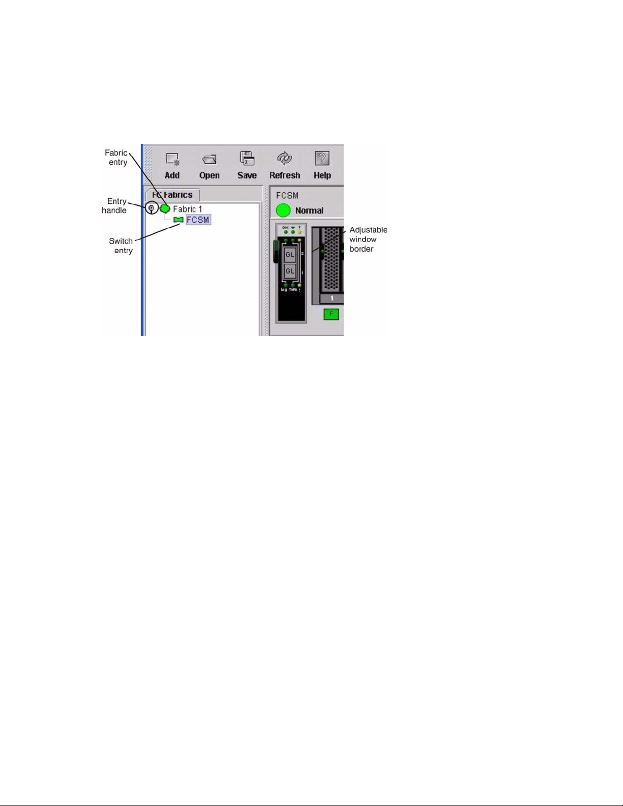
Fabric tree
The fabric tree, in the FC Fabric pane, lists the managed fabrics and their switch modules. To adjust the
window, click and drag the moveable window border. An entry handle to the left of an entry in the tree
indicates that you can expand the entry . When you click the handle or double-click the entry, the entry e xpands
to show its member switches. These fabric tree elements are shown in Figure 4.
Figure 4. Fabric tree
Each fabric tree entry has a small icon next to it that uses color to indicate the following operational status:
• A green switch module entry icon indicates that the switch is in normal operation.
• A red switch module entry icon indicates that the switch has a communications failure.
• A blue switch module entry icon indicates that the switch status is Unknown or that security is enabled on
the switch module but security is disabled on the fabric management switch.
• An amber switch module entry icon indicates that the sw itch is operational with errors.
You can use the fabric tree to access any fabric or switch module using the T opology or F aceplate window. Y ou
can click a fabric entry to open the T opology window from the fabric tree. You can click a switch module entry
to open the Faceplate window from the fabric tree.
Graphic window
The graphic window as shown in Figure 1 on page 74 shows graphic information about fabrics and switch
modules such as the fabric topology and the switch faceplate. To adjust the window length, click and drag the
window border that it shares with the data window.
Data window and tabs
The data window as shown in Figure 2 on page 74 displays a table of data and statistics associated with the
selected tab. Use th e scroll bar t o browse through the data. The window length can be adjusted by clicking and
dragging the border that it shares with the graphic window.
To adjust the column width, move the pointer over the column heading border shared by two columns until a
right/left arrow graphic is displayed. Click and drag the arrow to the desired width. The data window tabs
show options for the types of information that you can display in the data window. These options vary
depending on the display.
77

Working status indicator
The working status indicator as shown in Figure 1 on page 74 is in the lower-right corner of the Topology
window and shows when the network management workstation is exchanging information with the fabric. As
conditions change, the fabric forwards this information to the network management workstation where it is
reflected in the various displays.
Using the Topology window
The T opology window sho wn in Figure 5 on page 78 polls the selected fabric and displays its topology. switch
modules and interswitch links (ISL) are displayed in the graphic window and use color to indicate status. The
following functional elements are displayed in the T opology windo w when you click on the Data windo w tabs:
• Switch module and link status
• Working with switch modules and links
• Topology data windows
Figure 5. Topology window
78 Intel Blade Server Switch Module SBCEFCSW Management and User’s Guide

Fibre Channel switch module and link status
The Fibre Channel switch module icon shape and color provide information about the switch and its
operational state. In the Topology window, lines represent links between switch modules. See Table 16 for
Fibre Channel switch module and link status and “Fabric status” on page 86 for more information about other
Topology window icons.
Table 16. Fibre Channel switch module and link status indicators
Switch module icon color Status
Green Normal Fibre Channel switch operation
Amber Operational with errors
Red Inactive or Fibre Channel switch failure
Blue Unknown Fibre Channel device
Working with switch modules and links
Switch module and link icons are selectable and moveable and serve as access points for other windows and
menus. You select switch modules and links to display inform ati on, modify configurations, or delete them
from the window. The context-sensitive pop-up menus are accessible through the switch module and link
icons.
Click a switch module or link in the graphic window to display its status in the data window. To select multiple
switch modules or links, hold down the Ctrl key while selecting. When no switch modules or links are
selected, information about all switch modules is displayed. To deselect a switch module or link that is
currently selected, click the switch or link.
Different switch module icons will be displayed depending on the different switch vendor products present in
the attached fabric. See Table 17 on page 87 for a list of switch module icons and vendors. Attached switch
modules that are not manageable through the SAN Utility will be displayed as “third-party manageable”
switch icons. The topology configuration in Figure 6 on page 80 shows an example of a switch fabric with
third-party switch modules.
79
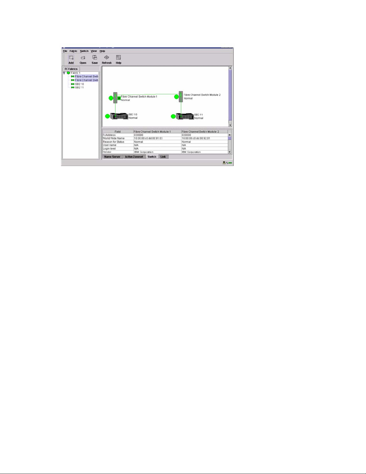
Figure 6. Switch fabric showing third-party manageable switch modules
Arranging switch modules in the window
You can use the following two methods to arrange individual switch module icons:
• To move an individual switch module icon, click and drag the icon to another location in the graphic
window. Li nks stretch or contract to remain connected.
• To arrange all switch module icons in the To pol ogy wi ndow, click
The Toggle Auto Layout check box in the View menu is selected by default so that the SAN Utility can
arrange the icons when you select Layout Topology.
You can save a custom arrangement, or layout, and restore that layout during a SAN Utility session. To create
a custom arrangement, arrange the icons; then, click View ” Remember Layout. To restore the saved layout,
click View, clear the Toggle Auto Layout check box, and click Layout Topology.
View ” Layout Topology.
Selecting switch modules and links
Selected switch module icons are highlighted in violet. Selected ISLs are highlighted in amber . You can select
switch modules and links by performing the following tasks:
• To select a switch module or a link, click the icon or link.
• To select multiple switch modules or links, hold down the Ctrl key and click the switch modules or links
that you want.
• To select all switch modules or links, right-click in the graphic window background. Click
Switches or click All Links
T o cancel a selection, press and hold the Ctrl ke y, and select the item again. To cancel multiple selections, click
in the graphic window background.
from the pop-up menu.
Select All
80 Intel Blade Server Switch Module SBCEFCSW Management and User’s Guide
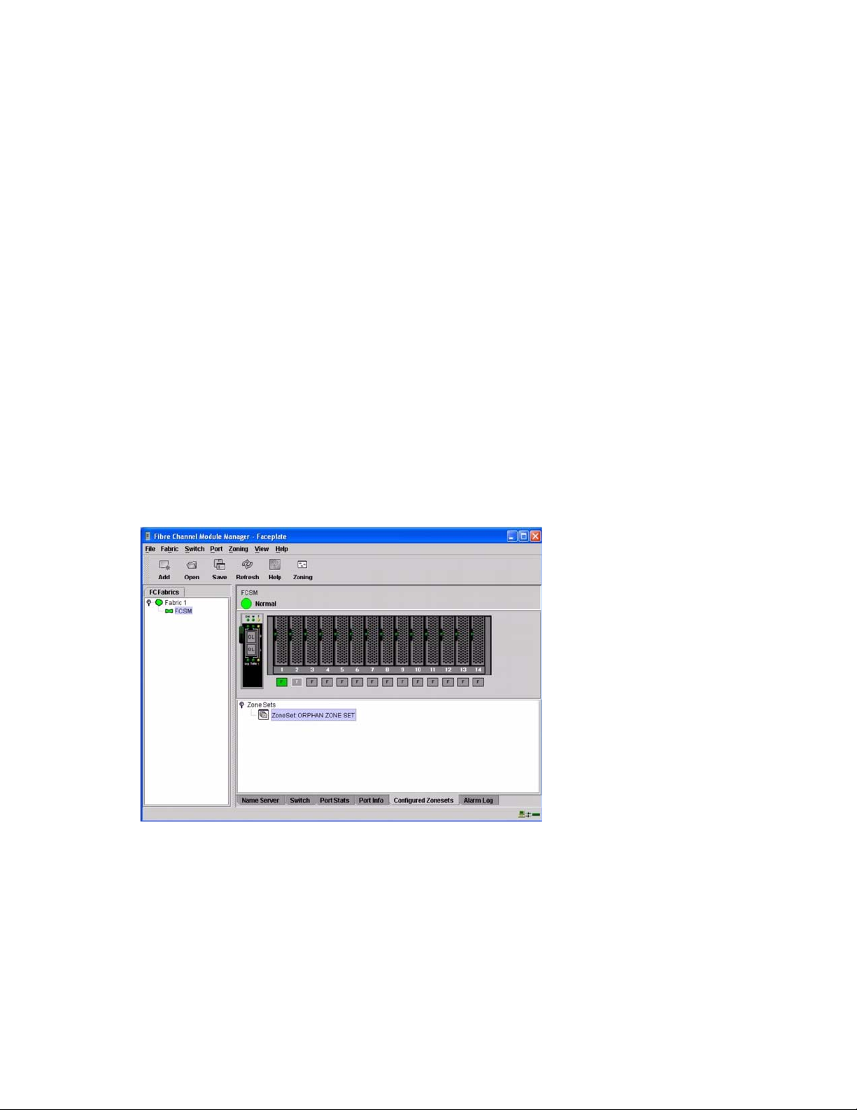
Topology data window tabs
The Topology Data window contains four tabs at the bottom of the window. When you click a tab, the
following information is displayed:
•
Name Server - Click the Name Server tab to display all devices that are logged with the name
server and their location within the current fabric configuration. See
on page 115 for more information about your configuration.
•
Active Zoneset - Click the Active Zoneset tab to display the active zone set for the fabric,
including zones and their member ports. See
information about this data window . See
and zones.
•
Switch - Click the Switch tab to display the current network and switch module configuration
data for the selected switches. See
•
Link - Click the Link tab to display the current link status for the selected switch modules in the fabric.
“Switch Data window” on page 100 for more information.
“Active Zoneset Data window” on page 88 for more
“Zoning a fabric” on page 88 for information about zone sets
“Name Server Data window”
Using the Faceplate window
The Faceplate window shown in Figure 7 and described in this section displays the switch module name and
operational state and the port status. The following functional elements are displayed in the Faceplate window
when you click on the Data window tabs:
• Port views and status
• Working with ports
• Faceplate data windows
Figure 7. Faceplate window
81

Opening the Faceplate window and pop-up menus
The Faceplate window shows the front of a single switch module and its ports. You can open the Faceplate
window and pop-up menus when you are in the Topology window by performing the following tasks:
• T o open the Faceplate windo w when vie wing the Topology window, click a switch module entry or icon in
the fabric tree, or double-click the switch module graphic.
• To open the fabric pop-up menu when viewing the Topology window, right-click the graphic wind ow
background. The fabric pop-up menu displays selections to refresh the fabric, select all switch modules,
select all links, or layout topology .
• To open the switch module pop-up menu when viewing the Topology window, right-click the switch
module icon in the graphic window. The switch pop-up menu displays selections to refresh the switch,
delete the switch from the display, open the Switch Properties window, or open the Network Properties
window.
• To open the link pop-up menu, right-click the link. The Link pop-up menu displays a selection to delete
the link from the display.
• To open a Faceplate window pop-up menu, right-click the faceplate graphic in the Graphic window. The
faceplate pop-up menu displays selections to refresh the switch module, select all ports, manage switch,
port, and network properties, extend credits, and run the Port Loopback tests.
Port views and status
Port color and text pr ovid es information about the port and its operational state. Green indicates that the port is
active, and gray indicates that the port is inactive. The Faceplate window displays the following views of port
status corresponding to the View menu options in the Faceplate window:
• Port mode
• Port state
• Port speed
• Port media
See “Monitoring port status” on page 110 for more information about these displays.
Working with ports
Ports are selectable and serve as access points for other windows and menus. You select ports to display
information about them in the data window or to modify them. You cannot use the SAN Utility to select
internal bays and external ports at the same time; you must select either internal bays or external ports.
Context-sensitive pop-up menus and properties windows are acces sible through the Faceplate windo w and port
icons.
Selecting ports
When you select a port, the port is highlighted with a white border. You can select ports in the following ways:
• To select one port, click the port in the Faceplate display.
• To select a range of either internal or external consecutive ports, select a port and then press and hold the
shift key and select another port. The application selects both end ports and all ports in between in port
number.
• To select several nonconsecutive ports, hold the Ctrl key while selecting ports.
• To select all external ports, right-click anywhere on the switch module faceplate, and select
Ports from the pop-up menu. To select all internal ports, click any blade server and select All
Ports
from the pop-up menu.
To cancel a selection, press and hold the Ctrl key and select it again.
Select All
82 Intel Blade Server Switch Module SBCEFCSW Management and User’s Guide

Opening pop-up menus
You can manage the switch module and its ports using the following methods:
• To open the pop-up menu, right-click anywhere in the graphic window. If no ports are selected, port
specific tasks are unavailable in the menu.
• To select one or more ports and open the Port pop-up menu, right-click a port.
Faceplate data window tabs
The Faceplate Data window contains six tabs at the bottom of the display. When you click a tab, the following
information is displayed:
•
Name Server - Click the Name Server tab to display all devices connected to the switch module that
are logged with the name server.
• Switch
• Port Statistics
• Port Information
• Configured Zonesets
• Alarm Log
- Click the Switch tab to display the current switch module configuration data.
- Click the Port Stats tab to display the port performance data for the selected port.
- Click the Port Info tab to display the port detail information for the selected port.
- Click the Configured Zonesets tab to display all zone sets, zones, and zone
membership in the zoning database.
- Click the Alarm Log tab to display the system error information.
Managing fabrics
This section describes the following four main tasks for managing fabrics:
• Setting up security
• Managing the fabric database
• Displaying fabric information
• Zoning a fabric
Setting up security
Access to a switch module and permission to configure a switch is managed through user accounts created by
a fabric administrator. A user account consists of an account name, a password, and an authority level. The
authority level determines whether an account can merely monitor the switch module and fabric activity (User
authority), or change switch module configurations (Administrative authority). See “User command” on page
62 for information about administrating user accounts.
Fabric security determines the enforcement of user accounts on a switch module. A fabric administrator can
enable or disable the fabric security on a switch module using the Set Setup System command.
If fabric security is disabled (default), you can use the SAN Utility to log in to a switch module without an
account name and password. The Login name and Password fields in the Add a Fabric window are ignored,
and you are granted Admin authority. If fabric security is enabled, you must enter an account name and
password to log in to a switch module and add the fabric to the workspace. Having successfully added a fabric,
you can perform only those tasks in the SAN Utility that are granted by the authority level for that account. All
switch modules in a fabric should use the same fabric security value. See “Set Setup command” on page 39 for
information about the System keyword and the Security Enable parameter.
✏ NOTE
A switch module supports a combined maximum of 15 active login sessions. This includes SAN
Utility in-band and out-of-band login attempts, Telnet out-of-band login attempts, and SNMP out-ofband login sessions. Of this 15, there can be a maximum of 10 SAN Utility login attempts included in
the 15 total attempts. Additional logins are refused.
83

Managing the fabric database
A fabric database contains the set of fabrics that you have added during a SAN Utility session. Initially, a
Topology window with an empty fabric database opens. This section describes the following fabric database
management tasks:
• Adding a fabric
• Removing a fabric
• Opening a fabric view file
• Saving a fabric view file
• Rediscovering a fabric
• Adding a new switch module to a fabric
• Replacing a failed switch module in a fabric
• Deleting switch modules and links
Adding a fabric
Complete the following steps to add a fabric to the database:
1. In the Faceplate window, click
The Add a New Fabric window opens, as shown in Figure 8.
Fabric / Add Fabric.
Figure 8. Add a New Fabric window
2. In the
3. In the
4. In the
Fabric name field, type a fabric name.
IP address field, type the IP address of the switch module through which to manage the fabric.
Login name field, type the initial default login ID, USERID. In the Password field, type
the initial default password, PASSW0RD (the sixth character is a zero, not the letter O). The user
ID and password are case sensitive.
✏ NOTE
The password is for the switch module and is stored in the switch firmware. You are not required to
type a user ID or password if security is disabled. See “Setting up security” on page 83. See “Set
Setup command” on page 39 for information about the Set Setup commands in the Telnet section to
log in, and obtain password and security information.
5. Click
Add fabric.
Removing a fabric
Complete the following steps to delete a fabric file from the database:
1. Select a fabric in the fabric tree.
2. In the Faceplate window, click
Fabric / Remove Fabric.
84 Intel Blade Server Switch Module SBCEFCSW Management and User’s Guide

Opening a fabric view file
Complete the following steps to open an existing fabric view file:
1. In the Faceplate window, click
If there is a change to the fabric you are using, you are prompted to save the changes to the view file
before opening a different view file.
The Open View window opens.
2. In the Op en View window, type the name of the file you want to open.
3. Type a file password if necessary.
4. Click
Load View File. If the fabric has changed, you are prompted to save th e file before opening the
new view.
File / Open View File, or click the Open icon.
Saving a fabric view file
Complete the following steps to save a fabric view file:
1. In the Faceplate window, click
The Save View window opens.
2. In the Save View window, type a new file name.
3. Click
4. Type a file password, if necessary.
OK.
File / Save View As or click the Save icon.
Rediscovering a fabric
After making changes or deleting switch modules from a fabric view, refresh the fabric configuration. Use the
Rediscover Fabric option to clear the current fabric information that is displayed and rediscover the switch
module information. To rediscover a fabric, in the Faceplate window, click Fabr ic / Rediscover Fabric.
Adding a new switch module to a fabric
After you install a switch module into your SBCE unit, the switch uses the default fabric configuration
settings. The default fabric configuration settings are as follows:
• Fabric zoning is sent to the switch module from the fabric.
• All external ports (0,15) are GL_Ports; all internal ports (1 through 14) are F_Ports.
• The default IP addresses are:
For switch module bay 3:
192.168.70.129
For switch module bay 4:
192.168.70.130
Complete the following steps to add a new switch module to a fabric and not make changes to the default
fabric configuration settings:
1. If the switch module is not new, to reset the switch to the factory configuration, in the Faceplate window,
click
Switch / Restore Factory Defaults.
2. If you want to manage the switch module through the Ethernet port, configure the network SNMP
configuration using the Network Properties window. For more information, see “Network properties” on
page 107.
3. Configure any special switch settings.
✏ NOTE
To prevent communication with other switch modules in the fabric unti l the new switch is
configured, in the Zoning Config window, click None in the Default Visibility field. For more
information, see “Zoning configuration” on page 90.
85

4. Connect the interswitch links (ISL), but do not connect the devices.
5. In the Port Properties window, configure the port types for the new switch (GL_Port, TL_Port, Donor).
6. Connect the Fibre Channel devices to the switch module.
7. In the Edit Zoning window, make the necessary zoning changes.
Replacing a failed switch module in a fabric
Complete the following steps to replace a failed switch module for which an archive is available. See
“Restoring a switch module” on page 128 and “Archiving a switch module” on page 108 for more information.
1. Remove the failed switch module. For more information, see the
2. Install the new replacement switch module. For more information, see the
3. Log in to the fabric through the replacement switch module. In the Topology window, select the
replacement switch module from the fabric tree.
4. Click
5. In the Restore Switch window, type a name or select the archived switch configuration file to copy to the
6. Click
Switch / Restore.
The Restore Switch window opens.
switch module. For more information, see “Archiving a switch module” on page 108.
OK to write the configuration file to the switch module.
Installation Guide.
Installation Guide.
Deleting switch modules and links from the Topology display
The SAN Utility does not automatically delete switch modules or links that have failed or that are physically
removed. In this case, you can delete switch modules and links in the T opology windo w to bring the display up
to date. If you delete a switch or a link that is still active, the SAN Utility restores it automatically. You can
also refresh the display.
Complete the following steps to delete a switch module in the Topology window:
1. Select one or more switch modules in the Topology window.
2. Click
Complete the following steps to delete a link:
1. Select one or more lin ks in the Topology window.
2. Click
Switch / Delete.
Switch / Delete.
Displaying fabric information
The Topology window is the primary tool for monitoring a fabric. The graphics window of the Topology
window provides status information for switch modules, interswitch links, and the Ethernet connection to the
network management workstation.
The data window tabs show name server, switch, and active zone set information. The Active Zoneset tab
shows the zone definitions for the active zone set. See “Switch Data window” on page 100 and “Name Server
Data window” on page 115 for information about the Switch Data and Name Server Data windows.
Fabric status
The fabric updates the Topology and Faceplate windows by forwarding changes in status to the network
management workstation as they occur. Use the fabric to update the display status, or you can refresh the
display at any time. To refresh the Topology window, use one of the following methods:
• In the Topology window, click
• Click
•Press the F5 key.
View / Refresh.
Refresh.
86 Intel Blade Server Switch Module SBCEFCSW Management and User’s Guide
 Loading...