

Page 1
A guide for technically qualified persons
Intel® Server Board S815EBM1
Quick Start Guide
Before You Begin
Emissions Disclaimer................................................................... 2
Safety Cautions............................................................................ 2
Items Provided on the Bootable CD-ROM................................... 2
Safety and Regulatory Compliance .............................................. 3
Minimum Hardware Requirements
Processor...................................................................................... 3
Memory........................................................................................ 3
Power Supply ............................................................................... 4
Server Board Components
Back Panel Connectors................................................................. 7
Front Panel Connectors................................................................ 8
Jumpers........................................................................................ 9
Installation Procedures
Installing Processors.................................................................... 10
Installing Memory....................................................................... 13
Installing the I/O Shield .............................................................. 14
Installing the Server Board.......................................................... 15
Connecting the IDE Drives..........................................................16
Getting Help................................................................................ 17
Translations of this guide are available at:
Übersetzungen dieses Handbuchs sind erhältlich bei:
Versiones traducidas de esta guía se encuentran disponibles en:
Des traductions de ce guide sont disponibles à l'adresse:
Le versioni tradotte di questa Guida sono disponibili presso:
As traduções deste guia estão disponíveis em:
http://support.intel.com/support/motherboards/server/S815EBM1/manual.htm
All rights reserved. No part of this document may be copied, or reproduced in any form, or by
any means without prior written consent of Intel.
Intel Corporation (Intel) makes no warranty of any kind with regard to this material, including,
but not limited to, the implied warranties of merchantability and fitness for a particular purpose.
Intel assumes no responsibility for any errors that may appear in this document. Intel makes
no commitment to update nor to keep current the information contained in this document.
Intel, Pentium and Celeron are trademarks or registered trademarks of Intel Corporation or its
subsidiaries in the United States and other countries.
†
Other names and brands may be claimed as the property of others.
Copyright © 2001, 2002 Intel Corporation.
Order Number: A67055-004
Page 2

Before You Begin
Emissions Disclaimer
To ensure EMC compliance with your l ocal regional rules and regulations, the
final configuration of your end system product may require additional EMC
compliance testing. For more i nf or m ation please contact your local Intel
Representative.
®
See the Intel
EMC regulatory compliance information. This board has been verified to
comply with FCC and other internati onal Class A emission requirements.
Safety Cautions
CAUTIONS
Server Board S815EBM1 Product Guide for product Safety and
Pressing the power button does not turn off power to this board.
Disconnect the serv er board f rom its power source and from any
telecommunications l i nks, networks, or modems before doing any of the
procedures described in this gui de. Failure to do this can result in
personal injury or equipment damage. S o m e circuitry on the server board
may continue to operate even though front panel power button is off.
Read and adhere to all warnings, cautions , and notices in this guide and
the documentation supplied with the chassis, power supply, and
accessory modules. If the instructions for t he chassis and power supply
are inconsistent with these instructions or the inst ructions for accessory
modules, contact t he supplier to find out how you can ensure that your
computer meets safet y and regulatory requirements.
Electrostatic di scharge (ESD) can damage server board components. Do
the described procedures only at an ESD workstation. If no such s tation
is available, you can provide some ESD protection by wearing an
antistatic wrist strap and attaching it to a metal part of the server chassis.
Items Provided on the Bootable CD-ROM
Intel Server Board S815EBM1 Product Guide
Software utilities
Server Product Informati on
Customer Support Information
Web Links
†
To view the product guide, boot to W indows
Windows 98 / Windows 2000 and use Adobe
2 Intel Server Board S815EBM1 Quick Start Guide
95/Windows NT† /
†
Acrobat†.
Page 3

Safety and Regulatory Compliance
See the Intel Server Board S815EBM1 Product Guide for product Safety and
EMC regulatory compliance i nformation.
Intended uses: This product was evaluated for use in servers that will be
installed in offices, computer rooms, and similar locations. Other uses require
further evaluation.
EMC testing: Before computer integration, make sure that the chassis, power
supply, and other modules have passed EMC testing using a server board with a
microprocessor from the same family (or higher) and operating at the same (or
higher) speed as the microprocessor used on this server boar d.
Server board diagram label provided: Place the label inside the chassis in an
easy-to-see location, preferably oriented similarly to the server board.
I/O panel label provided: Place the label on the I/ O shield. The cut outs are for
the top serial port and the parall e l port.
Minimum Hardware Requirements
To avoid integration difficulties and possible board damage, your system must
meet the following minimum requirements. For a list of qualified memory and
chassis components, as well as the latest list of supported processors see
http://support.intel.com/support/motherboards/server/S815EBM1/compat.htm
Processor
Intel® Pentium® III processor or Intel® Celeron™ processor.
NOTE
✏
While the board will electrically support all the proces sors listed at the
URL above, the thermal solution that ships with the S815EBM1 will only
function properly with processors that have an Integrated Heat Spreader
(IHS). If using a non-IHS processor, you must ensure your therm al
solution is designed for use with the processor.
Memory
The board supports 168-pin SDRAM DI MMs as defined below:
• 168-pin, 3.3 V SDRAM Dual I nline Memory Modules (DIMMs)
with gold-plated contacts
• Unbuffered single or double row DIMMs
133 MHz SDRAM up to two double r ow DI MMs, or one
double row DIMM and two single row DIMMs
100 MHz SDRAM up to three double row DI MMs
Mixed speed DIMM configuration will default to the slowest speed
DIMM installed
• Serial Presence Detect (SPD) memory
• Basic Non-SPD support
Intel Server Board S815EBM1 Quick Start Guide 3
Page 4

• Non-ECC and ECC DIMMs (ECC DIMMs will operate in
non-ECC mode only)
• Minimum system memory: 32 MB
• Maximum system memory: 512 MB
NOTE
✏
The BIOS cannot determine DIM M size or type when not initialized. I f
more than 512 MB system memory is installed, the BIOS displays a
message at boot indicati ng m em ory above 512 MB has not been
initialized. The mess age i ndi cates that additional information is available
in Setup. The first time the BIOS detects this c ondition, a pause follows
the message with the option to enter.
Setup or to <ESC> and continue to boot . The message continues to be
displayed at boot time as l ong as the condition exists, howev er, the BIOS
will not pause on subsequent detection. Setup displays the installed
memory configuration and shows memory above 512 MB as
“not initialized.”
Power Supply
†
If the Wake On LAN
(WOL) and Instantly Available t echnology features are
used, ensure that the power supply current required depends on the wake devices
supported. Please see the S815EBM 1 Technical Product Specification for more
details.
4 Intel Server Board S815EBM1 Quick Start Guide
Page 5
Server Board Components
USB
Devices
USB
Devices
A
B
C
X
W
V
U
T
S
R
J9H4
3
1
2-pin alternate
power LED/Sleep
connector
MK J GH
O
LPN
IR Module
Q
IRTX
Ground
IRRX
+5V
15
16
Ground
+5V
No
Connection
Reset
On
I
HD LED
1
2
Power LED
J9H3
D
E
F
OM13571
Intel Server Board S815EBM1 Quick Start Guide 5
Page 6

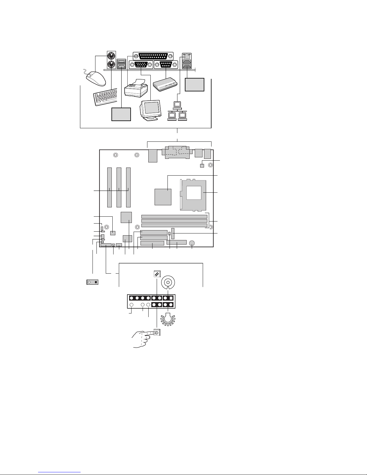
Server Board Components
A. Back panel connectors
B. Processor fan connect or (fan 1)
C. Intel
D. 370-pin processor socket
E. DIMM sockets
F. Battery
G. Speaker
H. Main power connector
I. Chassis fan (fan 3)
J. Floppy drive connector
K. Primary IDE connecto r
L. Secondary IDE connector
M. Intel
N. SMSC LPC47M132 Super I/O controller
O. Serial port B connector
P. SCSI hard drive activi ty LED connector
Q. Front panel switch/LED connector
R. Chassis intrusion connector
S. Alternate front panel power LED connector
T. System fan (fan 2)
U. BIOS configuration jumper block
V. Wake on LAN technology connector
W. 4 Mbit Firmware Hub (FWH)
X. PCI expansion slots
®
82815E Graphics Memory Controll er Hub (GM CH)
®
82801BA I/O Controller Hub (ICH2)
6 Intel Server Board S815EBM1 Quick Start Guide
Page 7

Back Panel Connectors
A
E
H
C
BF JGDI
OM12208
A. PS/2† mouse, green
B. PS/2 keyboard, purple
C. USB port 1
D. USB port 3
E. Parallel port, burgundy
F. VGA port, blue
G. Serial port A, teal
H. RJ-45 LAN connector with LED display
I. USB port 0
J. USB port 2
7 Intel Server Board S815EBM1 Quick Start Guide
Page 8

Front Panel Connectors
A
J9H4
13
B
15
16
DC
GHI
EF
1
2
15 1
J9H3
216
OM12281
A. Chassis intrusion c onnector
B. Reserved
C. Reset switch
D. Hard drive activity LED
E. Power LED
F. On/Off Switch
G. No connect
H. Ground
I. +5 V
8 Intel Server Board S815EBM1 Quick Start Guide
Page 9

Jumpers
13
J9G2
Function/Mode Jumper Setting Configuration
13
Normal 1-2
The BIOS uses current
configuration information and
passwords for booting.
OM12206
Configure 2-3
13
After the POST runs, Setup
runs automatically. The
maintenance menu is
displayed.
Recovery None
The BIOS attempts to
13
recover the BIOS
configuration. A recovery
diskette is required.
Intel Server Board S815EBM1 Quick Start Guide 9
Page 10

Installation Procedures
Installing Processors
NOTE
✏
Before installing a proces sor, make sure that it is com patible with this
board by checking this URL:
http://support.intel.com/support/motherboards/server/S815EBM1/
compat.htm
Also note that the thermal solution provided with this board is designed only for
use with processors that have an IHS.
I
II
10 Intel Server Board S815EBM1 Quick Start Guide
Page 11

III
IV
Intel Server Board S815EBM1 Quick Start Guide 11
Page 12

V
12 Intel Server Board S815EBM1 Quick Start Guide
Page 13

Installing Memory
The S815EBM1 board requires that DI MMs be installed as shown in the
following figure. The three DIM M sockets are arranged as Banks 0, 1, and 2 as
shown. If installing a single DIMM, install it in Bank 0. If installing two
DIMMs, install them in B anks 0 and 1.
0
2
OM12202
1
Intel Server Board S815EBM1 Quick Start Guide 13
Page 14

Installing the I/O Shield
The server board comes with an I/O shield for use in general purpose chassis. If
integrating this board in a 1U chassis, please obtain an I/O shield from the
chassis vendor. When installed in the chassis, the shield blocks radio frequency
transmissions, protects internal components from dust and foreign objects, and
promotes correct airflow within the chassis.
Install the I/O shield before installing the server board in the chassis. Place the
shield inside the chassis and press the shield into place so that i t fits tightly and
securely. If the shield doesn’t fit, obtain a properly-sized shield from the chassis
supplier.
14
.000
[0]
O.039
.884
[22.45]
0.276
[7.012]
.465
[11.811]
.567
[14.4]
DTL M
SHT 2
[1]
.063 .005
[1.6 0.12]
.787 .010 TYP
[20 0.254]
6.390 REF
[162.3]
DTL D
SHT 2
A
[0]
.000
.447
[11.345]
1.195
[30.36]
1.807
[45.892]
2.079
[52.804]
9
3.219
[81.768]
DTL P
SHT 2
5.010
[127.25]
8X R0.5 MIN
A
.567
[14.4]
Pictorial
View
OM12390
14 Intel Server Board S815EBM1 Quick Start Guide
Page 15

Installing the Server Board
Refer to your chassis manual for specific instructions on installing and removing
the server board.
Secure the server board to the chassis standoffs using six screws. Insert the
screws into the mounting holes as shown in the followi ng f igure.
OM12203
Intel Server Board S815EBM1 Quick Start Guide 15
Page 16

Connecting the IDE Drives
®
The Intel
boxed server board package includes a 40-contact or 80-conductor
IDE cable. It is capable of connecting two drives to t he server board. The cable
supports the Ultra UDMA-33and Ultra ATA-66/100 transfer protocols and is
backward compatible with drives using slower IDE transfer protocols.
For the cable to function correctly, you must do the following:
1 Attach the cable end with the single connector (A), which is blue and
labeled P1, to the server board.
2 Attach the cable end with the two closely- spaced connectors (B), to the
drives. The connectors are gray and black and are labeled P2 and P3.
3 If only installing one dri ve, only the end connector of the two
closely-spaced connectors should be attached to the dri ve (i.e. the one
labeled P3).
B
16 Intel Server Board S815EBM1 Quick Start Guide
A
OM12205
Page 17

Getting Help
World Wide Web
http://support.intel.com/support/motherboards/server/s815ebm1
Telephone
Talk to a Customer Support Technician* (Intel reserves the right to change
pricing for telephone support at any time without notice). Credit card calls billed
at U.S. $25 per incident, le vied in local currency at the applicable credit card
exchange rate plus applicable VAT (Intel reserves the right to change pricing for
telephone support at any time without notice).
In U.S. and Canada: 1-800-404-2284
In Europe:
UK 0870 6072439
France 01 41 918529
Germany 069 9509 6099
Italy 02 696 33276
Spain 91 377 8166
In Asia-Pacific region:
Australia 1800 649931
Hong Kong 852 2 844 4456
Korea 822 767 2595
PRC 800 820 1100
Singapore 65 831-1311
Taiwan 2 2718 9915
India 0006517-2-830 3634
In Japan:
0120-868686 (Domestic)
In Latin America:
Brazil
Mexico
Colombia
Costa Rica
Panama
Miami
Chile
Ecuador
(via AT&T)
0021-0811-408-5540
001-800-628-8686
980-9-122-118
0-800-011-0395
001-800-628-8686
1-800-621-8423
800-532-992
999-119, 800-628-8686
* Or contact your local dealer or distributor.
For an updated list of telephone number s , please see:
http://www.intel.com/support/9089.htm
Finland 9 693 79297
Denmark 38 487077
Norway 23 1620 50
Sweden 08 445 1251
Holland 020 487 4562
Indonesia 001-803 65 7249
Malaysia 1-800 80 1390
New Zealand 0800 444 365
Pakistan 632 6368415 IDD via Philippines
Philippines 1-800 1 651 0117
Thailand 001-800 6310003
Vietnam 632 6368416 IDD via Philippines
81-298-47-0800 (Outside country)
Guatemala
Venezuela
Argentina
(via AT&T)
Paraguay 008-11, 800-628-8686 (via AT&T)
Peru
Uruguay 000-410, 800-628-8686 (via AT&T)
99-99-190, 800-628-8686 (via AT&T)
800-11-120, 800-628-8686 (via AT&T)
001-800-222-1001, 800-628-8686
0-800-50000, 800-628-8686 (via AT&T)
Intel Server Board S815EBM1 Quick Start Guide 17
Page 18

Technical Training & Support
If you are registered in the Intel P roduct Dealer Program (North America), the
Genuine Intel Dealer Program (Asia-Pacific Region), or the Intel Product
Integrator Program (Europe/ Latin America), you are eligible for technical
training and support.
In U.S. and Canada: 1-800-538-3373, ext. 442 (M–F, 5:00 am–5:00 pm, PST)
In Europe: contact your distributor or fax your details to European Literature
on +44 (0) 1793 513142.
In Asia: +65-831-1379 (M–F, 8:30 am–5:30 pm, Singapore local time) or via
e-mail: APAC_gid@ccm.isin.intel.com
18 Intel Server Board S815EBM1 Quick Start Guide
 Loading...