

Page 1

Intel® Server System S7000FC4UR
Product Guide
A Guide for Technically Qualified Assemblers of Intel® Identified Subassemblies/Products
Intel Order Number D93989-002
Page 2

Disclaimer
Information in this document is provided in connection with Intel® products. No license, express or implied, by
estoppel or otherwise, to any intellectual property rights is granted by this document. Except as provided in Intel's
Terms and Conditions of Sale for such products, Intel assumes no liability whatsoever, and Intel disclaims any
express or implied warranty, relating to sale and/or use of Intel products including liability or warranties relating to
fitness for a particular purpose, merchantability, or infringement of any patent, copyright or other intellectual property
right. Intel products are not designed, intended or authorized for use in any medical, life saving, or life sustaining
applications or for any other application in which the failure of the Intel product could create a situation where
personal injury or death may occur. Intel may make changes to specifications and product descriptions at any time,
without notice.
Intel server boards contain a number of high-density VLSI and power delivery components that need adequate
airflow for cooling. Intel's own chassis are designed and tested to meet the intended thermal requirements of these
components when the fully integrated system is used together. It is the responsibility of the system integrator that
chooses not to use Intel developed server building blocks to consult vendor datasheets and operating parameters to
determine the amount of airflow required for their specific application and environmental conditions. Intel Corporation
can not be held responsible if components fail or the server board does not operate correctly when used outside any
of their published operating or non-operating limits.
Intel, Intel Pentium, and Intel Xeon are trademarks or registered trademarks of Intel Corporation or its subsidiaries in
the United States and other countries.
* Other names and brands may be claimed as the property of others.
Copyright © 2007, Intel Corporation. All Rights Reserved
ii Intel® Server System S7000FC4UR Product Guide
Page 3

Safety Information
Important Safety Instructions
Read all caution and safety statements in this document before performing any of the
instructions. See also Intel Server Boards and Server Chassis Safety Information on the
®
Server Deployment Toolkit CD 2 and/or at http://support.intel.com/support/
Intel
motherboards/server/sb/cs-010770.htm.
Wichtige Sicherheitshinweise
Lesen Sie zunächst sämtliche Warnund Sicherheitshinweise in diesem Dokument, bevor
Sie eine der Anweisungen ausführen. Beachten Sie hierzu auch die Sicherheitshinweise zu
Intel-Serverplatinen und Servergehäusen auf der Intel
oder unter http://support.intel.com/support/motherboards/server/sb/cs-010770.htm.
®
Server Deployment Toolkit CD 2
Consignes de sécurité
Lisez attention toutes les consignes de sécurité et les mises en garde indiquées dans ce
document avant de suivre toute instruction. Consultez Intel Server Boards and Server
Chassis Safety Information sur le Intel
vous sur le site http://support.intel.com/support/motherboards/server/sb/cs-010770.htm.
®
Server Deployment Toolkit CD 2 ou bien rendez-
Instrucciones de seguridad importantes
Lea todas las declaraciones de seguridad y precaución de este documento antes de realizar
cualquiera de las instrucciones. Vea Intel Server Boards and Server Chassis Safety
Information en el Intel
support/motherboards/server/sb/cs-010770.htm.
®
Server Deployment Toolkit CD 2 y/o en http://support.intel.com/
Page 4
Warnings
重要安全指导
Heed safety instructions: Before working with your server product, whether you are
using this guide or any other resource as a reference, pay close attention to the safety
instructions. You must adhere to the assembly instructions in this guide to ensure and
maintain compliance with existing product certifications and approvals. Use only the
described, regulated components specified in this guide. Use of other products /
components will void the UL listing and other regulatory approvals of the product and
will most likely result in noncompliance with product regulations in the region(s) in which
the product is sold.
System power on/off: The power button DOES NOT turn off the system AC power. To
remove power from system, you must unplug the AC power cord from the wall outlet.
Make sure the AC power cord is unplugged before you open the chassis, add, or remove
any components.
Hazardous conditions, devices and cables: Hazardous electrical conditions may be
present on power, telephone, and communication cables. Turn off the server and
disconnect the power cord, telecommunications systems, networks, and modems attached
to the server before opening it. Otherwise, personal injury or equipment damage can
result.
Electrostatic discharge (ESD) and ESD protection: ESD can damage drives, boards,
and other parts. We recommend that you perform all procedures in this chapter only at an
ESD workstation. If one is not available, provide some ESD protection by wearing an
antistatic wrist strap attached to chassis ground any unpainted metal surface on your
server when handling parts.
ESD and handling boards: Always handle boards carefully. They can be extremely
sensitive to ESD. Hold boards only by their edges. After removing a board from its
protective wrapper or from the server, place the board component side up on a grounded,
static free surface. Use a conductive foam pad if available but not the board wrapper. Do
not slide board over any surface.
iv Intel® Server System S7000FC4UR Product Guide
Page 5

Installing or removing jumpers: A jumper is a small plastic encased conductor that slips
over two jumper pins. Some jumpers have a small tab on top that you can grip with your
fingertips or with a pair of fine needle nosed pliers. If your jumpers do not have such a tab,
take care when using needle nosed pliers to remove or install a jumper; grip the narrow
sides of the jumper with the pliers, never the wide sides. Gripping the wide sides can
damage the contacts inside the jumper, causing intermittent problems with the function
controlled by that jumper. Take care to grip with, but not squeeze, the pliers or other tool
you use to remove a jumper, or you may bend or break the pins on the board.
Intel® Server System S7000FC4UR Product Guide v
Page 6

vi Intel® Server System S7000FC4UR Product Guide
Page 7

Preface
About this Manual
Thank you for purchasing and using the Intel® Server System S7000FC4UR.
This manual is written for system technicians who are responsible for troubleshooting,
upgrading, and repairing this server chassis. This document provides a brief overview of
the features of the chassis, a list of accessories or other components you may need,
troubleshooting information, and instructions on how to add and replace components on
the Intel
manual, see http://support.intel.com/support/motherboards/server/S7000FC4UR/.
Manual Organization
®
Server System S7000FC4UR Product Guide. For the latest version of this
• Chapter 1 provides an overview of the Server System S7000FC4UR. In this chapter,
you will find a list of the server board and chassis features, and product diagrams to
help you identify components and their locations.
• Chapter 2 describes how to start up and shut down the server.
• Chapter 3 describes the Intel
®
Server System S7000FC4UR Deployment Toolkit CD.
• Chapter 4 provides instructions for using the utilities that are shipped with the server
system or that you might need to download to update the system. This includes how
to navigate through the BIOS Setup screens, how to perform BIOS and firmware
updates, and how to configure the server management features.
• Chapter 5 provides instructions for adding and replacing hot-swappable and user-
serviceable system components and memory DIMMs. You do not need a service
technician to perform these tasks.
• Chapter 6 provides instructions for adding and replacing processors, memory,
boards, and other components that require a certified service technician.
At the back of this book, you will find POST code information, safety and regulatory
information, “getting help” information, and the warranty.
vii
Page 8

Additional Information and Software
If you need more information about this product or information about the accessories that
can be used with this server chassis, use the following resources. These files are available
at http://support.intel.com/support/motherboards/server/S7000FC4UR/
Unless otherwise indicated in the table below, once on this Web page, type the document
or software name in the search field at the left side of the screen and select the option to
search “This Product.”
Table 1. Additional Information and Software
For this information or
software
For in-depth technical
information about this
product, including BIOS
settings and chipset
information
If you just received this
product and need to install
it
Accessories or other Intel
server products
Hardware (peripheral
boards, adapter cards) and
operating systems that
have been tested with this
product
Processors that have been
tested with this product
DIMMs that have been
tested with this product
To make sure your system
falls within the allowed
power budget
For diagnostics test
software
For drivers Driver (for an extensive list of drivers available)
For firmware and BIOS
updates
For software to manage
your Intel
®
server
®
Intel
Server System S7000FC4UR Technical Product Specification
Intel® Server System S7000FC4UR Quick Start User's Guide in the
product box
Spares and Configuration Guide
Tested Hardware Operating Systems List
Supported Processors
Supported Memory
Power Budget
Platform Confidence Tests (PCT)
Operating System Driver (for operating system drivers)
Firmware Update
Intel System Management Software
Use this Document or Software
viii Intel® Server System S7000FC4UR Product Guide
Page 9

Contents
Safety Information ................................................................................iii
Important Safety Instructions ..........................................................................iii
Wichtige Sicherheitshinweise .........................................................................iii
Consignes de sécurité ....................................................................................iii
Instrucciones de seguridad importantes .........................................................iii
Warnings ........................................................................................................iv
Preface ..................................................................................................vii
About this Manual ..........................................................................................vii
Manual Organization .....................................................................................vii
Additional Information and Software .............................................................viii
Chapter 1: System Description .............................................................1
System Features ............................................................................................ 2
System Front .................................................................................................. 4
System Rear ................................................................................................. 10
Processors ................................................................................................... 12
System Memory ............................................................................................ 12
Power Subsystem ......................................................................................... 14
Cooling Subsystem ....................................................................................... 18
Hot-swap PCI Slots ...................................................................................... 19
Peripherals ................................................................................................... 20
System Board Set ........................................................................................ 22
Server and Platform Management ................................................................ 35
Front Control Panel ................................................................................ 5
Power Supply Modules ........................................................................ 14
Power Supply Consumption ................................................................. 16
Hot-Swap Hard Drive ........................................................................... 21
Optical Drive Bay ................................................................................. 22
5 ¼-inch Half-height Drive Bay ............................................................ 22
Main Board ........................................................................................... 23
Memory Board ...................................................................................... 28
I/O Riser Board (optional) .................................................................... 30
SAS Riser Board (optional) .................................................................. 31
Front Panel Board ................................................................................ 32
SAS Backplane Board .......................................................................... 33
Power Distribution Board ..................................................................... 35
Chapter 2: Starting Up and Shutting Down the Server ....................37
Powering Up the Server ............................................................................... 37
Intel® Server System S7000FC4UR Product Guide ix
Page 10

Shutting Down the Server .............................................................................37
Chapter 3: Intel® Server Deployment Toolkit .................................... 39
Chapter 4: Server Utilities .................................................................. 41
Using the BIOS Setup Utility .........................................................................41
Navigating the BIOS Setup Utility .........................................................41
System Configuration Reset .........................................................................43
Rolling BIOS ..................................................................................................45
Booting from Backup Image .................................................................45
Console Redirection ......................................................................................46
Serial Configuration Settings ................................................................46
Keystroke Mappings .............................................................................47
Limitations .............................................................................................48
Interface to Server Management ..........................................................48
Platform Confidence Test ..............................................................................49
Running the Platform Confidence Test .................................................50
Intel® Deployment Assistant .........................................................................51
System Setup and Configuration Utilities ......................................................51
Save and Restore System Configuration (SYSCFG) ...........................52
FWPIAUPD Firmware Load Utility ........................................................52
One-boot Flash Update Utility (OFU) ....................................................53
IFLASH32 BIOS Load Utility .................................................................53
FRUSDR Load Utility ............................................................................53
Extensible Firmware Interface (EFI) Shell .....................................................54
Chapter 5: User-Serviceable Components ....................................... 57
Before You Begin ..........................................................................................57
Tools and Supplies Needed ..................................................................57
System References ..............................................................................57
Removing and Installing the Chassis Cover .................................................57
Removing the Top Cover ......................................................................58
Installing the Top Cover ........................................................................59
Hot-swapping a Front System Fan ................................................................59
Hot-swapping a Rear System Fan ................................................................60
Hot-swapping a Hard Drive ...........................................................................62
Removing a Hard Drive Carrier ............................................................63
Mounting a Hard Drive in a Carrier .......................................................63
Installing a Hard Drive Carrier ..............................................................65
Hot-swapping a Power Supply ......................................................................66
Installing and Removing PCI Express* Add-in Cards ...................................68
Removing a Hot-swap PCI Card, Operating System Interface .............69
Removing a Hot-swap PCI Card, Hardware Interface ..........................71
Installing a Hot-swap PCI Card .............................................................72
Removing a Non-hot-swap PCI Card ...................................................74
x Intel® Server System S7000FC4UR Product Guide
Page 11

Installing a Non-hot-swap PCI Card ..................................................... 75
Installing and Removing Memory Boards ..................................................... 75
Removing a Memory Board ................................................................. 76
Installing a Memory Board ................................................................... 78
Installing and Removing DIMMs ................................................................... 79
Installing DIMMs ................................................................................... 81
Removing DIMMs ................................................................................. 84
Chapter 6: Technician Maintenance ...................................................85
Before You Begin ......................................................................................... 85
Tools and Supplies Needed ................................................................. 85
System References .............................................................................. 85
Component Locations .......................................................................... 86
Removing and Installing the Top Cover ....................................................... 90
Removing the Top Cover ..................................................................... 90
Installing the Top Cover ....................................................................... 91
Removing and Installing the Processor Air Baffle ........................................ 92
Removing the Processor Air Baffle ...................................................... 92
Installing the Processor Air Baffle ........................................................ 94
Removing and Installing the Lower Air Baffle ............................................... 96
Removing the Lower Air Baffle ............................................................. 96
Installing the Lower Air Baffle ............................................................... 97
Installing and Removing the SAS Riser Board (optional) ............................. 98
Installing the SAS Riser Board ............................................................. 98
Removing the SAS Riser Board ........................................................... 99
Installing and Removing the Intel® RAID Activation Key and RAID DIMM 101
Installing the Intel® RAID Activation Key and RAID DIMM ................ 101
Removing the Intel® RAID Activation Key and RAID DIMM .............. 102
Installing and Removing the Intel® RAID Smart Battery AXXRSBBU4 ..... 104
Installing and Removing the CD-ROM / DVD-ROM Drive .......................... 104
Removing the CD-ROM / DVD-ROM Drive ........................................ 104
Installing a CD-ROM / DVD-ROM Drive ............................................. 106
Installing and Removing a 5 ¼-inch Peripheral Device .............................. 107
Installing a 5 ¼-inch Peripheral Device .............................................. 108
Removing a 5 ¼-inch Peripheral Device ............................................ 109
Servicing the Processors ............................................................................ 110
Handling the Intel
Installing and Removing a Processor Thermal Blank ................................. 111
Removing a Processor Thermal Blank ............................................... 111
Installing a Processor Thermal Blank ................................................. 112
Installing and Removing a Processor ......................................................... 113
Installing a Processor ......................................................................... 113
Removing a Processor ....................................................................... 115
Removing and Installing the Center Brace ................................................. 116
®
Xeon® Processor MP .......................................... 110
Intel® Server System S7000FC4UR Product Guide xi
Page 12

Removing the Center Brace ...............................................................116
Installing the Center Brace .................................................................117
Installing and Removing the I/O Riser Board ..............................................118
Installing the I/O Riser Board ..............................................................118
Removing the I/O Riser Board ............................................................118
Installing and Removing the Intel
®
Remote Management Module 2 (Intel®
RMM2) ................................................................................................119
Installing the Intel
Removing the Intel
®
RMM2 and NIC Module .......................................119
®
RMM2 and NIC Module .....................................121
Replacing the Main Board ...........................................................................122
Removing the Main Board ..................................................................122
Installing the Main Board ....................................................................124
Replacing the SAS Backplane Board ..........................................................127
Removing the SAS Backplane Board .................................................127
Installing the SAS Backplane Board ...................................................128
Replacing the Power Distribution Board .....................................................128
Removing the Power Distribution Board .............................................128
Installing the Power Distribution Board ...............................................130
Replacing the Front Panel Board ................................................................131
Removing the Front Panel Board .......................................................131
Installing the Front Panel Board .........................................................132
Replacing the CMOS Battery ......................................................................133
Appendix A: POST Codes ................................................................ 137
POST Progress Codes and Messages .......................................................137
POST Error Messages and Handling ..........................................................141
POST Error Beep Codes .............................................................................153
Appendix B: Installation / Assembly Safety Instructions .............. 155
English ........................................................................................................155
Deutsch .......................................................................................................157
Français ......................................................................................................159
Español .......................................................................................................161
Italiano .........................................................................................................163
Appendix C: Safety Information ....................................................... 167
English ........................................................................................................167
Server Safety Information ...................................................................167
Safety Warnings and Cautions ...........................................................167
Intended Application Uses ..................................................................168
Site Selection ......................................................................................168
Equipment Handling Practices ............................................................169
Power and Electrical Warnings ...........................................................169
System Access Warnings ...................................................................170
Rack Mount Warnings ........................................................................171
xii Intel® Server System S7000FC4UR Product Guide
Page 13

Electrostatic Discharge (ESD) ............................................................ 171
Other Hazards .................................................................................... 172
Sicherheitshinweise für den Server .................................................... 174
Sicherheitshinweise und Vorsichtsmaßnahmen ................................ 174
Zielbenutzer der Anwendung ............................................................. 175
Standortauswahl ................................................................................ 175
Handhabung von Geräten .................................................................. 176
Warnungen zu Netzspannung und Elektrizität ................................... 176
Warnhinweise für den Systemzugang ................................................ 177
Warnhinweise für Racks .................................................................... 178
Elektrostatische Entladungen (ESD) .................................................. 178
Andere Gefahren ................................................................................ 179
Français ...................................................................................................... 180
Consignes de sécurité sur le serveur ................................................. 180
Sécurité: avertissements et mises en garde ...................................... 180
Domaines d’utilisation prévus ............................................................ 181
Sélection d’un emplacement .............................................................. 181
Pratiques de manipulation de l’équipement ....................................... 181
Alimentation et avertissements en matière d’électricité ..................... 182
Avertissements sur l’accès au système ............................................. 183
Avertissements sur le montage en rack ............................................. 184
Décharges électrostatiques (ESD) ..................................................... 184
Autres risques .................................................................................... 185
Información de seguridad del servidor ............................................... 186
Advertencias y precauciones sobre seguridad .................................. 186
Aplicaciones y usos previstos ............................................................ 187
Selección de la ubicación ................................................................... 187
Manipulación del equipo .................................................................... 187
Advertencias de alimentación y eléctricas ......................................... 188
Advertencias el acceso al sistema ..................................................... 189
Advertencias sobre el montaje en bastidor ........................................ 190
Descarga electrostática (ESD) ........................................................... 190
Appendix D: Regulatory and Compliance Information ..................197
Product Regulatory Compliance ................................................................. 197
Product Safety Compliance ................................................................ 197
Product EMC Compliance - Class A Compliance .............................. 197
Certifications / Registrations / Declarations ....................................... 198
Product Regulatory Compliance Markings ......................................... 198
Electromagnetic Compatibility Notices ....................................................... 200
FCC Verification Statement (USA) ..................................................... 200
Industry Canada (ICES-003) .............................................................. 201
Europe (CE Declaration of Conformity) .............................................. 201
VCCI (Japan) ..................................................................................... 201
Intel® Server System S7000FC4UR Product Guide xiii
Page 14

BSMI (Taiwan) ....................................................................................202
RRL (Korea) ........................................................................................202
CNCA (CCC China) ............................................................................202
Regulated Specified Components ...............................................................203
Restriction of Hazardous Substances (RoHS) Compliance ........................203
End of Life / Product Recycling ...................................................................204
Appendix E: Equipment Log ............................................................ 205
Appendix F: Warranty ....................................................................... 207
Limited Warranty for Intel® Chassis Subassembly Products ......................207
Extent of Limited Warranty ..........................................................................208
Warranty Limitations and Exclusions ..........................................................208
Limitations of Liability ..........................................................................208
How to Obtain Warranty Service .................................................................209
Telephone Support .............................................................................209
Returning a Defective Product ............................................................209
Appendix G: Getting Help ................................................................. 211
World Wide Web .........................................................................................211
Telephone ...................................................................................................211
xiv Intel® Server System S7000FC4UR Product Guide
Page 15

List of Figures
Figure 1. Intel® Server System S7000FC4UR ................................................... 1
Figure 2. Front Components.............................................................................. 4
Figure 3. Front Panel Controls and Indicators ................................................... 6
Figure 4. Intel
Figure 5. System Rear..................................................................................... 12
Figure 6. Memory Boards ................................................................................ 13
Figure 7. Power Supply Indicators................................................................... 15
Figure 8. Power Consumption Selection Jumper............................................. 16
Figure 9. Rear Fan Locations .......................................................................... 18
Figure 10. Peripheral Area............................................................................... 20
Figure 11. Hard Drive Carrier........................................................................... 21
Figure 12. DVD-ROM / CD-ROM Drive Carrier ............................................... 22
Figure 13. Block Diagram ................................................................................ 23
Figure 14. Main Board Component Locations ................................................. 24
Figure 15. Main Board Jumpers....................................................................... 27
Figure 16. Memory Board LEDs and Connectors............................................ 29
Figure 17. I/O Riser Board Connectors............................................................ 31
Figure 18. SAS Riser Connectors.................................................................... 32
Figure 19. Front Panel Board Component Locations....................................... 32
Figure 20. SAS Backplane Connectors (Interior Side)..................................... 34
Figure 21. SAS Backplane Connectors (Drive Bay Side) ................................ 35
Figure 22. Removing the Chassis Cover ......................................................... 58
Figure 23. Installing the Chassis Cover ........................................................... 59
Figure 24. Removing a Front System Fan....................................................... 60
Figure 25. System Fan Module Installation...................................................... 60
Figure 26. Removing a Rear System Fan........................................................ 61
Figure 27. Hard Drive Carrier........................................................................... 62
Figure 28. Removing a Hard Drive Carrier ...................................................... 63
Figure 29. Removing the Air Baffle from the Hard Drive Carrier...................... 64
Figure 30. Attaching the Hard Drive to the Carrier........................................... 64
Figure 31. Installing Hard Drive into Server..................................................... 65
Figure 32. Power Supply Indicators................................................................. 66
Figure 33. Removing a Power Supply ............................................................. 67
Figure 34. Installing a Power Supply ............................................................... 68
Figure 35. Removing a PCI Card..................................................................... 70
Figure 36. PCI Slot Attention Button................................................................ 71
Figure 37. Installing a PCI Add-in Card ........................................................... 73
Figure 38. Opening Memory Board Latches.................................................... 76
Figure 39. Removing a Memory Board............................................................ 77
Figure 40. Installing a Memory Board.............................................................. 78
Figure 41. Minimum Memory Population ......................................................... 79
Figure 42. Memory Board A and B Population ................................................ 80
®
Local Control Panel................................................................... 8
Intel® Server System S7000FC4UR Product Guide xv
Page 16

Figure 43. Memory Board A, B, C, D Population.............................................. 81
Figure 44. Remove Memory Board DIMM Cover ............................................. 82
Figure 45. Install DIMMs................................................................................... 83
Figure 46. Main Board Component Locations.................................................. 87
Figure 47. SAS Backplane Connectors (Interior Side) ..................................... 88
Figure 48. SAS Backplane Connectors (Drive Bay Side)................................. 89
Figure 49. Front Panel Board Component Locations ....................................... 89
Figure 50. Removing the Top Cover ................................................................ 91
Figure 51. Installing the Top Cover .................................................................. 92
Figure 52. Removing the Processor Air Baffle ................................................. 93
Figure 53. Installing the Processor Air Baffle ................................................... 94
Figure 54. Engaging the Processor Air Baffle Guides...................................... 95
Figure 55. Removing the Lower Center Air Baffle............................................ 96
Figure 56. Installing the Lower Center Air Baffle.............................................. 97
Figure 57. Installing SAS Riser Board .............................................................. 98
Figure 58. Connecting SAS and SES Cables to SAS Riser Board .................. 99
Figure 59. Disconnecting SAS and SES Cables from SAS Riser Board........ 100
Figure 60. Removing SAS Riser Board .......................................................... 100
Figure 61. Installing the Intel® RAID Activation Key and DIMM..................... 102
Figure 62. Removing the CD-ROM / DVD-ROM Drive Carrier from the Server 105
Figure 63. Removing the CD-ROM / DVD-ROM Drive from the Carrier......... 105
Figure 64. Assembling the CD-ROM / DVD-ROM Drive and Carrier.............. 106
Figure 65. Inserting the CD-ROM / DVD-ROM Drive Carrier into the System 107
Figure 66. Removing 5 ¼-inch Peripheral Device from Server ...................... 108
Figure 67. Installing 5 ¼ Peripheral Device into Server ................................. 109
Figure 68. Removing a Thermal Blank........................................................... 111
Figure 69. Installing a Thermal Blank............................................................. 112
Figure 70. Open Processor Socket Release Lever ........................................ 113
Figure 71. Set Processor into Socket............................................................. 114
Figure 72. Close Processor Socket Lever...................................................... 114
Figure 73. Open Processor Socket Release Lever ........................................ 115
Figure 74. Removing the Center Brace.......................................................... 116
Figure 75. Installing the Center Brace............................................................ 117
Figure 76. Attaching the EMI Gasket.............................................................. 120
Figure 77. Installing the RMM2 NIC ............................................................... 120
Figure 78. Installing the Intel
®
RMM2............................................................. 121
Figure 79. Removing the PCI Dividers ........................................................... 123
Figure 80. Removing the Main Board............................................................. 124
Figure 81. Installing the Main Board............................................................... 125
Figure 82. Installing the PCI Slot Dividers...................................................... 126
Figure 83. Power Distribution Cable Location on SAS Backplane ................. 129
Figure 84. Removing the Power Distribution Board ....................................... 130
Figure 85. Installing the Power Distribution Board ......................................... 131
Figure 86. Removing the Front Panel I/O Board ............................................ 132
Figure 87. Installing the Front Panel I/O Board .............................................. 133
Figure 88. Removing the Battery.................................................................... 135
xvi Intel® Server System S7000FC4UR Product Guide
Page 17

Tables
Table 1. Additional Information and Software .................................................. viii
Table 2. Chassis Features ................................................................................. 2
Table 3. System Status LED States ................................................................... 9
Table 4. Hot-swap PCI Slot Power and Attention LED .................................... 19
Table 5. Setup Menu Key Use ......................................................................... 42
Table 6. Console Redirection Escape Sequences ........................................... 47
Table 7. EFI Shell Commands ......................................................................... 54
Table 8. Port 80 POST Code LEDs ............................................................... 137
Table 9. POST Progress Codes and Messages ............................................ 138
Table 10. POST Error Manager Messages and Handling ............................. 142
Table 11. Beep Codes ................................................................................... 153
Table 12. Product Regulatory Compliance Markings ..................................... 198
Intel® Server System S7000FC4UR Product Guide xvii
Page 18

xviii Intel® Server System S7000FC4UR Product Guide
Page 19
1 System Description
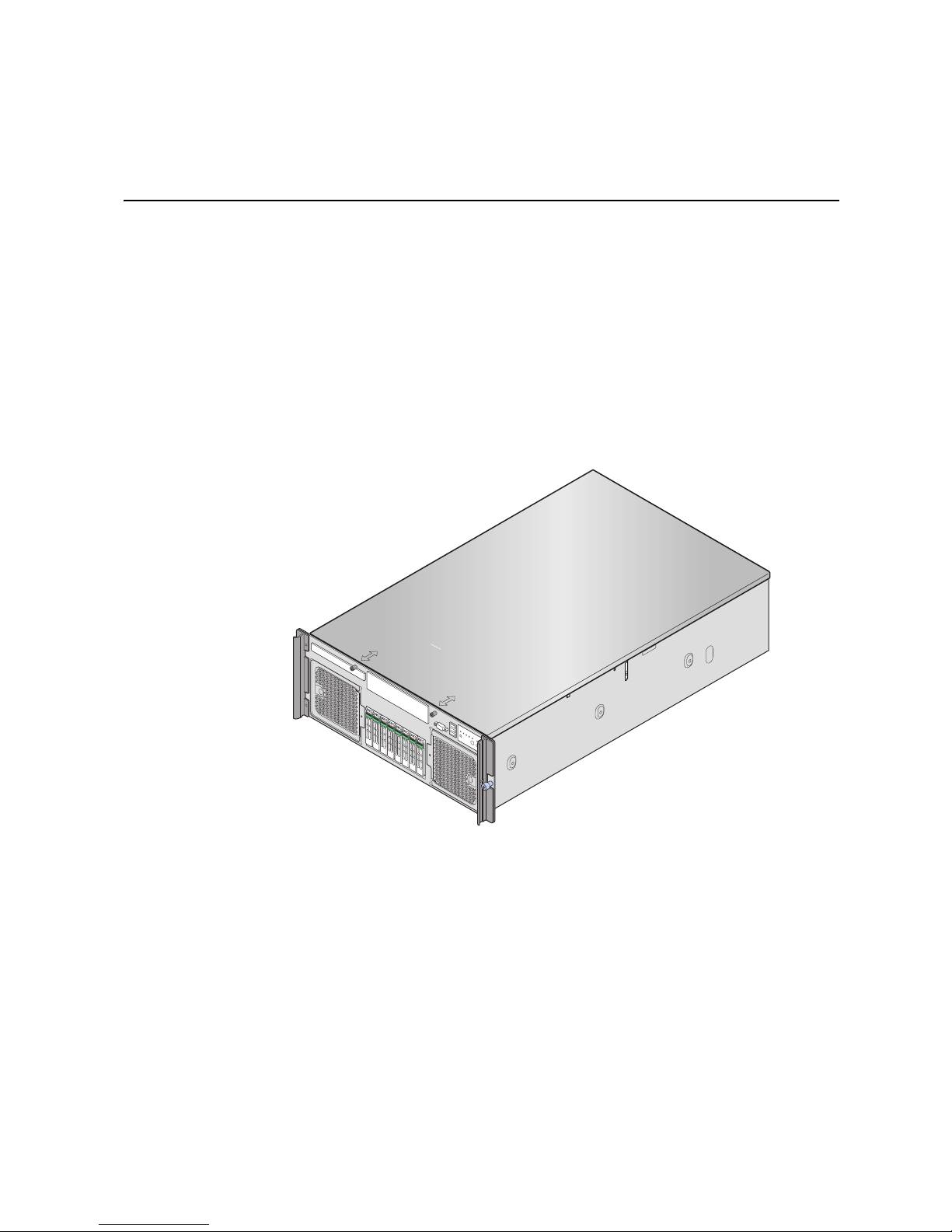
The Intel® Server System S7000FC4UR is a compact, high-density, 4U rack-mount
system with support for one to four Intel
533 MHz / 667 MHz FBDIMM memory. The system supports:
®
Xeon® processors MP and 256 GB of DDR2
• Hot-plug PCI Express* add-in cards
• Hot-swap, redundant power supply modules
• Hot-swap, redundant cooling fans
• Memory with RAS features
• Hot-swap hard drives
Figure 1. Intel
®
Server System S7000FC4UR
AF002228
1
Page 20

System Features
Feature Description
Dimensions Height: 6.8 inches (173 mm)
Clearance requirements Front clearance: 3 inches (76 mm)
Table 2. Chassis Features
Width: 17.6 inches (447 mm)
Depth: 27.8 inches (706 mm)
Weight of fully configured system: 90 lbs (40 kg)
Side clearance: 1 inch (25 mm)
Rear clearance: 6 inches (152 mm)
Configuration flexibility /
scaleability
Support for one to four processors
Support for at least two generations of processors
Support for up to four 2.5-inch SATA hard drives, or eight 2.5-
inch SAS hard drives with optional SAS riser board
Support for up to seven PCI-Express* adapters:
• Four x8 slots
• Three x4 slots
Support for up to 256 GB Fully Buffered DIMM (FBD) Double
Data Rate-2 (DDR2) 533 or 667 MHz memory
Support for two integrated gigabit LAN ports, or four integrated
gigabit LAN ports with optional I/O riser board
The optional Intel
display that allows you to configure and monitor the health of
the server independently from the operating system
Serviceability Front access to hot-swap hard drives
Front access to hot-swap fans
Rear access to hot-swap power supplies
System power and system status LEDs
System ID buttons and LEDs on front panel and rear of system
Memory status LEDs
Processor failure LEDs
Color-coded parts to identify hot-swap and non-hot-swap
serviceable components
®
Local Control Panel provides an LCD
2 Intel® Server System S7000FC4UR Product Guide
Page 21

Table 2. Chassis Features
Feature Description
Availability Two hot-plug PCI Express* slots.
Up to two 1570-watt power supplies in a redundant (1+1)
configuration. The second power supply is optional.
Dual power cords (1+1) when two power supplies are installed.
Up to eight hot-swap system fans in a redundant (7+1)
configuration. Two rear fans are optional; four rear fans are
required for redundancy.
Eight hot-swap 2.5-inch SAS hard drives.
SAS RAID riser board (optional) with a battery-backed DDR2
DIMM for disk cache.
Manageability Remote management
Emergency Management Port (EMP)
Intelligent Platform Management Interface (IPMI) 1.5 compliant,
partial IPMI 2.0 compliance
Wired For Management (WfM) 2.0 compliant
Remote diagnostics support
Optional Intel
KVM and media features (requires optional I/O riser)
®
Remote Management Module 2 provides remote
Front control panel System power button and LED
System reset button
NMI button
System ID button and LED
Optional Intel
®
Local Control Panel
System status LED
Hard drive status LED
LAN1 and LAN2 status LEDs
Video connector
Three USB 2.0 ports
Intel® Server System S7000FC4UR Product Guide 3
Page 22

System Front
A
B
C
G
Item Description
A CD-ROM / DVD-ROM drive bay
B 5 ¼-inch peripheral bay
C Video connector
E
D
FF
AF002229
D USB 2.0 ports
E Front control panel. Standard control panel shown.
F Hot-swap fan modules (2)
G Hot-swap hard drives (8)
Figure 2. Front Components
4 Intel® Server System S7000FC4UR Product Guide
Page 23
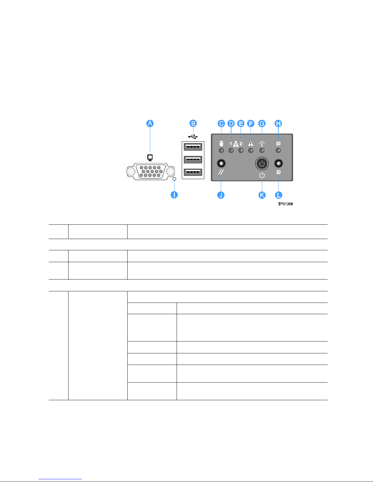
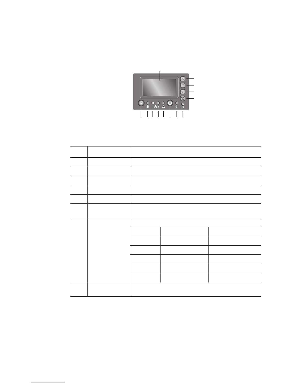
Front Control Panel
You can choose between the standard control panel or the Intel® Local Control Panel to
monitor and control your system locally.
The standard control panel provides the following user interface for system management
and status LEDs.
Item Feature Description
Front Panel Connectors
A Video connector Standard VGA-compatible video port
B Three USB
connectors
Front Panel Buttons and LED Indicators
C Hard drive activity
LED
2.0 port, 4-pin connectors
Green / amber LED that indicates hard drive activity and faults
LED State Drive State
Green on SAS drives are installed and functioning correctly
NOTE: LED may blink if all drives are active at the same
time.
Green blink SATA drives are installed and active
Amber on Drive / slot failure
Amber slow blink
(~1 Hz)
Amber fast blink
(~2.5 Hz)
Predictive hard drive / slot failure or rebuild in process
Rebuild interrupted or rebuild on empty slot
Intel® Server System S7000FC4UR Product Guide 5
Page 24
Item Feature Description
D
E
F System status / fault
G System power LED Green LED for system power status
LAN1, LAN 2 Status
LEDs
LED
Green LEDs
LAN1 shows status of either LAN port on the server board
LAN2 shows status of either LAN poor on the I/O riser board
LED State LAN State Activity
Off Idle No activity
Blinking Active Access
Green / amber LED for system status. See Table 3 for additional details.
LED System State Definition
Off Not ready AC power off
Green on Ok System is booted and ready
Green blink Degraded System is in a degraded
Amber blink Non-fatal System is likely to fail
Amber on Fatal System has failed
LED State System Power State ACPI
to operate
state
Off Power off No
On Power on No
Off S4 / S5 Yes
Blink S1 Yes
On S0 Yes
H System ID LED Blue ID that identifies the system through server management or locally
I NMI button Asserts NMI
J System reset button Press to reset the system
K System power button Press to turn the system power on or off
L System ID button Press to turn the system ID LED on or off
Figure 3. Front Panel Controls and Indicators
6 Intel® Server System S7000FC4UR Product Guide
Page 25
The optional Intel® Local Control Panel provides the following user interface for system
management and status LEDs.
A
B
C
D
E
M L K J I GH F
AF002230
Item Feature Description
A LCD display Video display
B Scroll up button Press to scroll up on the LCD
C Scroll down button Press to scroll down on the LCD
D Back button Press to move to the previous screen
E Select button Press to enter a command or select an option
F System ID LED Blue LED to identify the system through server management
software
G System power
LED
H System power
button
Green LED to show system status
LED State System Power State ACPI
Off Power off No
On Power on No
Off S4 / S5 Yes
Blink S1 Yes
On S0 Yes
Toggles system power on and off
Intel® Server System S7000FC4UR Product Guide 7
Page 26
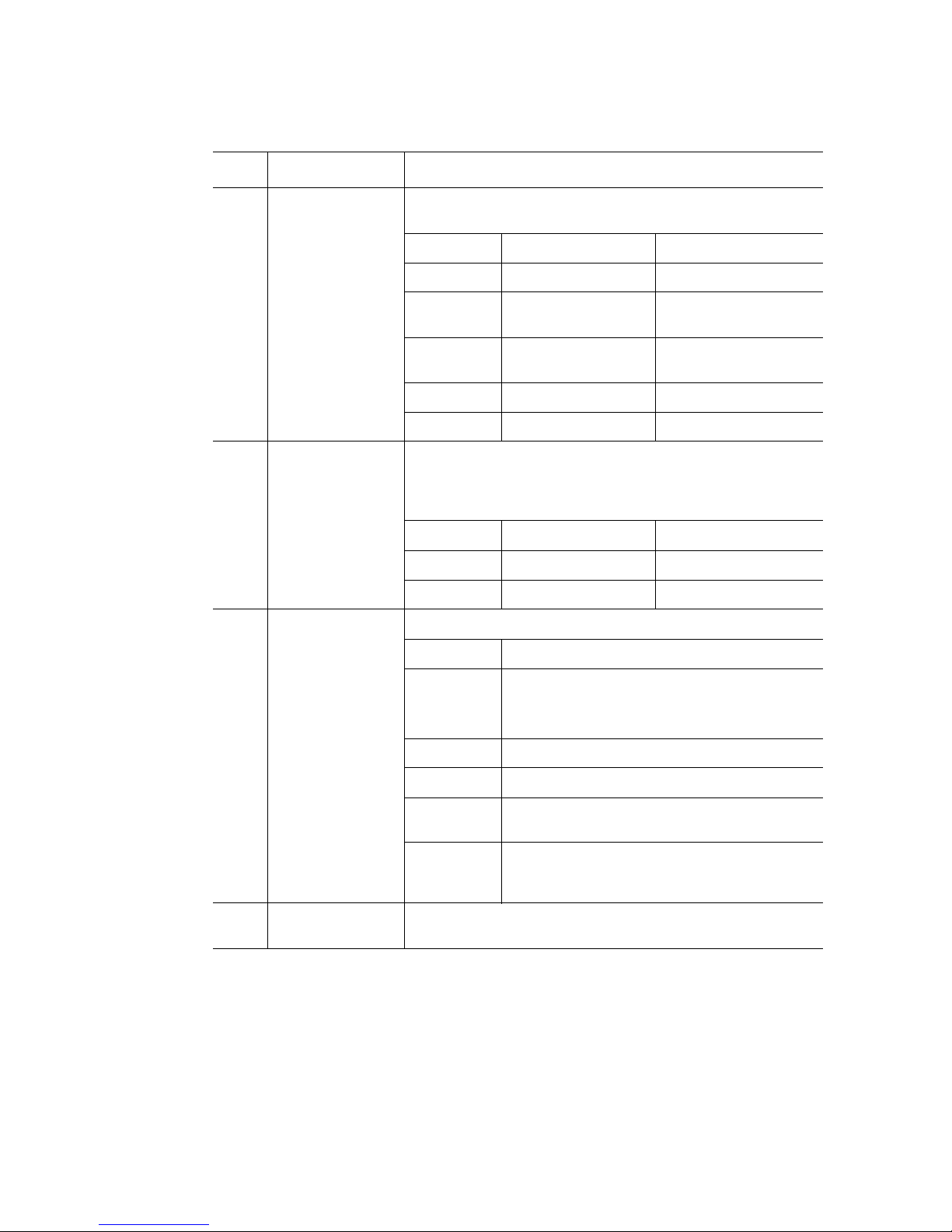
Item Feature Description
I System status /
fault LED
J
K
L Hard drive status
LAN1, LAN 2
Status LEDs
LED
Green / amber LED for system status. See Table 3 for additional
details.
LED System State Definition
Off Not ready AC power off
Green on Ok System is booted and
ready to operate
Green blink Degraded System is in a degraded
state
Amber blink Non-fatal System is likely to fail
Amber on Fatal System has failed
Green LEDs
LAN1 shows status of either LAN port on the server board
LAN2 shows status of either LAN poor on the I/O riser board
LED State LAN State Activity
Off Idle No activity
Blinking Active Access
Green / amber LED that indicates hard drive activity and faults
LED State Drive State
M System reset
button
Green on SAS drives are installed and functioning correctly
NOTE: LED may blink if all drives are active at
the same time.
Green blink SATA drives are installed and active
Amber on Drive / slot failure
Amber slow
blink (~1 Hz)
Amber fast
blink (~2.5
Hz)
Resets the system
Predictive hard drive / slot failure or rebuild in
process
Rebuild interrupted or rebuild on empty slot
Figure 4. Intel® Local Control Panel
8 Intel® Server System S7000FC4UR Product Guide
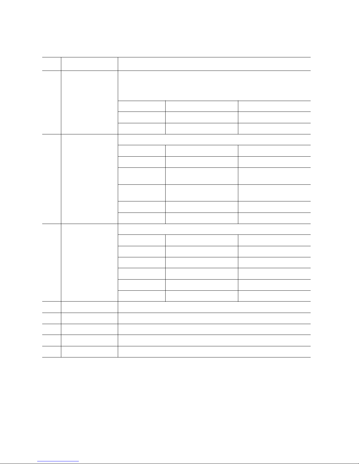
Page 27

Both the standard and Intel® Local Control Panel provide the same Status LED
information:
Table 3. System Status LED States
LED Color LED State System Status Description
Off N/A Not ready The AC power is off
Green On OK System is ready to operate
Green Blink Degraded The system is in a degraded state because
of:
• Unable to use all of the installed
memory when more than one DIMM is
installed
• More than 10 correctable memory
errors occurred and data is migrating
to a spare DIMM (memory sparing or
mirroring is enabled)
• Loss of system memory redundancy
(memory sparing or mirroring is
enabled)
• PCI Express* correctable link errors
• Loss of power supply or fan
redundancy
• Processor disabled
• Non-critical threshold crossed
(temperature, voltage, power nozzle,
power gauge, PROCHOT1)
• Battery failed
Amber Blink Non-fatal Non-fatal alarm. The system is likely to fail
because of:
• More than 10 correctable memory
errors occurred and in a nonredundant memory configuration
• PCI Express uncorrectable link errors
• Critical threshold crossed
(temperature, PROCHOT)
• VRD hot-asserted
• Minimum number of fans not present
or too many fans failed
Intel® Server System S7000FC4UR Product Guide 9
Page 28
LED Color LED State System Status Description
Amber On Fatal Fatal alarm. The system has failed or shut
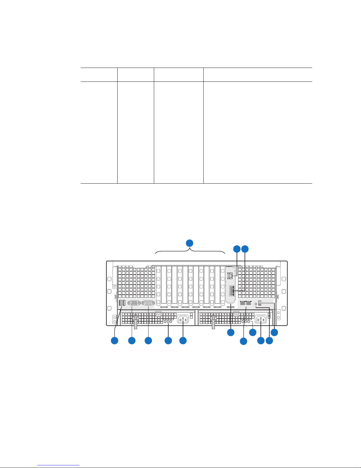
System Rear
This diagram shows the system with the optional I/O panel installed.
Table 3. System Status LED States
down because of:
• DIMM failure with only one DIMM
present / no good memory present.
• Run-time memory uncorrectable error
in non-redundant memory mode.
• CPU IERR signal asserted.
• No processor present or processor
configuration errors
• CPU THERMTRIP
• No power good / power fault
• Power unit redundancy sensor.
Insufficient resources offset. Not
enough power supplies present
A
B C
1743256
I N
D
F
E
G
H
K
L
J
M
AF002231
10 Intel® Server System S7000FC4UR Product Guide
Page 29
Item Description
A PCI slots
Slot 1 PCI Express* x8, hot-plug
Slot 2 PCI Express* x8, hot-plug
Slot 3 PCI Express* x8, not hot-plug
Slot 4 PCI Express* x8, not hot-plug
Slot 5 PCI Express* x4, not hot-plug
Slot 6 PCI Express* x4, not hot-plug
Slot 7 PCI Express* x4, not hot-plug
B Intel
®
Remote Management Module 2 (Intel® RMM2) NIC
C I/O riser Ethernet ports (two)
D USB ports (two)
E Standard VGA-compatible video port with 15-pin connector
F Serial port B connector
G Power supply LEDs
Power Supply LED Power Supply Status
Left: Power good (green) Power supply is on
Center: Fault (amber) Power supply failure
Right: AC OK (green) Power supply is connected to AC
H AC input power connector
I I/O riser card (optional)
J LAN 1 (left), LAN 2 (right) RJ45 Ethernet connectors
LAN Port LED LAN Status
Status LED (green) Off: No Ethernet connected
On: Ethernet link detected
Blink: Ethernet link active
Speed LED (green / amber) Off: 10 Mbps
Green: 100 Mbps
Amber: 1000 Mbps
Intel® Server System S7000FC4UR Product Guide 11
Page 30
Item Description
K Power supply LEDs
L AC input power connector
M System ID button
N Blue system ID LED to identify the system from among many systems
Processors
One to four 64-bit Intel® Xeon® processors MP are supported.
Power Supply LED Power Supply Status
Left: Power good (green) Power supply is on
Center: Fault (amber) Power supply failure
Right: AC OK (green) Power supply is connected to AC
Figure 5. System Rear
System Memory
The memory boards connect to the main board through x16 PCI Express* connectors. One
to four memory boards can be installed, two on each side of the system. Memory board
baffles are not needed for empty memory board slots, but DIMM blanks are required for
each socket on each memory board in which a DIMM is not installed.
12 Intel® Server System S7000FC4UR Product Guide
Page 31

AF002235
Figure 6. Memory Boards
Each memory board has these features:
• Supports up to eight FBD Generation-1 DIMMs
• Supports FBD speeds of 533MT/s (4-4-4, 5-5-5 latencies) and 667MT/s (5-5-5
latency)
• Supports FBDIMM configurations of x8, x4, single, dual-rank DDR2 DRAMs
• Supports DDR2 DRAM technologies of 512 Mbit, 1 Gbit, and 2 Gbit
• Supports Closed Loop Thermal Throttling with FBDIMM AMB temperature
sensors
• LED fault indicators for each DIMM
• One field replaceable unit (FRU) EEPROM
• Supports memory mirroring and memory sparing
See “Memory Board” on page 28 for additional information.
Intel® Server System S7000FC4UR Product Guide 13
Page 32

Power Subsystem
The power subsystem consists of:
• Power supply modules (see below)
• Power distribution board (see “Power Distribution Board” on page 35)
1+1 power supply redundancy or operation with a single power supply is supported under
all configurations at 220 VAC. At 100 or 115 VAC, 1+1 power supply redundancy or
operation with only one power supply is supported only if the power supply DC limits are
not exceeded.
If your desired configuration exceeds the power supply limits, two power supplies are
required. The two power supplies will operate in current-sharing mode to deliver the
additional power needed for your configuration. The two power supplies must be sourced
from separate AC circuits so they do not exceed maximum AC inlet current. Exceeding
the maximum AC inlet current may cause a circuit breaker to trip.
In a redundant configuration, the system supports one fault at a time, either one fan fault
or one power supply fault, and it supports hot-swapping one component at a time.
Power Supply Modules
The output rating of each power supply is 1570 watts when operated between 180 VAC
and 264 VAC. It is current-sharing with auto-ranging input. The power supply is 7.75
inches wide, 14.5 inches deep, and 1.47 inches high. The power supply modules have
universal AC input with Power Factor Correction (PFC) Distributed Power Supplies
(DPS). The AC input receptacle is an IEC-320 C14.
The power supply has DC outputs of 12 V and 3.3 VSB. The 12 V main power is
distributed through the server and is converted locally at the point-of-load using
embedded VRM converters. The power supply is capable of power-safe monitoring.
The maximum AC input current is:
• 100 - 127 VAC: 12 A
• 200 - 240 VAC: 7 A
The maximum input current listed is the maximum AC inlet current that can be drawn by
the power supply / supplies. If two power supplies are installed, then this value is the
maximum combined input current for both AC inlets.
In an N+1 configuration, the 12 VDC outputs have active (forced) current-sharing. The
two externally enabled outputs have these maximum ratings:
• +12 VDC: 121 A
• +3.3 VDCSB: 5 A
14 Intel® Server System S7000FC4UR Product Guide
Page 33

Each power supply module requires one power cord to supply AC power to the system.
One power supply ships with the standard system. When two power supply modules and
two power cords are installed, the system supports (1+1) power cord redundancy. This
allows the system to be powered by two separate AC sources. In the 1+1 configuration,
the system continues to operate without interruption if one of the AC power sources fails.
Each power supply module has three status LEDs next to the input connector.
A
B
C
AF002243
LED Location Purpose Description
A (left) Power Good LED (green) This green LED is driven by internal circuitry
and is lit whenever the power is turned on.
B (center) Fault LED (amber) This amber LED is driven by internal
circuitry and is lit when a power rail has
failed. The LED is lit even if the power
supply is in a latched state. The only time
(during a fault) when it is not lit is if the
+3.3VSB is lost.
The LED is not lit when the power supply is
turned off by powering down the system.
C (right) AC OK LED (green) This green LED is driven by internal circuitry
and is lit whenever the AC power cord is
plugged in to an active AC power source.
Figure 7. Power Supply Indicators
Intel® Server System S7000FC4UR Product Guide 15
Page 34

Note: The cooling system is non-redundant if only one power supply is installed.
Caution: Power supplies must be hot-swapped within two minutes. This time period applies only to
the time that the power supply is physically removed, not from the time of failure.
Power Supply Consumption
20A/110V
2
15A/100V
3
J6F1
Jumper J6F1 is used to set a threshold for power consumption when operating the server
with a single power supply on a low-line 100 / 110 / 115 / 120 / 127 VAC power circuit.
This threshold ensures the power consumption of the server does not exceed the power
that can be supplied by a single AC power circuit. When the system has two power
supplies, a separate AC power circuit is needed for each power supply to guarantee the
AC power circuit capability is not exceeded.
When a server is connected to low-line power, the J6F1 jumper sets these power
consumption thresholds:
• Pins 1-2 covered: Sets the power consumption threshold to 1180 watts
16 Intel® Server System S7000FC4UR Product Guide
AF002232
Figure 8. Power Consumption Selection Jumper
Page 35

• Pins 2-3 covered: Sets the power consumption threshold to 1030 watts
Power consumption is based on the power consumed within the system. Power factors for
inefficiency are not included in the above figures.
Servers connected to high-line power (200 / 208 / 220 / 230 / 240 VAC) do not have a
power consumption threshold. Under these conditions, jumper J6F1 should be set to:
• 100 / 110 VAC rated circuit: cover pins 2-3
• 115 / 120 / 127 VAC rated circuit: cover pins 1-2
• 200 / 208 / 220 / 230 / 240 VAC rated circuit: cover pins 1-2
The power consumption threshold is most likely to be exceeded when all of the following
conditions are met:
• The server is connected to a low-line power circuit
• The server has a single power supply installed
• The server is fully configured with four processors, 16 x4 GB DIMMs, and all PCI
slots are filled
• The server is running at maximum performance
If the power consumption threshold is crossed, the hardware throttles the processors to
reduce the power consumption to below the set threshold. The processor performance can
be returned to the full performance level by power cycling the server.
When two power supplies are installed, the required power is divided between them. By
using both circuits, the server can draw more power than the threshold limit for a single
power supply.
The hardware reduces the amount of power consumed if one of the power supplies fails.
This ensures the system consumes less power than the threshold from the single operating
power supply. When a failed power supply is replaced, the system is again able to share
the power load and operate at full performance.
If the J6F1 jumper is set incorrectly, the following may occur:
• If the jumper is covering pins 1-2 on a 100 / 110 VAC circuit, the server is allowed
to consume up to 1180 watts. This setting may cause a circuit breaker to trip.
• If the jumper is covering pins 2-3 on a 115 / 120 / 127 VAC circuit, the server power
consumption threshold is set to 1030 watts. The lower power threshold may be
exceeded, limiting system performance.
Intel® Server System S7000FC4UR Product Guide 17
Page 36

Cooling Subsystem
Caution: The chassis top cover must be installed for proper system cooling. Cooling components
must be hot-swapped within two minutes. This time period applies only to the time that the
cooling component is physically removed, not from the time of failure.
The cooling subsystem consists of hot-swap, redundant (7+1) fans. In a redundant
configuration, the system supports one fault at a time, either one fan fault or one power
supply fault, and it supports hot-swapping one component at a time. If a cooling
component fails, the system cooling is maintained and the system continues to operate
while the component is hot-swapped.
Each front fan assembly has one status LED. The LED is off when both fans are operating
normally. The LED illuminate amber if one or both of the fans fails. Failed front fans can
be hot-swapped from the front of the system.
Each rear fan has one status LED. The LED is off when the fan is operating normally and
illuminates amber if the fan fails. Failed rear fans can be replaced from the top of the
system when the top cover is removed.
18 Intel® Server System S7000FC4UR Product Guide
AF002242
Figure 9. Rear Fan Locations
Page 37

For proper processor cooling, the processor duct must always be in place. Systems that are
configured with fewer than four processors should have processor blanks installed to
maintain proper cooling.
Hot-swap PCI Slots
The two hot-swap PCI slots have power and attention LEDs. The attention button is used
to invoke a hot-swap sequence to remove or add an adapter without using the software
interface. The LEDs are identified by the green arrow on the PCI divider label.
Table 4. Hot-swap PCI Slot Power and Attention LED
Green Power LED State Definition
Off Power off: Power has been removed from the slot. A card can
On Power on: The slot is powered on. A card cannot be inserted or
Blinking Power transition: The slot is powering up or down. A card
Amber Attention LED
State
Off Normal: Normal operation.
On Attention: Power fault or operational problem has occurred with
Blinking Locate: The slot is being identified.
be inserted or removed.
removed.
cannot be inserted or removed.
Definition
this slot.
Note: If you hot-remove a PCI card without following the proper procedure, power is
automatically be turned off to the slot.
Intel® Server System S7000FC4UR Product Guide 19
Page 38

Peripherals
These peripheral devices are supported:
• Up to eight hot-swap 2.5-inch SAS hard drives or four 2.5-inch SATA hard drives
• One 1/2-inch IDE DVD-ROM / CD-ROM drive
• One 5 1/4-inch device bay
A
Item Description
A DVD-ROM / CD-ROM drive
B Tape drive (optional)
C Hard drives (eight)
B
C
Figure 10. Peripheral Area
AF002272
20 Intel® Server System S7000FC4UR Product Guide
Page 39

Hot-Swap Hard Drive
The hot-swap hard drive carrier and SAS backplane board accommodate 2.5-inch SAS or
SATA hard drives.
Item Description
A. Latch
C
B
A
AF002261
B. Green LED
Green on SAS drive is installed and working
Green blink Hard drive is active
C. Amber LED
Amber on Hard drive or slot failure
Amber slow blink (~1 Hz) Predictive hard drive / slot failure or rebuild
Amber fast blink (~2.5 Hz) Hard drive rebuild interrupted or rebuild on
correctly
is in process
empty slot
Figure 11. Hard Drive Carrier
Intel® Server System S7000FC4UR Product Guide 21
Page 40

Optical Drive Bay
The DVD-ROM / CD-ROM drive is installed in a sheet metal carrier that inserts from the
front of the system. You must power down the system and remove the top cover to remove
or install this device. A slimline IDE drive is supported if a SATA-to-IDE adapter board is
used. This board is connected to the drive and cabled to an internal SATA port on the main
board.
Figure 12. DVD-ROM / CD-ROM Drive Carrier
5 ¼-inch Half-height Drive Bay
The system supports one 5 ¼-inch, half-height device mounted at the front of the system.
A USB or SATA tape backup device can be cabled to the internal USB or SATA port
located on the main board. Alternatively, a SCSI or SAS tape backup device can be cabled
to a PCI Express* add-in card (not included).
System Board Set
The board set consists of these boards:
• Main board
• Memory boards
• I/O riser board (optional)
• SAS riser board (optional)
• Front panel board
• SAS backplane board
• Power distribution board
• SATA-to-IDE adapter board
22 Intel® Server System S7000FC4UR Product Guide
Page 41

Full Length Slot
Hot-Swap Capable
PCIe x8 (4Gb/s)
Slot # 1
Full Length Slot
Hot-Swap Capable
PCIe x8 (4Gb/s)
Slot # 2
Full Length Slot
PCIe x8 (4Gb/s)
Slot # 3
Half Length Slot
PCIe x8 (4Gb/s)
Slot # 4
Half Length Slot
PCIe x4 (2Gb/s)
Slot # 5
Note: x8 connector will be used for all x4 PCIe slots.
Full Length Slot
PCIe x4 (2Gb/s)
Slot # 6
Full Length Slot
PCIe x4 (2Gb/s)
Slot # 7
RAID
Battery
LSI* 1078
Controller
SAS and
DIMM VRs
RAID
Key
SAS Backplane
(8x 2.5” HS SAS HDD
SAS RAID5/6 DDR2 DIMM
SAS FW
SAS
Expander
Port # B
Port # C
Expander
Port # B
Port # C
CD-RW/DVD ROM
Note: PATA connector is
not on the baseboard.
SAS Riser
100-pin Front
Control Connector
Rear Video
Connector
PCIe
PCIe x8 (4Gb/s)
Port # A
PCIe
PCIe x8 (4Gb/s)
Port # A
PCIe x4 (2Gb/s)
SATA- PATA
Conversion
USB 2.0 Port # 6
Note: USB Hub on the Front
Panel I/O Board provides 3
Front Panel USB Ports
PCI 32-bit/33MHz
Misc.
A-Video #2
Video
(ATI RN50)
A-Video #1
Video Memory
(32 Mb, 16Mx16)
SATA # 0
(133 Mb/s)
1067 MT/s
Port #
4 and 5
Port #
6 and 7
Port # 1
1067 MT/s
North
Bridge
PE2
PE0 Port #
PE2
USB 2.0 Port # 2
USB 2.0 Port # 3
Rear
Rear
USB
USB
1067 MT/s
Port
Port
# 2
# 0
PCIe x4 (2 Gb/s)
Port #
4L (x4)
3 (ESI)
ESB2E
USB 2.0 Port # 4
Internal
USB
Header
CPU 1CPU 2CPU 3CPU 4
1067 MT/s
FSB 0FSB 1FSB 3FSB 2
FBD Channel 0
FBD 0
FBD Channel 1
FBD 1
FBD Channel 2
FBD 2
FBD Channel 3
FBD 3
Port
# 3
PCIe x4 “ESI” (2 Gb/s)
SATA # 5
SATA # 1-4
Internal
4
SATA
SATA
Ports
Memory
Memory
Riser A
Riser B
FBD DDR2
FBD DDR2
533/667
533/667
TPM
(ST Micro ST19WP18-TPM-C)
LPC
EMP/SOL
Kumeran
PCIe x4 (2 Gb/s)
Expansion Bus
BMC SDRAM + Flash
USB 2.0 Port # 0
FMLs, IPMB, SMBusses
DVO, DDC
Memory
Memory
Riser C
Riser D
FBD DDR2
FBD DDR2
533/667
533/667
SIO3
(PC87427)
Dual
GB
PHY
(Gilgal)
Intel
82575EB
Gigabit
Ethernet
Controller
I/O Riser
RMM2/ASMI
Intel Remote Management Module
GCM3 PHY
(General
MII
Communications
Module #3)
X-BUS
Gbit LAN
Gbit LAN
Gbit LAN
Gbit LAN
10/100 LAN
AF002283
Flash
(28F320C3 4Mb)
Flash
(28F320C3 4Mb)
Serial Port
(Back Panel)
Serial Port
(Internal)
RJ45
RJ45
RJ45
RJ45
RJ45
Main Board
The main board contains:
• Chipset north and south bridge components
• Processor sockets
• Four memory board connectors
• Video components
• Trusted Platform Module
• BIOS Flash components
Intel® Server System S7000FC4UR Product Guide 23
Figure 13. Block Diagram
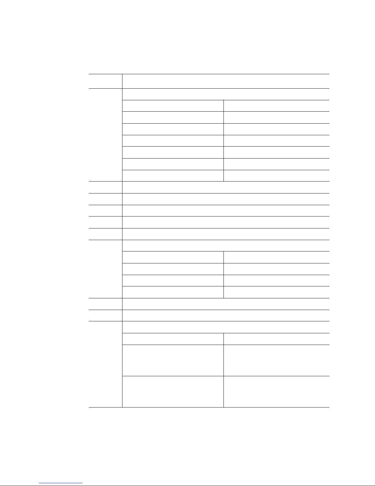
Page 42

• Super I/O*
• Seven PCI Express* slots
• Back panel I/O connectors
• Many voltage regulators used by the components
• Many of the primary voltage rails used by the rest of the board set
D
CC
AA
Z
X
BB
Y
W
V
A
B C E F G
H
J
I
K
M
L
N
O
P
Q
f
Item Description Item Description
A Dual Ethernet ports P Front panel connector
B I/O riser slot Q Power distribution board connectors
C PCI Express* x4 (slot 7) R Processor socket 1
D Serial Port A S Processor socket 2
24 Intel® Server System S7000FC4UR Product Guide
U
T S R
Figure 14. Main Board Component Locations
(3)
AF002275
Page 43

Item Description Item Description
E PCI Express x4 (slot 6) T Processor socket 3
F PCI Express x4 (slot 5) U Processor socket 4
G PCI Express x8 (slot 4) V SAS riser slot
H PCI Express x8 (slot 3) W Chassis intrusion
I PCI Express x8 hot-plug (slot 2) X 4-port SATA connector
J PCI Express x8 hot-plug (slot 1) Y Internal USB port
K Serial port B Z Memory board (slot C)
L Video port AA Single port SATA connectors
M USB 1 (top), USB 2 (bottom) BB Memory board (slot D)
N Memory board (slot A) CC Real-time clock battery
O Memory board (slot B)
Intel® Server System S7000FC4UR Product Guide 25
Page 44

A
C D
B
E
F
AF002276
Label Name Location Default Stuffed Jumper State
A Rolling BIOS J3D1 Empty
Stuff
B Password disable or clear J3C2 Stuff
Empty
C Clear CMOS / NVRAM J3C3 Stuff
Empty
D BMC force update J5C1 Stuff
Empty
E BMC flash write protect J6D1 Stuff
Empty
26 Intel® Server System S7000FC4UR Product Guide
1 - 2 = Force other bank
2 - 3 = Normal mode
1 - 2 = Password protect
2 - 3 = Password disabled / cleared
1 - 2 = Normal
2 - 3 = Forced CMOS / NVRAM clear
1 - 2 = Disable BMC force update
2 - 3 = Enable BMC force update
1 - 2 = Disable flash write protect
2 - 3 = Enable flash write protect
Page 45

Label Name Location Default Stuffed Jumper State
F Circuit breaker J6F1 Empty
Stuff
Figure 15. Main Board Jumpers
SATA Device Support
The ESB2 provides six Serial ATA (SATA) ports with a transfer rate of up to 3.0GB/s. The
main board has two internal, industry-standard 7-pin vertical SATA connectors that can be
cabled directly to a SATA device.
As an alternative to using a SAS riser to support eight SAS hard drives, an internal x4
8086 SAS/SATA connector is provided to cable to the SAS backplane board to support
four SATA hard drives. SATA cables should be 1 meter (40 inches) or less in length.
The ESB2 Port configuration is:
• SATA0 to SATA connector1 goes to the SATA-to-PATA converter board, then to the
optical drive
• SATA1 to x4 connector Port0 goes to SATA Drive 0 on the SAS backplane board
• SATA2 to x4 connector Port1 goes to SATA Drive 1 on the SAS backplane board
1 - 2 = 20A/110V (USA)
2 - 3 = 15A/100V (Japan)
• SATA3 to x4 connector Port2 goes to SATA Drive 2 on the SAS backplane board
• SATA4 to x4 connector Port3 goes to SATA Drive 3 on the SAS backplane board
• SATA5 to SATA connector2 is an extra port that could be used for a SATA tape drive
Intel® Server System S7000FC4UR Product Guide 27
Page 46

Video Support
The main board uses the ATI* RN50 Embedded Video Controller with 32 MB of video
RAM. The RN50 provides these features:
• 2D/3D video accelerator
• Dual DAC for simultaneous port support (front / rear video support)
• Resolutions from VGA up to UXGA (1600 x 1200)
• Digital Video Input/Output (DVI/DVO) interface routed to the Intel
Management Module 2 (Intel
• 3.3 V 32-bit / 33 MHz PCI host interface
The main board has a standard DB5 video connector.
Ethernet Support
1000/100/10 Ethernet capability is supported by the ESB2 MAC and 82563EB PHY
(Physical Layer). The ESB2 links to the PHY through a high-speed serial interface called
Kumeran. The Kumeran interface consists of two sets of Tx/Rx pairs for a total of eight
signals. The 82563EB PHY outputs two Gbit LAN ports and connects to a 1x2 RJ45 Gbit
connector that is accessible at the rear of the system.
®
®
RMM) for KVM support up to 165 MHZ
Remote
Memory Board
One, two, or four memory boards can be installed. Each memory board has eight DIMM
sockets that support x4 or x8, single- or dual-rank FBD DDR2 DIMMs. FBD speeds of
533 MT/s (4-4-4, 5-5-5 latencies) and 667 MT/s (5-5-5 latency) are supported. DDR2
DRAM technologies of 512 Mbit, 1 Gbit, and 2 Gbit are supported. The memory boards
connect to the main board through x16 PCI Express* connectors. The memory boards
have LEDs that indicate the status of the memory board power and the status of each
DIMM.
28 Intel® Server System S7000FC4UR Product Guide
Page 47

D
IHG
F
E
B
A
C
Q
P
O
N
M
L
K
J
Item Description
A Power Good LED (green). The memory board power is good
B DIMM1 Fault LED (amber). DIMM1 had an error and needs to be replaced
C DIMM2 Fault LED (amber). DIMM2 had an error and needs to be replaced
AF002246
D DIMM3 Fault LED (amber). DIMM3 had an error and needs to be replaced
E DIMM4 Fault LED (amber). DIMM4 had an error and needs to be replaced
F DIMM5 Fault LED (amber). DIMM5 had an error and needs to be replaced
G DIMM6 Fault LED (amber). DIMM6 had an error and needs to be replaced
H DIMM7 Fault LED (amber). DIMM7 had an error and needs to be replaced
I DIMM8 Fault LED (amber). DIMM8 had an error and needs to be replaced
J DIMM1 Socket
K DIMM2 Socket
L DIMM3 Socket
M DIMM4 Socket
N DIMM5 Socket
O DIMM6 Socket
P DIMM7 Socket
Q DIMM8 Socket
Figure 16. Memory Board LEDs and Connectors
Intel® Server System S7000FC4UR Product Guide 29
Page 48

I/O Riser Board (optional)
The I/O riser board is a vertical riser that provides advanced server management with a
dedicated maintenance Ethernet port, and additional dual-gigabit Ethernet ports.
®
The Intel
I/O riser board to provide an upgrade path to advanced server management capabilities.
When the optional Intel
features continue to work and additional functionality is available. This functionality
seamlessly integrates into the server, with respect to configuration functions and software
support.
The Intel
functionality, which lets the user use the remote system to control the host server.
The Intel 82575EB PCI Express*-based Ethernet controller provides advanced
networking control and capability with dual-gigabit Ethernet ports. This controller hosts
the Intel
optimization of the TCP flow. The Intel
A and / or port B in the BIOS. Server management traffic over these ports is not
supported. For management traffic, use the main board LAN ports.
Remote Management Module 2 (Intel® RMM2) and RMM2 NIC plug into the
®
RMM2 supports keyboard, mouse, video redirect, and media redirect
®
I/O Acceleration Technology II (Intel® I/OAT2) capability that provides
®
RMM2 is installed, the original set of server management
®
I/O riser provides an option to disable Gbit port
A
B
Item Description Item Description
A Intel
30 Intel® Server System S7000FC4UR Product Guide
®
RMM2 NIC C Dual gigabit LAN Ethernet ports
C
D
AF002241
Page 49

Item Description Item Description
BIntel
®
RMM2 NIC connector D Intel® Remote Management Module 2
SAS Riser Board (optional)
The SAS riser board works with the SAS backplane board to support eight SAS hard
drives. The SAS riser uses a dedicated slot at the front of the system to make cabling to
the SAS backplane convenient.
The SAS riser board uses the LSI1078* SAS controller to provide eight SAS channels at
up to 3Gb/s. The riser natively supports Integrated RAID levels 0, 1, and 1E.
®
If the optional Intel
installed, hardware RAID levels 0, 1, 5, 6, 10, 50, and 60 are enabled. The optional Intel
RAID smart battery can be installed to provide DDR2 DIMM refresh support during a
power failure.
RAID Activation Key and DDR2-667 registered DIMM are
connector
Figure 17. I/O Riser Board Connectors
B
A
C
D
®
E
AF002240
Intel® Server System S7000FC4UR Product Guide 31
Page 50

Item Description Item Description
A SES Connector D Intel
B SAS x4 Port A E Intel
C SAS x4 Port B
Front Panel Board
The front panel board provides access to the system video and USB interfaces. It also
interfaces to the Standard Control Panel or Intel
control modules contain the front panel buttons and LEDs.
®
RAID Activation Key
®
RAID DIMM Connector
Figure 18. SAS Riser Connectors
®
Local Control Panel module. The
A
B
Item Description
A Control panel connector
B Main board connector
C SAS backplane board connector
C
AF002262
Figure 19. Front Panel Board Component Locations
The front panel I/O board provides these functions:
• Main board to SAS backplane board signal interconnects
• Fan control
• USB hub, external front panel connector for three USB 2.0 ports and high-speed hub
controller to support the USB ports
32 Intel® Server System S7000FC4UR Product Guide
Page 51

• Video output and external front panel 15-pin VGA connector
• Speaker, audible beep-code and alarm speaker and speaker drive circuitry
• NMI button
SAS Backplane Board
The SAS backplane board performs the tasks associated with hot-swapping the hard
drives and enclosure monitoring and management. It provides these features and
functions:
• 3 Gbit SAS port expanders provide high-speed serial data paths from the hard drives
to the SAS riser board via two 4-port internal SAS cables.
• Eight blind-mate connectors mate with 2.5-inch SAS/SATA hard drives
• Vitesse* VSC-410 controller communicates drive presence and fault status
• Provides power and control for front system fans
• Provides power to DVD/CD-ROM device and tape device
Note: Because hard drives have different cooling, power, and vibration characteristics, Intel
validates specific hard drive types. See the Intel
®
Server System S7000FC4UR Tested
Hardware and Operating System List for a list of supported drives.
A
B
CED
F
Intel® Server System S7000FC4UR Product Guide 33
AF002227
Page 52

Item Description
A Power cable connector to CD-ROM / DVD-ROM drive and 5 ¼-inch peripheral
B Hot-swap cooling fan connector
C SAS x4 port B
D Power distribution board connector
E SAS x4 port A
F Front panel board connector
Figure 20. SAS Backplane Connectors (Interior Side)
G
H
I
J
K
L
NM
AF002226
34 Intel® Server System S7000FC4UR Product Guide
Page 53

G Hard Drive 0
H Hard Drive 1
I Hard Drive 2
J Hard Drive 3
K Hard Drive 4
L Hard Drive 5
M Hard Drive 6
N Hard Drive 7
Figure 21. SAS Backplane Connectors (Drive Bay Side)
Power Distribution Board
The power distribution board provides docking connectors for the hot-swap power supply
modules and it distributes power to the main board and the SAS backplane board. The
board contains EEPROM FRU information storage.
Item Description
Server and Platform Management
The server management embedded technologies include:
• Board instrumentation
• Sensors
• Interconnects
• Server management controllers
• Firmware algorithms
• System BIOS
The platform management system includes:
• Baseboard management controller (BMC)
• Watchdog timer
• Messaging support, including command bridging and user/session support
Intel® Server System S7000FC4UR Product Guide 35
Page 54

• Chassis device functionality, including power/reset control and BIOS boot flag
support
• Alert processing device, including platform event trap (PET) and Simple Network
Management Protocol (SNMP) alerts via LAN interfaces
• Platform event filtering (PEF) device
• SMTP (email alerting)
• Event receiver device. The BMC receives and processes events from other
subsystems.
• Field replaceable unit (FRU) inventory device functionality
• System event log (SEL) device functionality
• Sensor device record (SDR) repository device functionality
• Sensor device and sensor scanning / monitoring
• LAN interface that supports the IPMI-over-LAN protocol (RMCP, RMCP+)
• Serial-over-LAN (SOL)
• Chassis intrusion detection and chassis intrusion cable presence detection
• Support for the Intel
®
Remote Management Module 2
• Platform environment control interface (PECI) thermal management support
36 Intel® Server System S7000FC4UR Product Guide
Page 55

2 Starting Up and Shutting Down the
Server
Powering Up the Server
Press the power button on the front control panel. The fans start and POST begins.
Note: It might take three minutes or longer for video to be displayed, depending on the amount
of memory installed.
The server attempts to boot from the first device on the list of available devices in the boot
manager. If this device is not available, it will move to the second device. It continues
down the list until it reaches the first available device.
Shutting Down the Server
1. Exit the operating system if applicable.
2. Press and hold the power button until the server shuts down.
Caution: Powering down the server with the power button does not remove all power. The +3.3V
standby power is available even when the system is not running. To remove standby
power, unplug all power cords from the system.
37
Page 56

38 Intel® Server System S7000FC4UR Product Guide
Page 57

3 Intel
®
Server Deployment Toolkit
The Intel® Server System S7000FC4UR Server Deployment Toolkit CD provides these
contents for the Intel
• Utilities:
— SEL Viewer Utility
— Platform Confidence Tests
— System Configuration Utility (Syscfg)
—Intel
• Platform drivers for onboard devices
• Documentation, such as the Intel
document), and other user guide documents
• Adobe* Acrobat Reader
Booting the CD starts the Intel Deployment Assistant utility. Alternatively, the drivers,
utilities, and documentation content can be accessed through an HTML interface.
®
Server System S7000FC4UR:
®
Deployment Assistant
®
Server System S7000FC4UR Product Guide (this
39
Page 58

40 Intel® Server System S7000FC4UR Product Guide
Page 59

4 Server Utilities
Using the BIOS Setup Utility
The BIOS Setup Utility is a text-based utility that allows you to configure the system and
view and change device settings and view environmental information for the system. The
interface consists of several screens, called pages, each of which contains information or
links to other pages. The first page in Setup displays links for general categories. These
links lead to pages containing specific configuration settings.
The BIOS Setup Utility is functional through console redirection over various terminal
emulation standards. This may limit some functionality due to compatibility. For example,
colors, some keys or key sequences, and mouse support may be limited.
To enter the BIOS Setup Utility press <F2> when prompted during POST to access the
Systems Options Menu.
See “Additional Information and Software” for a link to the Technical Product
Specification where you will find details about specific BIOS setup screens.
Navigating the BIOS Setup Utility
The BIOS Setup Utility screens are divided into functional areas:
• The title bar is at the top of the screen and displays the page title. It might also
display navigational information.
• The Setup Item List is a set of controllable and informational items. Each item in the
list is in the left column of the screen. An item may also open a new window with
additional options.
• The Item Specific Help area is on the right side of the screen and contains help text
for the highlighted Setup Item. Help information might include the definition and
use of an item, allowable values, and effects of the options.
• The Keyboard Command Bar is at the bottom right of the screen. It continuously
displays help for special keys and navigation keys. The keyboard command bar is
41
Page 60

context-sensitive. It displays keys relevant to current page and mode. They keyboard
command bar supports these keys:.
Table 5. Setup Menu Key Use
Key Function Description
<Enter> Execute Command Press <Enter> to activate submenus when the
selected feature is a submenu, or to display a picklist if a selected feature has a value field, or to select
a sub-field for multi-valued features like time and
date. If a pick list is displayed, <Enter> will undo the
pick list, and allow another selection in the parent
menu.
<Esc> Exit <Esc> provides a way to back out of any field. This
key will undo the action of <Enter>. When the <Esc>
key is pressed while editing any field or selecting
features of a menu, the parent menu is re-entered.
When <Esc> is pressed in a submenu, the parent
menu is re-entered. When <Esc> is pressed in a
major menu, the exit confirmation window is
displayed and the user is asked whether changes
should be saved or discarded.
Up arrow Select item up The up arrow is used to select the previous value in
a menu item's option list, or a value field pick list.
Press <Enter> to activate the selected item.
Down arrow Select Item down The down arrow is used to select the next value in a
menu item's option list, or a value field pick list.
Press <Enter> to activate the selected item.
Left and right
arrows
<Tab> Select field Use <tab> to move between fields on a page.
<-> Change value The minus key changes the value of the selected
<+> Change value The plus key changes the value of the selected item
<F9> Setup defaults Pressing <F9> causes the following to appear:
Select menu The left and right arrow keys are used to move
between the major menu pages. The keys have no
affect if a submenu or pick list is displayed.
item to the previous value. This key scrolls through
the values in the associated pick list without
displaying the full list.
to the next value. This key scrolls through the values
in the associated pick list without displaying the full
list. On 106-key Japanese keyboards, the plus key
has a different scan code than the plus key on the
other keyboard, but it has the same effect.
Load default configuration now? [Y] [N]
If <Y> followed by <Enter> is pressed, all Setup
fields are set to their default values. If <N> followed
by <Enter> pressed, or if <Esc> is pressed, the user
is returned to where they were before <F9> was
pressed without affecting any field values.
42 Intel® Server System S7000FC4UR Product Guide
Page 61

Table 5. Setup Menu Key Use
Key Function Description
<F10> Save and exit Pressing <F10> causes the following to appear:
Each BIOS Setup Utility menu page contains a number of features. Some features are
used for informative purposes only, and other features are associated with a value field
that you can configure. Depending on the security option in effect, a menu feature's value
may be changeable. If a value cannot be changed, the value field for that feature is
inaccessible.
System Configuration Reset
You can restore the system configuration to the default values. When you reset the system
to the default values, The BIOS loads default system configuration values during the next
POST. Use one of these methods if you want to return to the defaults:
Save Configuration changes and exit
now? [Y] [N]
If <Y> followed by <Enter> is pressed, all changes
are saved and Setup is exited. If <N> followed by
<Enter> pressed, or if <Esc> is pressed, the user is
returned to where they were before <F10> was
pressed without affecting any existing values.
• Use <F9> in the BIOS Setup Utility.
• In the BIOS Setup Utility Exit menu, select “Load Default Values”.
• Use the main board CMOS/NVRAM Clear jumper (J3C3).
Note: Intel
NVRAM.
— Power down the system but do not remove the AC power cords.
— Move the NVRAM Clear jumper to enabled/clear CMOS (connect pins 2 and
3).
— Move the NVRAM Clear jumper to default/normal mode (connect pins 1 and 2).
— Power on the system.
®
Server System S7000FC4UR does not support any other mechanisms to clear
Intel® Server System S7000FC4UR Product Guide 43
Page 62

A
C D
B
E
F
AF002276
Label Name Location Default Stuffed Jumper State
A Rolling BIOS J3D1 Empty
Stuff
B Password disable or clear J3C2 Stuff
Empty
C Clear CMOS / NVRAM J3C3 Stuff
Empty
D BMC force update J5C1 Stuff
Empty
E BMC flash write protect J6D1 Stuff
Empty
F Circuit breaker J6F1 Empty
Stuff
1 - 2 = Force other bank
2 - 3 = Normal mode
1 - 2 = Password protect
2 - 3 = Password disabled / cleared
1 - 2 = Normal
2 - 3 = Forced CMOS / NVRAM clear
1 - 2 = Disable BMC force update
2 - 3 = Enable BMC force update
1 - 2 = Disable flash write protect
2 - 3 = Enable flash write protect
1 - 2 = 20A/110V (USA)
2 - 3 = 15A/100V (Japan)
44 Intel® Server System S7000FC4UR Product Guide
Page 63

Rolling BIOS
The rolling BIOS feature provides a fault-tolerant BIOS update mechanism. The BIOS
relies on specialized hardware and additional flash space to support the rolling BIOS
feature.
The Intel
store a separate BIOS image. The flash part that holds the BIOS image used to boot the
system is called the Primary Flash Bank. The second flash part holds the alternate or
backup BIOS image and is called the Secondary Flash Bank. All BIOS flash updates are
made to the Secondary Flash Bank.
The BIOS flash update process works like this:
1. Boot the system.
2. Use the EFI Flash or the Intel
3. Reset the system.
4. The rolling BIOS automatically:
— Boots the system with the old BIOS image.
— Validates the new BIOS image.
5. If the new image flashed successfully, then the BIOS automatically resets the
®
Server System S7000FC4UR supports two physical 4 MB flash parts that each
®
One Flash Update (OFU) utility to update the BIOS.
system and boots with the new BIOS image.
6. If the new BIOS image fails to boot, then the rolling BIOS boots with the old,
known-good BIOS image.
Booting from Backup Image
There are several possible scenarios in which a manual rollback to the previous BIOS
image might be necessary:
• The user successfully updated the BIOS but later learns that the new BIOS image
does not provide the desired functionality.
• The user successfully updated the BIOS but later changes the system configuration
in a way that causes the new BIOS to stop working.
• A power failure occurs during the flash update. The user reset the system and was
not able to boot to the new BIOS.
To boot from the backup image:
1. Power down the system, and remove the system cover.
2. Move the Rolling BIOS jumper to cover pins 1-2.
3. Plug in and boot the system. The system boots from the BIOS image stored on the
Secondary Flash Bank.
4. If the BIOS image in the other bank is corrupted or non-functional, perform a BIOS
update to overwrite this bad BIOS image.
Intel® Server System S7000FC4UR Product Guide 45
Page 64

5. Power down the system and move the Rolling BIOS jumper back to cover pins
2 - 3.
6. Replace the system cover, plug in the system, and boot it. The system boots from
the newly flashed image and a known-good backup image remains in the other
bank.
Console Redirection
The BIOS supports keyboard and video redirection through a serial link (COM port).
When console redirection is enabled, local (host server) keyboard input and video output
are passed to both the local keyboard and video connections and to the remote console
through the serial link. Keyboard inputs from both sources are valid and video is displayed
to both outputs.
With console redirection, the system can be operated without a host keyboard or monitor
and run entirely from a remote console. Setup and any other text-based utilities can be
accessed through console redirection.
Serial Configuration Settings
When redirecting through a modem instead of through a null modem cable, the modem
needs to be configured with:
• Auto-answer (Example: ATS0=2, to answer after two rings).
• Modem reaction to DTR set to return to command state (Example: AT&D1). Failure
to provide this results in the modem dropping the link when the server reboots, with
AT&D0, or becoming unresponsive to server baud rate changes, with AT&D2).
• Handshaking must be set to RTS/CTS + CD (carrier detect) for optimum
performance.
Handshaking must be set to Xon/Xoff + CD if the emergency management port
(EMP) shares the COM port with serial redirection. With this form of handshaking,
the server is prevented from sending video updates to a modem that is not connected
to a remote modem. If this is not selected, video update data being sent to the
modem inhibits many modems from answering an incoming call. An EMP option
utilizing CD should not be used if a modem is not used and the CD is not connected.
• Both the EMP and console redirection require N, 8, 1 mode (no parity, 8-bit data, 1
stop bit).
The BIOS does not require that the splash logo be turned off for console redirection to
function. The BIOS supports multiple consoles, some of which are in graphics mode and
some in text mode. The graphics consoles can display the logo while the text consoles
receive the redirected text.
Console redirection ends at the beginning of the Legacy OS boot (INT 19h).
46 Intel® Server System S7000FC4UR Product Guide
Page 65

Keystroke Mappings
During console redirection, the remote terminal, which may be a dumb terminal or a
system with a modem running a communication program, sends keystrokes to the local
server. The server passes video back over this same link. The keystroke mappings follow
VT-UTF8 format with the following extensions.
Setup Alias Keys
The <Del> and <Ctrl>-<function key> combinations are synonyms for the <F2> or
“Setup” key. These are not prompted for in screen messages. These hot keys are defined
only for console redirection support, and are not used on locally attached keyboards.
Standalone <Esc> Key for Headless Operation
To complete an escape sequence, the timeout must be two seconds for entering additional
characters following an escape.
• <Esc> followed by a two-second pause is interpreted as a single escape.
• <Esc> followed within two seconds by one or more characters that do not form a
sequence described in this document are interpreted as <Esc> plus the character or
characters, not as an escape sequence.
The following escape sequences are input sequences; they are sent to the BIOS from the
remote terminal.
Table 6. Console Redirection Escape Sequences
Escape Sequence Description
<Esc>R<Esc>r<Esc>R Defaults to
“disabled”.
<Esc>( BMC Mux Switch escape sequence
<Esc>CDZt<terminal-type-number> Dynamic terminal type choice
<Esc>-CDZ0 Inhibit console redirection
<Esc>-CDZ1 Restart console redirection
<Esc>-CDZ2 “Soft” inhibit console redirection without serial port or
Remote console reset
0 = PC-ANSI (the only current terminal type)
1 = VT100 (not implemented, but honored as VT100+)
2 = VT100+
3 = VT-UTF8
modem reset
Intel® Server System S7000FC4UR Product Guide 47
Page 66

Limitations
BIOS console redirection terminates after an EFI-aware operating system calls EFI Boot
Service ExitBootServices. The operating system is responsible for continuing the Console
Redirection after that point. BIOS console redirection is a text console. Graphical data,
such as a logo, are not redirected.
Interface to Server Management
If the BIOS determines that console redirection is enabled, it passes the baud rate through
the Intelligent Platform Management Bus (IPMB) to the appropriate management
controller.
Sample Setup for Console Redirection
Below is an example of how to configure the console/host and server for console
redirection. In this example, the console is running under Windows*. The console and
server are directly connected through the serial ports using a serial null modem cable.
Server Configuration
1. Power on the server.
2. When prompted, press <F2> to enter the System Options Menu.
3. Select the BIOS Setup menu.
4. Use the arrow keys move to the Server Management menu.
5. At the Server Management menu, select Console Redirection.
6. Select “COM1 Console Redirection”.
7. Set Console Redirect to “Enabled”.
8. Set the Bit Rate to “115.2K”.
9. Set the Flow Control to “RTS/CTS”.
10. Set the Terminal Type to “PC-ANSI”.
11. Press <F10>.
12. At the prompt to save changes and exit BIOS Setup, select “Yes” and press
13. Power down the server and configure the console.
Console Configuration
1. Boot the console into the operating system.
2. Click “Start” in the task bar.
3. Select Programs > Accessories > Communications. Click “Hyperterminal”.
4. At the Connection Description window, enter “guest” for the name and click “OK”.
<Enter>. The server reboots and console redirection is enabled.
48 Intel® Server System S7000FC4UR Product Guide
Page 67

5. At the Connect To window, select the COM port of the console where the null
modem is connected. In this example, it is COM1.
6. At the COM1 Properties window, select “115200” in the Bits per second (Baud
rate) box to match that which was configured on the server.
7. Select “Hardware” for the Flow Control to match that which was configured in
BIOS Setup (CTS/RTS is the hardware flow control).
8. Leave the default settings for the other boxes. Click “OK” to accept the settings and
enter the Hyperterminal screen.
9. Power on the server. The console displays the redirection after the video
synchronizes on the server.
Platform Confidence Test
The Platform Confidence Test (PCT) diagnostic utility is included on the Intel® Server
System S7000FC4UR Server Deployment Toolkit CD. It probes for the hardware at the
start of each test and reports the identified components. In this way, the PCT indirectly
identifies many assembly and cabling errors (broken or improperly seated cables) when
installed components are not reported. The test displays results for field replaceable units,
such as the processor modules, the server board, drives, and memory.
Three Platform Confidence Tests (PCT) are available. The duration of each test depends
on the number of processors and the amount of memory installed. On completion of each
test and after the test results are displayed, the program returns to the main menu.
Quick Test
The quick test checks the core components of the system to ensure they are functioning
properly. The test modules that are run during the quick test include:
• Cache
• MCH
• Memory
• Processor
• Real-time clock
Comprehensive Test
The comprehensive test performs a thorough test of the system components. The test
modules that are run during the comprehensive test include:
• Baseboard management controller
• Cache
• Graphics
• Hard drives
Intel® Server System S7000FC4UR Product Guide 49
Page 68

• ICHx
• Keyboard
• MCH
• Memory
• NIC
• PCI bus
• Processor
• SAS
• Super I/O
• Universal serial bus
The processor floating point unit (FPU) is tested and more extensive tests are run on the
memory and cache. Extensive tests are run on the onboard peripheral controllers,
integrated components, and the chipset.
Comprehensive Test with Continuous Looping
This is identical to the comprehensive test, but it runs continuously until the operator
interrupts the test cycle by pressing the <F10> key. The system transfers to the test menu
screen with the pass / fail status displayed, along with the number of test loops completed.
Running the Platform Confidence Test
1. Insert the Intel® Server System S7000FC4UR Server Deployment Toolkit CD into a
Windows*-based system.
2. Allow the autorun feature to launch the graphical user interface. If autorun does not
launch the GUI, launch it manually by double-clicking the CD-ROM drive.
3. From the Drivers and Utilities menu, choose “EFI” and then “Platform Diagnostics
Utility”.
4. Choose an appropriate option:
— If you want to run the Platform Diagnostics Utility from a CD, burn the *.iso
image to a CD.
— If you want to run the Platform Diagnostics Utility from a USB flash drive,
install the flash drive onto your system, open the *.zip file and copy the files to
the root of your USB flash drive.
5. Install the USB flash drive or the CD that contains the Platform Diagnostics utility
into your Intel
6. Press <F2> when prompted to enter the BIOS Setup utility.
7. From the BIOS Setup utility, go to the Boot Manager menu and choose “EFI Shell.”
®
Server System S7000FC4UR to be tested. Boot the system.
50 Intel® Server System S7000FC4UR Product Guide
Page 69

8. The Platform Diagnostics Utility starts to load and prompts you to respond to the
licensing agreement. Upon your agreement, the utility starts and you will see the
menu of test options.
Intel® Deployment Assistant
The Intel® Deployment Assistant provides a single interface with an easy to use HTMLlike graphical user interface to ease the process of setting up and deploying an Intel server
from initial boot through the initiation of an unattended OS installation. These setup and
deploy tasks can be performed with the Intel
• Update the system BIOS, firmware, and FRUSDR
• Configure server management settings
• Launch an unattended OS installation
®
The Intel
• Update an Intel server with the latest system software. Updates can be procured
Deployment Assistant will allow a system administrator to:
from a set URL (support.intel.com – which can be customized by OEM), a network
drive, or removable media (Intel
firmware components that can be updated using Intel
BIOS, ESB2, HSC, LCP, as well as SDRs.
®
Deployment Assistant:
®
Deployment Assistant CD or USB key). The
®
Deployment Assistant are:
• Configure the most common options of the BIOS and firmware.
• Configure a RAID volume on attached hard drives and install an operating system.
— The installation is fully unattended except for a license screen agreement that
the user needs to agree to.
— The latest drivers for all the on-board components can be inserted during the OS
installation
• Save SUP, driver updates, and chosen configuration settings in a profile for later use.
This allows quick restoration of the same server or “cloning” (migration of
configuration) to identical model servers.
System Setup and Configuration Utilities
Setup and configuration utilities are either on the Server Deployment Toolkit CD or the
®
Server Management Software CD, or included in the System Firmware Update
Intel
Package that is posted to http://support.intel.com/support/motherboards/server/
S7000FC4UR/
Available utilities for WinPE include:
• SELViewer
• Save and Restore System Configuration (SysConfig)
Intel® Server System S7000FC4UR Product Guide 51
Page 70

• FWPIAUPD Firmware Load utility
• iFlash32 BIOS Load utility
• FRUSDR Load utility
Available utilities for EFI include:
• SELViewer
• Save and Restore System Configuration (SysConfig)
• FWPIAUPD Firmware Load utility
• iFlash32 BIOS Load utility
• FRUSDR Load utility
Available utilities for Microsoft Windows Server 2003 include:
• One-Boot Flash Update (OFU)
Available utilities for Linux include:
• One-Boot Flash Update (OFU)
• Save and Restore System Configuration (SysConfig)
Save and Restore System Configuration (SYSCFG)
This command-line utility is used to:
• Save a subset of BIOS and firmware settings to a file.
• Write BIOS and firmware settings from a file to a server.
• Configure selected firmware settings.
• Configure selected BIOS CMOS settings.
• Change BIOS boot order.
• Display selected firmware settings.
• Display selected BIOS settings.
FWPIAUPD Firmware Load Utility
The Firmware Update utility updates these server management controllers:
• Baseboard management controller (BMC)
• Hot-swap controller (HSC)
• LCD control panel (LCP)
52 Intel® Server System S7000FC4UR Product Guide
Page 71

One-boot Flash Update Utility (OFU)
The One-Boot Flash Update (OFU) utility is an OS-present command-line utility that uses
configuration (CFG) files to allow users to update
• System BIOS
• Server management firmware of the baseboard management controller (BMC)
• Hot-swap controller (HSC) firmware
• Intel
®
Local Control Panel firmware
• Field replaceable units (FRU). Existing FRU data can also be modified.
• Sensor data records (SDR)
IFLASH32 BIOS Load Utility
Use the BIOS Update utility to upgrade the system BIOS. For information about the
rolling BIOS feature, see “Rolling BIOS” on page 45.
FRUSDR Load Utility
The FRUSDR Load utility updates and modifies the server management subsystem's
product level field replacement unit data and sensor data record repository, and displays
the System Management BIOS (SMBIOS) non-volatile storage components.
The FRU is initially factory-programmed and can be updated later by using the FRUSDR
utility to update specific FRU areas and fields. You cannot change the size of any FRU
area from the size defined in the original FRU Header.
Run the FRUSDR Load utility each time you upgrade or replace the hardware in your
server; excluding add-in cards, hard drives, fans, and RAM. The FRUSDR Load utility
programs the sensors that the server management software monitors.
With the FRUSDR Load Utility, you can:
• Discover the product configuration based on instructions in a master configuration
file.
• Display the FRU information.
• Update the non-volatile storage device associated with the baseboard management
controller (BMC) that holds the SDR and FRU information.
• Generically handle FRU devices that might not be associated with the BMC.
• Supply command lines and interactive input through the standard input device.
• View and direct results to the standard output device.
Intel® Server System S7000FC4UR Product Guide 53
Page 72

Extensible Firmware Interface (EFI) Shell
The EFI shell application allows other EFI applications to be launched, EFI device drivers
to be loaded, and operating systems to be booted. The combination of the EFI firmware
and the EFI Shell provides an environment that can be modified and adapted to many
hardware configurations.
The EFI shell provides a set of basic commands to manage files and EFI NVRAM shell
and boot variables. A list of these basic commands is in Table 7.
Extensive information is available on the EFI website at http://developer.intel.com/
technology/efi:
• For detailed information about the EFI shell, its commands, and the ability to
develop within the environment, see the EFI How-to Guide at http://
developer.intel.com/technology/efi/howto.htm.
• For a sample implementation, see http://developer.intel.com/technology/efi/
main_sample.htm
• For the EFI Application Toolkit, see http://developer.intel.com/technology/efi/
toolkit_overview.htm. The toolkit helps you develop your own shell commands.
Table 7. EFI Shell Commands
Command Description
<drive_name>: Change drives. For example, entering fs0: and pressing the
<Enter> key changes the drive to the LS-240 drive
alias [-bdv] [sname] [value] Sets or gets alias settings
attrib [-b] [+/- rhs] [file] Views or sets file attributes
bcfg -? Configures boot driver and load options in EFI NVRAM
botmaint Launches the Boot Maintenance Manager
break Executes a breakpoint
cd [path] Changes the directory
cls [background color] Clears the screen
comp file1 file2 Compares two files
connect [-r] [-c] Handle#
½DeviceHandle#
DriverHandle#
cp [-r] file [file] ... [dest] Copies files and directories, [-r] = recursive
date [mm/dd/yyyy]
dblk device [Lba] [Blocks] Performs a hex dump of BlkIo Devices
Binds the EFI driver to a device and starts the driver
Gets or sets the date
devices [-b] [-1XXX] Displays devices
54 Intel® Server System S7000FC4UR Product Guide
Page 73

Table 7. EFI Shell Commands
Command Description
devtree [-b] [-d] Displays device tree
dh [-b] [-p prot_id] | [handle] Dumps handle information
disconnect DeviceHandle#
[DriverHandle#
[ChildHandle#]
dmem {address] [size]
[;MMIO]
dmpstore Dumps the variable store
drivers [-b] [-lXXX] Displays drivers
drvcfg [-c] [-lXXX] [-f] [-v] [-s] Invokes the driver configuration protocol
drvdiag [-c] [-lXXX] [-s] [-e] [-m]Invokes the driver diagnostics protocol
echo [[-on | -off] | [text] Echoes text to the standard output device or toggles script
edit [filename] Opens the text editor allowing you to create or edit a file
eficompress infile outfile Compresses an EFI file
Efidecompress infile outfile Decompresses an EFI file
endfor Provides a delimiter for loop constructs (scripts only)
endif Provides a delimiter for IF THEN constructs (scripts only)
for var in <set>
Disconnects device from driver
Displays the contents of memory
echo
goto label Makes batch file execution jump to another label
guid [-b] [sname] Dumps known guide ids
help [-b] [internal_command] Displays help information
hexedit [[-f]FileName|[-d
DiskName Offset Size]|[-m
Offset Size]]
if [not] condition then Provides conditional constructs (scripts only)
load driver_name Loads a driver
loadbmp [-c] [-t] [-i[UGA
Instance]] file
loadpcirom romfile Loads a PCI option ROM
ls [-b] [dir] [dir] ... Obtains directory listings
map [-bdvr] [sname[:]]
[handle]
Intel® Server System S7000FC4UR Product Guide 55
Edits in HEX mode
Displays a bitmap file on the screen
Maps sname to device path
Page 74

Table 7. EFI Shell Commands
Command Description
mem [address] [size] [;MMIO] Dumps Memory or Memory Mapped IO
memmap [-b] Dumps memory map
mkdir dir [dir] Creates a new directory
mm address [Width] [;Type]
[n]
mode [col row] Sets or gets the current graphics mode
mount BlkDevice [sname[:]] Mounts a file system on a block device
mv [src…] [dst] Move one or more files/directories to destination
pause Prompts to quit or continue (scripts only)
pci [bus_dev] [func] Displays PCI device information
rconnect DeviceHandle#
[DriverHandle#
[ChildHandle#]] | [-r]
reset [reset_string] Performs a cold reset
rm file/dir [file/dir] Removes files or directories
setsize file Sets size of a new file
stall microseconds Delays for the specified number of microseconds
time [hh:mm:ss] Gets or sets the time
type [-a] [-u] [-b] file Displays the contents of a file
ver Displays version information
Memory Modify: type = Mem, MMIO, IO, PCI, [n] for non
interactive mode when inside a .nsh file
Reconnects one or more drivers from a device
vol fs [volume_label] Sets or displays a volume label
56 Intel® Server System S7000FC4UR Product Guide
Page 75

5 User-Serviceable Components
Note: This chapter provides instructions for adding and replacing hot-swappable and user-
serviceable system components and memory DIMMs. A service technician is not required
to perform the procedures described in this chapter.
Before You Begin
Before working with your server product, pay close attention to the “Safety Information”
on page iii.
Use the equipment log to record the model and serial numbers of the server and all
installed options.
Tools and Supplies Needed
• Phillips* (cross head) screwdriver, #2 bit
• Flat-head screwdriver
• Antistatic wrist strap and conductive foam pad (recommended)
System References
Unless otherwise noted, all references to left, right, front, top, and bottom assume the
reader is facing the front of the chassis as it would be positioned for normal operation.
Removing and Installing the Chassis Cover
Warni n g: Make sure the rack is anchored securely so it will not tilt forward when the server is
extended. A crush hazard exists if the rack tilts forward. This could cause serious injury.
Cautions:
• For proper cooling and airflow, do not operate the server with the cover removed.
Do not leave the chassis cover open or a system fan removed any longer than
necessary; system cooling could be reduced.
• The server comes with a removable top cover that allows the PCI cards, memory
boards, and the system fans to be hot-swapped, and other system components to be
serviced. Except for components described in this chapter, all servicing must be
done by a qualified service technician.
57
Page 76

• Provide electrostatic discharge (ESD) protection by wearing an antistatic wrist
strap attached to chassis ground of the system-any unpainted metal surface-when
handling components.
Removing the Top Cover
Before removing the top cover, observe these safety guidelines:
1. If you are not replacing a hot-swap component:
— Turn off and disconnect all peripheral devices connected to the server.
— Power down the system by pressing and holding the power button on the front
of the chassis for several seconds.
— After the server shuts down, unplug both AC power cords to remove standby
power from the system.
2. If the system is mounted in a rack, slide it out far enough to expose the entire top
cover.
3. Unscrew the two captive screws on the faceplate. See letter “A” in the figure below.
4. Slide the top cover toward the rear until it stops, then lift the cover to remove it. See
letter “B” in the figure.
B
A
A
AF002233
Figure 22. Removing the Chassis Cover
58 Intel® Server System S7000FC4UR Product Guide
Page 77

Installing the Top Cover
1. Place the cover over the chassis so that the side edges of the cover sit just inside the
chassis sidewalls and the tabs on the cover align with the slots in the chassis.
2. Slide the cover forward until it clicks into place. See letter “A” in the figure below.
3. Tighten the captive screws on the faceplate. Use a torque setting of 0.90 N M (8 in
lb). See letter “B” in the figure.
4. Reconnect all peripheral devices and the AC power cord.
5. Slide the system back into the rack.
B
A
AF002263
Figure 23. Installing the Chassis Cover
Hot-swapping a Front System Fan
Two cooling fan assemblies are located at the front of the chassis. Each assembly contains
two fans. You cannot replace the individual fans within the assembly, but you can replace
each fan assembly. You can replace a failed cooling fan assembly without turning off the
power to the server only if the remaining fans are fully functional. Each fan assembly uses
an amber LED to indicate a failed fan condition. If the amber LED is on, the fan assembly
needs to be replaced. The LED remains off during normal operation.
Cautions:
• System cooling is reduced during the fan replacement process. Do not leave a
system fan removed for longer than two minutes.
• Do not touch the fan blades while they are turning.
Intel® Server System S7000FC4UR Product Guide 59
Page 78

1. Locate the fan assembly you are replacing. If a fan in the assembly has failed, the
amber LED is lit. See letter “A” in Figure 27.
2. Press the green button on the front of the fan assembly to release the handle. See
letter “B” in the figure.
3. Use the handle to pull the fan from the system. See letter “C” in the figure.
Figure 24. Removing a Front System Fan
4. Open the handle on the replacement fan assembly.
5. Slide the replacement fan into the fan bay. See letter “A” in Figure 28.
6. Push the handle closed until it clicks into place. See letter “B” in the figure
Figure 25. System Fan Module Installation
Hot-swapping a Rear System Fan
Four cooling fans are located at the rear of the chassis. The top cover must be removed
before these fans can be serviced. You can replace a failed cooling fan assembly without
turning off the power to the server only if the remaining system fans are fully functional.
60 Intel® Server System S7000FC4UR Product Guide
Page 79

Cautions:
Each fan assembly uses an amber LED to indicate a failed fan condition. If the amber
LED is on, the fan assembly needs to be replaced. The LED remains off during normal
operation.
• System cooling is reduced during the fan replacement process. Do not leave a
system fan removed for longer than two minutes.
• Do not touch the fan blades while they are turning.
1. Locate the fan assembly you are replacing. If a fan in the assembly has failed, the
amber LED on the fan model will be lit.
2. Grasp the fan by the finger holes and squeeze together.
3. Lift the fan upward. See the following figure.
4. Lower the replacement fan into the fan bay.
5. Push down on the fan until it clicks into place.
Intel® Server System S7000FC4UR Product Guide 61
AF002244
Figure 26. Removing a Rear System Fan
Page 80

Hot-swapping a Hard Drive
The server supports eight hot-swap drive carriers. Each carrier holds a standard 2.5-inch
SATA or SAS hard drive.
The procedures in this section describe how to determine drive status, remove a faulty
drive, and install a new drive. If a drive is in a redundant configuration, you can install or
replace a hot-swap hard drive without powering down the server.
Caution: To ensure proper airflow and server cooling, all drive bays must contain either a carrier
with a hard drive installed in it or a carrier with an air baffle installed.
The drive carriers contain light-pipes that allow LED indicators to show through the bezel
to display the hard drive status.
B
C
A
AF002472
Item Description
A. Latch
B. LED State Description
Green on SAS drive is installed and working
correctly
Green blink Hard drive is active
C. Amber on Hard drive or slot failure
Amber slow blink (~1 Hz) Predictive hard drive / slot failure or rebuild
Amber fast blink (~2.5 Hz) Hard drive rebuild interrupted or rebuild on
is in process
empty slot
Figure 27. Hard Drive Carrier
62 Intel® Server System S7000FC4UR Product Guide
Page 81

Removing a Hard Drive Carrier
1. Press the green drive carrier latch. See letter “A” in the following figure.
2. Pull the handle to remove the drive cage from the chassis. See letter “B” in the
figure.
3. Place the drive cage on a clean, static-free work surface.
B
A
AF002264
Figure 28. Removing a Hard Drive Carrier
Mounting a Hard Drive in a Carrier
1. Remove the hard drive from the protective wrapper and place it on a clean ESDprotected work surface.
2. Record the model and serial number of the drive in your equipment log.
3. Set any jumpers and/or switches on the drive according to the drive manufacturer's
instructions.
4. If the drive carrier is installed in the chassis, remove it and place it on a clean staticfree work surface. For instructions, see “Removing a Hard Drive Carrier” on
page 63.
Intel® Server System S7000FC4UR Product Guide 63
Page 82

5. Remove the four screws that hold the air baffle in place. See letter “A” in the
following figure.
6. Remove the air baffle from the carrier. See letter “B” in the figure.
7. Store the air baffle for future reinstallation.
Figure 29. Removing the Air Baffle from the Hard Drive Carrier
8. Position the drive in the carrier with the label-side up and the connector end of the
drive facing the back of the carrier. See letter “A” in the figure.
9. Align the holes in the drive to the holes in the drive carrier slide track and insert the
screws that were attached to the air baffle. See letter “B” in the figure.
64 Intel® Server System S7000FC4UR Product Guide
Figure 30. Attaching the Hard Drive to the Carrier
Page 83

Installing a Hard Drive Carrier
1. With the drive carrier handle fully open, slide the drive carrier all the way into the
drive bay in the chassis. See letter “A” in the following figure.
2. Use the handle to push the carrier until it docks in the chassis, then close the drive
carrier handle. See letter “B” in the figure.
A
B
AF002265
Figure 31. Installing Hard Drive into Server
Intel® Server System S7000FC4UR Product Guide 65
Page 84

Hot-swapping a Power Supply
If your server is configured with two power supplies, you can replace a failed or failing
power supply without powering down the server. Use the LEDs at the rear of the power
supply to determine the power supply status. Each power supply module has three status
LEDs next to the input connector. If the center LED is lit, the power supply needs to be
replaced.
Cautions:
LED Location Purpose Description
A (left) Power Good LED (green) This LED is lit whenever the power is turned
on.
B (center) Fault LED (amber) This LED is lit when a power fault occurred
within the power supply.
C (right) AC OK LED (green) This LED is lit whenever the AC power cord
is plugged in to an active AC power source.
Figure 32. Power Supply Indicators
• Because of chassis airflow disruption, a power supply bay should never be vacant
for more than two minutes when the server power is on. Exceeding five-minutes
might cause the system to exceed the maximum acceptable temperature and possibly
damage system components.
66 Intel® Server System S7000FC4UR Product Guide
Page 85

1. Remove the AC power cord from the power supply to be removed.
2. Press down on the latch (green touch-point label) to release the power supply
handle. See letter “A” in the figure below.
3. Open the handle on the power supply. See letter “B” in the figure.
4. Pull the power supply from the chassis and set it on a clean, ESD-protected work
surface. See letter “C”.
Note: Power supply redundancy is available if two power supplies are installed.
A
B
C
AF002260
Figure 33. Removing a Power Supply
5. Remove the new power supply from the protective packaging and place it on a
clean ESD protected work surface.
6. Record the model and serial numbers of the power supply in your equipment log.
7. Slide the new power supply partway into the power supply bay, with the AC inlet
connector on the right side.
8. With the handle in the open position, push the power supply into the power supply
fully into the bay until it stops. See letter “A” in the following figure.
9. Rotate the handle to the closed position until it clicks and is latched in place. See
letter “B” in the figure.
Intel® Server System S7000FC4UR Product Guide 67
Page 86

A
B
AF002259
Figure 34. Installing a Power Supply
10. Plug the power cord into the AC receptacle on the power supply.
11. Use the LEDs on the power supply to confirm the power supply is functioning.
Installing and Removing PCI Express* Add-in Cards
Note: Cards can be hot-swapped only in PCI slots 1 and 2. The server must be powered down to
install or remove a card from PCI slots 3 through 7. When looking at the system from the
front, slots 1 and 2 are at the right.
Caution: Expansion slot covers must be installed over all vacant slots to maintain the
electromagnetic emission characteristics of the server and to ensure proper system
cooling.
68 Intel® Server System S7000FC4UR Product Guide
Page 87

Removing a Hot-swap PCI Card, Operating System Interface
Caution: Only PCI add-in cards in PCI slots 1 and 2 are hot-swappable. If you are removing a PCI
card in PCI slots 3 through 7, see ““Removing a Non-hot-swap PCI Card” on page 74.
When looking at the system from the front, slots 1 and 2 are at the right.
1. Remove the top cover. For instructions, see “Removing the Top Cover” on page 58.
2. If you are using a Microsoft Windows* operating system, double-click the
“Unplug/Eject” icon in the task bar to open the Unplug or Eject Hardware menu.
3. Select the device to be removed and click “Stop”.
4. Wait for the PCI slot power LED at the rear if the slot to turn off.
5. Disconnect any cables attached to the card.
6. Rotate the retention latch at the rear of the card slot into the up position. See letter
“A” in the following figure.
7. If a full-length card is installed, press the blue plastic piece at the front of the card.
8. Pull up on the card to remove it. See letter “B” in the figure.
Intel® Server System S7000FC4UR Product Guide 69
Page 88

B
A
9. Store the card in an antistatic protective wrapper.
10. Install an expansion slot cover over the empty slot or install a replacement PCI
card:
— To install an expansion slot cover: align the cover with the slot from the rear of
the chassis. Press the cover into the slot. Rotate the bracket at the rear of the card
slot into the down position.
— To install a replacement PCI card: see “Installing a Hot-swap PCI Card” on
page 72.
11. Install the top cover. For instructions, see “Installing the Top Cover” on page 59.
70 Intel® Server System S7000FC4UR Product Guide
AF002258
Figure 35. Removing a PCI Card
Page 89

Removing a Hot-swap PCI Card, Hardware Interface
Caution: Only PCI add-in cards in PCI slots 1 and 2 can be hot-swapped. If you are adding or
removing a PCI card from PCI slots 3 through 7, see “Removing a Non-hot-swap PCI
Card” on page 74. When looking at the system from the front, slots 1 and 2 are at the
right.
1. Remove the top cover. For instructions, see “Removing the Top Cover” on page 58.
2. Press the attention button for the slot. See the following figure.
Note: Press the attention button again within five seconds to abort the hot-plug operation.
AF002268
Figure 36. PCI Slot Attention Button
3. Wait for the power LED on the slot to turn off.
4. Disconnect any cables to the PCI card.
5. Rotate the retention latch at the rear of the card slot into the up position. See letter
“A” in Figure 35 on page 70.
6. If a full-length card is installed, press the blue plastic piece at the front of the card.
7. Pull up on the card to remove it.
8. Store the card in an anti-static bag.
9. Install an expansion slot cover over the empty slot or install a replacement PCI
card:
Intel® Server System S7000FC4UR Product Guide 71
Page 90

— To install an expansion slot cover: align the cover with the slot from the rear of
the chassis. Press the cover into the slot. Rotate the retention latch at the rear of
the board slot into the down position. See letter “C” in Figure 35 on page 70.
— To install a replacement PCI card: see “Installing a Hot-swap PCI Card” on
page 72.
10. Install the top cover. For instructions see “Installing the Top Cover” on page 59.
Installing a Hot-swap PCI Card
Caution: Only PCI add-in cards in PCI slots 1 and 2 are hot-swappable. If you are installing a PCI
card into PCI slots 3 through 7, see “Installing a Non-hot-swap PCI Card” on page 75.
When looking at the system from the front, slots 1 and 2 are at the right.
1. If your server is operating, use your operating system or GUI application to power
down the PCI slot.
2. Remove the top cover. For instructions, see “Removing the Top Cover” on page 58.
3. Being careful not to touch the components or gold edge-connectors on the add-in
card, remove the card from the anti-static bag and place it on a clean, ESDprotected work surface.
4. Record the serial number of the board and any jumpers or switch settings according
to the board manufacturer's instructions. Record these settings in your equipment
log.
5. Rotate the retention latch at the rear of the card slot into the up position. See letter
“A” in the following figure.
6. If an expansion slot cover is installed, remove it by sliding it up. See letter “B” in
the figure.
7. Align and slide the adapter board down until it seats in its connector. If you are
installing a full-length card, guide the front of the card into the slot shown by letter
“D” in the figure.
8. Press the card down firmly until it seats into the slot.
72 Intel® Server System S7000FC4UR Product Guide
Page 91

D
B
A
C
Caution: Some accessory/option board outputs exceed Class 2 or limited power source limits. Use
appropriate interconnecting cabling in accordance with the national electrical code.
9. Rotate the retention latch at the rear of the card slot into the down position.
10. Connect any required cabling to the PCI add-in card.
11. If using the operating system hot-plug interface:
✧ Wait for the software user interface to appear on your monitor and then
confirm the device to be enabled.
✧ Wait for the power LED to turn on.
Intel® Server System S7000FC4UR Product Guide 73
AF002257
Figure 37. Installing a PCI Add-in Card
Page 92

If using the hardware hot-plug interface:
✧ Press the attention button for the slot. If you need to abort the hot-plug
operation, press the attention button again within five seconds.
✧ Wait for power LED to turn on.
Note: For either the operating system interface or the hardware hot-plug interface, if the
attention LED is blinking, a power fault has occurred. You may need to remove the
adapter, wait for the LED to turn off, and re-start the hot insertion.
12. Install the top cover. For instructions, see “Installing the Top Cover” on page 59.
Removing a Non-hot-swap PCI Card
PCI cards in slots 1 and 2 can be hot-swapped. If you want to hot-swap a card in one of
these slots, see “Removing a Hot-swap PCI Card, Operating System Interface” on page 69
or “Removing a Hot-swap PCI Card, Hardware Interface” on page 71.
Caution: AC power must be removed from the system before servicing a non-hot-swap PCI card.
You might damage your system if you do not power it down before removing or installing
a card in slots 3 through 7. When looking at the system from the front, slots 3 through 7
are the five right slots.
1. Remove the top cover. For instructions, see “Removing the Top Cover” on page 58.
2. Disconnect any cables attached to the PCI card.
3. Rotate the retention latch at the rear of the card slot into the up position. See letter
“A” in Figure 35 on page 70.
4. Pull up on the card to remove it.
5. Place the PCI card on a clean, static-free work surface or inside a static-free plastic
bag.
6. Install an expansion slot cover over the empty slot or install a replacement PCI
card:
✧ To install an expansion slot cover, align the cover with the slot from the rear
of the chassis. Press the cover into the slot. Rotate the bracket at the rear of
the chassis into the down position. See letter “C” in Figure 36.
✧ To install a replacement PCI card, see “Installing a Hot-swap PCI Card”,
below.
7. Install the top cover. For instructions, see “Installing the Top Cover” on page 59.
74 Intel® Server System S7000FC4UR Product Guide
Page 93

Installing a Non-hot-swap PCI Card
PCI cards in slots 1 and 2 can be hot-swapped. If you want to hot-swap a card in one of
these slots, see “Removing a Hot-swap PCI Card, Operating System Interface” on page 69
or “Removing a Hot-swap PCI Card, Hardware Interface” on page 71.
Caution: AC power must be removed from the system before servicing a non-hot-swap PCI card.
You might damage your system if you do not power it system before removing or installing
a card in slots 3 through 7. When looking at the system from the front, slots 3 through 7
are the five right slots.
1. Remove the top cover. For instructions, see “Removing the Top Cover” on page 58.
2. Being careful not to touch the components or the gold edge connectors on the PCI
card, remove it from its protective wrapper. Place the card component-side up on a
clean, static-free work surface.
3. Record the serial number of the PCI card in your equipment log.
4. Rotate the retention latch at the rear of the card slot into the up position. See letter
“A” in “Installing a PCI Add-in Card” on page 73.
5. If necessary, remove the expansion slot cover in the slot you are using by sliding it
up from inside the chassis. See letter “B” in “Installing a PCI Add-in Card” on
page 73.
6. Align and slide the adapter board down until it seats in its connector. If you are
installing a full-length card, guide the front of the card into the slot shown by letter
“D” in “Installing a PCI Add-in Card” on page 73.
7. Press the card down firmly until it seats into the slot.
8. Rotate the retention latch at the rear of the card slot into the down position.
9. Attach any required cables to the PCI card.
10. Install the top cover. For instructions, see “Installing the Top Cover” on page 59.
Installing and Removing Memory Boards
At least one memory board and one DIMM must be installed for the server to function.
Supported memory board configurations are as follows:
• One memory board installed in Slot A, at the right side of the system.
• Two memory boards, installed in Slots A and B, the two boards at the right side of
the system
• All four memory boards, Slots A, B, C, and D
AC power must be removed from the system before servicing the memory boards.
Intel® Server System S7000FC4UR Product Guide 75
Page 94

Removing a Memory Board
1. Remove the top cover. For instructions, see “Removing the Top Cover” on page 58.
2. Rotate the latches on the memory board upward to disengage the memory board
from the main board. See letters “A” and “B” in the following figure.
B
A
AF002249
Figure 38. Opening Memory Board Latches
3. Lift the memory board by the latches to pull it from the server.
76 Intel® Server System S7000FC4UR Product Guide
Page 95

Figure 39. Removing a Memory Board
AF002238
Intel® Server System S7000FC4UR Product Guide 77
Page 96

Installing a Memory Board
1. Ensure the latches on the memory board are in the open / up position.
2. Align the edges of the board in the card guides and slide the memory board into the
main board.
AF002239
Figure 40. Installing a Memory Board
3. Once the board is lowered as far as possible, rotate the latches downward to firmly
engage the board into the memory board slot.
4. Install the top cover. For instructions, see “Installing the Top Cover” on page 59.
78 Intel® Server System S7000FC4UR Product Guide
Page 97

Installing and Removing DIMMs
Branch 0
Channel 0 Channel 1
Branch 1
Channel 2 Channel 3
DIMM 1
DIMM 2
DIMM 3
DIMM 4
DIMM 5
DIMM 6
DIMM 8
Memory
Board
A
DIMM 7
Memory Population Rules
• Memory must be populated beginning with memory board A, slot 1. This is DIMM
Slot A1). Memory board A is at the right side of the system.
• To increase memory capacity, additional memory can be added to memory board A
beginning with slot A2, and followed by slot A3 and then slot A4.
• To ensure proper system thermal performance, all DIMM slots must be populated
with either a DIMM or a DIMM blank.
If only memory boards A and B are installed:
• Identically numbered FBDIMM sockets for both memory boards must be populated
with FBDIMMs identical in terms of timing, technology, and size. For example,
DIMM A1 and B1 must be identical.
• FBDIMMs installed in different socket positions (numbers) on a riser board do not
Intel® Server System S7000FC4UR Product Guide 79
need to be identical for dual-channel operation. For example, DIMMs A1 and B1
can be different from DIMMs A2 and B2.
• Additional memory can be added by installing identical pairs of DIMMs in the
lowest numbered available slots.
Figure 41. Minimum Memory Population
Page 98

Figure 42. Memory Board A and B Population
Branch 0
Channel 0 Channel 1
Branch 1
Channel 2 Channel 3
DIMM 1
DIMM 2
DIMM 3
DIMM 4
DIMM 5
DIMM 6
DIMM 8
Memory
Board
A
DIMM 7
DIMM 1
DIMM 2
DIMM 3
DIMM 4
DIMM 5
DIMM 6
DIMM 8
Memory
Board
B
DIMM 7
Lock - step
pair
If memory boards A, B, C and D are installed:
• Identically numbered FBDIMM sockets for both memory boards in a branch must
be populated with FBDIMMs identical in terms of timing, technology, and size. For
example, DIMM A1 and B1 must be identical, and DIMM C1 and D1 must be
identical.
• FBDIMMs installed in different socket positions (numbers) on a memory board do
not need to be identical. For example, DIMMs A1 and B1 can be different from
DIMMs A2 and B2.
• If memory mirroring is not required, FBDIMMs installed in the same socket
positions (numbers) across the two branches do not need to be identical. For
example, DIMMs A1 and B1 can be different from DIMMs C1 and D1.
• If memory mirroring is required, FBDIMMs installed in the same socket positions
(numbers) across the two branches must be identical. For example, DIMMs A1 and
B1 must be identical to DIMMs C1 and D1.
• Additional memory can be added by installing identical pairs of DIMMs in the
lowest numbered available slots.
80 Intel® Server System S7000FC4UR Product Guide
Page 99

Installing DIMMs
Branch 0
Channel 0 Channel 1
Branch 1
Channel 2 Channel 3
DIMM 1
DIMM 2
DIMM 3
DIMM 4
DIMM 5
DIMM 6
DIMM 8
Memory
Board
A
DIMM 7
DIMM 1
DIMM 2
DIMM 3
DIMM 4
DIMM 5
DIMM 6
DIMM 8
Memory
Board
B
DIMM 7
Lock-step pair
Branch 0
DIMM 1
DIMM 2
DIMM 3
DIMM 4
DIMM 5
DIMM 6
DIMM 8
Memory
Board
C
DIMM 7
DIMM 1
DIMM 2
DIMM 3
DIMM 4
DIMM 5
DIMM 6
DIMM 8
Memory
Board
D
DIMM 7
Lock-step pair
Branch 1
Cautions:
• Use extreme care when installing a DIMM. Applying too much pressure can damage
the connector. DIMMs are keyed and can be inserted in only one way.
• Hold DIMMs only by the edges. Do not touch the components or gold edge
connectors.
• Install DIMMs with gold-plated edge connectors only.
• The maximum DIMM height is 4.445 cm (1.75 inches). Do not install DIMMs that
exceed this height.
Figure 43. Memory Board A, B, C, D Population
1. Remove the top cover. For instructions, see “Removing the Top Cover” on page 58.
2. Remove the memory board. For instructions, see “Removing a Memory Board” on
page 76.
3. Press down on the hooks on the underside of the memory board to disengage them.
See letter “A” in the following figure.
4. Lift the memory board DIMM cover from the memory board.
Intel® Server System S7000FC4UR Product Guide 81
Page 100

A
AF002411
Figure 44. Remove Memory Board DIMM Cover
5. Open the plastic levers on each end of the DIMM socket(s). Remove the DIMM
from its antistatic container. Hold the DIMM only by the edges. Do not touch the
components or gold edge connectors.
6. Install DIMMs in the correct order. See “Memory Population Rules” on page 79.
7. Position the DIMM above the socket. Align the notch on the bottom edge of the
DIMM with the key in the DIMM socket.
8. Insert the bottom edge of the DIMM into the socket.
9. Push down on the top edge of the DIMM. The levers at each end of the DIMM
socket will close. Make sure the levers close securely.
82 Intel® Server System S7000FC4UR Product Guide
 Loading...