

Page 1

Preface
Copyright
This publication, including all photographs, illustrations and software, is protected
under international copyright laws, with all rights reserved. Neither this manual, nor
any of the material contained herein, may be reproduced without written consent of
the author.
Version 2.3
Disclaimer
The information in this document is subject to change without notice. The
manufacturer makes no representations or warranties with respect to the contents
hereof and specifically disclaim any implied warranties of merchantability or fitness for
any particular purpose. The manufacturer reserves the right to revise this publication
and to make changes from time to time in the content hereof without obligation of the
manufacturer to notify any person of such revision or changes.
Trademark Recognition
Microsoft, MS-DOS and Windows are registered trademarks of Microsoft Corp.
MMX, Pentium, Pentium-II, Pentium-III, Celeron are registered trademarks of Intel
Corporation.
Other product names used in this manual are the properties of their respective owners
and are acknowledged.
Federal Communications Commission (FCC)
This equipment has been tested and found to comply with the limits for a Class B
digital device, pursuant to Part 15 of the FCC Rules. These limits are designed to
provide reasonable protection against harmful interference in a residential installation.
This equipment generates, uses, and can radiate radio frequency energy and, if not
installed and used in accordance with the instructions, may cause harmful interference
to radio communications. However, there is no guarantee that interference will not
occur in a particular installation. If this equipment does cause harmful interference to
radio or television reception, which can be determined by turning the equipment off
and on, the user is encouraged to try to correct the interference by one or more of the
following measures:
− Reorient or relocate the receiving antenna.
− Increase the separation between the equipment and the receiver.
− Connect the equipment onto an outlet on a circuit different from that to which
the receiver is connected.
− Consult the dealer or an experienced radio/TV technician for help.
Shielded interconnect cables and a shielded AC power cable must be employed with
this equipment to ensure compliance with the pertinent RF emission limits governing
this device. Changes or modifications not expressly approved by the system's
manufacturer could void the user's authority to operate the equipment.
Page 2

Declaration of Conformity
This device complies with part 15 of the FCC rules. Operation is subject to the
following conditions:
− This device may not cause harmful interference, and
− This device must accept any interference received, including interference
that may cause undesired operation.
Canadian Department of Communications
This class B digital apparatus meets all requirements of the Canadian Interferencecausing Equipment Regulations.
Cet appareil numérique de la classe B respecte toutes les exigences du Réglement
sur le matériel brouilieur du Canada.
About the Manual
The manual consists of the following:
Chapter 1
Introducing the Mainboard
Describes features of the mainboard,
and provides a shipping checklist.
Go to
⇒ page 1
Chapter 2
Installing the Mainboard
Describes installation of mainboard
components.
Go to
⇒ page 7
Chapter 3
Using BIOS
Provides information on using the BIOS
Setup Utility.
Go to ⇒ page 27
Chapter 4
Using the Motherboard Software
Describes the mainboard software.
Go to
⇒ page 49
ii
Page 3

Features and Packing List Translations
Liste de contrôle
Comparez ce qui est contenu dans l'emballage de la carte mère avec la liste
suivante:
Eléments standards
• Une carte mère
• Un câble plat pour lecteur de disquette (optionnel)
• Un câble plat pour lecteur IDE
• Un CD d'installation automatique pour le logiciel
• Un écran pour panneau arrière d'entrées/sorties
• Un module de rétention
• Ce manuel utilisateur
Caractéristiques
Processeur La carte mère utilise un Socket micro PGA 478 broches
présentant les caractéristiques suivantes :
• Supporte un bus frontal (FSB) de 400/533 MHz
• Supporte le CPU de technologie “Hyper-Threading”
• Accepte des processeurs Pentium 4 à 1.5G/1.6G/1.7G…
3.06G et plus
La technologie “Hyper-Threading” permet au système
d’exploitation de penser qu’il est connecté à deux processeurs,
permettant d’exécuter deux threads en parallèle, à la fois sur
des processeurs ‘logiques’ dans le même processeur
physique.
Chipset Les chipsets SiS650GL/SiS651 Northbridge et
SiS962/SiS962L Southbridge sont basés sur une architecture
novatrice et dimensionnable avec une fiabilité et des
performances prouvées.
• Supporte les CPU de la série Intel Pentium 4 avec des
vitesses de transfet de 533/ 400MHz
• Support de 12 transactions remarquables
• Supporte les SDRAM DDR333/DDR266/200
• Conforme AGP v2.0
• Supporte la Taille de Fenêtre Graphique de 4Moctets à
256Moctets
• Réalise une bande passante de 533Mo/s en mode
66MHz x 4
• Intègre un moteur 3D de haute qualité
• Conforme aux spécifications PCI 2.2
• Supporte le mode PIO 0,1,2,3,4 et le mode DMA
Multiword 0,1,2
• Supporte Ultra DMA 33/66/100/133
• Trois contrôleurs d’hôte OHCI USB 1.1 indépendent et un
contrôleur d’hôte EHCI USB 2.0, supporte jusqu’à six
ports
iii
Page 4
• Conforme IEEE 1394-1995 et 1394a-2000
• Evénements d’éveil système inclus : Bouton
d’alimentation, mot de passe de clavier/touche de
raccourci, alarme RTC, sonnerie Modem, LAN, Eveil AC
97, éveil USB et éveil 1394
La carte mère supporte à la fois le chipset Northbridge et
Southbridge mentionnés plus haut. Reportez-vous à ce qui suit
pour la combinaison et les détails respectifs:
NB SB Fonction
SiS650GL
SiS962/
SiS962L
Supporte 400/533 (amélioré)
MHz FSB et DDR333; ne
supporte pas la technologie
Hyper-Threading.
SiS651
SiS962/
962L
Supporte 533 MHz FSB,
DDR333 et la technologie
Hyper-Threading.
Note: The SiS962L Southbridge chipset does not
support the IEEE1394A function.
Additional key features of the mainboard include support for
six USB ports, an AC’ 97 link for audio and modem, hardware
monitoring, and ACPI/OnNow power management.
Memory La carte mère supporte une SDRAM DDR 266/333. It
accommodates two unbuffered 2.5V 184-pin slots. Each slot
supports up to 1 GB with a total maximum capacity of 2 GB.
USB The USB 2.0 Controller is compliant with Universal Serial Bus
Specification Revision 2.0.
The USB 2.0 supports data transfer rates up to 480MB/sec for
high-speed devices and specifies a microframe that will be
1/8th of a 1msec frame. This allows the USB 2.0 devices to
have small buffers even at high data rates.
The USB 1.1 connectors and other full speed cables can
support the higher speed of USB 2.0 without any changes.
The chipset has the following advanced USB features:
• Compliant with Enhanced Host Controller Interface
(EHCI) Specification Revision 0.95 and Universal Host
Controller Interface (UHCI) Specification Revision 1.1
• PCI multi-function device consists of two UHCI Host
Controllers for full/low-speed signaling and one EHCI Host
Controller core for high-speed signaling
• Supports PCI-Bus Power Management Interface
Specification release 1.1
• Legacy support for all downstream facing ports
Graphiques La carte mère comprend un logement AGP qui offre quatre fois
la bande passante des spécifications AGP d’origine. AGP
technology provides a direct connection between the graphics
sub-system and the processor so that the graphics do not
have to compete for processor time with other devices on the
PCI bus.
iv
Page 5

AC’ 97 Audio
Codec
Le codec Audio AC' 97 est conforme aux spécifications AC 97
2.2 répondant aux exigences PC2001 et supportant
l’Entrée/Sortie S/PDIF. Il possède aussi une mémoire tampon
intégrée et PLL interne. Les fonctionnalités comprennent le
support du commutateur analogique pour sortie arrière
(partagée), la prise de ligne d’entrée (partagée), centre basse
(partagée), et prise MIC à la sortie audio 6 canaux.
Remarque: Contrôleur audio 4 canaux optionnel.
LAN Interne
(optionnel)
La puce LAN Realtek RTL8100B est incorporée dans le
chipset offrant à la carte mère les capacités LAN PCI Ethernet
intégrées.
Options
d’Extensions
La carte mère est livrée avec les options d’extensions
suivantes:
• Trois logements PCI 32 bits
• Un logement AGP
• Un logement de Communications et Network Riser (CNR)
(Interface AC97 seulement)
• Deux canaux IDE et une interface de lecteur de disquette
La carte mère supporte la maîtrise de bus Ultra DMA avec des
vitesses de transfert de 33/66/100/133 Mo/sec.
Interface de
Contrôleur IEEE
1394A
(optionnel)
• Support entièrement les provisions de IEEE1394-1995
pour Bus Série à Hautes Performances et le standard
P1394a draft 2.0
• Offre un port de câble conforme à 100Mbits/s,
200Mbits/s, et 400Mbits/s
• Supporte la réinitialisation de bus court arbitré pour
améliorer l’utilisation du bus
• Interface de données pour contrôleur de liaison-couche
fourni à travers les lignes parallèles 2/4/8 à 50Mbits/s
• Support la fonction de coupure de courant pour
économiser l’énergie dans les applications alimentées par
batteries
E/S Intégrée La carte mère possède un jeu complet de ports d’E/S et de
connecteurs:
• Deux ports PS/2 pour souris et clavier
• Un port série
• Un port VGA
• Un port parallèle
• Quatre ports USB
• Un port LAN
• Un port 1394a
• Prises audio pour microphone, ligne d’entrée et ligne de
sortie
v
Page 6

Microprogramme
BIOS
Cette carte mère utilise Award BIOS qui permet aux
utilisateurs de configurer de nombreuses caractéristiques du
système comprenant les suivantes:
• Gestion d’alimentation
• Alarmes de réveil
• Paramètres de CPU
• Synchronisation de CPU et de mémoire
Le microprogramme peut aussi être utilisé pour définir les
paramètres pour les vitesses d’horloges de différents
processeurs.
Certaines spécifications matérielles et éléments de logiciels peuvent être
modifiés sans avertissement.
vi
Page 7

Checkliste
Vergleichen Sie den Packungsinhalt des Motherboards mit der folgenden
Checkliste:
Standard Items
• Ein Motherboard
• Ein Bandkabel für Diskettenlaufwerke (optional)
• Ein Bandkabel für IDE-Laufwerke
• Eine Auto-Installations-Support-CD
• I/O-Anschlussabdeckung für die Rückwand
• Ein Kühlkörperhalter
• Dieses Benutzerhandbuch
Features
Prozessor Das Mainboard verwendet einen Mikro-PGA 478-Pin Sockel
mit den folgenden Eigenschaften:
• Unterstützt 400/533 MHz Frontsidebus (FSB)
• Unterstützt CPU mit “Hyper-Threading”-Technologie
• Nimmt Pentium 4 Prozessoren mit 1.5G/1.6G/1.7G…
3.05G und darüber auf
“Hyper-Threading”-Technologie läßt das Betriebssystem
glauben, es sei an zwei Prozessoren angeschlossen, was zwei
parallele Threads auf separaten ‘logischen’ Prozessoren im
selben physischen Prozessor erlaubt.
Chipsatz Die Chipsätze SiS650GL/SiS651 Northbridge und
SiS962/SiS962L Southbridge basieren auf einer innovativen
und skalierbaren Architektur mit bewiesener Zuverlässigkeit
und Leistung.
• Unterstützt CPU der Intel Pentium 4 Serie mit
Datentransferraten von 533/ 400MHz
• Unterstützt 12 Outstanding-Transactions
• Unterstützt DDR333/DDR266/200 SDRAM
• Entspricht AGP v2.0
• Unterstützt Graphic Window Size von 4Mbytes bis zu
256Mbytes
• Leistung von 533MB/s Bandbreite im 66MHz x 4-Modus
• Hochwertiger 3D-Engine integriert
• Entspricht PCI 2.2 Spezifikation
• Unterstützt PIO-Modus 0,1,2,3,4 und Multiword DMA-
Modus 0,1,2
• Unterstützt Ultra DMA 33/66/100/133
• Drei unabhängige OHCI USB 1.1 Host-Controller und ein
EHCI USB 2.0 Host-Controller unterstützen bis zu sechs
Schnittstellen
• Entspricht IEEE 1394-1995 und 1394a-2000
• System-Wake-up-Events umfassen: Netzschalter,
Tastatur-Kennwort/Hotkey, RTC-Alarm, Modem-Anruf,
LAN, AC 97-Wake-up, USB-Wake up und 1394-Wake-up
Das Mainboard unterstützt sowohl den Northbridge als auch
den Southbridge-Chipsatz. Für Kombination und Details
schauen Sie bitte in diese Tabelle:
vii
Page 8
NB SB Funktion
SiS650GL
SiS962/
SiS962L
Unterstützt 400/533 (enhanced)
MHz FSB und DDR333; aber
keine Hyper-ThreadingTechnologie.
SiS651
SiS962/
962L
Unterstützt 533 MHz FSB,
DDR333 und Hyper-ThreadingTechnologie.
Hinweis: Der Chipsatz SiS962L Southbridge unterstützt
die IEEE1394A-Funktion nicht.
Zusätzliche Schlüsseleigenschaften des Mainboards umfassen
die Unterstützung für sechs USB-Anschlüsse, ein AC 97-Link
für Audio und Modem, Hardwareüberwachung und
ACPI/OnNow-Energieverwaltung.
Speicher Das Mainboard unterstützt DDR 266/333 SDRAM. Es nimmt
zwei ungepufferte 2.5V 184-Pin Steckplätze auf. Jeder
Steckplatz unterstützt bis zu 1 GB, mit einer maximalen
Kapazität von insgesamt 2 GB.
USB Der USB 2.0 Controller entspricht der Universal Serial Bus
Spezifikation Revision 2.0.
USB 2.0 unterstützt Datentransferraten von bis zu 480MB/Sek.
für Hochgeschwindigkeitsgeräte und spezifiziert einen
Mikroframe, der 1/8 eines 1msek Frames darstellt. Dies erlaubt
kleine Puffer für die USB 2.0-Geräte selbst bei hohen
Datenraten.
Die USB 1.1-Anschlüsse und andere
Vollgeschwindigkeitskabel unterstützen die höhere
Geschwindigkeit von USB 2.0 ohne Änderungen.
Der Chipsatz verfügt über die folgenden erweiterten USBMerkmale:
• Entspricht Enhanced Host Controller Interface (EHCI)
Spezifikation Revision 0.95 und Universal Host Controller
Interface (UHCI) Spezifikation Revision 1.1
• Multifunktions-PCI-Gerät besteht aus zwei UHCI Host-
Controllern für Signalübertragung bei voller und niedriger
Geschwindigkeit sowie einem EHCI-Host
Controllerkern für Hochgeschwindigkeits- Signalübertragung
• Unterstützt PCI-Bus Power Management Interface
Spezifikation Ausgabe 1.1
• Legacy-Unterstützung für alle Downstream-Ports
Grafik Das Mainboard enthält einen 4xAGP-Steckplatz mit der
vierfachen Bandbreite der ursprünglichen AGP-Spezifikation.
AGP-Technologie bietet eine direkte Verbindung zwischen dem
Grafiksubsystem und dem Speicher, so dass die Grafik nicht mit
anderen Geräten auf dem PCI-Bus um Prozessorzeit wetteifern
muss.
viii
Page 9

AC’ 97 Audio
Codec
Der AC’ 97 Audio-Codec ist kompatibel mit der AC’ 97Spezification für PC2001 und unterstützt S/PDIF In/Out.
Weiterhin verfügt es über einen internen Puffer und PLL. Seine
Funktionen umfassen Unterstützung for analogen Switch für
den Hinterausgang (gemeinsam), die Line-in-Buchse
(gemeinsam), Mitte/Bass (gemeinsam) und die MIC-Buchse
für 6-Kanal-Audioausgang.
Anmerkung: Optionaler 4-Kanal Audiocontroller.
Integriertes LAN
(optional)
Der Realtek RTL8100B LAN-Chip ist im Chipsatz eingebaut
und bietet dem Mainboard damit integrierte Ethernet PCI LAN
Fähigkeiten.
Erweiterungsoptionen
Das Mainboard bietet die folgenden Erweiterungsoptionen:
• Drei 32-bit PCI-Steckplätze
• Ein AGP-Steckplatz
• Einen Steckplatz für Communications und Network Riser
(CNR) (nur AC97 Interface)
• Zwei IDE-Kanäle und eine Schnittstelle für ein
Floppydiskettenlaufwerk
Das Mainboard unterstützt Ultra DMA Bus-Mastering mit
Übertragungsraten von 33/66/100/133 MB/s.
IEEE 1394A
Steuerungsschnittstelle
(optional)
• Vollständige Unterstützung der Bereitstellung von IEEE
1394-1995 für Hochleistungs-Serial Bus und P1394a
Entwurf 2.0 Standard
• Bietet einen vollständig konformen Kabelanschluss mit
100Mbits/s, 200Mbits/s und 400Mbits/s
• Unterstützt Arbitrated-Short-Bus-Reset um die Bus-
Nutzung zu verbessern
• Datenschnittstelle zum Link-Layer Controller durch 2/4/8
parallele Leitungen bei 50Mbits/s
• Unterstützt Abschaltfunktion um in den
batteriebetriebenen Anwendungen Energie zu sparen
Integrierte I/O Das Mainboard verfügt über einen kompletten Satz von I/O-
Schnittstellen und Anschlüssen:
• Zwei PS/2-Schnittstellen für Maus und Tastatur
• Eine serielle Schnittstelle
• Einen VGA-Anschluss
• Eine parallele Schnittstelle
• Vier USB-Schnittstellen
• Eine LAN-Schnittstelle
• Eine 1394a-Schnittstelle
• Audiobuchsen für Mikrofon, Line-in und Line-out
ix
Page 10

BIOS
Firmware
Dieses Mainboard setzt das Award BIOS ein, mit dem der
Anwender viele Systemeigenschaften selbst konfigurieren
kann, einschließlich der folgenden:
• Energieverwaltung
• Wake-up Alarm
• CPU-Parameter
• CPU- und Speichertiming
Mit der Firmware können auch die Parameter für verschiedene
Prozessortaktgeschwindigkeiten eingestellt werden.
Bestimmte Hardwarespezifikationen und Teile der Softwareausstattung
können ohne weitere Ankündigung abgeändert werden.
x
Page 11

Lista di controllo
Comparate il contenuto della confezione della scheda madre con la seguente
lista di controllo:
Articoli standard
• Una scheda madre
• Un cavo a nastro per il drive dischetti (opzionale)
• Un cavo a nastro IDE
• Un CD di supporto software auto-installante
• Una protezione per il pannello posteriore di I/O
• Un modulo di ritenzione
• Il manuale dell’utente
Caratteristiche
Processor La scheda madre usa un socket micro PGA 478-pin con le
seguenti caratteristiche:
• Supporto per il bus di sistema frontside (FSB) 400/533
MHz
• Supporta CPU con tecnologia “Hyper Threading”
• Alloggia processori Pentium 4 a 1.5G/1.6G/1.7G… 3.08G
e superiore
La tecnologia "Hyper-Threading" induce il sistema operativo a
pensare di essere collegato a due processori, questo permette
di eseguire due thread in parallelo, ambedue su processori
"logicamente" separati all'interno dello stesso processore.
Chipset I chipset SiS650GL/SiS651 Northbridge e SiS962/SiS962L
Southbridge sono basati su un'architettura innovativa e
scalabile di provata affidabilità e di eccellenti prestazioni.
• Supporto per le CPU della serie Pentium 4 con velocità di
trasferimento dati fino a 533/400MHz
• Supporta 12 transazioni in esecuzione
• Supporta DDR333/DDR266/200 SDRAM
• AGP v2.0 Compatibile
• Supporta una finestra grafica da 4MBytes a 256MBytes
• Funzionamento a 533MB/s di larghezza di banda nella
modalità 66MHz x 4
• Motore 3D integrato di altissima qualità
• Conforme alle specifiche PCI 2.2
• Supporta le modalità PIO 0,1,2,3,4 e le modalità
Multiword DMA 0,1,2
• Supporta Ultra DMA 33/66/100/133
• Tre interfacce OHCI USB 1.1 indipendenti e una
interfaccia EHCI USB 2.0, con supporto fino a sei porte
• Conforme con IEEE 1394-1995 e 1394a-2000
• Gli eventi wake-up del sistema includono: Pulsante di
accensione, tasto rapido/password per la tastiera, allarme
RTC, Modem ring-in, LAN, AC 97 wake-up, USB wake-up
e 1394 wake-up
La scheda madre supporta i chipset Northbridge e Southbridge
menzionati in precedenza Confrontare le combinazioni e
rispettivi dettagli riportate sotto.
xi
Page 12
NB SB Funzione
SiS650GL
SiS962/
SiS962L
Supportano 400/533
(enhanced) MHz FSB e
DDR333; non supportano la
tecnologia Hyper-Threading.
SiS651
SiS962/
SiS962L
Supportano 533 MHz FSB,
DDR333 e la tecnologia HyperThreading.
Nota: Il chipset SiS962L Southbridge non supporta la
funzione IEEE 1394A.
Caratteristiche addizionali includono il supporto per sei porte
USB, un collegamento AC 97 per audio e modem,
monitoraggio hardware e gestione energetica ACPI/OnNow.
Memoria La scheda madre supportatDDR 266/333 SDRAM. Presenta
due slot privi di memoria di tampone (184 pin) a 2,5V; ogni slot
supporta fino a 1GB di memoria per un totale massimo di 2 GB
USB Il controller USB 2.0 è compatibile con Universal Serial Bus
Specification Revision 2.0.
USB 2.0 supporta trasferimento dati fino a 480MB/sec per
dispositivi ad alta velocità disponendo di un microframe pari a
1/8 di 1msec frame Ciò permette ai dispositivi USB 2.0 di
disporre di piccole memorie di tampone anche ad alte velocità
di trasferimento dei dati
I connettori USB 1.1 e altri cavi a velocità completa possono
supportare la maggiore velocità di USB 2.0 senza necessità di
alcuna modifica.
Il chipset è dotato delle seguenti funzioni USB avanzate:
• Compatibile con Enhanced Host Controller Interface
(EHCI) Specification Revision 0.95 e Universal Host
Controller Interface (UHCI) Specification Revision 1.1
• Il dispositivo PCI multifunzione consiste di due schede di
controllo UHCI per la trasmissione segnali alta
velocità/bassa velocità e una scheda di controllo EHCI
per la trasmissione segnali ad alta velocità.
• Supporto per interfaccia risparmio energia bus PCI
specifiche release 1.1
• Supporto per tutte le porte downstream precedenti
Grafica La scheda madre include uno slot AGP che fornisce fino a
quattro volte l’ampiezza di banda delle caratteristiche tecniche
dell’AGP originale. La tecnologia AGP fornisce una
connessione diretta tra il sottosistema grafico e la memoria in
modo tale che non vi sia competizione tra i bus PCI e quelli
grafici per l’utilizzo del processore.
AC’ 97 Audio
Codec
Il codec Audio AC’97 è conforme alla specifica AC 97 2.2 che
soddisfa i requisiti PC2001 e supporta l’Ingresso/Uscita
S/PDFI. Inoltre ha una memoria tampone interna e PLL
interno. Le caratteristiche includono supporto per interruttore
analogico sull’0uscita posteriore (condivisa), il jack di ingresso
linea
(
condiviso), centrale/bassi (condivisi), e jack MIC per
xii
Page 13

fornire un’uscita a 6 canali audio.
Nota: Controller audio opzionale a 4 canali
LAN integrata
(opzionale)
Il chip LAN Realtek RTL8100B è integrato al chipset
consentendo la scheda madre di integrare caratteristiche LAN
Ethernet PCI.
Opzioni di
espansione
La scheda madre presenta le seguenti opzioni di espansione:
• Tre slot PCI 32 bit
• Uno slot AGP
• Una slot Communications e Network Riser (CNR) (solo
interfaccia AC97)
• Due canali IDE e un’interfaccia lettore disco floppy
La scheda supporta il bus mastering Ultra DMA con transfer
rate 33/66/100/133 MB/sec.
Interfaccia di
controllo IEEE
1394A
(opzionale)
• Piena compatibilità con le specifiche IEEE1394 - 1995
per bus seriale ad alte prestazioni e standard P1394a
draft 2.0
• Fornisce una porta con conformità cavo 100Mbit/s,
200Mbit/s e 400Mbits/s
• Supporta un ripristino arbitrato a breve del bus per
migliorare l’utilizzo del bus stesso
• L’interfaccia dati tra la scheda di controllo del layer di
collegamento fornito tramite 2/4/8 linee parallele a
50Mbits/s
• Supporta la funzione di spegnimento per conservare
energia nell'uso con batterie.
Inizializza I/O La scheda madre è dotata da una serie completa di porte e
connettori I/O:
• Due porte PS/2 per tastiera e mouse
• Una porta seriale
• Una porta VGA
• Una porta parallela
• Quattro porte USB
• Una porta LAN
• Una porta 1394a
• Jack audio per microfono, ingresso linea e uscita linea
Firmware BIOS Questa scheda madre adotto un BIOS Award che permette
agli utenti di configurare le caratteristiche principali del
sistema, inclusi:
• Gestione energia
• Allarmi wake up
• Parametri CPU
• Temporizzazione CPU e memoria
Il firmware può anche essere usato per impostare i parametri
per diverse velocità di clock.
Alcune specifiche hardware ed elementi software sono soggetti a variazioni
senza preavviso.
xiii
Page 14

Lista de Verificación
Compare los contenidos del paquete de la placa principal con la sigte. lista:
Ítems Estándares
• Una placa principal
• Un cable cinta del lector de diskette (optativo)
• Un cable cinta de la unidad IDE
• Un CD de soporte en software de autoinstalación
• Un protector del panel I/O trasero
• Un módulo de retención
• Este manual del usuario
Características
Procesador La placa principal usa un micro receptáculo PGA de 478 pines
que tiene las siguientes características:
• Soporta un bus frontal de 400/533 MHz (FSB)
• Soporta CPU de tecnología “Hyper-Threading”
• Acomoda procesadores Pentium 4 en 1.5G/1.6G/1.7G…
3.06G y por encima de estos
La tecnología “Hyper-Threading” habilita el sistema operativo
para que piense como si estuviera conectado a dos
procesadores, que permite dos hilos a correr en paralelo,
ambos en procesadores “lógicos” dentro del mismo
procesador físico.
xiv
Page 15
Chipset Los chipsets Northbridge SiS650GL/SiS651 y Southbridge
SiS962/SiS962L están basados en una arquitectura
innovadora y escalable con fiabilidad y rendimiento
comprobados.
La placa principal puede soportar ambos chipsets Northbridge
y Southbridge mencionados arriba. Referencia abajo sobre
combinación y respectivos detalles:
• Permite Intel Pentium 4 series CPU con valor de
transferencia de datos de 533/ 400MHz
• Permite 12 transacciones excelentes
• Permite DDR333/DDR266/200 SDRAM
• AGP v2.0 Adaptable
• Permite Tamaño de Ventana de Gráficos desde 4MBytes
hasta 256Mbytes
• Ejecuta 533MB/s de ancho de banda en 66MHz x modo 4
• Procesador 3D de alta calidad incorporado
• Especificación de conformidad PCI 2.2
• Permite modo PIO 0,1,2,3,4 y DMA Compuesto modo
0,1,2
• Permite DMA Ultra 33/66/100/133
• Tres controladores de servidor independientes OHCI
USB 1.1 y un controlador de servidor EHCI USB 2.0,
permite hasta seis puertos
• En conformidad con IEEE 1394-1995 y 1394a-2000
• El sistema despertar eventos incluye: Botón de energía,
Teclado contraseña/tecla atajo, alarma RTC, Modem
anunciar, LAN, despertar AC 97, despertar USB y
despertar 1394
La placa principal puede soportar el chipset Northbridge y
Southbridge mencionados arriba. Refiera abajo por la
combinación y respectivos detalles:
NB SB Función
SiS650GL
SiS962/
SiS962L
Soporta 400/533 (reforzado)
MHz FSB y DDR333; no
soporta la tecnología HyperThreading.
SiS651
SiS962/
962L
Soporta 533 MHz FSB,
DDR333 y tecnología HyperThreading.
Nota: El chipset SiS962L Southbridge no permite la
función IEEE1394A.
Características de las teclas adicionales de la placa principal
incluyen el soporte para seis puertos USB, un enlace AC’ 97
para audio y modem, monitorización de hardware, y
administración de energía ACPI/Encendido ahora.
Memoria La placa principal permite DDR 266/333 SDRAM. Acomoda
ranuras 2.5V de 184 pines sin buffer. Cada ranura soporta
hasta 1 GB con una capacidad total máxima de 2 GB.
USB El Controlador USB 2.0 se conforma con la Especificación de
Bus Serial Universal Revisión 2.0.
El USB 2.0 so
p
orta los índices de transferencia de datos hasta
xv
Page 16

480MB/seg. para los dispositivos de alta velocidad y
especifica un micro marco que será 1/8
th
de un marco de
1mseg. Esto permite que los dispositivos USB 2.0 para que
tengan buffers pequeños aun en los índices de datos altos.
Los conectores USB 1.1 y otros cables de alta velocidad
pueden soportar la velocidad superior de USB 2.0 sin
cambios.
El chipset tiene las siguientes características USB avanzadas:
• Comforme con la Enhanced Host Controller Interface
(EHCI) Specification Edición 0.95 y Universal Host
Controller Interface (UHCI) Specification Edición 1.1
• Dispositivo PCI multi-función de dos Controladores
Anfitriones UHCI para la señalización de velocidad
completa/baja y un Anfitrión EHCI
• Soporta PCI-BUS Interfaz de Administración de Energía
Especificación edición 1.1
• Soporte de legado para todos los puertos frontales
inferiores
Gráficas La placa principal incluye una ranura AGP que proporciona
cinco veces el ancho de banda de la especificación AGP
original. La tecnología AGP provee una conexión directa entre
le subsistema de gráficos y el procesador así que el gráfico no
tiene que competir por el tiempo de procesador con otros
aparatos del bus del PCI.
Codec de Sonido
AC 97
El codec de Sonido AC’ 97 se conforma con la especificación
AC 97 2.2 que satisface los requisitos PC2001 y soporta
S/PDIF In/Out. También tiene un buffer incorporado y PLL
interno. Las características incluyen soporte para interruptor
analógico para la salida trasera (compartir), la clavija de
entrada de línea (compartir), centro/bajo (compartir), y clavija
MIC para exportar sonido de 6 canales.
Nota: Controlador de sonido de 4 canales optativo.
LAN Abordo
(optativo)
El chip Realtek RTL8100B LAN está incorporado en el chipset
que provee la placa principal con las capacidades Ethernet
PCI LAN integrado.
Opciones de
Expansión
La placa principal viene con las siguientes opciones de
expansión:
• Tres ranuras PCI de 32 bits
• Una ranura AGP
• Una ranura Riser de comunicaciones y Network (CNR)
(sólo interfaz AC97)
• Two IDE channels and a floppy disk drive interface
La placa principal soporta al bus Ultra DMA dominando las
velocidades de transferencia de 33/66/100/133 MB/sec.
IEEE 1394A
Controlador de
Interfaz
(optativo)
• Provisiones de apoyo total de IEEE1394-1995 para Bus
de Serie de Alto Rendimiento y el P1394a diseño
preliminar 2.0 convencional
• Provee un puerto de cable adaptable a 100Mbits/s,
200Mbits/s, y 400Mbits/s
• Permite bus pequeño de inicio determinado para mejorar
la utilización del bus
• Interfaz de datos para controlador de conexión-nivel
provista a través de líneas paralelas 2/4/8 a 50Mbits/s
xvi
Page 17
• Permite la característica de corte de corriente para
conservar la energía en aplicaciones que funcionan con
batería
I/O Integrado La placa principal tiene un set completo de puertos I/O y
conectores:
• Dos puertos PS/2 para ratón y teclado
• Un puerto de serie
• Un puerto paralelo
• Un puerto MIDI/juego
• Cuatro puertos USB
• Un puerto LAN
• Un Puerto 1394a
• Clavijas de sonido para micrófono, en línea, fuera de
línea
BIOS
Firmware
La placa principal usa Award BIOS que habilita a los usuarios
para que configuren muchas características del sistema
incluyendo las siguientes:
• Administración de alimentación
• Alarmas despertadores
• Parámetros de CPU
• Cronometraje de CPU y de memoria
También se puede usar el firmware para configurar los
parámetros para diferentes velocidades de reloj del
procesador.
Algunas especificaciones de hardware e ítems de software son sujetos a
cambio sin previo aviso.
チェックリスト
下記のチェックリストに列挙されている製品が同封されているかを確認して
ください。
標準同封アイテム
• メインボード 1枚
• ディスクドライブ用リボンケーブル 1個 (オプション)
• IDEドライブ用リボンケーブル 1個
• 自動インストール機能対応ソフトウェアCD 1枚
• リアパネルI/Oシールド 1個
• リテンションモジュール 1個
• ユーザーマニュアル
製品特徴
プロセッサ 本メインボードに搭載されているマイクロPGA478ピンソケッ
トは、次の特徴があります。
• 400/533MHzのシステムバス(FSB)をサポートします
• "ハイパースレッド" 技術CPUをサポート
• 1.5G/1.6G/1.7G…3.06G以上でPentium 4プロセッサに対
xvii
Page 18
応しています
"ハイパースレッド" 技術は、オペレーションシステムに2
つのプロセッサが存在すると認識させることで、実際には1
つのプロセッサを同時に2つのスレッドで稼動させ、平行利
用を可能とする技術です。
チップセット 搭載したSiS650GL/SiS651 NorthbridgeおよびSiS962/SiS962L
Southbridgeチップセットは最新且つ拡張性あるアーキテクチ
ャを採用し、高い安定性およびパフォーマンスを兼ね備えた
ものです。
• 533/400MHzのデータ通信速度でIntel Pentium 4シリー
ズCPUに対応
• 12の優れた処理機能に対応
• DDR333/DDR266/200 SDRAM対応
• AGP v2.0対応
• 4MB~256MBのグラフィック ウィンドウサイズ対応
• 66MHz x 4モードで533MB/秒バンド幅を実現
• 高品質3Dエンジン内蔵
• PCI 2.2仕様準拠
• PIOモード0、1、2、3、4及びマルチワードDMAモード0、1
、2対応
• Ultra DMA 33/66/100/133対応
• 独立したOHCI USB 1.1 ホストコントローラ x 3とEHCI
USB 2.0ホストコントローラ x 1 で最大6ポートまで対応
• IEEE 1394-1995及び1394a-2000準拠
• PIOモード0、1、2、3、4及びマルチワードDMAモード0、1
、2対応
• Ultra DMA 33/66/100/133対応
• 独立したOHCI USB 1.1 ホストコントローラ x 3とEHCI
USB 2.0ホストコントローラ x 1 で最大6ポートまで対応
• IEEE 1394-1995及び1394a-2000準拠
• システム再開イベント:電源ボタン、キーボードパスワー
ド/ホットキー、RTCアラーム、モデム呼び出し音、LAN、
AC 97ウェイクアップ、USBウェイクアップ、1394ウェイ
クアップ
• メインボードは上述のNorthbridgeまたはSouthbridgeチ
ップセットのいずれかに対応しています。組み合わせや
詳細については以下をご覧ください
NB SB 機能
SiS650GL
SiS962/
SiS962L
400/533
(エンハンス)
MHz
FSBおよびDDR333をサポート。
ハイパースレッド技術未対応。
SiS651
SiS962/
962L
533 MHz FSB、DDR333、及びハ
イパースレッド技術対応。
注意: SiS962L Southbridgeチップセットは
IEEE1394A機能に対応していません。
その他に、次の重要機能をサポートしています:6つのUSBポ
ートをサポート、オーディオおよびモデム向けのAC 97リン
ク、ハードウェアのモニタ、およびACPI/OnNow 電源管理。
xviii
Page 19

メモリ メインボードはDDR266/333 SDRAMをサポートします。メイン
ボードに搭載された2つの非バッファー2.5V184ピン仕様のス
ロットが、各々1GB、トータルで2GBまでのメモリをサポート
します。
USB 搭載しているUSB 2.0 コントローラはUniversal Serial Bus
Specification Revision 2.0仕様に適合しています。
USB 2.0仕様では最大480MB/秒までの転送速度をサポートし、
1msフレームの1/8になるマイクロフレームで転送を制御する
。これにより、より小さいバッファーでの高速なデータ伝送
が可能です。
高速なUSB2.0のデータ伝送には、USB 1.1向けのコネクターお
よびフルスピードケーブルを直接適用することが出来ます。
このチップセットは次の先進なUSB機能を提供します:
• EHCI(Enhanced Host Controller Interface)0.95 仕
様およびUHCI( Universal Host Controller Interface )
1.1仕様に適合しています
• PCIマルチ機能デバイスは2つのフルスピード/ロースピー
ド伝送用UHCIホストコントローラおよび1つのEHCIホスト
で構成されています
• PCIバス電源管理インターフェース1.1仕様に適合
• すべてのダウンストリームフェースポートをサポート
グラフィック 搭載されているAGP スロットは、オリジナルのAGP仕様の4倍に
もなる帯域幅をサポートします。AGP技術はグラフィクサブシス
テムをプロセッサに直接アクセスさせることにより、PCIバスに
ある他のデバイスと競合せずに、プロセッサによる高速なグラ
フィク処理を実現するものです
AC’ 97
オーディオコーデ
ック
AC’ 97 オーディオコーデックはAC’ 97 2.2 仕様に適合し
たもので、PC2001要求を満たし、S/PDIF In/Outに対応してい
ます。また、内蔵バッファ及び内部PLLを搭載しています。背
面アナログスイッチ (共有)、ライン入力ジャック (共有)、
中央/ベース (共有)、6チャンネルオーディおへのMIC出力ジ
ャックなどの機能を含みます。
メモ: オプショナル4チャンネルオーディオコントローラ
オンボードLAN 機
能(オプション)
チップセットに統合されたRealtek RTL8100B LAN
チップが、イーサーネットPCI LAN 機能をお届けします。
拡張オプション メインボードには次に拡張オプションが搭載されています:
• 32ビットPCI スロット x 3
• AGPスロット x 1
• 通信ネットワークライザー(CNR)スロット(AC97仕様イン
ターフェースのみ対応) x 1
• IDEチャネル x 2およびフロッピードライブインターフ
ェース x 1
本メインボードは転送レート33/66/100/133 MB/秒をサポ
xix
Page 20

ートするUltra DMAバスマスタ機能をお届けします。
IEEE 1394A
コントローラ
インターフェース
(オプション)
• 高性能シリアルバスとP1394aドラフト2.0標準のためのIE
EE1394-1995提供に完全対応
• 100Mbits/秒、200Mbits/秒、400Mbits/秒の対応ケーブル
ポート提供
• バスの活用を向上させるためのショートバス
リセット協調に対応
• 50Mbit/秒で2/4/8パラレルラインを通じたリンクレイヤ
ー コントローラへデータインターフェース提供
• バッテリー給電アプリケーションの省電力をはかるため
、低電源機能に対応
統合I/O機能 このメインボードにはフルーセットのI/Oポートおよびコネク
タが搭載しています。
• マウスおよびキーボード用PS/2ポート x 2
• シリアルポート x 1
• VGAポート x 1
• パラレルポート x 1
• USBポート x 4
• LANポート x 1
• 1394aポート x 1
• マイクロフォンやライン入力、ライン出力用のオーディオ
ジャック
BIOS
ファームウェア
本メインボードは次ぎのシステム機能を含めた設定をするこ
とができるAward BIOSを採用しています:
• 電源管理
• Wake-up警告
• CPUパラメータ
• CPUおよびメモリのタイミング
その他に、各種プロセッサクロック速度のパラメータを設定
することができます。
一部のハードウェア仕様及びソフトウェアアイテムは予告なく変更されるこ
とがあります。
xx
Page 21

품목 목록
다음 품목들이 메인보드 패키지에 모두 포함되어 있는지 확인해 보십시오:
표준 품목
• 메인 보드 1개
• 디스켓 드라이브 리본 케이블 1개 (선택 사항)
• IDE 드라이브 리본 케이블 1개
• 자동 설치 소프트웨어 지원 CD 1개
• 뒷패널 I/O 실드 1개
• 리텐션 모듈 1개
• 본 사용자 설명서
기능
프로세서 본 메인보드는 micro PGA 478 핀 소켓을 사용하며 다음과
같은 특징을 지닌다:
• 400/533 MHz frontside bus (FSB) 지원
• “ Hyper-Threading” 기술 CPU 지원
• 1.5G/1.6G/1.7G… 3.06G 이상의 Pentium 4 프로세서
사용 3.06G and above
“ Hyper-Threading” 기술은 운영체제를 두 개의
프로세서에 연결한 것처럼 두개의 트래드를 패러럴로
실행하여 같은 물리적 프로세서 안에서 각기 다른 “ 논리적”
xxi
Page 22
프로세서를 실행할 수 있게 한다.
칩셋 SiS650GL/SiS651 Northbridge 과 SiS962/SiS962L
Southbridge 칩셋은혁신적이고 범위성을 지닌 아키텍쳐를
바탕으로 인정된 신뢰성과 성능을 지닌다.
• 전송 속도533/ 400MHz의 Intel Pentium 4 시리즈 CPU
지원
• 12 우수한 정보 처리 지원
• DDR333/DDR266/200 SDRAM 지원
• AGP v2.0 호환
• 4Mbytes ~ 256Mbytes의 그래픽 윈도우 사이즈 지원
• 66MHz x 4 모드에서 533MB/s 대역폭
• 고 품질의 3D 엔진 내장
• PCI 2.2 사양 호환
• PIO 모드 0,1,2,3,4 및 Multiword DMA 모드 0,1,2 지원
• Ultra DMA 33/66/100/133 지원
• 3개의 독립 OHCI USB 1.1 호스트 컨트롤러 및 1개의
EHCI USB 2.0 호스트 컨트롤러가 최대 6개의 포트 지원
• IEEE 1394-1995 및 1394a-2000 호환
• 시스템 wake-up의 경우: 전원 버튼, 키보드 암호/단축키,
Power button, keyboard password/hot key, RTC
알람, 모뎀 ring-in, LAN, AC 97 wake-up, USB wake
up 및 1394 wake up
본 메인보드는 위에 언급된 Northbridge 와 Southbridge
칩셋을 지원한다. 칩셋의 조합에 관한 자세한 내용은 아래를
참조:
NB SB 기능
SiS650GL
SiS962/
SiS962L
400/533
(enhanced)
MHz
FSB 및 DDR333 지원; HyperThreading 기술 지원하지 않음.
SiS651
SiS962/
962L
533 MHz FSB, DDR333 및
Hyper-Threading 기술 지원.
노트: SiS962L Southbridge 칩셋은 IEEE1394A
기능을 지원하지 않는다.
이외에도 본 메인보드의 주요 기능으로 USB 포트 6개, 오디오
및 모뎀용 AC’ 97 링크 1개, 하드웨어 모니터링,
ACPI/OnNow 전원 관리가 있다.
메모리 본 메인보드는 DDR 266/333 SDRAM을 지원한다. 2개의
unbuffered 2.5V 184 핀 슬롯이 제공되며 각 슬롯은 최대 1
GB 를 지원하여 총 최대 용량은2 GB이다.
USB USB 2.0 컨트롤러는 Universal Serial Bus 2.0 사양에
부합된다.
USB 2.0은 고속 장치를 위해 데이터 전송 속도를 최대
480MB/sec 까지 지원하고 1msec 프레임의 8분의 1인
xxii
Page 23

마이크로 프레임을 지원함으로써, USB 2.0 장치는 고속의
데이터 속도에도 작은 버퍼를 유지할 수 있다.
USB 1.1 커넥터와 기타 전속 케이블은 다른 변경 없이 USB
2.0 의 고속을 지원할 수 있다.
이 칩셋은 다음과 같은 고급의 USB 특징을 지닌다:
• Enhanced Host Controller Interface (EHCI) 0.95 사양
및 Universal Host Controller Interface (UHCI) 1.1
사양 호환
• 2개의 UHCI 호스트 컨트롤러(전속/저속 시그널링 용) 과
1개의 EHCI 호스트 컨트롤러 코어 (고속 시그널링 용)로
이루어진 PCI 다기능 장치
• PCI-버스 전원 관리 인터페이스 1.1 사양 지원
• 모든 다운스트림 페이싱 포트를 지원하는 Legacy
그래픽 본 메인보드에는 기존 AGP 사양보다 4 배의 대역폭을
제공하는 4xAGP 슬롯이 포함되어 있다. AGP 기술은 그래픽
서브 시스템과 프로세서를 직접 연결함으로써 그래픽
프로세서 시간을 PCI 버스에 있는 다른 장치와 다툴 필요가
없다.
AC’ 97 오디오
코덱
AC’ 97 오디오 코덱은 AC 97 2.2 사양과 호환하여 PC2001
요구 사항에 부합하며 S/PDIF In/Out을 지원한다. 버퍼 및
PLL이 내장되어 있으며, 후면-출력 (공유), 라인 입력 잭
(공유), 중앙/베이스 (공유), 및 6 채널 오디오 출력 용 MIC
잭을 위한 아날로그 스위치를 포함한다.
노트: 선택적 4 채널 오디오 컨트롤러가 있다.
보드 내장 LAN
(선택 사항)
Realtek RTL8100B 은 메인보드에 통합 이더넷 PCI LAN
성능을 제공하는 칩셋을 사용한다.
확장 옵션 본 메인보드에는 다음과 같은 확장 옵션이 있다:
• 32-bit PCI 슬롯 3개
• AGP 슬롯 1개
• Communications and Network Riser (CNR) 슬롯1 개
(AC97 인터페이스의 경우에만)
• IDE 채널 2 개 및 플로피 디스크 드라이브 인터페이스
1개
본 메인보드는 전송 속도 33/66/100/133 MB/sec 의 Ultra
DMA bus mastering 을 지원한다.
IEEE 1394A
컨트롤러
인터페이스
(선택 사항)
• 고성능의 시리얼 버스를 위한 IEEE1394-1995 규정 및
P1394a draft 2.0 standard 지원
• 1개의 100Mbits/s, 200Mbits/s, 및 400Mbits/s의 호환
케이블 포트 제공
• bus 기능 개선을 위한 arbitrated short bus reset 지원
• 50Mbits/s의 2/4/8 패러럴 라인을 통해 제공되는 link-
layer 컨트롤러의 데이터 인터페이스
• 배터리 사용 어플리케이션에서 에너지 보존을 위한 절전
기능 지원
통합 I/O 본 메인보드에는 풀 세트의 I/O 포트와 커넥터가 있다:
• 마우스 및 키보드용 PS/2 포트 2 개
• 시리얼 포트 1 개
xxiii
Page 24
• VGA 포트 1 개
• 패러럴 포트 1 개
• USB 포트 4 개
• LAN 포트 1 개
• 1394a 포트 1개
• 마이크 용 오디오 잭, 라인 입력과 라인 출력
BIOS 펌웨어 본 메인보드는 Award BIOS 를 사용하여 사용자는 다음과
같은 시스템 기능을 구성할 수 있다:
• 전원 관리
• Wake-up 알람
• CPU 파라미터
• CPU 및 메모리 타이밍
펌웨어는 다른 프로세서의 클럭 속도를 설정하는 데도 사용될
수 있다.
하드웨어 사양 및 소프트웨어 아이템은 사전 통보 없이 변경될 수 있음.
檢查表
請依下列檢查表,核對主機板包裝之內容:
標準項目
• 主機板一片
• 磁碟機排線一條(選購)
• IDE磁碟機排線一條
• 自動安裝CD一片
• 後控制面板輸出入(I/O)擋板一片
• 固定模組一個
• 本使用手冊
性能
中央處理器 本主機板採用了具有下列功能之微PGA 478針插槽:
• 支援400/533MHz的前側匯流排(FSB)
• 支援使用高速執行緒(Hyper-Threading)技術之CPU
• 支援1.5G/1.6G/1.7G/3.06G及以上之 Pentium 4 處理器
“高速執行緒”技術可使作業系統認為它裝上了兩具處理器,
而能夠在同一個”實體”處理器上,讓兩個工作緒同時運作於
xxiv
Page 25
兩個分離之”邏輯”處理器上。
晶片組 SiS650GL/ SiS651北橋及 SiS962/SiS962L 南橋晶片組,採用了獨
創且具有擴充功能的架構,能夠發揮最佳的穩定性及功能。
本主機板支援上述晶片組中之任一北橋及南橋晶片組,且各晶
片組之詳細功能如下:
• 支援Intel Pentium 4系列CPU,位元傳輸速率高達533/
400MHz
• 支援12個未結束傳送 (outstanding transactions)
• 支援DDR333/DDR266/200 SDRAM
• 相容於AGP v2.0
• 支援4到256 Mbytes之圖形視窗大小
• 藉由66MHz x4模式,提供效能高達每秒533MB之頻寬
• 內建高品質3D立體圖像處理引擎
• 相容於PCI 2.2 規格
• 支援PIO mode 0,1,2,3,4 和多字元DMA mode 0,1,2
• 支援Ultra DMA 33/66/100/133
• 3個獨立OHCI USB 1.1 主控制器和一個EHCI USB 2.0 主控
制器,支援上至6埠
• 相容於IEEE 1394-1995 及 1394a-2000
• 系統喚醒事件包括: 電源按鈕、鍵盤密碼/熱鍵、RTC
alarm、數據機鈴響、乙太網路、AC 97喚醒功能、USB喚
醒功能和1394喚醒功能
主機板能夠支援上述所有之北橋及南橋晶片組。請參酌以下的
晶片組及其詳細內容:
北橋 南橋 功能
SiS650GL
SiS962/
SiS962L
支援高達 400/533 (加強型) MHz
前端匯流排和DDR333;無法支援
高速執行緒技術。
SiS651
SiS962/
962L
支援高達 533 MHz
前端匯流排、DDR333以及高速
執行緒技術。
其他重要功能包括:支援6個USB埠、音效及數據機連接用的 AC
97 link 、硬體監視功能、及ACPI/OnNow 電源管理功能。
注意: SiS962L 南橋晶片組不支援IEEE1394A 功能
。
記憶體 本主機板支援DDR266/333 SDRAM。且,配備2個無緩衝2.5V
184針插槽,各插槽可支援1GB,即本主機共可支援高達2GB的
記憶體容量。
USB 本USB 2.0控制器符合通用串列匯流排2.0版規格。
USB 2.0可為高速週邊設備提供高達480MB/sec 的資料傳輸速度
及1/8微秒框架,使得USB2.0設備僅需較小的緩衝記憶區,便可
進行高速資料傳輸。
USB 1.1 連接器及其全速連接線可直接支援更高速的USB
xxv
Page 26

2.0規格。
本晶片組具有以下先進的USB功能:
• 符合EHCI(Enhanced Host Controller Interface )規格0.95版及
UHCI(Universal Host Controller Interface)規格1.1版
• PCI 多功能設備係由2個全/低速信號處理用UHCI 主控制卡
及1個EHCI 控制卡所組成
• 支援 PCI-匯流排式 電源管理介面(Power Management
Interface) 規格1.1版
• 支援所有舊式的下行傳輸埠
AGP 主機板配備有一個AGP插槽,能夠支援為原AGP規格4倍之頻寬。
AGP技術,係使繪圖子系統與中央處理器直接連接,藉以使繪圖
系統無需與PCI插槽上的設備,爭取處理器資源。
AC’ 97
音效解碼/編碼器
配備之AC’ 97音效解碼/編碼器採用了AC’ 97 2.2 規格,該
規格符合PC2001規格要求並支援S/PDIF輸入/輸出。同時,本解
碼/編碼器也具有內建緩衝器和內裝PLL。在功能上,尚包括:
支援後聲道輸出(共用)、外部音源輸入(共用)、center/bass(共用)
、以及可輸出6聲道音效之麥克風接頭。
附註: 可選購4聲道音響控制器。
機載LAN功能
(選購)
Realtek RTL8100B LAN 晶片已整合於晶片組內,提供您內建之
乙太網路 PCI LAN 功能。
擴充選項 本主機板具有下列的擴充選擇:
• 3個32位元 PCI插槽
• 1個AGP槽
• 1個CNR(Communications Network Riser) 槽,AC97專用介面
• 2個IDE通道及1個軟碟介面
本主機板具有之Ultra DMA 匯流排控制功能,能夠支援33/66/
100/133 MB/秒的傳輸速度。
IEEE 1394A
控制卡介面
(選購)
• 完全支援舊型 IEEE 1394-1995,能夠提供更高效率的序列
匯流排功能,並亦能完全支援P1394A draft 2.0 標準
• 提供1個支援高達100/200和400 Mbits傳輸速度之纜線埠。
• 支援仲裁型短匯流排之重設操作,能夠提升匯流排之功效
• 資料介面至連結層控制器間,提供有傳輸速度高達每秒50
M位元之2/4/8平行線路
• 支援斷電功能,以便在系統以電池做為電源時,節省電力
整合的輸入出功能 本主機板提供完整的輸出入埠及連接器:
• 2個 PS/2 埠,分供滑鼠及鍵盤連接
• 1個串列埠
• 1個VGA埠
• 1個平行埠
• 4個USB埠
• 1個LAN埠
• 1個 1394a 埠
xxvi
Page 27

• 麥克風、音效輸入及音效輸出端子
BIOS
韌體
本主機板使用了Award BIOS ,使用者可藉此對包括下列之系
統功能進行設定:
• 電源管理
• 喚醒警示
• CPU參數及記憶體定時
• CPU及記憶體的定時
本BIOS也可用以設定各種有關處理器頻率的參數。
有些硬體規格以及軟體物件將視狀況適當調整,不予另行通知。
校验表
将本主板的组件内容与以下校验表进行对照:
标准组件
• 一只主板
• 一条磁盘驱动器带状电缆(可选)
• 一条 IDE 驱动器带状电缆
• 一张自动安装软件支持光盘
• 一个后面板 I/O 防护罩
• 一个保持模块
• 本用户手册
特性
处理器 主板使用一个 micro PGA 478-pin 插座,此插座具有以下
特点:
• 支持 400/533 MHz 前端总线 (FSB)
• 支持“多线程”技术 CPU
• 支持 1.5G/1.6G/1.7G/3.06G 或更高速度的 Pentium 4
处理器
xxvii
Page 28

“多线程”技术可以让操作系统认为自己连接了两个处理器,
允许两个线程并行运行,每个线程位于同一处理器中的单独“
逻辑”处理器中。
芯片组 SiS650GL/SiS651 北桥和 SiS962/SiS962L 南桥芯片组是基
于一种新型的、可扩展的架构,能提供已经证明的可靠性和
高性能。
• 支持 Intel Pentium 4 系列 CPU,数据传输速率可达
533MHz
• 支持 12 个未完成的事务处理
• 支持 DDR333/DDR266/200 SDRAM
• AGP v2.0 兼容
• 支持 4MB 到 256MB 图形窗口
• 在 66MHz x 4 模式下可达 533MB/s 带宽
• 内建高质量 3D 引擎
• 符合 PCI 2.2 规格
• 支持 PIO 模式 0、1、2、3、4 和多字节 DMA 模式
0、1、2
• 支持 Ultra DMA 33/66/100/133
• 3 个独立的 OHCI USB 1.1 主控器和 1 个 EHCI USB 2.0
主控器,可支持 6 个端口
• 符合 IEEE 1394-1995 和 1394a-2000
• 系统唤醒事件包括:电源按钮、键盘口令/热键、RTC
报警、调制解调器振铃、LAN、AC 97 唤醒、USB 唤醒和
1394 唤醒
主板支持以上任何一种北桥芯片组和南桥芯片组。参照以下芯
片组的组合和各自的详细信息:
NB SB SiS650GL
SiS650GL
SiS962/
SiS962L
支持 400/533
(增强)
MHz FSB
和 DDR333;不支持多线程技
术。
SiS651
SiS962/
962L
支持 533 MHz FSB、DDR333
和多线程技术。
说明:SiS962L 南桥芯片组不支持 IEEE1394A
功能。
其它主要功能包括支持 6 个 USB 端口、用于音频和调制解调
器的 AC 97 连接、硬件监测和 ACPI/OnNow 电源管理。
内存 主板支持 DDR 266/333 SDRAM。它有 2 个非缓冲 2.5V 184
pin 插槽,每个插槽支持 1 GB,总共最大可支持 2 GB
USB USB 2.0 控制器与通用串行总线规格 2.0 兼容。
USB 2.0 支持的高速设备数据传输速率可达 480MB/sec,并
指定一个 microframe(即 1msec 帧的 1/8)。这就使 USB
2.0 设备在高速数据传输速率时能够保持较小的缓冲区。
xxviii
Page 29

USB 1.1 接口和其它全速电缆可支持更高速度的 USB2.0,不
需要做任何修改。
此芯片组还具备以下增强 USB 功能:
• 与 0.95 版本的增强主控器接口 (EHCI) 规格和 1.1
版本的通用主控器接口 (UHCI) 规格兼容
• PCI 多功能设备由 2 个用于全速/低速传输数据的 UHCI
主控器 和1 个用于高速传输数据的 EHCI 主控器组成
• 支持 1.1 版本的 PCI 总线电源管理接口规格
• 支持所有传统下行端口
图形 此主板包括一个 4xAGP 插槽,可提供普通 AGP 规格 4 倍
的带宽。AGP 技术能提供图像子系统和处理器之间的直接
连接,这样图像就不需要与 PCI 总线上的其它设备争用
处理器时间。
AC’ 97 Audio
Codec
AC’ 97 音频编解码器符合 AC 97 2.2 PC2001 规格,支持
S/PDIF In/Out。它还带有一个内置的缓冲器和一个内部
PLL。功能包括支持后端模拟开关(共享)、线入插孔(共享)
、中置/低音(共享)和 MIC 插孔以输出 6 声道音频。
说明:可选 4-通道音频控制器
Onboard LAN
(可选)
Realtek RTL8100B LAN 芯片包含在芯片组中,能够为主板提
供集成的以太网 PCI LAN 功能。
扩展选项 此主板提供如下扩展选项:
• 3 个 32 位 PCI 扩展插槽
• 1 个 AGP 插槽
• 1 个通信网络转接 (CNR) 插槽(仅对于 AC97 接口)
• 2 个 IDE 通道和一个软驱接口
主板支持 Ultra DMA 总线控制,传输速率可达 33/66/100/133
MB/sec。
IEEE 1394
控制器接口
(可选)
• 完全支持 IEEE1394-1995 关于高性能串行总线的规定和
P1394a draft 2.0 标准
• 提供一条兼容电缆端口,传输速率达 100/200/400
Mbit/秒
• 支持判定的短总线重置以提高总线的利用率
• 通过速度为 50Mbits/s 的 2/4/8
并行线提供到链路层控制器的数据接口
• 支持省电功能,以保存电池驱动应用的能量。
集成 I/O 此主板具有完整的 I/O 端口和插孔:
• 2 个用于鼠标和键盘的 PS/2 端口
• 1 个串口
• 1 个 VGA 端口
xxix
Page 30

• 1 个并口
• 4 个 USB 端口
• 1 个 LAN 端口
• 1 个 1394a 端口
• 麦克风、线入和线出声音插孔
BIOS
此主板使用 Award BIOS,可以让用户自己配置以下系统功能:
• 电源管理
• 唤醒报警
• CPU 参数
• CPU 和记忆定时
还可用于设置不同处理器时钟速度的参数。
部分硬件规格和软件项目若有更改恕不另行通知。
T
T
AABBLLEE OOFF
C
C
OONNTTEENNTTS
S
Preface i
Features and Packing List Translations iii
CHAPTER 1 1
Introducing the Mainboard 1
Introduction.................................................................................................1
Checklist .....................................................................................................1
Standard Items................................................................................................. 1
Features .....................................................................................................2
Choosing a Computer Case .......................................................................4
Mainboard Components .............................................................................5
CHAPTER 2 7
Installing the Mainboard 7
xxx
Page 31

Safety Precautions......................................................................................7
Quick Guide................................................................................................7
Installing the Mainboard in a Case..............................................................8
Checking Jumper Settings..........................................................................8
Setting Jumpers ............................................................................................... 8
Checking Jumper Settings ............................................................................... 9
Jumper Settings ............................................................................................... 9
Connecting Case Components.................................................................10
Front Panel Connector................................................................................... 12
Installing Hardware ...................................................................................13
Installing the Processor.................................................................................. 13
Installing Memory Modules .......................................................................... 16
Installing a Hard Disk Drive/CD-ROM......................................................... 17
Installing a Floppy Diskette Drive................................................................. 19
Installing Add-on Cards................................................................................. 19
Connecting Optional Devices........................................................................ 21
Connecting I/O Devices ............................................................................25
External Connector Color Coding ................................................................. 26
CHAPTER 3 27
Using BIOS 27
About the Setup Utility ..............................................................................27
The Standard Configuration .......................................................................... 27
Starting Setup ................................................................................................ 28
Updating the BIOS ........................................................................................ 29
Using BIOS...............................................................................................30
Standard CMOS Features .............................................................................. 30
Advanced BIOS Setup................................................................................... 32
Advanced Chipset Setup................................................................................ 35
Integrated Peripherals.................................................................................... 36
Power Management Setup............................................................................. 41
PNP/PCI Configurations................................................................................ 45
PC Health Status............................................................................................ 46
Frequency/Voltage Control............................................................................ 46
Load Fail-Safe Defaults Option..................................................................... 47
Load Optimized Defaults Option................................................................... 47
Set Password.................................................................................................. 48
Save & Exit Setup Option ............................................................................. 48
Exit Without Saving ...................................................................................... 48
CHAPTER 4 49
Using the Motherboard Software 49
About the Software CD-ROM ...................................................................49
Auto-installing under Windows 98/ME/2000/XP .......................................49
Running Setup ............................................................................................... 50
Manual Installation....................................................................................52
Utility Software Reference ........................................................................52
xxxi
Page 32

xxxii
Page 33

CChhaapptteerr 11
Introducing the Mainboard
IInnttrroodduuccttiioonn
Thank you for choosing the S651M mainboard. This micro-ATX mainboard
comes with the high performance SiS650GL/SiS651 Northbridge and SiS962
Southbridge chipsets. It accommodates Intel Pentium 4 processors, which
supports a frontside bus (FSB) speeds up to 400/533 MHz.
The SiS650GL/SiS651 Northbridge provides a high performance 2D/3D
Graphic Engine, Video Accelerator and Advanced Hardware Acceleration
MPEGI/MPEGII Video Decoder for the Intel Pentium 4 series based PC
systems. It offers bandwidth up to 2.7GB/s under DDR333, 2GB/s under
DDR266 and 1GB/s under PC 133 in order to sustain the bandwidth demand
from host processor, as well as the multi I/O masters and AGP masters.
The SiS962 Southbridge integrates one Universal Serial Bus 2.0 Host
Controllers, the 1394a controller, audio controller with AC 97 interface,
Ethernet MAC controller with standard MII interface, three Universal Serial
Bus 1.1 Host Controllers and the IDE Master/Slave controllers.
The mainboard has an advanced full set of I/O ports, such as dual channel
IDE interfaces, a floppy controller, a high-speed serial port, a VGA port, an
EPP/ECP capable bi-directional parallel port connector, four USB (Universal
Serial Bus) connector, a PS/2 keyboard, mouse and 1394a connectors. One
AGP slot, three PCI local bus slots and one communication and networking
riser (CNR) slot provide expandability for add-on peripheral cards.
Featuring good stability and performance, and the advanced SiS chipset, the
S651M is an excellent Pentium 4 DDR mainboard for the budget-conscious
consumer. It is the ideal solution for any home or workstation PC.
CChheecckklliisstt
Compare the mainboard’s package contents with the following checklist:
Standard Items
• One mainboard
• One diskette drive ribbon cable (optional)
• One IDE drive ribbon cable
• One auto-install software support CD
• One I/O panel
• One cooling fan retention module
• This user’s manual
Page 34

FFeeaattuurreess
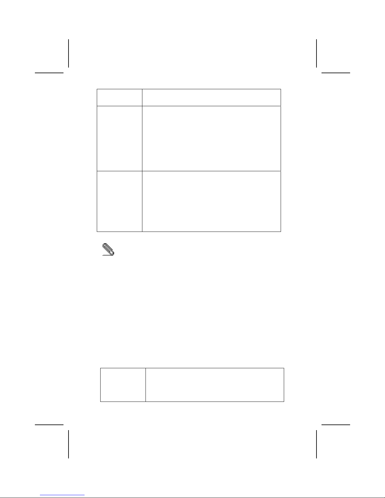
Processor The mainboard uses a micro PGA 478-pin socket that has the
following features:
• Supports 400/533 MHz frontside bus (FSB)
• Supports “Hyper-Threading” technology CPU
• Accommodates Pentium 4 processors at 1.5G/1.6G/1.7G…
3.06G and above
“Hyper-Threading” technology enables the operating system
into thinking it’s hooked up to two processors, allowing two
threads to be run in parallel, both on separate ‘logical’
processors within the same physical processor.
Chipset The SiS650GL/SiS651 Northbridge and SiS962/SiS962L
Southbridge chipsets are based on an innovative and scalable
architecture with proven reliability and performance.
• Support Intel Pentium 4 series CPU with data transfer
rate of 533/400MHz
• Support 12 outstanding transactions
• Supports DDR333/DDR266/200 SDRAM
• AGP v2.0 Compliant
• Supports Graphic Window Size from 4MBytes to
256Mbytes
• Perform 533MB/s bandwidth in 66MHz x 4 mode
• Built-in a high quality 3D engine
• PCI 2.2 specification compliance
• Supports PIO mode 0,1,2,3,4 and Multiword DMA mode
0,1,2
• Supports Ultra DMA 33/66/100/133
• Three independent OHCI USB 1.1 host controllers and
one EHCI USB 2.0 host controller, support up to six ports
• Compliant with IEEE 1394-1995 and 1394a-2000
• System wake-up events include: Power button, keyboard
password/hot key, RTC alarm, Modem ring-in, LAN, AC
97 wake-up, USB wake up and 1394 wake up
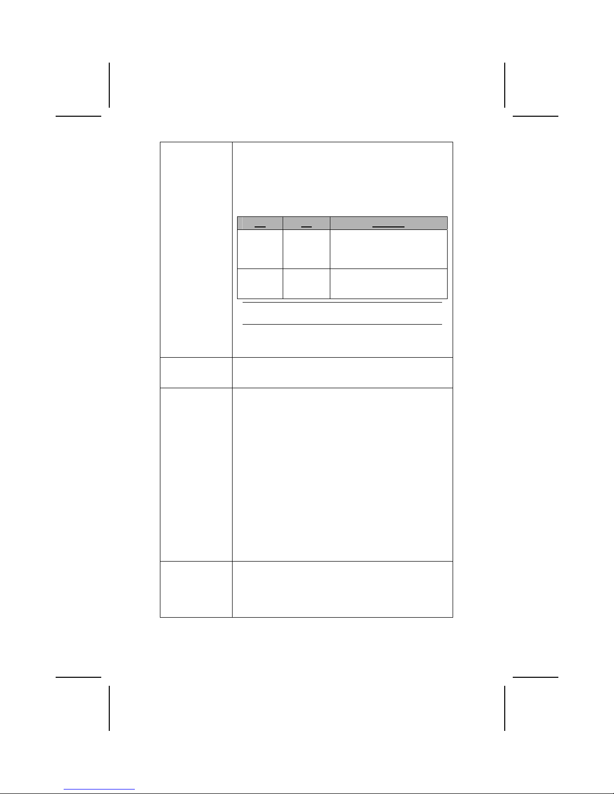
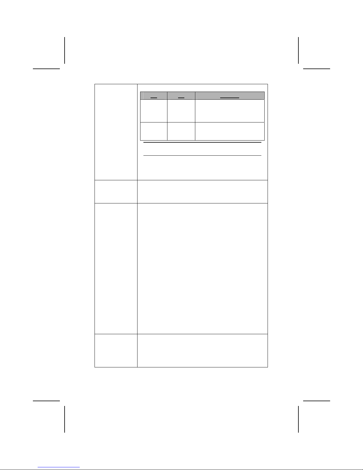
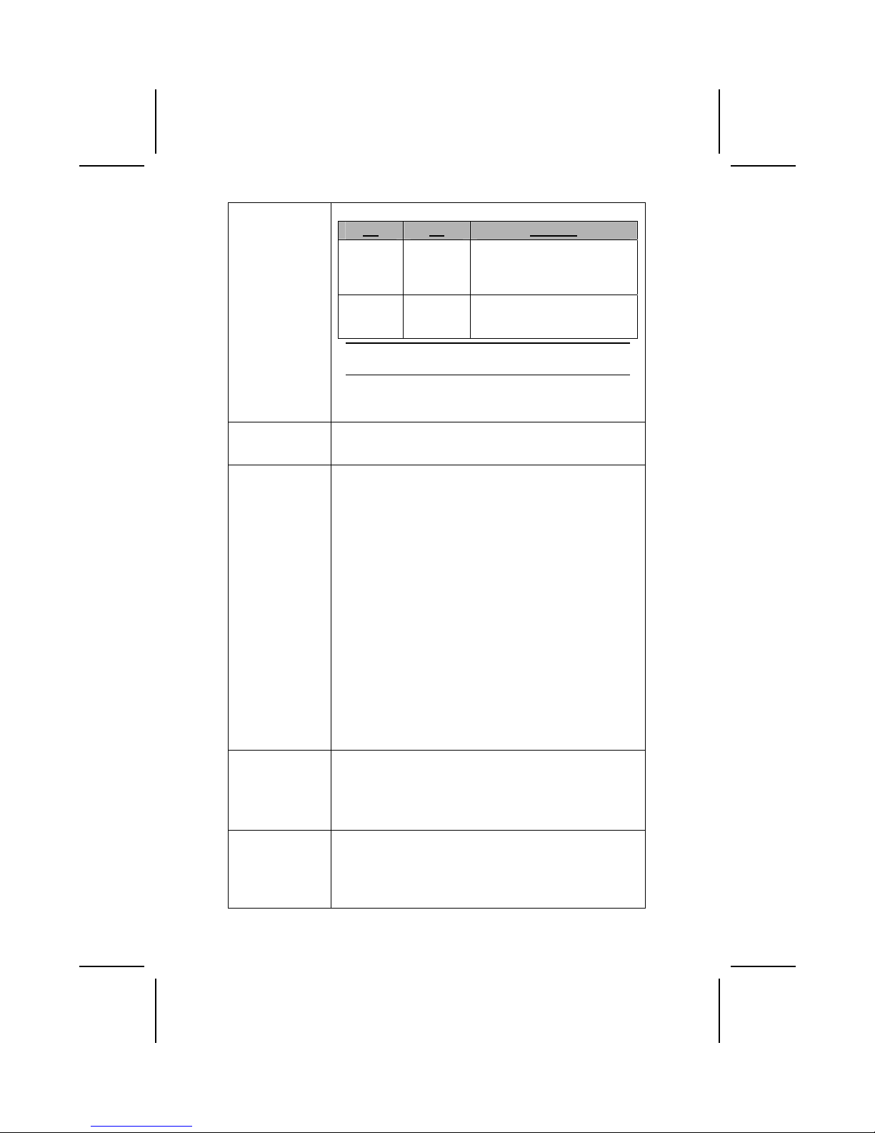
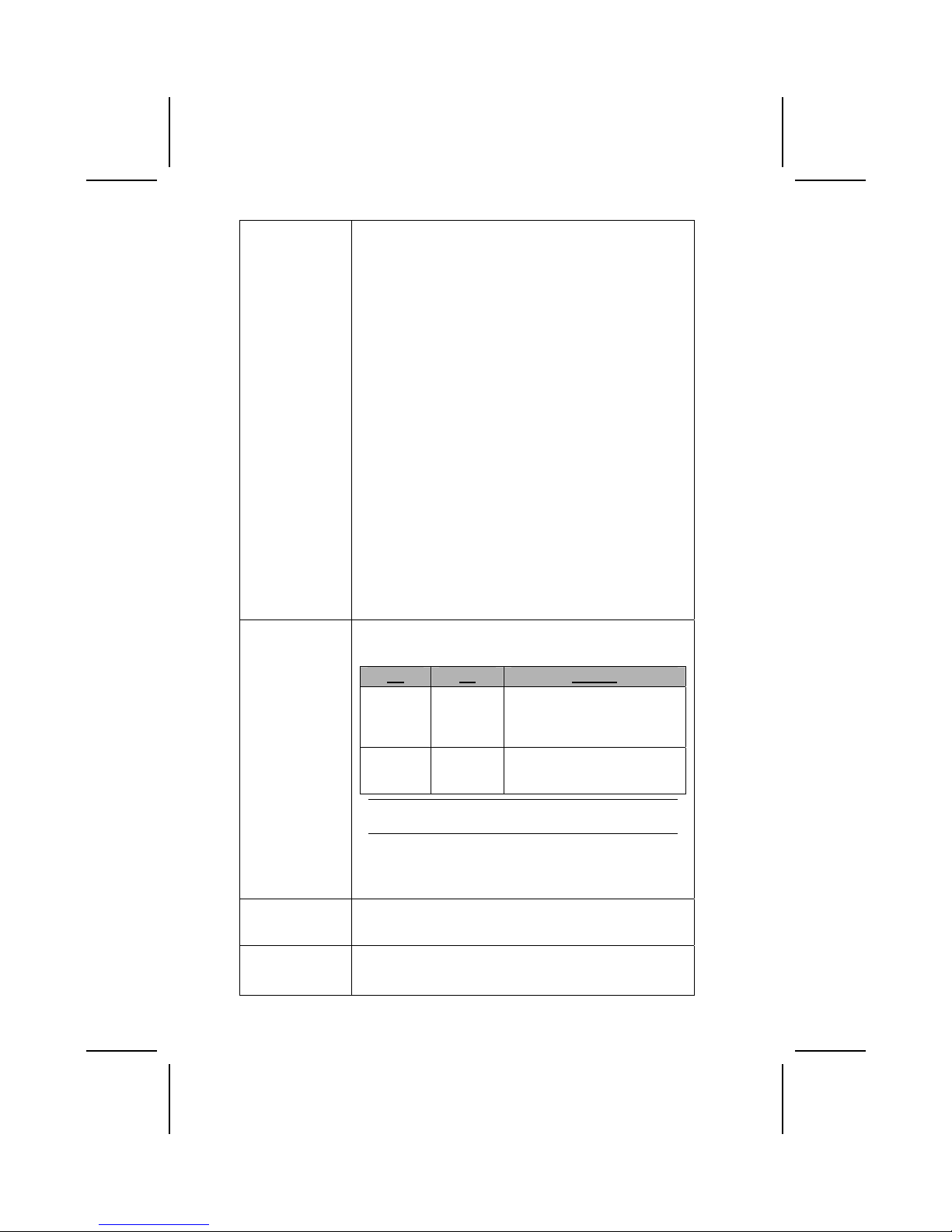
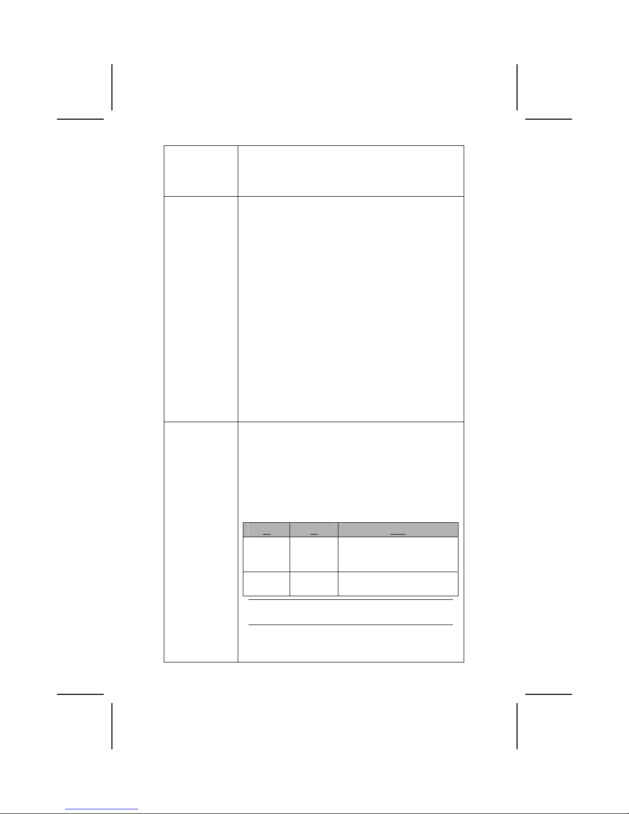
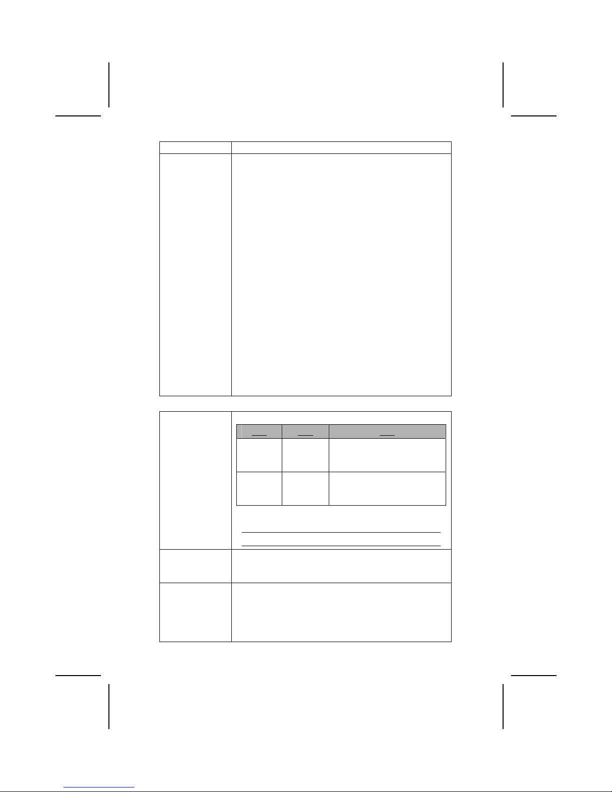
The mainboard may support either of the Northbridge and
Southbridge chipset mentioned above. Refer below for the
combination and respective details:
NB SB Function
SiS650GL
SiS962/
SiS962L
Support 400/533 (enhanced)
MHz FSB and DDR333; do not
support Hyper-Threading
technology.
SiS651
SiS962/
962L
Support 533 MHz FSB,
DDR333 and Hyper-Threading
technology.
Note: The SiS962L Southbridge chipset does not
support the IEEE1394A function.
Additional key features of the mainboard include support for
six USB ports, an AC’ 97 link for audio and modem, hardware
monitoring, and ACPI/OnNow power management.
2
Page 35

Memory The mainboard supports DDR 266/333 SDRAM. It
accommodates two unbuffered 2.5V 184-pin slots. Each slot
supports up to 1 GB with a total maximum capacity of 2 GB.
USB The USB 2.0 Controller is compliant with Universal Serial Bus
Specification Revision 2.0.
The USB 2.0 supports data transfer rates up to 480MB/sec for
high-speed devices and specifies a microframe that will be
1/8
th
of a 1msec frame. This allows the USB 2.0 devices to
have small buffers even at high data rates.
The USB 1.1 connectors and other full speed cables can
support the higher speed of USB 2.0 without any changes.
The chipset has the following advanced USB features:
• Compliant with Enhanced Host Controller Interface
(EHCI) Specification Revision 0.95 and Universal Host
Controller Interface (UHCI) Specification Revision 1.1
• PCI multi-function device consists of two UHCI Host
Controllers for full/low-speed signaling and one EHCI Host
Controller core for high-speed signaling
• Supports PCI-Bus Power Management Interface
Specification release 1.1
• Legacy support for all downstream facing ports
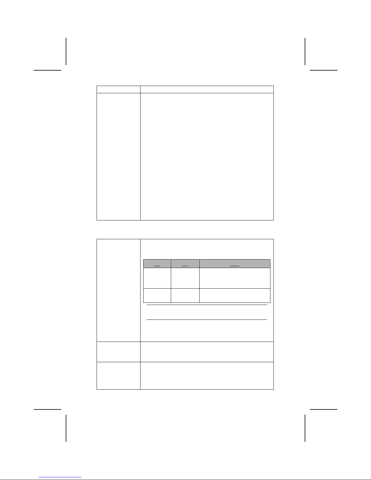
Graphics The mainboard includes an AGP slot that provides four times
the bandwidth of the original AGP specification. AGP
technology provides a direct connection between the graphics
sub-system and the processor so that the graphics do not
have to compete for processor time with other devices on the
PCI bus.
AC’ 97 Audio
Codec
The AC’ 97 Audio codec is compliant with the AC 97 2.2
specification that meets the PC2001 requirements and
supports S/PDIF In/Out. It also has a built-in buffer and internal
PLL. Features include support for analog switch for rear-out
(share), the line-in jack (share), center/bass (share), and MIC
jack to output 6 channels audio.
Note: Optional 4-channel audio controller.
Onboard LAN
(optional)
The Realtek RTL8100B LAN chip is incorporated in the chipset
providing the mainboard with integrated Ethernet PCI LAN
capabilities.
Expansion
Options
The mainboard comes with the following expansion options:
• Three 32-bit PCI slots
• One AGP slot
• A Communications and Network Riser (CNR) slot (AC97
interface only)
• Two IDE channels and a floppy disk drive interface
The mainboard supports Ultra DMA bus mastering with
transfer rates of 33/66/100/133 MB/sec.
IEEE 1394A
Controller
Interface
(optional)
• Fully support provisions of IEEE1394-1995 for High-
Performance Serial Bus and the P1394a draft 2.0
standard
• Provides one compliant cable port at 100Mbits/s,
200Mbits/s, and 400Mbits/s
• Supports arbitrated short bus reset to improve utilization
of the bus
3
Page 36

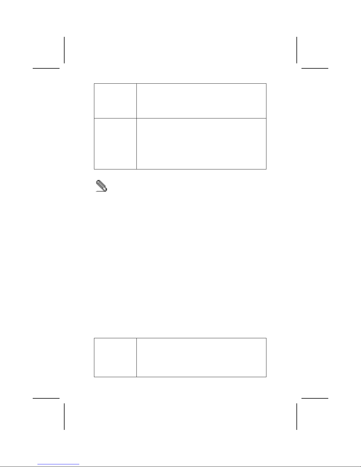
• Data interface to link-layer controller provided through
2/4/8 parallel lines at 50Mbits/s
• Support power-down feature to conserve energy in
battery powered applications
Integrated I/O The mainboard has a full set of I/O ports and connectors:
• Two PS/2 ports for mouse and keyboard
• One serial port
• One VGA port
• One parallel port
• Four USB ports
• One LAN port
• One 1394a port
• Audio jacks for microphone, line-in and line-out
BIOS
Firmware
This mainboard uses Award BIOS that enables users to
configure many system features including the following:
• Power management
• Wake-up alarms
• CPU parameters
• CPU and memory timing
The firmware can also be used to set parameters for different
processor clock speeds.
Some hardware specifications and software items are subject to change
without prior notice.
CChhoooossiinngg aa CCoommppuutteerr CCaassee
There are many types of computer cases on the market. The mainboard
complies with the specifications for the Micro ATX system case. Some
features on the mainboard are implemented by cabling connectors on the
mainboard to indicators and switches on the system case. Ensure that your
case supports all the features required. The mainboard can support one or
two floppy diskette drives and four enhanced IDE drives. Ensure that your
case has sufficient power and space for all the drives that you intend to install.
Most cases have a choice of I/O templates in the rear panel. Make sure that
the I/O template in the case matches the I/O ports installed on the rear edge
of the mainboard.
This mainboard has a Micro ATX form factor of 244 x 220 mm. Choose a case
that accommodates this form factor.
4
Page 37

MMaaiinnbbooaarrdd CCoommppoonneennttss
5
Page 38

Table of Mainboard Components
Label Component
1394A_J1 IEEE 1394A header
AGP1 Accelerated Graphics Port
ATX1 Power connector
ATX2 Standard 20-pin ATX power connector
AUDIO1 Front audio connector
BAT1 Three volt realtime clock battery
CASFAN1 Case fan connector 1
CDIN1 Primary CD-in connector
CDIN2 Secondary CD-in connector
CNR1 Communications Networking Riser slot
COM2 Onboard serial port header COM2
CPU SOCKET Micro PGA 478-pin socket for Pentium 4 CPUs
CPUFAN1 Cooling fan for CPU
DIMM1 ~ DIMM2 Two 184-pin DDR SDRAM
FDD1 Floppy disk drive connector
IDE 1 Primary IDE channel
IDE 2 Secondary IDE channel
IR1 Infrared cable header
JP1 Clear CMOS jumper
JP2 BIOS protection jumper
LED11 Memory module LED
PANEL1 Connector for case front panel switches and LED indicators
PCI1 ~ PCI3 Three 32-bit add-on card slots
PWRFAN1 Case fan connector 2
SJ1 Single color LED header
SPDIF1 SPDIF out header
SPEAKER1 Speaker connector
USB2 Front panel USB headers
USB3 USB Card Reader header
WOL1 Wake On LAN wakeup connector
WOM1 Wake On Modem wakeup connector
This concludes Chapter 1. The next chapter explains how to install the
mainboard.
6
1
The red indicator LED1 turns on if your system is still powered, at which
time memory modules cannot be installed or uninstalled.
Page 39

CChhaapptteerr 22
Installing the Mainboard
SSaaffeettyy PPrreeccaauuttiioonnss
Follow these safety precautions when installing the mainboard:
• Wear a grounding strap attached to a grounded device to avoid
damage from static electricity.
• Discharge static electricity by touching the metal case of a safely
grounded object before working on the mainboard.
• Leave components in the static-proof bags they came in.
• Hold all circuit boards by the edges. Do not bend circuit boards.
QQuuiicckk GGuuiiddee
This Quick Guide suggests the steps you can take to assemble your system
with the mainboards.
The following table provides a reference for installing specific components:
Locating Mainboard Components Go to page 5
Installing the Mainboard in a Case Go to page 8
Setting Jumpers Go to page 8
Installing Case Components Go to page 10
Installing the CPU Go to page 13
Installing Memory Go to page 16
Installing a HDD and CD-ROM Drive Go to page 17
Installing a FDD Go to page 19
Installing Add-on Cards Go to page 19
Connecting Options Go to page 21
Connecting Peripheral (I/O) Devices Go to page 24
Page 40

IInnssttaalllliinngg tthhee MMaaiinnbbooaarrdd iinn aa CCaassee
Refer to the following illustration and instructions for installing the mainboard
in a case:
This illustration shows an
example of a mainboard being
installed in a tower-type case:
Note: Do not overtighten
the screws as this
can stress the
mainboard.
Most system cases have
mounting brackets installed in
the case, which correspond to
the holes in the mainboard.
Place the mainboard over the
mounting brackets and secure
the mainboard onto the
mounting brackets with
screws.
2. Secure the mainboard with
screws where appropriate.
1. Place the mainboard
over the mounting brackets.
Ensure that your case has an I/O template that supports the I/O ports and
expansion slots on your mainboard.
CChheecckkiinngg JJuummppeerr SSeettttiinnggss
This section explains how to set jumpers for correct configuration of the
mainboard.
Setting Jumpers
Use the mainboard jumpers to set system configuration options. Jumpers with
more than one pin are numbered. When setting the jumpers, ensure that the
jumper caps are placed on the correct pins.
The illustrations below show a 2-pin jumper.
When the jumper cap is placed on both pins,
the jumper is SHORT. If you remove the
jumper cap, or place the jumper cap on just
one pin, the jumper is OPEN.
This illustration shows a 3-pin
jumper. Pins 1 and 2 are SHORT.
Short Open
1
2
3
8
Page 41

Checking Jumper Settings
The following illustration shows the location of the mainboard jumpers. Pin 1 is
labeled.
Jumper Settings
Jumper Type Description Setting (default)
JP1 3-pin Clear CMOS 1-2: Normal
2-3: Clear
JP1
1
JP2 3-pin BIOS protect 1-2: Write Enabled
2-3: Write Disabled
JP2
1
Jumper 1 – Use this jumper to clear the contents of the CMOS memory.
You may need to clear the CMOS memory if the settings in
the Setup Utility are incorrect and prevent your mainboard
from operating. To clear the CMOS memory, disconnect all
the power cables from the mainboard and then move the
jumper cap into the CLEAR setting for a few seconds.
Jumper 2 – Enables you to prevent the BIOS from being updated
(flashed). Set the jumper to disabled if you are going to
update your BIOS. After updating the BIOS, return it to the
default setting (Enabled).
9
Page 42

CCoonnnneeccttiinngg CCaassee CCoommppoonneennttss
After you have installed the mainboard into a case, you can begin connecting
the mainboard components. Refer to the following:
1. Connect the Pentium
4 processor auxiliary
case power supply
connector to ATX1.
2. Connect the standard
power supply
connector to ATX2.
3. Connect the CPU
cooling fan cable to
CPUFAN1.
4. Connect the auxiliary
power supply cooling
fan connector to
PWRFAN1.
5. Connect the case
cooling fan connector
to CASFAN1.
6. Connect the case
speaker cable to
SPEAKER1.
7. Connect the case
LED cable to SJ1.
8. Connect the case switches and indicator to PANEL1.
ATX2: ATX 20-pin Power Connector
Pin Signal Name Pin Signal Name
1 +3.3V 11 +3.3V
2 +3.3V 12 -12V
3 Ground 13 Ground
4 +5V 14 PS ON#
5 Ground 15 Ground
6 +5V 16 Ground
7 Ground 17 Ground
8 PWRGD 18 +5V
9 +5VSB 19 +5V
10 +12V 20 +5V
ATX1: ATX 12V Power Connector
Pin Signal Name
1 +12V
2 +12V
3 Ground
4 Ground
10
Page 43

CPUFAN1/CASFAN1/PWRFAN1: FAN Power Connectors
Pin Signal Name Function
1 GND System Ground
2 +12V Power +12V
3 Sense Sensor
SPEAKER1: Internal speaker
Pin Signal Name
1 Signal
2 Key
3 Ground
4 VCC
SJ1: Single color LED header
Pin Signal Name Function
1 ACPI LED MSG LED (-) green
2 ACPI LED MSG LED (-) green
3 SB5V Power LED (+)
ACPI LED function:
S0 S1 S3 S4/S5
SJ1
1
Light Blinking Blinking Dark
11
Page 44

Front Panel Connector
The front panel connector (PANEL1) provides a standard set of switch and
LED connectors commonly found on ATX or micro-ATX cases. Refer to the
table below for information:
PANEL1
Pin Function Pin Function
1
Hard disk LED
(positive)
2
MSG LED [dual color
or single color (+)]
3
Hard disk active LED
(negative)
4
MSG LED [dual color
or single color (-)]
5
Reset Switch
6
Power Switch
7
Reset Switch
8
Power Switch
9
Reserved
10
No pin
Hard Drive Activity LED
Connecting pins 1 and 3 to a front panel mounted LED provides visual
indication that data is being read from or written to the hard drive. For the LED
to function properly, an IDE drive should be connected to the onboard IDE
interface. The LED will also show activity for devices connected to the SCSI
(hard drive activity LED) connector.
Power / Sleep / Message Waiting LED
Connecting pins 2 and 4 to a single- or dual-color, front panel mounted LED
provides power on/off, sleep, and message waiting indication.
Reset Switch
Supporting the reset function requires connecting pins 5 and 7 to a
momentary-contact switch that is normally open. When the switch is closed,
the board resets and runs POST.
Power Switch
Supporting the power on/off function requires connecting pins 6 and 8 to a
momentary-contact switch that is normally open. The switch should maintain
contact for at least 50 ms to signal the power supply to switch on or off. The
time requirement is due to internal debounce circuitry. After receiving a power
on/off signal, at least two seconds elapses before the power supply
recognizes another on/off signal.
12
Page 45

IInnssttaalllliinngg HHaarrddwwaarree
Installing the Processor
Caution: When installing a CPU heatsink and cooling fan make sure that
you DO NOT scratch the mainboard or any of the surface-mount resistors
with the clip of the cooling fan. If the clip of the cooling fan scrapes
across the mainboard, you may cause serious damage to the mainboard
or its components.
On most mainboards, there are small surface-mount resistors near the
processor socket, which may be damaged if the cooling fan is carelessly
installed.
Avoid using cooling fans with sharp edges on the fan casing and the
clips. Also, install the cooling fan in a well-lit work area so that you can
clearly see the mainboard and processor socket.
Before installing the Processor
This mainboard automatically determines the CPU clock frequency and
system bus frequency for the processor. You may be able to change these
settings by making changes to jumpers on the mainboard, or changing the
settings in the system Setup Utility. We strongly recommend that you do not
overclock processors or other components to run faster than their rated
speed.
Warning: Overclocking components can adversely affect the reliability of
the system and introduce errors into your system. Overclocking can
permanently damage the mainboard by generating excess heat in
components that are run beyond the rated limits.
This mainboard has a Socket 478 processor socket. When choosing a
processor, consider the performance requirements of the system.
Performance is based on the processor design, the clock speed and system
bus frequency of the processor, and the quantity of internal cache memory
and external cache memory.
13
Page 46

CPU Installation Procedure
The following illustration shows CPU installation components:
Note: The pin-1 corner is marked with an arrow
Follow these instructions to install the Retention Module and CPU:
1. Remove the existing retention module (if applicable).
2. Position the backplate
against the underside of
the mainboard, secure
the 4 screws firmly on
the retention module.
Note: Do not over tighten
the screws.
3. Install your CPU. Pull up
the lever away from the
socket and lift up to 90degree angle.
14
Page 47

4. Locate the CPU cut
edge (the corner with the
pinhole noticeably
missing). Align and
insert the CPU correctly.
5. Press the lever down.
6. Apply thermal grease on top of the CPU.
7. Put the CPU Fan down
on the retention module
and snap the four
retention legs of the
cooling fan into place.
8. Flip the levers over to lock the heat sink in place.
9. Connect the CPU
Cooling Fan power cable
to the CPUFAN1
connector. This
completes the
installation.
Notes:
•
To achieve better airflow rates and heat dissipation, we suggest that
you use a high quality fan with 4800 rpm at least.
• CPU fan and heatsink installation procedures may vary with the type of
CPU fan/heatsink supplied. The form and size of fan/heatsink may also
vary.
15
Page 48

Installing Memory Modules
This mainboard accommodates 184-pin 2.5V unbuffered Double Data Rate
(DDR) SDRAM memory modules. The memory chips must be standard or
registered SDRAM (Synchronous Dynamic Random Access Memory). The
memory bus runs at 166 MHz.
Note: SDRAM provides 800 MBps or 1 GBps data transfer depending on
whether the bus is 100MHz or 133MHz. Double Data Rate SDRAM
(DDR SDRAM) doubles the rate to 1.6 GBps and 2.1 GBps. DDR
SDRAM uses additional power and ground lines and requires 184-pin
DIMM modules rather than the 168-pin DIMMs used by SDRAM.
The mainboard accommodates two memory modules. You must install at least
one module in any of the two slots. Each module can be installed with 32 MB
to 1 GB of memory; total memory capacity is 2 GB.
Do not remove any memory module from its antistatic packaging until
you are ready to install it on the mainboard. Handle the modules only by
their edges. Do not touch the components or metal parts. Always wear
a grounding strap when you handle the modules.
Installation Procedure
Refer to the following to install the memory modules.
1. This mainboard supports unbuffered DDR SDRAM only. Do not attempt to
insert any other type of DDR SDRAM into the slots.
2. Push the latches on each side of the DIMM slot down.
3. Align the memory module with
the slot. The DIMM slots are
keyed with notches and the
DIMMs are keyed with cutouts
so that they can only be
installed correctly.
4. Check that the cutouts on the
DIMM module edge connector
match the notches in the
DIMM slot.
16
Page 49

5. Install the DIMM module into
the slot and press it firmly
down until it seats correctly.
The slot latches are levered
upwards and latch on to the
edges of the DIMM.
6. Install any remaining DIMM modules.
Installing a Hard Disk Drive/CD-ROM
This section describes how to install IDE devices such as a hard disk drive
and a CD-ROM drive.
About IDE Devices
Your mainboard has a primary and secondary IDE channel interface (IDE1 and
IDE2). An IDE ribbon cable supporting two IDE devices is bundled with the
mainboard.
If you want to install more than two IDE devices, get a second IDE cable and
you can add two more devices to the secondary IDE channel.
IDE devices have jumpers or switches that are used to set the IDE device as
MASTER or SLAVE. Refer to the IDE device user’s manual. When installing two
IDE devices on one cable, ensure that one device is set to MASTER and the
other device is set to SLAVE. The documentation of your IDE device explains
how to do this.
About UltraDMA
This mainboard supports UltraDMA 66/100/133. UDMA is a technology that
accelerates the performance of devices in the IDE channel. To maximize
performance, install IDE devices that support UDMA and use 80-pin IDE
cables that support UDMA 66/100/133.
17
Page 50

Installing a Hard Disk Drive
1. Install the hard disk drive into the drive cage in your system case.
2. Plug the IDE cable into IDE1
(A):
Note: Ribbon cable connectors
are usually keyed so that they can
only be installed correctly on the
device connector. If the connector
is not keyed, make sure that you
match the pin-1 side of the cable
connector with the pin-1 side of the
device connector. Each connector
has the pin-1 side clearly marked.
The pin-1 side of each ribbon
cable is always marked with a
colored stripe on the cable.
3. Plug an IDE cable connector into the hard disk drive IDE connector (B). It
doesn't matter which connector on the cable you use.
4. Plug a power cable from the case power supply into the power connector on
the hard disk drive (C).
When you first start up your system, the BIOS should automatically detect
your hard disk drive. If it doesn’t, enter the Setup Utility and use the IDE Hard
Disk Auto Detect feature to configure the hard disk drive that you have
installed. See IDE HDD Auto-Detection on page 31 for more information.
Installing a CD-ROM/DVD Drive
1. Install the CD-ROM/DVD drive into the drive cage in your system case.
2. Plug the IDE cable into IDE1
(A). If you have already installed
an HDD, use the other
connector on the IDE cable.
Note: Ribbon cable connectors are
usually keyed so that they can only
be installed correctly on the device
connector. If the connector is not
keyed, make sure that you match the
pin-1 side of the cable connector with
the pin-1 side of the device
connector. Each connector has the
pin-1 side clearly marked. The pin-1
side of each ribbon cable is always
marked with a colored stripe on the
cable.
3. Plug an IDE cable connector into the CD-ROM/DVD drive IDE connector (B). It
doesn't matter which connector on the cable you use.
4. Plug a power cable from the case power supply into the power connector on
the CD-ROM/DVD drive (C).
5. Use the audio cable provided with the CD-ROM/DVD drive to connect to the
mainboard CD-in connector CDIN1 or CDIN2 (D).
When you first start up your system, the BIOS should automatically detect
your CD-ROM/DVD drive. If it doesn’t, enter the Setup Utility and configure
the CD-ROM/DVD drive that you have installed. See IDE Primary/Secondary
18
Page 51

Master/Slave (Auto) on page 31 for more information.
Installing a Floppy Diskette Drive
The mainboard has a floppy diskette drive (FDD) interface and ships with a
diskette drive ribbon cable that supports one or two floppy diskette drives. You
can install a 5.25-inch drive and a 3.5-inch drive with various capacities. The
floppy diskette drive cable has one type of connector for a 5.25-inch drive and
another type of connector for a 3.5-inch drive.
1. Install the FDD into the drive cage in your system case.
2. Plug the FDD cable into FDD1
(A):
Note: Ribbon cable connectors are
usually keyed so that they can only
be installed correctly on the device
connector. If the connector is not
keyed, make sure that you match the
pin-1 side of the cable connector with
the pin-1 side of the device
connector. Each connector has the
pin-1 side clearly marked. The pin-1
side of each ribbon cable is always
marked with a colored stripe on the
cable.
3. Plug the correct connector on the FDD cable for the 5.25-inch or 3.5-inch drive
into the FDD connector (B).
4. Plug a power cable from the case power supply into the power connector on
the FDD (C).
When you first start up your system, go immediately to the Setup Utility to
configure the floppy diskette drives that you have installed. See Standard
CMOS Features on page 30 for more information.
Installing Add-on Cards
The slots in this mainboard are designed to hold expansion cards and connect
them to the system bus. Expansion slots are a means of adding or enhancing
the mainboard’s features and capabilities. With these efficient facilities, you
can increase the mainboard’s capabilities by adding hardware which performs
tasks that are not part of the basic system.
19
Page 52

PCI Slots PCI slots are used to install expansion cards that have the 32-bit
PCI interface.
AGP Slot The AGP slot is used to install a graphics adapter that supports the
4xAGP specification and has a 4xAGP edge connector.
Note: The layout is for reference only. The AGP slot may
be different from your mainboard. Please refer to
actual shipment.
CNR Slot This slot is used to insert CNR cards with Modem and Audio
functionality.
Note: Before installing an add-on card, check the documentation for the card
carefully. If the card is not Plug and Play, you may have to manually
configure the card before installation.
Follow these instructions to install an add-on card:
1. Remove a blanking plate from the system case corresponding to the slot you
are going to use.
2. Install the edge connector of the
add-on card into the expansion
slot. Ensure that the edge
connector is correctly seated in
the slot.
3. Secure the metal bracket of the card to the system case with a screw.
Note: For some add-on cards, for example graphics adapters and network adapters,
you have to install drivers and software before you can begin using the add-on
card.
20
Page 53

Connecting Optional Devices
Refer to the following for information on connecting the mainboard’s optional
devices:
AUDIO1: Front Panel Audio header
This header allows the user to install auxiliary front-oriented microphone and
line-out ports for easier access.
Pin Signal Name Function
1 AUD_MIC Front Panel Microphone input signal
2 AUD_GND Ground used by Analog Audio Circuits
3 AUD_MIC_BIAS Microphone Power
4 AUD_VCC Filtered +5 V used by Analog Audio Circuits
5 AUD_FPOUT_R Right Channel Audio signal to Front Panel
6 AUD_RET_R Right Channel Audio signal to Return from
Front Panel
7 HP_ON Reserved for future use to control
Headphone Amplifier
8 KEY No Pin
9 AUD_FPOUT_L Left Channel Audio signal to Front Panel
10 AUD_RET_L Left Channel Audio signal Return from
Front Panel
21
Page 54

USB2: Front panel USB ports
The mainboard has two USB ports installed on the rear edge I/O port array.
Additionally, some computer cases have USB ports at the front of the case. If
you have this kind of case, use auxiliary USB connector USB2 to connect the
front-mounted ports to the mainboard.
Pin Signal Name Function
1 VREG_FP_USBPWR0 Front Panel USB Power
2 VREG_FP_USBPWR0 Front Panel USB Power
3 USB_FP_P0- USB Port 0 Negative Signal
4 USB_FP_P1- USB Port 1 Negative Signal
5 USB_FP_P0+ USB Port 0 Positive Signal
6 USB_FP_P1+ USB Port 1 Positive Signal
7 GND Ground
8 GND Ground
9 KEY No pin
10 USB_FP_OC0 Overcurrent signal
Note: Please make sure that the USB cable has the same pin assignment as
indicated above. A different pin assignment may cause damage or system
hang-up.
WOL1: Wake On LAN
If you have installed a LAN card, use the cable provided with the card to plug
into the mainboard WOL1 connector. This enables the Wake On LAN (WOL)
feature. When your system is in a power-saving mode, any LAN signal
automatically resumes the system. You must enable this item using the Power
Management page of the Setup Utility.
Pin Signal Name Function
1 5VSB +5V stand by power
2 GND Ground
3 Ring# Wake up signal (high active)
WOM1: Wake On Modem
If you have installed a modem, use the cable provided with the modem to plug
into the mainboard WOM1 connector. This enables the Wake On Modem
(WOM1 feature. When your system is in a power-saving mode, any modem
signal automatically resumes the system. You must enable this item using the
Power Management page of the Setup Utility. See Chapter 3 for more
information.
Pin Signal Name Function
1 5VSB +5V stand by power
2 GND Ground
3 Ring# Wake up signal (low active)
22
Page 55

IR1: Serial infrared port
The mainboard supports an Infrared (IR) data port. Infrared ports allow the
wireless exchange of information between your computer and similarly
equipped devices such as printers, laptops, Personal Digital Assistants
(PDAs), and other computers.
Pin Signal Name Function
1 Not assigned Not assigned
2 KEY No pin
3 +5V IR Power
4 GND Ground
5 IRTX IrDA serial output
6 IRRX IrDA serial input
SPDIF1: SPDIF out header
This is an optional header that provides an S/PDIF (Sony/Philips Digital
Interface) output to digital multimedia device through optical fiber or coaxial
connector.
Pin Signal Name
1 SPDIF Out
2 VCC
3 KEY
4 GND
COM2: Onboard serial port connector
Connect a serial port extension bracket to this header to add a second serial
port to your system.
Pin Signal Name Function
1 NDCDB Data carry detect
2 NSINB Serial Data In
3 NSOUTB Serial Date Out
4 NDTRB Data terminal ready
5 GND Ground
6 NDSRB Date set ready
7 NRTSB Request to send
8 NCTSB Clear to send
9 NRIB Ring Indicator
10 Key Key
23
Page 56

1394A_J1: IEEE 1394A header
Use this header to connect to any IEEE 1394A interface.
Pin Signal Name Pin Signal Name
1 Cable-power 5 TPA2 GND 6 TPA+
3 TPB- 7 Chassis GND
4 TPB+ 8 NC
USB3: USB Card Reader connector
This connector is for connecting internal USB card reader. You can use a card
reader to read or transfer files and digital images to your computer.
Pin Signal Name Function
1 USBVCC2 +5V dual
2 USB2- Data signal port 23 USB2+ Data signal port 2+
4 GND Ground
5 Key No pin
Note: The USB3 is shared with one of the USB ports of the I/O back panel. The
USB port is located beside the serial port connectors. See “Connecting I/O
Devices” for more information.
Please check the pin assignment of the cable and the USB header on
the mainboard. Make sure the pin assignment will match before
plugging in. Any incorrect usage may cause unexpected damage to the
system.
24
Page 57

CCoonnnneeccttiinngg II//OO DDeevviicceess
The backplane of the mainboard has the following I/O ports:
PS/2 Mouse Use the upper PS/2 port to connect a PS/2
pointing device.
PS/2 Keyboard Use the lower PS/2 port to connect a PS/2
keyboard.
LPT1 Use LPT1 to connect printers or other parallel
communications devices.
COM1 Use the COM ports to connect serial devices
such as mice or fax/modems. COM1 is identified
by the system as COM1/3.
VGA Port Connect your monitor to the VGA port.
1394a Port Use the 1394a port to connect any Firewire
device.
Audio Ports Use the three audio ports to connect audio
devices. The first jack is for stereo line-in signal.
The second jack is for stereo line-out signal. The
third jack is for microphone.
LAN Port Connect an RJ-45 jack to the LAN port to
connect your computer to the Network.
USB Ports Use the USB ports to connect USB devices.
Note: The USB port located below the
1394a port is shared with the USB3
connector.
25
Page 58

External Connector Color Coding
Many connectors now use standard colors as shown in the table below.
Connector Color
Audio line-in Light blue
Audio line-out Lime
Digital monitor/flat panel White
IEEE 1394 Grey
Microphone Pink
MIDI/game Gold
Parallel Burgundy
PS/2-compatible keyboard Purple
PS/2-compatible mouse Green
Serial Teal or Turquoise
Speaker out/subwoofer Orange
Right-to-left speaker Brown
USB Black
Video out Yellow
SCSI, network, telephone, modem None
This concludes Chapter 2. The next chapter covers the BIOS.
26
Page 59

CChhaapptteerr 33
Using BIOS
AAbboouutt tthhee SSeettuupp UUttiilliittyy
The computer uses the latest Award BIOS with support for Windows Plug and
Play. The CMOS chip on the mainboard contains the ROM setup instructions
for configuring the mainboard BIOS.
The BIOS (Basic Input and Output System) Setup Utility displays the system's
configuration status and provides you with options to set system parameters.
The parameters are stored in battery-backed-up CMOS RAM that saves this
information when the power is turned off. When the system is turned back on,
the system is configured with the values you stored in CMOS.
The BIOS Setup Utility enables you to configure:
• Hard drives, diskette drives, and peripherals
• Video display type and display options
• Password protection from unauthorized use
• Power management features
The settings made in the Setup Utility affect how the computer performs.
Before using the Setup Utility, ensure that you understand the Setup Utility
options.
This chapter provides explanations for Setup Utility options.
The Standard Configuration
A standard configuration has already been set in the Setup Utility. However,
we recommend that you read this chapter in case you need to make any
changes in the future.
This Setup Utility should be used:
• when changing the system configuration
• when a configuration error is detected and you are prompted to
make changes to the Setup Utility
• when trying to resolve IRQ conflicts
• when making changes to the Power Management configuration
• when changing the password or making other changes to the
Security Setup
Page 60

Starting Setup
The BIOS is immediately activated when you first turn on the computer. The
BIOS reads system configuration in CMOS RAM and begins the process of
checking out the system and configuring it through the power-on self test
(POST).
When these preliminaries are finished, the BIOS seeks an operating system
on one of the data storage devices (hard drive, floppy drive, etc.). The BIOS
launches the operating system and hands control of system operations to it.
During POST, you can start the Setup program in one on two ways:
1. By pressing Del immediately after switching the system on, or
2. By pressing Del or pressing Ctrl+Alt+Esc when the following message
appears briefly at the bottom of the screen during POST:
TO ENTER SETUP BEFORE BOOT PRESS DEL KEY
If the message disappears before you respond and you still wish to enter Setup, restart
the system to try again by turning it OFF then ON or pressing the RESET button on the
system case. You may also restart by simultaneously pressing Ctrl+Alt+Del. If you do
not press the keys at the correct time and the system does not boot, an error message
appears and you are again asked to:
PRESS F1 TO CONTINUE, DEL TO ENTER SETUP
Phoenix – AwardBIOS CMOS Setup Utility
Standard CMOS Features
Advanced BIOS Features
Advanced Chipset Features
Integrated Peripherals
Power Management Setup
PnP/PCI Configurations
PC Health Status
Frequency/Voltage Control
Load Fail-Safe Defaults
Load Optimized Defaults
Set Password
Save & Exit Setup
Exit Without Saving
Esc : Quit ↑ ↓ → ← : Select Item
F10 : Save & Exit Setup
Time, Date, Hard Disk Type . . .
28
Page 61

BIOS Navigation Keys
The BIOS navigation keys are listed below:
Key Function
Esc Exits the current menu
←↑↓→
Scrolls through the items on a menu
+/–/PU/PD Modifies the selected field's values
F10 Saves the current configuration and exits setup
F1 Displays a screen that describes all key functions
F5 Loads previously saved values to CMOS
F6 Loads a minimum configuration for troubleshooting.
F7 Loads an optimum set of values for peak performance
Updating the BIOS
You can download and install updated BIOS for this mainboard from the
manufacturer's Web site. New BIOS provides support for new peripherals,
improvements in performance, or fixes for known bugs. Install new BIOS as
follows:
1. If your mainboard has a BIOS protection jumper, change the setting to
allow BIOS flashing.
2. If your mainboard has an item called Firmware Write Protect in Advanced
BIOS features, disable it. (Firmware Write Protect prevents BIOS from being
overwritten.)
3. Create a bootable system disk. (Refer to Windows online help for
information on creating a bootable system disk.)
4. Download the Flash Utility and new BIOS file from the manufacturer's
Web site. Copy these files to the system diskette you created in Step 3.
5. Turn off your computer and insert the system diskette in your computer's
diskette drive. (You might need to run the Setup Utility and change the boot
priority items on the Advanced BIOS Features Setup page, to force your
computer to boot from the floppy diskette drive first.)
6. At the A:\ prompt, type the Flash Utility program name and press
<Enter>. You see a screen similar to the following:
FLASH MEMORY WRITER V7.33
(C) Award Software 1999 All Rights Reserved
For (MAINBOARD NAME) DATE: 10/26/2000
Flash Type
File Name to Program :____________________
Error Message
7. Type the filename of the new BIOS in the “File Name to Program” text
box. Follow the onscreen directions to update the mainboard BIOS.
29
Page 62

8. When the installation is complete, remove the floppy diskette from the
diskette drive and restart your computer. If your mainboard has a Flash
BIOS jumper, reset the jumper to protect the newly installed BIOS from
being overwritten.
UUssiinngg BBIIOOSS
When you start the Setup Utility, the main menu appears. The main menu of
the Setup Utility displays a list of the options that are available. A highlight
indicates which option is currently selected. Use the cursor arrow keys to
move the highlight to other options. When an option is highlighted, execute
the option by pressing <Enter>.
Some options lead to pop-up dialog boxes that prompt you to verify that you
wish to execute that option. Other options lead to dialog boxes that prompt
you for information.
Some options (marked with a triangle
) lead to submenus that enable you
to change the values for the option. Use the cursor arrow keys to scroll
through the items in the submenu.
In this manual, default values are enclosed in parenthesis. Submenu items
are denoted by a triangle .
Standard CMOS Features
In the Standard CMOS menu you can set the system clock and calendar,
record disk drive parameters and the video subsystem type, and select the
type of errors that stop the BIOS POST.
Phoenix – AwardBIOS CMOS Setup Utility
Standard CMOS Features
Item Help
Date (mm:dd:yy) Tue, July 11 2001
Time (hh:mm:ss) 12 : 8 : 59
IDE Primary Master
IDE Primary Slave
IDE Secondary Master
IDE Secondary Slave
Drive A [1.44M, 3.5 in.]
Drive B [None]
Floppy 3 Mode Support [Disabled]
Video [EGA/VGA]
Halt On [All Errors]
Base Memory 640K
Extended Memory 31744K
Total Memory 32768K
Menu Level
Change the day, month,
year and century.
↑ ↓ → ← : Move Enter : Select +/-/PU/PD:Value: F10: Save ESC: Exit F1:General Help
F5:Previous Values F6:Fail-Safe Defaults F7:Optimized Defaults
Date and Time
The Date and Time items show the current date and time on the computer. If
you are running a Windows OS, these items are automatically updated
30
Page 63

whenever you make changes to the Windows Date and Time Properties utility.
IDE Devices (None)
Your computer has two IDE channels (Primary and Secondary) and each
channel can be installed with one or two devices (Master and Slave). Use
these items to configure each device on the IDE channel.
Press <Enter> to display the IDE submenu:
Phoenix – AwardBIOS CMOS Setup Utility
IDE Primary Master
Item Help
IDE HDD Auto-Detection [Press Enter]
IDE Primary Master [Auto]
Access Mode [Auto]
Capacity 0 MB
Cylinder 0
Head 0
Precomp 0
Landing Zone 0
Sector 0
Menu Level
To auto-detect the
HDD’s size, head . . . on
this channel
↑ ↓ → ← : Move Enter : Select +/-/PU/PD:Value: F10: Save ESC: Exit F1:General Help
F5:Previous Values F6:Fail-Safe Defaults F7:Optimized Defaults
IDE HDD Auto-Detection
Press <Enter> while this item is highlighted to prompt the Setup Utility to
automatically detect and configure an IDE device on the IDE channel.
Note: If you are setting up a new hard disk drive that supports LBA mode, more
than one line will appear in the parameter box. Choose the line that lists
LBA for an LBA drive.
IDE Primary/Secondary Master/Slave (Auto)
Leave this item at Auto to enable the system to automatically detect and configure
IDE devices on the channel. If it fails to find a device, change the value to Manual
and then manually configure the drive by entering the characteristics of the drive in
the items described below.
Refer to your drive's documentation or look on the drive casing if you need to
obtain this information. If no device is installed, change the value to None.
Note: Before attempting to configure a hard disk drive, ensure that you have the
configuration information supplied by the manufacturer of your hard
drive. Incorrect settings can result in your system not recognizing the
installed hard disk.
Access Mode
This item defines ways that can be used to access IDE hard disks such as
LBA (Large Block Addressing). Leave this value at Auto and the system will
automatically decide the fastest way to access the hard disk drive.
Press <Esc> to return to the Standard CMOS Setup screen.
31
Page 64

Drive A/Drive B (1.44M, 3.5 in.)
These items define the characteristics of any diskette drive attached to the
system. You can connect one or two diskette drives.
Floppy 3 Mode Support (Disabled)
Floppy 3 mode refers to a 3.5-inch diskette with a capacity of 1.2 MB. Floppy
3 mode is sometimes used in Japan.
Video (EGA/VGA)
This item defines the video mode of the system. This mainboard has a built-in
VGA graphics system; you must leave this item at the default value.
Halt On (All Errors)
This item defines the operation of the system POST (Power On Self Test)
routine. You can use this item to select which types of errors in the POST are
sufficient to halt the system.
Base Memory, Extended Memory, and Total Memory
These items are automatically detected by the system at start up time. These
are display-only fields. You cannot make changes to these fields.
Advanced BIOS Setup
This screen contains industry-standard options additional to the core PC AT
BIOS.
Phoenix – AwardBIOS CMOS Setup Utility
Advanced BIOS Setup
Item Help
Virus Warning [Disabled]
CPU L1 & L2 Cache [Enabled]
Hyper-Threading Technology [Enabled]
Quick Power On Self Test [Enabled]
First Boot Device [Floppy]
Second Boot Device [HDD-0]
Third Boot Device [CDROM]
Boot Other Device [Enabled]
Swap Floppy Drive [Disabled]
Boot Up Floppy Seek [Disabled]
Boot Up NumLock Status [On]
Gate A20 Option [Fast]
ATA 66/100 Cable MSG Enabled]
Typematic Rate Setting [Disabled]
x Typematic Rate (Chars/Sec) 6
x Typematic Delay (Msec) 250
Security Option [Setup]
APIC Mode [Enabled]
OS Select For DRAM > 64MB [Non-OS2]
HDD S.M.A.R.T Capability [Disabled]
Menu Level
Allows you to choose
the VIRUS warning
feature for IDE Hard
Disk boot sector
protection. If this
function is enabled
and someone attempts
to write data into this
area, BIOS will show a
warning message on
screen and alarm beep
↑ ↓ → ← : Move Enter : Select +/-/PU/PD:Value: F10: Save ESC: Exit F1:General Help
F5:Previous Values F6:Fail-Safe Defaults F7:Optimized Defaults
32
Page 65

Virus Warning (Disabled)
When enabled, this item provides protection against viruses that try to write to
the boot sector and partition table of your hard disk drive. You need to disable
this item when installing an operating system. We recommend that you enable
this item as soon as you have installed an operating system.
Note: For complete protection against viruses, install virus software in your
operating system and update the virus definitions regularly.
CPU L1 and L2 Cache (Enabled)
All processors that can be installed in this mainboard use internal level 1 (L1)
and external level 2 (L2) cache memory to improve performance. Leave this
item at the default value for better performance.
Hyper-Threading Technology (Enabled)
This item is only available when the chipset supports Hyper-Threading and
you are using a Hyper-Threading CPU.
Quick Power On Self Test (Enabled)
Enable this item to shorten the power on testing (POST) and have your
system start up faster. You might like to enable this item after you are
confident that your system hardware is operating smoothly.
First/Second/Third Boot Device (Floppy/HDD-0/CDROM)
Use these three items to select the priority and order of the devices that your
system searches for an operating system at start-up time.
Boot Other Device (Enabled)
When enabled, the system searches all other possible locations for an
operating system if it fails to find one in the devices specified under the First,
Second, and Third boot devices.
Swap Floppy Drive (Disabled)
If you have two floppy diskette drives in your system, this item allows you to
swap the assigned drive letters so that drive A becomes drive B, and drive B
becomes drive A.
Boot Up Floppy Seek (Disabled)
If this item is enabled, it checks the size of the floppy disk drives at start-up
time. You don't need to enable this item unless you have a legacy diskette
drive with 360K capacity.
Boot Up NumLock Status (On)
This item defines if the keyboard Num Lock key is active when your system is
started.
Gate A20 Option (Fast)
This item defines how the system handles legacy software that was written for
an earlier generation of processors. Leave this item at the default value.
33
Page 66

ATA 66/100 Cable MSG (Enabled)
This item enables or disables the display of the ATA 66/100 Cable MSG.
Typematic Rate Setting (Disabled)
If this item is enabled, you can use the following two items to set the typematic
rate and the typematic delay settings for your keyboard.
• Typematic Rate (Chars/Sec): Use this item to define how many
characters per second are generated by a held-down key.
• Typematic Delay (Msec): Use this item to define how many
milliseconds must elapse before a held-down key begins generating
repeat characters.
Security Option (Setup)
If you have installed password protection, this item defines if the password is
required at system start up, or if it is only required when a user tries to enter
the Setup Utility.
APIC Mode (Enable)
This option is use to enabled or disabled APIC (Advanced Programmable
Interrupt Controller) functionality. The APIC is an Intel chip that provides
symmetric multiprocessing (SMP) for its Pentium systems.
OS Select For DRAM > 64 MB (Non-OS2)
This item is only required if you have installed more than 64 MB of memory
and you are running the OS/2 operating system. Otherwise, leave this item at
the default.
HDD S.M.A.R.T Capability (Disabled)
The S.M.A.R.T. (Self-Monitoring, Analysis, and Reporting Technology) system
is a diagnostics technology that monitors and predicts device performance.
S.M.A.R.T. software resides on both the disk drive and the host computer.
The disk drive software monitors the internal performance of the motors,
media, heads, and electronics of the drive. The host software monitors the
overall reliability status of the drive. If a device failure is predicted, the host
software, through the Client WORKS S.M.A.R.T applet, warns the user of the
impending condition and advises appropriate action to protect the data.
Report No FDD For WIN95 (Yes)
If you are running a system with no floppy drive and using Windows 95, select
Yes for this item to ensure compatibility with the Windows 95 logo certification.
Otherwise, select No.
Small Logo (EPA) Show (Disabled)
Enables or disables the display of the EPA logo during boot.
34
Page 67

Advanced Chipset Setup
The parameters in this screen are for system designers, service personnel,
and technically competent users only. Do not reset these values unless you
understand the consequences of your changes.
Phoenix – AwardBIOS CMOS Setup Utility
Advanced Chipset Setup
Item Help
Advanced DRAM Control 1 [Press Enter]
Prefetch Caching [Disabled]
Memory Hole at 15M-16M [Disabled]
AGP Aperture Size [128MB]
↑ ↓ → ← : Move Enter : Select +/-/PU/PD:Value: F10: Save ESC: Exit F1:General Help
F5:Previous Values F6:Fail-Safe Defaults F7:Optimized Defaults
Menu Level
Advanced DRAM Control 1
Scroll to this item and press <Enter> to view the following screen:
CMOS Setup Utility – Copyright (C) 1984 – 2001 Award Software
Advanced DRAM Control 1
Item Help
System Performance [Normal Mode]
CAS Latency Setting [2.5T]
DRAM Addr/Cmd Rate [Auto Mode]
Menu Level
↑ ↓ → ← : Move Enter : Select +/-/PU/PD:Value: F10: Save ESC: Exit F1:General Help
F5:Previous Values F6:Fail-Safe Defaults F7:Optimized Defaults
System Performance (Normal Mode)
This is the DRAM auto configuration option, which can be set to Safe Mode,
Normal Mode, Fast Mode or Ultra Mode.
CAS Latency Setting (2.5T)
Enables you to select the CAS latency time in HCLKs of 2, 2.5, or 3. The
value is set at the factory depending on the DRAM installed. Do not change
the values in this field unless you change specifications of the installed DRAM
or the installed CPU.
35
Page 68

DRAM Addr/Cmd Rate (Auto Mode)
This option allows you to set the lead off DRAM read and write cycles. When
set to Delay 1T, memory read/write commands are sent one clock cycle
behind the memory address. When set to Normal, read/write and memory
address commands are sent simultaneously.
Press <Esc> to return to the Advanced Chipset Setup screen.
Prefetch Caching (Disabled)
Enables PCI slave prefetch caching. Enabling this increased performance.
Memory Hole at 15M-16M (Disabled)
This item is used to reserve memory space for ISA expansion cards that
require it.
AGP Aperture Size (128MB)
This item defines the size of the aperture if you use an AGP graphics adapter.
It refers to a section of the PCI memory address range used for graphics
memory. We recommend that you leave this item at the default value.
Integrated Peripherals
These options display items that define the operation of peripheral
components on the system's input/output ports.operation of peripheral
components on the system's input/output ports.
Phoenix – AwardBIOS CMOS Setup Utility
Integrated Peripherals
Item Help
SIS OnChip IDE Device [Press Enter]
SIS OnChip PCI Device [Press Enter]
Onboard SuperIO Device [Press Enter]
USB Controller [Enabled]
USB Ports Number [6 Ports]
USB 2.0 Supports [Enabled]
USB Keyboard Support [Disabled]
Onboard LAN [Enabled]
Onboard LAN Boot ROM [Disabled]
IDE HDD Block Mode [Enabled]
Init Display First [PCI Slot]
AGP Auto Calibration [Enabled]
IDECHO Access Interface [EDB Bus]
IDECH1 Access Interface [EDB Bus]
USB0 Access Interface [EDB Bus]
USB1 Access Interface [EDB Bus]
USB2 Access Interface [EDB Bus]
USB2.0 Access Interface [EDB Bus]
Audio Access Interface [EDB Bus]
Menu Level
↑ ↓ → ← : Move Enter : Select +/-/PU/PD:Value: F10: Save ESC: Exit F1:General Help
F5:Previous Values F6:Fail-Safe Defaults F7:Optimized Defaults
36
Page 69

SIS OnChip IDE Device
Scroll to this item and press <Enter> to view the following screen:
Phoenix – AwardBIOS CMOS Setup Utility
SIS OnChip IDE Device
Item Help
Internal PCI/IDE [Both]
IDE Primary Master PIO [Auto]
IDE Primary Slave PIO [Auto]
IDE Secondary Master PIO [Auto]
IDE Secondary Slave PIO [Auto]
Primary Master UltraDMA [Auto]
Primary Slave UltraDMA [Auto]
Secondary Master UltraDMA [Auto]
Secondary Slave UltraDMA [Auto]
IDE DMA Transfer Access [Enabled]
IDE Burst Mode [Enabled]
Menu Level
↑ ↓ → ← : Move Enter : Select +/-/PU/PD:Value: F10: Save ESC: Exit F1:General Help
F5:Previous Values F6:Fail-Safe Defaults F7:Optimized Defaults
Internal PCI/IDE (Both)
Use these items to enable or disable the internal PCI IDE channels that are
integrated on the mainboard.
IDE Primary/Secondary Master/Slave PIO (Auto)
Each IDE channel supports a master device and a slave device. These four
items let you assign which kind of PIO (Programmed Input/Output) is used by
IDE devices. Choose Auto to let the system auto detect which PIO mode is
best, or select a PIO mode from 0-4.
IDE Primary/Secondary Master/Slave UltraDMA (Auto)
Each IDE channel supports a master device and a slave device. This
mainboard supports UltraDMA technology, which provides faster access to
IDE devices.
If you install a device that supports UltraDMA, change the appropriate item on
this list to Auto. You may have to install the UltraDMA driver supplied with this
mainboard in order to use an UltraDMA device.
IDE DMA Transfer Access (Enabled)
This item allows you to enabled the transfer access of the IDE DMA.
IDE Burst Mode (Enabled)
This option, when enabled will instruct the system to send every write
transaction to the write buffer. Burstable transactions then burst onto the PCI
bus and nonburstable transactions do not.
Press <Esc> to return to the Integrated Peripherals screen.
37
Page 70

SIS OnChip PCI Device
Scroll to this item and press <Enter> to view the following screen:
Phoenix – AwardBIOS CMOS Setup Utility
SIS OnChip PCI Device
Item Help
SIS-7012 AC97Audio [Enabled]
SIS-7013 S/W Modem [Enabled]
SIS 1394 Controller [Disabled]
System Share Memory Size [32 MB]
Menu Level
↑ ↓ → ← : Move Enter : Select +/-/PU/PD:Value: F10: Save ESC: Exit F1:General Help
F5:Previous Values F6:Fail-Safe Defaults F7:Optimized Defaults
SIS-7012 AC97 AUDIO (Enabled)
Enables and disables the onboard AC 97 audio function. Disable this item if
you are going to install a PCI audio add-on card.
SIS-7013 S/W Modem (Enabled)
Enables and disables the onboard modem. Disable this item if you are going
to install an external modem.
SIS-1394 Controller (Disabled)
Enables and disables the onboard 1394 controller.
System Share Memory Size (32MB)
This motherboard has a built-in graphics system that uses UMA (Unified
Memory Architecture) so that the graphics reserves a part of main memory for
video memory. Use this item to determine how much of the main memory can
be used as video memory.
Press <Esc> to return to the Integrated Peripherals screen.
38
Page 71

Onboard SuperIO Device
Scroll to this item and press <Enter> to view the following screen:
Phoenix – AwardBIOS CMOS Setup Utility
Onboard SuperIO Device
Item Help
Onboard FDC Controller [Enabled]
Onboard Serial Port 1 [3F8/IRQ4]
Onboard Serial Port 2 [2F8/IRQ3]
UART Mode Select [Normal]
UR2 Duplex Mode [Half]
Onboard Parallel Port [378/IRQ7]
Parallel Port Mode [ECP]
ECP Mode Use DMA [3]
Menu Level
↑ ↓ → ← : Move Enter : Select +/-/PU/PD:Value: F10: Save ESC: Exit F1:General Help
F5:Previous Values F6:Fail-Safe Defaults F7:Optimized Defaults
Onboard FDC Controller (Enabled)
This option enables the onboard floppy disk drive controller.
Onboard Serial Port 1 (3F8/IRQ4)
This option is used to assign the I/O address and interrupt request (IRQ) for
onboard serial port 1 (COM1).
Onboard Serial Port 2 (2F8/IRQ3)
This option is used to assign the I/O address and interrupt request (IRQ) for
onboard serial port 2 (COM2).
UART Mode Select (Normal)
This field is available if the Onboard Serial Port 2 field is set to any option but
Disabled. UART Mode Select enables you to select the infrared
communication protocol-Normal (default), IrDA, or ASKIR. IrDA is an infrared
communication protocol with a maximum baud rate up to 115.2K bps. ASKIR
is Sharp's infrared communication protocol with a maximum baud rate up to
57.6K bps.
UR2 Duplex Mode (Half)
This field is available when UART 2 Mode is set to either ASKIR or IrDA. This
item enables you to determine the infrared function of the onboard infrared
chip. The options are Full and Half (default).
Full-duplex means that you can transmit and send information simultaneously.
Half-duplex is the transmission of data in both directions, but only one
direction at a time.
Onboard Parallel Port (378/IRQ7)
This option is used to assign the I/O address and interrupt request (IRQ) for
the onboard parallel port.
39
Page 72

Parallel Port Mode (ECP)
Enables you to set the data transfer protocol for your parallel port. There are
four options: SPP (Standard Parallel Port), EPP (Enhanced Parallel Port),
ECP (Extended Capabilities Port) and ECP+EPP.
SPP allows data output only. Extended Capabilities Port (ECP) and Enhanced
Parallel Port (EPP) are bi-directional modes, allowing both data input and output.
ECP and EPP modes are only supported with EPP- and ECP-aware peripherals.
ECP Mode Use DMA (3)
When the onboard parallel port is set to ECP mode, the parallel port can use
DMA 3 or DMA 1.
Press <Esc> to return to the Integrated Peripherals screen.
USB Controller (Enabled)
Enable this item if you plan to use the Universal Serial Bus ports on this
mainboard.
USB Keyboard Support (Disabled)
Enable this item if you plan to use a keyboard connected through the USB port in
a legacy operating system (such as DOS) that does not support Plug and Play.
Onboard LAN (Enabled)
Use this item to enable and disable the onboard LAN function.
Onboard LAN Boot ROM (Disabled)
Use this item to enable and disable the booting from the onboard LAN or a
network add-in card with a remote boot ROM installed.
IDE HDD Block Mode (Enabled)
Enable this field if your IDE hard drive supports block mode. Block mode
enables BIOS to automatically detect the optimal number of block read and
writes per sector that the drive can support. It also improves the speed of
access to IDE devices.
Init Display First (PCI Slot)
Use this item to specify whether your graphics adapter is installed in one of
the PCI slots or is integrated on the mainboard.
AGP Auto Calibration (Enabled)
This item allows you to enable or disable the AGP buffer strength auto
calibration through the chipset.
IDECHO/IDECH1 ACCESS INTERFACE (EDB Bus)
This item determines whether the IDE access interface is the PCI bus or the
embedded bus.
USB0/USB1/USB2 ACCESS INTERFACE (EDB Bus)
This option determines whether the USB0/USB1/USB2 access interface is the
embedded bus or the PCI bus.
40
Page 73

USB2.0 ACCESS INTERFACE (EDB BUS)
This option determines whether the USB2.0 access interface is the embedded
bus or a PCI bus.
Audio ACCESS INTERFACE (EDB BUS)
This option determines whether the audio access interface is the embedded
bus or a PCI bus.
Power Management Setup
The Power Management Setup Menu option is used to change the values of
the chipset registers for system power management.
Power Management Timeouts
The power-saving modes can be controlled by timeouts. If the system is
inactive for a time, the timeouts begin counting. If the inactivity continues so
that the timeout period elapses, the system enters a power-saving mode. If
any item in the list of Reload Global Timer Events is Enabled, then any activity
on that item will reset the timeout counters to zero.
Wake Up Calls
If the system is suspended, or has been powered down by software, it can be
resumed by a wake up call that is generated by incoming traffic to a modem, a
LAN card, a PCI card, or a fixed alarm on the system realtime clock,
Phoenix – AwardBIOS CMOS Setup Utility
Power Management Setup
Item Help
ACPI function [Enabled]
ACPI Suspend Type [S1(POS)]
Video Off Option [Susp, Stby --> Off]
Video Off Method [DPMS Supported]
MODEM Use IRQ [Auto]
Hot Key Function as [Power Off]
PS2KB Wakeup from S3 [Hot key]
USB S3 Wakeup Function [Disabled]
HDD Off After [Disabled]
Power Button Override [Instant-Off]
Power State Resume Control [Always Off]
PM Wake Up Events [Press Enter]
Delay Prior to Thermal [None]
Menu Level
↑ ↓ → ← : Move Enter : Select +/-/PU/PD:Value: F10: Save ESC: Exit F1:General
Help F5:Previous Values F6:Fail-Safe Defaults F7:Optimized Defaults
ACPI Function (Enabled)
This mainboard supports ACPI (Advanced Configuration and Power
management Interface). Use this item to enable or disable the ACPI feature.
41
Page 74

Note: ACPI is a power management specification that makes hardware status
information available to the operating system. ACPI enables a PC to turn
its peripherals on and off for improved power management. It also allows
the PC to be turned on and off by external devices, so that mouse or
keyboard activity wakes up the computer.
ACPI Suspend Type (S1(POS))
Use this item to define how your system suspends. In the default, S1(POS),
the suspend mode is equivalent to a software power down. If you select S3
(STR), the suspend mode is a suspend to RAM, i.e., the system shuts down
with the exception of a refresh current to the system memory.
Video Off Option (Susp, Stby --> Off)
This option defines if the video is powered down when the system is put into
suspend mode.
Video Off Method (DPMS Supported)
This item defines how the video is powered down to save power. This item is
set to DPMS (Display Power Management Software) by default.
MODEM Use IRQ (Auto)
If you want an incoming call on a modem to automatically resume the system
from a power-saving mode, use this item to specify the interrupt request line
(IRQ) that is used by the modem. You might have to connect the fax/modem
to the mainboard Wake On Modem connector for this feature to work.
Hot Key Function As (Power Off)
This option allows you to set the Hot Key functionality to one of the following
states: Disable (turn off Hot Key functionality), Power Off, Suspend.
PS2 KB Wakeup from S3 (Hot key)
Enables you to allow keyboard activity to awaken the system from power
saving mode using hot keys.
USB S3 Wakeup Function (Disabled)
This option allows you to specify whether the system will be awakened from
power saving modes when activity or input signal of the specified hardware
peripheral or component is detected.
HDD Off After (Disable)
The IDE hard drive will spin down if it is not accessed within a specified length
of time. Options are from 1 Min to 15 Min and Disable.
Power Button Override (Instant Off)
Under ACPI (Advanced Configuration and Power management Interface) you
can create a software power down. In a software power down, the system can
be resume by Wake Up Alarms. This item lets you install a software power
down that is controlled by the power button on your system. If the item is set
to Instant-Off, then the power button causes a software power down. If the
item is set to Delay 4 Sec. then you have to hold the power button down for
four seconds to cause a software power down.
42
Page 75

Power State Resume Control (Always Off)
This sets the power state after a shutdown due to an unexpected interrupt of
AC power.
Delay Prior to Thermal (None)
This sets the delay time before the CPU enters auto thermal mode.
PM Wake Up Events
Scroll to this item and press <Enter> to view the following screen:
Phoenix – AwardBIOS CMOS Setup Utility
PM Wake Up Events
Item Help
IRQ [3-7, 9-15], NMI [Enabled]
IRQ 8 Break suspend [Disabled]
Ring/WOL/WOM PowerUp Contl [Disabled]
PCIPME Power Up Control [Enabled]
Power Up by Alarm [Disabled]
x Month Alarm NA
x Date (of Month) 0
x Time (hh:mm:ss) 0 0 0
** Reload Global Timer Events **
Menu Level
↑ ↓ → ← : Move Enter : Select +/-/PU/PD:Value: F10: Save ESC: Exit F1:General Help
F5:Previous Values F6:Fail-Safe Defaults F7:Optimized Defaults
This item opens a submenu that enables you to set events that will resume
the system from a power saving mode.
IRQ [3-7, 9-15], NMI (Enabled)
This option determines whether any activity for IRQ 3-7/9-15 will cause the
system to wake from a power saving mode.
IRQ 8 Break Suspend (Disabled)
Determines whether the system will monitor IRQ 8 activity and wake the
system from a power saving mode when IRQ 8 is activated.
Ring/WOL/WOM PowerUp Contl (Disabled)
Use this item to enable LAN or modem activity to wakeup the system from a
power saving mode.
PCIPME Power Up Control (Enabled)
Use this item to enable PCI activity to wakeup the system from a power
saving mode.
Power Up by Alarm (Disabled)
When set to Enabled, the following three fields become available: Month
Alarm, Day of Month Alarm, and Time Alarm Upon arrival of the alarm time, it
will instruct the system to wake up.
When set to 0 (zero) for the day of the month, the alarm will power on your
43
Page 76

system every day at the specified time.
** Reload Global Timer Events **
Global Timer (power management) events are I/O events whose occurrence
can prevent the system from entering a power saving mode or can awaken
the system from such a mode. In effect, the system remains alert for anything
that occurs to a device that is configured as Enabled, even when the system
is in a power-down mode.
Primary/Secondary IDE 1/0 (Disabled)
When these items are enabled, the system will restart the power-saving
timeout counters when any activity is detected on any of the drives or devices
on the primary or secondary IDE channels.
FDD, COM, LPT Port (Disabled)
When this item is enabled, the system will restart the power-saving timeout
counters when any activity is detected on the floppy disk drive, serial ports, or
the parallel port.
PCI PIRQ[A-D]# (Disabled)
When disabled, any PCI device set as the Master will not power on the
system.
PWRON After PWR-Fail (Off)
This item enables your computer to automatically restart or return to its last
operating status after power returns from a power failure.
Press <Esc> to return to the Power Management screen.
44
Page 77

PNP/PCI Configurations
This section describes configuring the PCI bus system. PCI (Peripheral
Component Interconnect) is a system, which allows I/O devices to operate at
speeds nearing CPU’s when they communicate with own special components.
All the options describes in this section are important and technical and it is
strongly recommended that only experienced users should make any changes
to the default settings.
Phoenix – AwardBIOS CMOS Setup Utility
PnP/PCI Configurations
Item Help
Reset Configuration Data [Disabled]
Resources Controlled by [Auto(ESCD)]
x IRQ Resources Press Enter
PCI/VGA Palette Snoop [Disabled]
INT Pin 1 Assignment [Auto]
INT Pin 2 Assignment [Auto]
INT Pin 3 Assignment [Auto]
INT Pin 4 Assignment [Auto]
INT Pin 5 Assignment [Auto]
INT Pin 6 Assignment [Auto]
INT Pin 7 Assignment [Auto]
INT Pin 8 Assignment [Auto]
Menu Level
Default is Disabled.
Select Enabled to reset
Extended System
Configuration Data (ESCD)
when you exit Setup if you
have installed a new addon and the system
reconfiguration has
caused such a serious
conflict that the OS cannot
boot
↑ ↓ → ← : Move Enter : Select +/-/PU/PD:Value: F10: Save ESC: Exit F1:General Help
F5:Previous Values F6:Fail-Safe Defaults F7:Optimized Defaults
Reset Configuration Data (Disabled)
If you enable this item and restart the system, any Plug and Play configuration
data stored in the BIOS Setup is cleared from memory.
Resources Controlled By (Auto(ESCD))
You should leave this item at the default Auto(ESCD). Under this setting, the
system dynamically allocates resources to Plug and Play devices as they are
required.
If you cannot get a legacy ISA (Industry Standard Architecture) expansion card
to work properly, you might be able to solve the problem by changing this item
to Manual, and then opening up the IRQ Resources submenu.
In the IRQ Resources submenu, if you assign an IRQ to Legacy ISA, then that
Interrupt Request Line is reserved for a legacy ISA expansion card. Press
<Esc> to close the IRQ Resources submenu.
PCI/VGA Palette Snoop (Disabled)
This item is designed to overcome problems that can be caused by some nonstandard VGA cards. This board includes a built-in VGA system that does not
require palette snooping so you must leave this item disabled.
INT Pin 1-8 Assignment (Auto)
Identifies the interrupt request (IRQ) line assigned to a device connected to
45
Page 78

the PCI interface of your system.
PC Health Status
On mainboards that support hardware monitoring, this item lets you monitor
the parameters for critical voltages, critical temperatures, and fan speeds.
Phoenix – AwardBIOS CMOS Setup Utility
PC Health Status
Item Help
Shutdown Temperature [Disabled]
CPU Core Voltage
1.8V
3.3V
5.0V
+12V
StandBy 3.3V
StandBy 5.0V
Voltage Battery
CPU Temperature
System Temperature
CPUFAN Speed
CASFAN1 Speed
BAKFAN1 Speed
Menu Level
↑ ↓ → ← : Move Enter : Select +/-/PU/PD:Value: F10: Save ESC: Exit F1:General Help
F5:Previous Values F6:Fail-Safe Defaults F7:Optimized Defaults
Shutdown Temperature
Enables you to set the maximum temperature the system can reach before
powering down.
System Component Characteristics
These fields provide you with information about the systems current operating
status. You cannot make changes to these fields.
Frequency/Voltage Control
This BIOS menu enables you to set the clock speed and system bus for your
system. The clock speed and system bus are determined by the kind of
processor you have installed in your system.
Phoenix – AwardBIOS CMOS Setup Utility
Frequency/Voltage Control
Item Help
CPU Clock Ratio [0 X]
Auto Detect DIMM/PCI Clk [Enabled]
Spread Spectrum [Enabled]
CPU Host/SDRAM/PCI Clock [Default]
Menu Level
46
Page 79

↑ ↓ → ← : Move Enter : Select +/-/PU/PD:Value: F10: Save ESC: Exit F1:General Help
F5:Previous Values F6:Fail-Safe Defaults F7:Optimized Defaults
CPU Clock Ratio (0 X)
Use the CPU Host/SDRAM/PCI Clock to set the frontside bus frequency for
the installed processor (usually 133 MHz, 100 MHz or 66 MHz). Then use
CPU Clock Ratio Jumpless to set a multiple. The multiple times the frontside
bus must equal the core speed of the installed processor e.g., 3.5 (multiple) x
100 MHz (frontside bus) = 350 MHz (installed processor clock speed).
Auto Detect DIMM/PCI Clk (Enabled)
When this item is enabled, BIOS will disable the clock signal of free DIMM and
PCI slots.
Spread Spectrum (Enabled)
If you enable spread spectrum, it can significantly reduce the EMI (ElectroMagnetic Interference) generated by the system.
CPU Host/SDRAM/PCI Clock (Default)
Use the CPU Host Clock to set the frontside bus frequency for the installed
processor (usually 133 MHz, 100 MHz or 66 MHz).
Load Fail-Safe Defaults Option
This option opens a dialog box that lets you install fail-safe defaults for all
appropriate items in the Setup Utility:
Press <Y> and then <Enter> to install the defaults. Press <N> and then
<Enter> to not install the defaults. The fail-safe defaults place no great
demands on the system and are generally stable. If your system is not
functioning correctly, try installing the fail-safe defaults as a first step in getting
your system working properly again. If you only want to install fail-safe
defaults for a specific option, select and display that option, and then press
<F6>.
Load Optimized Defaults Option
This option opens a dialog box that lets you install optimized defaults for all
appropriate items in the Setup Utility. Press <Y> and then <Enter> to install
the defaults. Press <N> and then <Enter> to not install the defaults. The
optimized defaults place demands on the system that may be greater than the
performance level of the components, such as the CPU and the memory. You
can cause fatal errors or instability if you install the optimized defaults when
your hardware does not support them. If you only want to install setup defaults
for a specific option, select and display that option, and then press <F7>.
47
Page 80

Set Password
When this function is selected, the following message appears at the center of
the screen to assist you in creating a password.
ENTER PASSWORD
Type the password, up to eight characters, and press <Enter>. The password
typed now will clear any previously entered password from CMOS memory.
You will be asked to confirm the password. Type the password again and
press <Enter>. You may also press <Esc> to abort the selection.
To disable password, just press <Enter> when you are prompted to enter
password. A message will confirm the password being disabled. Once the
password is disabled, the system will boot and you can enter BIOS Setup
freely.
PASSWORD DISABLED
If you have selected “System” in “Security Option” of “BIOS Features Setup”
menu, you will be prompted for the password every time the system reboots
or any time you try to enter BIOS Setup.
If you have selected “Setup” at “Security Option” from “BIOS Features Setup”
menu, you will be prompted for the password only when you enter BIOS
Setup.
Save & Exit Setup Option
Highlight this item and press <Enter> to save the changes that you have
made in the Setup Utility and exit the Setup Utility. When the Save and Exit
dialog box appears, press <Y> to save and exit, or press <N> to return to the
main menu:
Exit Without Saving
Highlight this item and press <Enter> to discard any changes that you have
made in the Setup Utility and exit the Setup Utility. When the Exit Without
Saving dialog box appears, press <Y> to discard changes and exit, or press
<N> to return to the main menu.
Note: If you have made settings that you do not want to save, use the "Exit
Without Saving" item and press <Y> to discard any changes you have
made.
This concludes Chapter 3. Refer to the next chapter for information on the
software supplied with the mainboard.
48
Page 81

CChhaapptteerr 44
Using the Motherboard Software
AAbboouutt tthhee SSooffttwwaarree CCDD--RROOMM
The support software CD-ROM that is included in the motherboard package
contains all the drivers and utility programs needed to properly run the
bundled products. Below you can find a brief description of each software
program, and the location for your motherboard version. More information on
some programs is available in a README file, located in the same directory
as the software.
Note: Never try to install software from a folder that is not specified for use with
your motherboard.
Before installing any software, always inspect the folder for files named
README.TXT, INSTALL.TXT, or something similar. These files may contain
important information that is not included in this manual.
AAuuttoo--iinnssttaalllliinngg uunnddeerr WWiinnddoowwss 9988//MMEE//22000000//XXPP
The Auto-install CD-ROM makes it easy for you to install the drivers and
software for your motherboard.
Note: If the Auto-install CD-ROM does not work on your system, you can still
install drivers through the file manager for your OS (for example, Windows
Explorer). Refer to Utility Folder Installation Notes later in this chapter.
The support software CD-ROM disc loads automatically under Windows
98/ME/2000/XP. When you insert the CD-ROM disc in the CD-ROM drive, the
autorun feature will automatically bring up the install screen. The screen has
three buttons on it, Setup, Browse CD and Exit.
49
Page 82

Note: If the opening screen doesn't appear, double-click the file "setup.exe" in
the root directory.
Setup Tab
Setup Click the Setup button to run the software installation program.
Select from the menu which software you want to install.
Browse
CD
The Browse CD button is the standard Windows command that
allows you to open Windows Explorer and show the contents of
the support CD.
Before installing the software from Windows Explorer, look for a
file named README.TXT, INSTALL.TXT or something similar.
This file may contain important information to help you install the
software correctly.
Some software is installed in separate folders for different
operating systems, such as DOS, WIN NT, or WIN98/95. Always
go to the correct folder for the kind of OS you are using.
To install the software, execute a file named SETUP.EXE or
INSTALL.EXE by double-clicking the file and then following the
instructions on the screen.
Exit The Exit button closes the Auto Setup window.
Application Tab
Lists the software utilities that are available on the CD.
Read Me Tab
Displays the path for all software and drivers available on the CD.
Running Setup
Follow these instructions to install device drivers and software for the
mainboard:
1. Click Setup. The installation program begins:
Mainboard model
50
Page 83

Note: The following screens are examples only. The screens and driver lists will
be different according to the mainboard you are installing.
The mainboard identification is located in the upper left-hand corner.
2. Click Next. The following screen appears:
3. Check the box next to the items you want to install. The default options
are recommended.
4. Click Next run the Installation Wizard. An item installation screen
appears:
51
Page 84

5. Follow the instructions on the screen to install the items.
Drivers and software are automatically installed in sequence. Follow the
onscreen instructions, confirm commands and allow the computer to restart a
few times to complete the installation.
MMaannuuaall IInnssttaallllaattiioonn
Insert the CD in the CD-ROM drive and locate the PATH.DOC file in the root
directory. This file contains the information needed to locate the drivers for
your motherboard.
Look for the chipset and motherboard model; then browse to the directory and
path to begin installing the drivers. Most drivers have a setup program
(SETUP.EXE) that automatically detects your operating system before
installation. Other drivers have the setup program located in the operating
system subfolder.
If the driver you want to install does not have a setup program, browse to the
operating system subfolder and locate the read me text file (README.TXT or
README.DOC) for information on installing the driver or software for your
operating system.
UUttiilliittyy SSooffttwwaarree RReeffeerreennccee
All the utility software available from this page is Windows compliant. They are
provided only for the convenience of the customer. The following software is
furnished under license and may only be used or copied in accordance with
the terms of the license.
Note: These software(s) are subject to change at anytime without prior notice.
Please refer to the support CD for available software.
52
Page 85

AWARD Flash Memory Utility
This utility lets you erase the system BIOS stored on a Flash Memory chip on
the motherboard, and lets you copy an updated version of the BIOS to the
chip. Proceed with caution when using this program. If you erase the current
BIOS and fail to write a new BIOS, or write a new BIOS that is incorrect, your
system will malfunction. Refer to Chapter 3, Using BIOS for more information.
WinFlash Utility
The Award WinFlash utility is a Windows version of the DOS Award BIOS
flash writer utility. The utility enables you to flash the system BIOS stored on a
Flash Memory chip on the motherboard while in a Windows environment. This
utility is currently available for WINXP\ME\2000\98SE. To install the WinFlash
utility, run WINFLASH.EXE from the following directory:
\UTILITY\WINFLASH 1.51
PC-CILLIN 2002
The PC-CILLIN 2002 software program provides anti-virus protection for your
system. This program is available for Windows 2000/ME/98SE/XP and
Windows NT. Be sure to check the readme.txt and install the appropriate antivirus software for your operating system.
We strongly recommend users to install this free anti-virus software to help
protect your system against viruses.
MediaRing Talk – Telephony Software
To install the MediaRing Talk voice modem software for the built-in modem, go
to the directory \UTILITY\MEDIARING TALK, then run MRTALKSETUP72.EXE to install the application software.
Super Voice – Fax/Modem Software
To install the Super Voice voice, fax, data communication application for use
with the built-in fax/modem, go the directory \UTILITY\SUPER_VOICE, then
run PICSHELL.EXE to install the application software.
PageABC
The PageABC application software enables you to create your very own home
page. To install the PageABC, go to the directory \UTILITYPageABC, and then
run SETUP.EXE to install the application software.
This concludes Chapter 4.
53
 Loading...