

Page 1
Revision 1.0
Intel® Server System R2000LH2/T2
Product Family
Technical Product Specification
April 2013
Enterprise Platforms and Services Division
Page 2
Revision History Intel® Server System R2000LH2/T2 Product Family TPS
ii
Date
Revision
Number
Modifications
June 2012
0.8
Updates to images and all sections
Updates to images, environmental data,system boards,power supply section,
April 2013
1.0
Updates to Power Supply section, POST Codes, and formatting
Revision History
Nov 2012 0.95
IO Riser, GPGPU, Post Codes, and connector pinouts
Disclaimers
INFORMATION IN THIS DOCUMENT IS PROVIDED IN CONNECTION WITH INTEL PRODUCTS. NO LICENSE,
EXPRESS OR IMPLIED, BY ESTOPPEL OR OTHERWISE, TO ANY INTELLECTUAL PROPERTY RIGHTS IS
GRANTED BY THIS DOCUMENT. EXCEPT AS PROVIDED IN INTEL'S TERMS AND CONDITIONS OF SALE FOR
SUCH PRODUCTS, INTEL ASSUMES NO LIABILITY WHATSOEVER AND INTEL DISCLAIMS ANY EXPRESS OR
IMPLIED WARRANTY, RELATING TO SALE AND/OR USE OF INTEL PRODUCTS INCLUDING LIABILITY OR
WARRANTIES RELATING TO FITNESS FOR A PARTICULAR PURPOSE, MERCHANTABILITY, OR
INFRINGEMENT OF ANY PATENT, COPYRIGHT OR OTHER INTELL E CTUAL PROPERTY RIGHT.
A "Mission Critical Application" is any application in which failure of the Intel Product could result, directly or indirectly,
in personal injury or death. SHOULD YOU PURCHASE OR USE INTEL'S PRODUCTS FOR ANY SUCH MISSION
CRITICAL APPLICATION, YOU SHALL INDEMNIFY AND HOLD INTEL AND ITS SUBSIDIARIES,
SUBCONTRACTORS AND AFFILIATES, AND THE DIRECTORS, OFFICERS, AND EMPLOYEES OF EACH,
HARMLESS AGAINST ALL CLAIMS COSTS, DAMAGES, AND EXPENSES AND REASONABLE ATTORNEYS'
FEES ARISING OUT OF, DIRECTLY OR INDIRECTLY, ANY CLAIM OF PRODUCT LIABILITY, PERSONAL
INJURY, OR DEATH ARISING IN ANY WAY OUT OF SUCH MISSION CRITICAL A P P LICATION, WHETHER OR
NOT INTEL OR ITS SUBCONTRACTOR WAS NEGLIGENT IN THE DESIGN, MANUFA CTURE, OR WARNING OF
THE INTEL PRODUCT OR ANY OF ITS PARTS.
Intel may make changes to specifications and product descriptions at any time, without notice. Designers must not
rely on the absence or characteristics of any features or instructions marked "reserved" or "undefined". Intel reserves
these for future definition and shall have no responsibility whatsoever for conflicts or incompatibilities arising from
future changes to them. The information here is subject to change without notice. Do not finalize a design with this
information.
The products described in this document may contain design defects or errors known as errata which may cause the
product to deviate from published specifications. Current characterized errata are available on request.
Contact your local Intel sales office or your distributor to obtain the latest specifications and before placing your
product order.
Copies of documents which have an order number and are referenced in this document, or other Intel literature, may
be obtained by calling 1-800-548-4725, or go to: http://www.intel.com/design/literature.htm
Revision 1.0
Page 3

Intel® Server System R2000LH2/T2 Product Family TPS Table of Contents
iii
Table of Contents
1. Introduction ........................................................................................................................ 1
1.1 Chapter Outline ...................................................................................................... 1
1.2 Server Board Use Disclaimer ................................................................................. 2
2. Product Family Overview ................................................................................................... 3
2.1 Chassis Dimensions ............................................................................................... 6
2.2 System Level Environmental Limits ........................................................................ 7
2.3 System Features and Options Overview ................................................................ 9
2.3.1 Hot Swap Hard Drive Bay and Front Panel Options ............................................... 9
2.3.2 Back Panel Features ............................................................................................ 10
2.3.3 Front Control Panel Options ................................................................................. 10
2.4 Server Board Features Overview ......................................................................... 12
2.5 Available Front Bezel Support .............................................................................. 13
2.6 Available Rack and Cabinet Mounting Kit Options ................................................ 14
3. Power Subsystem ............................................................................................................. 15
3.1 Mechanical Overview ........................................................................................... 16
3.2 Power Connectors ................................................................................................ 18
3.2.1 Power Supply Module Card Edge Connector ....................................................... 18
3.3 Power Supply Module Efficiency .......................................................................... 19
3.4 AC and DC Power Cord Specification Requirements ........................................... 20
3.5 AC Input Specifications ........................................................................................ 21
3.5.1 Power Factor ........................................................................................................ 21
3.5.2 AC Input Voltage Specification ............................................................................. 21
3.5.3 AC Line Isolation Requirements ........................................................................... 21
3.5.4 AC Line Dropout/Holdup ...................................................................................... 21
3.5.5 AC Line Fuse ....................................................................................................... 22
3.5.6 AC Inrush ............................................................................................................. 22
3.5.7 AC Line Transient Specification ........................................................................... 22
3.5.8 Susceptibility Requirements ................................................................................. 23
3.5.9 Electrostatic Discharge Susceptibility ................................................................... 23
3.5.10 Fast Transient/Burst ............................................................................................. 23
3.5.11 Radiated Immunity ............................................................................................... 23
3.5.12 Surge Immunity .................................................................................................... 23
3.5.13 Power Recovery ................................................................................................... 24
3.5.14 Voltage Interruptions ............................................................................................ 24
3.5.15 Protection Circuits ................................................................................................ 24
3.5.16 Over-current Protection (OCP) ............................................................................. 24
3.5.17 Over-voltage Protection (OVP) ............................................................................. 24
3.5.18 Over-temperature Protection (OTP) ..................................................................... 25
3.6 1600W DC Power Supply Support ....................................................................... 26
Revision 1.0
Page 4

Table of Contents Intel® Server System R2000LH2/T2 Product Family TPS
iv
3.6.1 Power Supply Module Efficiency .......................................................................... 26
3.6.2 DC Inlet Connector ............................................................................................... 26
3.6.3 DC Input Voltage Specification ............................................................................. 26
3.6.4 DC Holdup/Dropout Time ..................................................................................... 26
3.6.5 DC Line Fuse ....................................................................................................... 27
3.6.6 DC Inrush ............................................................................................................. 27
3.6.7 DC Line Surge Voltages (Line Transients) ........................................................... 27
3.6.8 Residual Voltage Immunity in Standby Mode ....................................................... 28
3.6.9 Protection Circuits ................................................................................................ 28
3.6.10 Over Temperature Protection (OTP) .................................................................... 29
3.7 Cold Redundancy Support ................................................................................... 30
3.7.1 Powering on Cold Standby Supplies to Maintain Best Efficiency .......................... 30
3.7.2 Powering on Cold Standby Supplies during a Fault or Over Current Condition..... 31
3.7.3 BMC Requirements .............................................................................................. 31
3.7.4 Power Supply Turn On Function .......................................................................... 31
3.8 Closed Loop System Throttling (CLST) ................................................................ 32
3.9 Smart Ride Through (SmaRT) .............................................................................. 32
3.10 Power Supply Status LED .................................................................................... 32
4. Thermal Management ....................................................................................................... 33
4.1 Thermal Operation and Configuration Requirements ............................................ 33
4.2 Thermal Management Overview .......................................................................... 35
4.2.1 Set Throttling Mode .............................................................................................. 35
4.2.2 Altitude ................................................................................................................. 35
4.2.3 Set Fan Profile ..................................................................................................... 36
4.2.4 Fan PWM Offset ................................................................................................... 36
4.2.5 Quiet Fan Idle Mode ............................................................................................. 36
4.2.6 Thermal Sensor Input for Fan Speed Control ....................................................... 37
4.3 System Fans ........................................................................................................ 39
4.3.1 Lower Fan Board .................................................................................................. 41
4.3.2 Upper Fans .......................................................................................................... 42
4.4 Power Supply Module Fan ................................................................................... 43
5. System Storage and Peripheral Drive Bays Overview ................................................... 44
5.1 2.5” Hard Disk Drive Support ................................................................................ 44
5.1.1 2.5” Drive Hot-Swap Backplane Overview ............................................................ 46
5.2 3.5” Hard Disk Drive Support ................................................................................ 48
5.2.1 3.5” Drive Hot-Swap Backplane Overview ............................................................ 49
5.3 Optical Drive Support ........................................................................................... 52
5.4 Solid State Drive (SSD) Support........................................................................... 53
5.5 Low Profile eUSB SSD Support ........................................................................... 54
5.6 SATA DOM Support ............................................................................................. 55
6. Storage Controller Options Overview ............................................................................. 56
Revision 1.0
Page 5

Intel® Server System R2000LH2/T2 Product Family TPS Table of Contents
v
6.1 Embedded SATA/SAS Controller Support ............................................................ 56
6.2 Embedded Software RAID Support ...................................................................... 58
6.2.1 Intel® Embedded Server RAID Technology 2 (ESRT2) ......................................... 58
6.2.2 Intel® Rapid Storage Technology (RSTe) ............................................................. 58
7. Front Control Panel and I/O Panel Overview .................................................................. 60
7.1 I/O Panel Features ............................................................................................... 60
7.2 Control Panel Features ........................................................................................ 61
8. Intel® Local Control Panel ................................................................................................ 65
8.1 LCD Functionality ................................................................................................. 66
8.2 Main Menu ........................................................................................................... 68
8.3 Event Menu .......................................................................................................... 69
8.4 View Menu ........................................................................................................... 70
8.4.1 System FW Version (SysFwVer) .......................................................................... 70
8.4.2 System Information (SysInfo) ............................................................................... 70
8.4.3 BMC IP Configuration ........................................................................................... 71
8.4.4 RMM4 IP Configuration ........................................................................................ 71
8.4.5 Power ................................................................................................................... 72
8.4.6 Last Post Code (Last PC) ..................................................................................... 72
8.5 Config Menu ......................................................................................................... 73
8.5.1 IP Version ............................................................................................................ 73
8.5.2 BMC IP................................................................................................................. 73
8.5.3 RMM4 IP .............................................................................................................. 75
8.5.4 Boot Device .......................................................................................................... 75
8.5.5 Banner ................................................................................................................. 76
9. PCI Riser Card Support .................................................................................................... 77
9.1 Riser Slot Overview .............................................................................................. 77
9.2 GPGPU Support on the PCIe Risers .................................................................... 79
9.2.1 GPGPU Power ..................................................................................................... 79
9.2.2 GPGPU Cable ...................................................................................................... 79
9.3 Wattage Limitation of the PCI Loading ................................................................. 80
9.4 Riser Slot Mapping .............................................................................................. 81
9.5 Riser Card Drawing .............................................................................................. 82
10. Additonal System Boards ................................................................................................ 83
10.1 Power Distribution Board (PDB) ........................................................................... 83
10.2 Setting the Power Supply Addressing for PMBus and FRU .................................. 83
10.3 12V Over Current Protection ................................................................................ 83
10.3.1 Over Current Protection Circuits ........................................................................... 83
10.4 Power Supply Keying ........................................................................................... 84
10.5 PDB Connectors .................................................................................................. 84
10.5.1 Grounding ............................................................................................................ 84
10.5.2 Power Supply Card Edge Connectors .................................................................. 84
Revision 1.0
Page 6

Table of Contents Intel® Server System R2000LH2/T2 Product Family TPS
vi
10.5.3 Motherboard Power Connectors ........................................................................... 85
10.5.4 Motherboard Signal from PDB .............................................................................. 86
10.5.5 GPGPU Power Connectors .................................................................................. 86
10.5.6 Upper Fan Connector ........................................................................................... 87
10.6 PDB Drawing........................................................................................................ 88
11. Front Panel ........................................................................................................................ 89
12. IO Module Support ........................................................................................................... 90
13. Intel® Intelligent Power Node Manager (NM) ................................................................... 92
13.1 Overview .............................................................................................................. 92
13.1.1 Hardware Requirements ...................................................................................... 92
13.1.2 Features ............................................................................................................... 92
13.1.3 Role of BMC in NM .............................................................................................. 93
13.1.4 ME System Management Bus (SMBus) Interface ................................................. 94
13.1.5 PECI 3.0 ............................................................................................................... 94
13.1.6 PECI Proxy .......................................................................................................... 94
13.1.7 ME Power and Firmware Startup.......................................................................... 95
13.1.8 ME Firmware Update ........................................................................................... 95
13.1.9 NM Discovery OEM SDR ..................................................................................... 95
13.1.10 SmaRT/CLST ....................................................................................................... 96
Appendix A: Integration and Usage Tip ................................................................................ 97
Appendix B: POST Code Diagnostic LED Decoder .............................................................. 98
Appendix C: POST Code Errors ........................................................................................... 104
Glossary ................................................................................................................................ 111
Reference Documents .......................................................................................................... 114
Revision 1.0
Page 7

Intel® Server System R2000LH2/T2 Product Family TPS List of Figures
vii
List of Figures
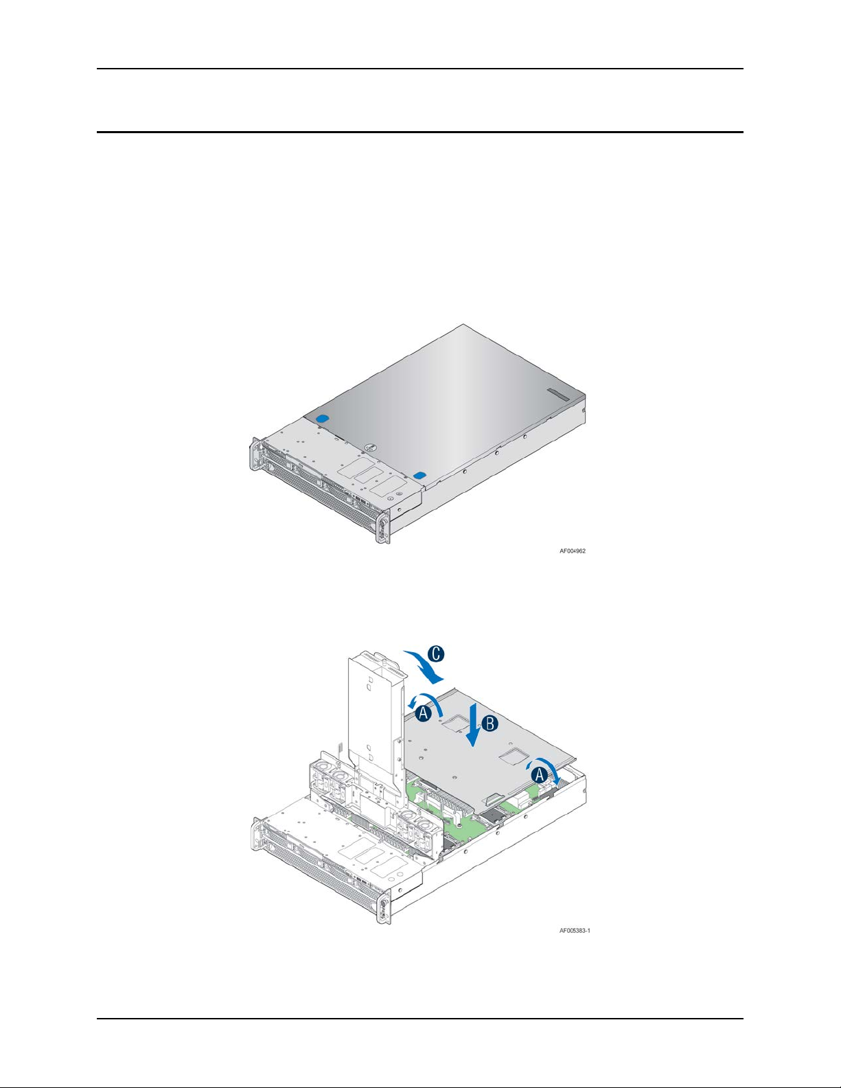
Figure 1. System Overview ......................................................................................................... 3
Figure 2. System Assembly......................................................................................................... 3
Figure 3. Chassis Dimensions ..................................................................................................... 6
Figure 4. System Components Overview .................................................................................... 9
Figure 5. 2.5" Hot Swap Hard Drive Bay - 8 Drive Configuration ................................................. 9
Figure 6. 3.5" Hotswap Hard Drive Bay - 4 Drive Configuration ................................................... 9
Figure 7. Back Panel Feature Identification ............................................................................... 10
Figure 8. Front Control Panel Options ....................................................................................... 10
Figure 9. Intel® Server Board S4600LH2/LT2 ............................................................................ 12
Figure 10. Optional Front Bezel (Intel Product Order Code – A2UBEZEL) ................................ 13
Figure 11. Installing the Front Bezel .......................................................................................... 13
Figure 12. Power Supply ........................................................................................................... 15
Figure 13. Power Supply Module Mechanical Drawing .............................................................. 16
Figure 14. Power Supply Module .............................................................................................. 16
Figure 15. AC and DC Power Supplies – Connector View ........................................................ 17
Figure 16. AC Power Cord ........................................................................................................ 20
Figure 17. DC Power Cord ........................................................................................................ 20
Figure 18. 75VDC Test ............................................................................................................. 27
Figure 19. 0VDC Test ............................................................................................................... 28
Figure 20. Fan Control Model .................................................................................................... 38
Figure 21. System Fan Identification ......................................................................................... 39
Figure 22. System Fan Assembly.............................................................................................. 40
Figure 23. Upper and Lower System Fan Connections ............................................................. 41
Figure 24. Lower Fan Board ...................................................................................................... 41
Figure 25. Lower Fan Board Dimensions .................................................................................. 42
Figure 26. Upper Fans Connectors on PDB .............................................................................. 42
Figure 27. 8 x 2.5" Hard Drive Configuration ............................................................................. 44
Figure 28. 2.5” Hard Disk Drive Assembly ................................................................................. 45
Figure 29. 2.5” Drive LEDs ........................................................................................................ 45
Figure 30. 2.5” Drive Hot-Swap Backplane Assembly ............................................................... 46
Figure 31. 2.5” Drive Hot-Swap Backplane – Front Side ........................................................... 46
Figure 32. 2.5” Drive Hot-Swap Backplane – Back Side ............................................................ 47
Figure 33. 4 x 3.5" Hard Drive Configuration ............................................................................. 48
Figure 34. 3.5” Hard Disk Drive Assembly ................................................................................. 48
Figure 35. 3.5” Drive LEDs ........................................................................................................ 49
Figure 36. 3.5” Drive Hot-Swap Backplane Assembly ............................................................... 50
Figure 37. 3.5” Drive Hot-Swap Backplane – Front Side ........................................................... 50
Figure 38. 3.5” Drive Hot-Swap Backplane – Back Side ............................................................ 51
Figure 39. Optical Drive Support ............................................................................................... 52
Revision 1.0
Page 8

List of Figures Intel® Server System R2000LH2/T2 Product Family TPS
viii
Figure 40. Optical Drive Assembly ............................................................................................ 52
Figure 41. 2.5" Solid State Drive (SSD) Mounting Option .......................................................... 53
Figure 42. Low Profile eUSB SSD Support ............................................................................... 54
Figure 43. InnoDisk* Low Profile SATA DOM ............................................................................ 55
Figure 44. Embedded SATA/SAS Controller Support ................................................................ 56
Figure 45. Front I/O Panel Features .......................................................................................... 60
Figure 46. Front Control Panel Features ................................................................................... 61
Figure 47. Intel® Local Control Panel Option ............................................................................. 65
Figure 48. LCP Background Color during Normal Operation ..................................................... 66
Figure 49. LCP Background Color during an Error .................................................................... 66
Figure 50. LCP Main Menu ....................................................................................................... 68
Figure 51. LCP Event Menu ...................................................................................................... 69
Figure 52. LCP View Menu ....................................................................................................... 70
Figure 53. System Firmware Versions Menu ............................................................................. 70
Figure 54. System Information Menu ........................................................................................ 70
Figure 55. LCP – BMC IP Configuration .................................................................................... 71
Figure 56. LCP – RMM4 IP Configuration ................................................................................. 71
Figure 57. LCP – Power Consumed by the System Currently ................................................... 72
Figure 58. LCP – Last BIOS Post Code .................................................................................... 72
Figure 59. LCP – Configure Menu Items ................................................................................... 73
Figure 60. LCP – IP Version Configuration Screen ................................................................... 73
Figure 61. LCP – BMC IP Configuration Menu .......................................................................... 73
Figure 62. LCP – BMC IP Source Configuration Menu .............................................................. 73
Figure 63. Screen shots for Configuring IP Address, Subnet Mask, and Gateway .................... 74
Figure 64. State Transition Diagram for Setting IP Address ...................................................... 75
Figure 65. Boot Options Configuration Menu ............................................................................ 75
Figure 66. Banner Configuration Menu ..................................................................................... 76
Figure 67. PCIe Risers and Add-in Cards ................................................................................. 78
Figure 68. GPGPU Cable .......................................................................................................... 79
Figure 69. IO Riser CPU Mapping ............................................................................................. 81
Figure 70. Right Riser Card Drawing ......................................................................................... 82
Figure 71. Left Riser Card Drawing ........................................................................................... 82
Figure 72. PDB ......................................................................................................................... 83
Figure 73. Upper Fans Connectors on PDB .............................................................................. 87
Figure 74. PDB Drawing ........................................................................................................... 88
Figure 75. SSI Common Front Panel Board .............................................................................. 89
Figure 76. Mezzanine Support .................................................................................................. 90
Figure 77. RMM4 Installation .................................................................................................... 91
Figure 78. PECI Proxy .............................................................................................................. 94
Figure 79. POST Diagnostic LED Location ............................................................................... 98
Revision 1.0
Page 9

Intel® Server System R2000LH2/T2 Product Family TPS List of Tables
ix
List of Tables
Table 1. Server System ............................................................................................................... 4
Table 2. System Feature Set ....................................................................................................... 4
Table 3. System Environmental Limits Summary ........................................................................ 7
Table 4 Front Control Panel Options ......................................................................................... 10
Table 5. Power Supply Module Output Power Connector Pin-out ............................................. 18
Table 6. 1600 Watt (AC) Power Supply Efficiency (Gold) .......................................................... 19
Table 7. AC Power Cord Specifications .................................................................................... 20
Table 8. Power Factor ............................................................................................................... 21
Table 9. AC Input Voltage Range .............................................................................................. 21
Table 10. AC Line Dropout/Holdup ............................................................................................ 22
Table 11. AC Line Sag Transient Performance ......................................................................... 22
Table 12. AC Line Surge Transient Performance ...................................................................... 23
Table 13. Performance Criteria ................................................................................................. 23
Table 14. Power Supply Over Current Protection ...................................................................... 24
Table 15. Over Voltage Protection (OVP) Limits ....................................................................... 25
Table 16. 1600 Watt (DC) Power Supply Efficiency (Platinum) ................................................. 26
Table 17. 1600 Watt (DC) Power Supply Efficiency (Platinum) ................................................. 26
Table 18. DC Holdup/Dropout Time .......................................................................................... 26
Table 19. Line Voltage Transient Limits .................................................................................... 28
Table 20. Over Current Protection............................................................................................. 29
Table 21. Over Voltage Protection Limits .................................................................................. 29
Table 22. Example Load Share Threshold for Activating Supplies ............................................ 30
Table 23. LED Indicators ........................................................................................................... 32
Table 24. Lower Fan Connector Pin-out .................................................................................... 41
Table 25. Upper Fan Connector Pin-out (Fans 8-11) ................................................................. 42
Table 26. 2.5” Drive Status LED States ..................................................................................... 45
Table 27. 2.5” Drive Activity LED States.................................................................................... 45
Table 28. 3.5” Drive Status LED States ..................................................................................... 49
Table 29. 3.5” Drive Activity LED States.................................................................................... 49
Table 30. Intel® RAID C600 Upgrade Key Options .................................................................... 57
Table 31. System Status LED State Definitions......................................................................... 62
Table 32. Power/Sleep LED Functional States .......................................................................... 64
Table 33. GPGPU Aux Connector Pin-out (J9 and J10) ............................................................ 79
Table 34. Wattage Limitation of PCIe Loading .......................................................................... 80
Table 35. Over Current Protection Circuits ................................................................................ 83
Table 36. Power Supply Card Edge Connector Pin-out P8 and P9 ........................................... 84
Table 37. Main Power (J8) Connector Pin-out ........................................................................... 85
Table 38. Main Power (J6) Connector Pin-out ........................................................................... 85
Table 39. Power Control Signals Pin-out (J5) ............................................................................ 86
Revision 1.0
Page 10

List of Tables Intel® Server System R2000LH2/T2 Product Family TPS
x
Table 40. GPGPU Aux Connector Pin-out (J9 and J10) ............................................................ 86
Table 41. Upper Fan Connector Pin-out (Fans 8-11) ................................................................ 87
Table 42. SSI Front Panel Connector Pin-out (Baseboard) ....................................................... 89
Table 43. Intel® I/O Modules ..................................................................................................... 90
Table 44. POST Progress Code LED Example ......................................................................... 99
Table 45. POST Progress Codes .............................................................................................. 99
Table 46. MRC Progress Codes ............................................................................................. 102
Table 47. MRC Fatal Error Codes ........................................................................................... 103
Table 48. POST Error Messages and Handling ....................................................................... 105
Table 49. POST Error Beep Codes ......................................................................................... 110
Table 50. Integrated BMC Beep Codes ................................................................................... 110
Revision 1.0
Page 11

Intel® Server System R2000LH2/T2 Product Family TPS List of Tables
xi
< This page intentionally left blank. >
Revision 1.0
Page 12

Page 13

Intel® Server System R2000LH2/T2 Product Family TPS Introduction
1
1.1 Chapter Outline
1. Introduction
This Technical Product Specification (TPS) provides system level information for the Intel®
Server System R2000LH2 and Intel
level features of both these product families are common, however the server board integrated
into them is different. The Intel
®
Intel
Server Board S4600LH2 and the Intel® Server System R2000LTH2 product family is
integrated with the Intel
®
Server Board S4600LT2.
®
Server System R2000LT2 product families. The system
®
Server System R2000LH2 product family is integrated with an
This document describes the functions and features of the integrated server system which
includes the chassis layout, system boards, power subsystem, cooling subsystem, storage
subsystem options, and available installable options. Server board specific details can be
obtained by referencing the Intel
®
Server Boards S4600LH2/T2 Product Specification.
In addition, design-level information related to specific server board components or subsystems
can be obtained by ordering External Product Specifications (EPS) or External Design
Specifications (EDS) related to this server generation. EPS and EDS documents are made
available under NDA with Intel and must be ordered through your local Intel representative. See
the Reference Documents
section for a complete list of available documents.
This document is divided into the following chapters:
Chapter 1 – Introduction
Chapter 2 – Product Family Overview
Chapter 3 – Power Subsystem
Chapter 4 – Thermal Management
Chapter 5 – System Storage and Peripherals Drive Bay Overview
Chapter 6 – Storage Controller Options Overview
Chapter 7 – Front Control Panel and I/O Panel Overview
Chapter 8 – Intel
Chapter 9 – PCI Riser Card Support
Chapter 10 – Additional System Boards
Chapter 11 – Front P anel
Chapter 12 – IO Module Support
Chapter 13 –Intel
Appendix A – Integration and Usage Tips
Appendix B – POST Code Diagnostic LED Decoder
Appendix C – Post Code Errors
Glossary
Reference Documents
®
Local Control Panel
®
Intelligent Power Node Manager (NM)
Revision 1.0
Page 14

Introduction Intel® Server System R2000LH2/T2 Product Family TPS
2
1.2 Server Board Use Disclaimer
Intel Corporation server boards support add-in peripherals and contain a number of high-density
Very Large Scale Integration (VLSI) and power delivery components that need adequate airflow
to cool. Intel ensures through its own chassis development and testing that when Intel
building blocks are used together, the fully integrated system will meet the intended thermal
requirements of these components. It is the responsibility of the system integrator who chooses
not to use Intel developed server building blocks to consult vendor datasheets and operating
parameters to determine the amount of airflow required for their specific application and
environmental conditions. Intel Corporation cannot be held responsible if components fail or the
server board does not operate correctly when used outside any of their published operating or
non-operating limits.
®
server
Revision 1.0
Page 15
Intel® Server System R2000LH2/T2 Product Family TPS Product Family Overview
3
Figure 1. System Overview
Figure 2. System Assembly
2. Product Family Overview
This generation of Intel 2U server platforms offers a variety of system options to meet the varied
configuration r equirements of high-density high-performance computing environments. The
®
Intel
Server System R2000LH2 and Intel® Server System R2000LT2 servers are comprised of
several available 2U rack mount server systems that are integrated with either an Intel
Board S4600LH2 or Intel
®
Server Board S4600LT2.
This chapter provides a high-level overview of the system features and available options as
supported in different platform SKUs within this server family. Greater detail for each major
system component or feature is provided in the following chapters.
®
Server
Revision 1.0
Page 16
Product Family Overview Intel® Server System R2000LH2/T2 Product Family TPS
4
Table 1. Server System
Server System
Integrated Server Board
Intel® Server System R2000LH2
Intel® Server Board S4600LH2
Intel® Server System R2000LT2
Intel® Server Board S4600LT2
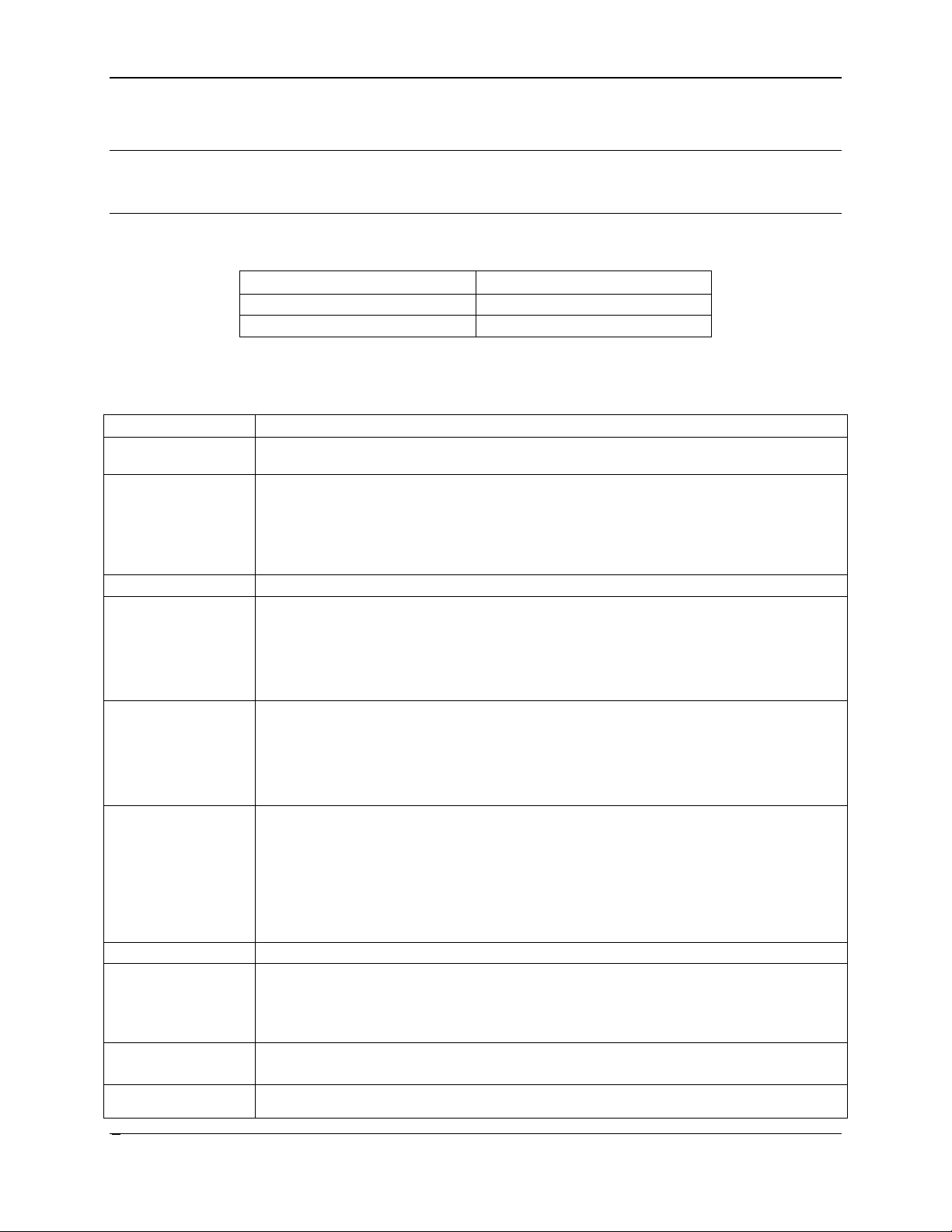
Table 2. System Feature Set
Feature
Description
Processor support
Support for up to four Intel® Xeon® processors E5-4600 product family with a Thermal
Memory
48 DIMM slots – 3 DIMMs / Channel – 4 memory channels per processor
Chipset
Intel® C600-A chipset with support for optional Storage Option Select keys
External I/O
DB-15 Video connector (Rear)
Internal I/O
One 2x5 pin connector providing front panel support for two USB ports
Optional I/O Module
The following I/O modules utilize a single proprietary on-board connector. An installed I/O
System Fans
11 managed system fan headers
Riser Cards
Two riser card slots:
Video Integrated 2D Video Controller
On-board storage
controllers and
One eUSB 2x5 pin connector to support 2mm low-profile eUSB solid state devices
Note: Table 2
lists features common to both server product families. Features that are unique to
one product family are identified by either denoting the server system name or the integrated
server board name.
Design Power (TDP) of up to 130 W
Unbuffered DDR3 (UDIMM), registered DDR3 (RDIMM), Load Reduced DDR3
(LRDIMM)
Memory DDR3 data transfer r ates of 800, 1066, 1333, and 1600 MT/s
DDR3 standard I/O voltage of 1.5V and DDR3 Low Voltage of 1.35V
connections
RJ-45 Serial Port A connector
S4600LH2 Dual-port Network Interface supporting 10/100/1000Mbps
S4600LT2 Dual-port Network Interface supporting 100/1000/10000Mbps
6 USB 2.0 connectors (4 rear + 2 front)
connectors / headers
support
One Type-A USB 2.0 connector
One 2x15 pin SSI-EEB compliant front panel header
One 2x7pin Front Panel Video connector
One DH-10 Serial Port B connector
module can be supported in addition to standard on-board features and any add-in
expansion cards.
Quad port 1 GbE based on Intel® Ethernet Controller I350 – RMS25CB0080
Dual port 10GBase-T Ethernet module based on Intel® Ethernet Controller I350
Dual SFP+ port 10GbE module based on Intel® 82500 10 GbE controller
Single Port FDR speed Infiniband* module with QSFP connector
Each riser card slot has a total of 48 PCIe lanes routed to them.
Each riser card slot supports various Full Height Full Length (FHFL) and Full Height
Half Length (FHHL) cards.
16 MB DDR3 Memory
Revision 1.0
Page 17

Intel® Server System R2000LH2/T2 Product Family TPS Product Family Overview
5
Feature
Description
options
Two 7-pin single port AHCI SATA connectors capable of supporting up to 6 GB/sec
Security
TPM Module AXXTPME5 (Accessory Option)
Server Management
Integrated Baseboard Management Controller, IPMI 2.0 compliant
Power Supply
The server system can have up to two power supply modules installed, providing
Storage Bay Options
8x – 2.5” SATA/SAS Hot Swap Hard Drive Bays
Available Rack
Tool-less rack mount premium rail kit – Intel Product Code – AXXPRAIL
Two SCU 4-port mini-SAS connectors capable of supporting up to 3 GB/sec
SAS/SATA
®
Intel
Support for Intel® Server Management Software
Intel® Remote Management Module 4 Lite – Accessory Option
Intel® Remote Management Module 4 Management NIC – Accessory Option
RAID C600 Upgrade Key support providing optional expanded SATA/SAS RAID
capabilities
Options
Mount Kit Options
support for the following power configurations: 1+0, 1+1 Redundant Power, and 2+0
Combined Power
Two power supply options:
AC 1600W
DC 1600W
4x – 3.5” SATA/SAS Hot Swap Hard Drive Bays
4x – 3.5” SATA/SAS Fixed Hard Drive Bays
Value rack mount rail kit – Intel Product Code – AXXVRAIL
Cable Management Arm – Intel Product Code – AXX1U2UCMA (*supported with
AXXPRAIL only)
2-post fixed mount bracket kit – Intel Product Code – AXX2POSTBRCKT
Revision 1.0
Page 18
Product Family Overview Intel® Server System R2000LH2/T2 Product Family TPS
6
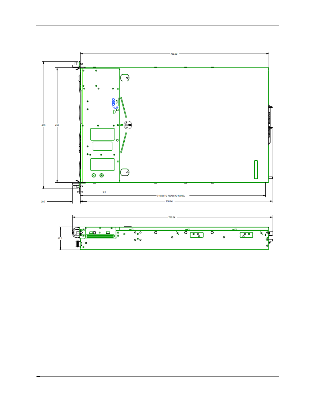
2.1 Chassis Dimensions
Figure 3. Chassis Dimensions
Revision 1.0
Page 19
Intel® Server System R2000LH2/T2 Product Family TPS Product Family Overview
7
2.2 System Level Environmental Limits
Table 3. System Environmental Limits Summary
Parameter
Limits
Temperature
Operating
ASHRAE Class A2 – Continuous Operation. 10ºC to 35ºC 1 (50ºF to 95ºF)
ASHRAE Class A3 – Includes operation up to 40ºC for up to 900 hrs. per
ASHRAE Class A4 – Includes operation up to 45ºC for up to 90 hrs. per
Shipping
-40ºC to 70ºC (-40ºF to 158ºF)
Altitude
Operating
Support operation up to 3050m with ASHRAE class deratings
Humidity
Shipping
50% to 90%, non-condensing with a maximum wet bulb of 28°C (at
Shock
Operating
Half sine, 2g, 11 mSec
Unpackaged
Trapezoidal, 25 g, velocity change is based on packaged weight
Packaged
Product Weight: ≥ 40 to < 80
Vibration
Unpackaged
5 Hz to 500 Hz 2.20 g RMS random
Packaged
5 Hz to 500 Hz 1.09 g RMS random
AC-DC
Voltage
90 Hz to 132 V and 180 V to 264 V
Frequency
47 Hz to 63 Hz
Source Interrupt
No loss of data for power line drop-out of 12 mSec
Surge Non-
Unidirectional
Line to earth
AC Leads 2.0 kV
ESD
Air Discharged
12.0 kV
Contact
8.0 kV
Acoustics
Power in Watts
<300 W ≥300 W ≥600 W ≥1000 W
Servers/Rack
7.0 7.0 7.0 7.0
The following table defines the system level operating and non-operating environmental limits.
with the maximum rate of change not to exceed 10°C per hour
year
year
temperatures from 25°C to 35°C)
Sound Power
Measured
operating and
operating
Only
Discharge
Non-palletized Free Fall Height = 18 inches
Palletized (single product) Free Fall Height = NA
I/O Leads 1.0 kV
DC Leads 0.5 kV
Mount BA
Revision 1.0
Page 20

Product Family Overview Intel® Server System R2000LH2/T2 Product Family TPS
8
Note:
1. Intel Corporation server boards contain a number of high-density VLSI and power delivery components that
need adequate airflow to cool. Intel ensures through its own chassis development and testing that when
®
server building blocks are used together, the fully integrated system will meet the intended thermal
Intel
requirements of these components. It is the responsibility of the system integrator who chooses not to use
Intel developed server building blocks to consult vendor datasheets and operating parameters to determine
the amount of airflow required for their specific application and environmental conditions. Intel Corporation
cannot be held responsible if components fail or the server board does not operate correctly when used
outside any of its published operating or non-operati ng limits.
Disclaimer Note: Intel ensures the unpackaged server board and system meet the shock
requirement mentioned above through its own chassis development and system configuration. It
is the responsibility of the system integrator to determine the proper shock level of the board
and system if the system integrator chooses different system configuration or different chassis.
Intel Corporation cannot be held responsible, if components fail or the server board does not
operate correctly when used outside any of its published operating or non-operating limits.
See the Intel® Server Board S4600LH2/T2 Power Budget and Thermal Configuration Guidelines
Tool for system configuration requirements and limitations.
Revision 1.0
Page 21
Intel® Server System R2000LH2/T2 Product Family TPS Product Family Overview
9
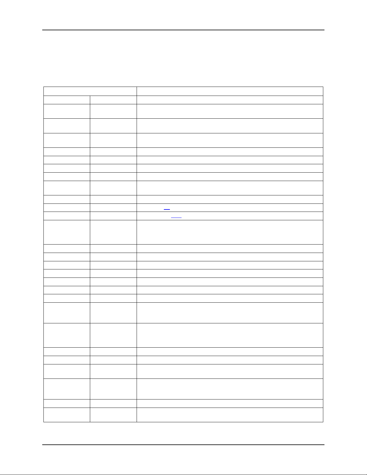
2.3 System Features and Options Overview
Figure 4. System Components Overview
2.3.1
Hot Swap Hard Drive Bay and Front Panel Options
Figure 5. 2.5" Hot Swap Hard Drive Bay - 8 Drive Configuration
Figure 6. 3.5" Hotswap Hard Drive Bay - 4 Drive Configuration
Revision 1.0
Page 22
Product Family Overview Intel® Server System R2000LH2/T2 Product Family TPS
10
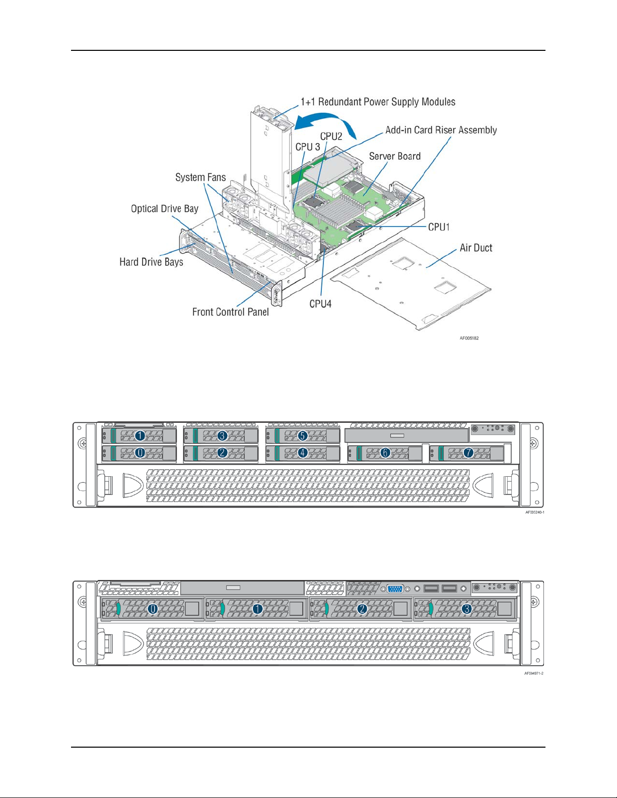
2.3.2
Back Panel Features
Figure 7. Back Panel Feature Identification
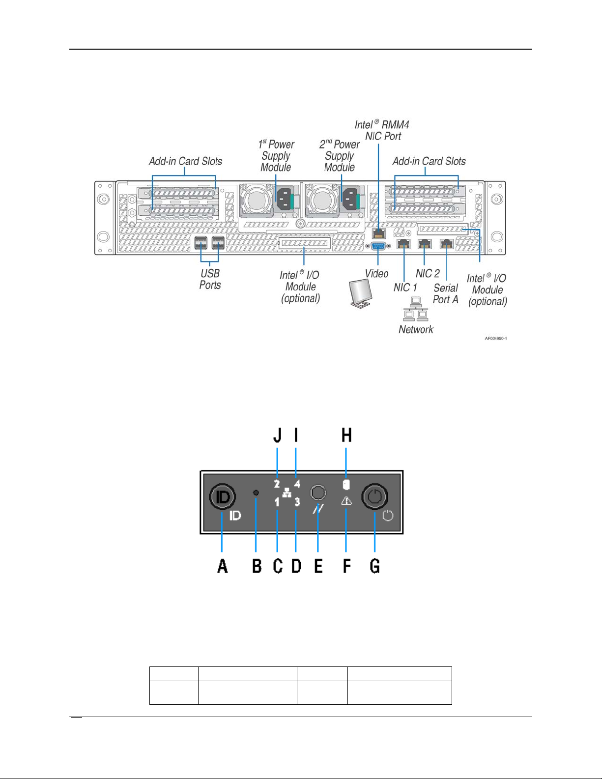
2.3.3
Front Control Panel Options
Figure 8. Front Control Panel Options
Table 4 Front Control Panel Options
Label
Description
Label
Description
A
System ID Button
F
System Status LED
w/Integrated LED
Revision 1.0
Page 23

Intel® Server System R2000LH2/T2 Product Family TPS Product Family Overview
11
Label
Description
Label
Description
B
NMI Button (recessed,
G
Power Button
C
NIC-1 Activity LED
H
Hard Drive Activity LED
D
Not used
I
Not used
E
System Cold Reset
J
NIC-2 Activity LED
tool required for use)
Button
w/Integrated LED
Revision 1.0
Page 24
Product Family Overview Intel® Server System R2000LH2/T2 Product Family TPS
12
2.4 Server Board Features Overview
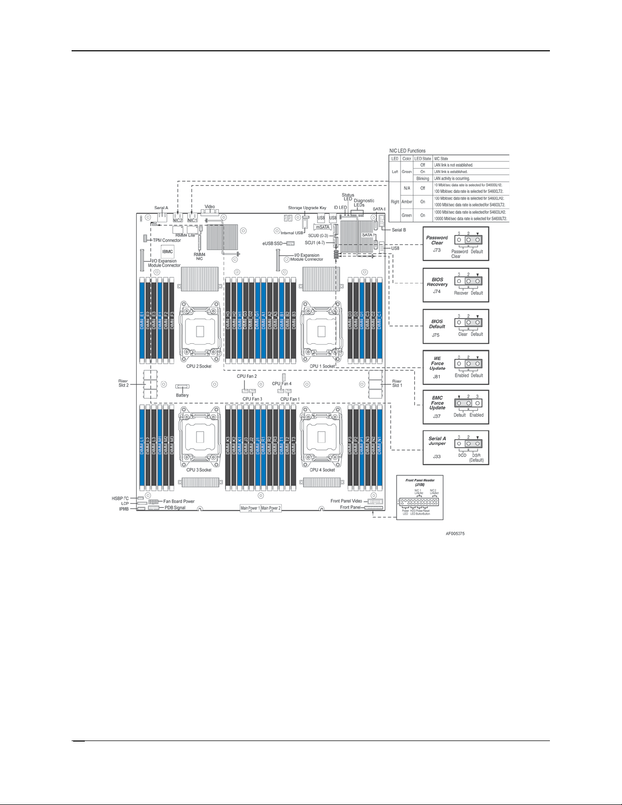
Figure 9. Intel® Server Board S4600LH2/LT2
The following illustration provides a general overview of the server board, identifying key feature
and component locations. The majority of the items identified are common for the Intel
®
Server
Board S4600LH2 and S4600LH2. The accompanying table identifies variations when present.
Revision 1.0
Page 25
Intel® Server System R2000LH2/T2 Product Family TPS Product Family Overview
13
2.5 Available Front Bezel Support
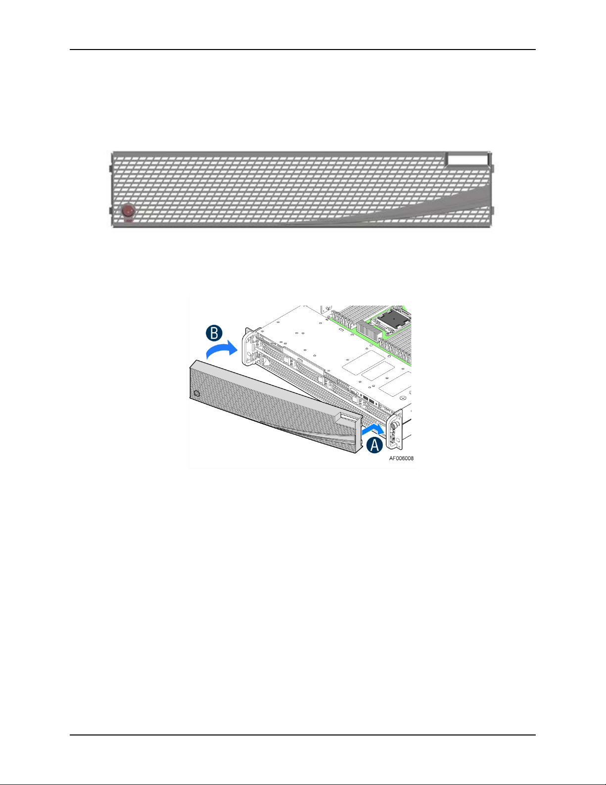
Figure 10. Optional Front Bezel (Intel Product Order Code – A2UBEZEL)
Figure 11. Installing the Front Bezel
The optional front bezel is made of molded plastic and uses a snap-on design. When installed,
its design allows for maximum airflow to maintain system cooling requirements. The bezel
assembly includes snap-in options that can be used for customization.
Revision 1.0
Page 26

Product Family Overview Intel® Server System R2000LH2/T2 Product Family TPS
14
2.6 Available Rack and Cabinet Mounting Kit Options
Tool-less rack mount rail kit – Intel Product Code – AXXPRAIL
- 2U compatible
- 65 lbs. max support weight
- Tool-less installation
- Full extension from rack
- Drop in system install
- Optional cable management arm support
Cable Management Arm – Intel Product Code – AXX1U2UCMA (*supported with
AXXPRAIL only)
2-Post Fixed mount bracket kit – Intel Product Code – AXX2POSTBRCKT
Revision 1.0
Page 27
Intel® Server System R2000LH2/T2 Product Family TPS Power Subsystem
15
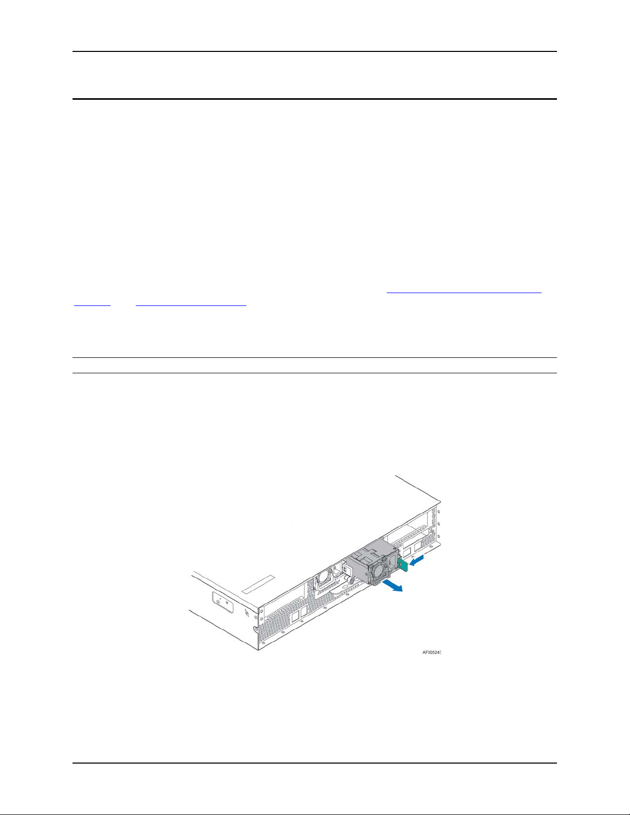
Figure 12. Power Supply
3. Power Subsystem
This chapter provides a high level overview of the power management features and
specification data for the power supply options available for this server product. Specification
variations are identified for each supported power supply.
The server system can have up to two power supply modules installed, supporting the following
power supply configurations: 1+0 (single power supply), 1+1 redundant power, and 2+0
combined power (non-redundant).The 1+1 redundant power and 2+0 combined power
configurations are automatically configured depending on the total power draw of the system. If
the total system power draw exceeds the power capacity of a single power supply module, the
power from the second power supply module will be utilized. If this occurs, power redundancy
will be lost. In a 2+0 power configuration, the total power available may be less than twice the
rated power of the installed power supply modules due to the amount of heat produced with
both supplies providing peak power. If system thermals exceed programmed limits, platform
management will attempt to keep the system operational. See
(CLST) and Thermal Management for det ails.
There are two power supply options available for this server product: 1600W AC and 1600W
DC.
Closed Loop System Throttling
Note: Mixing of AC and DC power supplies in the same system is unsupported.
The power supplies are modular, allowing for tool-less insertion and extraction from a bay in the
back of the chassis. When inserted, the card edge connector of the power supply mates blindly
to a matching slot connector on the server board.
In the event of a power supply failure, redundant 1+1 power supply configurations support hotswap extraction and insertion.
The AC input is auto-ranging and power factor corrected.
Revision 1.0
Page 28
Power Subsystem Intel® Server System R2000LH2/T2 Product Family TPS
16
3.1 Mechanical Overview
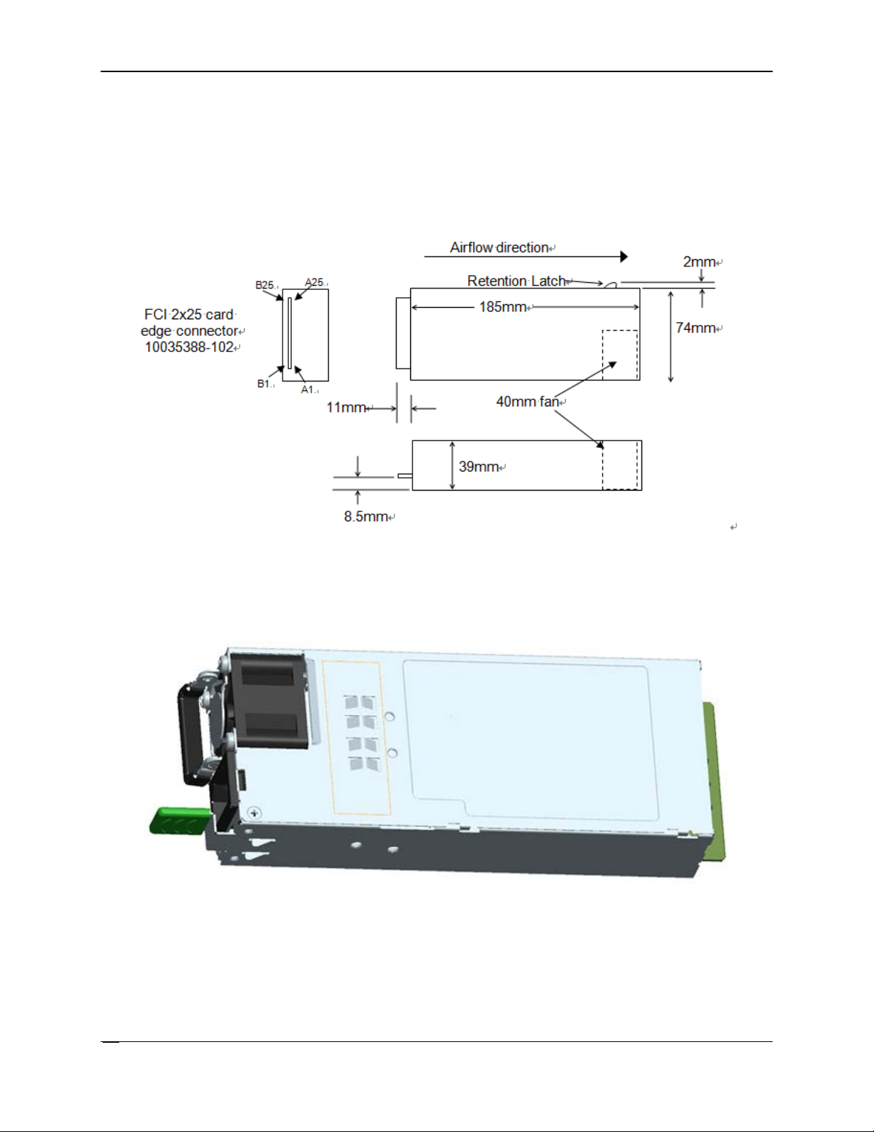
Figure 13. Power Supply Module Mechanical Drawing
Figure 14. Power Supply Module
The physical size of the power supply enclosure is 39/40mm x 74mm x 185mm. The power
supply contains a single 40mm fan. The power supply has a card edge output that interfaces
with a 2x25 card edge connector in the system. The AC plugs directly into the external face of
the power supply.
Revision 1.0
Page 29
Intel® Server System R2000LH2/T2 Product Family TPS Power Subsystem
17
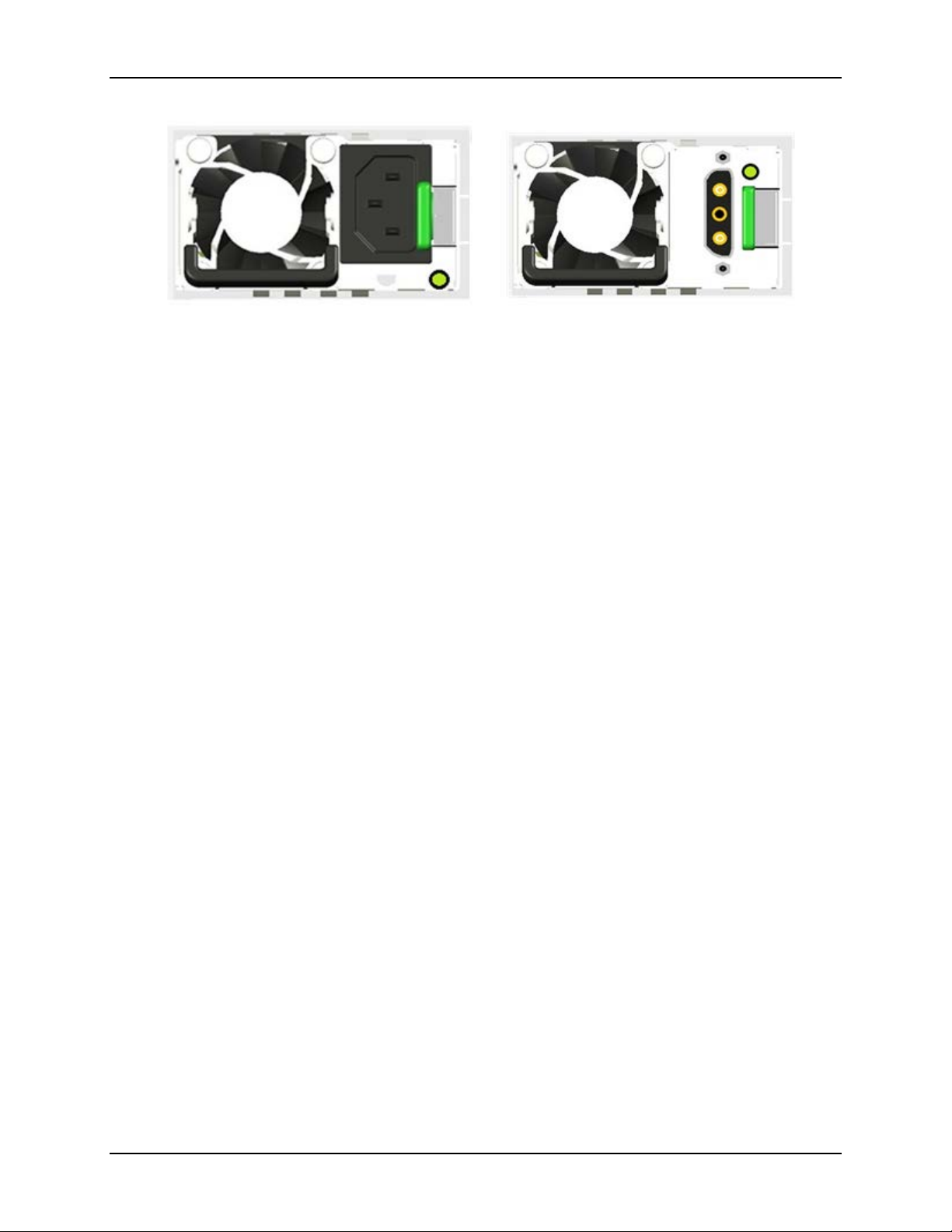
Figure 15. AC and DC Power Supplies – Connector View
Revision 1.0
Page 30

Power Subsystem Intel® Server System R2000LH2/T2 Product Family TPS
18
3.2 Power Connectors
3.2.1
Power Supply Module Card Edge Connector
Table 5. Power Supply Module Output Power Connector Pin-out
Pin
Name
Pin
Name
A1
GND
B1
GND
A2
GND
B2
GND
A3
GND
B3
GND
A4
GND
B4
GND
A5
GND
B5
GND
A6
GND
B6
GND
A7
GND
B7
GND
A8
GND
B8
GND
A9
GND
B9
GND
A10
+12V
B10
+12V
A11
+12V
B11
+12V
A12
+12V
B12
+12V
A13
+12V
B13
+12V
A14
+12V
B14
+12V
A15
+12V
B15
+12V
A16
+12V
B16
+12V
A17
+12V
B17
+12V
A18
+12V
B18
+12V
A19
PMBus SDA
B19
A0 (SMBus address)
A20
PMBus SCL
B20
A1 (SMBus address)
A21
PSON
B21
12V stby
A22
SMBAlert#
B22
Cold Redundancy Bus
A23
Return Sense
B23
12V load share bus
A24
+12V remote Sense
B24
No Connect
A25
PWOK
B25
Compatibility Check
Each power supply module has a single 2x25 card edge output connection that plugs directly
into a matching slot connector on the server board. The connector provides both power and
communication signals to the server board. The following table defines the connector pin-out.
The connector pin out in table applies to the 1600W (AC) and 1600W (DC) power supplies.
Note: Mixing of AC and DC power supplies in the same system is unsupported.
pin*
Revision 1.0
Page 31

Intel® Server System R2000LH2/T2 Product Family TPS Power Subsystem
19
3.3 Power Supply Module Efficiency
Table 6. 1600 Watt (AC) Power Supply Efficiency (Gold)
Loading
100% of
maximum
50% of
maximum
20% of
maximum
10% of
maximum
Minimum
91%
94%
90%
82%
The following table provides the required minimum efficiency level at various loading conditions.
These are provided at three different load levels: 100%, 50%, and 20%. Efficiency is tested over
an AC input voltage range of 115 VAC to 220 VAC.
Efficiency
Revision 1.0
Page 32

Power Subsystem Intel® Server System R2000LH2/T2 Product Family TPS
20
3.4 AC and DC Power Cord Specification Requirements
Table 7. AC Power Cord Specifications
Cable Type
SJT
Wire S ize
16 AWG
Temperature Rating
105ºC
Amperage Rating
13 A
Voltage Rating
125 V
Figure 16. AC Power Cord
Figure 17. DC Power Cord
The AC and DC power cords used meet the specification requirements listed in the following
tables and figures.
Revision 1.0
Page 33

Intel® Server System R2000LH2/T2 Product Family TPS Power Subsystem
21
3.5 AC Input Specifications
3.5.1
Power Factor
Table 8. Power Factor
Output power
10% load
20% load
50% load
100% load
Power factor 1600w
> 0.80
> 0.90
> 0.90
> 0.95
3.5.2
AC Input Voltage Specification
Table 9. AC Input Voltage Range
Parameter
Min
Rated
Max
Start Up VAC
Power Off VAC
Voltage (110)
90 Vrms
100-127 Vrms
140 Vrms
85VAC +/-
70VAC +/Voltage (220)
180 Vrms
200-240 Vrms
264 Vrms
Frequency
47 Hz
50/60
63 Hz
3.5.3
AC Line Isolation Requirements
3.5.4
AC Line Dropout/Holdup
The power supply meets the power factor requirements stated in the Energy Star Program
Requirements for Computer Servers. These requirements are stated below.
AC
Note: Tested at 230VAC, 50Hz and 60Hz and 115VAC, 60Hz
The power supply operates within all specified limits over the following input voltage range.
Harmonic distortion of up to 10% of the rated line voltage does not cause the power supply to
go out of specified limits. Application of an input voltage below 85VAC does not cause damage
to the power supply, including a blown fuse.
4VAC
Note:
1. Maximum input current at low input voltage range is measured at 90VAC, at max load.
2. Maximum input current at high input voltage range is measured at 180VAC, at max load.
3. This requirement is not to be used for determining agency input current markings.
5VAC
The power supply meets all safety agency requirements for dielectric strength. Transformers’
isolation between primary and secondary windings complies with the 3000VAC (4242VDC)
dielectric strength criteria. If the working voltage between primary and secondary dictates a
higher dielectric strength test voltage, the highest test voltage will be used. In addition the
insulation system complies with reinforced insulation per safety standard IEC 950. Separation
between the primary and secondary circuits, and primary to ground circuits, complies with the
IEC 950 spacing requirements.
An AC line dropout is defined to be when the AC input drops to 0VAC at any phase of the AC
line for any length of time. During an AC dropout the power supply meets dynamic voltage
regulation requirements. An AC line dropout of any duration does not cause tripping of control
signals or protection circuits. If the AC dropout lasts longer than the holdup time, the power
supply will recover and meet all turn on requirements. The power supply meets the AC dropout
Revision 1.0
Page 34

Power Subsystem Intel® Server System R2000LH2/T2 Product Family TPS
22
Table 10. AC Line Dropout/Holdup
Power Supply
Loading
Holdup Time
1600W AC
70%
10.0 msec
3.5.4.1
AC Line 12VSB Holdup
3.5.5
AC Line Fuse
3.5.6
AC Inrush
3.5.7
AC Line Transient Specification
Table 11. AC Line Sag Transient Performance
AC Line Sag (10sec interval between each sagging)
Duration
Sag
Operating AC Voltage
Line Frequency
Performance Criteria
0 to 1/2 AC
95%
Nominal AC Voltage
50/60 Hz
No loss of function or
> 1 AC cycle
> 30%
Nominal AC Voltage
50/60 Hz
Loss of function acceptable,
requirement over rated AC voltages and frequencies. A dropout of the AC line for any duration
does not cause damage to the power supply.
The 12VSB output voltage stays in regulation under its full load (static or dynamic) during an AC
dropout of 70ms min (=12VSB holdup time) whether the power supply is in ON or OFF state
(PSON asserted or de-asserted).
The power supply has one line fused in the single line fuse on the line (Hot) wire of the AC
input. The line fusing is acceptable for all safety agency requirements. The input fuse is a slow
blow type. The AC inrush current does not cause the AC line fuse to blow under any conditions.
All protection circuits in the power supply will not cause the AC fuse to blow unless a component
in the power supply has failed. This includes DC output load short conditions.
The AC line inrush current does not exceed 65A peak, for up to one-quarter of the AC cycle,
after which, the input current is no more than the specified maximum input current. The peak
inrush current is less than the ratings of its critical components (including input fuse, bulk
rectifiers, and surge limiting device).
The power supply meets the inrush requirements for any rated AC voltage, during turn on at any
phase of AC voltage, during a single cycle AC dropout condition as well as upon recovery after
AC dropout of any duration, and over the specified temperature range (T
).
op
The AC line transient conditions are defined as sag and surge conditions. Sag conditions are
also commonly referred to as brownout; these conditions are defined as the conditions when the
AC line voltage drops below nominal voltage. Surge conditions are defined as the conditions
when the AC line voltage rises above nominal voltage.
The power supply meets the requirements under the following AC line sag and surge conditions.
cycle
ranges
ranges
performance
self-recoverable
Revision 1.0
Page 35

Intel® Server System R2000LH2/T2 Product Family TPS Power Subsystem
23
Table 12. AC Line Surge Transient Performance
AC Line Surge
Duration
Surge
Operating AC Voltage
Line Frequency
Performance Criteria
Continuous
10%
Nominal AC Voltages
50/60 Hz
No loss of function or
0 to 1/2 AC
30%
Mid-point of nominal AC
50/60 Hz
No loss of function or
3.5.8
Susceptibility Requirements
Table 13. Performance Criteria
Level
Description
A
The apparatus shall continue to operate as intended. No
B
The apparatus shall continue to operate as intended. No
C
Temporary loss of function is allowed provided the
3.5.9
Electrostatic Discharge Susceptibility
3.5.10
Fast Transient/Burst
3.5.11
Radiated Immunity
3.5.12
Surge Immunity
performance
cycle
Voltages
performance
The power supply meets the following electrical immunity requirements when connected to a
cage with an external EMI filter that meets the criteria defined in the SSI document EPS Power
Supply Specification. For further information on Intel standards, request a copy of the Intel
Environmental Standards Handbook.
degradation of performance.
degradation of performance beyond spec limits.
function is self-recoverable or can be restored by the
operation of the controls.
The power supply complies with the limits defined in EN 55024: 1998/A1: 2001/A2: 2003 using
the IEC 61000-4-2: Edition 1.2: 2001-04 test standard and performance criteria B defined in
Annex B of CISPR 24.
The power supply complies with the limits defined in EN55024: 1998/A1: 2001/A2: 2003 using
the IEC 61000-4-4: Second edition: 2004-07 test standard and performance criteria B defined in
Annex B of CISPR 24.
The power supply complies with the limits defined in EN55024: 1998/A1: 2001/A2: 2003 using
the IEC 61000-4-3: Edition 2.1: 2002-09 test standard and performance criteria A defined in
Annex B of CISPR 24.
The power supply is tested with the system for immunity to AC Unidirectional wave; 2kV line to
ground and 1kV line to line, per EN 55024: 1998/A1: 2001/A2: 2003, EN 61000-4-5: Edition
1.1:2001-04.
The pass criteria include:
Revision 1.0
Page 36

Power Subsystem Intel® Server System R2000LH2/T2 Product Family TPS
24
3.5.13
Power Recovery
3.5.14
Voltage Interruptions
3.5.15
Protection Circuits
3.5.16
Over-current Protection (OCP)
Table 14. Power Supply Over Current Protection
Power Supply
Output Voltage
Input voltage range
Over Current Limits
1600W AC
+12V
90 – 264VAC
180A min; 200A max
12VSB
90 – 264VAC
4A min; 5A max
3.5.17
Over-voltage Protection (OVP)
No unsafe operation is allowed under any condition.
All power supply output voltage levels to stay within proper spec levels.
No change in operating state or loss of data during and after the test profile.
No component damage under any condition.
The power supply complies with the limits defined in EN55024: 1998/A1: 2001/A2: 2003 using
the IEC 61000-4-5: Edition 1.1:2001-04 test standard and performance criteria B defined in
Annex B of CISPR 24.
The power supply recovers automatically after an AC power failure. AC power failure is defined
to be any loss of AC power that exceeds the dropout criteria.
The power supply complies with the limits defined in EN55024: 1998/A1: 2001/A2: 2003 using
the IEC 61000-4-11: Second Edition: 2004-03 test standard and performance criteria C defined
in Annex B of CISPR 24.
The protection circuits inside the power supply cause only the power supply’s main outputs to
shut down. If the power supply latches off due to a protection circuit tripping, an AC cycle OFF
for 15 seconds and a PSON# cycle HIGH for one second reset the power supply.
The power supply has current limit to prevent the outputs from exceeding the values shown in
table below. If the current limits are exceeded, the power supply will shut down and latch off.
The latch will be cleared by toggling the PSON# signal or by an AC power interr uption. The
power supply will not be damaged from repeated power cycling in this condition. 12VSB will be
auto-recovered after removing OCP limit.
The power supply over voltage protection is locally sensed. The power supply will shut down
and latch off after an over voltage condition occurs. This latch will be cleared by toggling the
PSON# signal or by an AC power interruption. The values are measured at the output of the
power supply’s connectors. The voltage will never exceed the maximum levels when measured
at the power connectors of the power supply connector during any single point of fail. The
voltage will never trip any lower than the minimum levels when measured at the power
connector. 12VSB will be auto-recovered after removing OVP limit.
Revision 1.0
Page 37

Intel® Server System R2000LH2/T2 Product Family TPS Power Subsystem
25
Table 15. Over Voltage Protection (OVP) Limits
Output Voltage
Min (V)
Max (V)
+12V
13.3
14.5
12VSB
13.3
14.5
3.5.18
Over-temperature Protection (OTP)
The power supply is protected against over temperature conditions caused by loss of fan
cooling or excessive ambient temperature. In an OTP condition the PSU will shut down. When
the power supply temperature drops to within specified limits, the power supply will restore
power automatically, while the 12VSB remains always on. The OTP circuit has built-in margin
so that the power supply will not oscillate on and off due to temperature recovering condition.
The OTP trip level has a minimum of 4°C of ambient temperature margin.
Revision 1.0
Page 38

Power Subsystem Intel® Server System R2000LH2/T2 Product Family TPS
26
3.6 1600W DC Power Supply Support
3.6.1
Power Supply Module Efficiency
Table 16. 1600 Watt (DC) Power Supply Efficiency (Platinum)
Loading
100% of
maximum
50% of
maximum
20% of
maximum
10% of
maximum
Minimum
88%
92%
88%
80%
3.6.2
DC Inlet Connector
3.6.3
DC Input Voltage Specification
Table 17. 1600 Watt (DC) Power Supply Efficiency (Platinum)
Parameter
Minimum
Rated
Maximum
Maximum Input
Current
DC Voltage
-38VDC
-48VDC/-60VDC
-75VDC
TBD
3.6.4
DC Holdup/Dropout Time
Table 18. DC Holdup/Dropout Time
Power Supply
Wattage
Loading
Holdup Time
1600W
1200W (75%)
0.2 msec
The following table provides the required minimum efficiency level at various loading conditions.
These are provided at three different load levels: 100%, 50%, and 20%. The input voltage is set
to -53VDC during the test.
Efficiency
The power supply has the -48VDC input fused. The fusing is acceptable for all safety agency
requirements. The DC inrush current does not caus e the fuse to blow under any conditions. No
protection circuits in the power supply will cause the DC fuse to blow unless a component in the
power supply has failed. This includes DC output load short conditions.
The power supply operates within all specified limits over the following input voltage range.
During a DC dropout of 0.2m s or less the power supply meets dynamic voltage regulation
requirements for every rated load condition. A DC line dropout of 0.2ms or less does not cause
tripping of control signals or protection circuits. Repeated every 10 seconds starting at the min
input voltage DC line dropout does not damage the power supply under any specified load
conditions. The PWOK signal does not go to a low state under these conditions. DC dropout
transients in excess of 0.2 milliseconds may cause shutdown of the PS or out of regulation
conditions, but do not damage the power supply. The power supply recovers and meets all turn
on requirements for DC dropouts that last longer than 0.2ms. The power supply meets the DC
dropout requirement over rated DC voltages and output loading conditions.
Revision 1.0
Page 39

Intel® Server System R2000LH2/T2 Product Family TPS Power Subsystem
27
3.6.5
DC Line Fuse
3.6.6
DC Inrush
3.6.7
DC Line Surge Voltages (Line Transients)
- 48VDC
<= 3.0ms
10.0ms
Rise TimeFall Time
<= 3.0ms
- 75VDC
Figure 18. 75VDC Test
The power supply has the -48VDC input fused. The fusing is acceptable for all safety agency
requirements. The DC inrush current does not cause the fuse to blow under any conditions. No
protection circuits in the power supply will cause the DC fuse to blow unless a component in the
power supply has failed. This includes DC output load short conditions.
The maximum inrush current from power-on is limited to a level below the surge rating of the
input line cable; input diodes, fuse, and EMI filter components. The inrush current does not
exceed the I²t curve shown in ETS 300 132-2 Equipment Engineering (EE); Power Supply
Interface at the Input to Telecommunication Equipment; Part2: Operated by Direct Current (DC).
To allow multiple power cycling events and DC line transient conditions, the maximum I²t value
does not exceed 20% of the fuse maximum rating. Repetitive ON/OFF cycling of the DC input
line voltage does not damage the power supply or cause the input fuse to blow.
The power supply demonstrates tolerance for transients in the input DC power line caused by
switching or lightning. The power supply is primarily tested and complies with the requirements
of EN61000-4-5: “Electrical Fast transients / Burst Requirements and Surge Immunity
Requirements” for surge withstand capability. The test voltage surge levels are to be 500Vpk for
each Line to Primary Earth Ground test (none required between the L1 and L2).
75VDC Line Transient Test
A standard line voltage momentary transient test is shown below. This test simulates a
momentary voltage overshoot. This does not affect the operation of the PSU, and the
output voltages remain in regulation.
This test is conducted every 10 sec for 30 min (180 times total).
0V Line Transient Test
A standard line voltage momentary blackout test is shown below. This test simulates a
momentary switch throw off-on. The power supply restarts, not latches.
This test is conducted 3 times in 10 min intervals. Refer to document TP76200MP
Section 8.05-b, page 14, for this transient test setup.
Revision 1.0
Page 40

Power Subsystem Intel® Server System R2000LH2/T2 Product Family TPS
28
<= 5.0ms 5.0ms <= 5.0ms
0V
- 48VDC
Rise Time Fall Time
Figure 19. 0VDC Test
Table 19. Line Voltage Transient Limits
Duration
Slope/Rate
Output
Performance Criteria
200µs max
-48V → -30V w/
Rated DC Voltages
No loss of function
-30V → -48V w/ -
Rated DC Voltages
No loss of function
3.6.8
Residual Voltage Immunity in Standby Mode
3.6.9
Protection Circuits
3.6.9.1
Current Limit (OCP)
Practically a blackout of any duration does not damage the power supply in any way and
not cause a latch off condition.
The power supply can also withstand the following transients.
+2V/µs
2V/µs
or performance
or performance
The power supply is immune to any residual voltage placed on its outputs (typically a leakage
voltage through the system from standby output) up to 500mV. There is neither additional heat
generated, nor stressing of any internal components with this voltage applied to any individual
or all outputs simultaneously. It also does not trip the protection circuits during turn on. The
residual voltage at the power supply outputs for no load condition will not exceed 100mV when
AC voltage is applied and the PSON# signal is de-asserted.
The protection circuit s inside the power supply cause only the power supply’s main outputs to
shut down. If the power supply latches off due to a protection circuit tripping, a DC cycle OFF for
15sec and a PSON# cycle HIGH for 1sec will be able to reset the power supply.
The power supply has current limit to prevent the outputs from exceeding the values shown in
table below. If the current limits are exceeded, the power supply will shut down and latch off.
The latch will be cleared by toggling the PSON# signal or by a DC power interruption. The
Revision 1.0
Page 41

Intel® Server System R2000LH2/T2 Product Family TPS Power Subsystem
29
Table 20. Over Current Protection
Output Voltage
Input Voltage Range
Over Current Limits
+12V
38 – 75VDC
168A min
12VSB
38 – 75VDC
3.6A min
3.6.9.2
Over Voltage Protection (OVP)
Table 21. Over Voltage Protection Limits
Output Voltage
Min (V)
Max (V)
+12V
13.3
14.5
12VSB
13.3
14.5
3.6.10
Over Temperature Protection (OTP)
power supply will not be damaged from repeated power cycling in this condition. 12VSB will be
auto-recovered after removing OCP limit.
The power supply over voltage protection is locally sensed. The power supply will shut down
and latch off after an over voltage condition occurs. This latch will be cleared by toggling the
PSON# signal or by a DC power interruption. The values are measured at the output of the
power supply’s connectors. The voltage will never exceed the maximum levels when measured
at the power connectors of the power supply connector during any single point of fail. The
voltage will never trip any lower than the minimum levels when measured at the power
connector. 12VSB will be auto-recovered after removing OVP limit.
The power supply is protected against over temperature conditions caused by loss of fan
cooling or excessive ambient temperature. In an OTP condition the PSU will shut down. When
the power supply temperature drops to within specified limits, the power supply will restore
power automatically, while the 12VSB remains always on. The OTP circuit has built-in margin
so that the power supply will not oscillate on and off due to temperature recovering condition.
The OTP trip level has a minimum of 4°C of ambient temperature margin.
Revision 1.0
Page 42

Power Subsystem Intel® Server System R2000LH2/T2 Product Family TPS
30
3.7 Cold Redundancy Support
3.7.1
Powering on Cold Standby Supplies to Maintain Best Efficiency
Table 22. Example Load Share Threshold for Activating Supplies
Enable Threshold for
V
CR_ON_EN
Disable Threshold for
V
CR_ON_DIS
CR_BUS
De-asserted/Asserted
States
Standard Redundancy
NA; Ignore dc/dc_ active# signal; power supply is
OK = High
Cold Redundant Active
NA; Ignore dc/dc_ active# signal; power supply is
OK = High
Cold Standby 1 (02h)
3.2V (40% of max)
3.2V x 0.5 x 0.9 = 1.44V
OK = Open
Cold Standby 2 (03h)
5.0V (62% of max)
5.0V x 0.67 x 0.9 = 3.01V
OK = Open
Cold Standby 3 (04h)
6.7V (84% of max)
6.7V x 0.75 x 0.9 = 4.52V
OK = Open
The power supplies that support cold redundancy can be enabled to go into a low-power state
(that is, cold redundant state) in order to provide increased power usage efficiency when system
loads are such that both power supplies are not needed. When the power subsystem is in Cold
Redundant mode, only the needed power supply to support the best power delivery efficiency is
ON. Any additional power supply, including the redundant power supply, is in Cold Standby
state.
Each power supply has an additional signal that is dedicated to supporting Cold Redundancy,
CR_BUS. This signal is a common bus between all power supplies in the system. CR_BUS is
asserted when there is a fault in any power supply or the power supplies output voltage falls
below the Vfault threshold. Asserting the CR_BUS signal causes all power supplies in Cold
Standby state to power ON.
Enabling power supplies to maintain best efficiency is achieved by looking at the Load Share
bus voltage and comparing it to a programmed voltage level via a PMBus command. Whenever
there is no active power supply on the Cold Redundancy bus driving a HIGH level on the bus,
all power supplies are ON no matter their defined Cold Redundant roll (active or Cold Standby).
This guarantees that incorrect programming of the Cold Redundancy states of the power supply
will never cause the power subsystem to shut down or become over loaded. The default state of
the power subsystem is all power supplies ON. There needs to be at least one power supply in
Cold Redundant Active state or Standard Redundant state to allow the Cold Standby state
power supplies to go into Cold Standby state.
The power supplies in Cold Standby state monitor the shared voltage level of the load share
signal to sense when it needs to power on. Depending upon which position (1, 2, or 3) the
system defines that power supply to be in the cold standby configuration, will slightly change the
load share threshold that the power supply shall power on at.
always ON
always ON
Notes:
Maximum load share voltage = 8.0V at 100% of rated output power
These are example load share bus thresholds; for a given power supply, these shall be custom i zed to maintain the
best efficiency curve for that specific model.
Fault = Low
Fault = Low
Fault = Low
Fault = Low
Fault = Low
Revision 1.0
Page 43

Intel® Server System R2000LH2/T2 Product Family TPS Power Subsystem
31
3.7.2
Powering on Cold Standby Supplies during a Fault or Over Current Condition
3.7.3
BMC Requirements
3.7.4
Power Supply Turn On Function
When an active power supply asserts its CR_BUS signal (pulling it low), all parallel power
supplies in cold standby mode shall power on within 100 μsec.
The BMC uses the Cold_Redundancy_Config command to define or configure the power
supply’s roll in cold redundancy and to turn on/off cold redundancy.
The BMC shall schedule a rolling change for which PSU is the Active, Cold Stby1, Cold Stby 2,
and Cold Stby 3 power supply. This allows for equal loading across power supply over their life.
Events that trigger a re-configuration of the power supplies using the Cold_Redundancy_Config
command:
AC power ON
PSON power ON
Power Supply Failure
Power supply inserted into system
Powering on and off of the cold standby power supplies is only controlled by each PSU sensing
the Vshare bus. Once a power supply turns on after crossing the enable threshold, it lowers its
threshold to the disable threshold. The system defines the position of each power supply in the
Cold Redundant operation. It will do this each time the system is powered on, a power supply
fails, or a power supply is added to the system.
The system is relied upon to tell each power supply where it resides in the Cold Redundancy
scheme.
Revision 1.0
Page 44

Power Subsystem Intel® Server System R2000LH2/T2 Product Family TPS
32
3.8 Closed Loop System Throttling (CLST)
3.9 Smart Ride Through (SmaRT)
3.10 Power Supply Status LED
Table 23. LED Indicators
Power Supply Condition
LED State
Output ON and OK
GREEN
No AC power to all power supplies
OFF
AC present / Only 12VSB on (PS off) or PS in
1Hz Blink GREEN
AC cord unplugged or AC power lost; with a
AMBER
Power supply warning events where the power
1Hz Blink Amber
Power supply critical event causing a shutdown;
AMBER
Power supply FW updating
2Hz Blink GREEN
The server system supports Closed Loop System Throttling (CLST). CLST prevents the system
from crashing if a power supply module is overloaded. If the system power reaches a preprogrammed power limit, CLST will throttle system memory and/or processors to reduce power.
System performance will be impacted if this occurs. For more information about CLST
implementation, refer to the SmaRT & CLST Architecture on “Romley” Systems and Power
Supplies Specification (IBL Reference # 461024).
The server system supports Smart Ride Through Throttling (SmaRT). This feature increases the
reliability for a system o per ating in a heavy power load condition, to remain operational during
an AC line dropout event. See AC Line Dropout/Holdup
requirements for AC Line dropout events.
When AC voltage is too low, a fast AC loss detection circuit inside each installed power supply
asserts an SMBALERT# signal to initiate a throttle condition in the system. System throttling
reduces the bandwidth to both system memory and CPUs, which in turn reduces the power load
during the AC line drop out event.
for power supply hold up time
There is a single bi-color LED to indicate power supply status. The LED operation is defined in
the following table.
Cold redundant state
second power supply in parallel still with AC input
power
supply continues to operate; high temp, high
power, high current, slow fan
failure, OCP, OVP, Fan Fail
Revision 1.0
Page 45

Intel® Server System R2000LH2/T2 Product Family TPS Thermal Management
33
4.1 Thermal Operation and Configuration Requirements
4. Thermal Management
The fully integrated system is designed to operate at external ambient temperatures of between
10ºC and 35ºC with limited excursion based operation up to 45ºC, which is outlined in Figure 3.
Chassis Dimensions.
Working with integrated platform management, several features within the system are designed
to move air in a front to back direction, through the system and over critical components in order
to prevent them from overheating and allow the system to operate with best performance.
The Intel
®
Server System R2000LH2 and Intel® Server System R2000LT2 product family
support short-term, excursion-based, operation up to 45°C (ASHRAE A4) with limited
performance impact. The configuration requirements and limitations are described in the
configuration matrix found in the Intel
Thermal Configuration Tool, available at http://www.intel.com/support
®
Server System R2000LH2LT2 Power Budget and
.
The installation and functionality of several system components are used to maintain system
thermals. They include 11 managed 40x56mm a dual rotor hot swap system fans, one
integrated 40mm fan for each installed power supply module, an air duct, populated hard drive
carriers, and installed CPU heats sinks. The hard drive carriers can be populated with a hard
drive or supplied drive blank. In addition, it may be necessary to have specific DIMM slots
populated with DIMMs or supplied DIMM blanks.
To keep the system operating within supported maximum thermal limits, the system meets the
following operating and configuration guidelines:
The system operating ambient is designed for sustained operation up to 35ºC (ASHRAE
Class A2) with short term excursion based operation up to 45ºC (ASHRAE Class A4).
- T he system can operate up to 40ºC (ASHRAE Class A3) for up to 900 hours per
year.
- T he system can operate up to 45ºC (ASHRAE Class A4) for up to 90 hours per year.
- System performanc e may be impacted when operating within the extended operating
temperature range.
- T here is no long term system reliability impact when operating at the extended
temperature range within the approved limits.
Specific configuration requirements and limitations are documented in the configuration
matrix found in the Intel
Configuration Tool, available at http://www.intel.com/support
The CPU-1 processor and CPU heat sin k must be installed first. The CPU-2, CPU-3,
and CPU-4 heat sinks must be installed at all times, with or without a processor installed.
Memory Slot population requirements:
®
Server System R2000LH2LT2 Power Budget and Thermal
.
NOTE: Specified memory slots can be populated with a DIMM or supplied DIMM Blank.
Memory population rules apply when installing DIMMs.
Revision 1.0
Page 46

Thermal Management Intel® Server System R2000LH2/T2 Product Family TPS
34
- DIMM Population Rules on CPU-1 – Install DIMMs in order; Channels A, B, C, and
D. Start with the first DIMM (Blue Slot) on each channel, then slot 2, and then slot 3.
Only remove factory installed DIMM blanks when populating the slot with memory.
- DIMM Population on CPU-2 – Install DIMMs in order; Channels E, F, G, and H.
Start with the first DIMM (Blue Slot) on each channel, then slot 2, and then slot 3.
Only remove factory installed DIMM blanks when populating the slot with memory.
- T he following system configurations require that specific memory slots be populated
at all times using either a DIMM or supplied DIMM Blank.
- DIMM Population Rules on CPU-3– Install DIMMs in order; Channels J, K, L, and
M. Start with the first DIMM (Blue Slot) on each channel, then slot 2, and then slot 3.
Only remove factory installed DIMM blanks when populating the slot with memory.
- DIMM Population on CPU-4 – Install DIMMs in order; Channels N, P, R, and T.
Start with the first DIMM (Blue Slot) on each channel, then slot 2, and then slot 3.
Only remove factory installed DIMM blanks when populating the slot with memory.
All hard drive bays must be populated. The hard drive carriers can be populated with a
hard drive or supplied drive blank.
With the system operating, the air duct must be installed at all times.
In single power supply configurations, the second power supply bay must have the
supplied filler blank installed at all times.
The system must be configured with dual power supplies for the system to support fan
redundancy.
The system top-cover must be installed at all times when the system is in operation. The
only exception to this requirement is to hot replace a failed system fan, in which case the
top cover can be removed for no more than 3 minutes at a time.
Revision 1.0
Page 47

Intel® Server System R2000LH2/T2 Product Family TPS Thermal Management
35
4.2 Thermal Management Overview
4.2.1
Set Throttling Mode
4.2.2
Altitude
In order to maintain the necessary airflow within the system, all of the previously listed
components and top cover need to be properly installed. For best system performance, the
external ambient temperature should remain below 35ºC and all system fans should be
operational. The system is designed for fan redundancy. If a single system fan fails, integrated
platform management will change the state of the System Status LED to flashing Green, report
an error to the system event log, and automatically increase the fan speeds of all remaining
system fans in order to maintain system temperatures below maximum thermal limits.
If system thermals continue to increase with the system fans operating at their maximum speed,
platform management may begin to throttle bandwidth of either the memory subsystem or the
processors or both, in order to keep components from overheating and keep the system
operational. Throttling of these subsystem s will co n t inue unt il system thermals are reduced
below preprogrammed limits.
If system thermals increase to a point beyond the maximum thermal limits, the system will shut
down, the System Status LED will change to a solid Amber state, and the event will be logged to
the system event log.
Note: Sensor data records (SDRs) for any given system configuration must be loaded by the
system integrator for proper thermal management of the system. SDRs are loaded using the
FRUSDR utility.
An intelligent Fan Speed Control (FSC) and thermal management technology (mechanism) is
used to maintain comprehensive thermal protection, deliver the best system acoustics, and
improve fan power efficiency. Options in <F2> BIOS Setup (BIOS > Advanced > System
Acoustic and Performance Configuration) allow for parameter adjustments based on the
actual system configuration and usage. Refer to the following sections for a description of each
setting.
This option is used to select the desired memory thermal throttling mechanism. Available
settings include [Auto], [DCLTT], [SCLTT] and [SOLTT].
[Auto] – Factory Default Setting: BIOS automatically detects and identifies the
appropriate thermal throttling mechanism based on DIMM type, airflow input, and DIMM
sensor availability.
[DCLTT] – Dynamic Closed Loop Thermal Throttling: For the SOD DIMM with system
airflow input
[SCLTT] – Static Close Loop Thermal Throttling: For the SOD DIMM without system
airflow input
[SOLTT] – Static Open Loop Thermal Throttling: For the DIMMs without sensor on DIMM
(SOD)
This option sets the proper altitude that the system will be used. Available settings include
[300m or less], [301m-900m], [901m-1500m], and [Above 1500m].
Revision 1.0
Page 48

Thermal Management Intel® Server System R2000LH2/T2 Product Family TPS
36
4.2.3
Set Fan Profile
4.2.4
Fan PWM Offset
4.2.5
Quiet Fan Idle Mode
Selecting an altitude range that is lower than the actual altitude the system will be operating at,
can cause the fan control system to operate less efficiently, leading to higher system thermals
and lower system performance. If the altitude range selected is higher than the actual altitude
the system will be operating at, the fan control system may provide better cooling but with
higher acoustics and higher fan power consumption. If the altitude is not known, selecting a
higher altitude is recommended in order to provide sufficient cooling.
This option sets the desired Fan Profile. Available settings include [Performance] and [Acoustic].
The Acoustic mode offers the best acoustic experience and appropriate cooling capability
supporting the majority of the add-in cards used. Performance mode is designed to provide
sufficient cooling capability covering all kinds of add-in cards on the market .
This option is reserved for manual adjustment to the minimum fan speed curves. The valid
range is from [0 to 100] which stands for 0% to 100% PWM adding to the minimum fan speed.
This feature is valid when Quiet Fan Idle Mode is at Enabled state. The default setting is [0].
This feature can be [Enabled] or [Disabled]. If enabled, the fans will either shift to a lower speed
or stop when the aggregate sensor temperatures are satisfied, indicating the system is at ideal
thermal/light loading conditions. When the aggregate sensor temperatures are not satisfied, the
fans will shift back to normal control curves. If disabled, the fans will never shift to lower fan
speed or stop, regardless of whether the aggregate sensor temperatures are satisfied or not.
The default setting is [Disabled].
Note: The features above may or may not be in effect and depends on the actual thermal
characteristics of the specified system.
Revision 1.0
Page 49

Intel® Server System R2000LH2/T2 Product Family TPS Thermal Management
37
4.2.6
Thermal Sensor Input for Fan Speed Control
The BMC uses various IPMI sensors as inputs to fan speed control. Some of the sensors are
actual physical sensors and some are virtual sensors derived from calculations.
The following IPMI thermal sensors are used as input to fan speed control:
1, 4, 8
3, 5
1
2
Front Panel Temperature Sensor
Baseboard Temperature Sensor
CPU Margin Sensors
3, 5, 6
DIMM Thermal Margin Sensors
Exit Air Temperature Sensor
PCH Temperature Sensor
4, 6
On-board Ethernet Controller Temperature Sensors
Add-In Intel SAS/IO Module Temperature Sensors
PSU Thermal Sensor
CPU VR Temperature Sensors
DIMM VR Temperature Sensors
Integrated BMC Temperature Sensor
4, 9
4, 7
4, 7
4, 7
Global Aggregate Thermal Margin Sensors
Notes:
1. For fan speed control in Intel chassis
2. For fan speed control in 3rd party chassis
3. Temperature margin from throttling threshold
4. Absolute temperature
5. PECI value or margin value
6. On-die sensor
7. On-board sensor
8. Virtual sensor
9. Available only when PSU has PMBus
4, 6
4, 6
8
Revision 1.0
Page 50

Thermal Management Intel® Server System R2000LH2/T2 Product Family TPS
38
Figure 20. Fan Control Model
The following diagram illustrates the fan speed control structure.
Revision 1.0
Page 51

Intel® Server System R2000LH2/T2 Product Family TPS Thermal Management
39
4.3 System Fans
Figure 21. System Fan Identification
Eleven system fans provide the primary airflow for the system. There are seven lower 40x56mm
a dual rotor hot swap fans and four upper 40x56MM dual rotor hot swap fans. The system is
designed for fan redundancy. If a single fan fails, the remaining system fans along with platform
management will provide the necessary air flow and make other platform operating adjustments
to maintain system thermals. Fan redundancy will be lost if more than one fan is in a failed
state.
The system fan assembly is designed for ease of use and supports several features:
Each fan is h ot-swappable.
Each fan is designed for tool-less insertion and extraction from the fan assembly. For
instructions on installing or removing a fan module, see the Intel
®
Server System
R2000LH2/LT2 Service Guide.
Fan speed for each fan is controlled by integrated platform management as controlled by
the integrated BMC on the server board. As system thermals fluctuate high and low, the
integrated BMC firmware will increase and decrease the speeds to specific fans within
the fan assembly to regulate system thermals.
Each fan has a tachometer signal that allows the integrated BMC to monitor their status.
Each fan has an integrated fault LED. Platform management illuminates the fault LED for
the failing fan.
Revision 1.0
Page 52

Thermal Management Intel® Server System R2000LH2/T2 Product Family TPS
40
Figure 22. System Fan Assembly
Revision 1.0
Page 53

Intel® Server System R2000LH2/T2 Product Family TPS Thermal Management
41
Figure 23. Upper and Lower System Fan Connections
4.3.1
Lower Fan Board
Figure 24. Lower Fan Board
Table 24. Lower Fan Connector Pin-out
Pin #
Signal Description
Pin #
Signal Description
1
FAN_TACH_x_A
2
GND
3
FAN_TACH_x_B
4
FAN_FAULT_LED_x
5
FAN_PRESENT_x_N
6
FAN_PWM_y
7
P12V
8
Reserved
The lower fan board provides cooling for the lower half of the system. The Fan Board provides
main 12V to lower seven 40x56mm dual rotor hot swap system fans. The board also provides
the SMB interface for lower system fan monitoring and control, and provides power to the slim
line DVD and 2x 2.5" SATA SSDs. Each fan has its own fan bracket which includes fan LED
facing out of the front of the chassis. Additionally each fan has one PWM, two tachometer, one
presence signal, 12V power, and ground. The board also provides SMB fan speed monitoring or
control circuitry for seven 40mm dual rotor system fans (14 fan tachometers, 7 fan presence,
and 7 fan fault LED signals).
Revision 1.0
Page 54

Thermal Management Intel® Server System R2000LH2/T2 Product Family TPS
42
Figure 25. Lower Fan Board Dimensions
4.3.2
Upper Fans
Figure 26. Upper Fans Connectors on PDB
Table 25. Upper Fan Connector Pin-out (Fans 8-11)
Pin #
Signal Description
Pin #
Signal Description
1
FAN_TACH_10_A
2
FAN_TACH_8_A
3
FAN_TACH_10_B
4
FAN_TACH_8_B
5
GND
6
GND
7
GND
8
GND
The upper fans provide cooling for the upper half of the system. The upper fans derive power
from and are connected to the Power Distribution Board (PDB). An SMBus fan monitoring
device is also provided by the PDB.
Revision 1.0
Page 55

Intel® Server System R2000LH2/T2 Product Family TPS Thermal Management
43
Pin #
Signal Description
Pin #
Signal Description
9
FAN_TACH_11_A
10
FAN_TACH_9_A
11
FAN_TACH_11_B
12
FAN_TACH_9_B
13
FAN_FAULT_LED_10
14
FAN_FAULT_LED_8
15
FAN_FAULT_LED_11
16
FAN_FAULT_LED_9
17
FAN_PRESENT_10
18
FAN_PRESENT_8
19
FAN_PRESENT_11
20
FAN_PRESENT_9
21
PWM_4
22
PWM_3
23
P12V
24
P12V2
25
P12V
26
P12V2
4.4 Power Supply Module Fan
Each installed power supply module includes one 40-mm fan. It is responsible for airflow
through the power supply module. This fan is NOT managed by platform management. If this
fan fails, the power supply will continue to operate until its internal temperature reaches an
upper critical limit . The power supply will be protected against over temperature conditions
caused by loss of fan cooling or excessive ambient temperature. In an over-temperature
protection condition, the power supply module will shut down.
Revision 1.0
Page 56

System Storage and Peripheral Drive Bays Overview Intel® Server System R2000LH2/T2 Product Family TPS
44
5.1 2.5” Hard Disk Drive Support
Figure 27. 8 x 2.5" Hard Drive Configuration
5. System Storage and Peripheral Drive Bays Overview
The Intel® Server System R2000LH2/LT2 product family supports many storage device options,
including:
Hot Swap 2.5” Hard Disk Drives
Hot Swap 3.5” Hard Disk Drives
SATA Optical Drive
SATA Solid State Devices (SSDs)
SATA DOMs
Low Profile (2mm) eUSB Solid State Device (eUSB SSD)
Support for different storage and peripheral device options varies depending on the system
SKU. This chapter provides an overview of each available option.
The server is available in 8 x 2.5” hard disk configurations illustrated below.
The drive bay can support either SATA or SAS hard disk drives. Mixing of drive types within the
hard drive bay is not supported. Hard disk drive type is dependent on the type of host bus
controller used, SATA only or SAS. Each 2.5” hard disk drive is mounted to a drive tray,
allowing for hot swap extraction and insertion. Drive trays have a latching mechanism that is
used to extract and insert drives from the chassis, and lock the tray in place.
Revision 1.0
Page 57

Intel® Server System R2000LH2/T2 Product Family TPS System Storage and Peripheral Drive Bays Overview
45
Figure 28. 2.5” Hard Disk Drive Assembly
Figure 29. 2.5” Drive LEDs
Table 26. 2.5” Drive Status LED States
Off
No access and no fault
Solid On
Hard Drive Fault has occurred
Blink
RAID rebuild in progress (1 Hz),
Table 27. 2.5” Drive Activity LED States
Green
Condition
Drive Type
Behavior
Power on with no
SAS
LED stays on
SATA
LED stays off
Power on with
SAS
LED blinks off when processing a command
SATA
LED blinks on when processing a command
Power on and
SAS
LED stays off
SATA
LED stays off
Power on and
SAS
LED blinks
SATA
LED stays off
Light pipes integrated into the drive tray assembly direct light emitted from Amber drive status
and Green activity LEDs located next to each drive connector on the backplane, to the drive tray
faceplate, making them visible from the front of the system.
Amber
Identify (2 Hz)
drive activity
drive activity
drive spun down
drive spinning up
Revision 1.0
Page 58

System Storage and Peripheral Drive Bays Overview Intel® Server System R2000LH2/T2 Product Family TPS
46
5.1.1
2.5” Drive Hot-Swap Backplane Overview
Figure 30. 2.5” Drive Hot-Swap Backplane Assembly
Figure 31. 2.5” Drive Hot-Swap Backplane – Front Side
The Hot-Swap SAS/SATA backplane serves as an interface between the mother board and the
system drives. The following diagrams show the location for each connector found on the
backplane. Each backplane is attached to the back of the drive bay assembly.
On the front side of each backplane are mounted eight hard disk drive hot sw ap interface
connectors.
Revision 1.0
Page 59

Intel® Server System R2000LH2/T2 Product Family TPS System Storage and Peripheral Drive Bays Overview
47
Figure 32. 2.5” Drive Hot-Swap Backplane – Back Side
Label
Description
A
Power connectors
B
4-port Mini-SAS cable connectors
C
I2C connectors
On the back side of each backplane are several connectors. The following illustration identifies
each.
Revision 1.0
Page 60

System Storage and Peripheral Drive Bays Overview Intel® Server System R2000LH2/T2 Product Family TPS
48
5.2 3.5” Hard Disk Drive Support
Figure 33. 4 x 3.5" Hard Drive Configuration
Figure 34. 3.5” Hard Disk Drive Assembly
The server is available in 4 x 3.5” hard disk configuration as illustrated below.
The drive bay can support either SATA or SAS hard disk drives. Mixing of drive types within the
hard drive bay is not supported. Hard disk drive type is dependent on the type of host bus
controller used, SATA only or SAS. Each 3.5” hard disk drive is mounted to a drive tray,
allowing for hot swap extraction and insertion. Drive trays have a latching mechanism that is
used to extract and insert drives from the chassis, and lock the tray in place.
Revision 1.0
Page 61

Intel® Server System R2000LH2/T2 Product Family TPS System Storage and Peripheral Drive Bays Overview
49
Figure 35. 3.5” Drive LEDs
Table 28. 3.5” Drive Status LED States
Off
No access and no fault
Solid On
Hard Drive Fault has occurred
Blink
RAID rebuild in progress (1 Hz),
Table 29. 3.5” Drive Activity LED States
Green
Condition
Drive Type
Behavior
Power on with no
SAS
LED stays on
SATA
LED stays off
Power on with
SAS
LED blinks off when processing a command
SATA
LED blinks on when processing a command
Power on and
SAS
LED stays off
SATA
LED stays off
Power on and
SAS
LED blinks
SATA
LED stays off
5.2.1
3.5” Drive Hot-Swap Backplane Overview
Light pipes integrated into the drive tray assembly direct light emitted from Amber drive status
and Green activity LEDs located next to each drive connector on the backplane, to the drive tray
faceplate, making them visible from the front of the system.
Amber
Identify (2 Hz)
drive activity
drive activity
drive spun down
drive spinning up
The Hot-Swap SAS/SATA backplane serves as an interface between the mother board and the
system drives. The following diagrams show the location for each connector found on the
backplane. Each backplane is attached to the back of the drive bay assembly.
The backplanes mount to the back of the drive bay assembly.
Revision 1.0
Page 62

System Storage and Peripheral Drive Bays Overview Intel® Server System R2000LH2/T2 Product Family TPS
50
Figure 36. 3.5” Drive Hot-Swap Backplane Assembly
Figure 37. 3.5” Drive Hot-Swap Backplane – Front Side
Label
Description
A
Power connector
On the front side of the back plane are mounted four drive interface connectors.
Revision 1.0
Page 63

Intel® Server System R2000LH2/T2 Product Family TPS System Storage and Peripheral Drive Bays Overview
51
Figure 38. 3.5” Drive Hot-Swap Backplane – Back Side
Label
Description
A
Power connector
B
SGPIO connector
C
I2C connector
C
SATA connectors
On the back side of each backplane are several connectors. The following illustration identifies
each.
Revision 1.0
Page 64

System Storage and Peripheral Drive Bays Overview Intel® Server System R2000LH2/T2 Product Family TPS
52
5.3 Optical Drive Support
Figure 39. Optical Drive Support
Figure 40. Optical Drive Assembly
Systems configured with four 3.5” hard drive bays or up to eight 2.5” hard drive bays also
include support for an optical drive bay A as illustrated below.
The slimline optical drive carrier can be used with a single slimline optical drive. One slimline
carrier is included with your server system; the optical drive must be purchased separately. The
drive in the optical drive carrier is NOT hot-swappable. The system power must be turned off to
insert or remove the slimline optical drive carrier. A 2x3 pin power connector on the server
board labeled ODD is designed to provide power the SATA optical drive. The power cable is
routed to the system fan board for power. The SATA cable routes along the right side of the
chassis and is connected to SATA port 1 at the rear of the chassis.
Revision 1.0
Page 65

Intel® Server System R2000LH2/T2 Product Family TPS System Storage and Peripheral Drive Bays Overview
53
5.4 Solid State Drive (SSD) Support
Figure 41. 2.5" Solid State Drive (SSD) Mounting Option
The sys t em provides the option of supporting up to two internal fixed mount 2.5” Solid State
Drives (SSD) to the top side of the system in front of the PDB.
A 2x3 pin power connector on the server board labeled ODD PWR is designed to provide power
to both SSDs or a single SSD and an optical drive. Using the supplied power harness, one
power lead is routed to the optical drive bay, and two longer power leads are routed to the
SSDs. When both SSDs are used, the SATA cables are routed to SATA Port 0 and SATA Port 1
at the right rear of the system. If an Optical Drive is used, only one SSD data and power is
available.
Revision 1.0
Page 66

System Storage and Peripheral Drive Bays Overview Intel® Server System R2000LH2/T2 Product Family TPS
54
5.5 Low Profile eUSB SSD Support
Figure 42. Low Profile eUSB SSD Support
The system provides support for a low profile eUSB SSD storage device. A 2mm 2x5-pin
connector labeled eUSB SSD near the rear I/O section of the server board is used to plug this
small flash storage device into.
eUSB features include:
2 wire small form factor Universal Serial Bus 2.0 (Hi-Speed USB) interface to host
Read Speed up to 35 MB/s and write Speed up to 24 MB/s
Capacity range from 256 MB to 32 GB
Support USB Mass Storage Class requirements for Boot capability
Revision 1.0
Page 67

Intel® Server System R2000LH2/T2 Product Family TPS System Storage and Peripheral Drive Bays Overview
55
5.6 SATA DOM Support
Figure 43. InnoDisk* Low Profile SATA DOM
The system supports up to two vertical low profile Innodisk* SATA Disk-on-Module (DOM)
devices.
Each installed SATA DOM plugs directly into one of the 7-pin AHCI SATA ports on the server
board, which provide both power and I/O signals.
Revision 1.0
Page 68

Storage Controller Options Overview Intel® Server System R2000LH2/T2 Product Family TPS
56
6.1 Embedded SATA/SAS Controller Support
Figure 44. Embedded SATA/SAS Controller Support
6. Storage Controller Options Overview
The server platform supports many different embedded and add-in SATA/SAS controller and
SAS Expander options to provide a large number of possible storage configurations. This
chapter provides an overview of the different options available.
Integrated on the server board is an Intel® C600-A chipset that provides embedded storage
support via two integrated controllers: AHCI and SCU.
The standard server board (with no additional storage options installed) supports up to six SATA
ports:
Two single 6 Gb/sec SATA ports routed from the AHCI controller to two white 7-pin
SATA ports labeled SATA-0 and SATA-1 on the server board. Embedded RAID levels 0
and 1 supported.
Four 3 Gb/sec SATA ports routed from the SCU controller to the multi-port mini-SAS
connector labeled SCU_0 (0-3).
Note: The mini-SAS connector labeled “SCU_1 (4-7)” is NOT functional by default and is only
enabled with the addition of an Intel® RAID C600 Upgrade Key option supporting 8 SAS/SATA
ports.
With the addition of one of several available Intel® RAID C600 Upgrade Keys, the system is
capable of supporting additional embedded SATA, SAS, and software RAID options. Upgrade
keys install onto a 4-pin connector on the server board labeled STOR_UPG_KEY.
Revision 1.0
Page 69

Intel® Server System R2000LH2/T2 Product Family TPS Storage Controller Options Overview
57
Table 30. Intel® RAID C600 Upgrade Key Options
Intel® RAID C600 Upgrade Key
Options (Intel Product Codes)
Key Color
Description
Default – No option key
N/A
4 Port SATA with Intel® ESRT RAID 0,1,10 and
RKSATA4R5
Black
4 Port SATA with Intel® ESRT2 RAID 0,1, 5, 10
RKSATA8
Blue
8 Port SATA with Intel® ESRT2 RAID 0,1, 10
RKSATA8R5
White
8 Port SATA with Intel® ESRT2 RAID 0,1, 5, 10
RKSAS4
Green
4 Port SAS with Intel® ESRT2 RAID 0,1, 10 and
RKSAS4R5
Yellow
4 Port SAS with Intel® ESRT2 RAID 0,1, 5, 10
RKSAS8
Orange
8 Port SAS with Intel® ESRT2 RAID 0,1, 10 and
RKSAS8R5
Purple
8 Port SAS with Intel® ESRT2 RAID 0,1, 5, 10
The following table identifies available upgrade key options and their supported features.
installed
Intel® RSTe RAID 0,1,5,10
and Intel® RSTe RAID 0,1,5,10
and Intel® RSTe RAID 0,1,5,10
and Intel® RSTe RAID 0,1,5,10
Intel® RSTe RAID 0,1,10
and Intel® RSTe RAID 0,1,10
Intel® RSTe RAID 0,1,10
and Intel® RSTe RAID 0,1,10
Additional information for the on-board RAID features and functionality can be found in the Intel
RAID Software Users Guide (Intel Document Number D29305-015).
®
Revision 1.0
Page 70

Storage Controller Options Overview Intel® Server System R2000LH2/T2 Product Family TPS
58
6.2 Embedded Software RAID Support
6.2.1
Intel® Embedded Server RAID Technology 2 (ESRT2)
6.2.2
Intel® Rapid Storage Technology (RSTe)
The system supports two embedded software RAID options:
Intel
®
Embedded Server RAID Technology 2 (ESRT2) based on LSI* MegaRAID SW
RAID technology
Intel
®
Rapid Storage Technology (RSTe)
Using the <F2> BIOS Setup Utility, accessed during system POST, options are available to
enable/disable SW RAID, and select which embedded software RAID option to use.
Features of the embedded software RAID option Intel® Embedded Server RAID Technology 2
(ESRT2) include the following:
Based on LSI* MegaRAID Software Stack
Software RAID with system providing memory and CPU utilization
Supported RAID Levels – 0,1,5,10
®
- 4 & 8 Port SATA RAID 5 support provided with appropriate Intel
RAID C600
Upgrade Key
- 4 & 8 Port SAS RAID 5 support provided with appropriate Intel
®
RAID C600 Upgrade
Key
Maximum drive support = 8
Open Source Compliance = Binary Driver (includes Partial Source files) or Open Source
using MDRAID layer in Linux
OS Support = Windows 7*, Windows 2008*, Windows 2003*, RHEL*, SLES, other Linux
variants using partial source builds
Utilities = Windows* GUI and CLI, Linux GUI and CLI, DOS CLI, and EFI CLI
Features of the embedded software RAID option Intel® Rapid Storage Technology (RSTe)
include the following:
Software RAID with system providing memory and CPU utilization
Supported RAID Levels – 0,1,5,10
- 4 Port SATA RAID 5 available standard (no option key required)
®
- 8 Port SATA RAID 5 support provided with appropriate Intel
RAID C600 Upgrade
Key
- No SAS RAID 5 support
Maximum drive support = 32 (in arrays with 8 port SAS), 16 (in arrays with 4 port SAS),
128 (JBOD)
Open Source Compliance = Yes (uses MDRAID)
Revision 1.0
Page 71

Intel® Server System R2000LH2/T2 Product Family TPS Storage Controller Options Overview
59
OS Support = Windows 7*, Windows 2008*, Windows 2003*, RHEL* 6.2 and later,
SLES* 11 w/SP2 and later, VMWare 5.x.
Utilities = Windows* GUI and CLI, Linux CLI, DOS CLI, and EFI CLI
Uses Matrix Storage Manager for Windows
MDRAID supported in Linux (Does not require a driver)
Revision 1.0
Page 72

Front Control Panel and I/O Panel Overview Intel® Server System R2000LH2/T2 Product Family TPS
60
7.1 I/O Panel Features
Figure 45. Front I/O Panel Features
Label
Description
A
Asset Tag
B
Slimline Optical Drive Bay
C
Video Port
D
USB Ports
E
Front Control Panel
F
Hard Disk Drive Bays
7. Front Control Panel and I/O Panel Overview
All system configurations include a Control Panel on the front of the system providing push
button system controls and LED indicators for several system features. This chapter describes
the features and functions of front panel options.
Revision 1.0
Page 73

Intel® Server System R2000LH2/T2 Product Family TPS Front Control Panel and I/O Panel Overview
61
7.2 Control Panel Features
Figure 46. Front Control Panel Features
Label
Description
Label
Description
A
System ID Button w/Integrated
F
System Status LED
B
NMI Button (recessed, tool
G
Power / Sleep Button w/Integrated
C
NIC-1 Activity LED
H
Hard Drive Activity LED
D
Not Used
I
Not Used
E
System Cold Reset Button
J
NIC-2 Activity LED
The system includes a control panel that provides push button system controls and LED
indicators for several system features. Depending on the hard drive configuration, the front
control panel may come in either of two formats; however, both provide the same functionality.
This section provides a description for each front control panel feature.
LED
required for use)
LED
A – System ID Button w/Integrated LED: Toggles the integrated ID LED and the Blue
server board ID LED on and off. The System ID LED is used to identify the system for
maintenance when installed in a rack of similar server systems. The System ID LED can
also be toggled on and off remotely using the IPMI Chassis Identify command which will
cause the LED to blink for 15 seconds.
B – NMI Button: When the NMI button is pressed, it puts the server in a halt state and
issues a non-maskable interrupt (NMI). This can be useful when performing diagnostics
for a given issue where a memory download is necessary to help determine the cause of
the problem. To prevent an inadvertent system halt, the actual NMI button is located
behind the Front Control Panel faceplate where it is only accessible with the use of a
small tipped tool like a pin or paper clip.
C, D, I and J – Network Activity LEDs: The Front Control Panel includes an activity
LED indicator for each on-board Network Interface Controller (NIC). When a network link
Revision 1.0
Page 74

Front Control Panel and I/O Panel Overview Intel® Server System R2000LH2/T2 Product Family TPS
62
Table 31. System Status LED State Definitions
Color
State
Criticality
Description
Off
System is
Not ready
1. System is powered off (AC and/or DC).
Green
Solid on
Ok
Indicates that the System is running (in S0 State) and its status
Green
~1 Hz blink
Degraded - system is
System degraded:
in degraded state (no manageability). Control has been passed
is detected, the LED will turn on solid. The LED will blink once network activity occurs at
a rate that is consistent with the amount of network activity that is occurring.
E – System Cold Reset Button: When pressed, this button will reboot and re-initialize
the system.
F – System Status LED: The System Status LED is a bi-color (Green/Amber) indicator
that shows the current health of the server system. The system provides two locations
for this feature: one is located on the Front Control Panel, and the other is located on the
back edge of the server board, viewable from the back of the system. Both LEDs are tied
together and show the same state. The System Status LED states are driven by the onboard platform management subsystem. The following table provides a description of
each supported LED state.
not
operating
operating in a
degraded state
although still
functional, or system
is operating in
a redundant state but
with an impending
failure warning
2. System is in EuP Lot6 Off Mode.
3. System is in S5 Soft-Off State.
4. System is in S4 Hibernate Sleep State.
is ‘Healthy’. The system is not exhibiting any errors. AC power is
present and BMC has booted and manageability functionality is
up and running.
Redundancy loss, such as power-supply or fan. Applies only if
the associated platform sub-system has redundancy capabilities.
Fan warning or failure when the number of fully operational fans
is more than minimum number needed to cool the system.
Non-critical threshold crossed – Temperature (including HSBP
temp), voltage, input power to power supply, output current for
main power rail from power supply and Processor Thermal
Control (Therm Ctrl) sensors.
Power supply predictive fai lure occurred while redundant power
supply configuration was present.
Unable to use all of the installed memory (one or more DIMMs
failed/disabled but functional memory remains available)
Correctable Errors over a threshold and migrating to a spare
DIMM (memory sparing). Thi s indicates that the user no longer
has spared DIMMs indicating a redundancy lost condition.
Corresponding DIMM LED lit.
Uncorrectable memory error has occur red in mem ory M irr oring
Mode, causing Loss of Redundancy.
Correctable memory error threshold has been reached for a
failing DDR3 DIMM when the system is operating in fully
redundant RAS Mirroring Mode.
Battery failure.
BMC executing in uBoot. (Indicated by Chassis ID blinking at
Blinking at 3Hz). System in degraded state (no manageability).
BMC uBoot is running but has not transferred control to BMC
Linux. Server will be in this state 6-8 seconds after BMC reset
while it pulls the Linux image into flash
BMC booting Linux. (Indicated by Chassis ID solid ON). System
Revision 1.0
Page 75

Intel® Server System R2000LH2/T2 Product Family TPS Front Control Panel and I/O Panel Overview
63
Color
State
Criticality
Description
from BMC uBoot to BMC Linux itself. It will be in this state for
Amber
~1 Hz blink
Non-critical - System
Non-fatal alarm – system is likely to fail:
Amber
Solid on
Critical, non-
Fatal alarm – system has failed or shutdown:
~10-~20 seconds.
BMC Watchdog has reset the BMC.
Power Unit sensor offset for configuration error is asserted.
HDD HSC is off-line or degraded.
is operating in a
degraded state
with an impending
failure warning,
although still
functioning
recoverable – System
is halted
Critical threshold crossed – Voltage, temperature (including
HSBP temp), input power to power supply, output current for
main power rail from power supply and PROCHOT (Therm Ctrl)
sensors.
VRD Hot asserted.
Minimum number of fans to cool the system not present or failed
Hard drive fault
Power Unit Redundancy sensor – Insufficient resour c es offs et
(indicates not enough power supplies present)
In non-sparing and non-mirroring mode if the threshold of
correctable errors is crossed within the window
Correctable memory error threshold has been reached for a
failing DDR3 DIMM when the system is operating in a nonredundant mode
CPU CATERR signal asserted
MSID mismatch detected (CATERR also asserts for this case).
CPU 1 is missing
CPU Thermal Trip
No power good – power fault
DIMM failure when there is only 1 DIMM present and hence no
good memory present1.
Runtime memory uncorrectable error in non-redundant mode.
DIMM Thermal Trip or equivalent
SSB Thermal Trip or equivalent
CPU ERR2 signal asserted
BMC\Video memory test failed. (Chassis ID shows blue/solid-on
for this condition)
Both uBoot BMC FW images are bad. (Chassis ID shows
blue/solid-on for this condition)
240VA fault
Fatal Error in processor initialization:
Processor family not identical
Processor model not identical
Processor core/thread counts not identical
Processor cache size not identical
Unable to synchronize processor freque ncy
Unable to synchronize QPI link frequency
G – Power/Sleep Button: Toggles the system power on and off. This button also
functions as a sleep button if enabled by an ACPI compliant operating system. Pressing
this button will send a signal to the integrated BMC, which will either power on or power
Revision 1.0
Page 76

Front Control Panel and I/O Panel Overview Intel® Server System R2000LH2/T2 Product Family TPS
64
Table 32. Power/Sleep LED Functional States
State
Power Mode
LED
Description
Power-off
Non-ACPI
Off
System power is off, and the BIOS has not initialized the chipset.
Power-on
Non-ACPI
On
System power is on.
S5
ACPI
Off
Mechanical is off, and the operating system has not saved any
S4
ACPI
Off
Mechanical is off. The operating system has saved context to the
S3-S1
ACPI
Slow blink
DC power is still on. The operating system has saved context
S0
ACPI
Steady on
System and the operating system are up and running.
off the system. The integrated LED is a single color (Green) and is capable of supporting
different indicator states as defined in the following table.
context to the hard disk.
hard disk.
and gone into a level of low-power state.
H – Drive Activity LED: The drive activity LED on the front panel indicates drive activity
from the on-board hard disk controllers. The server board also provides a header giving
access to this LED for add-in controllers.
Revision 1.0
Page 77

Intel® Server System R2000LH2/T2 Product Family TPS Intel® Local Control Panel
65
Figure 47. Intel® Local Control Panel Option
Label
Description
Functionality
A
LCD Display
One line 18 character display
B
Left Control Button
Moves the cursor backward one step or one
C
Enter Button
Selects the menu item highlighted by the cursor
D
Right Control Button
Moves the cursor forward one step or one character
E
USB 2.0 Port
Connects external USB device
F
USB 2.0 Port
Connects external USB device
8. Intel
®
Local Control Panel
The Intel® Local Control Panel option (Intel Product Order Code – A1U2ULCP) utilizes a
combination of control buttons and LCD display to provide system accessibility and monitoring.
character
The LCD (Local Control Display) is a one line character display that resides on the front panel of
the chassis. It can display a maximum of 18 characters at a time. This device also contains 3
buttons (Left, Right, and Enter). The user can select the content that needs to be displayed on
the LCD screen by operating these buttons.
Revision 1.0
Page 78

Intel® Local Control Panel Intel® Server System R2000LH2/T2 Product Family TPS
66
8.1 LCD Functionality
Figure 48. LCP Background Color during Normal Operation
Figure 49. LCP Background Color during an Error
The LCD device provides the following features:
Displays a banner when the system is healthy. The default banner is the server name.
Displays active error messages when the system is not healthy.
Provides basic server management configuration.
Provides the ability to see asset information without having to open the chassis.
The LCD display is menu driven. Based on the user’s selection, respective menu items are
displayed. As soon as AC Power is applied to the system, the LCD panel displays faults
detected while the system is on standby power prior to DC power on. If there are no faults, a
banner is displayed. By default the banner is a text string which displays the Server Name. The
Server Name is the value specified as the product name in the product FRU information in the
BMC FRU. Users can set any of the parameters under the banner configuration menu as a
banner string.
When the system’s status is degraded, the corresponding active event will be displayed in place
of the banner. During an error, the background color will be light amber in color. The LCD panel
displays the event with the highest severity that is most recent and is currently active (for
example, in an asserted state). For the case that there are multiple active events with the same
severity, the most recent event will be displayed. The LCD panel returns to a light blue
background when there are no longer any degraded, non-fatal, or fatal events active. The LCD
panel shall operate in lock-step with the system status LED. For example, if the system is
operating normally and an event occurs that results in the system status LED to blink green, the
LCD will display the degraded event that triggered the systems status LED to blink.
If the user presses any button after the system is powered on, the main menu will be displayed.
The main menu contains Evt, View, and Config items. Based on the user’s selection,
respective sub menu items will be displayed. At any point of time, if there is no user intervention
for more than 10 min, a default banner (if there is no active error event in the system) or an error
event will be displayed.
Revision 1.0
Page 79

Intel® Server System R2000LH2/T2 Product Family TPS Intel® Local Control Panel
67
The following sections discuss the individual menu items. In the following sections, it is
assumed that no active event exists during the LCD display. If any event (fatal or non-fatal)
occurs that degrades the system’s performance, the color of the LCD background turns into light
amber. Even though all the contents (full text) are shown in the example screen shots in the
following sections, by default, only the first 18 characters are displayed when a particular menu
item is selected. The remaining text can be viewed by using right or left buttons.
Revision 1.0
Page 80

Intel® Local Control Panel Intel® Server System R2000LH2/T2 Product Family TPS
68
8.2 Main Menu
Figure 50. LCP Main Menu
If the user presses any button, when the Banner/Error screen is displayed, the following main
menu will get displayed. Using left and right scroll buttons, the curser can be moved under any
one of the following four menu items.
If the user selects menu item ^, the LCD displays the previous screen, for example
Banner/Error string. Selecting the menu item means, moving the cursor under that item using
Left or Right buttons and pressing Enter button subsequently. In all the following sections (or for
any screen shot), if the user presses Enter button, when the curser is under the symbol ^, it
takes to the previous screen. Selection of any of the menu items Event, View, or Config, leads
the display to their corresponding screen shots and the details of these screen shots are given
in the following sections.
Revision 1.0
Page 81

Intel® Server System R2000LH2/T2 Product Family TPS Intel® Local Control Panel
69
8.3 Event Menu
Figure 51. LCP Event Menu
In the Event menu, the LCD displays the following items. It displays all active error events in
human readable text in chronological order. Informational events will not be displayed. There is
no upper limit on the number of active events which can be displayed. The severity of the event
will be indicated as either Degraded, Non-Fatal, or Fatal.
The me nu items <- and -> are used to traverse among the events. Selection of the menu item <-
displays the previous event and the item -> displays the next event in human readable format.
By default the first event after the last power on will be displayed. If there are no events after the
last power on, the fourth field is empty on the LCD screen.
By default, each error event scrolls automatically so that the entire error message can be read
without pressing either the left or right scroll buttons. To stop auto scrolling, cursor has to be
brought under the event message and the Right button has to be pressed. Then the screen
freezes. To start scrolling again Right button has to be pressed when the cursor is under the
event message. So, when the cursor is under event message, the Right button decides whether
to scroll or freeze the display of event message on the screen. When the cursor is under the
event message, pressing Enter button displays the failing FRU (if any) in an easily human
readable format for that error event. Pressing Enter button alternatively switches the display
between error message and the failing FRU (if any) information of that error message
alternatively. If there is no FRU device associated with that error, the Enter button has no effect
when the cursor is under the error message. Left button moves the cursor under the previous
token or menu item, for example ->.
Revision 1.0
Page 82

Intel® Local Control Panel Intel® Server System R2000LH2/T2 Product Family TPS
70
8.4 View Menu
Figure 52. LCP View Menu
8.4.1
System FW Version (SysFwVer)
Figure 53. System Firmware Versions Menu
8.4.2
System Information (SysInfo)
Figure 54. System Information Menu
The following screen is displayed when View is selected from the main menu.
Based on the user’s selection, details of the specific item will be displayed. The following sub
sections explain the menu items above in detail.
Selection of the SysFwVer item in the View menu displays the current firmware versions of th e
system as shown below.
This is a leaf node and there is no further traversal below this menu. User can only go to the
previous screen by selecting the item ^. This applies to all the items of View menu.
Selection of SysInfo item in the View menu displays the Server Name, Server Model, Server
GUID, Asset Tag, and Custom String. It is also a leaf node. The blanks in the following display
will be replaced by their values.
Each field is explained as follows:
Revision 1.0
Page 83

Intel® Server System R2000LH2/T2 Product Family TPS Intel® Local Control Panel
71
8.4.3
BMC IP Configuration
Figure 55. LCP – BMC IP Configuration
8.4.4
RMM4 IP Configuration
Figure 56. LCP – RMM4 IP Configuration
Server Name: Value specified in the product name in the product FRU information in the
main board BMC FRU.
Server Model: Value specified in the product part number in the product FRU information
in the main board BMC FRU.
Asset tag: Value specified in the product asset tag in the product FRU information in the
main board BMC FRU.
Server GUID: System UUID stored by BIOS.
Custom String: Custom string placed by the OEM end user.
Selection of BMC IP Conf item in the View menu displays the RMM4 IP configuration details.
These details show whether the IP is configured using DHCP or Static, IP Address, Subnet
Mask, and Gateway.
Selection of RMM4 IP Conf item in the View menu displays the BMC IP configuration details.
These details show whether the IP is configured using DHCP or Static, IP Address, Subnet
Mask, and Gateway.
Revision 1.0
Page 84

Intel® Local Control Panel Intel® Server System R2000LH2/T2 Product Family TPS
72
8.4.5
Power
Figure 57. LCP – Power Consumed by the System Currently
8.4.6
Last Post Code (Last PC)
Figure 58. LCP – Last BIOS Post Code
Selection of Power item in the View menu displays the amount of AC power drawn by the
system in Watts.
Selection of Last PC item in the View menu displays the last BIOS POST code in hexadecimal.
Revision 1.0
Page 85

Intel® Server System R2000LH2/T2 Product Family TPS Intel® Local Control Panel
73
8.5 Config Menu
Figure 59. LCP – Configure Menu Items
8.5.1
IP Version
Figure 60. LCP – IP Version Configuration Screen
8.5.2
BMC IP
Figure 61. LCP – BMC IP Configuration Menu
Figure 62. LCP – BMC IP Source Configuration Menu
If the user selects Config item in the main menu, the following options will be displayed to
configure.
The following subsections explain individual items of the configuration menu.
If the user selects IP Version in the Config menu, the following options will be displayed. Based
the user’s selection, firmware will set the IP Version as either IPv4 or IPv6.
If the user selects BMC IP item in the Config menu, the following options will be displayed.
Selection of the IP Source in the menu above leads to the following screen. Based on the
user’s selection in the following menu, the firmware sets the BMC IP source as either DHCP or
Static.
Revision 1.0
Page 86

Intel® Local Control Panel Intel® Server System R2000LH2/T2 Product Family TPS
74
Figure 63. Screen shots for Configuring IP Address, Subnet Mask, and Gateway
If the user selects DHCP or the existing IP source is DHCP, the other menu items such as IP
Address, Subnet, and Gateway are not configurable. If the user selects Static or the existing
setting is static for IP source, the user is allowed to change the other menu items and the
screen shots look as follows.
By default the cursor will be under the symbol ^ and the IP address is displayed as
000.000.000.000. A Right button will take the cursor to the first position (first 0) of the IP
address. When the cursor is under the second menu item, the functionality of Left, Right, and
Enter buttons is different from the previous screens. The second token consists of twelve 0 s’
separated by period (.) character in IP address format. The behaviors of these buttons are as
follows when the cursor is under this item:
Left and Right buttons inside the second menu item traverse among the 0 positions
within the same item.
If the cursor is under the last position inside the second menu item, a Right button will
move the cursor to next item, that is, Set.
If the cursor is under the first position inside the second menu item, a Left button moves
the cursor to the previous item, that is, ^.
First Enter button at any 0 position makes that position to be selected to increase or
decrease the value at that position. The values allowed are between and including 0 and
9.
Any further Left or Right buttons will decrease or increase the value at that position.
The second Enter button at that position makes the cursor to be ready for moving left or
right. Any further Left or Right button moves the cursor to the pr evious or next position
respectively.
The Enter button is used to select a position at the first time and to leave the position at
the second time.
The following state transition diagram explains the previous steps pictorially, while setting an IP
address using the LCD device. After entering an IP address, the user has to select Set item to
set the entered IP address to the corresponding parameter (IP Address, Subnet Mask, or
Gateway).
Revision 1.0
Page 87

Intel® Server System R2000LH2/T2 Product Family TPS Intel® Local Control Panel
75
Figure 64. State Transition Diagram for Setting IP Address
8.5.3
RMM4 IP
8.5.4
Boot Device
Figure 65. Boot Options Configuration Menu
The screen shots and the description of the previous section (for BMC IP menu) are also
applicable for RMM4 IP configuration menu.
If the user selects Boot Device in the Config menu, the following options will be displayed. The
selected item will be set as the next boot option and it will not be a permanent change.
Revision 1.0
Page 88

Intel® Local Control Panel Intel® Server System R2000LH2/T2 Product Family TPS
76
8.5.5
Banner
Figure 66. Banner Configuration Menu
When the user selects Banner in the Config menu, the following options will be displayed. The
selected item will be set as banner and the same will be displayed from next banner screen
onwards.
Each menu item is explained as follows:
Server Name: Displays the value specified in the product name in the product FRU
information in the main board BMC FRU. The Server Name is the default banner.
Server Model: Displays the value specified in the product part number in the product
FRU information in the main board BMC FRU.
Error: Displays the last active system event. The last active event may be degraded,
non-critical, or critical only. It will not display an informational message. If the system is
healthy then displays System Health Ok.
BMC IP: Displays the IPv4 or IPv6 address of BMC IP. If the BMC IP address is not
configured, nothing is displayed.
RMM4 IP: Displays the IPv4 or IPv6 address of RMM4 dedicated LAN IP. If the RMM4
IP is not set or not present, nothing is displayed.
Power: Displays the current system power consumption in watts. The power consumed
will be refreshed every minute.
Last PC: Displays last BIOS post code.
Custom string: Displays a customizable text string. The custom text string is modifiable
through BIOS setup.
Custom Logo: Displays a customizable bitmap logo. The OEM customized logo is
programmed by the OEM and maintained during subsequent firmware updates.
For additional information, see the Intel
®
Intel
Xeon® Processor E5 -4600/2600/2400/1600/1400 Product Families Technical Product
®
Local Control Panel for EPSD Platforms Based on the
Specification.
Revision 1.0
Page 89

Intel® Server System R2000LH2/T2 Product Family TPS PCI Riser Card Support
77
9.1 Riser Slot Overview
9. PCI Riser Card Support
The system includes two riser card slots on the server board. Available riser cards can be used
in either slot. This chapter provides an overview of each available riser card and describes the
server board features and architecture supporting them.
The server system supports two 3-slot riser cards identified by IO Riser 1 (Right) and IO Riser 2
(Left). The two 3- slot PCIe Risers each support up to x48 lanes of PCIe Gen3 through a custom
interconnect (3 connector blocks at 120 pins per connector, 360pins total).The PCIe signals for
each riser card slot are supported each by two installed processors.
Additional support:
One double wide GPGPU or Graphics card per riser (up to 300W active supported,
passive not supported)
OR
Two single wide GPGPU or Graphics cards per riser (up to 150W active supported;
passive not supported)
OR
Two single wide full height, full length (FHFL) cards per riser (25W supported for each)
OR
Three single wide full height, half length (FHHL) cards per riser (one of these are internal
only slots). Un-shadowed PCIe slots support 25W each and shadowed supports 10W
each
3.3V VR for PCIe card power is located on the riser
Revision 1.0
Page 90

PCI Riser Card Support Intel® Server System R2000LH2/T2 Product Family TPS
78
Figure 67. PCIe Risers and Add-in Cards
Revision 1.0
Page 91

Intel® Server System R2000LH2/T2 Product Family TPS PCI Riser Card Support
79
9.2 GPGPU Support on the PCIe Risers
9.2.1
GPGPU Power
Table 33. GPGPU Aux Connector Pin-out (J9 and J10)
Pin #
Signal Description
Pin #
Signal Description
1
GROUND
13
P12V1/2
2
GROUND
14
P12V1/2
9.2.2
GPGPU Cable
Figure 68. GPGPU Cable
The power to the GPGPUs is supplied via the PCIe Riser Slot and the Power Distribution Board.
The 300w GPGPU power requirements are satisfied by:
75W from the PCIe connector
225W from the auxiliary connector on the Power Distribution Board (PDB)
The PDB auxiliary power connectors, J9 (Left) and J10 (Right), labeled for GFX add-in card,
provide auxiliary power to GPGPU devices.
The GPGPU cable uses the mini-Fit Jr HCS contact that is rated for 9.5A for a four circuit
connector. Power delivery is 2 contacts * 9.5A * 12V = 240W. Since the cable needs to support
225W and the cable can support 228W, there is a 3W margin.
Note: The GPU power cable is not a productized component. Contact your Intel support
representative for information on how to obtain the GPGPU power cables.
Revision 1.0
Page 92

PCI Riser Card Support Intel® Server System R2000LH2/T2 Product Family TPS
80
9.3 Wattage Limitation of the PCI Loading
Table 34. Wattage Limitation of PCIe Loading
VIN
Power Supply Configuration
Maximum PCI
Loading
90 – 140VAC
1600W (1+1) Redundant Hot-swap
260 W
1600W (1+0 or 2+0) Non-Redundant
180 – 264VAC
1600W (1+1) Redundant Hot-swap
450 W
1600W (1+0 or 2+0) Non-Redundant
The following table summarizes the wattage limitation of the PCI loading.
(AC low-Line)
(AC high-line)
Capable
Capable
Revision 1.0
Page 93

Intel® Server System R2000LH2/T2 Product Family TPS PCI Riser Card Support
81
9.4 Riser Slot Mapping
Figure 69. IO Riser CPU Mapping
A total of 48 PCIe Gen3 signals are routed to each of the IO Risers. For IO Riser 1 (Right) there
are 16 lanes from CPU 1 and 32 lanes from CPU 4. For IO Riser 2 (Left), there are 16 lanes
from CPU 2 and 32 lanes from CPU 3.
Revision 1.0
Page 94

PCI Riser Card Support Intel® Server System R2000LH2/T2 Product Family TPS
82
9.5 Riser Card Drawing
Figure 70. Right Riser Card Drawing
Figure 71. Left Riser Card Drawing
The Right and Left Riser Card drawings are shown in scale 1500.
Revision 1.0
Page 95

Intel® Server System R2000LH2/T2 Product Family TPS Additonal System Boards
83
10.1 Power Distribution Board (PDB)
Figure 72. PDB
10.2 Setting the Power Supply Addressing for PMBus and FRU
10.3 12V Over Current Protection
10.3.1
Over Current Protection Circuits
Table 35. Over Current Protection Circuits
Output Voltage
Min OCP Trip Limits
Max OCP Trip Limits
Min Trip Delay
Max Trip Delay
+12V1
80 A
100 A
1 msec
10 msec
+12V2
80 A
100 A
1 msec
10 msec
+12V3
18 A
20 A
1 msec
10 msec
10. Additonal System Boards
This chapter provides additional information on other minor server boards in Intel® Server
System R2000LH2/T2.
This specification defines the Power Distribution Board (PDB) for using in the Swan Peak
chassis with the Lizard Head Pass motherboard. The PBD supports two 1600W AC or DC
power supplies in a 2+0 non-redundant or 1+1 redundant configuration. The PDB has no
electrical circuit. It only contains connectors and two pull-down resistors.
The PDB has weak pull-down resistors (10K Ω) on the PSU SMBus addressing pins for A0 and
A1.
The PDB has three 12V over current protection circuits. Two are limited to <100A to protect
against catastrophic failures. They rely on the PSUs shutting down in <50msec (supported on
the CRPS family of power supplies). One is a 240VA channel limited to < 20A for protection
against safety energy hazards. Below is a summary of which components are on each 12V rail.
There are three over current protection circuits; two for high power rails and one for 240VA
lower power protection. The PSON# signal will be de-asserted when over current limit is
exceeded.
Revision 1.0
Page 96

Additonal System Boards Intel® Server System R2000LH2/T2 Product Family TPS
84
10.4 Power Supply Keying
10.5 PDB Connectors
10.5.1
Grounding
10.5.2
Power Supply Card Edge Connectors
Table 36. Power Supply Card Edge Connector Pin-out P8 and P9
Pin #
Signal Description
Pin #
Signal Description
A1
GND
B1
GND
A2
GND
B2
GND
A3
GND
B3
GND
A4
GND
B4
GND
A5
GND
B5
GND
A6
GND
B6
GND
A7
GND
B7
GND
A8
GND
B8
GND
A9
GND
B9
GND
A10
+12V
B10
+12V
A11
+12V
B11
+12V
A12
+12V
B12
+12V
A13
+12V
B13
+12V
A14
+12V
B14
+12V
A15
+12V
B15
+12V
A16
+12V
B16
+12V
A17
+12V
B17
+12V
A18
+12V
B18
+12V
A19
PMBus SDA
B19
A0 (SMBus address)
A20
PMBus SCL
B20
A1 (SMBus address)
A21
PSON
B21
12V stby
A22
SMBAlert#
B22
Cold Redundancy Bus
A23
Return Sense
B23
12V load share bus
A24
+12V remote Sense
B24
No Connect
A25
PWOK
B25
Compatibility Check pin*
The power distribution board has no keying features for the power supply. The power supply
keying is accomplished via the chassis sheet metal, not the PDB connector.
The power distribution board has no keying features for the power supplies. The power supply
keying is accomplished via the chassis sheet metal, not the PDB connector.
The ground of the pins of the PDB output connectors provides the power return path. The output
connector ground pins are connected to safety ground (PDB enclosure).
There are two (P8 and P9) power connectors connecting the power supplies to the PDB.
Revision 1.0
Page 97

Intel® Server System R2000LH2/T2 Product Family TPS Additonal System Boards
85
10.5.3
Motherboard Power Connectors
Table 37. Main Power (J8) Connector Pin-out
Pin #
Signal Description
Pin #
Signal Description
1
GROUND
9
P12V1/2
2
GROUND
10
P12V1/2
3
GROUND
11
P12V1/2
4
GROUND
12
P12V1/2
5
GROUND
13
P12V1/2
6
GROUND
14
P12V1/2
7
GROUND
15
P12V1/2
8
GROUND
16
P12V1/2
Table 38. Main Power (J6) Connector Pin-out
Pin #
Signal Description
Pin #
Signal Description
1
GROUND
9
P12V1/2
2
GROUND
10
P12V1/2
3
GROUND
11
P12V1/2
4
GROUND
12
P12V1/2
5
GROUND
13
P12V1/2
6
GROUND
14
P12V1/2
7
GROUND
15
P12V1/2
8
GROUND
16
P12V1/2
There are two power connectors (J8 and J6) connecting main power from the PDB to the
motherboard.
Main power to the server board power is supplied via two power connectors, connecting main
power from the PDB to the motherboard. Each connector is labeled as J8 and J6 on the PDB.
The following tables provide the pin-out for both connectors.
Revision 1.0
Page 98

Additonal System Boards Intel® Server System R2000LH2/T2 Product Family TPS
86
10.5.4
Motherboard Signal from PDB
Table 39. Power Control Signals Pin-out (J5)
Pin #
Signal Description
Pin #
Signal Description
1
P3V3_STBY
9
Return_Sense
2
P3V3
10
P12V_Remote_Sense
3
PMBUS_SCL
11
P12V_STBY
4
PMBUS_SDA
12
P12V_STBY
5
PSON#
13
P12V_STBY
6
PWOK
14
P12V_STBY
7
SMBAlert#
15
FAN_SCL
8
Reserved
16
FAN_SDA
10.5.5
GPGPU Power Connectors
Table 40. GPGPU Aux Connector Pin-out (J9 and J10)
Pin #
Signal Description
Pin #
Signal Description
1
GROUND
13
P12V1/2
2
GROUND
14
P12V1/2
Power control signals are routed via connector J5. The connector provides signal and 12Vstby
interface from the PDB to the motherboard. The 3.3Vstby and 3.3V pins are provided to allow
3.3V power to the fan monitoring circuit the PDB. The SMBus interface from the fan monitoring
circuit is routed from the PDB to the motherboard through this connector.
PDB auxiliary power connectors, J9 (Left) and J10 (Right), labeled for GFX add-in card, provide
auxiliary power to GPGPU devices.
Revision 1.0
Page 99

Intel® Server System R2000LH2/T2 Product Family TPS Additonal System Boards
87
10.5.6
Upper Fan Connector
Figure 73. Upper Fans Connectors on PDB
Table 41. Upper Fan Connector Pin-out (Fans 8-11)
Pin #
Signal Description
Pin #
Signal Description
1
FAN_TACH_10_A
2
FAN_TACH_8_A
3
FAN_TACH_10_B
4
FAN_TACH_8_B
5
GND
6
GND
7
GND
8
GND
9
FAN_TACH_11_A
10
FAN_TACH_9_A
11
FAN_TACH_11_B
12
FAN_TACH_9_B
13
FAN_FAULT_LED_10
14
FAN_FAULT_LED_8
15
FAN_FAULT_LED_11
16
FAN_FAULT_LED_9
17
FAN_PRESENT_10
18
FAN_PRESENT_8
19
FAN_PRESENT_11
20
FAN_PRESENT_9
21
PWM_4
22
PWM_3
23
P12V
24
P12V2
25
P12V
26
P12V2
The upper fans provide cooling for the upper half of the system. The upper fans derive power
from and are connected to the Power Distribution Board (PDB). An SMBus fan monitoring
device is also provided by the PDB.
Revision 1.0
Page 100

Additonal System Boards Intel® Server System R2000LH2/T2 Product Family TPS
88
10.6 PDB Drawing
Figure 74. PDB Drawing
The PDB is 148mm wide x 74mm deep.
Revision 1.0
 Loading...