

Page 1

Intel®Server Board S3420GP User Guide
A Guide for Technically Qualified Assemblers of Intel® Identified Subassemblies/Products
Intel Order Number E70969-004
Page 2

Disclaimer
Information in this document is provided in connection with Intel® products. No license, express or implied, by
estoppel or otherwise, to any intellectual property rights is granted by this document. Except as provided in Intel's
Terms and Conditions of Sale for such products, Intel assumes no liability whatsoever, and Intel disclaims any
express or implied warranty, relating to sale and/or use of Intel products including liability or warranties relating to
fitness for a particular purpose, merchantability , or infringement of any patent, copyright or other intellectual property
right. Intel products are not designed, intended or authorized for use in any medical, life saving, or life sustaining
applications or for any other application in which the failure of the Intel product could create a situation where
personal injury or death may occur. Intel may make changes to specifications and product descriptions at any time,
without notice.
Intel server boards contain a number of high-density VLSI and power delivery components that need adequa te
airflow for cooling. Intel's own chassis are designed and tested to meet the intended thermal requirements of these
components when the fully integrated system is used together. It is the responsibility of the system integrator that
chooses not to use Intel developed server building blocks to consult vendor datasheets and operating parameters to
determine the amount of airflow required for their specific application and environmental conditions. Intel Corporation
can not be held responsible if components fail or the server board does not operate correctly when used outside any
of their published operating or non-operating limits.
Intel, Intel Pentium, and Intel Xeon are trademarks or registered trademarks of Intel Corporation or its subsidiaries in
the United States and other countries.
* Other names and brands may be claimed as the property of others.
Copyright © 2010, Intel Corporation. All Rights Reserved
ii Intel® Server Board S3420GP User Guide
Page 3

Safety Information
Important Safety Instructions
Read all caution and safety statements in this document before performing any of the
instructions. See also Intel Server Boards and Server Chassis Safety Information on the
®
Server Deployment Toolkit CD and/or at http://support.intel.com/support/
Intel
motherboards/server/sb/cs-010770.htm.
Wichtige Sicherheitshinweise
Lesen Sie zunächst sämtliche Warnund Sicherheitshinweise in diesem Dokument, bevor
Sie eine der Anweisungen ausführen. Beachten Sie hierzu auch die Sicherheitshinweise zu
Intel-Serverplatinen und Servergehäusen auf der Intel
oder unter http://support.intel.com/support/motherboards/server/sb/cs-010770.htm.
®
Server Deployment Toolkit CD
Consignes de sécurité
Lisez attention toutes les consignes de sécurité et les mises en garde indiquées dans ce
document avant de suivre toute instruction. Consultez Intel Server Boards and Server
Chassis Safety Information sur le Intel
vous sur le site http://support.intel.com/support/motherboards/server/sb/cs-010770.htm.
®
Server Deployment Toolkit CD ou bien rendez-
Instrucciones de seguridad importantes
Lea todas las declaraciones de seguridad y precaución de este documento antes de realizar
cualquiera de las instrucciones. Vea Intel Server Boards and Server Chassis Safety
Information en el Intel
support/motherboards/server/sb/cs-010770.htm.
®
Server Deployment Toolkit CD y/o en http://support.intel.com/
iii
Page 4

䞡㽕ᅝܼᣛᇐ
ᠻ㸠ӏԩᣛҸПࠡˈ䇋䯙䇏ᴀ᭛ḷЁⱘ᠔᳝⊼ᛣџ乍ঞᅝܼໄᯢDŽ
http://support.intel.com/support/motherboards/server/sb/CS-010770.htmϞⱘ,QWHO
6HUYHU%RDUGVDQG6HUYHU&KDVVLV6DIHW\,QIRUPDWLRQ˄lj,QWHO
᳡ࡵ఼ЏᵓϢ᳡ࡵ఼ᴎㆅᅝֵܼᙃNJ˅DŽ
iv Intel® Server Board S3420GP User Guide
Page 5

Warnings
Heed safety instructions: Before working with your server product, whether you are
using this guide or any other resource as a reference, pay close attention to the safety
instructions. You must adhere to the assembly instructions in this guide to ensure and
maintain compliance with existing product certifications and approvals. Use only the
described, regulated components specified in this guide. Use of other products /
components will void the UL listing and other regulatory approvals of the product and
will most likely result in noncompliance with product regulations in the region(s) in which
the product is sold.
System power on/off: The power button DOES NOT turn off the system AC power. To
remove power from system, you must unplug the AC power cord from the wall outlet.
Make sure the AC power cord is unplugged before you open the chassis, add, or remove
any components.
Hazardous conditions, devices and cables: Hazardous electrical conditions may be
present on power, telephone, and communication cables. Turn off the server and
disconnect the power cord, telecommunications systems, networks, and modems attached
to the server before opening it. Otherwise, personal injury or equipment damage can
result.
Electrostatic discharge (ESD) and ESD protection: ESD can damage disk drives,
boards, and other parts. We recommend that you perform all procedures in this chapter
only at an ESD workstation. If one is not available, provide some ESD protection by
wearing an antistatic wrist strap attached to chassis ground any unpainted metal surface on
your server when handling parts.
ESD and handling boards: Always handle boards carefully. They can be extremely
sensitive to ESD. Hold boards only by their edges. After removing a board from its
protective wrapper or from the server, place the board component side up on a grounded,
static free surface. Use a conductive foam pad if available but not the board wrapper. Do
not slide board over any surface.
Installing or removing jumpers: A jumper is a small plastic encased conductor that slips
over two jumper pins. Some jumpers have a small tab on top that you can grip with your
fingertips or with a pair of fine needle nosed pliers. If your jumpers do not have such a tab,
take care when using needle nosed pliers to remove or install a jumper; grip the narrow
sides of the jumper with the pliers, never the wide sides. Gripping the wide sides can
damage the contacts inside the jumper, causing intermittent problems with the function
controlled by that jumper. Take care to grip with, but not squeeze, the pliers or other tool
you use to remove a jumper, or you may bend or break the pins on the board.
Intel® Server Board S3420GP User Guide v
Page 6

vi Intel® Server Board S3420GP User Guide
Page 7

Preface
About this Manual
Thank you for purchasing and using the Intel® Server Board S3420GP.
This manual is written for system technicians who are responsible for troubleshooting,
upgrading, and repairing this server board. This document provides a brief overview of
the features of the board/chassis, a list of accessories or other components you may need,
troubleshooting information, and instructions on how to add and replace components on
the Title of document. For the latest version of this manual, see http://support.intel.com/
support/motherboards/server/S3420GP/.
Manual Organization
Chapter 1 provides a brief overview of the Server Board S3420GP. In this chapter, you
will find a list of the server board features, photos of the product, and product diagrams to
help you identify components and their locations.
Chapter 2 provides instructions on using the utilities shipped with the board or that may be
required to update the system. This includes how to navigate through the BIOS Setup
screens, perform a BIOS update, and reset the password or CMOS. Information about the
specific BIOS settings and screens is available in the Technical Product Specification. See
"Additional Information and Software" for a link to the Technical Product Specification.
Chapter 3 provides instructions on adding and replacing components. Use this chapter for
step-by-step instructions and diagrams for installing or replacing components such as the
memory, processor, control panel board, and battery, among other components.
Chapter 4 provides troubleshooting information. In this chapter, you will find BIOS error
messages and POST code messages. You will also find suggestions for performing
troubleshooting activities to identify the source of a problem.
Product Accessories
This server board is compatible with the following Intel® Server Chassis:
• Intel
• Intel
®
Server Chassis SC5650UP (Intel® Server Board S3420GPLX and
S3420GPLC)
®
Server Chassis SC5299DP/BRP (Intel® Server Board S3420GPLX and
S3420GPLC)
Intel®Server Board S3420GP User Guide vii
Page 8
• Intel
®
Server Chassis SC5299UP. (Intel®Server Board S3420GPV)
You may need or want to purchase one or more of the following accessory items for your
server:
Processor, memory DIMMs, hard drive, floppy drive, CD-ROM or DVD-ROM drive,
RAID controller, operating system.
For information about which accessories, memory, processors, and third-party hardware
were tested and can be used with your board, and for ordering information for Intel
products, see http://support.intel.com/support/motherboards/server/S3420GP/
compat.htm.
Additional Information and Software
If you need more information about this product or information about the accessories that
can be used with this server board, use the following resources. These files are available
at: http://support.intel.com/support/motherboards/server/S3420GP/
Unless otherwise indicated in the following table, once on this Web page, type the
document or software name in the search field at the left side of the screen and select the
option to search "This Product."
Table 1. Additional Information and Software
For this information or
software
For in-depth technical
information about this
product, including BIOS
settings and chipset
information
If you just received this
product and need to
install it
Accessories or other Intel
server products
Hardware (peripheral
boards, adapter cards,
and so forth) and
operating systems that
were tested with this
product
Chassis that were tested
with this product
Processors that were
tested with this product
Use this Document or Software
®
Intel
Server Board S3420GP Technical Product Specification
®
Intel
Server Board S3420GP Quick Start User's Guide in the
product box
Spares/Parts List & Configuration Guide
For the Tested Hardware Operating Systems List, you can go to the
®
Intel
Server Configurator Tool:
http://serverconfigurator.intel.com/default.aspx
Reference Chassis List
Supported Processors
viii Intel®Server Board S3420GP User Guide
Page 9

Table 1. Additional Information and Software
For this information or
software
DIMMs that were tested
with this product
To make sure your
system falls within the
allowed power budget
For software to manage
your Intel
For drivers Driver (for an extensive list of available drivers)
For firmware and BIOS
updates, or for BIOS
recovery
For diagnostics test
software
®
server
Tested Memory List
Power Budget Tool
Intel Server Management Software
Operating System Driver (for operating system drivers)
Please see:
http://support.intel.com/support/motherboards/server/S3420GP
under the Software and Drivers section for the most current BIOS,
FRU/SDR, firmware, drivers, and utilities.
Diagnostics
Use this Document or Software
See also the Intel® Server Deployment Toolkit CD that came with your server board.
Intel®Server Board S3420GP User Guide ix
Page 10

x Intel®Server Board S3420GP User Guide
Page 11

Contents
Safety Information .....................................................................................................iii
Important Safety Instructions ................................................................................................ iii
Wichtige Sicherheitshinweise ............................................................................................... iii
Consignes de sécurité .......................................................................................................... iii
Instrucciones de seguridad importantes ............................................................................... iii
Warnings ................................................................................................................................v
Preface .......................................................................................................................vii
About this Manual ................................................................................................................ vii
Manual Organization ............................................................................................................vii
Product Accessories ............................................................................................................vii
Additional Information and Software ....................................................................................viii
Chapter 1: Server Board Features ..........................................................................17
Connector and Header Locations ........................................................................................21
Configuration Jumpers ......................................................................................................... 23
Back Panel Connectors .......................................................................................................24
RAID Support .......................................................................................................................25
Hardware Requirements ......................................................................................................25
Processor ....................................................................................................................26
Memory ........................................................................................................................26
Power Supply ..............................................................................................................27
Optional Hardware ...............................................................................................................27
®
Intel
SAS Entry RAID Module AXX4SASMOD ..........................................................27
®
Management Module .........................................................................................29
Intel
®
Intel
Local Control Panel ...........................................................................................29
Chapter 2: Server Utilities ........................................................................................31
Using the BIOS Setup Utility ................................................................................................31
Starting Setup ..............................................................................................................31
If You Cannot Access Setup ........................................................................................31
Setup Menus ...............................................................................................................31
Upgrading the BIOS .............................................................................................................33
Preparing for the Upgrade ...........................................................................................33
Upgrading the BIOS ....................................................................................................34
Recovering the BIOS ...................................................................................................34
Recovering the BIOS ...........................................................................................................35
Clearing the Password .........................................................................................................36
Chapter 3: Hardware Installations and Upgrades .................................................39
Before You Begin .................................................................................................................39
Intel® Server Board S3420GP User Guide xi
Page 12

Tools and Supplies Needed ........................................................................................39
Installing and Removing Memory ........................................................................................39
Installing DIMMs ..........................................................................................................39
Removing DIMMs ........................................................................................................40
Installing the Processor ...............................................................................................41
Installing the Heatsink(s) .............................................................................................45
Removing a Processor ................................................................................................46
Installing a PCI Card ...................................................................................................46
Replacing the Backup Battery .............................................................................................48
Appendix A: LED Decoder .......................................................................................51
Appendix B: Intel® Server Issue Report Form .......................................................59
Appendix C: Getting Help ........................................................................................65
Warranty Information ...........................................................................................................65
Appendix D: Regulatory and Compliance Information .........................................67
Product Regulatory Compliance ..........................................................................................67
Product Safety Compliance .........................................................................................67
Certifications / Registrations / Declarations ................................................................ 68
Product Regulatory Compliance Markings ..................................................................68
Electromagnetic Compatibility Notices ................................................................................70
FCC (USA) ..................................................................................................................70
ICES-003 (Canada) .....................................................................................................71
Europe (CE Declaration of Conformity) .......................................................................71
VCCI (Japan) ..............................................................................................................71
BSMI (Taiwan) ............................................................................................................72
RRL (Korea) ................................................................................................................72
Restriction of Hazardous Substances (RoHS) Compliance ................................................72
End-of-Life / Product Recycling ...........................................................................................73
Appendix E: Troubleshooting ..................................................................................75
System Boot Quiet Time .....................................................................................................75
Resetting the System ..........................................................................................................75
Problems following Initial System Installation ......................................................................76
First Steps Checklist ...................................................................................................76
Hardware Diagnostic Testing .............................................................................................. 77
Verifying Proper Operation of Key System Lights .......................................................77
Confirming Loading of the Operating System ............................................................. 77
Specific Problems and Corrective Actions ..........................................................................78
Power Light Does Not Light ........................................................................................78
No Characters Display on Screen ...............................................................................79
Characters Are Distorted or Incorrect ......................................................................... 79
System Cooling Fans Do Not Rotate Properly ............................................................ 80
Drive Activity Light Does Not Light ..............................................................................80
xii Intel® Server Board S3420GP User Guide
Page 13

CD-ROM Drive or DVD-ROM Drive Activity Light Does Not Light ...............................80
Cannot Connect to a Server ........................................................................................81
Problems with Network ................................................................................................81
System Boots when Installing PCI Card ......................................................................82
Problems with Newly Installed Application Software ...................................................82
Problems with Application Software that Ran Correctly Earlier ...................................83
Devices are not Recognized under Device Manager (Microsoft Windows* Operating Sys-
tem) ..................................................................................................................83
Hard Drive(s) are not Recognized ...............................................................................83
Bootable CD-ROM Disk Is Not Detected .....................................................................84
LED Information ...........................................................................................................84
BIOS POST Beep Codes ............................................................................................85
Intel® Server Board S3420GP User Guide xiii
Page 14

xiv Intel® Server Board S3420GP User Guide
Page 15

List of Figures
Figure 1. Intel® Server Board S3420GP.................................................................................. 17
Figure 2. Server Board Connector and Component Locations............................................... 22
Figure 3. Configuration Jumpers Location .............................................................................. 24
Figure 4. Back Panel Connectors............................................................................................ 24
Figure 5. Intel
Figure 6. BIOS Recovery Jumper ........................................................................................... 35
Figure 7. Password Recovery Jumper.................................................................................... 36
Figure 8. CMOS Recovery Jumper......................................................................................... 37
Figure 9. BMC Force Update Jumper ..................................................................................... 37
Figure 10. Installing Memory................................................................................................... 40
Figure 11. Lifting the Load Lever............................................................................................. 42
Figure 12. Open the Load Plate.............................................................................................. 42
Figure 13. Remove the Socket Protective Cover.................................................................... 43
Figure 14. Remove the Processor Protective Cover............................................................... 43
Figure 15. Installing the Processor.......................................................................................... 44
Figure 16. Close the Load Plate and Socket Lever................................................................. 44
Figure 17. 2U Reference Heatsink Assembly ......................................................................... 45
Figure 18. Removing the PCI Riser Assembly from the Server System................................. 47
Figure 19. Installing a PCI Card in a Riser Card..................................................................... 47
Figure 20. Replacing the Backup Battery................................................................................ 49
Figure 21. Diagnostic LED Placement Diagram...................................................................... 51
®
SAS Entry RAID Module................................................................................ 28
Intel® Server Board S3420GP User Guide xv
Page 16

xvi Intel® Server Board S3420GP User Guide
Page 17

List of Tables
Table 1. Additional Information and Software .........................................................................viii
Table 2. Server Board Features ..............................................................................................18
Table 3. NIC LED Descriptions ...............................................................................................24
Table 4. Channel Slot Configuration .......................................................................................26
Table 5. Setup Menu Key Use ................................................................................................32
Table 6. POST Progress Code LED Example .........................................................................52
Table 7. Diagnostic LED POST Code Decoder ....................................................................... 52
Table 8. Product Certification Markings ..................................................................................68
Table 9. Resetting the System ................................................................................................75
Table 10. LED Information ......................................................................................................84
Table 11. POST Error Beep Codes .........................................................................................85
Intel® Server Board S3420GP User Guide xvii
Page 18

xviii Intel® Server Board S3420GP User Guide
Page 19
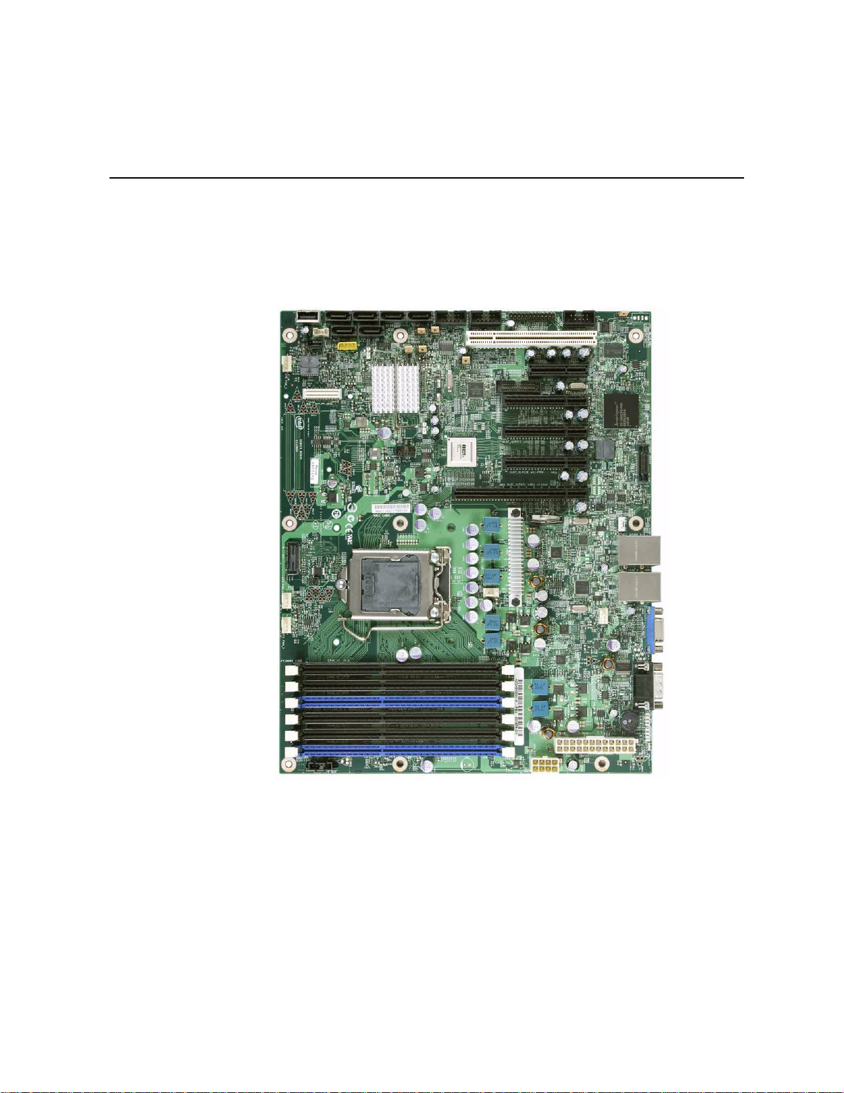
1 Server Board Features
This chapter briefly describes the main features of the Intel® Server Board S3420GP. This
chapter provides a photograph of the product, list of the server board features, and
diagrams showing the location of important components and connections on the server
board.
®
Figure 1. Intel
Intel® Server Board S3420GP User Guide 17
Server Board S3420GP
Page 20
Table 2 summarizes the features of the server board.
Table 2. Server Board Features
Feature Description
Processor Support for Intel
Series Processor or Intel
socket package.
®
Xeon® 3400 Series Processor, Intel® CoreTM i3
®
Pentium® G6950 in FC-LGA 1156
• 2.5 GT/s point-to-point DMI interface to PCH
• LGA 1156 pin socket
Memory Two memory channels with support for 1066/1333 MHz Unbuffered
(UDIMM) or ECC Registered (RDIMM) (Intel
only) DDR3.
®
• Intel
Server Board S3420GPLX and S3420GPLC:
– Up to two UDIMMs or three RDIMMs (Intel
Series only) per channel
®
Xeon® 3400 Series
®
Xeon® 3400
– 32 GB maximum with x8 ECC RDIMM (2 Gb DRAM) and 16
GB maximum with x8 ECC UDIMM (2 Gb DRAM)
®
• Intel
Server Board S3420GPV:
– Up to two UDIMMs per channel
– 16 GB maximum with x8 ECC UDIMM (2 Gb DRAM)
Chipset
• Intel
Server Board S3420GPLX:
– Support for Intel
®
3420 Platform Controller Hub (PCH)
®
– ServerEngines* LLC Pilot II BMC controller (Integrated
BMC)
– PCI Express* switch
®
• Intel
Server Board S3420GPLC:
– Support for Intel
(PCH)
®
3420 Chipset Platform Controller Hub
– ServerEngines* LLC Pilot II BMC controller (Integrated
BMC)
®
• Intel
Server Board S3420GPV:
– Support for Intel
(PCH)
®
3420 Chipset Platform Controller Hub
I/O Control External connections:
• DB-15 video connectors
• DB-9 serial Port A connector
• Four ports on two USB/LAN combo at rear of board.
Internal connections:
• Two USB 2x5 pin headers, each supporting two USB 2.0 ports
(Only one header for Intel
• One 2x5 Serial Port B connector (Intel
S3420GPLX and S3420GPLC)
®
Server board S3420GPV)
®
Server board
• Six SATA II connectors
• One SAS mezzanine slot supports for optional Intel® Remote
Management Module 3 (Intel
18 Intel® Server Board S3420GP User Guide
®
Server board S3420GPLX)
Page 21

Table 2. Server Board Features
Feature Description
Add-in PCI, PCI Express*
cards
• Intel
– Slot1: One 5-V PCI 32-bit / 33 MHz connector.
– Slot2: One PCI Express* Gen1 x4 (x1 throughput)
– Slot3: One PCI Express* Gen1 x8 (x4 throughput)
– Slot4: One PCI Express* Gen2 x8 (x4 throughput)
– Slot5: One PCI Express* Gen2x8 (x8 throughput)
– Slot6: One PCI Express* Gen2 x16 (x8 throughput)
• Intel
– Slot1: One 5-V PCI 32-bit / 33 MHz connector.
– Slot3: One PCI Express* Gen1 x8 (x4 throughput)
– Slot5: One PCI Express* Gen2 x8 (x8 throughput)
– Slot6: One PCI Express* Gen2 x16 (x8 throughput)
System Fan Support • Intel
Five 4-pin fan headers supporting four system fans and one
processor
• Intel
Four 4-pin fan headers supporting four system fans and one
processor
Video
• Intel
On-board ServerEngines* LLC Pilot II BMC Controller
– Integrated 2D Video Controller
– 64 MB DDR2 667 MHz Memory
• Intel
– Silicon Motion SM712GX04LF02-BA
®
Server Board S3420GPLX:
connector).
connector).
connector).
connector).
connector).
®
Server Board S3420GPLC/S3420GPV:
connector).
connector).
connector).
®
Server Board S3420GPLX/S3420GPLC
®
Server Board S3420GPV
®
Server Board S3420GPLX/S3420GPLC
®
Server Board S3420GPV
On-board Hard Drive Support for six Serial ATA II hard drives through six on-board SATA
II connectors with SW RAID 0, 1, 5, and 10.
®
• Intel
Intel® Server Board S3420GP User Guide 19
Server Board S3420GPLX:
– Up to four SAS hard drives through optional Intel
Entry RAID Module card
®
SAS
Page 22

Feature Description
RAID Support
Table 2. Server Board Features
®
• Intel
• Intel
Intel® Server Board S3420GPLX
• Intel
Embedded Server RAID Technology II through onboard
SATA connectors provides SATA RAID 0, 1, and 10.
®
Rapid Storage RAID through onboard SATA connectors
provides SATA RAID 0, 1, 5 and 10.
®
Embedded Server RAID Technology II through optional
®
Intel
SAS Entry RAID Module AXX4SASMOD provides SAS
RAID 0, 1, and 10 with optional RAID 5 support provided by the
Intel® RAID Activation Key AXXRAKSW5
• IT/IR RAID through optional Intel® SAS Entry RAID Module
AXX4SASMOD provides entry level hardware RAID 0, 1, 10,
and native SAS pass through mode
• 4 ports full featured SAS/SATA hardware RAID through
optional Intel® Integrated RAID Module SROMBSASMR
(AXXROMBSASMR), provides RAID 0, 1, 5, 6 and striping
capability for spans 10, 50, 60.
LAN One Gigabit Ethernet device 82574L connect to PCI-E x1 interfaces
Server Management Intel
on the PCH.
One Gigabit Ethernet PHY 82578DM connected to PCH through
PCI-E x1 interface
®
Server Board S3420GPLX/S3420GPLC:
On-board LLC Pilot II BMC Controller (iBMC)
• Integrated Baseboard Management Controller (Integrated
BMC), IPMI 2.0 compliant
• Integrated 2D video controller on PCI-E x1
®
• Intel
Server Board S3420GPLX:
– Remote Management Module III (RMM3)
20 Intel® Server Board S3420GP User Guide
Page 23

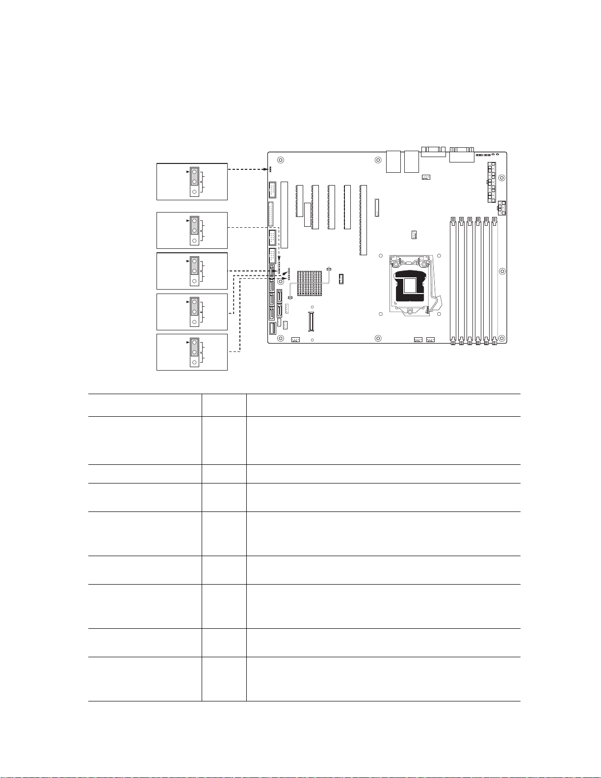
Connector and Header Locations
AF003290
CC
DD
ABCDEFGHIJ
K
LM
N
O
P
Q
R
S
T
U
V
W
X
Y
Z
AA
BB
A. Slot 1, 32 Mbit/33 MHz PCI Q. System FAN 2 and System
FAN 3
B. Slot 2, PCI Express* Gen1 x1
(x4 connector) (Intel
®
Server
R. CPU connector
Board S3420GPLX only)
C. Intel RMM3 Connector S. CPU Fan connector
D. Slot 3, PCI Express* Gen1 x4
T. USB SSD connector
(PCI Express* Gen2 compliant)
E. Slot 4, PCI Express* Gen2 x4
(x8 connector) (Intel
®
Server
Board S3420GPLX only)
Intel® Server Board S3420GP User Guide 21
U. SAS Module connector (Intel
Server Board S3420GPLX
only)
®
Page 24
F. Slot 5, PCI Express* Gen2 x8
(x8 connector)
V. System FAN 1 (Intel® Server
Board S3420GPLX and
S3420GPLC)
G. Slot 6, PCI Express* Gen2 x8
(x16 connector)
W. IPMB (Intel
S3420GPLX and S3420GPLC)
®
Server Board
H. CMOS battery X. SATA_SGPIO
I. Ethernet and Dual USB Combo Y. HSBP (Intel
®
S3420GPLX and S3420GPLC)
J. Ethernet and Dual USB Combo Z. USB Floppy
K. System FAN 4 AA. Six SATA ports
Server Board
L. Video port BB. Internal USB Connector (One
for Internal USB header on Intel
®
Server Board S3420GPV)
M. External serial port CC. Front panel connector
N. Main power connector DD. Internal serial ports
O. CPU power connector
P. DIMM slots (4 slots on Intel
®
Server Board S3420GPV)
Figure 2. Server Board Connector and Component Locations
22 Intel® Server Board S3420GP User Guide
Page 25
Configuration Jumpers
3
2
Default
CLEAR
CMOS
J1F5
CMOS
Clear
3
2
Default
Passwor d
Clear
J1F2
Password
Clear
3
2
Default
Recover
J1F3
BIOS
Recovery
3
2
Default
Enabled
J1F1
ME
Force
Update
3
2
Default
Enabled
J1A2
BMC
Force
Update
Jumper Name Pins What will occur during a system reset..
J1A2: BMC Force Update
®
(Intel
Server Board
1-2 BMC Firmware Force Update Mode — Disabled (Default)
S3420GPLX and
S3420GPLC)
2-3 BMC Firmware Force Update Mode — Enabled
J1F2: Password Clear 1-2 These pins should have a jumper in place for normal system
operation. (Default)
2-3 If these pins are jumpered, administrator and user passwords will
be cleared on the next reset.
NOTE: These pins should not be jumpered for normal operation.
J1F5: CMOS Clear 1-2 These pins should have a jumper in place for normal system
operation. (Default)
2-3 If these pins are jumpered, the CMOS settings are cleared on the
next reset.
J1F3: BIOS Recovery 1-2 These pins should have a jumper in place for normal system
NOTE: These pins should not be jumpered for normal operation.
operation. (Default)
2-3 The main system BIOS will not boot with th ese pins jumpered.
NOTE: The system will boot from EFI-bootable recovery media
with a recovery BIOS image.
Intel® Server Board S3420GP User Guide 23
Page 26
Jumper Name Pins What will occur during a system reset..
J1F1: ME Force Recov ery 1-2 These pins should have a jumper in place for normal system
operation. (Default)
2-3 ME force update mode
Figure 3. Configuration Jumpers Location
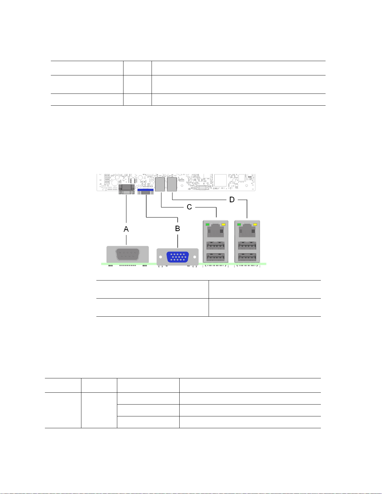
Back Panel Connectors
A. Serial Port A C. NIC Port 1 (1 Gb) and Dual USB Port
Connector
B. Video D. NIC Port 2 (1 Gb) and Dual USB Port
Connector
Figure 4. Back Panel Connectors
The NIC LEDs at the right and left of each NIC provide the following information.
Table 3. NIC LED Descriptions
NIC Color LED State Description
Left Green Off LAN link is not established.
On LAN link is established.
Blinking LAN activity is occurring.
24 Intel® Server Board S3420GP User Guide
Page 27
Table 3. NIC LED Descriptions
NIC Color LED State Description
Right N/A Off 10 Mbit/sec data rate is selected.
Green On 100 Mbit/sec data rate is selected.
Yellow On 1000 Mbit/sec data rate is selected.
RAID Support
The Intel® Server Board S3420GP provides an embedded SATA controller that supports
3.0 Gbps data transfer rates.
The BIOS Setup Utility provides drive configuration options on the Advanced | Mass
Storage Controller Configuration setup page, some of which affect the ability to configure
RAID. The on-board SATA Controller option is enabled by default and when enabled, you
can set the SATA Mode option to either one of the following four modes:
• Enhanced: Enhanced Mode supports up to six SATA ports with IDE native Mode.
• Compatibility: Supports up to four SATA ports [0/1/2/3] with IDE Legacy mode and
two SATA ports [4/5] with IDE Native Mode.
• AHCI: Supports all SATA ports using the Advanced Host Controller Interface
(AHCI).
• SW RAID: Intel
Technology is selected by the SW RAID mode. The Intel
Technology II feature provides RAID modes 0, 1, and 10. The Intel
Technology feature provides RAID modes 0, 1, 10, and 5.
Note: For help with navigating the BIOS Setup utility, see the Intel
Technical Product Specification.
For information on how to configure RAID, refer to the RAID software user's guide at:
http://www.intel.com/support/motherboards/server/S3420GP/howto.htm
®
Embedded Server RAID Technology II or Intel® Matrix Storage
Hardware Requirements
To avoid integration difficulties and possible board damage, your system must meet the
following requirements outlined. For a list of qualified components, see the links under
“Additional Information and Software”
®
Embedded Server RAID
®
Server Board S3420GP
®
Matrix Storage
Intel® Server Board S3420GP User Guide 25
Page 28

Processor
Memory
The Intel® Server Board S3420GP supports one Intel® Xeon® 3400 series with 95 W
Thermal Design Power (TDP) with 2.5 GT/s or one Intel
Thermal with 2.5 GT/s. At the same time, it also supports one Intel
®
Xeon® 3400 series with 65 W
®
i3® Processor®. For
a complete list of supported processors, see the links under “Additional Information and
Software”
The Intel®Server Board S3420GP supports a DDR3-based memory subsystem. The server
board supports up to three DIMM sockets per channel.
Refer to the following table for channel slot configuration. The minimal memory
population is one DIMM in memory slot DIMM_A1. For a complete list of supported
memory, see the links under “Additional Information and Software”.
Table 4. Channel Slot Configuration
Channel A Channel B
A1 A2 A3 B1 B2 B3
RDIMM X
UDIMM X
XX
XX X
XX
XX X
XX XX
XX XX
XX XXX
XX XXX X
XX
XX
XX X
XX XX
26 Intel® Server Board S3420GP User Guide
Page 29

The Independent Channel Mode is the default Maximum Performance Mode preferred for
®
Xeon® processor 3400 series based platforms. All two channels may be populated
Intel
in any order and have no matching requirements. All channels must run at the same
interface frequency, but individual channels may run at different DIMM timings, CAS
latency, and so forth).
Power Supply
A minimum of 350 W is required. Your supply must provide a minimum of 3 A of 5-V
standby current or the board will not boot.
Optional Hardware
Intel® SAS Entry RAID Module AXX4SASMOD
The Intel® Server Board S3420GPLX provides a SAS module slot (J2H1) for the
installation of an optional Intel
optional Intel
Express* links from PCI Express* x2 switch to the SAS module slot.
The optional Intel
controller that supports x4 PCI Express* link widths and is a single-function PCI
Express* end-point device. The SAS controller supports the SAS protocol as described in
the Serial Attached SCSI (SAS) Standard, version 1.0, and also supports SAS 1.1 features.
A 32-bit external memory bus off the SAS1064e controller provides an interface for Flash
ROM and NVSRAM (Nonvolatile Static Random Access Memory) devices.
The optional Intel
connectors that support up to four hard drives with a non-expander backplane or up to
eight hard drives with an expander backplane.
The optional Intel
(Serial General Purpose Input / Output) connector and a SCSI Enclosure Services (SES)
connector for backplane drive LED control.
®
SAS Entry RAID Module AXX4SASMOD is present, the x4 PCI
®
SAS Entry RAID Module AXX4SASMOD includes a SAS1064e
®
SAS Entry RAID Module AXX4SASMOD provides four SAS
®
SAS Entry RAID Module AXX4SASMOD also provides a SGPIO
®
SAS Entry RAID Module AXX4SASMOD. Once the
Intel® Server Board S3420GP User Guide 27
Page 30

SAS RAID Support
Figure 5. Intel® SAS Entry RAID Module
The BIOS Setup Utility provides drive configuration options on the Advanced | Mass
Storage Controller Configuration setup page for the Intel
AXX4SASMOD, some of which affect the ability to configure RAID.
The Intel
Entry RAID Module
AXX4SASMOD is present. When enabled, you can set the Configure Intel
RAID Module to either LSI* Integrated RAID or Intel
IT/IR RAID Mode
Supports entry hardware RAID 0, RAID 1, and RAID10/10E and native SAS pass
through mode.
When Intel
AXX4SASMOD, enclosure management is provided through the SAS_SGPIO or SES
connector on the SAS Module AXX4SASMOD when a cable is attached between this
connector and the backplane or I2C interface.
Note: For help with navigating the BIOS Setup utility, refer to the Intel
Technical Product Specification.
For information on how to configure RAID, see the RAID software user's guide at:
http://www.intel.com/support/motherboards/server/S3420GP/howto.htm
®
SAS Entry RAID Module
®
SAS Entry RAID Module option is enabled by default once the Intel® SAS
®
®
ESRTII mode.
®
Embedded Server RAID Technology II is enabled with the SAS Module
®
Server Board S3420GP
SAS Entry
For information about configure IT/IR RAID, see the IT/IR RAID software user's guide at:
http://www.intel.com/support/motherboards/server/S3420GP/howto.htm
28 Intel® Server Board S3420GP User Guide
Page 31

Intel® Management Module
The Intel® Remote Management Module 3 plugs into connectors on Intel® Server Board
S3420GPLX acts as components of the server board—not as separate products. You must
install these two components together.
These components provide a way to view and operate the server remotely in real time.
Keyboard, video, and mouse control (KVM) is redirected to a managing system; this
provides remote control of the server. USB media redirection allows you to use a USB
device anywhere on the network as if it was installed on the managed server.
For installation instructions for the Intel
instructions provided with the module.
®
The Intel
server board and acts as a component of the server board, and provides a way to view and
operate the server remotely in real-time. Keyboard, video, and mouse control (KVM) is
redirected to a managing system. This provides remote control. USB media redirection
allows you to use a USB device anywhere on the network as if it was installed on the
management server with RMM3 installed. For example, you can insert a CD-ROM disk in
a workstation CD-ROM drive and the managed server views it as its own, local CD-ROM
drive.
Remote Management Module 3 (RMM3) plugs into the connector on the
Intel® Local Control Panel
®
Remote Management Module 3, refer to the
The Intel® Local Control Panel provides enhanced system control by using a LCD
display, which provides additional controls and indicators beyond the standard control
panel.
Note: Use of this feature requires the installation of either the Intel
Advanced or Professional.
®
Management Module -
Intel® Server Board S3420GP User Guide 29
Page 32

30 Intel® Server Board S3420GP User Guide
Page 33

2 Server Utilities
Using the BIOS Setup Utility
This section describes the BIOS Setup Utility options, which is used to change server
configuration defaults. You can run BIOS Setup with or without an operating system
being present. See “Additional Information and Software” for a link to the Technical
Product Specification where you will find details about specific BIOS setup screens.
Starting Setup
You can enter and start BIOS Setup under several conditions:
• When you turn on the server, after POST completes the memory test.
• When you have moved the CMOS jumper on the server board to the "Clear CMOS"
position (enabled).
In the two conditions listed above, during the Power On Self Test (POST), you will see
this prompt:
Press <F2> to enter SETUP
In a third condition, when CMOS/NVRAM is corrupted, you will see other prompts but
not the <F2> prompt:
Warning: CMOS checksum invalid
Warning: CMOS time and date not set
In this condition, the BIOS will load default values for CMOS and attempt to boot.
If You Cannot Access Setup
If you cannot access the BIOS Setup, you might need to clear the CMOS memory. For
instructions on clearing the CMOS, see “Clearing the CMOS”.
Setup Menus
Each BIOS Setup menu page contains a number of features. Except for those features that
are provided only to display automatically configured information, each feature is
associated with a value field that contains user-selectable parameters. A user must have
adequate security rights to change these parameters. If a value cannot be changed for any
reason, the feature's value field is inaccessible.
Intel® Server Board S3420GP User Guide 31
Page 34

“Setup Menu Key Use” describes the keyboard commands you can use in the BIOS Setup
menus.
Table 5. Setup Menu Key Use
Key to Press Description
<F1> Pressing <F1> on any menu invokes the general help window.
Left and right arrows The left and right arrow keys are used to move between the major menu
pages. The keys have no effect if a submenu or pick list is displayed.
Up arrow Select Item up - The up arrow is used to select the previous value in a
menu item's option list, or a value field pick list. Pressing the <Enter>
key activates the selected item.
Down arrow Select Item down - The down arrow is used to select the next value in a
menu item's option list, or a value field pick list. Pressing the <Enter>
key activates the selected item.
<F5> or <-> Change Value - The minus key or the <F5> function key is used to
change the value of the current item to the previous value. This key
scrolls through the values in the associated pick list without displaying
the full list.
<F6> or <+> Change Value - The plus key or the <F6> function ke y is used to change
the value of the current menu item to the next value. This key scrolls
through the values in the associated pick list without displaying the full
list. On 106-key Japanese keyboards, the plus key has a different scan
code than the plus key on the other keyboard, but it has the same effect.
<Enter> Execute Command - The <Enter> key is used to activate submenus
when the selected feature is a submenu, or to display a pick list if a
selected feature ha s a v alue field, or to select a sub-fiel d f or multi- v alued
features like time and date. If a pick list is display ed, the <Enter> key will
undo the pick list, and allow another selection in the parent menu.
<Esc> Exit - The <Esc> key provides a mechanism for backing out of any field.
<F9> Setup Defaults - Pressing <F9> causes the following to display:
This key will undo the pressing of the <Enter> key. When the <Esc> key
is pressed while editing any field or selecting features of a menu, the
parent menu is re-entered. When the <Esc> key is pressed in any
submenu, the parent menu is re-entered. When the <Esc> key is
pressed in any major menu, the exit confirmation window is displayed
and the user is asked whether changes can be discarded.
Setup Confirmation
Load default configuration now?
[Yes] [No]
If "Yes" is selected and the <Enter> key is pressed, all Setup fields are
set to their default values. If "No" is selected and the <Enter> key is
pressed, or if the <Esc> key is pressed, the user is returned to where
they were before <F9> was pressed without affecting any existing field
values.
32 Intel® Server Board S3420GP User Guide
Page 35

Key to Press Description
<F10> Save and Exit - Pressing <F10> causes the following message to
Upgrading the BIOS
The upgrade utility allows you to upgrade the BIOS in flash memory. The code and data in
the upgrade file include the following:
• On-board system BIOS, including the recovery code, BIOS Setup Utility, and
strings.
• On-board video BIOS and other option ROMs for devices embedded on the server
board.
Table 5. Setup Menu Key Use
display:
Setup Confirmation
Save Configuration changes and exit now?
[Yes] [No]
If "Yes" is selected and the <Enter> key is pressed, all changes are
saved and Setup is exited. If "No" is selected and the <Enter> key is
pressed, or the <Esc> key is pressed, the user is returned to where they
were before <F10> was pressed without affecting any existing values.
• OEM binary area
• Microcode
Preparing for the Upgrade
The following steps explain how to prepare to upgrade the BIOS, including how to record
the current BIOS settings and how to obtain the upgrade utility.
Note: In the unlikely event a BIOS error occurs during the BIOS update process, you may need
to follow a recovery process to return the system to service. Refer to “Additional
Information and Software” for a link to necessary software and instructions.
Recording the Current BIOS Settings
1. Boot the computer and press <F2> when you see the message:
Press <F2> Key if you want to run SETUP
2. Write down the current settings in the BIOS Setup program.
Note: Do not skip step 2. You need these settings to configure your computer at the end of the
procedure.
Intel® Server Board S3420GP User Guide 33
Page 36

Obtaining the Upgrade
Download the BIOS image file to a temporary folder on your hard drive. Refer to
“Additional Information and Software” for a link to the update software.
Note: Before attempting a BIOS upgrade, review the instructions and release notes provided in
the readme file distributed with the BIOS image file. The release notes contain critical
information regarding jumper settings, specific fixes, or other information to complete the
upgrade.
Upgrading the BIOS
Follow the instructions in the readme file that came with the BIOS upgrade. When the
update completes, remove the bootable media from which you performed the upgrade.
Caution: Do not power down the system during the BIOS update process! The system resets
automatically when the BIOS update process is completed.
Note: You may encounter a CMOS Checksum error or other problem after reboot. If this
happens, shut down the system and reboot. CMOS checksum errors require that you enter
Setup, check your settings, save your settings, and exit Setup.
Recovering the BIOS
If an update to the system BIOS is not successful or if the system fails to complete POST
and the BIOS is unable to boot an operating system, it may be necessary to run the BIOS
recovery procedure.
To place the baseboard into recovery mode, move the boot option jumper (located on the
baseboard) to the recovery position. The BIOS can then execute the recovery BIOS (also
known as the boot block) instead of the normal BIOS. The recovery BIOS is a selfcontained image that exists solely as a fail-safe mechanism for installing a new BIOS
image.
Note: During the recovery mode, video is not initialized. One high-pitched beep announces the
start of the recovery process. The entire process takes two to four minutes. A successful
update ends with two high-pitched beeps. Failure is indicated by a long series of short
beeps.
34 Intel® Server Board S3420GP User Guide
Page 37
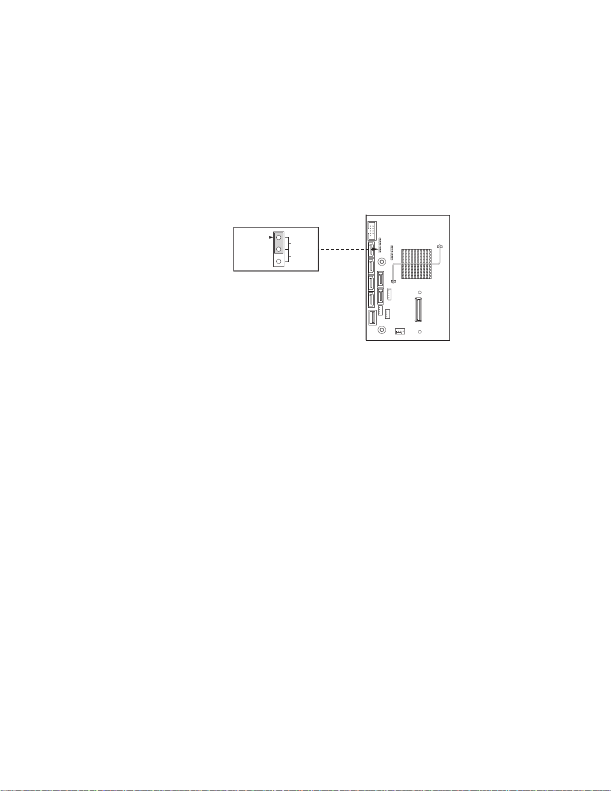
Recovering the BIOS
The following steps boot the recovery BIOS and flashes the normal BIOS:
1. Power down and unplug the system from the AC power source.
2. Move the recovery jumper at JIF3 from the spare location at pins 2 and 3 to cover
pins 1 and 2. Refer to the following figure.
BIOS
Recovery
J1F3
Default
2
Recover
3
AF003180
Figure 6. BIOS Recovery Jumper
3. Insert the bootable BIOS Recovery media containing the new BIOS image files. A
BIOS recovery can be accomplished from SATA CD and USB Mass Storage
device. Please note this platform does not support recovery from a USB floppy. The
recovery media must contain the following files under the root directory:
• FVMAIN.FV
• UEFI iFlash32
• *Rec.CAP
• Startup.nsh (update accordingly to use proper *Rec.CAP file)
4. Plug the system into the AC power source and power it on.
5. The BIOS POST screen will appear displaying the progress, and the system will
automatically boot to the EFI SHELL.
6. Remove the recovery media.
7. Power down and unplug the system from the AC power source.
8. Move the BIOS recovery jumper at J1F3 back to the original position, covering
storage pins 1 and 2.
9. Plug the system into the AC power source and power it up to confirm the recovery
was successful.
10. Do NOT interrupt the BIOS POST during the first boot.
Intel® Server Board S3420GP User Guide 35
Page 38
Clearing the Password
If the user or administrator password(s) is lost or forgotten, moving the password clear
jumper into the “clear” position clears both passwords. Before a new password(s) is set,
you must restore the password clear jumper to its original position.
1. Power down the system and disconnect the AC power.
2. Open the server chassis.
3. Move the jumper from the normal operation position, Password Clear Protect, at
pins 1 and 2 to the Password Clear Erase position, covering pins 2 and 3 as
indicated in the following diagram.
4. Reconnect the AC power, power up the system.
5. Power down the system and disconnect the AC power.
6. Return the Password Clear jumper to the Password Clear Protect position, covering
pins 1 and 2.
7. Reconnect the AC power and power up the server.
8. Close the server chassis. The password is cleared and can be reset by going into the
BIOS setup.
Clearing the CMOS
Password
Clear
J1F2
Default
2
Passwo rd
Clear
3
Figure 7. Password Recovery Jumper
AF003181
If you cannot access the BIOS setup screens, you must use the CMOS Clear jumper to
reset the configuration RAM.
1. Power down the system and disconnect the AC power.
2. Open the server chassis. For instructions, see your server chassis documentation.
36 Intel® Server Board S3420GP User Guide
Page 39

3. Move the jumper from the default operating position (covering pins 1 and 2) to the
3
2
Default
CLEAR
CMOS
J1F5
CMOS
Clear
AF003182
3
2
Default
Enabled
J1A2
BMC
Force
Update
AF003291
reset / clear position (covering pins 2 and 3).
Figure 8. CMOS Recovery Jumper
4. Wait five seconds.
5. Move the jumper back to default position, covering pins 1 and 2.
6. Close the server chassis.
7. Reconnect the AC power and power up the system. The CMOS is cleared and can
be reset by going into the BIOS setup.
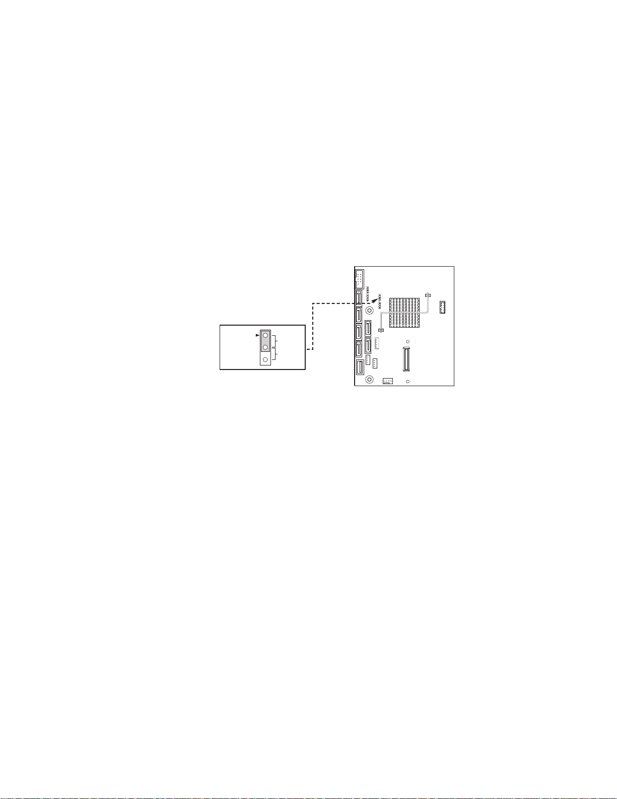
Updating the Integrated BMC (Intel® Server Board
S3420GPLX and S3420GPLC)
Figure 9. BMC Force Update Jumper
Intel® Server Board S3420GP User Guide 37
Page 40

When performing the standard Integrated BMC firmware update procedure, the update
utility places the Integrated BMC into an update mode, allowing the firmware to load
safely onto the flash device. In the unlikely event the Integrated BMC firmware update
process fails (due to the Integrated BMC not being in the proper update state), the server
board provides an Integrated BMC Force Update jumper, which forces the Integrated
BMC into the proper update state. You should complete the following procedure in the
event the standard Integrated BMC firmware update process fails.
Note: Normal Integrated BMC functionality is disabled with the Force Integrated BMC Update
jumper set to the enabled position. The server should never be run with the Integrated
BMC Force Update jumper set in this position. This jumper setting should only be used
when the standard firmware update process fails. This jumper should remain in the
default / disabled position when the server is running normally.
1. Power down and remove the AC power cord.
2. Open the server chassis. For instructions, refer to your server chassis
documentation.
3. Move the jumper from the default operating position (covering pins 1 and 2) to the
enabled position (covering pins 2 and 3).
4. Close the server chassis.
5. Reconnect the AC cord and power up the server.
6. Perform the Integrated BMC firmware update procedure as documented in the
README.TXT file included in the given Integrated BMC firmware update
package. After successful completion of the firmware update process, the firmware
update utility may generate an error stating the Integrated BMC is still in update
mode.
7. Power down and remove the AC power cord.
8. Open the server chassis.
9. Move jumper from the enabled position (covering pins 2 and 3) to the disabled
position (covering pins 1 and 2).
10. Close the server chassis.
11. Reconnect the AC cord and power up the server.
38 Intel® Server Board S3420GP User Guide
Page 41

3 Hardware Installations and
Upgrades
Before You Begin
Before working with your server product, pay close attention to the “Safety Information”
at the beginning of this manual.
Tools and Supplies Needed
• Phillips* (cross head) screwdriver (#1 bit and #2 bit)
• Needle nosed pliers
• A ruler
• Pen or pencil
• Antistatic wrist strap and conductive foam pad (recommended)
Installing and Removing Memory
The silkscreen on the board for the DIMMs displays DIMM_A1, DIMM_A2, DIMM_A3;
DIMM_B1, DIMM_B2, DIMM_B3 starting from the center of the board. DIMM_A1 is
one of two blue sockets which is close to the processor. For three slots per channel
configurations, the server board requires DDR3 DIMMs within a channel to be populated.
Installing DIMMs
To install DIMMs, follow these steps:
1. Observe the safety and ESD precautions in “Safety Information”.
2. Turn off all peripheral devices connected to the server. Turn off the server.
3. Disconnect the AC power cord from the server.
4. Remove the server's cover and locate the DIMM sockets (see letters “A” to “E”
Figure 10).
Intel® Server Board S3420GP User Guide 39
Page 42

5. Make sure the clips at either end of the DIMM socket(s) are pushed outward to the
open position (see letter “A” in Figure 10).
6. Holding the DIMM by the edges, remove it from its anti-static package.
7. Position the DIMM above the socket. Align the two small notches in the bottom
edge of the DIMM with the keys in the socket (letter “B” in Figure 10).
8. Insert the bottom edge of the DIMM into the socket (letter “C” in Figure 10).
9. When the DIMM is inserted, push down on the top edge of the DIMM until the
retaining clips snap into place ((letter “D” in Figure 10). Make sure the clips are
firmly in place (letter “E” in Figure 10).
10. Replace the server's cover and reconnect the AC power cord. Refer to the
documentation that came with your server chassis for instructions on installing the
server's cover.
Removing DIMMs
To remove a DIMM, follow these steps:
1. Observe the safety and ESD precautions in “Safety Information”.
Figure 10. Installing Memory
2. Turn off all peripheral devices connected to the server. Turn off the server.
3. Remove the AC power cord from the server.
4. Remove the server's cover. See the documentation that came with your server
chassis for instructions on removing the server's cover.
5. Gently spread the retaining clips at each end of the socket. The DIMM will lift from
the socket.
6. Holding the DIMM by the edges, lift it from the socket, and store it in an anti-static
package.
7. Reinstall and reconnect any parts you removed or disconnected to reach the DIMM
sockets.
40 Intel® Server Board S3420GP User Guide
Page 43

8. Replace the server's cover and reconnect the AC power cord. Refer to the
documentation that came with your server chassis for instructions on installing the
server's cover.
Installing or Replacing the Processor
Note: Use the following instructions to install or replace a processor instead of using the
instructions that came with the processor.
Caution: Processor must be appropriate: You may damage the server board if you install a
processor that is inappropriate for your server. See “Additional Information and
Software” for a link to the list of compatible processor(s).
Caution: ESD and handling processors: Reduce the risk of electrostatic discharge (ESD) damage to
the processor by doing the following: (1) Touch the metal chassis before touching the
processor or server board. Keep part of your body in contact with the metal chassis to
dissipate the static charge while handling the processor. (2) Avoid moving around
unnecessarily.
Installing the Processor
To install a processor, follow these instructions:
1. Observe the safety and ESD precautions in “Safety Information”.
2. Turn off all peripheral devices connected to the server. Turn off the server.
3. Disconnect the AC power cord from the server.
4. Remove the server's cover. See the documentation that came with your server
chassis for instructions on removing the server's cover.
Intel® Server Board S3420GP User Guide 41
Page 44

5. Locate the processor socket and open the socket lever (see Figure 11).
REMOVE
A
B
AF003186
Figure 11. Lifting the Load Lever
6. Open the load plate (see letter “A” and “B” in Figure 12).
A
REMOVE
B
REMOVE
AF003187
Figure 12. Open the Load Plate
42 Intel® Server Board S3420GP User Guide
Page 45

7. Remove the socket protective cover (Figure 13).
REMOVE
AF003188
Figure 13. Remove the Socket Protective Cover
8. Take the processor out of the box and remove the protective shipping cover
(Figure 14).
A
AF003189
Figure 14. Remove the Processor Protective Cover
9. Align the processor cutouts to match the two socket pins, and insert the processor
into the socket as shown in Figure 15.
Intel® Server Board S3420GP User Guide 43
Page 46

Figure 15. Installing the Processor
AF003190
A
AF003191
A
B
D
C
10. Close the load plate (see letter “A” in Figure 16), close the socket lever, and ensure
the load plate tab engages under the socket lever when fully closed (see letter “B”
and “C” in Figure 16).
Figure 16. Close the Load Plate and Socket Lever
44 Intel® Server Board S3420GP User Guide
Page 47

Note: Make sure the alignment triangle mark and the alignment triangle cutout align correctly.
Note: Heatsink
styles may vary
TIM
A
To assist in package orientation and alignment with the socket:
Installing the Heatsink(s)
1. If a protective film covers the thermal interface material (TIM) on the underside of
the heatsink, remove the protective film.
2. Align heatsink fins to the front and back of the chassis for correct airflow. Airflow
goes from front-to-back of chassis.
3. Each heatsink has four captive fasteners and should be tightened as shown.
4. Using a #2 Phillips* screwdriver, finger-tighten each fastener diagonally, according
to the white-circled numbers.
5. Securely re-tighten each fastener again in the same order as performed in Step 4.
6. Attach fan power cable to server board as shown.
Figure 17. 2U Reference Heatsink Assembly
7. Reinstall and reconnect any parts you removed or disconnected to reach the
Intel® Server Board S3420GP User Guide 45
processor sockets.
8. Replace the server's cover and reconnect the AC power cord. Refer to the
documentation that came with your server chassis for instructions on installing the
server's cover.
Page 48

Removing a Processor
1. Observe the safety and ESD precautions in “Safety Information”.
2. Turn off all peripheral devices connected to the server. Turn off the server.
3. Remove the AC power cord from the server.
4. Remove the server's cover. See the documentation that came with your server
chassis for instructions on removing the server's cover.
5. Unplug the processor fan cable from the server board.
6. Loosen the four captive screws on the corners of the heatsink.
7. Twist the heatsink slightly to break the seal between the heatsink and the processor.
8. Lift the heatsink from the processor. If it does not pull up easily, twist the heatsink
again. Do not force the heatsink from the processor. Doing so could damage the
processor.
9. Lift the processor lever.
10. Raise the CPU load plate.
11. Remove the processor.
12. If installing a replacement processor, see “Installing the Processor”. Otherwise,
install the protective socket cover over the empty processor socket and reinstall the
chassis cover.
Installing a PCI Card
This system does not include peripherals and add-in cards; you must purchase them
separately. The riser card at PCI slot 6 of the board supports a low-profile, half-length PCI
Express* add-in card. Refer to the SR1630GP/SR1630HGP System Service Guide for
more detailed information on how to install a PCI card.
Note: You must attach add-in cards to a riser card when the riser card is removed from the
chassis.
1. Remove the screw that attaches the PCI bracket shield to the rear of the chassis to
remove the shield. Retain the screw.
46 Intel® Server Board S3420GP User Guide
Page 49
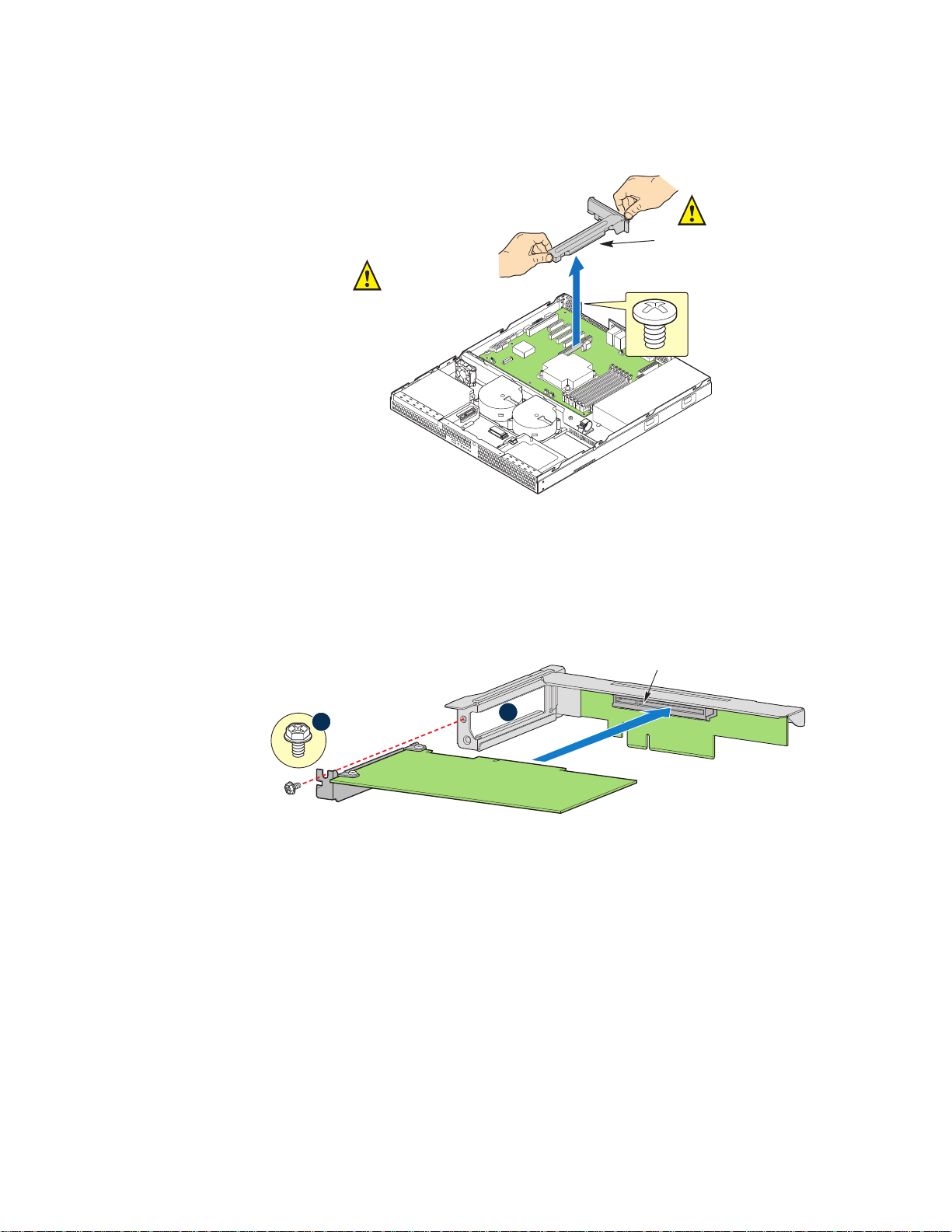
Figure 18. Removing the PCI Riser Assembly from the Server System
CAUTION:
Place the riser assembly
upsidedown to avoid
damage to the riser
card connector.
AF003193
Riser Card
Connector
Riser Connector
Riser Assembly
Supports one
PCIe* card.
Riser Card
A
B
Add-in Card
2. Insert the PCI card edge connector in the slot on the PCI riser.
Figure 19. Installing a PCI Card in a Riser Card
3. Insert the riser card with the attached PCI card into the PCI slot on the server board.
Press firmly on the riser card until it is fully seated. Press down on the riser card—
do NOT press down on the PCI card.
Caution: Press the riser card straight down into the slot. Tipping it in the slot while installing it may
damage the riser card or slot on the server board.
4. Use the screw removed in Step 1 to secure the riser card assembly to the chassis.
Intel® Server Board S3420GP User Guide 47
Page 50

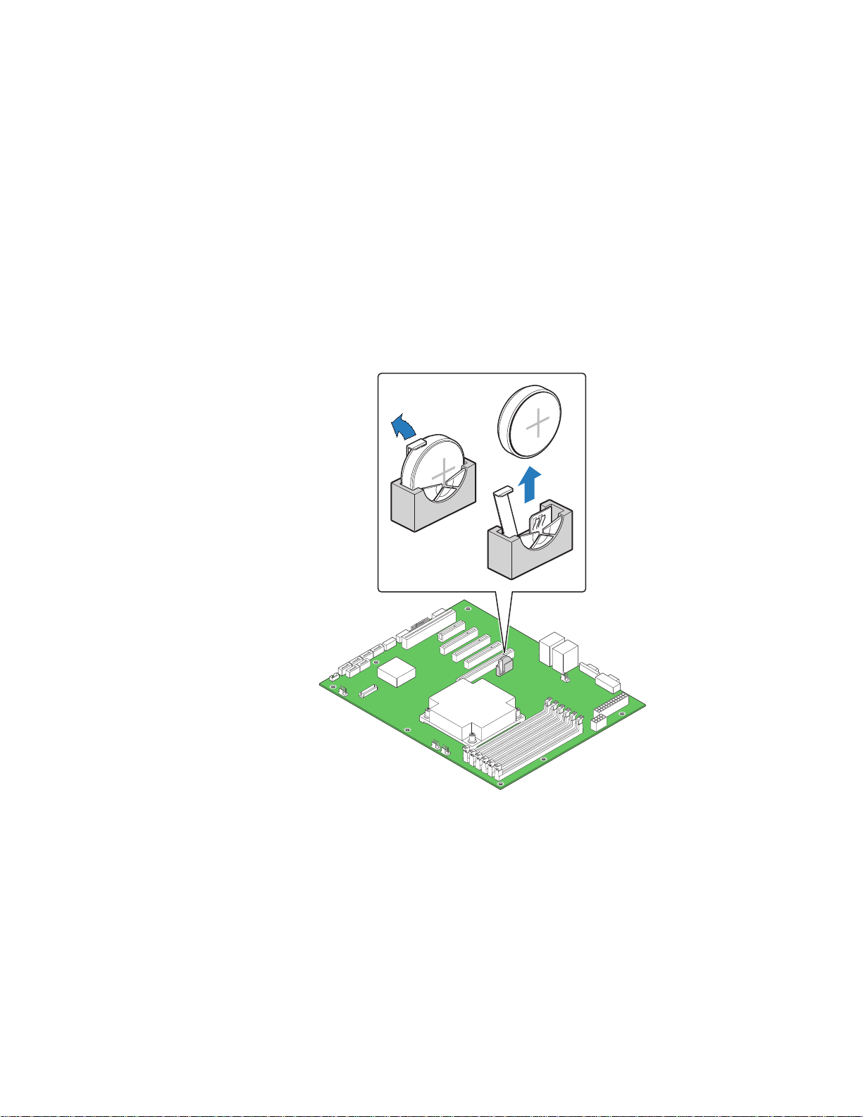
Replacing the Backup Battery
The lithium battery on the server board powers the RTC for up to 10 years in the absence
of power. When the battery starts to weaken, it loses voltage, and the server settings stored
in CMOS RAM in the RTC (for example, the date and time) may be wrong. Contact your
customer service representative or dealer for a list of approved devices.
Warni ng: Danger of explosion if battery is incorrectly replaced. Replace only with the same or
equivalent type recommended by the equipment manufacturer. Discard used batteries
according to manufacturer's instructions.
Advarsel: Lithiumbatteri - Eksplosionsfare ved fejlagtig håndtering. Udskiftning må kun ske med
batteri af samme fabrikat og type. Levér det brugte batteri tilbage til leverandøren.
Advarsel: Lithiumbatteri - Eksplosjonsfare. Ved utskifting benyttes kun batteri som anbefalt av
apparatfabrikanten. Brukt batteri returneres apparatleverandøren.
Va rn i ng : Explosionsfara vid felaktigt batteribyte. Använd samma batterityp eller en ekvivalent typ
som rekommenderas av apparattillverkaren. Kassera använt batteri enligt fabrikantens
instruktion.
Varoitus: Paristo voi räjähtää, jos se on virheellisesti asennettu. Vaihda paristo ainoastaan
laitevalmistajan suosittelemaan tyyppiin. Hävitä käytetty paristo valmistajan ohjeiden
mukaisesti.
48 Intel® Server Board S3420GP User Guide
Page 51
1. Observe the safety and ESD precautions in “Safety Information”.
2. Turn off all peripheral devices connected to the server. Turn off the server.
3. Disconnect the AC power cord from the server.
4. Remove the server's cover and locate the battery. See the documentation that came
with your server chassis for instructions on removing the server's cover.
5. Insert the tip of a small flat bladed screwdriver, or an equivalent, under the tab in
the plastic retainer. Gently push down on the screwdriver to lift the battery.
6. Remove the battery from its socket.
AF003185
Figure 20. Replacing the Backup Battery
7. Dispose of the battery according to local ordinance.
8. Remove the new lithium battery from its package, and, being careful to observe the
correct polarity, insert it in the battery socket.
9. Close the chassis.
10. Run Setup to restore the configuration settings to the RTC.
Intel® Server Board S3420GP User Guide 49
Page 52

50 Intel® Server Board S3420GP User Guide
Page 53
Appendix A: LED Decoder
During the system boot process, the BIOS executes a number of platform configuration
processes, each of which is assigned a specific hex POST code number. As each
configuration routine is started, the BIOS displays the POST code to the POST Code
Diagnostic LEDs on the back edge of the server board. To assist in troubleshooting a
system hang during the POST process, you can use the Diagnostic LEDs to identify the
last POST process executed.
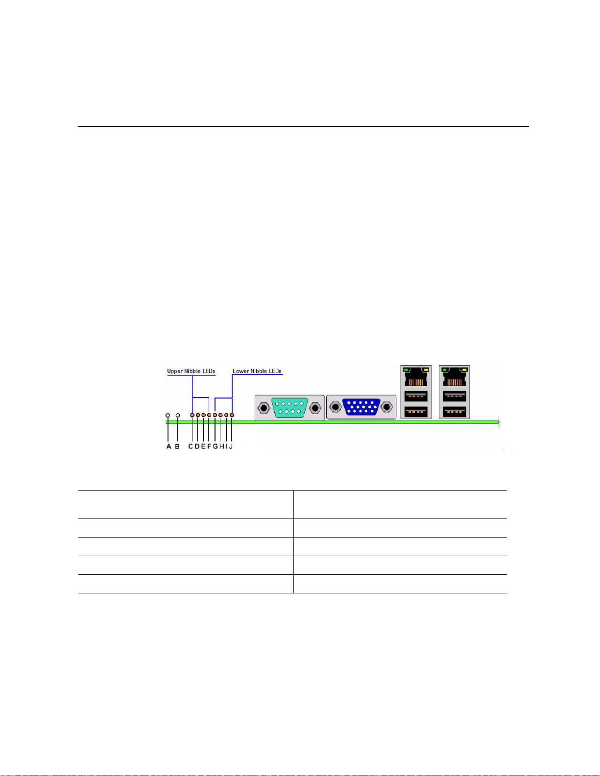
Each POST code is represented by the eight amber Diagnostic LEDs. The POST codes are
divided into two nibbles: an upper nibble and a lower nibble. The upper nibble bits are
represented by Diagnostic LEDs #4, #5, #6, and #7. The lower nibble bits are represented
by Diagnostics LEDs #0, #1, #2, and #3. Given the bit is set in the upper and lower
nibbles, the corresponding LED is lit. If the bit is clear, corresponding LED is off.
The Diagnostic LED #7 is labeled as MSB, and the Diagnostic LED #0 is labeled with
LSB.
A. ID LED B. Status LED (Intel® Server Board S3420GPLX
and S3420GPLC)
C. Diagnostic LED #7 (MSB LED) D. Diagnostic LED #6
E. Diagnostic LED #5 F. Diagnostic LED #4
G. Diagnostic LED #3 H. Diagnostic LED #2
I. Diagnostic LED #1 J. Diagnostic LED #0 (LSB LED)
Figure 21. Diagnostic LED Placement Diagram
In the following example, the BIOS sends a value of ACh to the diagnostic LED decoder.
The LEDs are decoded as follows:
Intel® Server Board S3420GP User Guide 51
Page 54
.
Table 6. POST Progress Code LED Example
LEDs Upper Nibble LEDs
MSB
LEDs
Status
Results
LED #7 LED #6 LED #5 LED #4 LED #3 LED #2 LED #1 LED #0
8h 4h 2h 1h 8h 4h 2h 1h
ON OFF ON OFF ON ON OFF OFF
10 1011 0 0
Ah Ch
Lower Nibble LEDs
• Upper nibble bits = 1010b = Ah; Lower nibble bits = 1100b = Ch; the two are
concatenated as ACh.
Table 7. Diagnostic LED POST Code Decoder
Diagnostic LED Decoder
Checkpoint O = On, X = Off Description
Upper Nibble Lower Nibble
MSB LSB
8h 4h 2h 1h 8h 4h 2h 1h
LED #7 #6#5 #4 #3#2#1#0
Host Processor
0x10h X XXO XXXXPower-on initialization of
the host processor
(bootstrap processor)
0x11h X XXO XXXOHost processor cache
initialization (including AP)
0x12h X X X O X X O X Starting application
processor initialization
0x13h X X X O X X O O SMM initialization
Chipset
0x21h X XOX XXXOInitializing a chipset
component
Memory
52 Intel® Server Board S3420GP User Guide
Page 55

Table 7. Diagnostic LED POST Code Decoder
0x22h X X O X X X O X Reading configuration
data from memory (SPD
on FBDIMM)
0x23h X X O X X X O O Detecting presence of
0x24h X X O X X O X X Programming timing
0x25h X X O X X O X O Configuring memory
0x26h X X O X X O O X Optimizing memory
0x27h X XOX XOOOInitializing memory, such
0x28h X XOX XXXXTesting memory
memory
parameters in the memory
controller
parameters in the memory
controller
controller settings
as ECC init
Intel® Server Board S3420GP User Guide 53
Page 56
Table 7. Diagnostic LED POST Code Decoder
PCI Bus
0x50h X OXO XXXXEnumerating PCI buses
0x51h X OXO XXXOAllocating resources to
PCI buses
0x52h X O X O X X O X Hot Plug PCI controller
initialization
0x53h X O X O X X O O Reserved for PCI bus
0x54h X O X O X O X X Reserved for PCI bus
0x55h X O X O X O X O Reserved for PCI bus
0x56h X O X O X O O X Reserved for PCI bus
0x57h X OXO XOOOReserved for PCI bus
USB
0x58h X OXO OXXXResetting USB bus
0x59h X O X O O X X O Reserved for USB devices
ATA / ATAPI / SATA
0x5A X O X O O X O X Resetting SATA bus and
0x5B X O X O O X O O Reserved for ATA
0x5C X O X O O O X X Enable Smart if supported
0x5D X O X O O O X O Reserved for ATA
SMBUS
0x5E X OXO OOOXResetting SMBUS
0x5F X OXO OOOOReserved for SMBUS
Local Console
0x70h X OOO XXXXResetting the video
0x71h X OOO XXXODisabling the video
0x72h X O O O X X O X Enabling the video
Remote Console
0x78 X OOO OXXXResetting the console
all devices
by ATA device
controller (VGA)
controller (VGA)
controller (VGA)
controller
0x79 X O O O O X X O Disabling the console
54 Intel® Server Board S3420GP User Guide
controller
Page 57
Table 7. Diagnostic LED POST Code Decoder
0x7A X O O O O X O X Enabling the console
controller
Keyboard (only USB) / Keyboard (PS/2 or USB)
0x90 O XXO XXXXResetting the keyboard
0x91 O XXO XXXODisabling the keyboard
0x92 O X X O X X O X Detecting the presence of
the keyboard
0x93 O X X O X X O O Enabling the keyboard
0x94 O X X O X O X X Clearing keyboard input
buffer
0x95 O XXO XOXOInstructing keyboard to
run Self Test (PS/2 only)
Mouse (only USB) / Mouse (PS/2 or USB)
0x98 O XXO O XXXResetting the mouse
0x99 O XXO O XXODetecting the mouse
0x9A O X X O O X O X Detecting the presence of
0x9B O X X O O X O O Enabling the mouse
Fixed Media
0xB0 O XOO XXXXResetting fixed media
0xB1 O XOO XXXODisabling fixed media
0xB2 O X O O X X O X Detecting the presence of
0xB3 O X O O X X O O Enabling / configuring a
Removable Media
0xB8 O XOO OXXXResetting the removable
0xB9 O X O O O X X O Disabling the removable
0xBA O X O O O X O X Detecting the presence of
mouse
device
device
a fixed media device (hard
drive detection, and so on)
fixed media device
media device
media device
a removable media device
(CD-ROM detection, etc.)
0xBC O X O O O O X X E nabling / configuring a
removable media device
Intel® Server Board S3420GP User Guide 55
Page 58

Table 7. Diagnostic LED POST Code Decoder
Boot Device Selection (BDS)
0xD0 O OXO XXXXTrying boot selection
0xD1 O OXO XXXOTrying boot selection
0xD2 O O X O X X O X Trying boot selection
0xD3 O O X O X X O O Trying boot selection
0xD4 O O X O X O X X Trying boot selection
0xD5 O O X O X O X O Trying boot selectiont
0xD6 O O X O X O O X Trying boot selection
0xD7 O OXO XOOOTrying boot selection
0xD8 O OXO OXXXTrying boot selection
0xD9 O O X O O X X O Trying boot selection
0xDA O O X O O X O X Trying boot selection
0xDB O O X O O X O O Trying boot selection
0xDC O O X O O O X X Trying boot selection
0xDD O O X O O O X O Trying boot selection
0xDE O OXO OOOXTrying boot selection
0xDF O OXO OOOOTrying boot selection
Pre-EFI Initialization (PEI) Core
0xE0 O OOX OXXXStarted dispatching early
0xE1 O OOX XXXOReserved for initialization
0xE2 O O O X X X O X Initial memory found,
0xE3 O O O X X X O O Reserved for initialization
Driver Execution Environment (DXE) Core (not accompanied by a beep code)
0xE4 O OOX OXXXEntered EFI driver
0xE5 O O O X O X X O Started dispatching
0xE6 O O O X O X O X Started connecting drivers
DXE Drivers (not accompanied by a beep code)
initialization modules
(PEIM)
module ues (PEIM)
configured, and installed
correctly
module ues (PEIM)
execution phase (DXE)
drivers
56 Intel® Server Board S3420GP User Guide
Page 59

Table 7. Diagnostic LED POST Code Decoder
0xE7 O OOX XOOOWaiting for user input
0xE8 O OOX OXXXChecking password
0xE9 O OOX OXXOEntering BIOS setup
0xEA O OOX OXOXFlash Update
0xEE O OOX OOOXCalling Int 19. One beep
unless silent boot is
enabled.
0xEF O OOX OOOOUnrecoverable boot failure
Runtime Phase / EFI Operating System Boot
0xF2 O O O O X X O X Signal that the operating
0xF4 O O O O X O X X Entering Sleep state
0xF5 O O O O X O X O Exiting Sleep state
0xF8 O OOO OXXXOperating system has
0xF9 O O O O O X X O Operating system has
0xFAh\ O O O O O X O X Operating system has
Pre-EFI Initialization Module (PEIM) / Recovery
0x30 X XOO XXXXCrisis recovery has been
system has switched to
virtual memory mode.
requested EFI to close
boot services
(ExitBootServices ( ) has
been called)
switched to virtual
address mode
(SetVirtualAddressMap ( )
has been called)
requested the system to
reset (ResetSystem () has
been called)
initiated because of a user
request
0x31 X XOO XXXOCrisis recovery has been
initiated by software
(corrupt flash)
0x34 X XOO XOXXLoading crisis recovery
capsule
0x35 X X O O X O X O Handing off control to the
0x3F X XOO OOOOUnable to complete crisis
Intel® Server Board S3420GP User Guide 57
crisis recovery capsule
recovery
Page 60

Table 7. Diagnostic LED POST Code Decoder
Memory Error Codes (Accompanied by a beep code)
0xE8h O OOX OXXXNo Usable Memory Error:
No memory in the system,
or SPD data bad so no
memory could be
detected.
0xEBh O OOX OXOOMemory Test Error:
Memory failed Hardware
BIST.
0xEDh O OOX OOXOPopulation Error: RDIMMs
and UDIMMs cannot be
mixed in the system.
0xEEh O OOX OOOXMismatch Error: More
than two Quad-Ranked
DIMMS in a channel.
58 Intel® Server Board S3420GP User Guide
Page 61

Appendix B: Intel® Server Issue Report
Form
Issue Report Form (Rev 3.6)
Note: Filling out this form completely is required for any escalation.
===============================================================
Customer Contact Information:
Customer Support Case #:
===============================================================
Intel® Server Board or System:
(Example: S3420GPLX or SR1630GP)
===============================================================
Server Chassis:
(Example SC5400. If third-party chassis used, indicate make and model.)
===============================================================
Baseboard Information: (some information maybe found by
accessing BIOS & going through the Server Management menu ->
System Information)
Baseboard PBA/TA/AA # (Example: 123456-789):
- can be found on the white sticker label on the baseboard
System BIOS Version:
®
Remote Management Module Firmware Version (if applicable):
Intel
®
Management Module BMC Revision (if applicable):
Intel
BMC/mBMC Version:
FRU/SDR Version:
HSC Version:
Has the latest BIOS been tried? (Yes/No):
Intel® Server Board S3420GP User Guide 59
Page 62

Processor 1
Processor 2
Processor 3
Processor 4
Has the latest BMC/mBMC been tried? (Yes/No):
Has the latest IMM BMC been tried? (Yes/No):
Has the latest RMM Firmware been tried? (Yes/No):
Has the latest FRU/SDR been tried? (Yes/No):
Has the latest HSC been tried? (Yes/No):
===============================================================
Processor information:
Type Speed sSpec Thermal Solution
Thermal solution (Heatsink) examples:
(1U, Passive w/air ducting, Active w/fan, etc.)
===============================================================
Memory:
Manufacturer Part Number DRAM Part Number On Intel tested list?
60 Intel® Server Board S3420GP User Guide
Page 63

Add-in adapters (Example: NICs, Management Adapters, Serial
Expansion Cards, PCI-Express* Adapters, RAID Controllers,
SCSI Controllers, etc.):
Type Slot Manufacturer Model Firmware
Third party hardware (Example: KVM, Chassis, etc.):
Description/Use Manufacturer Model Firmware
Storage Devices (Example: SCSI, SATA, SAS, USB, Tape, etc.):
Manufacturer Model Type Size Firmware
===============================================================
Operating System Information (Example: RedHat* Enterprise
Linux, Microsoft* Windows* Server 2003, Service pack 1, OEM
CD):
Manufacturer:
Ve r s io n :
Language version (English, Arabic, Chinese (Simplified)):
Service Pack Level or Kernel Revision:
In Hot-Swap
Bay?
Distribution (OEM/Retail):
===============================================================
Intel® Server Board S3420GP User Guide 61
Page 64

Intel® RAID Controller: (Example SRCU42E)
RAID controller part number (PBA number):
RAID controller firmware version:
Has the latest RAID firmware been tried? (Yes/No):
RAID driver version:
Has the latest RAID driver been tried? (Yes/No):
RAID volumes configuration (disks & RAID level):
RAID volume use (Boot device/Data Volume):
Is BBU (Battery Backup Unit) installed? (Yes/No):
BBU part number:
===============================================================
Detailed description of issue:
Troubleshooting tried:
62 Intel® Server Board S3420GP User Guide
Page 65

Steps to replicate the issue:
===============================================================
Issue impact statements:
Do you have any potential Intel system, or component purchases that this issue is
holding up? If yes, please provide a brief description below.
Do you have systems already purchased that are not being delivered to your
customers because of this issue? If yes, please provide a brief description below.
Have you returned systems or components to your place of purchase because of this
issue? If yes, please provide a brief description below.
*All other brands and names are property of their respective owners.
Intel® Server Board S3420GP User Guide 63
Page 66

64 Intel® Server Board S3420GP User Guide
Page 67

Appendix C: Getting Help
If you encounter an issue with your server system, follow these steps to obtain support:
1. Visit the following Intel support web page:
http://support.intel.com/support/motherboards/server
This web page provides 24x7 support when you need it to get the latest and most
complete technical support information on all Intel Enterprise Server and Storage
Platforms. Information available at the support site includes:
— Latest BIOS, firmware, drivers and utilities
— Product documentation, installation and quick start guides
— Full product specifications, technical advisories and errata
— Compatibility documentation for memory, hardware add-in cards, chassis
support matrix and operating systems
— Server and chassis accessory parts list for ordering upgrades or spare parts
— A searchable knowledgebase to search for product information throughout the
support site
2. If you are still unable to obtain a solution to your issue, send an email to Intel’s
technical support center using the online form available at
http://supportmail.intel.com/scripts-emf/welcome.aspx
3. Lastly, you can contact an Intel support representative using one of the support
phone numbers available at http://support.intel.com/support/9089.htm
(charges may apply). Intel customer support suggests filling out the issue report
form available at “Intel
issue.
Intel also offers Channel Program members around-the-clock 24x7 technical phone
support on Intel
®
Server Management at http://www.intel.com/reseller/.
Intel
Note: You will need to log in to the Reseller site to obtain the 24x7 number.
®
server boards, server chassis, server RAID controller cards, and
Warranty Information
To obtain warranty information, visit the following Intel web site:
http://support.intel.com/support/motherboards/server/sb/CS-010807.htm
®
Server Issue Report Form” on page 59 to better service the
Intel® Server Board S3420GP User Guide 65
Page 68

66 Intel® Server Board S3420GP User Guide
Page 69

Appendix D: Regulatory and Compliance
Information
Product Regulatory Compliance
Product Safety Compliance
The Intel® Server Board S3420GP complies with the following safety requirements:
• UL60950-1 - CSA 60950-1 (USA / Canada)
• EN60950-1 (Europe)
• IEC60950-1 (International)
• CB Certificate & Report, IEC60950-1 (report to include all country national
deviations)
• Belarus License - Listed on System License (Belarus)
• CE - Low Voltage Directive 73/23/EEE (Europe)
• IRAM Certification (Argentina)
Product EMC Compliance - Class A Compliance
Note: Legally this product is required to comply with Class A emission requirements because it
is intended for a commercial type market place. Intel targets 10db margin to Class A
Limits.
®
The Intel
following electromagnetic compatibility (EMC) regulations when installed a compatible
Intel
Builder Web site or contact your local Intel representative.
• FCC / ICES-003 - Emissions (USA/Canada) Verification
• CISPR 22 - Emissions (International)
• EN55022 - Emissions (Europe)
• EN55024 - Immunity (Europe)
• CE - EMC Directive 2004/108/EC (Europe)
• VCCI Emissions (Japan)
• AS/NZS CISPR 22 Emissions (Australia / New Zealand)
• BSMI CNS13438 Emissions (Taiwan)
Server Board S3420GP been has been tested and verified to comply with the
®
host system. For information on compatible host system(s) see Intel's Server
Intel® Server Board S3420GP User Guide 67
Page 70
• Belarus License - Listed on one System License (Belarus)
• RRL MIC Notice No. 1997-41 (EMC) & 1997-42 (EMI) (Korea)
Certifications / Registrations / Declarations
• UL Certification (US/Canada)
• CE Declaration of Conformity (CENELEC Europe)
• FCC/ICES-003 Class A Attestation (USA/Canada)
• C-Tick Declaration of Conformity (Australia)
• MED Declaration of Conformity (New Zealand)
• BSMI Certification (Taiwan)
• Belarus - Listed on one System License (Belarus)
• RRL Certification (Korea)
• Ecology Declaration (International)
Product Regulatory Compliance Markings
This product is marked with the following Product Certification Markings:
Table 8. Product Certification Markings
Regulatory
Compliance
UL Mark USA/Canada
CE Mark Europe
EMC Marking (Class A) Canada CANADA ICES-003 CLASS A
Region Marking
CANADA NMB-003 CLASSE A
68 Intel® Server Board S3420GP User Guide
Page 71
Table 8. Product Certification Markings
Regulatory
Compliance
BSMI Marking (Class A) Taiwan
Ctick Marking Australia / New Zealand
RLL MIC Mark Korea
Region Marking
N232
See the regulatory information document for additional
information.
Recycling Package Mark China
Recycling Package Mark Other than China
Intel® Server Board S3420GP User Guide 69
Page 72
Table 8. Product Certification Markings
Regulatory
Compliance
RoHS China
Region Marking
Electromagnetic Compatibility Notices
FCC (USA)
This device complies with Part 15 of the FCC Rules. Operation is subject to the following
two conditions: (1) this device may not cause harmful interference, and (2) this device
must accept any interference received, including interference that may cause undesired
operation.
For questions related to the EMC performance of this product, contact:
Intel Corporation
5200 N.E. Elam Young Parkway
Hillsboro, OR 97124-6497
1-800-628-8686
This equipment has been tested and found to comply with the limits for a Class A digital
device, pursuant to Part 15 of the FCC Rules. These limits are designed to provide
reasonable protection against harmful interference in a residential installation. This
equipment generates, uses, and can radiate radio frequency energy and, if not installed and
used in accordance with the instructions, may cause harmful interference to radio
communications. However, there is no guarantee that interference will not occur in a
particular installation. If this equipment does cause harmful interference to radio or
television reception, which can be determined by turning the equipment off and on, the
user is encouraged to try to correct the interference by one or more of the following
measures:
• Reorient or relocate the receiving antenna.
• Increase the separation between the equipment and the receiver.
• Connect the equipment to an outlet on a circuit other than the one to which the
receiver is connected.
• Consult the dealer or an experienced radio/TV technician for help.
Any changes or modifications not expressly approved by the grantee of this device could
void the user's authority to operate the equipment. The customer is responsible for
ensuring compliance of the modified product.
70 Intel® Server Board S3420GP User Guide
Page 73
Only peripherals (computer input/output devices, terminals, printers, etc.) that comply
with FCC Class A or B limits may be attached to this computer product. Operation with
noncompliant peripherals is likely to result in interference to radio and TV reception.
All cables used to connect to peripherals must be shielded and grounded. Operation with
cables, connected to peripherals, that are not shielded and grounded may result in
interference to radio and TV reception.
ICES-003 (Canada)
Cet appareil numérique respecte les limites bruits radioélectriques applicables aux
appareils numériques de Classe A prescrites dans la norme sur le matériel brouilleur:
“Apparelis Numériques”, NMB-003 édictee par le Ministre Canadian des
Communications.
This digital apparatus does not exceed the Class A limits for radio noise emissions from
digital apparatus set out in the interference-causing equipment standard entitled: “Digital
Apparatus,” ICES-003 of the Canadian Department of Communications.
Europe (CE Declaration of Conformity)
This product has been tested in accordance too, and complies with the Low Voltage
Directive (73/23/EEC) and EMC Directive (89/336/EEC). The product has been marked
with the CE Mark to illustrate its compliance.
VCCI (Japan)
English translation of the notice above:
This is a Class B product based on the standard of the Voluntary Control Council for
Interference (VCCI) from Information Technology Equipment. If this is used near a radio
or television receiver in a domestic environment, it may cause radio interference. Install
and use the equipment according to the instruction manual.
Intel® Server Board S3420GP User Guide 71
Page 74

BSMI (Taiwan)
The BSMI Certification Marking and EMC warning is located on the outside rear area of
the product.
RRL (Korea)
English translation of the notice above:
1. Type of Equipment (Model Name): On License and Product
2. Certification No.: On RRL certificate. Obtain certificate from local Intel
representative
3. Name of Certification Recipient: Intel Corporation
4. Date of Manufacturer: Refer to date code on product
5. Manufacturer/Nation: Intel Corporation/Refer to country of origin marked on
product
Restriction of Hazardous Substances (RoHS) Compliance
Intel has a system in place to restrict the use of banned substances in accordance with the
European Directive 2002/95/EC. Compliance is based on declaration that materials
banned in the RoHS Directive are either (1) below all applicable threshold limits or (2) an
approved / pending RoHS exemption applies.
72 Intel® Server Board S3420GP User Guide
Page 75

RoHS implementation details are not fully defined and may change.
Threshold limits and banned substances are noted below:
• Quantity limit of 0.1% by mass (1000 PPM) for:
—Lead
—Mercury
— Hexavalent Chromium
— Polybrominated Biphenyls Diphenyl Ethers (PBDE)
• Quantity limit of 0.01% by mass (100 PPM) for:
—Cadmium
End-of-Life / Product Recycling
Product recycling and end-of-life take-back systems and requirements vary by country.
Contact the retailer or distributor of this product for information about product recycling
and / or take-back.
Intel® Server Board S3420GP User Guide 73
Page 76

74 Intel® Server Board S3420GP User Guide
Page 77

Appendix E: Troubleshooting
This chapter helps you identify and solve problems that might occur while you are using
the system.
For any issue, first ensure you are using the latest firmware and files. Firmware upgrades
include updates for BIOS, the baseboard management controller (BMC), and the hot-swap
controller (HSC). See “Additional Information and Software” for a link to the software
updates. In addition to the server firmware and files, also update any drivers used for
components you installed in your system, such as video drivers, network drivers, and
SCSI drivers.
Intel provides a package called the "Platform Confidence Test" that may help with your
diagnostics. See “Additional Information and Software” for a link to this software.
If you cannot resolve your server problems on your own, see “Getting Help” for
assistance.
System Boot Quiet Time
The power-on self test (POST) process includes a quiet time, during which the system
may appear to be hung. This may last as long as 20 seconds. Do not power off or reboot
the system during this time. The POST LEDs will indicate activity-they may alternate
blinking between amber and green. When the quiet time completes, the status LED will
change to solid green.
Resetting the System
Before going through in-depth troubleshooting, attempt first to perform reset your system
using one of the methods below.
Soft boot reset to clear the system memory and reload the operating
system
Clear system memory, restart POST, and reload the operating system Reset button
Cold boot reset. Turn the system power off and then on. This clears
system memory, restarts POST, reloads the operating system, and halts
power to all peripherals
Table 9. Resetting the System
To do this Pre s s
<Ctrl+Alt+Del>
Power off/on
button
Intel® Server Board S3420GP User Guide 75
Page 78

Problems following Initial System Installation
Problems that occur at initial system startup are usually caused by an incorrect installation
or configuration. Hardware failure is a less frequent cause. If the problem you are
experiencing is with a specific software application, see “Problems with Newly Installed
Application Software”.
First Steps Checklist
• Is AC power available at the wall outlet?
• Are the power supplies plugged in? Check the AC cable(s) on the back of the chassis
and at the AC source.
• Are all cables correctly connected and secured?
• Are the processors fully seated in their sockets on the server board?
• Are all standoffs in the proper location and not touching any components, causing a
potential short?
• Are all add-in PCI boards fully seated in their slots on the server board?
• Are all jumper settings on the server board correct?
• Are all jumper and switch settings on add-in boards and peripheral devices correct?
To check these settings, refer to the manufacturer's documentation that comes with
them. If applicable, ensure that there are no conflicts-for example, two add-in boards
sharing the same interrupt.
• Are all peripheral devices installed correctly?
• If the system has a hard disk drive, is it properly formatted or configured?
• Are all device drivers properly installed?
• Are the configuration settings made in Setup correct?
• Is the operating system properly loaded? See the operating system documentation.
• Did you press the system power on/off switch on the front panel to turn the server on
(power on light should be lit)?
• Is the system power cord properly connected to the system and plugged into a
NEMA 5 15R outlet for 100-120 V or a NEMA 6-15R outlet for 200-240 V?
• Are all integrated components from the tested components lists? Check the tested
memory, and chassis lists, as well as the supported hardware and operating system
list. See “Additional Information and Software” for links to the tested component
lists.
76 Intel® Server Board S3420GP User Guide
Page 79

Hardware Diagnostic Testing
This section provides a more detailed approach to identifying a hardware problem and
locating its source.
Caution: Turn off devices before disconnecting cables: Before disconnecting any peripheral cables
from the system, turn off the system and any external peripheral devices. Failure to do so
can cause permanent damage to the system and/or the peripheral devices.
1. Turn off the system and all external peripheral devices. Disconnect each device
from the system, except for the keyboard and the video monitor.
2. Make sure the system power cord is plugged into a properly grounded AC outlet.
3. Make sure your video display monitor and keyboard are correctly connected to the
system. Turn on the video monitor. Set its brightness and contrast controls to at
least two thirds of their maximum ranges (refer to the documentation supplied with
your video display monitor).
4. If the operating system normally loads from the hard disk drive, make sure there is
no diskette in drive A and no CD-ROM disk in the CD-ROM drive.
5. If the power LED does light, attempt to boot from a floppy diskette or from a CDROM disk.
6. Turn on the system. If the power LED does not light, see “Power Light Does Not
Light”.
Verifying Proper Operation of Key System Lights
As POST determines the system configuration, it tests for the presence of each mass
storage device installed in the system. As each device is checked, its activity light should
turn on briefly. Check for the following:
• Does the diskette drive activity light turn on briefly? If not, see “Drive Activity
Light Does Not Light”.
• If system LEDs are illuminated, see “Make sure the BIOS is configured to allow the
CD-ROM to be the first bootable device.” for a description of the light and steps to
take to correct the problem.
Confirming Loading of the Operating System
Once the system boots up, the operating system prompt displays on the screen. The
prompt varies according to the operating system. If the operating system prompt does not
display, see “No Characters Display on Screen”.
Intel® Server Board S3420GP User Guide 77
Page 80

Specific Problems and Corrective Actions
This section provides possible solutions for these specific problems:
• Power light does not light.
• No characters appear on screen.
• Characters on the screen appear distorted or incorrect.
• System cooling fans do not rotate.
• Hard disk drive activity light does not light.
• Optical drive activity light does not light.
• There are problems with application software.
• The bootable CD-ROM is not detected.
Try the following solutions in the order given. If you cannot correct the problem, contact
your service representative or authorized dealer for help.
Power Light Does Not Light
Check the following:
• Did you press the power-on button?
• Is the system operating normally? If so, the power LED might be defective or the
cable from the control panel to the server board might be loose.
• Have you securely plugged the server AC power cord into the power supply?
• Some ATX power supplies have a power switch on the back of the power supply,
next to the fan. If your system has one, is it turned on?
• Remove all add-in cards and see if the system boots. If successful, add the cards
back in one at a time with a reboot between each addition.
• Make sure the memory DIMMs comply with the system requirements.
• Make sure the memory DIMMs were populated according to the system
requirements.
• Remove the memory DIMMs and re-seat them.
• Make sure the processor(s) comply with the system requirements.
• Make sure the processor(s) were populated according to the system requirements.
• Remove the processor(s) and re-seat them.
• Make sure the chassis standoffs are installed only below mounting holes. Misplaced
standoffs can contact the pins on the bottom of the server board and cause a short.
78 Intel® Server Board S3420GP User Guide
Page 81

No Characters Display on Screen
Check the following:
• Is the keyboard functioning? Test it by turning the “Num Lock” function on and off
to make sure the Num Lock light is functioning.
• Is the video monitor plugged in and turned on? If you are using a switch box, is it
switched to the correct system?
• Are the brightness and contrast controls on the video monitor properly adjusted?
• Is the video monitor signal cable properly installed?
• Does this video monitor work correctly if plugged into a different system?
• Is the onboard video controller enabled in the BIOS?
• Remove all add-in cards and see if the video returns. If successful, add the cards
back in one at a time with a reboot between each addition.
• Make sure the memory DIMMs comply with the system requirements.
• Make sure the memory DIMMs were populated according to the system
requirements.
• Remove the memory DIMMs and re-seat them.
• Make sure the processor(s) comply with the system requirements.
• Make sure the processor(s) were populated according to the system requirements.
• Remove the processor(s) and re-seat them.
If you are using an add-in video controller board, do the following:
1. Verify that the video works using the onboard video controller.
2. Verify that the video controller board is fully seated in the server board connector.
3. Reboot the system for changes to take effect.
4. If there are still no characters on the screen after you reboot the system and POST
emits a beep code, write down the beep code you hear. This information is useful
for your service representative.
5. If you do not receive a beep code and characters do not appear, the video display
monitor or video controller may have failed. Contact your service representative or
authorized dealer for help.
Characters Are Distorted or Incorrect
Check the following:
• Are the brightness and contrast controls properly adjusted on the video monitor? See
the manufacturer's documentation.
• Are the video monitor's signal and power cables properly installed?
• Does this video monitor work correctly if plugged into a different system?
Intel® Server Board S3420GP User Guide 79
Page 82

System Cooling Fans Do Not Rotate Properly
If the system cooling fans are not operating properly, it is an indication of possible system
component failure.
Check the following:
• Is the power-on light lit? If not, see “Power Light Does Not Light”.
• If your system has LED lights for the fans, is one or more of these LEDs lit?
• Are any other control panel LEDs lit?
• Have any of the fan motors stopped? Use the server management subsystem to
check the fan status.
• Have your fans speeded up in response to an overheating situation?
• Have your fans speeded up in response to a fan that has failed?
• Are the fan power connectors properly connected to the server board?
• Is the cable from the control panel board connected to the both the control panel
board and to the server board?
• Are the power supply cables properly connected to the server board?
• Are there any shorted wires caused by pinched-cables or have power connector
plugs been forced into power connector sockets the wrong way?
Drive Activity Light Does Not Light
Check the following:
• Are the diskette drive's power and signal cables properly installed?
• Are all relevant switches and jumpers on the diskette drive set correctly?
• Is the diskette drive properly configured?
• Is the diskette drive activity light always on? If so, the signal cable may be plugged
in incorrectly.
If you are using the onboard diskette controller, use the BIOS setup to make sure that
“Onboard Floppy” is set to "Enabled." If you are using an add-in diskette controller, make
sure that “Onboard Floppy” is set to “Disabled”.
CD-ROM Drive or DVD-ROM Drive Activity Light Does Not Light
Check the following:
• Are the CD-ROM/DVD-ROM drive's power and signal cables properly installed?
• Are all relevant switches and jumpers on the drive set correctly?
• Is the drive properly configured?
80 Intel® Server Board S3420GP User Guide
Page 83

Cannot Connect to a Server
• Make sure the network cable is securely attached to the correct connector at the
system back panel.
• Try a different network cable.
• Make sure you are using the correct and the current drivers. See “Additional
Information and Software” for a link to the current drivers.
• Make sure the driver is loaded and the protocols are bound.
• Make sure the hub port is configured for the same duplex mode as the network
controller.
• Make sure the correct networking software is installed.
• If you are directly connecting two servers (without a hub), you will need a crossover
cable.
• Check the network controller LEDs next to the NIC connectors.
Problems with Network
The server hangs when the drivers are loaded
• Certain drivers may require interrupts that are not shared with other PCI drivers. For
these drivers, it may be necessary to alter settings so that interrupts are not shared.
See the documentation that came with your PCI card(s) for information on changing
interrupts.
Diagnostics pass but the connection fails
• Make sure the network cable is securely attached.
• Make sure you specify the correct frame type in your NET.CFG file.
• The controller stopped working when an add-in adapter was installed.
• Make sure the cable is connected to the port from the onboard network controller.
• Make sure your BIOS is current. See “Additional Information and Software” for a
link to the current version.
• Make sure the other adapter supports shared interrupts. Make sure your operating
system supports shared interrupts.
• Try reseating the add-in adapter.
The controller stopped working when an add-in adapter was installed
• Make sure the cable is connected to the port from the on-board network controller.
• Make sure your BIOS is current. Refer to the “Additional Information and
Software” for a link to the current version.
Intel® Server Board S3420GP User Guide 81
Page 84

• Make sure the other adapter supports shared interrupts. Make sure your operating
system supports shared interrupts.
• Try reseating the add-in adapter.
The add-in adapter stopped working without apparent cause
• Try reseating the adapter first; then try a different slot if necessary.
• The network driver files may be corrupt or deleted. Delete and then reinstall the
drivers.
• Run the diagnostics.
System Boots when Installing PCI Card
System Server Management features require full-time “standby” power. This means some
parts of the system have power going to them whenever the power cord is plugged in,
even if you have turned the system power off with the power button on the front panel. If
you install a PCI card with the AC power cord plugged in, a signal may be sent to
command the system to boot. Before installing a PCI card, you should always:
• Turn off the server power by using the power button on the front of the system.
• Unplug the AC power cord(s) from the server.
Problems with Newly Installed Application Software
Problems that occur when you run new application software are usually related to the
software, not the server hardware. Faulty equipment is unlikely, especially if other
software runs correctly.
Check the following:
• Make sure the system meets the minimum hardware requirements for the software.
See the software documentation.
• Make sure the software is properly installed and configured for the system. See the
software documentation.
• Use only an authorized copy. Unauthorized copies often do not work.
• If you are running the software from a floppy disk, CD-ROM or DVD-ROM, try a
different disk.
• Make sure the correct device drivers installed.
If the problems persist, contact the software vendor's customer service representative.
82 Intel® Server Board S3420GP User Guide
Page 85

Problems with Application Software that Ran Correctly Earlier
Problems that occur after the system hardware and software have been running correctly
sometimes indicate equipment failure. However, they can also be caused by file
corruption or changes to the software configuration.
Check the following:
• If you are running the software from a floppy disk, CD-ROM or DVD-ROM, try a
different disk.
• Check your system for a virus infection.
• Uninstall and reinstall the software. Make sure all necessary files are installed.
• If the problems are intermittent, there may be a loose cable, dirt in the keyboard (if
keyboard input is incorrect), a marginal power supply, or other random component
failures.
• If you suspect that a transient voltage spike, power outage, or brownout might have
occurred, reload the software and try running it again. Symptoms of voltage spikes
include a flickering video display, unexpected system reboots, and the system not
responding to user commands.
Note: Random errors in data files: If you are getting random errors in your data files, they may
be getting corrupted by voltage spikes on your power line. If you are experiencing any of
the above symptoms that might indicate voltage spikes on the power line, you may want to
install a surge suppressor between the power outlet and the system power cord.
Devices are not Recognized under Device Manager (Microsoft Windows* Operating System)
The Microsoft Windows* operating systems do not include all of the drivers for the Intel®
chipsets, onboard NICs, and other components. See “Additional Information and
Software” for a link to the current drivers and chipset files.
Hard Drive(s) are not Recognized
Check the following:
• Make sure the drive is not disabled in the BIOS Setup.
• Make sure the drive is connected correctly and that is plugged into the power supply.
• Make sure the drive is compatible. See “Additional Information and Software” for a
link to the tested drives.
• Make sure you have not exceeded the power budget for the server. See “Additional
Information and Software” for a link to software to check your power budget.
• If using SCSI drives, verify that each SCSI ID number is unique on the SCSI bus.
Refer to your drive documentation for details on setting the SCSI ID for your drives.
Intel® Server Board S3420GP User Guide 83
Page 86

• If using ATA drives, verify the master/slave settings are set correctly. Refer to your
drive documentation for details on setting the master/slave settings.
• If using a RAID configuration with SCSI or SATA drives, make sure the RAID card
is installed correctly.
Bootable CD-ROM Disk Is Not Detected
Check the following:
• Make sure the BIOS is configured to allow the CD-ROM to be the first bootable
device.
LED Information
The Intel® Server Board S3420GP includes LEDs that can aid in troubleshooting your
system. The following table lists these LEDs and provides a description of their use.
Table 10. LED Infor mati on
LED Name Function Location LED Color Notes
ID Aid in server
System Fault Visible fault warning Front panel
Disk Activity Front panel Front panel
POST Code
1-8
5-V Standby Identify 5-V standby
Power LED Iden tify the power state
identification from the
back panel
Display boot 80 POST
code
power on state
of the system
Front panel
and board rear
left corner
and board rear
left corner
and board left
side
Left rear of
board
Front left
board
Front panel Gree n • Off = Power is off (off or
Blue Press ID LED button or use
Green or
Amber
Server Management software
to turn the LED on and off.
• On = No Fault
• Green Blink = degraded
• Amber = non-critical
Green Blinking = Activity. No action
Each LED can
be Off, Green,
Amber, or Red
Amber On = 5-V standby power on
required.
See the POST code table.
S5)
• On = Power on or S0)
• Slow Blink = Low power
state (S1 - S3)
84 Intel® Server Board S3420GP User Guide
Page 87
BIOS POST Beep Codes
The following table lists the POST error beep codes. Prior to system video initialization,
the BIOS uses these beep codes to inform users of error conditions. The beep code is
followed by a user-visible code on POST Progress LEDs.
Number of Beeps Reason for Beeps and Action to Take
3 System halted because a fatal error related to the memory was detected.
In the case of POST error(s) that are listed as Major, the BIOS enters the error manager
and waits for the user to press an appropriate key before booting the operating system or
entering the BIOS Setup.
The user can override this option by setting the POST Error Pause option as disabled on
the BIOS setup Main screen. If this option is disabled, the system boots the operating
system without user intervention. The default is disabled.
Table 11. POST Error Beep Codes
Intel® Server Board S3420GP User Guide 85
Page 88

86 Intel® Server Board S3420GP User Guide
 Loading...