

Page 1

Intel® Server Board S3000PT
Technical Product Specification
D69383-004
Revision 1.3
February 2007
Enterprise Platforms and Services Division
Page 2
Revision History Intel® Server Board S3000PT TPS
ii Revision 1.3
Revision History
Date
Revision
Number
Modifications
September 2006
1.0
Initial Release
December , 2006
1.1
Updated
February, 2007
1.2
Updated calculated MTBF data
February, 2007
1.3
Inserted non-standard connector information matrix and table
Disclaimers
Information in this document is provided in connection with Intel® products. No license, express, imp lied,
by estoppel, or otherwise, to any intellectual property rights is granted by this document. Except as
provided in Intel's Terms and Conditions of Sale for such products, Intel assumes no liability whatsoever,
and Intel disclaims any express or implie d warranty, relating to sale and/or use of Intel products including
liability or warranties relating to fitness for a particular purpose, merchantability, or infringement of any
patent, copyright or other intellectual property right. Intel products are not intended for use in medical, life
saving, or life sustaining applications. Intel may make changes to specifications and product descriptions
at any time, without notice.
Designers must not rely on the absence or characteristics of any features or instruct ions marked reserved
or undefined. Intel reserves these for future definition and shall have no responsibility whatsoever for
conflicts or incompatibilities arising from future changes to them.
This document contains information on products in the design p hase of development. Do not finalize a
design with this information. Revised information will be published when the product is available. Verify
with your local sales office that you have the latest datasheet before finalizing a design.
The Intel® Server Board S3000PT may contain design defects or errors known as errata which may
cause the product to deviate from published specifications. Current characterized errata are available on
request.
Intel, Pentium®, Itanium, and Xeon are trademarks or registered trademarks of Intel Corporation.
*Other brands and names may be claimed as the property of others.
Copyright © Intel Corporation 2006.
Page 3

Intel® Server Board S3000PT TPS Table of Contents
Revision 1.3
iii
Table of Contents
1. Introduction ................................ ................................ ................................ ........................ 1
1.1 Section Outline................................ ................................ .......................................1
1.2 Server Board Use Disclaimer ................................ ................................ .................1
2. Server Board Overview ................................ ................................ ................................ ......2
2.1 Intel® Server Board S3000PT Feature Set ................................ ............................ 2
3. Functional Architecture ................................ ................................ ................................ .....6
3.1 Processor Sub-System................................ ................................ ........................... 7
3.1.1 Processor Voltage Regulator Down (VRD) ................................ ............................. 7
3.1.2 Reset Configuration Logic ................................ ...................................................... 8
3.1.3 Processor Support ................................ ................................ ................................ .8
3.2 Intel®3000 Chipset................................ ................................ ................................ .9
3.2.1 Memory Controller Hub (MCH) ................................ ................................ ...............9
3.2.2 I/O Controller Hub ................................ ................................ ................................ 11
3.3 Memory Sub-System................................ ................................ ............................ 13
3.3.1 Memory DIMM Support ................................ ........................................................15
3.4 I/O Sub-System................................ ................................ ................................ ....15
3.4.1 PCI Subsystem ................................ ................................................................ ....15
3.4.2 Interrupt Routing ................................ ................................ ................................ ..16
3.5 PCI Error Handling ................................ ................................ ............................... 18
3.5.1 Video Support ................................ ................................ ................................ ......21
3.5.2 Network Interface Controller (NIC) ................................ ................................ .......21
3.5.3 Super I/O Chip ................................ ................................ ................................ .....22
3.5.4 BIOS Flash................................ ................................ ................................ ...........23
3.5.5 System Health Support ................................ ................................ ........................24
3.6 Replacing the Back-Up Battery ................................ ................................ ............24
4. System BIOS ................................ ................................ ................................ ..................... 25
4.1 BIOS Identification String ................................ ................................ .....................25
4.2 Logo / Diagnostic Window ................................ ................................ .................... 25
4.3 BIOS Setup Utility ................................ ................................ ................................ 26
4.3.1 Operation ................................ ................................ ................................ .............26
4.3.2 Server Platform Setup Screens ................................ ................................ ............28
Page 4

Table of Contents Intel® Server Board S3000PT TPS
iv Revision 1.3
4.4 Loading BIOS Defaults ................................ ................................ ........................ 49
5. Platform Management Architecture ................................ ................................ ................50
5.1 Console Redirection ................................ ................................ ............................. 50
5.1.1 Serial Configuration Settings ................................ ................................ ................50
5.1.2 Keystroke Mappings ................................ ................................ ............................. 50
5.1.3 Limitations................................ ................................ ................................ ............51
5.2 Intel® Active Management Technology (AMT) ................................ ......................51
5.3 Wired For Management (WFM) ................................ ................................ ...........53
5.3.1 PXE BIOS Support ................................ ................................ ............................... 53
5.4 System Management BIOS (SMBIOS) ................................ ................................ .53
5.5 Security................................ ................................ ................................ ................53
5.5.1 Operating Model................................ ................................ ................................ ...53
5.5.2 Password Protection ................................ ................................ ............................ 54
5.5.3 Password Clear................................ ................................ ....................................54
6. Error Reporting and Handling ................................ ................................ ......................... 55
6.1 Error Handling and Logging ................................ ................................ .................55
6.1.1 Error Sources and Types ................................ ................................ .....................55
6.1.2 Error Logging via SMI Handler ................................ .............................................56
6.1.3 SMBIOS Type 15 ................................ ................................ ................................ .56
6.1.4 Logging Format Conventions ................................ ................................ ...............56
6.2 Error Messages and Error Codes ................................ ................................ .........58
6.2.1 Diagnostic LEDs................................ ................................ ................................ ...58
6.2.2 POST Code Checkpoints ................................ ................................ .....................60
6.2.3 POST Error Messages and Handling ................................ ................................ ...62
6.2.4 POST Error Beep Codes ................................ ................................ ...................... 63
6.2.5 POST Error Pause Option ................................ ................................ ....................63
7. Connectors and Jumper Blocks ................................ ................................ ......................64
7.1 Power Connectors................................ ................................ ................................ 64
7.2 SMBus Header................................ ................................ .....................................64
7.3 Front Panel Connector ................................ ................................ ......................... 65
7.4 I/O Connectors ................................ ................................ ................................ .....65
7.4.1 VGA Connector ................................ ................................ ....................................65
7.4.2 NIC Connectors................................ ................................ ................................ ....66
7.4.3 SATA Connectors ................................ ................................ ................................ 66
Page 5

Intel® Server Board S3000PT TPS Table of Contents
Revision 1.3
v
7.4.4 Serial Port Connectors ................................ ................................ ......................... 67
7.4.5 USB Connector ................................ ................................ ................................ ....67
7.5 Fan Headers ................................ ................................ ................................ ........68
7.6 Miscellaneous Headers and Connectors .............................................................. 69
7.6.1 Back Panel I/O Connectors ................................ ................................ ..................69
7.6.2 Non-Standard Connector Information Matrix ................................ ........................ 69
7.6.3 POST Code LEDs ................................ ................................ ................................ 70
7.7 Jumper Blocks ................................ ................................ ................................ .....70
8. Absolute Maximum Ratings................................ ................................ ............................. 72
8.1 Mean Time Between Failures (MTBF) Test Results ................................ .............72
9. Design and Environmental Specifications ................................ ................................ .....73
9.1 Power Budget ................................ ................................ ................................ ......73
9.2 Product Regulatory Compliance ................................................................ ...........73
9.2.1 Product Safety Compliance ................................ ................................ ..................73
9.2.2 Product EMC Compliance – Class A Compliance ................................ ................74
9.2.3 Certifications / Registrations / Declarat ions................................ .......................... 74
9.2.4 Product Regulatory Compliance Markings ................................ ........................... 75
9.3 Electromagnetic Compatibility Notices ................................ ................................ .75
9.3.1 Industry Canada (ICES-003) ................................ ................................ ................75
9.3.2 Europe (CE Declaration of Conformity) ................................ ................................ 76
9.3.3 Australia / New Zealand ................................ ................................ .......................76
9.4 Restriction of Hazardous Substances (RoHS) ................................ ...................... 76
9.5 Calculated Mean Time Between Fa ilures (MTBF) ................................ ................76
9.6 Mechanical Specifications ................................ ................................ .................... 77
10. Hardware Monitoring ................................ ................................ ................................ .......78
10.1 Monitored Components ................................ ................................ ........................ 78
10.1.1 Fan Speed Control ................................ ................................ ............................... 79
Glossary ................................ ................................ ................................ ................................ ..80
References ................................ ................................ ................................ .............................. 83
Page 6

List of Figures Intel® Server Board S3000PT TPS
vi Revision 1.3
List of Figures
Figure 1. Intel® Server Board S3000PT Layout ................................ ................................ ..........4
Figure 2. Intel® Server Board S3000PT Block Diagram ................................ .............................. 6
Figure 3. Memory Bank Label Definition ................................ ................................ ...................14
Figure 4. Interrupt Routing Diagram ................................ ................................ .......................... 19
Figure 5. Intel® ICH7R Controller Interrupt Routing Diagram ................................ ...................20
Figure 6. Setup Utility — Main Screen Display ................................ ................................ ..........29
Figure 7. Setup Utility — Advanced Screen Display ................................ ................................ ..30
Figure 8. Setup Utility — Processor Configuration Screen Dis play ................................ ...........31
Figure 9. Setup Utility — Memory Configuration Screen Display ...............................................32
Figure 10. Setup Utility — SATA Controller Configuration Screen Display ................................ 33
Figure 11. Setup Utility — Serial Port Configuration Screen Display ................................ .........35
Figure 12. Setup Utility — USB Controller Configuration Screen Display ................................ ..36
Figure 13. Setup Utility — PCI Configuration Screen Display ................................ ...................37
Figure 14. Setup Utility — Power Screen Display ................................ ................................ .....38
Figure 15. Setup Utility — Boot Configuration Screen Display ................................ ..................38
Figure 16. Setup Utility — Hardware Health Configuration Screen Display ............................... 39
Figure 17. Setup Utility — Hardware Monitor Screen Display ................................ ...................40
Figure 18. Setup Utility — Security Configuration Screen Display ................................ .............41
Figure 19. Setup Utility — Server Management Configuration Screen Display .........................42
Figure 20. Setup Utility — Console Redirection Screen Display ................................ ................44
Figure 21. Setup Utility — Server Management System Information Screen D isplay................45
Figure 22. Setup Utility — Boot Options Display ................................ ................................ .......46
Figure 23. Setup Utility — Boot Options Display ................................ ................................ .......46
Figure 24. Setup Utility — Error Manager Screen Displa y................................ ......................... 47
Figure 25. Setup Utility — Exit Screen Display................................ ................................ ..........48
Figure 26. Location of Diagnostic LEDs on Server Board ................................ ......................... 59
Figure 27. Back Panel I/O Connections (not to scale) ................................ ............................... 69
Figure 28. Intel® Server Board S3000PT Mechanical Drawing ................................ .................77
Figure 29. Fan Speed Control Block Diagram ................................ ................................ ...........79
Page 7

Intel® Server Board S3000PT TPS List of Tables
Revision 1.3
vii
List of Tables
Table 1. Server Board Layout Reference ................................ ................................ ....................5
Table 2. Processor Support Matrix ................................ ................................ .............................. 8
Table 3. Segment E Connections ................................ ................................ ............................. 10
Table 4. Supported DDR 2 Modules ................................ ................................ .......................... 10
Table 5. Memory Bank Labels and DIMM Population Order ................................ ......................14
Table 6. Characteristics of Dual/Single Channel Configuration with or without Dynamic Mode .15
Table 7. Segment A Configuration IDs ................................ ................................ ......................16
Table 8. Segment A Arbitration Connections ................................ ............................................16
Table 9. PCI Interrupt Routing/Sharing ................................ ................................ .....................17
Table 10. Interrupt Definitions ................................ ................................................................ ...17
Table 11. Video Modes ................................ ................................ ................................ .............21
Table 12. Intel® 82573E Interface Connector (NIC1)................................ ................................ 22
Table 13. Intel® 82573V Interface Connector (NIC2) ................................ ................................ 22
Table 14. Serial A Header Pin -out................................ ................................ ............................. 23
Table 15. Serial B Header Pin-out................................ ................................ ............................. 23
Table 16. BIOS Setup Page Layout ................................ ................................ .......................... 26
Table 17. BIOS Setup: Keyboard Command Bar ................................ ......................................27
Table 18. Setup Utility — Main Screen Fields ................................ ................................ ...........29
Table 19. Setup Utility — Processor Configuration Screen Fields ................................ .............31
Table 20. Setup Utility — Memory Configuration Screen Fields ................................ ................33
Table 21. Setup Utility — ATA Controller Configuration Screen Fields ................................ .....34
Table 22. Setup Utility — Serial Ports Configuration Screen Fields ................................ ..........35
Table 23. Setup Utility — USB Controller Configuration Screen Fields ................................ .....36
Table 24. Setup Utility — PCI Configuration Screen Fields ................................ ....................... 37
Table 25. Setup Utility — Power Screen FieldsBoot Configuration ................................ ...........38
Table 26. Setup Utility — System Acoustic and Per formance Configuration Screen Fields ......39
Table 27. Setup Utility — Security Configuration Screen Fields ................................ ................41
Table 28. Setup Utility — Server Management Configuration Screen Fields ............................. 42
Table 29. Setup Utility — Console Redirection Configuration Fields ................................ .........44
Table 30. Setup Utility — Server Management System Information Fields ............................... 45
Table 31. Setup Utility — Error Manager Screen Fields ................................ ............................ 46
Page 8

List of Tables Intel® Server Board S3000PT TPS
viii Revision 1.3
Table 32. Setup Utility — Error Manager Screen Fields ................................ ........................... 47
Table 33. Setup Utility — Error Manager Screen Fields ................................ ............................ 47
Table 34. Setup Utility — Exit Screen Fields................................ ................................ .............48
Table 35. Console Redirection Escape Sequences for Headless Operation ............................. 51
Table 36. Function List................................ ................................ ................................ ..............53
Table 37. Security Features Operating Model ................................ ................................ ...........54
Table 38. Event List ................................ ................................ ..................................................55
Table 39. SMBIOS Type 15 Event Record Format ................................ ................................ ....57
Table 40. Event Type Definition Table ................................ ...................................................... 57
Table 41. POST Progress Cod e LED Example ................................ ................................ .........59
Table 42. POST Code Checkpoints ................................ ................................ .......................... 60
Table 43. POST Error Messages and Handling ................................ ................................ ........63
Table 44. POST Error Beep Codes................................ ................................ ........................... 63
Table 45. Power Connector Pin -out (J3K2)................................................................ ...............64
Table 46. SMBus Header Pin-out (J1A1) ................................ ................................ ..................64
Table 47. Front Panel 14-pin Header Pin-out (J4K3) ................................ ................................ 65
Table 48. VGA Connector Pin -out (J4A1) ................................ ................................ .................65
Table 49. NIC1- Intel® 82573E (10/100/1000) Connector Pin -out (JA2A1)............................... 66
Table 50. NIC2- Intel® 82573V (10/100/1000) Connector Pin -out (JA2A2)............................... 66
Table 51. SATA Connector Pin -out (J1C2, J1C3)................................ ................................ .....66
Table 52. External DB9 Serial A Port Pin -out (J3A1) ................................ ................................ 67
Table 53. Internal 9-pin Serial B Port Pin-out (J2B1)................................ ................................ .67
Table 54. USB Connectors Pin-out (JA2A1) ................................ ................................ .............67
Table 55. Optional USB Connection Header Pin -out (J1C1)................................ .....................68
Table 56. 8-pin Fan Headers Pin-out (J3K1,J4K2,J4K1)................................ .......................... 68
Table 57. Non-Standard Connector Information ................................ ................................ ........70
Table 58. CMOS Clear Jumper Options (J1B1) ................................ ................................ ........70
Table 59. NIC1 Firmware Update Jumper Options (J1B2)................................ ........................ 71
Table 60. System Maintenance Mode Jumper Options (J1B3)................................ .................71
Table 61. Absolute Maximum Ratings ................................ .......................................................72
Table 62. The Board Power Budget ................................ ................................ .......................... 73
Table 63. Product Certification Markings ................................ ................................ ..................75
Table 64. Calculated MTBF Data ................................ ................................ .............................. 76
Table 65. Monitored Components ................................................................ ............................. 78
Page 9

Intel® Server Board S3000PT TPS Introduction
Revision 1.3
1
1. Introduction
This Intel® Server Board S3000PT Technical Product Specification (TPS) provides a high -level
technical description for the Intel® Server Board S3000PT. It details the architecture and
feature set for all functional sub -systems that make up the server board.
1.1 Section Outline
This document is divided into the following chapters:
Section 1 – Introduction
Section 2 – Server Board Overview
Section 3 – Functional Architecture
Section 4 – System BIOS
Section 5 – Platform Management Architecture
Section 6 – Error Reporting and Handling
Section 7 – Connectors and Jumper Blocks
Section 8 – Absolute Maximum Ratings
Section 9 – Design and Environmental Specifications
Section 10 – Hardware Monitoring
Glossary
References
1.2 Server Board Use Disclaimer
Intel® server boards contain a number of high -density VLSI* and power delivery components
that need adequate airflow to cool. Intel’s own chassis are designed and tested to meet the
intended thermal requirements of these components when the fully integrated system is used
together. It is the responsibility of the system integrator that chooses not to use Intel developed
server building blocks to consult vendor datasheets and operating parameters to determine the
amount of airflow required for their specific application and environmental conditions. Intel
Corporation cannot be held responsible if components fail or the server board does not operate
correctly when used outside any of its published operating or non -operating limits.
Page 10

Server Board Overview Intel® Server Board S3000 PT TPS
2 Revision 1.3
2. Server Board Overview
The Intel® Server Board S3000PT is a monolithic printed circuit board with features that
support the UP server market.
2.1 Intel® Server Board S3000PT Feature Set
The Intel® Server Board S3000PT supports the following feature set:
Processor and Front Side Bus (FSB) support
- Supports Intel® Xeon® processor 3000 sequence, Intel® Core™2 Extreme Edition,
Intel® Core™2 Duo, Intel® Pentium® Processor Extreme Edition,Intel® Pentium® D
Processor,Intel® Pentium® 4 Processor, Intel® Celeron® D Processor in the Intel®
LGA775 package
- Supports Intel® Dual Core Architecture
- Supports Hyper-Threading Technology
- Supports Intel® Extended Memory System 64 Technology (Intel® EM64T)
Intel® 3000 Chipset components
- Intel® 3000 MCH Memory Controller Hub
- Intel® ICH7R I/O Controller
- 12-deep In-order Queue
Memory System
- Four DIMM sockets supporting DDR2 533/667MHz DIMMs
- Data bandwidth per channel of 4.2GB/s or 8.4GB/s in dual channel when using
DDR2 667MHz
- Support for up to two DDR2 channels for a total of four DIMMs (2 DIMMs / c hannel)
providing up to 8-GB max memory capacity.
- Support for 512-MB, 1-GB and 2-GB DRAM modules
I/O Subsystem
Board I/O Subsystem:
- Segment A: One embedded ATI* ES1000 video controller (Supports PCI
Specification, Rev 2.3).
- Segment B: One x1 PCI Express* resource implemented as an embedded Intel®
82573V 10/100/1000 gigabit Ethernet Controller
- Segment C: One x1 PCI Express* resource implemented as an embedded Intel®
82573E 10/100/1000 gigabit Ethernet Controller
- Segment D: One x8 PCI Express* resource implemented as a riser slot supporting
single x1/x4/x8 PCI Express* add -in cards through a riser
Serial ATA host controller
Two independent SATA ports suppo rt data transfer rates up to 3.0 Gb/s (300MB/s) per
port
Universal Serial Bus 2.0 (USB)
Page 11

Intel® Server Board S3000PT TPS Server Board Overview
Revision 1.3
3
Two external USB ports with an additional internal header providing two optional USB
ports for front panel support.
- Supports wake-up from sleeping states S1 -S4 (S3 not supported)
- Supports legacy keyboard/m ouse connections when using PS /2-USB dongle
LPC (Low Pin Count) bus segment with one embedded device
- Super I/O controller chips providing all PC -compatible I/O (two serial COM ports)
and integrated hardware monitoring
- LC Super I/O = SMSC* SCH5027 or SMSC* SCH5017
Customized 14-pin SSI front panel 2x9 power connectors
Fan support
- Three customized 8-pin fan headers with PWM and Tach capability
- One 4-pin fan header without PWM and Tach capability
Intel® Light-guided Diagnostic LEDs to display POST code indicato rs during boot
Page 12
Server Board Overview Intel® Server Board S3000PT TPS
4 Revision 1.3
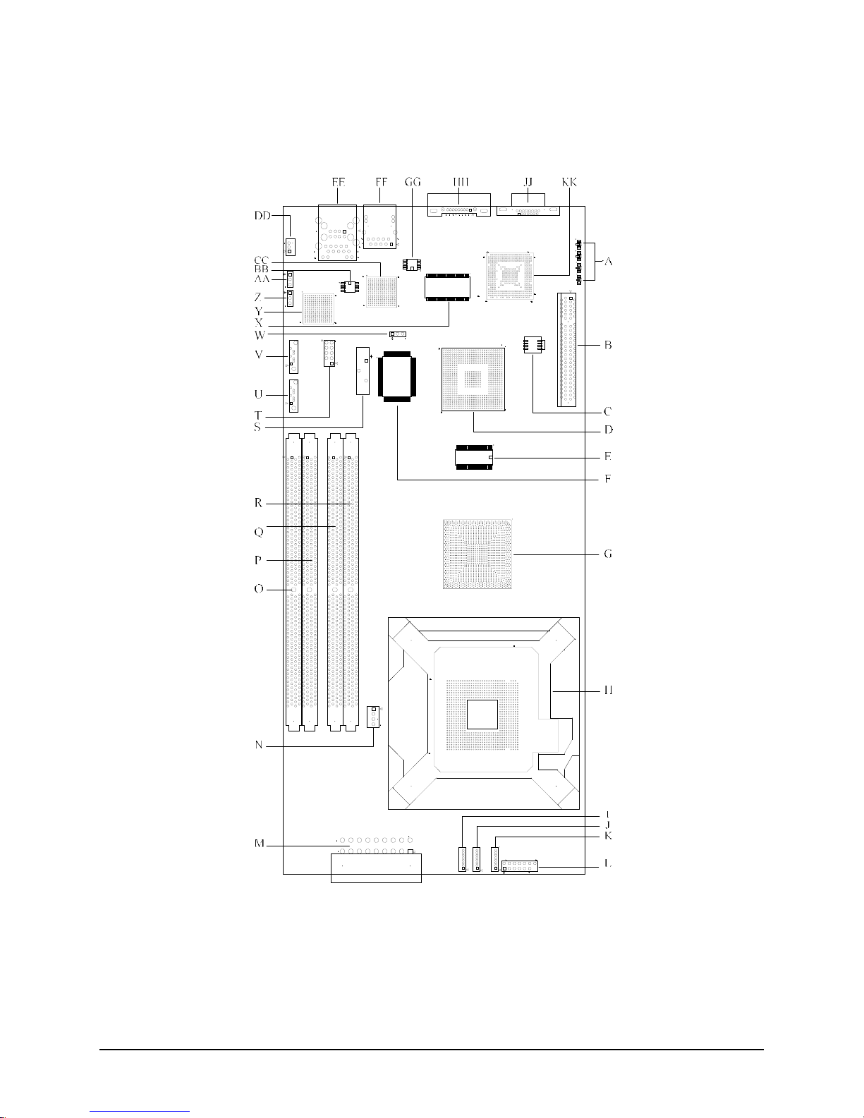
The following figure shows the board layout of the Intel® Server Board S3000PT. Each
connector and major component is identified by letter and is identified in Table 1.
Figure 1. Intel® Server Board S3000PT Layout
Page 13

Intel® Server Board S3000PT TPS Server Board Overview
Revision 1.3
5
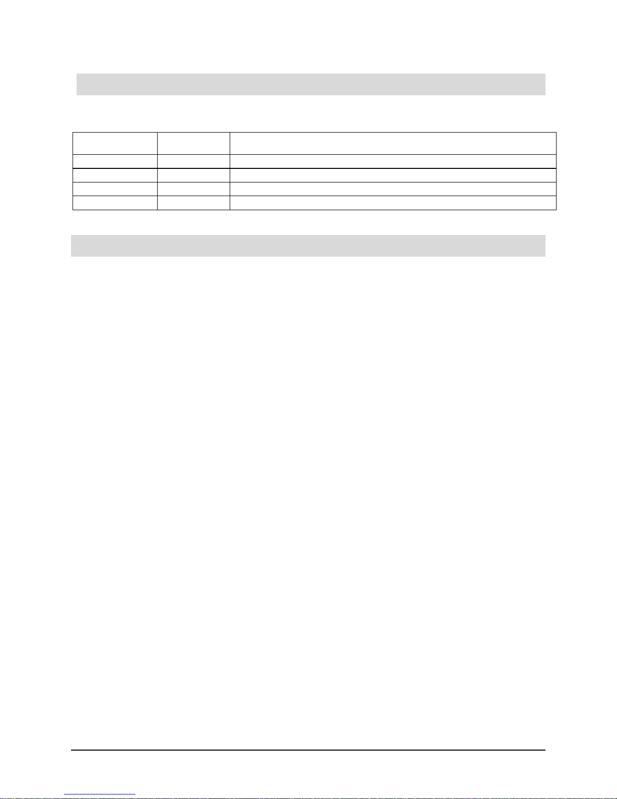
Table 1. Server Board Layout Reference
Ref
Description
Ref
Description
A
Post LEDs
S
Battery
B
PCI-E x8 riser slot
T
USB 3 and 4 header
C
BIOS Flash(SPI)
U
SATA port 2
D
Intel® 82802 ICH7R
V
SATA port 1
E
Clock generator
W
Serial B header
F
SMSC* SCH5027 or SMSC* SCH5017
Super I/O (SIO)
X
Video Memory
G
Intel®3000 Memory Controller Hub
(MCH)
Y
Intel® 82573E LAN Controller
H
775-Land (LGA) CPU Socket
Z
Intel® AMT firmware (NIC1) update jumper
I
System Fan 1 (8-pin)
AA
Clear CMOS jumper
J
System Fan 2 (8-pin)
BB
NIC1 SPI Flash
K
System Fan 3 (8-pin)
CC
Intel® 82573V LAN Controller
L
2 x 7 Front Panel header
DD
SMBus Connector
M
2 x 9 Power connector
EE
NIC1 RJ-45 and USB 1 and 2 connector
N
Auxiliary Fan (4-pin)
FF
NIC2 RJ-45 connector
O
Memory Slot DIMM 2B
GG
NIC2 SPI EEPROM
P
Memory Slot DIMM 1B
HH
Serial A connector
Q
Memory Slot DIMM 2A
JJ
VGA connector
R
Memory Slot DIMM 1A
KK
ATI* ES1000 video controller
Page 14
Functional Architecture Intel® Server Board S3000PT TPS
6 Revision 1.3
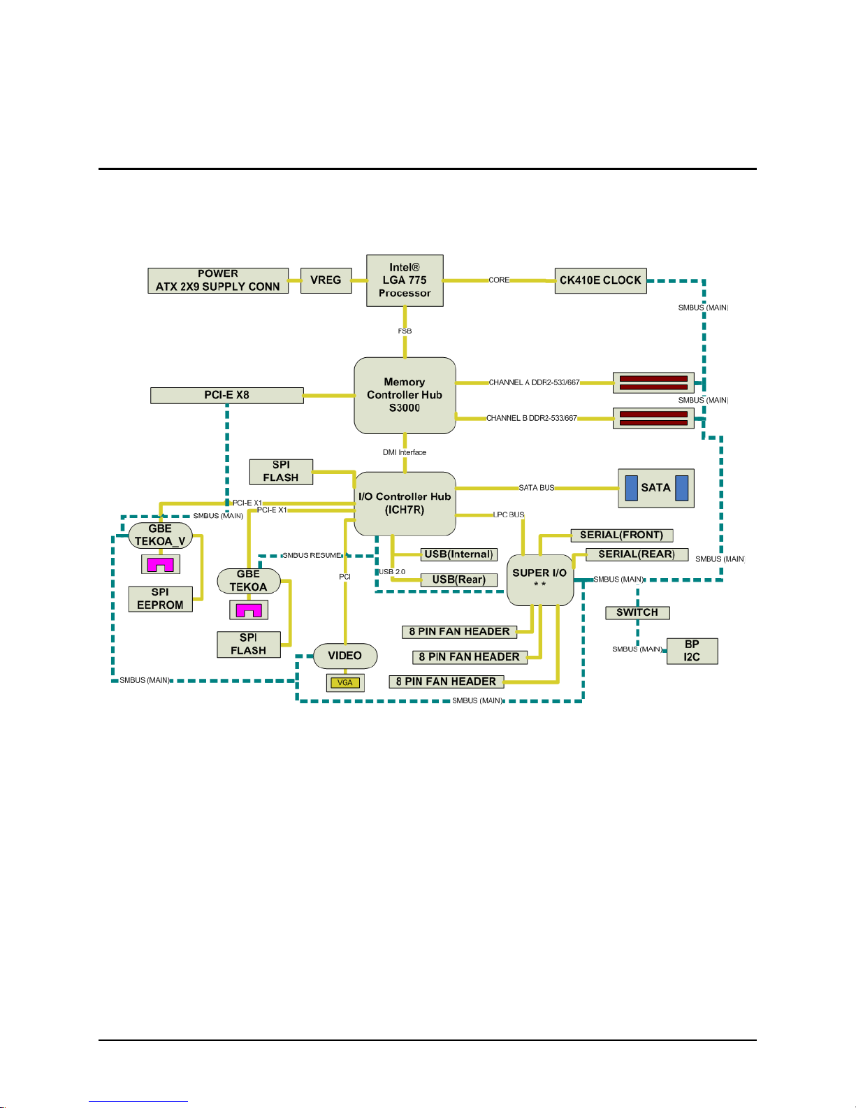
3. Functional Architecture
This section provides a high -level description of the functionality associated with the
architectural blocks that make up the Intel® Server Board S3000PT.
Figure 2. Intel® Server Board S3000PT Block Diagram
Page 15

Intel® Server Board S3000PT TPS Functional Architecture
Revision 1.3
7
3.1 Processor Sub-System
The Intel® Server Board S3000PT supports the following:
Intel® Xeon® processor 3000 sequence
Intel® Core™2 Extreme Edition
Intel® Core™2 Duo
Intel® Pentium® Processor Extreme Edition
Intel® Pentium® D Processor
Intel® Pentium® 4 Processor
Intel® Celeron® D Processor
The processors, built on 90nm and 65nm process technology in the 775 -land package, utilize
Flip-Chip Land Grid Array (FC-LGA4) package technology and plug into a 775-land LGA socket
(which is referred to as the Intel®LGA775 socket).
The processors in the 775-land package, like their predecessors in the 478 -pin package, are
based on the same Pentium® 4 micro -architecture. They maintain compatibility with 32 -bit
software written for the IA -32 instruction set, while supporting 64 -bit native mode operation
when coupled with supported 64 -bit operating systems and applications.
The Celeron® Processor is not available with dual core, Hyper -Threading Technology or Intel®
EM64T.
3.1.1 Processor Voltage Regulator Down (VRD)
The Intel® Server Board S3000PT has a VRD (Voltage Regulator Down) to
support one processor. It is compliant with the VRD 11 DC-DC Converter Design
Guide Line and provides a maximum of 125A, which is capable of supporting the
requirements for the following processors:
Intel® Xeon® processor 3000 sequence
Intel® Core™2 Extreme Edition
Intel® Core™2 Duo
Intel® Pentium® Processor Extreme Edition
Intel® Pentium® D Processor
Intel® Pentium® 4 Processor
Intel® Celeron® D Processor
The board hardware monitors the processor V TTEN (Output enable for VTT) pin before turning
on the VRD. If the VTTEN pin of the processors is not asserted, the Power ON Logic will not
turn on the VRD.
Page 16

Functional Architecture Intel® Server Board S3000PT TPS
8 Revision 1.3
3.1.2 Reset Configuration Logic
The BIOS determines the processor stepping, cache size, etc., through the CPUID instruction.
The processor information is read at every system power -on.
Note: The processor speed is the processor power -on reset default value. No manual
processor speed setting options exist either in the form of a BIOS setup option or jumpers.
3.1.3 Processor Support
The Intel® Server Board S3000PT supports one processor in the Intel®LGA775 package. The
support circuitry on the server board consists of the following:
One Intel® LGA775 processor socket supporting:
o Intel® Xeon® processor 3000 sequence
o Intel® Core™2 Extreme Edition processor
o Intel® Core™2 Duo processor
o Intel® Pentium® Processor Extreme Edition processor
o Intel® Pentium® D processor
o Intel® Pentium® 4 processor
o Intel® Celeron® D processor
Processor host bus AGTL+ support circuitry.
Table 2. Processor Support Matrix
Processor Name
Socket
Core
Frequency
Cache size
FSB Frequency
Intel® Xeon® 3000
Processor
Intel® LGA775
4MB L2
800/1066MHz
Intel® Xeon® 3000
Processor
Intel® LGA775
2MB L2
800/1066MHz
Intel® Core™2 Extreme
Edition
Intel® LGA775
2.93GHz
4MB L2
1066MHz
Intel® Core™2 Duo
Intel® LGA775
Intel® Pentium® 4
Processor Extreme Edition
Intel® LGA775
3.2GHz
2 x 1MB L2
800MHz
Intel® Pentium® 4
Processor Extreme Edition
Intel® LGA775
3.73GHz
2MB L2
1066MHz
Intel® Pentium® D
Intel® LGA775
3.2 – 4.0GHz
2 x 1MB L2
800MHz
Intel® Pentium® 4
Intel® LGA775
3.2 – 4.0GHz
1MB or 2MB L2
800MHz
Intel® Celeron® D
Intel®LGA775
2.26 – 3.2 GHz
256K L2
533MHz
Page 17

Intel® Server Board S3000PT TPS Functional Architecture
Revision 1.3
9
Note: For a complete list of all supported processors, please visit the Intel® Server Board
S3000PT support site located at the following URL:
http://support.intel.com/support/motherboards/server/S3000PT/
In addition to the circuitry described above, the processor subsystem contains the following:
Reset configuration logic
3.2 Intel®3000 Chipset
The Intel® Server Board S3000PT is designed around the Intel® 3000 chipset. The chipset
provides an integrated I/O bridg e and memory controller, and a flexible I/O subsystem core
(PCI Express*). The chipset consists of three primary components.
3.2.1 Memory Controller Hub (MCH)
3.2.1.1 Intel® 3000 Chipset MCH: Memory Control Hub
The MCH accepts access requests from the host (processor) b us and directs those accesses to
memory or to one of the PCI Express or PCI buses. The MCH monitors the host bus, examining
addresses for each request. Accesses may be directed to the following:
A memory request queue for subsequent forwarding to the memor y subsystem
An outbound request queue for subsequent forwarding to one of the PCI Express or PCI
buses
The MCH also accepts inbound requests from the Intel® ICH7R. The MCH is responsible for
generating the appropriate controls to control data transfer to a nd from memory.
The MCH is a 1202-ball FC-BGA device and uses the proven components of the following
previous generations:
Pentium® Processor Extreme Edition , Pentium® D Processor , Pentium® 4 Processor,
Celeron® D Processor bus interface unit
Hub interface unit
PCI Express interface unit
DDR2 memory interface unit
The MCH incorporates an integrated PCI Express* interface. The PCI Express* interface allows
the MCH to directly interface with the PCI Express* devices. The MCH also increases the main
memory interface bandwidth and maximum memory configuration with a 72-bit wide memory
interface.
The MCH integrates the following main functions:
An integrated high performance main memory subsystem
A PCI Express* bus which provides an interface to the PCI-Express devices( Fully
compliant to the PCI Express* Base Specification, Rev 1.0a )
A DMI which provides an interface to the Intel® ICH7R
Page 18
Functional Architecture Intel® Server Board S3000PT TPS
10 Revision 1.3
Other features provided by the MCH include the following:
Full support of ECC on the DDR2 memory bus
Twelve deep in-order queue, two deep defer queue
Full support of un-buffered DDR2 ECC DIMMs
Support for 256-MB, 512-MB, 1-GB and 2-GB DDR2 memory modules
3.2.1.2 Segment D PCI-Express x8
In this board, the MCH PCIe Lanes 0~7 are connected to an x8 PCI -E riser connector directly
through the MCH. It can support x1, x4, and x8 PCI-E add-in cards through a riser card.
Table 3. Segment E Connections
Lane
Device
Lane 0~7
Slot 1 (PCI Express* x8)
3.2.1.3 MCH Memory Sub-System Overview
The MCH supports a 72-bit wide memory sub-system that can support a maximum of 8 GB of
DDR2 memory using 2GB DIMMs. This configuration needs external registers for buffering the
memory address and control signals. The four chip selects are registered inside the MCH and
need no external registers fo r chip selects.
The memory interface runs at 533/667MT/s. The memory interface supports a 72 -bit wide
memory array. It uses seventeen address lines (BA [2:0] and MA [13:0]) and supports 256-MB,
512-MB, 1-GB, and 2-GB DRAM densities. The DDR DIMM interface supports single-bit error
correction, and multiple bit error detection .
3.2.1.3.1 DDR2 Configurations
The DDR2 interface supports up to 8 GB of main memory and supports single - and doubledensity DIMMs. The DDR2 can be any industry-standard DDR2. The following table shows the
DDR2 DIMM technology supported.
Table 4. Supported DDR2 Modules
DDR2-533/667 Un-buffered
SDRAM Module Matrix
DIMM
Capacity
DIMM
Organization
SDRAM
Density
SDRAM
Organization
# SDRAM
Devices/rows/Banks
# Address bits
rows/Banks/column
256MB
32M x 72
256Mbit
32M x 8
9 /1 / 4
13 / 2 / 10
512MB
64M x 72
256Mbit
32M x 8
18 / 2 / 4
13 / 2 / 10
512MB
64M x 72
512Mbit
64M x 8
9 / 1 / 4
14 / 2 / 10
1GB
128M x 72
512Mbit
64M x 8
18 / 2 / 4
14 / 2 / 10
1GB
128M x 72
1Gbit
128M x 8
9 / 1 / 8
14 / 4 / 10
2GB
256M x 72
1Gbit
128M x 8
18 / 2 / 8
14 / 8 / 10
Page 19

Intel® Server Board S3000PT TPS Functional Architecture
Revision 1.3
11
3.2.2 I/O Controller Hub
3.2.2.1 Intel® ICH7R: I/O Controller Hub 7R
The Intel® ICH7R controller has several components. It provides the interface for a
32-bit/33-MHz PCI bus. The Intel® ICH7R controller can be both a master and a target on that
PCI bus and includes a USB 2.0 controller and an IDE controller. The Intel® ICH7R controller is
also responsible for much of the power management functions, with ACPI control registers built
in. It also provides a number of GPIO pins and has the LPC bus to support low -speed Legacy
I/O.
The MCH and Intel® ICH7R chips provide the pathway between the processor and the I/O
systems. The MCH is responsible for accepting access requests from the host (pro cessor) bus,
and directing all I/O accesses to one of the PCI buses or Legacy I/O locations. If the cycle is
directed to one of the PCI Express* segments, the MCH communicates with the PCI Express*
devices (add-in card, on board devices) through the PCI Express* interface. If the cycle is
directed to the Intel® ICH7R controller, the cycle is output on the MCH’s DMI bus. All I/O for the
board, including PCI and PC -compatible I/O, is directed through the MCH and then through the
Intel® ICH7R provided PCI buses.
The Intel® ICH7R controller is a multi-function device, housed in a 652-pin mBGA device. It
provides the following:
A DMI bus
A PCI 32-bit/33-MHz interface
An IDE interface
An integrated serial ATA Host controller
A USB controller
A PCI Express* x4 inte rface
Two PCI Express* x1 interface
A power management controller
Each function within the Intel® ICH7R controller has its own set of configuration registers. Once
configured, each appears to the system as a distinct hardware controller sharing the same PC I
bus interface.
The primary role of the Intel® ICH7R controller is providing the gateway to all PC -compatible
I/O devices and features. The board uses the following Intel® ICH7R features:
PCI 32-bit/33MHz interface to dedicated ATI* ES1000 video subsystem
LPC bus interface
x1 PCI Express* interface for Intel® 82573E Gigabit Ethernet Controller
x1 PCI Express* interface for Intel® 82573 V Gigabit Ethernet Controller
DMI (Direct Media Interface)
Integrated dual-port Serial ATA Host controller
Universal Serial Bus (USB) 2.0 interface
PC-compatible timer/counter and DMA controllers
APIC and 82C59 interrupt controller
Page 20

Functional Architecture Intel® Server Board S3000PT TPS
12 Revision 1.3
Power management
System RTC
Supports the SMBus 2.0 Specification
General-purpose I/O (GPIO)
The following are the descriptions of how each supporte d feature is used for the Intel® ICH7R
controller on the board.
3.2.2.1.1 SATA Controller
The Intel® ICH7R controller has an integrated SATA host controller that supports independent
DMA operation on four ports and supports data transfer rates of up to 3.0 Gb/s (300 MB/s).
3.2.2.2 Compatibility Modules (DMA Controller, Timer/Counters, Interrupt
Controller)
The DMA controller incorporates the logic of two Intel® 82C37 DMA controllers, with seven
independently programmable channels. Channels 0 –3 are hardwired to 8-bit, count-by-byte
transfers, and channels 5 –7 are hardwired to 16-bit, count-by-word transfers. Any two of the
seven DMA channels can be programmed to support fast Type -F transfers.
The timer/counter block contains three counters that are equivalent in function to t hose found in
one Intel® 82C54 programmable interval timer. These three counters are combined to provide
the system timer function, and speaker tone. The 14.31818 -MHz oscillator input provides the
clock source for these three counters.
The Intel® ICH7R controller provides an ISA-Compatible Programmable Interrupt Controller
(PIC) that incorporates the functionality of two, 82C59 interrupt controllers. The two interrupt
controllers are cascaded so that 14 external and two internal interrupts are possible. In addition,
the Intel® ICH7R controller supports a serial interrupt scheme.
All of the registers in these modules can be read and restored. This is required to save and
restore the system state after power has been removed and restored to the platform.
3.2.2.2.1 Advanced Programmable Interrupt Controller (APIC)
In addition to the standard ISA compatible Programmable Interrupt controller (PIC) described in
the previous section, the Intel® ICH7R incorporates the Advanced Programmable Interrupt
Controller (APIC).
3.2.2.2.2 Universal Serial Bus (USB) Controller
The Intel® ICH7R controller contains one EHCI* USB 2.0 controller and four USB ports. The
USB controller moves data between main memory and up to four USB connectors. All ports
function identically and with the same bandwidth . The Intel® Server Board S3000PT
implements four ports on the board.
Two external USB ports are provided on the back of the server board. The Universal Serial Bus
Specification, Revision 1.1, defines the external connectors.
Page 21

Intel® Server Board S3000PT TPS Functional Architecture
Revision 1.3
13
The third/fourth USB port is optional and can be accessed by cabling from an internal 9 -pin
connector located on the server board to an external USB port located either in front of or on
the rear of a given chassis.
3.2.2.2.3 Enhanced Power Management
The Intel® ICH7R controller’s power management functions include enhanced clock control and
various low-power (suspend) states (e.g., Suspend -to-RAM and Suspend-to-Disk). A hardwarebased thermal management circuit permits a software-independent entrance to low -power
states. The Intel® ICH7R controller contains full support for the Advanced Configuration and
Power Interface (ACPI) Specification, Revision 3.0. The server board supports sleep states S1,
S4, and S5.
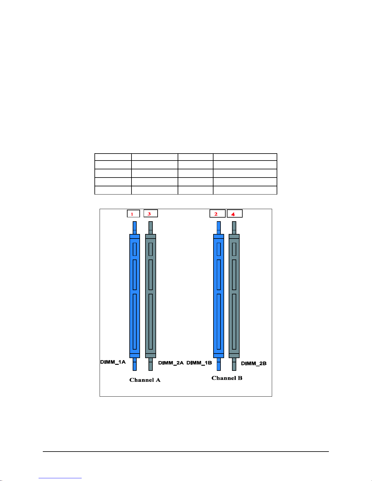
3.3 Memory Sub-System
The memory interface between the MCH and the DIMMs is a 72-bit (ECC) wide interface.
There are two banks of DIMMs, labeled 1 and 2. Bank 1 contains DIMM socket locations
DIMM_1A and DIMM_1B. Bank 2 contains DIMM socket locations DIMM _2A and DIMM_2B.
The sockets associated with each bank , or “channel,” are located next to each other, and the
DIMM socket identifiers are marked on the base board silkscreen, near the DIMM socket. When
only two DIMM modules are being used, the population order must be DIMM_1A, DIMM_1B to
ensure dual-channel operating mode.
In order to operate in dual-channel dynamic paging mode, the following conditions must be met:
Two identical DIMMs are installed, one each in DIMM_1A and DIMM_1B
Four identical DIMMs are installed (one in each socket location)
Note: Installing only three DIMMs is not supported . Do not use DIMMs that are not “matched”
(same type and speed). Use of identical memory parts is always the preferred method.
See Figure 3 for reference.
The system design is free to populate or not to populate any rank on either channel, including
either degenerate single channel case.
Page 22
Functional Architecture Intel® Server Board S3000PT TPS
14 Revision 1.3
DIMM and memory configurations must adhere to the following:
DDR2 533/667, un-buffered, DDR2 DIMM modules
DIMM organization: x72 ECC
Pin count: 240
DIMM capacity:512 MB, 1 GB and 2 GB DIMMs
Serial PD: JEDEC Rev 2.0
Voltage options: 1.8 V
Interface: SSTL2
Table 5. Memory Bank Labels and DIMM Population Order
Location
DIMM Label
Channel
Population Order
J2D1
(DIMM_1A)
A
1
J1D2
(DIMM_2A)
A
3
J1D3
(DIMM_1B)
B
2
J1D1
(DIMM_2B)
B
4
Figure 3. Memory Bank Label Definition
Page 23

Intel® Server Board S3000PT TPS Functional Architecture
Revision 1.3
15
Table 6. Characteristics of Dual/Single Channel Configuration with or without Dynamic Mode
Throughput Level
Configuration
Characteristics
Highest
Dual channel with dynamic paging mode
All DIMMs matched
Dual channel without dynamic paging mode
DIMMs matched from Channel A to Channel B
DIMMs not matched within channels
Single channel with dynamic paging mode
Single DIMM or DIMMs matched within a
channel
Lowest
Single channel without dynamic paging
mode
DIMMs not matched
3.3.1 Memory DIMM Support
The board supports un-buffered (not registered) DDR2 533/667 ECC DIMMs operating at
533/667MT/s. Only DIMMs tested and qualified by Intel o r a designated memory test vendor are
supported on this board. A list of qualified DIMMs is available at
http://support.intel.com/support/motherboards/server/ .
Note: All DIMMs are supported by design, but only fully qualified DIMMs will be supported on
the board.
The minimum supported DIMM size is 256 MB. Therefore, the minimum main memory
configuration is 1 x 256 MB or 256 MB. The largest size DIMM supported is 2 GB and as such,
the maximum main memory configuration is 8 GB implemented by 4 x 2-GB DIMMs.
Only un-buffered DDR2 533/667 compliant, ECC x8 or x16 memory DIMMs are
supported.
ECC single-bit errors (SBE) will be corrected; multiple -bit error (MBE) will only be
detected.
Intel® Server Board S3000PT supports Intel® x4 Single Device Data Correction with x4
DIMMs.
The maximum memory capacity is 8 GB via four 2 -GB DIMM modules.
The minimum memory capacity is 256 MB via a single 256-MB DIMM module.
3.4 I/O Sub-System
3.4.1 PCI Subsystem
There are three independent PCI bus segments directed from the Intel® ICH7R controller on
the Intel® Server Board S3000PT. PCI Segment A is a legacy PCI bus while PCI Segments B
and C are PCI Express*.
Page 24

Functional Architecture Intel® Server Board S3000PT TPS
16 Revision 1.3
3.4.1.1.1 Device IDs (IDSEL)
Each device under the PCI hub bridge has its IDSEL signal connected to one bit of AD (31:16),
which acts as a chip select on the PCI bus segment in configuration cycles. This determines a
unique PCI device ID value for use in configuration cycles. The following table shows the bit to
which each IDSEL signal is attached for Segment A devices and the corresponding device
description.
Table 7. Segment A Configuration IDs
IDSEL Value
Device
20
ATI* ES1000 video controller
3.4.1.1.2 Segment A Arbitration
PCI Segment A supports two PCI devices: the Intel® ICH7 R and one PCI bus master (NIC). All
PCI masters must arbitrate for PCI access, using resources supplied by the Intel® ICH7 R. The
host bridge PCI interface (ICH7 R) arbitration lines REQx* and GNTx* are a special case in that
they are internal to the host bridge. The following table defines the arbitration connections.
Table 8. Segment A Arbitration Connections
Server Board Signals
Device
PCI REQ_N4/GNT_N4
ATI* ES1000 video controller
3.4.2 Interrupt Routing
The board interrupt architecture accommodates both PC -compatible PIC mode and APIC mode
interrupts through use of the integrated I/O APICs in the Intel® ICH7R controller.
3.4.2.1 Legacy Interrupt Routing
For PC-compatible mode, the Intel® ICH7R controller provides two 82C59-compatible interrupt
controllers. The two controllers are cascaded with interrupt levels 8 -15 entering on level 2 of the
primary interrupt controller (standard PC configuration). A single interrupt signal is presented to
the processors, to which only one processor will respond for servicing. The Intel® ICH7R
contains configuration registers that define which interrupt source logically maps to I/O APIC
INTx pins.
The Intel® ICH7R controller handles both PCI and IRQ interrupts. The Intel® ICH7R translates
these to the APIC bus. The numbers in the following table indicate the Intel® ICH7R PCI
interrupt input pin to which the associated device interrupt (INTA, INTB, INTC, INTD, INT E,
INTF, INTG, INTH for PCI bus and PXIRQ0, PXIRQ1, PXIRQ2, PXIRQ3 for PCI-X bus) is
connected. The Intel® ICH7R I/O APIC exists on the I/O APIC bus with the processors.
Page 25

Intel® Server Board S3000PT TPS Functional Architecture
Revision 1.3
17
Table 9. PCI Interrupt Routing/Sharing
Interrupt
INT A
INT B
INT C
INT D
ATIES 1000
PIRQC
3.4.2.2 APIC Interrupt Routing
For APIC mode, the ser ver board interrupt architecture incorporates three Intel® I/O APIC
devices to manage and broadcast interrupts to local APICs in each processor. The Intel® I/O
APICs monitor each interrupt on each PCI device, including PCI slots in addition to the ISA
compatibility interrupts IRQ (0 -15).
When an interrupt occurs, a message corresponding to the interrupt is sent across a three -wire
serial interface to the local APICs. The APIC bus minimizes interrupt latency time for
compatibility interrupt sources. The I/O APICs can also supply greater than 16 interrupt levels to
the processor(s). This APIC bus consists of an APIC clock and two bi -directional data lines.
3.4.2.3 Legacy Interrupt Sources
The following table recommends the logical interrupt mapping of interrupt sourc es on the board.
The actual interrupt map is defined using configuration registers in the Intel® ICH7R controller.
Table 10. Interrupt Definitions
ISA Interrupt
Description
INTR
Processor interrupt
NMI
NMI to processor
IRQ0
System timer
IRQ1
Keyboard interrupt
IRQ2
Slave PIC
IRQ3
Serial port 1 interrupt from Super I/O* device, user-configurable
IRQ4
Serial port 1 interrupt from Super I/O* device, user-configurable
IRQ5
IRQ6
Floppy disk
IRQ7
Generic
IRQ8_L
Active low RTC interrupt
IRQ9
SCI*
IRQ10
Generic
IRQ11
Generic
IRQ12
Mouse interrupt
IRQ13
Floating point processor
IRQ14
Compatibility IDE interrupt from prim ary channel IDE devices 0 and 1
IRQ15
Secondary IDE cable
SMI*
System Management Interrupt. General -purpose indicator sourced by the Intel® ICH7R
Controller to the processors.
Page 26

Functional Architecture Intel® Server Board S3000PT TPS
18 Revision 1.3
3.4.2.4 Serialized IRQ Support
The Intel® Server Board S3000PT supports a serialized interrupt delivery mechanism.
Serialized Interrupt Requests (SERIRQ) consists of a start frame, a minimum o f 17 IRQ / data
channels, and a stop frame. Any slave device in the quiet mode may initiate the start frame.
While in the continuous mode, the start frame is initiated by the host controller.
3.5 PCI Error Handling
The PCI bus defines two error pins, PERR# and SERR#, for reporting PCI parity errors and
system errors, respectively. In the case of PERR#, the PCI bus master has the option to retry
the offending transaction, or to report it using SERR#. All other PCI -related errors are reported
by SERR#. SERR# is routed to the NMI if enabled by the BIOS.
Page 27
Intel® Server Board S3000PT TPS Functional Architecture
Revision 1.3
19
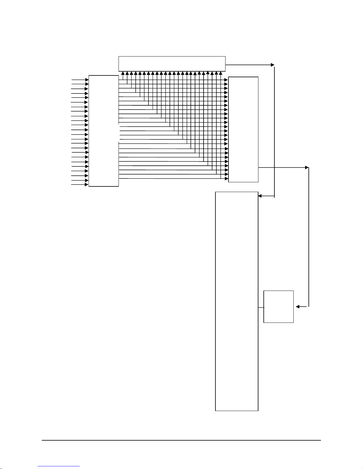
Figure 4. Interrupt Routing Diagram
IRQ0
IRQ1
IRQ2
IRQ3
IRQ4
IRQ5
IRQ6
IRQ7
IRQ8
IRQ9
IRQ10
IRQ11
IRQ12
IRQ13
IRQ14
IRQ15
IRQ16
IRQ17
IRQ18
IRQ19
IRQ20
IRQ21
IRQ22
IRQ23
Intel® ICH7R
Controller IOAPIC 0
Intel®
ICH7R
Controller
MCH
Intel®
ICH7R
Controller
8259PIC
CPU
INTR
DMI INTERFACE
Page 28
Functional Architecture Intel® Server Board S3000PT TPS
20 Revision 1.3
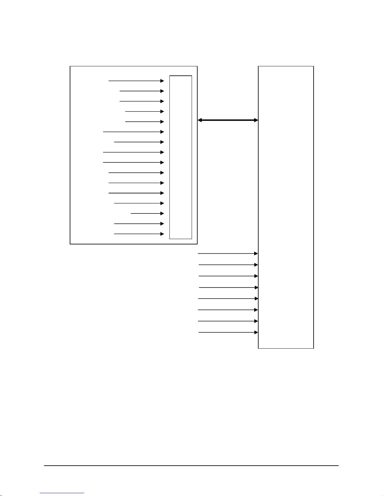
Figure 5. Intel® ICH7R Controller Interrupt Routing Diagram
PIRQB#
PIRQD#
PIRQC#
PIRQE#
PIRQF#
PIRQG#
PIRQH#
PIRQA#
Super I/O
Timer
Keyboard
Serial Port2/ISA
Serial Port1/ISA
ISA
Floppy/ISA
ISA
RTC
SCI/ISA
ISA
ISA
Mouse/ISA
Coprocessor Error
P_IDE/ISA
Not Used
Cascade
Serialized IRQ Interface
SERIRQ
N/A
N/A
N/A
SERIRQ
Intel® ICH7R
Controller Interrupt
Routing
N/A
N/A
ATI ES1000
N/A
N/A
Page 29

Intel® Server Board S3000PT TPS Functional Architecture
Revision 1.3
21
3.5.1 Video Support
The Intel® Server Board S300 0PT includes an integrated standalone ATI* ES1000 graphics
engine that supports standard VGA drivers with analog display capabilities. The graphics
subsystem has 16 MB of dedicated memory to support the onboard video controller. The
baseboard provides a standard 15 -pin VGA connector at the rear of the system, in the I/O
opening area.
3.5.1.1 Video Modes
Table 11. Video Modes
2D Video Mode Support
2D Mode
Refresh Rate (Hz)
8 bpp
16 bpp
24 bpp
32 bpp
640x480
60, 72, 75, 90, 100
Supported
Supported
Supported
Supported
800x600
60, 70, 75, 90, 100
Supported
Supported
Supported
Supported
1024x768
60, 72, 75, 90, 100
Supported
Supported
Supported
Supported
1280x1024
43, 60
Supported
Supported
Supported
Supported
1280x1024
70, 72
Supported
–
Supported
Supported
3D Video Mode Support with Z Buffer Enabled
3D Mode
Refresh Rate (Hz)
8 bpp
16 bpp
24 bpp
32 bpp
640x480
60,72,75,90,100
Supported
Supported
Supported
Supported
800x600
60,70,75,90,100
Supported
Supported
Supported
Supported
1024x768
60,72,75,90,100
Supported
Supported
Supported
Supported
1280x1024
43,60,70,72
Supported
Supported––
3D Video Mode Support with Z Buffer Disabled
3D Mode
Refresh Rate (Hz)
8 bpp
16 bpp
24 bpp
32 bpp
640x480
60,72,75,90,100
Supported
Supported
Supported
Supported
800x600
60,70,75,90,100
Supported
Supported
Supported
Supported
1024x768
60,72,75,90,100
Supported
Supported
Supported
Supported
1280x1024
43,60,70,72
Supported
Supported
Supported
–
3.5.2 Network Interface Controller (NIC)
The Intel® Server Board S3000PT supports two 10/100/1000 Base-T network interfaces.
NIC1 is an Intel® 82573E Gigabit Ethernet Controller resourced with a x1 PCI Express*
interface from the Intel® ICH7R (PCI Segment C).
NIC2 is an Intel® 82573V Gigabit Ethernet Controller resourced with a x1 PCI Express*
interface from the Intel® ICH7R (PCI Segment B).
Both the Intel® 82573E and Intel® 82573V Gigabit Ethernet Controllers are single,
compact components with an integrated gigabit Ethernet Media Access Control (MAC)
and physical layer (PHY) function. The Intel® 82573E and Intel® 82573V Gigabit
Ethernet Controller allow for a gigabit Ethernet implementation in a very small area that
is footprint compatible with current generation 10/100 Mbps Fast Ethernet designs.
Intel® 82573E/V integrates fourth and fifth generation (respectively) giga bit MAC design
with fully integrated physical layer circuitry to provide a standard IEEE 802.3 Ethernet
Page 30

Functional Architecture Intel® Server Board S3000PT TPS
22 Revision 1.3
interface for 1000BASE -T, 100BASE-TX, and 10BASE-T applications (802.3, 802.3u,
and 802.3ab). The controller is capable of transmitting and receiving da ta at rates of
1000 Mbps, 100 Mbps, or 10 Mbps.
3.5.2.1 NIC Connector and Status LEDs
The NICs drive two LEDs located on each network interface connector.
Table 12. Intel® 82573E Interface Connector (NIC1)
LED
Color
LED State
Condition
Off
LAN link is not established.
On
LAN link is established.
Left
Green
Blinking
LAN activity is occurring.
N/A
Off
10 Mbit/sec data rate is selected.
Green
On
100 Mbit/sec data rate is selected.
Right
Yellow
On
1000 Mbit/sec data rate is selected.
Table 13. Intel® 82573V Interface Connector (NIC2)
LED
Color
LED State
Condition
Off
LAN link is not established.
On
LAN link is established.
Right
Green
Blinking
LAN activity is occurring.
N/A
Off
10 Mbit/sec data ra te is selected.
Green
On
100 Mbit/sec data rate is selected.
Left
Yellow
On
1000 Mbit/sec data rate is selected.
3.5.3 Super I/O Chip
The SMsC* SCH5027 or SCH5017 SIO devices contain all of the necessary circuitry to control
serial/parallel ports, floppy disk, PS/2-compatible keyboard, mouse and hardware monitor
controller. The baseboard implements the following features:
GPIOs
One full functional serial port
One Tx/Rx only serial port for debug only
Local hardware monitoring
Wake up control
System health support
3.5.3.1 Serial Ports
The board provides a serial port implemented as an external 9 -pin serial port; an internal 3-pin
Tx/Rx only serial port is also provided. The following sections provide details on the use of the
serial port.
Page 31

Intel® Server Board S3000PT TPS Functional Architecture
Revision 1.3
23
3.5.3.1.1 Serial Port A
Serial A is a standard DB9 interface located at the rear I/O panel of the server board, above the
video connector. Serial A is designated by a Serial_ A on the silkscreen. The reference
designator is J3A1.
Serial B is a 3-pin header interface located near the SIO. Serial B is designated by a Serial_ B
on the silkscreen. The reference designator is J2B1.
Table 14. Serial A Header Pin-out
Pin
Signal Name
Serial Port A Header Pin -out
1
DCD
2
RXD
3
TXD
4
DTR
5
GND
6
DSR
7
RTS
8
CTS
9
RI
Table 15. Serial B Header Pin-out
Pin
Signal Name
Serial Port B Header Pin-out
1
RXD
2
GND
3
TXD
GND
3-pin Serial B header
Tx
Rx
1
2
3
3.5.3.2 Keyboard and Mouse Support
USB ports can be used to support keyboard and mouse. No PS/2 port is available.
3.5.3.3 Wake-up Control
The Super I/O contains functionality that allows various events to control the power -on and
power-off the system.
3.5.4 BIOS Flash
The board incorporates a SPI flash memory which can work with 16 megabit SPI serial flash
devices that provide 1024K x 8 or 512K x 8 of BIOS and non-volatile storage space. The flash
device is connected through th e SPI bus from the Intel® ICH7R controller.
Page 32
Functional Architecture Intel® Server Board S3000PT TPS
24 Revision 1.3
3.5.5 System Health Support
SMBus 2.0 is the interface used to connect the system health sensors of the Super I/O SMsC*
SCH5027 or SCH5017 chip. The following is supported:
Three PWM-based fan controls and six fan speed tachometers
Software or local temperature feedback control
Voltage measurement and monitor
3.6 Replacing the Back-Up Battery
The lithium battery on the server board powers the RTC for up to ten years in the absence of
power. When the battery starts to weaken, it loses voltage, and the server settings stored in
CMOS RAM in the RTC (for example, the date and time) may be wrong. C ontact your customer
service representative or dealer for a list of approved devices.
WARNING
Danger of explosion if battery is incorrectly replaced. Replace only with the same or equivalent
type recommended by the equipment manufacturer. Discard used ba tteries according to
manufacturer’s instructions.
ADVARSEL!
Lithiumbatteri - Eksplosionsfare ved fejlagtig håndtering. Udskiftning må kun ske med batteri af
samme fabrikat og type. Levér det brugte batteri tilbage til leverandøren.
ADVARSEL
Lithiumbatteri - Eksplosjonsfare. Ved utskifting benyttes kun batteri som anbefalt av
apparatfabrikanten. Brukt batteri returneres apparatleverandøren.
VARNING
Explosionsfara vid felaktigt batteribyte. Använd samma batterityp eller en ekvivalent typ som
rekommenderas av apparattillverkaren. Kassera använt batteri enligt fabrikantens instruktion.
VAROITUS
Paristo voi räjähtää, jos se on virheellisesti asennettu. Vaihda paristo ainoastaan
laitevalmistajan suosittelemaan tyyppiin. Hävitä käytetty paristo valmistajan ohjeiden
mukaisesti.
Page 33

Intel® Server Board S3000PT System BIOS
Revision 1.3
25
4. System BIOS
4.1 BIOS Identification String
The BIOS Identification string is used to uniquely identify the revision of the BIOS being used
on the server. The string is formatted as follows:
BoardFamilyID.OEMID.MajorRev.MinorRev.BuildID.B uildDateTime
Where:
BoardFamilyID = String name for this board family.
OEMID = Three-character OEM ID. “86B” is used for Intel EPSD.
MajorRev = Two decimal digits
MinorRev = Two decimal digits
BuildID = Four decimal digits
BuildDateTime = Build date and t ime in MMDDYYYYHHMM format:
- MM = Two-digit month
- DD = Two-digit day of month
- YYYY = Four-digit year
- HH = Two-digit hour using 24 hour clock
- MM = Two-digit minute
4.2 Logo / Diagnostic Window
The Logo / Diagnostic window may be i n one of two forms. In Quiet B oot mode, a logo splash
screen is displayed. In Verbose mode, a system summary and diagnostic screen is displayed.
The default is to display the logo in Quiet Boot mode. If no logo is present in the flash ROM, or
if Quiet Boot mode is disabled in the system configuration, the summary and diagnostic screen
is displayed.
The diagnostic screen consists of the following information :
BIOS ID.
Total memory detected (t otal size of all installed DIMMs)
Processor information (Intel branded string, speed, and number of physical processors
identified)
Types of keyboards detected , if plugged in
Types of mouse devices detected , if plugged in
Page 34

System BIOS Intel® Server Board S3000PT TPS
26 Revision 1.3
4.3 BIOS Setup Utility
The BIOS Setup utility is a text -based utility that allows the user to configure the system and
view current settings and environment information for the platform devices. The Setup utility
controls the platform's built -in devices.
The BIOS Setup interface consists of a number of pages or screens. Each page contains
information or links to other pages. The first page in Setup displays a list of general categories
as links. These links lead to pages containing a specific category’s configuration.
The following sections describe the look and behavior for the platform Setup.
4.3.1 Operation
BIOS Setup has the following f eatures:
Localization. The Intel Server Board BIOS will only be available in English.
BIOS Setup is functional via console redirection over various terminal emulation
standards. This may limit some functionality for compatibility , e.g., usage of colors or
some keys or key sequences or support of pointing devices.
4.3.1.1 Setup Page Layout
The setup page layout is sectioned into functional areas. Each occupies a specific area of the
screen and has dedicated functionality. The following table lists and describes eac h functional
area.
Table 16. BIOS Setup Page Layout
Functional Area
Description
Title Bar
The title bar is located at the top of the screen and displays the title of the form
(page) the user is currently viewing. It may also displa y navigational information.
Setup Item List
The Setup Item List is a set of controllable and informational items. Each item in the
list occupies the left and center columns in the middle of the screen. The left
column, the "Setup Item", is the subject of the item. The middle column, the
"Option", contains an informational value or choices of the subject.
A Setup Item may also be a hyperlink that is used to navigate formsets (pages).
When it is a hyperlink, a Setup Item only occupies the “Setup Item” colum n.
Item Specific Help Area
The Item Specific Help area is located on the right side of the screen and contains
help text for the highlighted Setup Item. Help information includes the meaning and
usage of the item, allowable values, effects of the options, etc.
Keyboard Command Bar
The Keyboard Command Bar is located at the bottom right of the screen and
continuously displays help for keyboard special keys and navigation keys. The
keyboard command bar is context -sensitive—it displays keys relevant to curre nt
page and mode.
Status Bar
The Status Bar occupies the bottom line of the screen. This line would display the
BIOS ID.
Page 35

Intel® Server Board S3000PT System BIOS
Revision 1.3
27
4.3.1.2 Entering BIOS Setup
BIOS Setup is started by pressing <F2> during boot time when the OEM or Intel logo is
displayed.
When Quiet Boot is disabled, there will be a message “press <F2> to enter setup” displayed on
the diagnostics screen.
4.3.1.3 Keyboard Commands
The bottom right portion of the Setup screen provides a list of commands that are used to
navigate through the Setup utility. These c ommands are displayed at all times.
Each Setup menu page contains a number of features. Except those used for informative
purposes, each feature is associated with a value field. This field contains user -selectable
parameters. Depending on the security opt ion chosen and in effect by the password, a menu
feature’s value may or may not be changeable. If a value is non -changeable, the feature’s value
field is inaccessible. It displays as “grayed out.”
The Keyboard Command Bar supports the following:
Table 17. BIOS Setup: Keyboard Command Bar
Key
Option
Description
<Enter>
Execute
Command
The <Enter> key is used to activate sub -menus when the selected feature is a
sub-menu, or to display a pick list if a selected option has a value field , or to select
a sub-field for multi-valued features like time and date. If a pick list is displayed,
the <Enter> key will select the currently highlighted item, undo the pick list, and
return the focus to the parent menu.
<Esc>
Exit
The <Esc> key provide s a mechanism for backing out of any field. This key will
undo the pressing of the Enter key. When the <Esc> key is pressed while editing
any field or selecting features of a menu, the parent menu is re -entered.
When the <Esc> key is pressed in any sub -menu, the parent menu is re -entered.
When the <Esc> key is pressed in any major menu, the exit confirmation window
is displayed and the user is asked whether changes can be discarded. If “No” is
selected and the <Enter> key is pressed, or if the <Esc> key is pressed, the user
is returned to where he/she was before <Esc> was pressed, without affecting any
existing any settings. If “Yes” is selected and the <Enter> key is pressed, setup is
exited and the BIOS returns to the main System Options Menu screen.
Select Item
The up arrow is used to select the previous value in a pick list, or the previous
option in a menu item's option list. The selected item must then be activated by
pressing the <Enter> key.
Select Item
The down arrow is used to select the next value in a menu item’s option list, or a
value field’s pick list. The selected item must then be activated by pressing the
<Enter> key.
Select Menu
The left and right arrow keys are used to move between the major menu pages.
The keys have no affect if a sub-menu or pick list is displayed.
<Tab>
Select Field
The <Tab> key is used to move between fields. For example, <Tab> can be used
to move from hours to minutes in the time item in the main menu.
-
Change Value
The minus key on the keypad is used to c hange the value of the current item to the
previous value. This key scrolls through the values in the associated pick list
without displaying the full list.
Page 36

System BIOS Intel® Server Board S3000PT TPS
28 Revision 1.3
Key
Option
Description
+
Change Value
The plus key on the keypad is used to change the value of the current menu item
to the next value. This key scrolls through the values in the associated pick list
without displaying the full list. On 106 -key Japanese keyboards, the plus key has a
different scan code than the plus key on the other keyboard, but will have the
same effect.
<F9>
Setup Defaults
Pressing <F9> causes the following to appear:
Load Optimized defaults? (Y/N)
If the <Y> key is pressed, all Setup fields are set to their default values. If the <N>
key is pressed, or if the <Esc> key is pressed, the user is retur ned to where they
were before <F9> was pressed without affecting any existing field values
<F10>
Save and Exit
Pressing <F10> causes the following message to appear:
Save Configuration and Reset? (Y/N)
If the <Y> key is pressed, all changes are saved a nd Setup is exited. If the <N>
key is pressed, or the <Esc> key is pressed, the user is returned to where they
were before <F10> was pressed without affecting any existing values.
4.3.1.4 Menu Selection Bar
The Menu Selection Bar is located at the top of the scr een. It displays the major menu
selections available to the user.
4.3.2 Server Platform Setup Screens
The following sections describe the screens available for the configuration of a server platform.
In these sections, tables are used to describe the contents of each screen. These tables follow
the following guidelines:
The text and values in the Setup Item, Options, and Help columns in the tables are
displayed on the BIOS Setup screens.
Bold text in the Options column of the tables indicates default values. The se values are
not displayed in bold on the setup screen. The bold text in this document is to serve as a
reference point.
The Comments column provides additional information where it may be helpful. This
information does not appear in the BIOS Setup screen s.
Information in the screen shots that is enclosed in brackets (< >) indicates text that
varies, depending on the option(s) installed. For example <Current Date> is replaced by
the actual current date.
Information that is enclosed in square brackets ([ ]) in the tables indicates areas where
the user needs to type in text instead of selecting from a provided option.
Page 37

Intel® Server Board S3000PT System BIOS
Revision 1.3
29
4.3.2.1 Main Screen
The Main screen is the screen that is first displayed when BIOS Setup is entered.
Main
Advanced
Security
Server
Management
Boot
Options
Boot
Manager
Error
Manager
Exit
Logged in as <Admin or User>
BIOS Version
S3000.86B.yy.xx.zzzz
BIOS Build Date
<BIOS Build Date>
Quiet Boot
Enable/Disable
Post Error Pause
Enable/Disable
System Date
<Current Date>
System Time
<Current Time>
Figure 6. Setup Utility — Main Screen Display
Table 18. Setup Utility — Main Screen Fields
Setup Item
Options
Help Text
Comment
BIOS Version
No entry allowed
Information only. Displays the
current BIOS version.
yy = major version
xx = minor version
zzzz = build number
BIOS Build Date
No entry allowed
Information only. Displays the
current BIOS build date.
Quiet Boot
Enable
Disable
If enabled, BIOS splash screen is
displayed. If disabled, BIOS POST
messages are displayed.
POST Error Pause
Enable
Disable
If enabled, the system will wait for
user intervention on critical POST
errors. If disabled, the system will
boot with no intervention, if
possible.
The POST pause will take the
system to the error manager to
review the errors.
Page 38

System BIOS Intel® Server Board S3000PT TPS
30 Revision 1.3
Setup Item
Options
Help Text
Comment
System Date
[MM/DD/YYYY]
Month valid values are 1 to 12.
Day valid values are 1 to 31.
Year valid values are 1998 to
2099.
Help text depends on the sub -field
selected (Month, Day, or Year).
System Time
[HH:MM:SS]
Hours valid values are 0 to 23.
Minutes valid values are 0 to 59.
Seconds valid values are 0 to 59.
Help text depends on the sub -field
selected (Hours, Minutes,
Seconds).
4.3.2.2 Advanced Screen
The Advanced screen pro vides an access point to choose to configure several options. On this
screen, the user selects the option that is to be configured. Configurations are performed on the
selected screen, not directly on the Advanced screen.
To access this screen from the Mai n screen, select Advanced.
Main
Advanced
Security
Server
Management
Boot
Options
Boot
Manager
Error
Manager
Exit
► Processor
► Memory
► IDE Controller
► Serial Port
► USB Controller
► PCI
► Power
► Boot Configuration
► Hardware Health configuration
Figure 7. Setup Utility — Advanced Screen Display
Page 39

Intel® Server Board S3000PT System BIOS
Revision 1.3
31
4.3.2.2.1 Processor Screen
The Processor screen provides a place for the user to view the processor core frequency,
system bus frequency, an d enable or disable several processor options. The user can also
select an option to view information about a specific processor.
To access this screen from the Main screen, select Advanced | Processor.
Advanced
Processor
Processor Family
<Current Processor Family>
Core Frequency
<Current Processor Frequency>
System Bus Frequency
<Current FSB Frequency>
Boot Processor Number
<Current Boot Processor Number>
L2 Cache RAM
<Current Processor L2 Cache Size>
CPUID Register
<Current CPUID Register>
Intel (R) EM64T
< >
HyperThreading Technology
Enabled / Disabled
Enhanced Speed Step
Enabled / Disabled
Execute Disable Bit
Enabled / Disabled
Virtualization Technology
Enabled/ Disabled
Figure 8. Setup Utility — Processor Configuration Screen Display
Table 19. Setup Utility — Processor Configuration Screen Fields
Setup Item
Options
Help Text
Comment
Processor Family
No entry allowed
Information only.
Core Frequency
No entry allowed
Frequency at which processors
currently run.
Information only.
System Bus Frequency
No entry allowed
Current frequency of the processor front
side bus.
Information only.
Boot Processor
Number
No entry allowed
Information only.
L2 Cache RAM
No entry allowed
Information only.
CPUID Register
No entry allowed
Information only.
Intel (R) EM64T
No entry allowed
Information only.
Page 40

System BIOS Intel® Server Board S3000PT TPS
32 Revision 1.3
Setup Item
Options
Help Text
Comment
HyperThreading
Technology
Enable
Disable
Enables or disables Intel® HyperThreading Technology on the
processors. Select Disabled if your
operation system is Microsoft Windows
2000*.
Enhanced SpeedStep
Enable
Disable
Enhanced Intel®SpeedStep
Technology. Select Enable to allow the
OS to reduce power consum ption.
Virtualization Technology
Enable
Disable
When enabled, a Virtual Machine
Monitor can utilize the additional
hardware capabilities provided by Intel
®
Virtualization Technology
Displayed only when the
processor has the VT
function.
Execute Disable Bit
Enable
Disable
Execute Disable Bit featu re (XD bit).
Select Enabled to p revent data pages
from being used by malicious software
to execute code.
4.3.2.2.2 Memory Screen
The Memory screen provides a place for the user to view details about the system memory
DIMMs that are installed. On this screen, the user can select an option to open the Configure
Memory RAS and Performance screen.
To access this screen from the Main screen, select Advanced | Memory.
Advanced
Memory
Total Memory
<Total Physical Memory Installed in Syst em>
Current Memory Configuration
<Single Channel/Dual Channel >
Memory Channel A Slot
Not Installed/ Size Info
Memory Channel A Slot
Not Installed/ Size Info
Memory Channel B Slot
Not Installed/ Size Info
Memory Channel B Slot
Not Installed/ Size Info
Memory Correction
ECC/Non-ECC
Figure 9. Setup Utility — Memory Configuration Screen Display
Page 41

Intel® Server Board S3000PT System BIOS
Revision 1.3
33
Table 20. Setup Utility — Memory Configuration Screen Fields
Setup Item
Options
Help Text
Comment
Total Memory
No entry allowed
Information only. The amount of
memory available in the system in
the form of installed DIMMs, in
units of MB or GB.
Current Configuration
No entry allowed
Information only. Displays one of
the following:
Single Channel
Dual Channel
DIMM #
No entry allowed
Displays the state of each DIMM
slot present on the board. Each
DIMM slot field reflects one of the
following possible states:
Size Info: There is a DIMM
installed in this slot and the size
information is displayed
Not Installed: There is no DIMM
installed in this slot.
Memory Correction
ECC
Non-ECC
ECC
Non-ECC
4.3.2.2.3 SATA Controller Screen
The SATA Controller screen provides fields to configure SATA hard disk drives. It also provides
information on the hard disk drives that are installed.
Advanced
IDE Controller
Onboard PATA Controller
Enabled / Disable
Onboard SATA Controller
Enabled / Disable
SATA Mode
Enhanced / Legacy
AHCI Mode
Enabled / Disabled
Configure SATA as RAID
Enabled / Disabled
► Primary IDE Master
Not Installed/<Drive Info.>
► Primary IDE Slave
Not Installed/<Drive Info.>
► SATA Port 0
Not Installed/<Drive Info.>
► SATA Port 1
Not Installed/<Drive Info.>
► SATA Port 2
Not Installed/<Drive Info.>
► SATA Port 3
Not Installed/<Drive Info.>
Figure 10. Setup Utility — SATA Controller Configuration Screen Display
Page 42

System BIOS Intel® Server Board S3000PT TPS
34 Revision 1.3
Table 21. Setup Utility — ATA Controller Configuration Screen Fields
Setup Item
Option
Help Text
Comment
Onboard SATA
Controller
Enable / Disable
Help: Onboard SATA
Controller
When enabled, the SATA
controller can be configured in
IDE, RAID, or AHCI Mode. RAID
and AHCI modes are mutually
exclusive.
SATA Mode
Enhanced / Legacy
Help: SATA Mode
In Legacy Mode, BIOS can
enumerate only four drives. It
provides four options to choose a
mix of SATA and PATA drives.
If “SATA only” is chosen, four
SATA drives can be enumerated.
If “PATA Only” is chosen, only
two IDE drives will be
enumerated.
If “PATA Primary, SATA
Secondary” is chosen, PATA will
be the primary channel and
SATA Ports 1 and 3 will emulate
Secondary ATA channel
Master/Slave.
If “SATA Primary, PATA
secondary is chosen”, SATA
Ports 0, 2 and both IDE ports will
be enumerated.
In Enhanced Mode, the BIOS is
not limited to legacy PATA four drive limitations, and can
enumerate the two PATA drives
and four SATA drives (totaling six
drives) regardless of AHCI mode,
and can list/boot to the remaining
two SATA drives as well with
AHCI Support.
AHCI and RAID Modes are
supported only when SATA Mode
is selected as “Enhanced”.
AHCI Mode
Enable / disable
Help: AHCI Mode
Unavailable if the SATA mode is
“Legacy” or if RAID Mode is
selected.
If AHCI is enabled, no
information for HDD will be
displayed because the BIOS
does not identify any drives when
AHCI is enabled.
The identification and
configuration is left to the AHCI
Option ROM. A user will not see
any HDD information in BIOS
Setup.
Page 43

Intel® Server Board S3000PT System BIOS
Revision 1.3
35
Configure SATA as
RAID
Enable / Disable
Help: Configure SATA as
RAID
Unavailable when AHCI mode is
enabled. This mode can be
selected only when the SATA
controller is in Enhanced Mode.
Staggard Spin Up
Support
Enable / Disable
Help: Staggard Spin Up
Support
Available only when AHCI Mode
is enabled
SATA Port 0
Disabled / Drive
information
Information only; Unavailable
when AHCI or RAID Mode is
enabled
SATA Port 1
Disabled / Drive
information
Information only; This field is
unavailable when AHCI or RAID
Mode is enabled
4.3.2.2.4 Serial Ports Screen
The Serial Ports screen provides fields to configure the Serial A [COM 1].
To access this screen from the Main screen, select Advanced | Serial Port.
Advanced
Serial Port
COM1 Enable
Enable/Disable
Address
3F8h / 2F8h / 3E8h / 2E8h
IRQ
3 or 4
Figure 11. Setup Utility — Serial Port Configuration Screen Display
Table 22. Setup Utility — Serial Ports Configuration Screen Fields
Setup Item
Option
Help Text
Comment
COM1
Enable
Enabled
Disabled
Enables or disables COM1 port.
Address
3F8h / 2F8h
/ 3E8h /
2E8h
Selects the base I/O address for COM1.
IRQ
3 / 4
Selects the Interrupt Request line for COM1.
Page 44

System BIOS Intel® Server Board S3000PT TPS
36 Revision 1.3
4.3.2.2.5 USB Controller Screen
Advanced
USB Function
Module Version
08.04.02
USB Devices Enabled:
<Total USB Devices in System>
USB Controller
Enabled / Disabled
Legacy USB Support
Enabled / Disabled / Auto
Port 60/64 Emulation
Enabled / Disabled
USB Mass Storage Device
Enabled / Disabled /Auto
USB 2.0 Controller
Enabled / Disabled
USB Mass Storage Emulation
Generic USB Flash Drive
Auto / Floppy / Forced FDD / Hard Disk / CD -ROM
Figure 12. Setup Utility — USB Controller Configuration Screen Display
Table 23. Setup Utility — USB Controller Configuration Screen Fields
Setup Item
Option
Help Text
Comment
Module Version
USB Driver version
Information only
USB Devices
Enabled:
shows number of USB devices in Syste m
Information only
USB Controller
Enabled
Disabled
If Disabled, all of the USB controllers will be
turned off and inaccessable by the OS.
Legacy USB
Support
Enabled
Disabled
Auto
Enables Legacy USB support. Auto option
disables legacy support if no USB devices are
connected.
Port 60/64
Emulation
Enabled /
Disabled
Enables I/O Port 60h/64h emulation support.
This should be enabled for the complete USB
keyboard Legacy support for non -USB aware
operating systems .
USB 2.0
Controller
Enabled
Disabled
If Disabled, all of the USB 2.0 controller will be
turned off and inaccessable by the OS.
Page 45

Intel® Server Board S3000PT System BIOS
Revision 1.3
37
Generic USB
Flash Drive
Auto
Floppy
Forced FDD
Hard Disk
CD-ROM
If Auto, the USB device less than 530MB will
be enumerated as floppy. Forced FDD option
can be used to force HDD formatted drive to
boot as FDD (e.g., ZIP drive)
4.3.2.2.6 PCI Screen
The PCI Screen provides fields to configure PCI add -in cards, the onboard NIC controllers, and
video options.
To access this screen from the Main screen, select Advanced | PCI .
Advanced
PCI
Onboard NIC1
Enabled / Disabled
Onboard NIC2
Enabled / Disabled
Figure 13. Setup Utility — PCI Configuration Screen Display
Table 24. Setup Utility — PCI Configuration Sc reen Fields
Setup Item
Option
Help Text
Comment
Onboard NIC1
Enabled
Disabled
Enables or Disables the primary Network
controller.
Onboard NIC2
Enabled
Disabled
Enables or Disables the secondary Network
controller.
4.3.2.2.7 Power
The system power configurati on page provides fields to configure the power state after certain
events.
To access this screen from the Main screen, select Advanced | Power.
Page 46

System BIOS Intel® Server Board S3000PT TPS
38 Revision 1.3
Advanced
Power
After Power Failure
Power Off/ Last state/ Power On
Wake On LAN from S5
Power off / Power on
Figure 14. Setup Utility — Power Screen Display
Setup Item
Option
Help Text
Comment
After Power
Failure
Power Off
Last state
Power On
Determines the mode of
operation if a power loss
occurs.
Stays off: System will remain off
once power is restored.
Last state: restores system to
the same state it was before
power failed.
Wake On LAN
from S5
Power off
Power on
Determines the action taken
when the system power is off
and a PCI Power Managemen t
wake-up event occurs.
Table 25. Setup Utility — Power Screen FieldsBoot Configuration
The Boot Configuration screen provides information on the boot devices.
To access this screen from the Main screen, select Advanced | Boot Configuration.
Advanced
Boot Configuration
NumLock
On / Off
Figure 15. Setup Utility — Boot Configuration Screen Display
Page 47

Intel® Server Board S3000PT System BIOS
Revision 1.3
39
Table 26. Setup Utility — System Acoustic and Performance Configuration Screen Fields
Setup Item
Option
Help Text
Comment
NumLock
On
Off
Turns keyboard NumLo ck on or
off.
System boot
with NumLock
default setting
to ON or OFF.
4.3.2.2.8 Hardware Health Configuration
The Hardware Health Configuration screen provides for configuration and display of the
hardware monitor.
To access this screen from the Main screen, select Advanced | Hardware Health Configuration .
Advanced
►Hardware Monitor
Auto Fan Control
Enabled / Disabled
Figure 16. Setup Utility — Hardware Health Configuration Screen Display
Setup Item
Option
Help Text
Comment
Hardware Monitor
View the Hardware Monitor
information.
Auto Fan Control
Enabled / Disabled
Enable / disable auto fan
control. If enabled, fan speed
will be adjusted automatically
according to the temperature; if
disabled, all fans will run at full
speed.
Page 48

System BIOS Intel® Server Board S3000PT TPS
40 Revision 1.3
4.3.2.3 Hardware Monitor Screen
Advanced
Hardware Monitor
CPU Temperature
System Temperature
DIMM Temperature
Fan1 Speed
Fan2 Speed
Fan3 Speed
Fan4 Speed
Fan5 Speed
Fan6 Speed
+1.5V
+Vccp
Vcc
+5V
+12V
VTR
VBAT
Figure 17. Setup Utility — Hardware Monitor Screen Display
4.3.2.4 Security Screen
The Security screen provides fields to enable and set the user and administrative password s.
To access this screen from the Main screen, select the Security option.
Page 49

Intel® Server Board S3000PT System BIOS
Revision 1.3
41
Main
Advanced
Security
Server
Management
Boot
Options
Boot
Manager
Error
Manager
Exit
Admin Password
Installed/Not installed
User Password
Installed/Not installed
Admin Password
User Password
Figure 18. Setup Utility — Security Configuration Screen Display
Table 27. Setup Utility — Security Configuration Screen Fields
Setup Item
Option
Help Text
Comment
Admin Password
Installed
Not Installed
Indicates the status of the
administrator password.
Information only. Disabled if the
password is blank.
User Password
Installed
Not Installed
Indicates the status of the
user password.
Information only, disabled if the
password is blank.
Admin Password
Sets Administrative
password with maximum
length of 7 characters.
This option is only to control access
to setup. Administrator has full
access to all setu p items. Clearing
the Admin password will also clear
the user password.
The way to clear the admin password
is to press the “enter” key and
confirm again.
User Password
Sets user password with
manimum length of 7
characters.
Available only if the Administrator
Password is Installed. This option
only protects setup. User password
only has limited acces to setup items.
4.3.2.5 Server Management Screen
The Server Management screen provides fields to configure several server management
features. It also provides an access point to the screens for configuring console redirection and
displaying system information.
To access this screen from the Main screen, select the Server Management option.
Page 50

System BIOS Intel® Server Board S3000PT TPS
42 Revision 1.3
Main
Advanced
Security
Server
Management
Boot
Options
Boot
Manager
Exit
Clear System Event Log
Enabled / Disabled
Event Logging
Enabled / Disabled
ECC Event Logging
Enabled / Disabled
Event Log Area Status
Available / Full
O/S Boot WD Timer
Enabled / Disabled
ASF Support
Enabled / Disabled
Enter AMTBx Setup
Enabled / Disabled
Reset Intel® AMT defaults
Boot To Network
Enabled / Disabled
► View Event Log
► Console Redirection
► System Information
Figure 19. Setup Utility — Server Management Configuration Screen Display
Table 28. Setup Utility — Server Management Configurati on Screen Fields
Setup Item
Option
Help Text
Comment
Clear System Event
Log
Enabled /
Disabled
Clear System Event Log. Will reset to
Disabled after reboot .
Event Logging
Enabled /
Disabled
Enabled / Disabled Event Logging
ECC Event Logging
Enabled /
Disabled
Enabled / Disabled ECC Event Logging
Event Log Area
Status
Information only
O/S Boot WD Timer
Enabled /
Disabled
O/S Boot Watchdog Timer
PXE O/S Boot
Timeout
Enabled /
Disabled
PXE O/S Boot Timeout
ASF Support
Enabled /
Disabled
Enable ASF Support or not
Page 51

Intel® Server Board S3000PT System BIOS
Revision 1.3
43
Setup Item
Option
Help Text
Comment
Enter AMTBx Setup
Enabled /
Disabled
Enable or disable Intel® AMT (active
management techno logy)
Reset Intel® AMT
defaults
This allows user to reset Intel® AMT to
its default state.
This item only shows up when “ASF
Support” is enabl ed. Selecting this
item will reset the Intel® AMT
password.
Boot to Network
Enabled /
Disabled
Enable or disable Boot to Network
(PXE)
View Event Log
View the events.
See Section 4.3.2.5.1.
Console Redirection
Console Redirection
See Section 4.3.2.5.2.
System Information
System Information
See Section 4.3.2.5.3.
4.3.2.5.1 View Event Log
The View Event Log screen displays all the events that were logged in the Event Log . The
‘Time of Occurrence’ field displays the last time a specific event occurred.
Server
Management
Views the events
Event Type (Count)
Time of Occurrence
Chassis Intrusion (01)
4.3.2.5.2 Console Redirection Screen
The Console Redirection screen provides a way to enable or disable console redirection and to
configure the connection options for this feature.
To access this screen from the Main screen, selec t Server Management | Console Redirection .
Page 52

System BIOS Intel® Server Board S3000PT TPS
44 Revision 1.3
Server
Management
Console Redirection
Console Redirection
Disabled / Enabled
Flow Control
None - RTS/CTS Baud Rate
9.6k / 19.2k / 38.4k / 57.6k / 115.2k
Terminal Type
PC-ANSI / VT100 / VT100+ / VT-UTF8
Figure 20. Setup Utility — Console Redirection Screen Display
Table 29. Setup Utility — Console Redirection Configuration Fields
Setup Item
Option
Help Text
Comment
Console Redirection
Disabled
Enabled
Enables and disables the ability
of the system to redi rect screen
data across a serial connection.
Flow Control
None
RTS/CTS
Sets the handshake protocol the
BIOS should expect from the
remote console redirection
application.
Baud Rate
9.6K
19.2K
36.4K
57.6K
115.2K
Sets the communication speed
for the redirection data.
Terminal Type
VT100
VT100+
VT-UTF8
PC-ANSI
Sets the character formatting for
the console redirection screen .
Page 53

Intel® Server Board S3000PT System BIOS
Revision 1.3
45
4.3.2.5.3 Server Mangement System Information Screen
The Server Management System Informatio n screen displays part numbers, serial numbers ,
and firmware revisions.
To access this screen from the Main screen, selec t Server Management | System Information.
Server
Management
System Information
Board Part Number
Board Serial Number
System Part Number
System Serial Number
Chassis Part Number
Chassis Serial Number
UUID
Figure 21. Setup Utility — Server Management System Information Screen Display
Table 30. Setup Utility — Server Management Syste m Information Fields
Setup Item
Option
Help Text
Comment
Board Part Number
Information Only
Board Serial Number
Information Only
System Part Number
Information Only
System Serial
Number
Information Only
Chassis Part Number
Information Only
Chassis Serial
Number
Information Only
UUID
Information Only
Page 54

System BIOS Intel® Server Board S3000PT TPS
46 Revision 1.3
4.3.2.6 Boot Options
The Boot Options screen displays all the boot devices an d provides the user with the ability to
set the order of boot options.
Main
Advanced
Security
Server
Management
Boot
Options
Boot
Manager
Error
Manager
Exit
Boot timeout
10 / any figure
Boot Options # N
EFI Shell / List of the Boot Devices
Figure 22. Setup Utility — Boot Options Display
Table 31. Setup Utility — Error Manager Screen Fields
Setup Item
Option
Help Text
Comment
Boot Tmeout
10
Set the default timeout before
system boot. A value of 65535 will
disable the timeout completely.
Boot Option #N
EFI Shell
/ List of
Boot
Devices
Set the system boot order.
4.3.2.7 Boot Manager
The Boot Manager screen displays all the boot devices an d provides the user with the ability to
boot the system directly from the selected item without restarting the system .
Main
Advanced
Security
Server
Management
Boot
Options
Boot
Manager
Error
Manager
Exit
A list of boot devices
Figure 23. Setup Utility — Boot Options Display
Page 55

Intel® Server Board S3000PT System BIOS
Revision 1.3
47
Table 32. Setup Utility — Error Manager Screen Fields
Setup Item
Option
Help Text
Comment
A List of boot devices #
Boot system using the selected
item.
Can boot the system from the
selected item by pressing “enter”.
4.3.2.8 Error Manager Screen
The Error Manager screen displays any errors encountered during POST.
Error
Manager
Exit
List of errors that have occurred in the system.
Figure 24. Setup Utility — Error Manager Screen Display
Table 33. Setup Utility — Error Manager Screen Fields
Setup Item
Option
Help Text
Comment
Displays System Errors
4.3.2.9 Exit Screen
The Exit screen allows the user to choose to save or discard the configuration changes made
on the other screens. It also provides a method to restore the server to factory defaults or t o
save or restore a set of user-defined default values. If Restore Defaults is selected, the default
settings, noted in bold in the tables in this section, will be applied. If Restore User Default
Values is selected, the system is restored to the default values that the user saved earlier,
instead of being restored to the factory defaults.
Page 56

System BIOS Intel® Server Board S3000PT TPS
48 Revision 1.3
Main
Advanced
Security
Server
Management
Boot
Options
Boot
Manager
Error Manager
Exit
Save Changes and Exit
Discard Changes and Exit
Save Changes
Discard Changes
Restore Defaults
Save as User Default Values
Restore User Default Values
Figure 25. Setup Utility — Exit Screen Display
Table 34. Setup Utility — Exit Screen Fields
Setup Item
Option
Help Text
Comment
Save Changes and Exit
Apply current Setup values and exit
BIOS Setup.
User is prompted for confirmation only
if any of the setup fields were
modified.
Discard Changes and
Exit
Ignore changes made to values and
exit BIOS Setup.
User is prompted for confirmation only
if any of the setup fields were
modified.
Save Changes
Apply current values and continue
BIOS Setup.
User is prompted for confirmation only
if any of the setup fields were
modified.
Discard Changes
Undo changes made to values and
continue BIOS Setup.
User is prompted for confirmation only
if any of the setup fields were
modified.
Restore Defaults
Restore default BIOS Setup values.
User is prompted for confirmation. The
BIOS will load the defaults on the next
reboot.
Save User Default
Values
Save current values so they can be
restored later.
Restore User Default
Values
Restore previously saved user
defaults.
User is prompted for confirmation.
Page 57

Intel® Server Board S3000PT System BIOS
Revision 1.3
49
4.4 Loading BIOS Defaults
Different mechanisms exist for resetting t he system configuration to the default values. When a
request to reset the system configuration is detected, the BIOS loads the default system
configuration values during the next POST. The request to reset the system to the defaults can
be sent in the following ways:
A request to reset the system configuration can be generated using the BIOS System
Configuration Utility (Setup).
A reset system configuration request can be generated by moving the clear system
configuration jumper.
Page 58

Platform Management Architecture Intel® Server Board S3000PT TPS
50 Revision 1.3
5. Platform Management Architecture
The BIOS supports many standards -based server management features and several
proprietary features.
5.1 Console Redirection
The BIOS supports redirection of both video and keyboard via a serial link (COM port). When
console redirection is ena bled, the local (host server) keyboard input and POST video output
are passed both to the local keyboard and video connections, and to the remote console
through the serial link. Keyboard inputs from both sources are considered valid and video is
displayed to both outputs.
As an option, the system can be operated without a host keyboard or monitor attached to the
system and can run entirely via the remote console, including BIOS Setup.
5.1.1 Serial Configuration Settings
Both EMP and console redirection require N, 8, 1 mode (no parity, 8 -bit data, 1 stop bit).
The BIOS does not require that the splash logo be turned off for console redirection to function.
The BIOS supports multiple consoles, some of which are in graphics mode and some in text
mode. The graphics consoles can display the logo and the text consoles can receive the
redirected text.
Console redirection ends at the beginning of the legacy operating system boot (INT 19h). The
operating system is responsible for continuing the redirection from that point .
5.1.2 Keystroke Mappings
During console redirection, the remote terminal sends keystrokes to the local server. The
remote terminal may be a dumb terminal with a direct connection running a communication
program. The keystroke mappings follow VT -UTF8 format with the following extensions.
5.1.2.1 Setup Alias Keys
The <Del> and <Ctrl> -function key combinations are synonyms for the <F2> or “Setup” key.
They are implemented and documented, but are not to be prompted for in screen messages.
These hot keys are defined for co nsole redirection support, and are not to be implemented for
locally attached keyboards.
5.1.2.2 Standalone <Esc> Key for Headless Operation
The Microsoft Headless Design Guidelines describes a specific implementation for the <Esc>
key as a single standalone keyst roke:
<Esc> followed by a two -second pause must be interpreted as a single escape.
<Esc> followed within two seconds by one or more characters that do not form a
sequence described in this specification must be interpreted as <Esc> plus the
character or characters, not as an escape sequence.
Page 59

Intel® Server Board S3000PT Platform Management Architecture
Revision 1.3
51
The escape sequence in the following table is an input sequence. This means it is sent to the
BIOS from the remote terminal.
Table 35. Console Redirection Escape Sequences for Headless Operatio n
Escape Sequence
Description
<Esc>R<Esc>r<Esc>R
This will be implemented but will default to
“disabled”.
Remote Console Reset
5.1.3 Limitations
BIOS console redirection terminates after an EFI -aware operating system calls EFI Exit
Boot Services. The opera ting system is responsible for continuing console redirection
after that.
BIOS console redirection is a text console. Graphical data, such as a logo, is not
redirected.
5.2 Intel® Active Management Technology (AMT)
Intel® Active Management Technology architec ture is based on market demand for a platform
management solution that provides remote management capabilities independent of system
power states. The Intel® AMT architecture is centered around the Intel® ICH7R IO controller
and Intel® 82573 Gigabit LAN components. The Intel® ICH7R controller provides an interface
to a new SPI flash device for potential cost savings.
Because Intel® AMT depends on the availability of the Intel® 82573 PCI manageability
functions, the Intel® AMT does not operate with third -party LANs.
The main objectives of Intel® AMT are:
Deployable – Intel® AMT uses existing protocols and services available in today’s IT
networks to minimize cost. Intel® AMT is constrained to the use of DHCP, DNS,
SOAP/XML/HTTP, and TLS; which are available on most IT networks today.
Highly Available – The ability to provide remote management in the event of operating
system or hardware failure. Intel® AMT provides baseline services whenever there is (at
the minimum) auxiliary power available to the platform. Currently, system auxiliary power
is maintained by the main power supply when the system is plugged into the wall. This
will significantly reduce IT expenses for system repair.
OS-independent Agent – Baseline platform management capabilities that simplify
system management running different operating system types and versions. Intel® AMT
provides common remote management and persistent storage features that run
independently of the operating system.
Secure and Tamper Resistant - Intel® AMT provides access control, data security, and
protection against attacks by using standard security protocols (e.g., TLS) and
application-level security mechanisms. Intel® AMT also provides tamper resistance to
prevent the end-user from removing or disabling remote manageme nt service.
Page 60

Platform Management Architecture Intel® Server Board S3000PT TPS
52 Revision 1.3
The Intel® 82573 controller is a multi-functional device with an embedded microcontroller for
manageability purposes. Manageability functions of the Intel® 82573 PCI are as follows:
IDE-R – for remote boot and software installation
Serial Port – for keyboard and text redirection
KCS – for configuration of the manageability content
The Intel® 82573E controller is a PCI Express* GBit Ethernet endpoint device, the first GbE
controller to support Intel® AMT as the next -generation client manageabil ity architecture. The
Intel® 82573E controller provides three PCI functions for management purposes: serial port,
IDE, and KCS. When the Intel® AMT is disabled, the Intel® 82573E controller disables these
three PCI functions. When these management function s are disabled, the functions do not
respond to PCI configuration cycles (effectively becoming invisible to software). When Intel®
AMT is enabled, the Intel® 82573E controller enables the PCI functions, which appear to
software as standard PCI devices.
Serial Port Function: The Serial Port function supports redirection of keyboard and POST
messages to a terminal window on a remote console. The keyboard and text redirection
enables the control of the client machine through the network without the need to be physically
near that machine. Text and keyboard redirection allows the remote machine to monitor POST
progress of the client machine and allows the remote machine to control and configure the
client by entering BIOS Setup. The Intel® 82573E controller redi rects data from the serial port
to the management console via the LAN; hence, providing Serial Over LAN (SOL) capability.
IDE Function: The IDE function provides IDE-R, an IDE redirection interface that provides
client connection to management console ATA/ ATAPI devices. When booting from IDE -R, the
IDE-R interface will send the client’s ATA/ATAPI command to the management console. The
management console responds back to the client. A remote machine can setup diagnostic
software or an operating system instal lation image and direct the client to boot from IDE -R.
The IDE-R interface is the same as the IDE interface and is compliant with ATA/ATAPI -6
specifications. IDE-R does not conflict with the usage of PXE boot. The system can support
both interfaces and ca n continue to boot from PXE as with any other boot devices. However,
during a management boot session, the Intel® AMT solution will use IDE -R when remote boot
is required. The devices attached to the IDE -R channel are only visible to software during a
management boot session. During a normal boot session, the IDE -R channel appears as no
device present.
KCS Function: The KCS (Keyboard Controller Style) function provides a physical interface
used to convey messages between the host software and the AMT device . The KCS function
defines a set of memory-mapped IO (MMIO) registers. These MMIO registers follow the usage
model used in the Intel® 8742 Universal Peripheral Interface microcontroller. The term
‘Keyboard Controller Style’ reflects the fact that the Intel ® 8742 interface is used as the system
keyboard controller interface in PC architecture computer systems.
The AMT BIOS Extension (AMTx) is provided by Intel and is included in the system BIOS at
build time. The AMTx Module communicates with the Intel® 8257 3E firmware via the KCS
interface. The AMTx Module collects system hardware configuration via ACPI and the SMBIOS
tables, and sends hardware information to the remote management system via the KCS
interface.
Page 61

Intel® Server Board S3000PT Platform Management Architecture
Revision 1.3
53
Table 36. Function List
Function
Vendor ID
Device ID
Intel® 82573E LAN
0x8086
0x108B/0x108C (V/E)
IDE
0x8086
0x108D
Serial Port
0x8086
0x108F
KCS
0x8086
0x108E
5.3 Wired For Management (WFM)
Wired for Management is an industry -wide initiative to increase overall manageabilit y and
reduce total cost of ownership. WFM allows a server to be managed over a network. The
system BIOS supports the System Management BIOS Reference Specification, Version 2.4 , to
help higher-level instrumentation software meet the Wired For Management Ba seline
Specification, Revision 2.0 requirements.
5.3.1 PXE BIOS Support
The BIOS supports the EFI PXE implementation as specified in Chapter 15 of the Extensible
Firmware Interface Reference Specification , Version 1.1. To utilize this, the user must load the
EFI Simple Network Protocol driver. The UNDI driver is specific to the network controller and
must be included with the network card. The Simple Network Protocol driver can be obtained
from http://developer.intel.com/technology/framework.
The BIOS supports legacy PXE option ROMs in legacy mode and includes the necessary PXE
ROMs in the BIOS image for the onboard controllers. The legacy PXE ROM is required to boot
a non-EFI operating system over the network.
5.4 System Management BIOS (SMBIOS)
The BIOS provides support for the System Management BIOS Reference Specification, Version
2.4, to create a standardized interface for manageable attributes that are expected to be
supported by DMI-enabled computer systems. The BIOS provides this interface via data
structures through which the system attributes are reported. Using SMBIOS, a system
administrator can obtain the types, capabilities, operational status, installation date and other
information about the server components.
5.5 Security
The BIOS provides several securit y features. This section describes the security features and
operating model.
5.5.1 Operating Model
The following table summarizes the operation of security features supported by the BIOS.
Page 62

Platform Management Architecture Intel® Server Board S3000PT TPS
54 Revision 1.3
Table 37. Security Features Operating Model
Mode
Entry Method /
Event
Entry Criteria
Behavior
Exit Criteria
After Exit
Password on
boot
Power On /
Reset
User password set
and password on
boot enabled in
BIOS Setup.
Secure boot
disabled in BIOS
Setup.
System halts for
user password
before scanning
option ROMs.
The system is
not in secure
mode.
No mouse or
keyboard input
is accepted
except the
password.
User
password.
Administrator
password.
Front control panel
buttons are reenabled.
The server boots
normally. Boot
sequence is
determined by setup
options.
5.5.2 Password Protection
The BIOS uses passwords to prevent unauthorized tampering with the server setup. Both user
and administrator passwords are supported by the BIOS. An Administrator password must be
entered in order to set the user password. The m aximum length of a password can be seven
characters. The password cannot have characters other than alphanumeric (a -z, A-Z, 0-9). It is
not case sensitive.
Once set, a password can be cleared by changing it to a null string. Entering the user password
will allow the user to modify the time, date, and user password. Other setup fields can be
modified only if the administrator password is entered. If only one password is set, this
password is required to enter BIOS Setup.
The administrator has control over al l fields in BIOS Setup, including the ability to clear the user
password.
If the user or administrator enters an incorrect password three times in a row during the boot
sequence, the system is placed into a halt state. A system reset is required to exit ou t of the
halt state. This feature makes it difficult to break the password by guessing at it.
5.5.3 Password Clear
If the user and/or administrator password is lost or forgotten, both passwords may be cleared
by moving the CMOS Clear jumper into the clear posi tion.
Page 63

Error Reporting and Handling Intel® Server Board S3000PT TPS
Revision 1.3
55
6. Error Reporting and Handling
This chapter defines the following error handling features:
Error Handling and Logging
Error Messages and Beep Codes
6.1 Error Handling and Logging
This section defines how errors are handled by the system BIOS . In addition, error-logging
techniques are described and beep codes for errors are defined.
6.1.1 Error Sources and Types
One of the major requirements of server management is to correctly and consistently handle
system errors. System errors that can be enabled and disable d individually or as a group can
be categorized as follows:
PCI bus errors
Memory single- and multi-bit errors
Errors detected during POST, logged as POST errors
The event list that would be logged is as follows:
Table 38. Event List
Event Name
Description
When Error Is Caught
Processor thermal trip of last boot
Processor thermal trip happened on
last boot.
POST
Memory channel A Multi -bit ECC
error
Multi-bit ECC error happened on
DIMM channel A.
POST / Runtime
Memory channel A Si ngle-bit ECC
error
Single-bit ECC error happened on
DIMM channel A.
POST / Runtime
Memory channel B Multi-bit ECC
error
Multi-bit ECC error happened on
DIMM channel B.
POST / Runtime
Memory channel B Single-bit ECC
error
Single-bit ECC error happened on
DIMM channel B.
POST / Runtime
CMOS battery failure
CMOS battery failure or CMOS clear
jumper is set to clear CMOS.
POST
CMOS checksum error
CMOS data corrupted
POST
CMOS time not set
CMOS time is not set
POST
Keyboard not found
PS/2 KB is not found du ring POST
POST
Memory size decrease
Memory size is decreased compared
with last boot
POST
Chassis intrusion detected
Chassis is open
POST
Bad SPD tolerance
Some fields of the DIMM SPD may
not be supported, but could be
tolerated by the Memory Reference
Code.
POST
Page 64

Intel® Server Board S3000PT TPS Error Reporting and Handling
56 Revision 1.3
PCI PERR error
PERR error happens on PCI bus
POST / Runtime
PCI SERR error
SERR error happens on PCI bus
POST / Runtime
6.1.2 Error Logging via SMI Handler
The SMI handler is used to handle and log system level events. The SMI handler pre -processes
all system errors, even those that are normally considered to generate an NMI.
The SMI handler logs the event to NVRAM. For example, the BIOS programs the hardware to
generate a SMI on a single -bit memory error and logs the error in the NVRAM in terms of a
SMBIOS Type 15. After the BIOS finishes logging the error it will assert the NMI if needed.
6.1.2.1 PCI Bus Error
The PCI bus defines two error pins, PERR# and SERR#. These are used for reporting PCI
parity errors and system errors, respectively.
In the case of PERR#, the PCI bus master has the option to retry the offending transaction, or
to report it using SERR#. All other PCI -related errors are reported by SERR#. All PCI -to-PCI
bridges are configured so that they generate a SERR# on the primary interface wh enever there
is a SERR# on the secondary side .
6.1.2.2 PCI Express* Errors
All uncorrectable PCI Express* errors are logged as PCI system errors and promoted to an
NMI. All correctable PCI Express errors are not logged.
6.1.2.3 Memory Errors
The hardware is programmed t o generate an SMI on correctable data errors in the memory
array. The SMI handler records the error to the NVRAM. The uncorrectable errors may have
corrupted the contents of SMRAM. The SMI handler will log the error to the NVRAM if the
SMRAM contents are still valid.
6.1.3 SMBIOS Type 15
Errors are logged to the NVRAM in terms of the SMBIOS Type 15 (System Event Log ). Refer to
the SMBIOS Specification, version 2.4 for more detail ed information. The format of the records
is also defined in the following section.
6.1.4 Logging Format Conventions
The BIOS logs an error into the NVRAM area with the following record format, which is also
defined in the SMBIOS Specification, version 2.3.4.
Page 65

Error Reporting and Handling Intel® Server Board S3000PT TPS
Revision 1.3
57
Table 39. SMBIOS Type 15 Event Record F ormat
Offset
Name
Length
Description
00h
EventType
Byte
Specifies the “Type” of event noted in an
event-log entry as defined in table.
01h
Length
Byte
Specifies the byte length of the event
record, including the record’s Type and
Length fields.
02h
Year
Byte
03h
Month
Byte
04h
Day
Byte
05h
Hour
Byte
06h
Minute
Byte
07h
Second
Byte
Indicates the time when error is logged.
08h
EventData1
DWORD
EFI_STATUS_CODE_TYPE
0Ch
EventData2
DWORD
EFI_STATUS_CODE_VALUE
Table 40. Event Type Definition Ta ble
Value
Description
Used by this platform (Y/N)
00h
Reserved
N
01h
Single-bit ECC memory error
Y
02h
Multi-bit ECC memory error
Y
03h
Parity memory error
N
04h
Bus time-out
N
05h
I/O Channel Check
N
06h
Software NMI
N
07h
POST Memory Resize
N
08h
POST Error
Y
09h
PCI Parity Error
Y
0Ah
PCI System Error
Y
0Bh
CPU Failure
N
0Ch
EISA FailSafe Timer time -out
N
0Dh
Correctable memory log disabled
N
0Eh
Logging disabled for a specific Event Type –
too many errors of the same type received in
a short period of time.
Page 66

Intel® Server Board S3000PT TPS Error Reporting and Handling
58 Revision 1.3
0Fh
Reserved
N
System Limit Exceeded (e.g. , voltage or
temperature threshold exceeded)
Y
11h
Asynchronous hardware timer expired and
issued a system reset
N
12h
System configuration information
N
13h
Hard-disk information
N
14h
System reconfigured
N
15h
Uncorrectable CPU -complex error
N
16h
Log Area Reset/Cleared
Y
17h
System boot. If implemented, this log entry is
guaranteed to be the first one written on any
system boot.
N
18h-7Fh
Unused, available for assignment by
SMBIOS Specification Version 2.3.4.
N
80h-FEh
Available for system - and OEM-specific
assignments
Y
FFh
End-of-log. When an application searches
through the event-log records, the end of the
log is identified when a log record with this
type is found.
Y
For more information about the EFI_STATUS_CODE_TYPE and EFI_STATUS_CODE_VALUE
definitions, refer to I ntel Platform Innovation Framework for EFI Status Codes Specification ,
version 0.92.
Errors are also displayed on the BIOS Setup screen under the Server Management / View
Event Log menu in the following format:
EventName (times) Time of Occurrence
EventName is followed by the number of occurrences of the same event. The ‘Time of
Occurrence’ is the last time the event occurred.
6.2 Error Messages and Error Codes
The system BIOS displays error messages on the video screen. Before video initialization, beep
codes inform the user of errors. POST error codes are logged in the event log. The BIOS
displays POST error codes on the video monitor.
6.2.1 Diagnostic LEDs
During the system boot process, the BIOS executes several platform configuration processes,
each of which is assigned a specific hex POST code number. As each configuration routine is
started, the BIOS will display the POST code on the POST code diagnostic LEDs foun d on the
back edge of the server board. To assist in troubleshooting a system hang during the POST
process, the diagnostic LEDs can be used to identify the last POST process to be executed.
Page 67

Error Reporting and Handling Intel® Server Board S3000PT TPS
Revision 1.3
59
Each POST code is represented by a combination of colors from the four LEDs. The LEDs are
capable of displaying three colors: green, red, and amber. The POST codes are divided into an
upper nibble and a lower nibble. Each bit in the upper nibble is represented by a red LED and
each bit in the lower nibble is represented by a green LED. If both bits are set in the upper and
lower nibbles then both red and green LEDs are lit, resulting in an amber color. If both bits are
clear, then the LED is off.
In the below example, the BIOS sends a value of ACh to the diagnostic LED de coder. The
LEDs are decoded as follows:
Red bits = 1010b = Ah
Green bits = 1100b = Ch
Since the red bits correspond to the upper nibble and the green bits correspond to the lower
nibble, the two are concatenated to be ACh.
Table 41. POST Progress Code LED Example
8h4h2h
1h
LEDs
Red
Green
Red
Green
Red
Green
Red
Green
ACh11011000
Result
Amber
Green
Red
Off
MSB
LSB
Figure 26. Location of Diagnostic LEDs on Server Board
Page 68

Intel® Server Board S3000PT TPS Error Reporting and Handling
60 Revision 1.3
6.2.2 POST Code Checkpoi nts
Table 42. POST Code Checkpoints
Diagnostic LED Decoder
G=Green, R=Red, A=Amber
Checkpoint
MSB
LSB
Description
Host Processor
0x10h
OFF
OFF
OFF
R
Power-on initialization of the host processor (bootstrap processor)
0x11h
OFF
OFF
OFF
A
Host processor cache initialization (including AP)
0x12h
OFF
OFFGR
Starting application processor initialization
0x13h
OFF
OFFGA
SMM initialization
Chipset
0x21h
OFF
OFFRG
Initializing a chipset component
Memory
0x22h
OFF
OFFAOFF
Reading configuration data from memory (SPD on DIMM)
0x23h
OFF
OFFAG
Detecting presence of memory
0x24h
OFFGR
OFF
Programming timing parameters in the memory controller
0x25h
OFFGRGConfiguring memory parameters in the memory controller
0x26h
OFFGA
OFF
Optimizing memory controller settings
0x27h
OFFGAGInitializing memory, such as ECC init
0x28h
G
OFFROFF
Testing memory
PCI Bus
0x50h
OFFROFF
R
Enumerating PCI busses
0x51h
OFFROFF
A
Allocating resources to PCI busses
0x52h
OFFRGRHot Plug PCI controller initialization
0x53h
OFFRGAReserved for PCI bus
0x54h
OFFAOFF
R
Reserved for PCI bus
0x55h
OFFAOFF
A
Reserved for PCI bus
0x56h
OFFAGRReserved for PCI bus
0x57h
OFFAGAReserved for PCI bus
USB
0x58h
GROFF
R
Resetting USB bus
0x59h
GROFF
A
Reserved for USB devices
ATA / ATAPI / SATA
0x5Ah
GRGRBegin PATA / SATA bus initialization
0x5Bh
GRGAReserved for ATA
SMBUS
0x5Ch
GAOFF
R
Resetting SMBUS
0x5Dh
GAOFF
A
Reserved for SMBUS
Local Console
0x70h
OFFRRRResetting the video controller (VGA)
0x71h
OFFRRADisabling the video controller (VGA)
0x72h
OFFRAREnabling the video controller (VGA)
Remote Console
0x78h
GRRRResetting the console controller
Page 69

Error Reporting and Handling Intel® Server Board S3000PT TPS
Revision 1.3
61
Diagnostic LED Decoder
G=Green, R=Red, A=Amber
Checkpoint
MSB
LSB
Description
0x79h
GRRADisabling the console controller
0x7Ah
GRAREnabling the console controller
Keyboard (PS2 or USB)
0x90h
R
OFF
OFF
R
Resetting the keyboard
0x91h
R
OFF
OFF
A
Disabling the keyboard
0x92h
R
OFFGR
Resetting the keyboard
0x93h
R
OFFGA
Enabling the keyb oard
0x94h
RGOFF
R
Clearing keyboard input buffer
0x95h
RGOFF
A
Instructing keyboard controller to run Self Test (PS2 only)
Mouse (PS2 or USB)
0x98h
A
OFF
OFF
R
Resetting the mouse
0x99h
A
OFF
OFF
A
Detecting the mouse
0x9Ah
A
OFFGR
Detecting the presence of mouse
0x9Bh
A
OFFGA
Enabling the mouse
Fixed Media
0xB0h
R
OFFRR
Resetting fixed media device
0xB1h
R
OFFRA
Disabling fixed media device
0xB2h
R
OFFAR
Detecting presence of a fixed media device (IDE hard drive detection,
etc.)
0xB3h
R
OFFAA
Enabling / configuring a fixed media device
Removable Media
0xB8h
A
OFFRR
Resetting removable media device
0xB9h
A
OFFRA
Disabling removable media device
0xBAh
A
OFFAR
Detecting presence of a removable media device (IDE CDROM
detection, etc.)
0xBCh
AGRREnabling / configuring a removable media device
Boot Device Selection
0xD0
RROFF
R
Trying boot device selection
0xD1
RROFF
A
Trying boot device selection
0xD2
RRGRTrying boot device selection
0xD3
RRGATrying boot device selection
0xD4
RAOFF
R
Trying boot device selection
0xD5
RAOFF
A
Trying boot device selection
0xD6
RAGRTrying boot device selection
0xD7
RAGATrying boot device selection
0xD8
AROFF
R
Trying boot device selection
0xD9
AROFF
A
Trying boot device selection
0XDA
ARGRTrying boot device selection
0xDB
ARGATrying boot device selection
0xDC
AAOFF
R
Trying boot device selection
0xDE
AAGRTrying boot device selection
0xDF
AAGATrying boot device select ion
Pre-EFI Initialization (PEI) Core
0xE0h
RRR
OFF
Started dispatching an PEIM
Page 70

Intel® Server Board S3000PT TPS Error Reporting and Handling
62 Revision 1.3
Diagnostic LED Decoder
G=Green, R=Red, A=Amber
Checkpoint
MSB
LSB
Description
0xE1h
RRRGCompleted dispatching an PEIM
0xE2h
RRA
OFF
Initial memory found, configured, and installed correctly
0xE3h
RRAGReserved for initialization module u se (PEIM)
Driver eXecution Environment (DXE) Core
0xE4h
RAR
OFF
Entered EFI driver execution phase (DXE)
0xE5h
RARGReserved for DXE core use
0xE6h
RAA
OFF
Started connecting drivers
0xEBh
ARAGStarted dispatching a driver
0xECh
RAA
OFF
Completed dispatching a driver
DXE Drivers
0xE7h
RAAGWaiting for user input
0xE8h
ARR
OFF
Checking password
0xE9h
ARRGEntering BIOS setup
0xEAh
ARA
OFF
Flash Update
0xEEh
AAA
OFF
Calling Int 19. One beep unless silent boot is enabled.
0xEFh
AAAGReserved for DXE Drivers use
Runtime Phase / EFI Operating System Boot
0xF4h
RARREntering Sleep state
0xF5h
RARAExiting Sleep state
0xF8h
ARR
R
Operating system has requested EFI to close boot services
(ExitBootServices ( ) has b een called)
0xF9h
ARR
A
Operating system has switched to virtual address mode
(SetVirtualAddressMap ( ) has been called)
0xFAh
ARA
R
Operating system has requested the system to reset (ResetSystem ()
has been called)
Pre-EFI Initialization Module (P EIM) / Recovery
0x30h
OFF
OFFRR
Crisis recovery has been initiated because of a user request
0x31h
OFF
OFFRA
Crisis recovery has been initiated by software (corrupt flash)
0x34h
OFFGRRLoading crisis recovery capsule
0x35h
OFFGRAHanding off control to the crisis recovery capsule
0x3Fh
GGAAUnable to complete crisis recovery.
6.2.3 POST Error Messages and Handling
Whenever possible, the BIOS will output the current boot progress codes on the video screen.
Progress codes are 32 -bit quantities plus optional data. The 32 -bit numbers include class,
subclass, and operation information. The class and subclass fields point to the type of hardware
that is being initialized. The operation field represents the specific initialization activity. Based
on the data bit availability to display progress codes, a progress code can be customized to fit
the data width. The higher the data bit, the higher the granularity of information that can be sent
on the progress port. The progress codes may be reported by the system BIOS or option
ROMs.
The Response column in the following table is divided into two types:
Page 71

Error Reporting and Handling Intel® Server Board S3000PT TPS
Revision 1.3
63
Pause: The message is displayed in the Error Manager screen, an error may be logged
to the NVRAM, and user input is required to continue. The user can take i mmediate
corrective action or choose to continue booting.
Halt: The message is displayed in the Error Manager screen, an error is logged to the
NVRAM, and the system cannot boot unless the error is resolved. The user needs to
replace the faulty part and re start the system.
Table 43. POST Error Messages and Handling
Error Code
Error Message
Response
Log Error
CMOS date / time not set
Pause
Y
Configuration cleared by jumper
Pause
Y
Configuration default loaded
Pause
N
Password check failed
Halt
N
PCI resource conflict
Pause
N
Insufficient memory to shadow PCI ROM
Pause
N
Processor thermal trip error on last boot
Pause
Y
6.2.4 POST Error Beep Codes
The following table lists the POST error beep codes. Prior to system video initi alization, the
BIOS uses these beep codes to inform users of error conditions. The beep code is followed by
a user visible code on the POST Progress LEDs.
Table 44. POST Error Beep Codes
Beeps
Error Message
POST Progress Code
Description
3
Memory error
System halted because a fatal error related to the memory
was detected.
6.2.5 POST Error Pause Option
In the event of POST error(s) that are listed as "Pause", the BIOS will enter the error manager
and wait for the user to press an appro priate key before booting the operating system or
entering BIOS Setup.
The user can override this option by setting "POST Error Pause" to "disabled" in the BIOS
Setup main menu page. If the "POST Error Pause" option is set to "disabled", the system will
boot the operating system without user intervention. The default value is set to "enabled".
Page 72

Intel® Server Board S3000PT TPS Connectors and Jumper Blocks
64 Revision 1.3
7. Connectors and Jumper Blocks
7.1 Power Connectors
The power supply connection is supplied to the system through the 18 -pin connector. The
following table defines the pin -outs of the connector.
Table 45. Power Connector Pin -out (J3K2)
Pin
Signal
18 AWG Color
Pin
Signal
18 AWG Color
1*
+3.3VDC
Orange
10
+3.3VDC
Orange
3.3V RS
Orange (24AWG)
11
-12VDC
Blue
2
COM
Black
12
COM
Black
3*
COM
Black
13
PSON#
Green
COM RS
Black (24AWG)
14
+5VDC
Red
4*
+5VDC
Red15PWR_OK
Gray
5V RS
Red (24AWG)
16
COM
Black
5
5 VSB
Purple
17
COM
Black
6
COM
Black
18
+12V3
Yellow
7
COM
Black
8
+12V1
Yellow
9
+12V2
Yellow
7.2 SMBus Header
Table 46. SMBus Header Pin-out (J1A1)
Pin
Signal Name
Description
1
SMB_DATA_MAIN
Data Line
2
GND
GROUND
3
SMB_CLK_MAIN
Clock Line
Page 73

Connectors and Jumper Blocks Intel® Server Board S3000PT TPS
Revision 1.3
65
7.3 Front Panel Connector
A 14-pin header is provided to support a system front panel. The header contains reset, NM I,
power control buttons, and LED indicators . The following table details the pin -out of this header.
Table 47. Front Panel 14-pin Header Pin-out (J4K3)
Signal Name
Pin
Signal Name
Pin
Power LED Anode
1
NIC1 Activity LED Anode
2
Power LED Cathode
3
NIC1 Activity LED
Cathode
4
HDD Activity LED Anode
5
NIC2 Activity LED Anode
6
HDD Activity LED
Cathode
7
NIC2 Activity LED
Cathode
8
Power Switch
9
Reset Switch
10
Power Switch(GND)
11
Reset Switch (GND)
12
Key (pin removed)
13NC14
Note: NC (No Connect)
7.4 I/O Connectors
7.4.1 VGA Connector
The following table details the pin -out of the VGA connector.
Table 48. VGA Connector Pin -out (J4A1)
Signal Name
Pin
Signal Name
Pin
RED1Fused VCC (+5V)
9
GREEN
2
GND
10
BLUE
3NC11
NC4DDCDAT
12
GND5HSY
13
GND6VSY
14
GND7DDCCLK
15
GND
8
Note: NC (No Connect)
Page 74

Intel® Server Board S3000PT TPS Connectors and Jumper Blocks
66 Revision 1.3
7.4.2 NIC Connectors
The Intel® Server Board S3000PT supports two NIC RJ -45 connectors. The following tables
detail the pin-out of the connector s.
Table 49. NIC1- Intel® 82573E (10/100/1000) Connector Pin -out (JA2A1)
Signal Name
Pin
Signal Name
Pin
P2V5_NIC1
9
NIC1_MDI3_DP
16
NIC1_MDI0_DP
10
NIC1_MDI3_DN
17
NIC1_MDI0_DN
11
GND
18
NIC1_MDI1_DP
12
NIC1_LINK_1_N
19
NIC1_MDI1_DN
13
P3V3_AUX
20
NIC1_MDI2_DP
14
NIC1_LINK_0_N
21
NIC1_MDI2_DN
15
NIC1_LINK_2_N
22
Table 50. NIC2- Intel® 82573V (10/100/1000) Connector Pin -out (JA2A2)
Signal Name
Pin
Signal Name
Pin
GND1NIC2_MDI0_DP
9
P2V5_NIC2_RC
2
NIC2_MDI0_DN
10
NIC2_MDI3_DP
3
NIC2_LINK_2_N
D1
NIC2_MDI3_DN
4
NIC2_LINK_0_N
D2
NIC2_MDI2_DP
5
P3V3_AUX
D3
NIC2_MDI2_DN
6
NIC2_LINK_1_N
D4
NIC2_MDI1_DP
7
NIC2_MDI1_DN
8
7.4.3 SATA Connectors
The Intel® ICH7R controller integrates a SATA controller with two SATA ports. The pin-out for
these four connectors is defined in the following table .
Table 51. SATA Connector Pin-out (J1C2, J1C3)
Pin
Signal Name
1
GND
2
SATA0_TX_P
3
SATA0_TX_N
4
GND
5
SATA0_RX_N
6
SATA0_RX_P
7
GND
Page 75

Connectors and Jumper Blocks Intel® Server Board S3000PT TPS
Revision 1.3
67
7.4.4 Serial Port Connectors
One fully-functional serial port and one Tx/Rx only serial port is provided on the Intel® Server
Board S3000PT. A standard, external DB9 serial connector is located on the back edge of the
server board to supply a Serial A interface. An internal 3-pin header supplies a Serial B
interface.
Table 52. External DB9 Serial A Port Pin -out (J3A1)
Signal Name
Pin
Signal Name
Pin
DCD1DSR
6
RXD2RTS
7
TXD3CTS
8
DTR4RI
9
GND
5
Table 53. Internal 9-pin Serial B Port Pin-out (J2B1)
Signal Name
Pin
RXD
1
GND
2
TXD
3
7.4.5 USB Connector
The following table provides the pin -out for the dual external USB connectors. This connector is
combined with an RJ-45 (connected to NIC1 signals).
Table 54. USB Connectors Pin -out (JA2A1)
Pin
Signal Name
1
P5V_USB_BP_MJ
2
USB_BACK5_R_DN
3
USB_BACK5_R_DP
4
GND
5
P5V_USB_BP_MJ
6
USB_BACK4_R_DN
7
USB_BACK4_R_DP
8
GND
A header on the server board provides an option to support two additional USB ports. The pinout of the header is detailed in the following table.
Page 76

Intel® Server Board S3000PT TPS Connectors and Jumper Blocks
68 Revision 1.3
Table 55. Optional USB Connection Header Pin -out (J1C1)
Signal Name
Pin
Signal Name
Pin
NC1Key (pin removed)
2
GND3GND
4
USB_FRONT1_INDUCTOR_DP
5
USB_FRONT2_INDUCTOR_DP
6
USB_FRONT1_INDUCTOR_DN
7
USB_FRONT2_INDUCTOR_DN
8
USB_FNT_PWR ( Fused VCC, +5V /w over current
monitor of port 1)
9
USB_FNT_PWR ( Fused VCC, +5V /w over current
monitor of port 1)
10
7.5 Fan Headers
There are three general-purpose (system) fan headers (J3K1,J4K2,J4K1). These fan headers
have the same pin-out and are detailed in the following table .
Table 56. 8-pin Fan Headers Pin -out (J3K1,J4K2,J4K1)
Pin
Signal Name
Type
Description
1
Ground
Power
GROUND is the power supply ground
2
Fan Power
Power
Fan Power +12VDC
3
Fan Tach1
Sense
FAN_TACH signal is connected to the SMsC* SCH5027 or SCH5017 to
monitor the fan speed.
4
PWM1
Control
Pulse Width Modulation – Fan speed Control signal
5
Ground
Power
GROUND is the power supply ground
6
Fan Power
Power
Fan Power +12VDC
7
Fan Tach2
Sense
FAN_TACH signal is connected to the SMsC* SCH5027 or SCH5017 to
monitor the fan speed. It use a different TACH input other than TACH1.
8
PWM1
Control
Pulse Width Modulation – Fan speed Control signal . It used the same
PWM signal as PWM1
Page 77

Connectors and Jumper Blocks Intel® Server Board S3000 PT TPS
Revision 1.3
69
7.6 Miscellaneous Headers and Connectors
7.6.1 Back Panel I/O Connectors
Figure 27. Back Panel I/O Connections (not to scale)
7.6.2 Non-Standard Connector Information
Reference
Designator
Item Description
Mfr Name
Mfr Part Number
WIESON TECHNOLOGIES CO., LTD
G2100C888 -060H
J4K3
Front Panel connector
FOXCONN ELECTRONICS, INC.
HC2907U-U4
J3K1, J4K1, J4K2
8pin Fan connector
MOLEX CONNECTOR CO RPORATION
53047-0810
J3K2
Horizontal power connector
MOLEX CONNECTOR CORPORATION
15-24-9184
J3K2
Vertical power connector
LOTES
ABA-POW-010-T08-K
TYCO ELECTRONICS CORPORATION
1470004 -1
FOXCONN ELECTRONICS, INC.
HC3905U-P3
WIESON TECHNOLOGIES CO., LTD
2100C888 -045
FOXCONN ELECTRONICS, INC.
HC2905U-P3
WIESON TECHNOLOGIES CO., LTD
2100C888 -045G1
J1C1
Internal USB connector
WIESON TECHNOLOGIES CO., LTD
G2100C888 -045H
J1A1
SMBus connector
WIESON TECHNOLOGIES CO., LTD
G2420C888 -005H
FOXCONN ELECTRONICS, INC.
LD1807F-S15P
WIESON TECHNOLOGIES CO., LTD
1212C888 -009G
WIESON TECHNOLOGIES CO., LTD
G1212C888 -009
J1C2, J1C3
Internal SATA connector
WIESON TECHNOLOGIES CO., LTD
G1212C888 -014
Page 78

Intel® Server Board S3000PT TPS Connectors and Jumper Blocks
70 Revision 1.3
FOXCONN ELECTRONICS, INC.
HF2704E-M1
MOLEX CONNECTOR CORPORATION
47053-1000
TYCO ELECTRONICS CORPORATION
1470947 -1
WIESON TECHNOLOGIES CO., LTD
2366C888 -007
WIESON TECHNOLOGIES CO., LTD
2366C888 -007G1
J2H1
4pin Aux fan connector
WIESON TECHNOLOGIES CO., LTD
G2366C888 -007H
Table 57. Non-Standard Connector Information
7.6.3 POST Code LEDs
Four POST code LEDs display POST code progression activities using hexadecimal format,
read from the least significant bit to the most significant bit . These LEDs are not visible from the
rear I/O panel.
7.7 Jumper Blocks
This section describes configuration jumper options on the Intel® Server Board S3000PT.
7.7.1.1 Clear CMOS and NIC1 Firmware Update and system maintenance mode
Jumpers
Both the CMOS Clear and the NIC1 firmware update jumper consist of 3-pin headers (CMOS
Clear = J1B1, NIC1 FW update = J1B2 ) located just behind the DIMM slots and near the board
edge. The Intel® Server Board S3000PT provides two 3-pin jumper blocks that are used to
perform clearing of NVRAM and enabling of NIC1 firmware update options. The factory defaults
are set to Normal mode for each function.
The following tables describe each jumper option.
Table 58. CMOS Clear Jumper Options (J1B1)
Page 79

Connectors and Jumper Blocks Intel® Server Board S3000PT TPS
Revision 1.3
71
Table 59. NIC1 Firmware Update Jumper Options (J1B2)
Table 60. System Maintenance Mode Jumper Options (J1B3)
Name
Pin – Pin
Function
Description
Normal
1-2
Normal operation
Jumper in normal position allows system to
successfully POST and boot to operating
system environment. BIOS settings are
maintained intact.
CMOS Clear
2-3
Clears CMOS (NVRAM)
Jumper in CLEAR position initiates clear of
NVRAM following POST. System message
confirms success of CMOS clear operation.
This setting enforces default BIOS settings,
which can be changed by entering setup via
F2, then exiting setup via F10 and saving
changes.
Name
Pin – Pin
Function
Description
Normal
1-2
Normal operation
Jumper in normal position allows system to
successfully POST and boot to operating
system environment. BIOS settings are
maintained intact.
Recover
2-3
Disable NIC1 firmware upda te
protection
Jumper in Recover position disables NVRAM
protection of NIC1. It allows the user to
update Intel® AMT firmware for NIC1.
Name
Pin – Pin
Function
Description
Normal
1-2
Normal Operation
Allows normal system operation with correct
BIOS settings. System will POST normally.
Maintenance Mode
2-3
Maintenance Mode
Intel®AMT setting/password reset .
Page 80

Intel® Server Board S3000PT TPS Absolute Maximum Ratings
72 Revision 1.3
8. Absolute Maximum Ratings
Operating the board at conditions beyond those shown in the following table may cause
permanent damage to the system. The table is provided for stress testing purposes only.
Exposure to absolute maximum rating conditions for extended periods may affect system
reliability.
Table 61. Absolute Maximum Ratings
Operating Temperature
5 C to 50 C
1
Storage Temperature
-55 C to +150 C
Voltage on any signal with respect to ground
-0.3 V to Vdd + 0.3V
2
3.3 V Supply Voltage with Respect to ground
-0.3 V to 3.63 V
5 V Supply Voltage with Respect to ground
-0.3 V to 5.5 V
Notes:
1. Chassis design must provide proper airflow to avoid exceeding the processor maximum case temperature.
2. VDD means supply voltage for the device .
8.1 Mean Time Between Failures (MTBF) Test Results
This section provides results of MTBF testing conducted by an Intel testing facility. MTBF is a
standard measure for the reliability and performance of the board under extreme working
conditions. For the Intel® Server Board S3000PT, the MTBF was measured at 20K hours at 40
degrees Centigrade.
Page 81

Design and Environmental Specifications Intel® Server Board S3000PT TPS
Revision 1.3
73
9. Design and Environmental Specifications
9.1 Power Budget
The following table shows the power consumed on each supply line for the Intel® Server Board
S3000PT that is configured with one processor (130W max). This configuration includes four 1GB DDR2 DIMMs stacked burst at 90% max. The numbers provided in the table should be
used for reference purposes only. Different hardware configurations will produce different
numbers. The numbers in the table reflect a common usage model op erating at higher than
average stress levels.
Table 62. The Board Power Budget
Power Supply Rail Voltages
Watts
AMPS
Units
Functional Unit
Utilization
Power
3.3V
5.V
12.V
12V
VRM
-12v
5VSB
Server Board Input
Totals
260W
2.9
13.9
2.8
12.2
0.05
1.54
Amps
Server Board Discrete
Totals
50%
45W
2.9
0.5
0.00
0.00
0.00
0.04
Amps
Server Board
Converters
Efficiency
40W
0.00
13.4
0.00
12.2
0.00
1.5
Amps
Server Board Config
Totals
175.8W
0.00
0.00
2.8
0.00
0.05
0.00
Amps
System Components
29W
0.00
2.8
3.6
0.00
0.00
0.00
Amps
System Totals
291W
2.9
15.2
4.7
12.2
0.05
1.54
Amps
3.3V / 5V Combined
Power
Power Supply
Requirements – 1U
300W
14A
18A
Max 12V+ 12V
VRM
0.5A
2A
350W
peak
3.3V/5V Combined
Power
100W
1Amin
1Amin
2Amin
2Amin
0Amin
1Amin
9.2 Product Regulatory Compliance
9.2.1 Product Safety Compliance
The Intel®Server Board S3000PT complies with the following safety requirements:
UL60950 – CSA 60950(USA / Canada)
EN60950 (Europe)
IEC60950 (International)
CB Certificate and Report, IEC60950 (report to include all country national deviations)
CE - Low Voltage Directive 73/23/EEE (Europe)
Page 82

Intel® Server Board S3000PT TPS Design and Environmental Specifications
74 Revision 1.3
9.2.2 Product EMC Compliance – Class A Compliance
Note: Legally the product is required to comply with Class A emission requirem ents as it is
intended for a commercial type market place. Intel targets 10db margin to Class A Limits .
The Intel® Server Board S3000PT has been tested and verified to comply with the following
electromagnetic compatibility (EMC) regulations when installed in a compatible Intel® host
system. For information on compatible host system(s), refer to Intel’s Server Builder Web site
or contact your local Intel representative.
FCC /ICES-003 - Emissions (USA/Canada) Verification
CISPR 22 – Emissions (International)
EN55022 - Emissions (Europe)
CE – EMC Directive 89/336/EEC (Europe)
AS/NZS 3548 Emissions (Australia / New Zealand)
9.2.3 Certifications / Registrations / Declarations
UL Certification (US/Canada)
CB Certification (International)
CE Declaration of Conformity (CENELEC Europe)
FCC/ICES-003 Class A Attestation (USA/Canada)
C-Tick Declaration of Conformity (Australia)
MED Declaration of Conformity (New Zealand)
Page 83

Design and Environmental Specifications Intel® Server Board S3000PT TPS
Revision 1.3
75
9.2.4 Product Regulatory Compliance Markings
This product is marked with the following Product Certification Markings.
Table 63. Product Certification Markings
9.3 Electromagnetic Compatibility Notices
9.3.1 Industry Canada (ICES -003)
Cet appareil numérique respecte les limites bruits radioélectriques applicables aux appareils
numériques de Classe A prescrites dans la norme sur le matériel brouilleur: “Apparelis
Numériques”, NMB-003 édictee par le Ministre Canadi an des Communications.
This digital apparatus does not exceed the Class A limits for radio noise emissions from digital
apparatus set out in the interference -causing equipment standard entitled: Digital Apparatus,
ICES-003 of the Canadian Department of Com munications.
Regulatory Compliance
Region
Marking
UL Mark
USA/Canada
E139761
CE Mark
Europe
Canada EMC Mark
Canada
CANADA ICES -003 CLASS A
C-Tick Mark
Australia
Country of Origin
Exporting Requirements
MADE IN xxxxx (provided by label not
silkscreen)
Model Designation
Regulatory Identification
Board PB Number will be used for the
Model number
PB Free Marking
Environmental Requirements
Page 84

Intel® Server Board S3000PT TPS Design and Environmental Specifications
76 Revision 1.3
9.3.2 Europe (CE Declaration of Conformity)
This product has been tested in accordance to , and complies with the Low Voltage Directive
(73/23/EEC) and EMC Directive (89/336/EEC). The product has been marked with the CE Mark
to illustrate its compliance.
9.3.3 Australia / New Zealand
This product has been tested and complies with AS/NZS 3548. The product has been marked
with the C-Tick mark to illustrate compliance.
9.4 Restriction of Hazardous Substances (RoHS)
Intel has a system in place to restrict the use o f banned substances in accordance with the
European Directive 2002/95/EC. Compliance is based on declaration that materials banned in
the RoHS Directive are either (1) below all applicable substance threshold limits or (2) an
approved/pending RoHS exemptio n applies.
Note: RoHS implementing details are not fully defined and may change.
Threshold limits and banned substances are noted below.
Quantity limit of 0.1% by mass (1000 PPM) for:
o Lead
o Mercury
o Hexavalent Chromium
o Polybrominated Biphenyls Dipheny Ethe rs (PBDE)
Quantity limit of 0.01% by mass (100 PPM) for:
o Cadmium
9.5 Calculated Mean Time Between Failures (MTBF)
The MTBF (Mean Time Between Failures) for the Intel® Server Board S3000PT as configured
from the factory is shown in the following table.
Table 64. Calculated MTBF Data
Operating Temperature
Calculated MTBF Value
30 degrees Celsius
205,000 Hours
40 degrees Celsius
121,000 Hours
Page 85
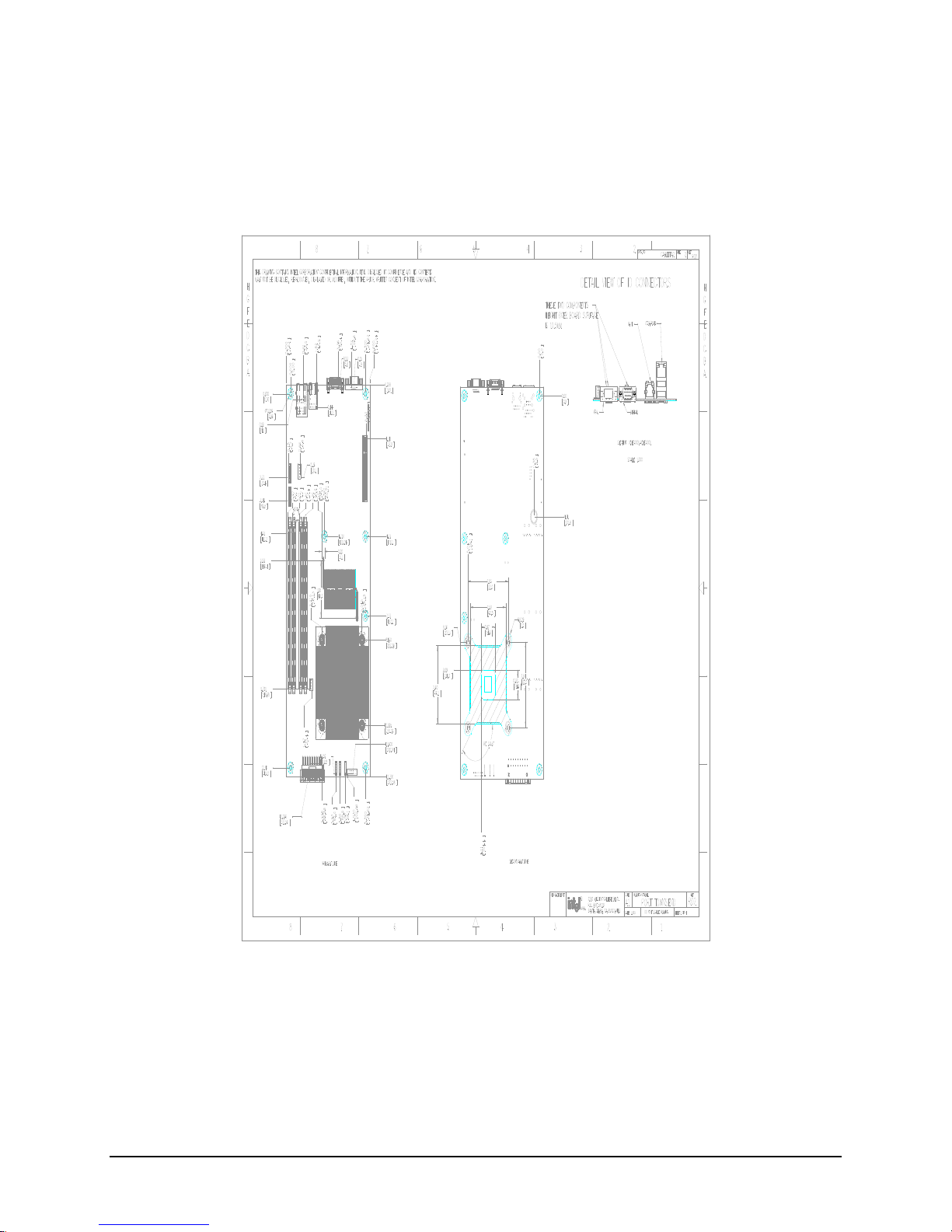
Design and Environmental Specifications Intel® Server Board S3000PT TPS
Revision 1.3
77
9.6 Mechanical Specifications
The following figure shows a mechanical drawing of the Intel® Server Board S3000PT.
Figure 28. Intel® Server Board S3000PT Mechanical Drawing
Page 86

Intel® Server Board S3000PT TPS Hardware Monitoring
78 Revision 1.3
10. Hardware Monitoring
10.1 Monitored Components
The Intel® Server Board S3000PT has an SMsC* SCH5027 or SCH5017 Super IO controller
with integrated hardware monitoring function. It provides basic server hardware monitoring
which alerts a system administrator if a hardware problem occurs on the board. It also has
implemented some fan speed control/monitor pins. The following table provides a list of
monitored headers and sensors on the board.
Table 65. Monitored Components
Item
Description
Voltage
VCCP_IN (PIN #127)
Monitors processor voltage
V1_IN (PIN #1)
Monitors +12Vin for system +12V supply
V2_IN (PIN #2)
Monitors +5Vin for system +5V supply
+2.5VTR_IN (PIN #128)
Monitors 1.5V Core power
VBAT (PIN #32)
Monitors Battery power
VTR1 (PIN #4)
Monitors +3.3Vin for system +3.3V supply
HVTR (PIN #122)
Monitors +3.3V_STBY for system +3.3V standby supply
Fan Speed
PWM1 (PIN #111)
Controls system fan 3 (J4K1)
PWM2 (PIN #110)
Controls system fan 2 (J4K2)
PWM3 (PIN #109)
Controls system fan 1 (J3K1)
TACH1 (PIN #115)
Monitors system fan 1 (J3K1)
TACH2 (PIN #114)
Monitors system fan 3 (J4K1)
TACH3 (PIN #113)
Monitors system fan 1 (J3K1)
TACH4 (PIN #112)
Monitors system fan 2 (J4K2)
TACHA (PIN #79)
Monitors system fan 2 (J4K2)
TACHB (PIN #77)
Monitors system fan 3 (J4K1)
SMsC* SCH5027 or SCH5017 embedded temperature sensor
PECI (PIN #119)
Monitors processor temperature through PECI interface
1
REMOTE1N/P(PIN
#125/6)
Monitors processor temperature
Temperature
REMOTE2N/P(PIN
#123/4)
Monitors system inlet air temperature through sensor (Q4K3)
near FP connector
1
Note: The SMsC* SCH5017 does not have a PECI interface.
Page 87

Hardware Monitoring Intel® Server Board S3000PT TPS
Revision 1.3
79
10.1.1 Fan Speed Control
Figure 29. Fan Speed Control Block Diagram
Page 88

Glossary Intel® Server Board S3000PT TPS
80 Revision 1.3
Glossary
This appendix contains important terms used in the preceding chapters. For ease of us e,
numeric entries are listed first (e.g., “82460GX”) with alpha entries following (e.g., “AGP 4x”).
Acronyms are then entered in their respective place, with non -acronyms following.
Term
Definition
ACPI
Advanced Configuration and Power Interface
ANSI
American National Standards Institute
AP
Application Processor
ASIC
Application Specific Integrated Circuit
ASR
Asynchronous Reset
BGA
Ball-grid Array
BIOS
Basic input/output system
Byte
8-bit quantity.
CMOS
In terms of this specification, this descri bes the PC-AT compatible region of battery -backed 128 bytes
of memory, which normally resides on the server board.
DCD
Data Carrier Detect
DMA
Direct Memory Access
DMTF
Distributed management Task Force
ECC
Error Correcting Code
EMC
Electromagnetic Co mpatibility
EPS
External Product Specification
ESCD
Extended System Configuration Data
FDC
Floppy Disk Controller
FIFO
First-In, First-Out
FRU
Field replaceable unit
GB
1024 MB.
GPIO
General purpose I/O
GUID
Globally Unique ID
Hz
Hertz (1 cycle/second)
HDG
Hardware Design Guide
I2C
Inter-integrated circuit bus
IA
Intel® architecture
ICMB
Intelligent Chassis Management Bus
IERR
Internal error
IMB
Inter Module Bus
IP
Internet Protocol
IRQ
Interrupt Request
ITP
In-target probe
KB
1024 bytes
KCS
Keyboard Controller Style
LAN
Local area network
LBA
Logical Block Address
LCD
Liquid crystal display
LPC
Low pin count
Page 89

Intel® Server Board S3000PT TPS Glossary
Revision 1.3
81
Term
Definition
LSB
Least Significant Bit
MB
1024 KB
MBE
Multi-Bit Error
Ms
milliseconds
MSB
Most Significant Bit
MTBF
Mean Time Between Failures
Mux
multiplexor
NIC
Network Interface Card
NMI
Non-maskable Interrupt
OEM
Original equipment manufacturer
Ohm
Unit of electrical resistance
PBGA
Pin Ball Grid Array
PERR
Parity Error
PIO
Programmable I/O
PMB
Private Management Bus
PMC
Platform Management Controller
PME
Power Management Event
PnP
Plug and Play
POST
Power-on Self Test
PWM
Pulse-Width Modulator
RAIDIOS
RAID I/O Steering
RAM
Random Access Memory
RI
Ring Indicate
RISC
Reduced instruction set computing
RMCP
Remote Management Control Protocol
ROM
Read Only Memory
RTC
Real Time Clock
SBE
Single-Bit Error
SCI
System Configuration Interrupt
SDR
Sensor Data Record
SDRAM
Synchronous Dynamic RAM
SEL
System event log
SERIRQ
Serialized Interrupt Requests
SERR
System Error
SM
Server Management
SMI
Server management interrupt. SMI is the highest priority non -maskable interrupt
SMM
System Management Mode
SMS
System Management Software
SNMP
Simple Network Management Protocol
SPD
Serial Presence Detect
SSI
Server Standards Infrastructure
TPS
Technical Product Specification
UART
Universal asynchronous receiver and transmitter
USB
Universal Serial Bus
VGA
Video Graphic Adapter
Page 90

Glossary Intel® Server Board S3000PT TPS
82 Revision 1.3
Term
Definition
VID
Voltage Identification
VRM
Voltage Regulator Module
Word
16-bit quantity
ZCR
Zero Channel RAID
Page 91

Intel® Server Board S3000PT TPS References
Revision 1.3
83
References
Advanced Configuration and Power Interface Specification , Revision 1.0b, February
1999, http://www.acpi.info/
Advanced Configuration and Power Interface Specification , Revision 2.0, July 2000,
http://www.acpi.info/
Advanced Configuration and Power Interface Specification , Revision 3.0, ,
http://www.acpi.info/
BIOS Boot Specification Version 1.01. Compaq Computer Corporation, Phoenix
Technologie Ltd., Intel Corporation. 1996, http://www.phoenix.com/resources/specs -
bbs101.pdf
El Torito CD-ROM Boot Specification, Version 1.0,
http://www.phoenix.com/resources/specs -cdrom.pdf
Extensible Firmware Interface Reference Specification , Version 1.1,
http://www.intel.com/technology/e fi/index.htm
Tiano EFI Shell EPS, Revision 0.10. Intel Corporation, 2002
EFI 1.1 Shell Commands Specification , v0.3, Available from:
EFI1.1ShellCommands.pdf, EFI sample implementation, revision 1.10.14.62,
http://developer.intel.com/technology/efi/main_sample.htm
IA-32e BIOS Writer's Guide , Revision 0.5, Intel Corporation
Platform Management FRU Information Storage Definition v1.0,
http://developer.intel.com/design/servers/ipmi
Hardware Design Guide for Microsoft Windows 2000 Server , Version 3.0,
http://www.microsoft.com/whdc/system/platform/pcdesign/desguide/serverdg.mspx#ESB
Application Note AP-485: Intel Processor Identification and the CPUID Function ,
http://www.intel.com/design/xeon/applnots/241 618.htm
Intelligent Platform Management Bus Specification , Version 1.0,
http://developer.intel.com/design/servers/ipmi/spec.htm
Intelligent Platform Management Interface Specificat ion, Version 1.5,
http://developer.intel.com/design/servers/ipmi/spec.htm
Intelligent Platform Management Interface Specification , Version 2.0,
http://developer.intel.com/design/servers/ipmi/spec.htm
Multiprocessor Specification , Revision 1.4, May 1997
Microsoft Headless Design Guidelines ,
http://www.microsoft.com/HWDEV/PLATFORM/server/headless/default.asp
PCI Local Bus Specification, Revision 3.0, http://www.pcisig.org/
PCI Local Bus Specification , Revision 2.2, http://www.pcisig.org/
Page 92

References Intel® Server Board S3000PT TPS
84 Revision 1.3
PCI BIOS Specification , Revision 2.1, http://www.pcisig.org/
PCI to PCI Bridge Specification , Revision 1.1, http://www.pcisig.org/
PCI Express Base Specification , Revision 1.0a, http://www.pcisig.org/
PCI Hot-Plug Specification, Revision 1.1, http://www.pcisig.org/
PCI IRQ Routing Table Specification , Revision 1.0, Microsoft Corporation
Plug and Play BIOS Specification , Revision 1.0a (relevant portions only),
http://www.microsoft.com/whdc/system/pnppwr/pnp/default.mspx
Sahalee Baseboard Management Controller Core External Product Specification for
Silverwood Systems, Intel Corporation
System Management BIOS Reference Specification, Version 2.4,
http://www.dmtf.org/standards/smbios
ACPI Static Resource Affinity Table, Version 1.2,
http://www.microsoft.com/whdc/hwdev/platform/proc/SRAT.mspx
SYSID BIOS Support Interface Requirement Specification , Version 1.2
Intel® Platform Innovation Framework for EFI Firmware Volume Specification , Revision
0.9, Intel Corporation, 2004, ftp://download.intel.com/technology/framework/docs/Fv.pdf
Universal Host Controller Interface Design Guid e,
http://developer.intel.com/design/USB/UHCI11D.htm
Universal Serial Bus Revision 1.1 Specification, http://www.usb.org/developers/docs
Universal Serial Bus Revision 2.0 Specification, http://www.usb.org/developers/docs
Wired For Management Baseline Specification , Revision 2.0,
http://www.intel.com/labs/manage/wfm/wfmspecs.htm
DMTF Systems Standard Groups Definition
 Loading...