

Page 1

Intel® Server Board S2600WF
Product Family
Technical Product Specification
An overview of product features, functions, architecture, and support specifications.
Rev 1.1
October 2017
Intel® Server Products and Solutions
Page 2

Intel® Server Board S2600WF Product Family Technical Product Specification
<Blank Page>
Page 3

Intel® Server Board S2600WF Product Family Technical Product Specification
Date
Revision
Description of Change
July 2017
1.0
Production Release
Updated all tables from Appendix B and Appendix C
Added S2600WFQ Architecture Block Diagram
October 2017 1.1
Document Revision History
Updated Product Architecture Overview
Updated S2600WF Architecture Block Diagram
Added Intel® QAT information:
• Server Board Product Family Feature Set
• Architecture Board Diagram
• Added 6.1 section Intel® QuickAssist Technology Support
•
3
Page 4

Intel® Server Board S2600WF Product Family Technical Product Specification
Disclaimers
Intel technologies’ features and benefits depend on system configuration and may require enabled hardware, software, or service
activation. Learn more at Intel.com, or from the OEM or retailer.
You may not use or facilitate the use of this document in connection with any infringement or other legal analysis concerning Intel
products described herein. You agree to grant Intel a non-exclusive, royalty-free license to any patent claim thereafter drafted which
includes subject matter disclosed herein.
No license (express or implied, by estoppel or otherwise) to any intellectual property rights is granted by this document.
The products described may contain design defects or errors known as errata which may cause the product to deviate from
published specifications. Current characterized errata are available on request.
Intel disclaims all express and implied warranties, including without limitation, the implied warranties of merchantability, fitness
for a particular purpose, and non-infringement, as well as any warranty arising from course of performance, course of dealing, or
usage in trade.
Copies of documents which have an order number and are referenced in this document may be obtained by calling 1-800-548-4725
or by visiting www.intel.com/design/literature.htm
Intel, the Intel logo, Xeon, and Intel Xeon Phi are trademarks of Intel Corporation or its subsidiaries in the U.S. and/or other countries.
*Other names and brands may be claimed as the property of others.
Copyright © 2017 Intel Corporation. All rights reserved.
.
4
Page 5

Intel® Server Board S2600WF Product Family Technical Product Specification
Table of Contents
1. Introduction ............................................................................................................................................................... 13
1.1 Intel Server Board Use Disclaimer ..................................................................................................................... 14
1.2 Product Errata .......................................................................................................................................................... 14
2. Server Board Family Overview .............................................................................................................................. 15
2.1 Server Board Family Feature Set ....................................................................................................................... 17
2.2 Server Board Component/Feature Identification ......................................................................................... 19
2.3 Server Board Mechanical Drawings .................................................................................................................. 23
2.4 Product Architecture Overview .......................................................................................................................... 27
2.5 System Software Stack ......................................................................................................................................... 28
2.5.1 Hot Keys Supported During POST .................................................................................................................... 29
2.5.2 Field Replaceable Unit (FRU) and Sensor Data Record (SDR) Data ........................................................ 31
3. Processor Support .................................................................................................................................................... 33
3.1 Processor Socket and Processor Heat Sink Module (PHM) Assembly .................................................. 33
3.2 Processor Thermal Design Power (TDP) Support ........................................................................................ 35
3.3 Intel® Xeon® Processor Scalable Family Overview ....................................................................................... 36
3.3.1 Supported Technologies ...................................................................................................................................... 37
3.3.2 Intel® Xeon® Processor Scalable Family with Integrated Intel® Omni-Path Fabric ............................ 39
3.3.3 Intel®Omni-Path IFT Carrier Accessory Kits ................................................................................................... 41
3.4 Processor Population Rules ................................................................................................................................ 44
3.5 Processor Initialization Error Summary ........................................................................................................... 44
4. System Memory ........................................................................................................................................................ 47
4.1 Memory Subsystem Architecture ...................................................................................................................... 47
4.2 Supported Memory ................................................................................................................................................ 48
4.3 Memory Slot Identification and Population Rules ....................................................................................... 48
4.3.1 DIMM Population Guidelines for Best Performance .................................................................................... 50
4.4 Memory RAS Features ........................................................................................................................................... 51
4.4.1 DIMM Populations Rules and BIOS Setup for Memory RAS ..................................................................... 52
5. PCIe* Support ............................................................................................................................................................ 53
5.1.1 PCIe* Enumeration and Allocation .................................................................................................................... 53
5.1.2 Non-Transparent Bridge ....................................................................................................................................... 53
6. System I/O ................................................................................................................................................................. 55
6.1 Intel® QuickAssist Technology (Intel® QAT) Support .................................................................................. 55
6.2 PCIe* Add-in Card Support .................................................................................................................................. 56
6.2.1 Riser Slot #1 and Riser Slot #2 Riser Card Options ..................................................................................... 57
6.2.2 Riser Slot #3 Riser Card Option (iPC – A2UX8X4RISER) ............................................................................ 59
6.2.3 Intel® Ethernet Network Adapter for OCP* Support .................................................................................... 59
6.2.4 Intel® Integrated RAID Module Support .......................................................................................................... 61
6.3 Onboard Storage Subsystem .............................................................................................................................. 61
6.3.1 M.2 SSD Support ..................................................................................................................................................... 61
5
Page 6

Intel® Server Board S2600WF Product Family Technical Product Specification
6.3.2 Onboard PCIe* OCuLink Connectors ............................................................................................................... 63
6.3.3 Intel® Volume Management Device (Intel® VMD) for NVMe* .................................................................... 63
6.3.4 Intel® Virtual RAID on Chip (Intel® VROC) For NVMe* ................................................................................. 66
6.3.5 Onboard SATA Support ........................................................................................................................................ 67
6.3.6 Onboard SATA RAID Options ............................................................................................................................. 69
6.4 Rear External RJ45 Connector Overview ........................................................................................................ 72
6.4.1 RJ45 Dedicated Management Port ................................................................................................................... 72
6.4.2 RJ45 Network Interface Connectors (Intel® Server Board S2600WFT only) ....................................... 73
6.5 Serial Port Support ................................................................................................................................................. 73
6.6 USB Support ............................................................................................................................................................. 75
6.6.1 External USB 3.0 Connector ................................................................................................................................ 75
6.6.2 Internal USB 2.0 Type-A Connector ................................................................................................................. 75
6.6.3 Front Panel USB 3.0 Connector ......................................................................................................................... 75
6.6.4 Front Panel USB 2.0 Connector ......................................................................................................................... 76
6.7 Video Support .......................................................................................................................................................... 77
6.7.1 Onboard Video Connectors ................................................................................................................................. 78
6.7.2 Onboard Video and Add-In Video Adapter Support................................................................................... 79
6.7.3 Dual Monitor Support ............................................................................................................................................ 79
7. Onboard Connector/Header Pinout Definition ................................................................................................. 80
7.1 Power Connectors .................................................................................................................................................. 80
7.1.1 Main Power ............................................................................................................................................................... 80
7.1.2 Hot Swap Backplane Power Connector ........................................................................................................... 82
7.1.3 Riser Card Supplemental 12-V Power Connectors...................................................................................... 83
7.1.4 Peripheral Power Connector ............................................................................................................................... 84
7.2 Front Control Panel Headers and Connectors .............................................................................................. 85
7.2.1 Front Panel LED and Control Button Features Overview .......................................................................... 86
7.3 System Fan Connectors ........................................................................................................................................ 88
7.4 Management Connectors ..................................................................................................................................... 89
8. Basic and Advanced Server Management Features .......................................................................................... 91
8.1 Dedicated Management Port .............................................................................................................................. 92
8.2 Embedded Web Server ......................................................................................................................................... 92
8.3 Advanced Management Feature Support ....................................................................................................... 94
8.3.1 Keyboard, Video, Mouse (KVM) Redirection .................................................................................................. 94
8.3.2 Media Redirection ................................................................................................................................................... 95
8.3.3 Remote Console ...................................................................................................................................................... 96
8.3.4 Performance ............................................................................................................................................................. 96
9. Light Guided Diagnostics ........................................................................................................................................ 97
9.1 System ID LED .......................................................................................................................................................... 98
9.2 System Status LED.................................................................................................................................................. 98
9.3 BMC Boot/Reset Status LED Indicators ........................................................................................................... 99
9.4 Post Code Diagnostic LEDs ............................................................................................................................... 100
6
Page 7

Intel® Server Board S2600WF Product Family Technical Product Specification
9.5 Fan Fault LEDs ...................................................................................................................................................... 100
9.6 Memory Fault LEDs ............................................................................................................................................. 100
9.7 CPU Fault LEDs ..................................................................................................................................................... 100
10. System Security ...................................................................................................................................................... 101
10.1 Password Protection ........................................................................................................................................... 101
10.1.1 Password Setup .................................................................................................................................................... 101
10.1.2 System Administrator Password Rights ....................................................................................................... 102
10.1.3 Authorized System User Password Rights and Restrictions .................................................................. 102
10.2 Front Panel Lockout ............................................................................................................................................ 103
10.3 Trusted Platform Module (TPM) Support .................................................................................................... 103
10.3.1 TPM Security BIOS ............................................................................................................................................... 103
10.3.2 Physical Presence ................................................................................................................................................ 104
10.3.3 TPM Security Setup Options ............................................................................................................................ 104
10.4 Intel® Trusted Execution Technology ............................................................................................................ 104
11. Reset and Recovery Jumpers ............................................................................................................................... 105
11.1 BIOS Default Jumper Block .............................................................................................................................. 105
11.2 Password Clear Jumper Block ......................................................................................................................... 106
11.3 Intel® Management Engine (Intel® ME) Firmware Force Update Jumper Block ............................... 106
11.4 BMC Force Update Jumper Block................................................................................................................... 107
11.5 BIOS Recovery Jumper ...................................................................................................................................... 107
12. Platform Management ........................................................................................................................................... 109
12.1 Management Feature Set Overview ............................................................................................................... 109
12.1.1 IPMI 2.0 Features Overview .............................................................................................................................. 109
12.1.2 Non-IPMI Features Overview ........................................................................................................................... 109
12.2 Platform Management Features and Functions ........................................................................................ 111
12.2.1 Power Subsystem ................................................................................................................................................ 111
12.2.2 Advanced Configuration and Power Interface (ACPI) .............................................................................. 111
12.2.3 System Initialization ............................................................................................................................................ 112
12.2.4 Watchdog Timer ................................................................................................................................................... 112
12.2.5 System Event Log (SEL) ..................................................................................................................................... 112
12.3 Sensor Monitoring ............................................................................................................................................... 113
12.3.1 Sensor Re-arm Behavior .................................................................................................................................... 113
12.3.2 Thermal Monitoring ............................................................................................................................................ 113
12.3.3 Standard Fan Management .............................................................................................................................. 114
12.3.4 Memory Thermal Management ....................................................................................................................... 116
12.3.5 Power Management Bus (PMBus*) ................................................................................................................. 117
12.3.6 Component Fault LED Control ........................................................................................................................ 118
Appendix A. Integration and Usage Tips ............................................................................................................... 119
Appendix B. POST Code Diagnostic LED Decoder .............................................................................................. 120
B.1. Early POST Memory Initialization MRC Diagnostic Codes .................................................................. 121
B.2. BIOS POST Progress Codes .............................................................................................................................. 123
7
Page 8

Intel® Server Board S2600WF Product Family Technical Product Specification
Appendix C. POST Code Errors ................................................................................................................................ 126
C.1. POST Error Beep Codes ..................................................................................................................................... 133
Appendix D. Statement of Volatile Memory Components ................................................................................ 134
Appendix E. Supported Intel® Server Systems..................................................................................................... 136
E.1. Intel® Server System R1000WF Product Family ........................................................................................ 136
E.2. Intel® Server System R2000WF Product Family ........................................................................................ 138
Appendix F. Glossary ................................................................................................................................................. 140
8
Page 9

Intel® Server Board S2600WF Product Family Technical Product Specification
List of Figures
Figure 1. Intel® Server Board S2600WF .................................................................................................................................... 15
Figure 2. Intel® Server Board S2600WF with available onboard options ...................................................................... 16
Figure 3. Server board component/feature identification .................................................................................................. 19
Figure 4. Intel® Server Board S2600WF external I/O connector layout ......................................................................... 20
Figure 5. Intel® Light Guided Diagnostics - DIMM fault LEDs ............................................................................................. 20
Figure 6. Intel® Light Guided Diagnostic – LED identification............................................................................................. 21
Figure 7. Board configuration and recovery jumpers ........................................................................................................... 22
Figure 8. Intel® Server Board S2600WF primary side keepout zone ............................................................................... 23
Figure 9. Intel® Server Board S2600WF hole and component positions ....................................................................... 24
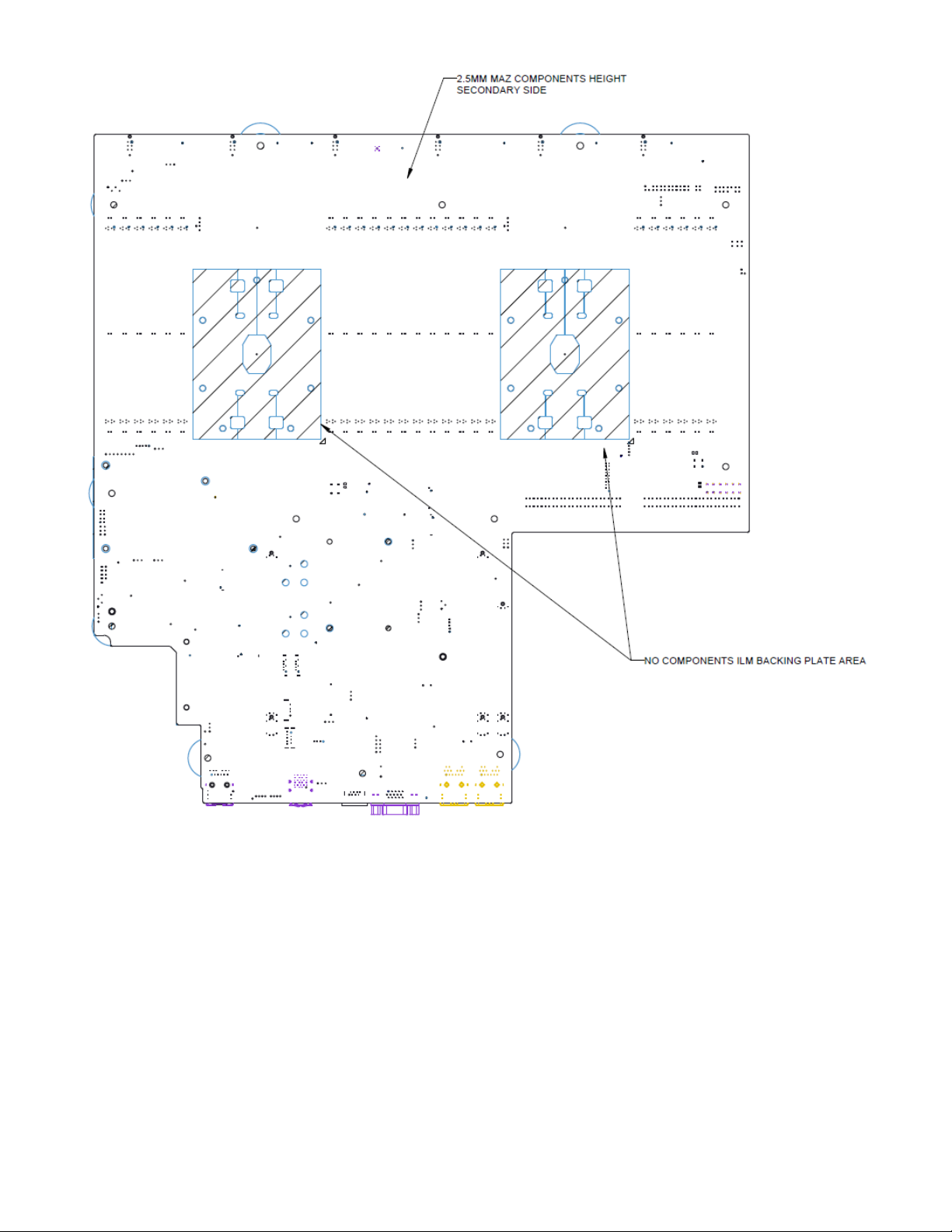
Figure 10. Intel® Server Board S2600WF secondary side keepout zone ....................................................................... 25
Figure 11. Intel® Server Board S2600WF primary side height restrictions ................................................................... 26
Figure 12. Intel® Server Board S2600WF product family architectural block diagram ............................................. 27
Figure 13. Intel® Server Board S2600WFQ architectural block diagram ....................................................................... 28
Figure 14. Processor heat sink module (PHM) components and processor socket reference diagram .............. 33
Figure 15. Processor attached to the processor heat sink installation ........................................................................... 34
Figure 16. PHM to CPU socket orientation and alignment features ................................................................................ 34
Figure 17. Processor socket assembly and protective cover ............................................................................................. 35
Figure 18. Intel® OP HFI connector location ............................................................................................................................ 40
Figure 19. Multi-chip package (MCP) ......................................................................................................................................... 40
Figure 20. Dual processor configurations with one or two fabric processors .............................................................. 41
Figure 21. Intel® Omni-Path IFT Carrier Accessory Kit components ............................................................................... 42
Figure 22. Server board sideband connectors ........................................................................................................................ 42
Figure 23. IFT carrier board – rear view ..................................................................................................................................... 43
Figure 24. Memory subsystem architecture ............................................................................................................................ 47
Figure 25. Intel® Server Board S2600WF memory slot layout .......................................................................................... 48
Figure 26. DIMM population diagram ........................................................................................................................................ 50
Figure 27. Two systems connected through an NTB ............................................................................................................ 54
Figure 28. Intel® QAT cable ........................................................................................................................................................... 56
Figure 29. PCIe* add-in card support ......................................................................................................................................... 57
Figure 30. 1U one-slot PCIe* riser card (iPC – F1UL16RISER3APP) ................................................................................. 58
Figure 31. 2U three-slot PCIe* riser card (iPC – A2UL8RISER2) ........................................................................................ 58
Figure 32. 2U two-slot PCIe* riser card (iPC – A2UL16RISER2) ......................................................................................... 59
Figure 33. Low profile riser card (iPC – A2UX8X4RISER) ..................................................................................................... 59
Figure 34. Intel® Ethernet Network Adapter for OCP* connector ..................................................................................... 60
Figure 35. Intel® Integrated RAID module ................................................................................................................................ 61
Figure 36. M.2 storage device connectors ................................................................................................................................ 62
Figure 37. Onboard OCuLink connectors ................................................................................................................................. 63
Figure 38. NVMe* storage bus event/error handling ............................................................................................................ 63
Figure 39. Intel® VMD support disabled in BIOS setup ........................................................................................................ 65
9
Page 10

Intel® Server Board S2600WF Product Family Technical Product Specification
Figure 40. Intel® VMD support enabled in BIOS setup ......................................................................................................... 65
Figure 41. Intel® VROC basic architecture overview .............................................................................................................. 66
Figure 42. Intel® VROC upgrade key ........................................................................................................................................... 67
Figure 43. Onboard SATA port connector identification..................................................................................................... 68
Figure 44. BIOS setup Mass Storage Controller Configuration screen ........................................................................... 70
Figure 45. Intel® ESRT2 SATA RAID-5 upgrade key (iPN – RKSATA4R5) ....................................................................... 71
Figure 46. Rear external RJ45 connectors ............................................................................................................................... 72
Figure 47. RJ45 connector LEDs.................................................................................................................................................. 72
Figure 48. RJ45 Serial-A pin orientation ................................................................................................................................... 73
Figure 49. J4A2 Jumper block for Serial-A pin 7 configuration ....................................................................................... 74
Figure 50. Serial-B connector (internal) .................................................................................................................................... 74
Figure 51. External USB 3.0 ports ............................................................................................................................................... 75
Figure 52. Internal USB 2.0 type-A connector ........................................................................................................................ 75
Figure 53. Front panel USB 3.0 connector ............................................................................................................................... 76
Figure 54. Front panel USB 2.0 connector ............................................................................................................................... 77
Figure 55. Rear external video connector ................................................................................................................................. 78
Figure 56. Front panel video connector .................................................................................................................................... 78
Figure 57. “MAIN PWR 1” and “MAIN PWR 2” connectors .................................................................................................. 80
Figure 58. Hot swap backplane power connector ................................................................................................................. 82
Figure 59. Riser slot auxiliary power connectors ................................................................................................................... 83
Figure 60. High power add-in card 12-V auxiliary power cable option .......................................................................... 84
Figure 61. Peripheral power connector ..................................................................................................................................... 84
Figure 62. Front control panel connectors .............................................................................................................................. 85
Figure 63. Example front control panel view (for reference purposes only) ................................................................ 85
Figure 64. Dual-rotor fixed mount fan pin connector orientation .................................................................................... 88
Figure 65. Hot swap fan connector pin orientation ............................................................................................................... 88
Figure 66. Fan connector locations ............................................................................................................................................ 89
Figure 67.Hot swap backplane connector locations ............................................................................................................. 89
Figure 68. Intel® RMM4 Lite activation key installation ........................................................................................................ 91
Figure 69. Dedicated managment port...................................................................................................................................... 92
Figure 70. Onboard diagnostic and fault LED placement ................................................................................................... 97
Figure 71.DIMM fault LED placement ........................................................................................................................................ 98
Figure 72. BIOS setup Security tab .......................................................................................................................................... 101
Figure 73. Reset and recovery jumper block location ....................................................................................................... 105
Figure 74. High-level fan speed control process ................................................................................................................ 116
Figure 75. Onboard POST diagnostic LED location and definition ............................................................................... 120
Figure 76. Intel® Server System R1000WF product family .............................................................................................. 136
Figure 77. Intel® Server System R2000WF product family .............................................................................................. 138
10
Page 11

Intel® Server Board S2600WF Product Family Technical Product Specification
List of Tables
Table 1. Reference documents .................................................................................................................................................... 13
Table 2. Intel® Server Board S2600WF product family feature set.................................................................................. 17
Table 3. POST hot keys................................................................................................................................................................... 29
Table 4. Intel® Xeon® processor Scalable family feature comparison............................................................................. 36
Table 5. Intel® Xeon® processor Scalable family with integrated Intel® OP HFI features.......................................... 39
Table 6. IFT carrier LED functionality ......................................................................................................................................... 43
Table 7. Power level classification for QSFP+ modules....................................................................................................... 43
Table 8. Supported processor mixing – fabric vs non-fabric processors ...................................................................... 43
Table 9. Mixed processor configurations error summary ................................................................................................... 45
Table 10.DDR4 RDIMM and LRDIMM support ......................................................................................................................... 48
Table 11. Memory RAS features .................................................................................................................................................. 51
Table 12. CPU - PCIe* port routing ............................................................................................................................................. 53
Table 13. Riser slot #1 PCIe* root port mapping ................................................................................................................... 57
Table 14. Riser slot #2 PCIe* root port mapping ................................................................................................................... 57
Table 15. Riser slot #3 PCIe* root port mapping ................................................................................................................... 57
Table 16. One-slot PCIe* riser card slot description ............................................................................................................. 58
Table 17. Three-slot PCIe* riser card slot description ......................................................................................................... 58
Table 18. Two-slot PCIe* riser card slot description ............................................................................................................ 59
Table 19. Low profile riser card slot description .................................................................................................................... 59
Table 20. Supported Intel® Ethernet Network Adapters for OCP* ................................................................................... 60
Table 21. Intel® VROC upgrade key options ............................................................................................................................ 67
Table 22. SATA and sSATA controller feature support ....................................................................................................... 68
Table 23. SATA and sSATA controller BIOS setup utility options .................................................................................... 69
Table 24. External RJ45 NIC port LED definition ................................................................................................................... 72
Table 25.Serial-A connector pinout ........................................................................................................................................... 73
Table 26. Serial-B connector pinout .......................................................................................................................................... 74
Table 27. Front panel USB 2.0/3.0 connector pinout (“FP_USB_2.0/ 3.0”) ................................................................... 76
Table 28. Front panel USB 2.0 connector pinout ("FP_USB_2.0_5-6 ") .......................................................................... 77
Table 29. Supported video resolutions ..................................................................................................................................... 77
Table 30. Front panel video connector pinout ("FP VIDEO").............................................................................................. 78
Table 31. Main power (slot 1) connector pinout (“MAIN PWR 1”) .................................................................................... 81
Table 32. Main power (slot 2) connector pinout (“MAIN PWR 2”) .................................................................................... 81
Table 33. Hot swap backplane power connector pinout (“HSBP PWR”) ........................................................................ 82
Table 34. Riser slot auxiliary power connector pinout ("OPT_12V_PWR”) ................................................................... 83
Table 35. Peripheral drive power connector pinout ("Peripheral_PWR") ...................................................................... 84
Table 36. Front panel control button and LED support ...................................................................................................... 85
Table 37. 30-pin front panel connector pinouts .................................................................................................................... 86
Table 38. Power/sleep LED functional states ......................................................................................................................... 86
Table 39. NMI signal generation and event logging .............................................................................................................. 87
11
Page 12

Intel® Server Board S2600WF Product Family Technical Product Specification
Table 40. Dual-rotor fixed mount fan connector pinout ..................................................................................................... 88
Table 41. Hot swap fan connector pinout ................................................................................................................................ 88
Table 42. Hot swap backplane I
Table 43. Hot swap backplane I
2
C connector – SMBUS 3-pin (J5C3) ............................................................................. 89
2
C connector – SMBUS 4-pin (J1K1) ............................................................................. 90
Table 44. IPMB – SMBUS 4-pin (J1C3) ...................................................................................................................................... 90
Table 45. Intel® Remote Management Module 4 (Intel® RMM4) options ....................................................................... 91
Table 46. Basic and advanced server management features overview .......................................................................... 91
Table 47. System status LED states ............................................................................................................................................ 99
Table 48. BMC boot/reset status LED indicators ................................................................................................................... 99
Table 49. Power control sources .............................................................................................................................................. 111
Table 50. ACPI power states ...................................................................................................................................................... 111
Table 51. Component fault LEDs ............................................................................................................................................. 118
Table 52. POST progress code LED example ....................................................................................................................... 120
Table 53. MRC progress codes .................................................................................................................................................. 121
Table 54. MRC fatal error codes ............................................................................................................................................... 122
Table 55. POST progress codes ............................................................................................................................................... 123
Table 56. POST error messages and handling .................................................................................................................... 127
Table 57. POST error beep codes ............................................................................................................................................ 133
Table 58. Integrated BMC beep codes ................................................................................................................................... 133
Table 59. Volatile and non-volatile components ............................................................................................................... 135
Table 60. Intel® Server System R1000WF product family feature set ......................................................................... 137
Table 61. Intel® Server System R2000WF product family feature set ......................................................................... 138
12
Page 13

Intel® Server Board S2600WF Product Family Technical Product Specification
Document Title
Document Classification
Intel® Servers System BMC Firmware EPS for Intel® Xeon® processor Scalable Family
Intel Confidential
Intel® Server System BIOS EPS for Intel® Xeon® processor Scalable Family
Intel Confidential
Intel® C62x Series Chipset Platform Controller Hub External Design Specification
Intel Confidential
Intel® Xeon® processor Scalable family Server Processor External Design Specification
Doc ID: 546831, 546833, 546834, 546832
Intel® Ethernet Connection X557-AT2 Product Brief
Public
1. Introduction
This Technical Product Specification (TPS) provides a high level overview of the features, functions,
architecture and support specifications of the Intel® Server Board S2600WF product family.
Note: This document includes several references to Intel websites where additional product information can
be downloaded. However, these public Intel sites will not include content for products in development.
Content for these products will be available on the public Intel web sites after their public launch.
Note: Some of the documents listed in the following table are classified as “Intel Confidential”. These
documents are made available under a Non-Disclosure Agreement (NDA) with Intel and must be ordered
through your local Intel
For more in-depth technical information, refer to the documents in Table 1.
representative.
Table 1. Reference documents
Intel Confidential
13
Page 14

Intel® Server Board S2600WF Product Family Technical Product Specification
1.1 Intel Server Board Use Disclaimer
Intel Corporation server boards support add-in peripherals and contain a number of high-density VLSI and
power delivery components that need adequate airflow to cool. Intel ensures through its own chassis
development and testing that when Intel
system will meet the intended thermal requirements of these components. It is the responsibility of the
system integrator who chooses not to use Intel developed server building blocks to consult vendor
datasheets and operating parameters to determine the amount of airflow required for their specific
application and operating environment. Intel Corporation cannot be held responsible if components fail or
the server board does not operate correctly when used outside any of its published operating or nonoperating limits.
server building blocks are used together, the fully integrated
1.2 Product Errata
Shipping product may have features or functionality that may deviate from published specifications. These
deviations are generally discovered after the product has gone into formal production. Intel terms these
deviations as product Errata. Known product Errata will be published in the Monthly Specification Update for
the given product family which can be downloaded from http://www.intel.com/support
.
14
Page 15
Intel® Server Board S2600WF Product Family Technical Product Specification
2. Server Board Family Overview
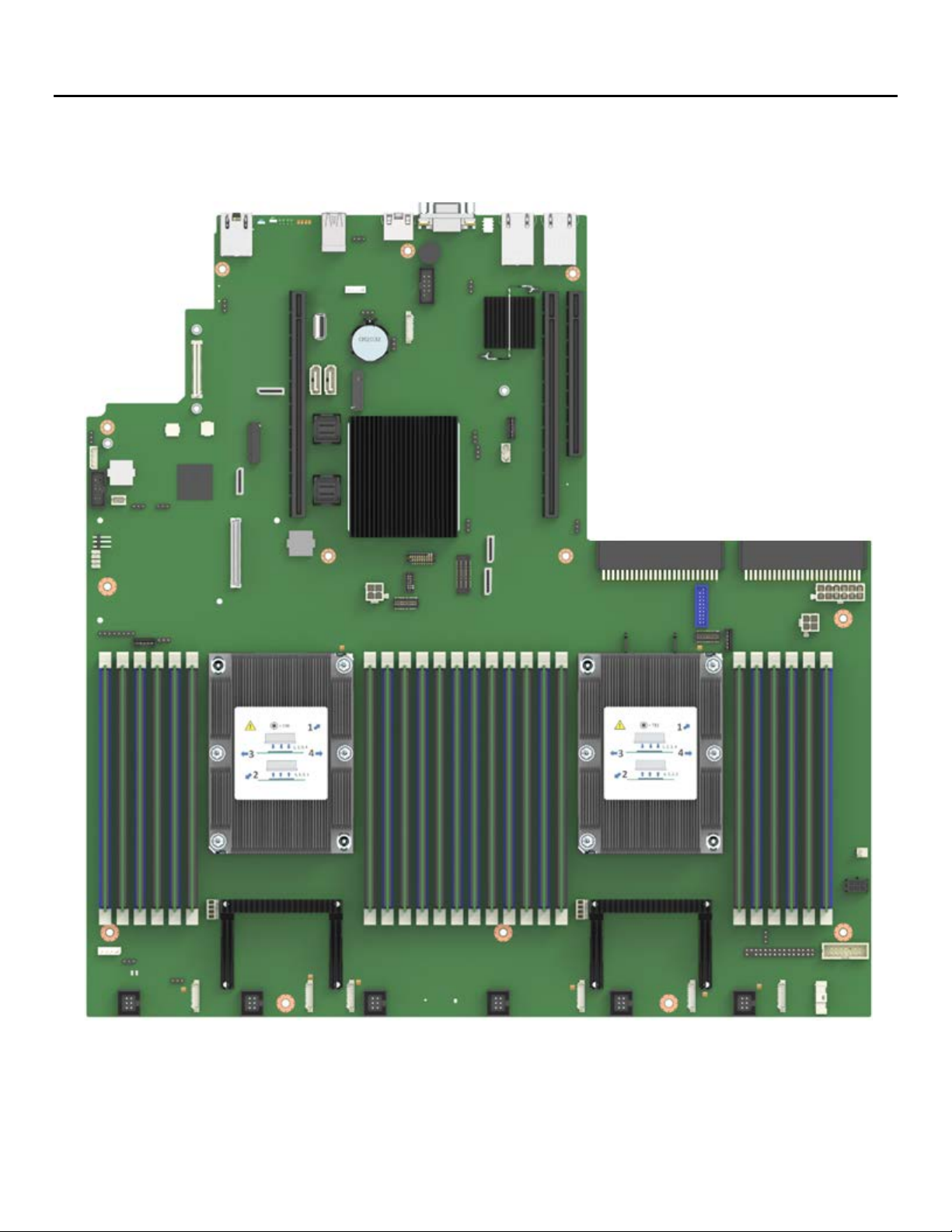
The Intel® Server Board S2600WF is a monolithic printed circuit board assembly with features that are
intended for high density 1U and 2U rack mount servers. This server board is designed to support the Intel®
Xeon® processor Scalable family. Previous generation Intel® Xeon® processors are not supported.
Figure 1. Intel® Server Board S2600WF
15
Page 16
Intel® Server Board S2600WF Product Family Technical Product Specification
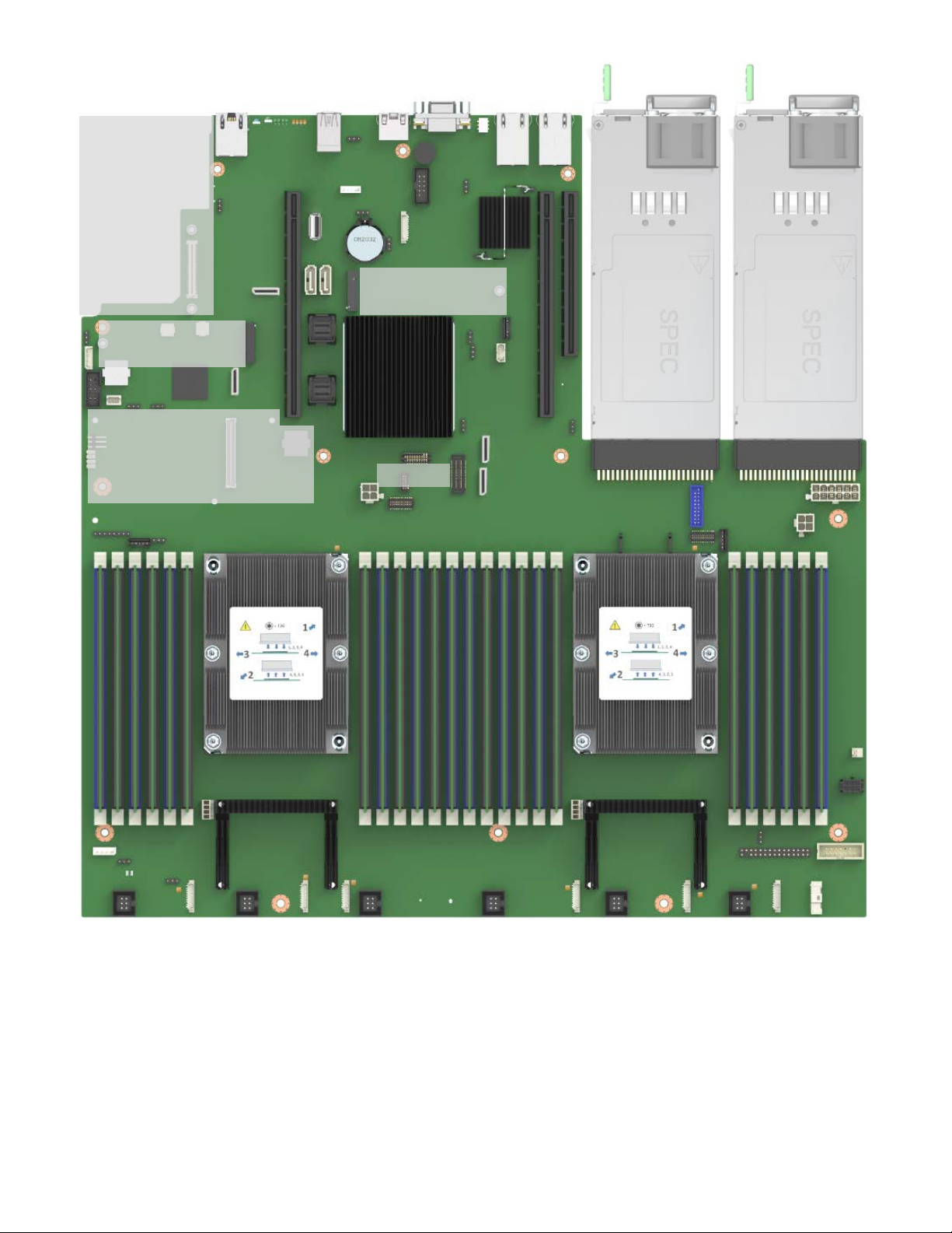
Support for KR
based OCP
module options
80 mm M.2
PCIe*/SATA
Support for Intel®
Integrated SAS RAID
module options
80 mm M.2
PCIe*/SATA
TPM 2.0
Support for dual hot swap
power supply modules
1+0, 1+1, 2+0 configurations
Figure 2. Intel® Server Board S2600WF with available onboard options
16
Page 17

Intel® Server Board S2600WF Product Family Technical Product Specification
Intel® Server
Board Feature
S2600WFT
S2600WF0
S2600WFQ
Processor
(2) – LGA3647-0 (Socket P) processor sockets
Design Power (TDP). See the appropriate Intel® System TPS for maximum supported TDP.
Memory
• (24) – total DIMM slots
• DDR4 standard voltage of 1.2 V
Intel® C62x Series
Chipset
Intel® C624 Chipset
Intel® C624 Chipset
Intel® C628 Chipset
Intel® Quick Assist
Technology
No
No
Yes
Intel® Omni-Path
Fabric
Yes
Yes
Yes
Onboard LAN
Dual Port RJ45 10 GbE
No
No
OCP Module
• Dual Port 10Gb RJ45 –
• Quad Port 1Gb RJ45 –
iPC X527DA2OCPG1P5
• Quad Port 1Gb RJ45 –
iPC X527DA2OCPG1P5
Intel® Integrated
SAS Module
Yes
Yes
Yes
Onboard PCIe*
• (4) – OCuLink connectors
support (accessory option)
• (4) – OCuLink connectors
support (accessory option)
• (2) – OCuLink connectors
(accessory option)
2.1 Server Board Family Feature Set
Table 2 lists the server board product family feature set.
Table 2. Intel® Server Board S2600WF product family feature set
•
• Supports (1) or (2) processors from the Intel® Xeon® processor Scalable family (Platinum, Gold, Silver, and
Bronze). Note: Previous generation Intel® Xeon® processors are not supported.
• Maximum supported Thermal Design Power (TDP) of up to 205 W (board only)
• Note: Intel® Server Systems based on this server board family may support a lower maximum Thermal
o (12) – DIMM slots per processor, (6) – memory channels per processor
o (2) – DIMMs per channel
• Registered DDR4 (RDIMM), Load Reduced DDR4 (LRDIMM)
• Memory capacity
o Up to 1.5 TB for Gold and Platinum CPUs
o Up to 768 GB for Silver and Bronze CPUs
• Memory data transfer rates
o Up to 2666 MT/s at (1) and (2) DIMMs per channel (dependent on processor)
Support
NVMe
iPC 557T2OCPG1P5
• Dual Port SFP+ –
iPC 527DA2OCPG1P5
• Intel® VMD support
• Intel® RSTe/Intel® VROC
iPC I357T4OCPG1P5
• Quad Port SFP+ –
iPC X527DA4OCPG1P5
• Dual Port 10Gb RJ45 –
iPC X557T2OCPG1P5
• Dual Port SFP+ –
• Intel® VMD support
• Intel® RSTe/Intel® VROC
iPC I357T4OCPG1P5
• Quad Port SFP+ –
iPC X527DA4OCPG1P5
• Dual Port 10Gb RJ45 –
iPC X557T2OCPG1P5
• Dual Port SFP+ –
• Intel® VMD support
• Intel® RSTe/Intel® VROC support
17
Page 18

Intel® Server Board S2600WF Product Family Technical Product Specification
Intel® Server
Onboard SATA
• 12 x SATA 6 Gbps ports (6 Gb/s, 3 Gb/s and 1.5 Gb/s transfer
• 4 x SATA 6 Gbps ports (6 Gb/s, 3
Riser Card
Concurrent support for up to three riser cards
• Riser #3 (2U systems only) – PCIe* 3.0 (CPU 2 x12) – 2 slot riser card available
Video
• Integrated 2D video controller
• (1) – 14-pin internal connector for optional front panel video support
USB
• (3) – external USB 3.0 ports
(1) – internal 10-pin connector for optional 2x USB 2.0 port front panel support
Serial Port
• (1) – external RJ-45 serial-A port connector
• (1) – internal DH-10 serial-B port header for optional front or rear serial port support
Server
• Integrated baseboard management controller, IPMI 2.0 compliant
Advanced server management via Intel® RMM4 Lite – iPC AXXRMM4LITE2 (accessory option)
Security
• Trusted platform module 2.0 (Rest of World) – iPC AXXTPMENC8BPP (accessory option)
• Trusted platform module 2.0 (China Version) – iPC AXXTPME8BPP (accessory option)
System Fan
• (6) – system fans supported in two different connector formats: hot swap (2U) and cabled (1U)
configuration
Board Feature S2600WFT S2600WF0 S2600WFQ
rates supported)
o (2) – single port 7-pin SATA connectors
o (2) – M.2 connectors – SATA / PCIe*
o (2) – 4-port mini-SAS HD (SFF-8643) connectors
• Embedded SATA Software RAID
o Intel® RSTe 5.0
o Intel® Embedded Server RAID Technology 2 1.60 with
optional RAID 5 key support
• Riser #1 – PCIe* 3.0 x24 (CPU1 x16, CPU2 x8) – 2 and 3 slot riser card options available
• Riser #2 – PCIe* 3.0 x24 (CPU2 x24) – 2 and 3 slot riser card options available
• 16MB of DDR4 video memory
• (1) – DB-15 external connector
• (1) – internal type-A USB 2.0 port
• (1) – internal 20-pin connector for optional 2x USB 3.0 port front panel support
•
Gb/s and 1.5 Gb/s transfer rates
supported)
o (2) – single port 7-pin SATA
connectors
o (2) – M.2 connectors –
SATA/PCIe*
• Embedded SATA Software RAID
o Intel® RSTe 5.0
Note: 4-port mini-SAS HD connectors
are present on S2600WFQ but are not
configured as SATA; these cables are
used only for Intel® QAT.
Management
• Support for Intel® Server Management software
• Dedicated onboard RJ45 management port
•
o (6) – 10-pin managed system fan headers (sys_fan 1-6) – used for 1U system configuration
o (6) – 6-pin hot swap capable managed system fan connectors (sys_fan 1-6) – used for 2U system
18
Page 19
Intel® Server Board S2600WF Product Family Technical Product Specification
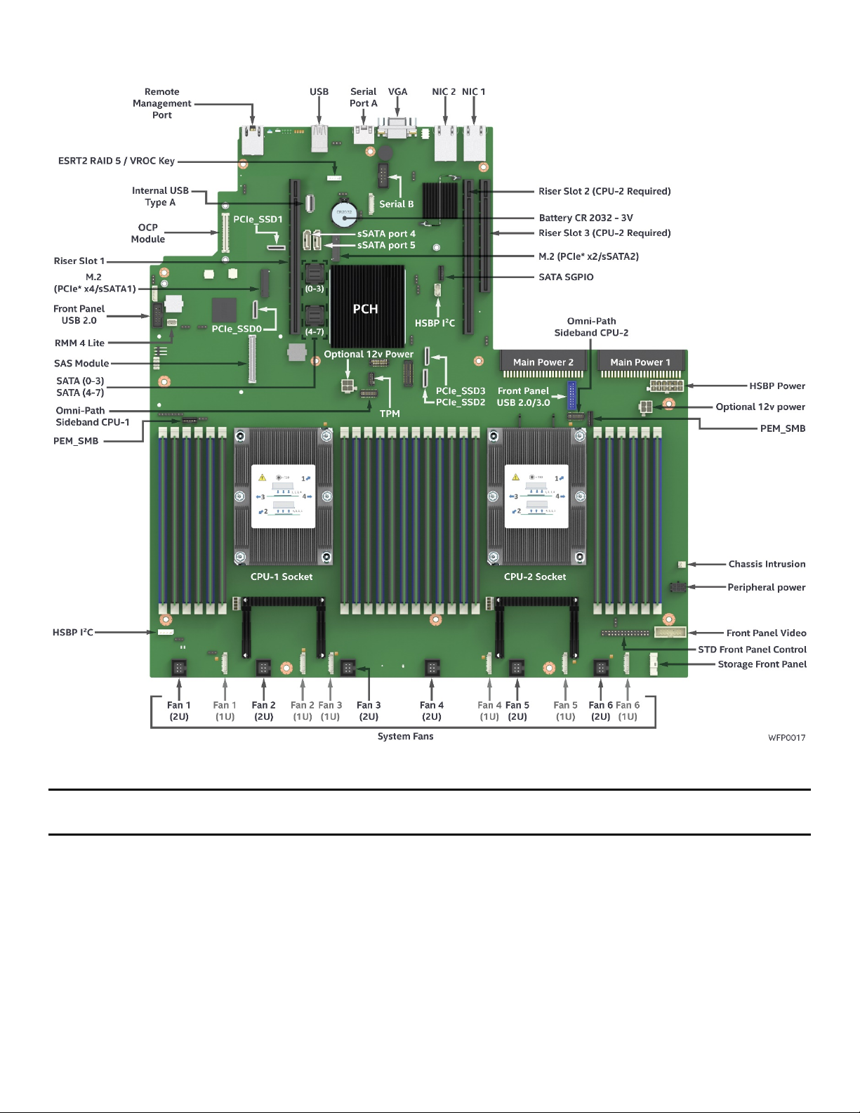
2.2 Server Board Component/Feature Identification
Figure 3. Server board component/feature identification
Note: Intel® Server Board S2600WFT shown. Some features may not be present on Intel® Server Boards
S2600WF0 and/or S2600WFQ.
19
Page 20
Intel® Server Board S2600WF Product Family Technical Product Specification
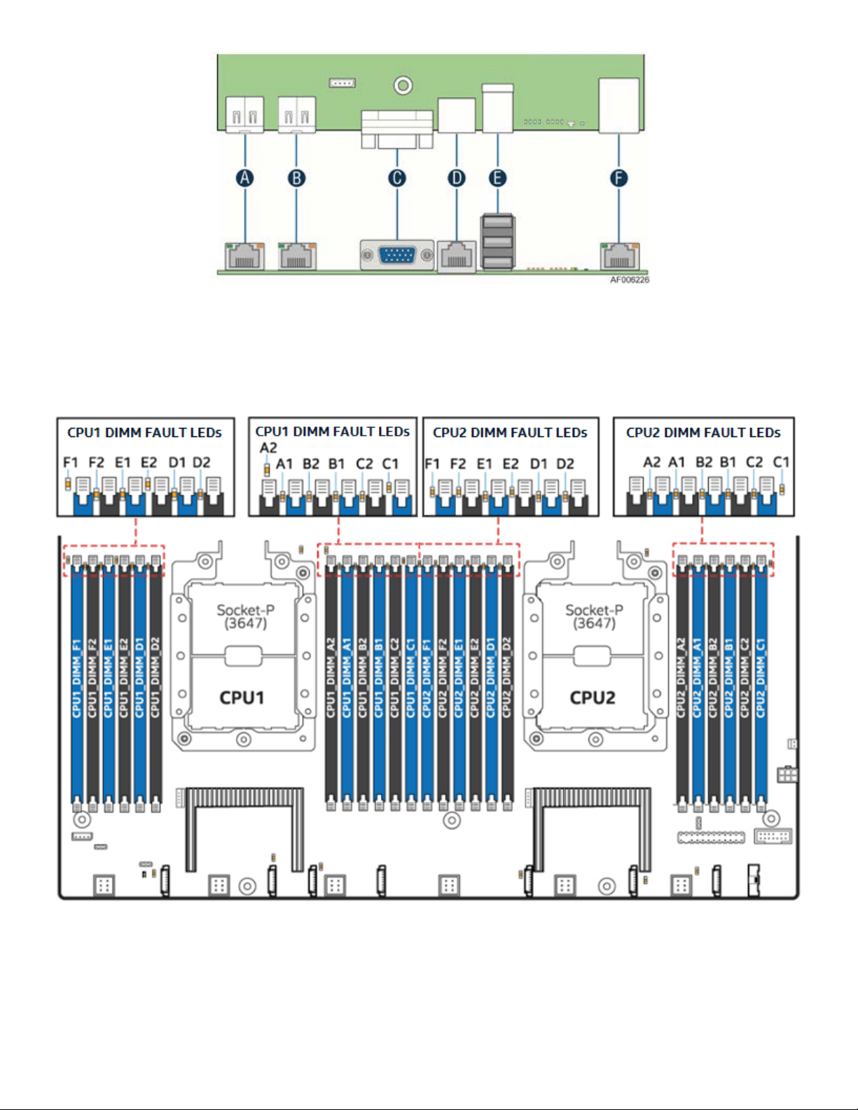
A – RJ45 network port – NIC #1
B – RJ45 network port – NIC #2
C – Video
D – RJ45 serial A port
E – Stacked 3-port USB 3.0
F – RJ45 dedicated management port
Figure 4. Intel® Server Board S2600WF external I/O connector layout
Figure 5. Intel® Light Guided Diagnostics - DIMM fault LEDs
20
Page 21
Intel® Server Board S2600WF Product Family Technical Product Specification
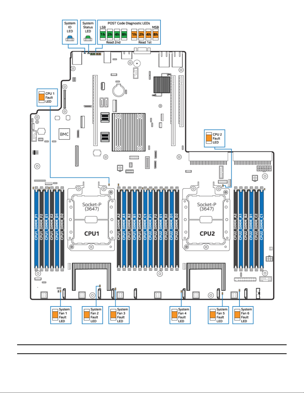
Figure 6. Intel® Light Guided Diagnostic – LED identification
Note: See Appendix B
for POST Code Diagnostic LED decoder information.
21
Page 22
Intel® Server Board S2600WF Product Family Technical Product Specification
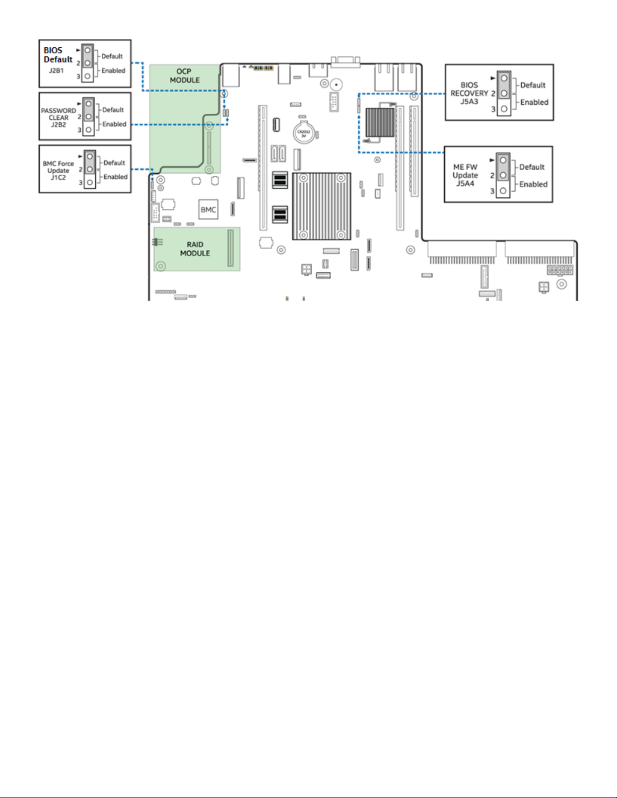
Figure 7. Board configuration and recovery jumpers
For more information on reset and recovery jumpers, see Section 11.
22
Page 23
Intel® Server Board S2600WF Product Family Technical Product Specification
2.3 Server Board Mechanical Drawings
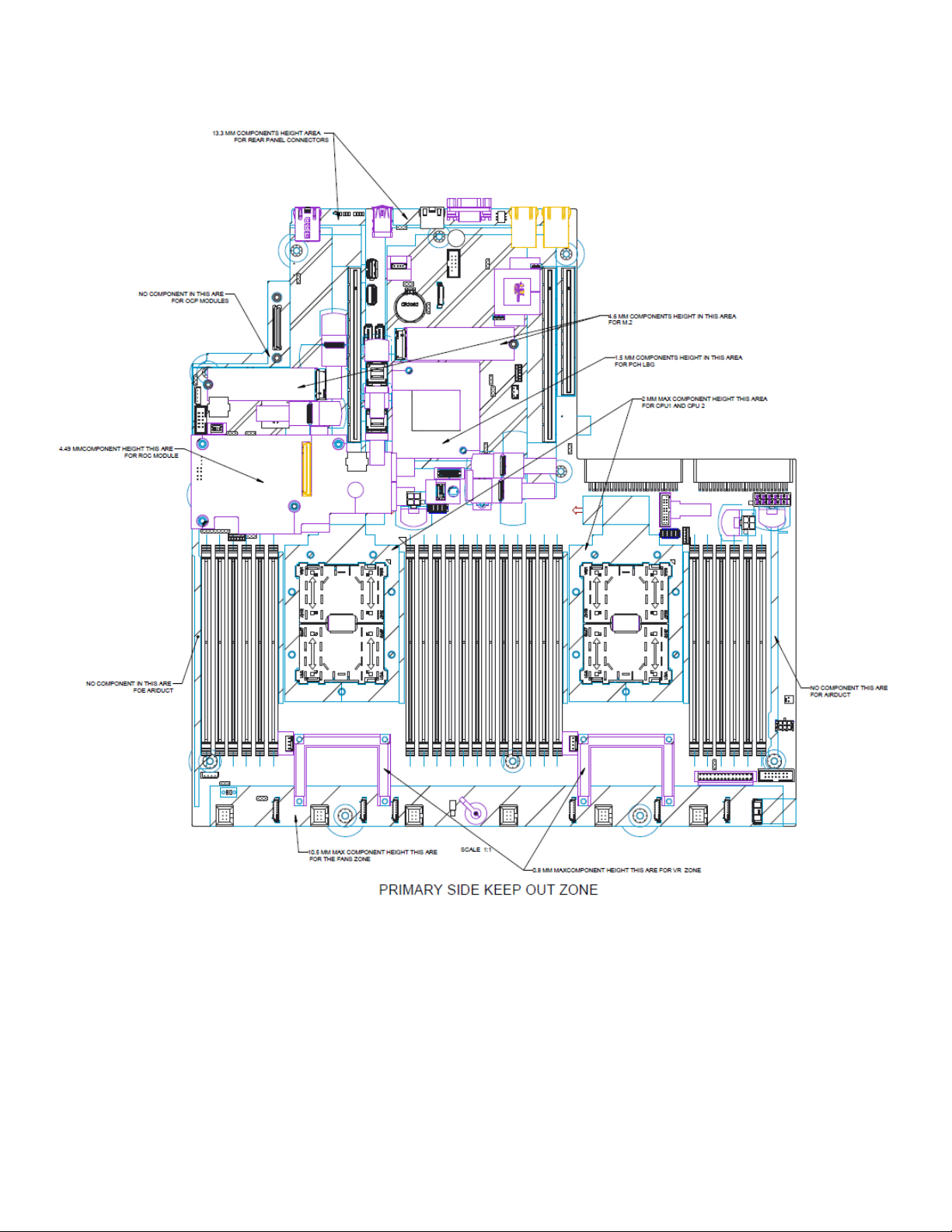
Figure 8. Intel® Server Board S2600WF primary side keepout zone
23
Page 24
Intel® Server Board S2600WF Product Family Technical Product Specification
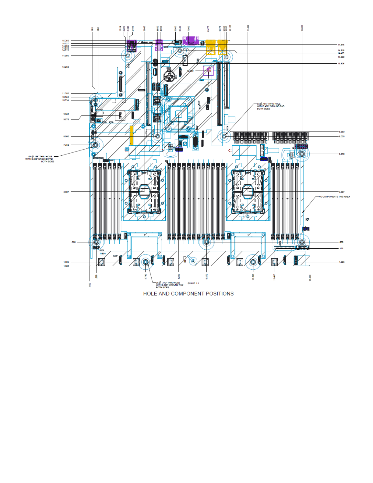
Figure 9. Intel® Server Board S2600WF hole and component positions
24
Page 25
Intel® Server Board S2600WF Product Family Technical Product Specification
Figure 10. Intel® Server Board S2600WF secondary side keepout zone
25
Page 26

Intel® Server Board S2600WF Product Family Technical Product Specification
Figure 11. Intel® Server Board S2600WF primary side height restrictions
26
Page 27
Intel® Server Board S2600WF Product Family Technical Product Specification
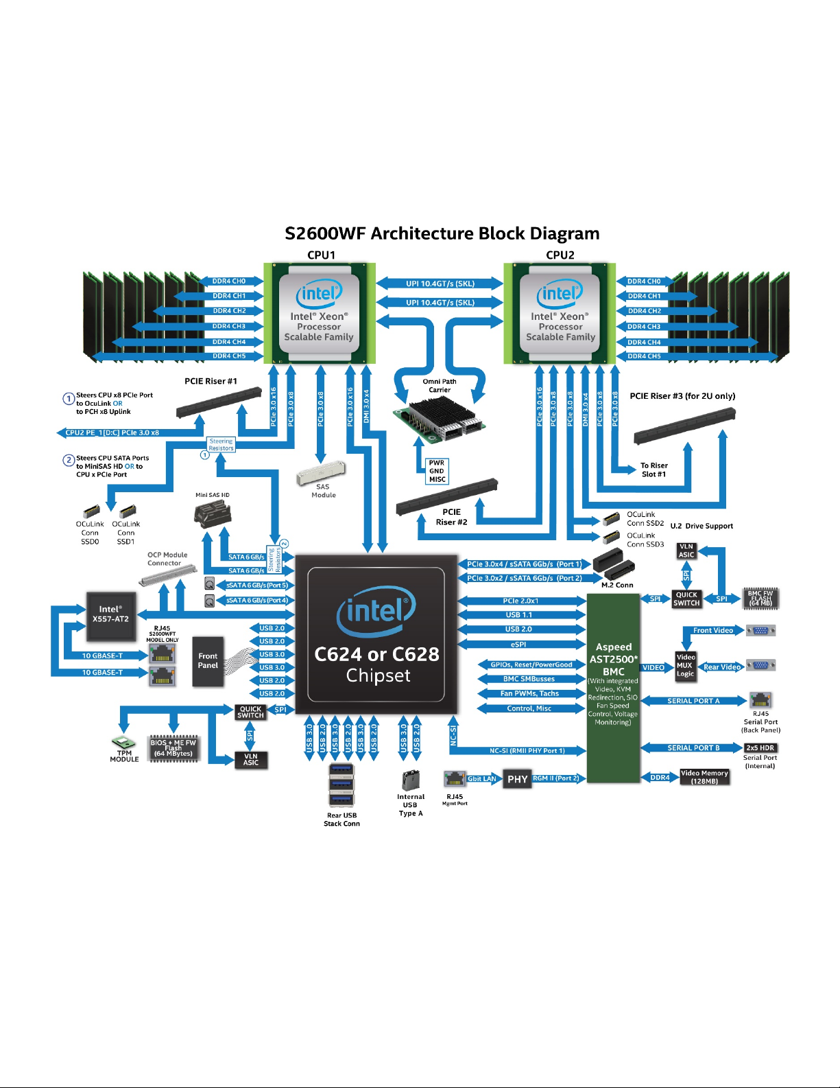
2.4 Product Architecture Overview
The architecture of Intel® Server Board S2600WF product family is developed around the integrated features
and functions of the Intel® Xeon® processor Scalable family, the Intel® C620 series chipset (PCH), Intel®
Ethernet Controller X557-AT2 (S2600WFT only), and the ASPEED* AST2500 baseboard management
controller (BMC).
Figure 12 provides an overview of the server board architecture, showing the features and interconnects of
each of the major sub-system components.
Figure 12. Intel® Server Board S2600WF product family architectural block diagram
27
Page 28
Intel® Server Board S2600WF Product Family Technical Product Specification
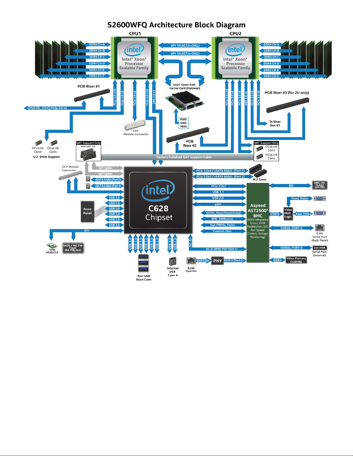
Figure 13. Intel® Server Board S2600WFQ architectural block diagram
2.5 System Software Stack
The server board includes a system software stack that consists of the bystem BIOS, BMC firmware, Intel®
Management Engine (Intel® ME) firmware, and field replacement unit (FRU) and sensor data record (SDR)
data. Together, they configure and manage features and functions of the server system.
Many features and functions of the server system are managed jointly by the system BIOS and the BMC
firmware, including:
• IPMI watchdog timer
• Messaging support, including command bridging and user/session support
• BIOS boot flags support
• Event receiver device – The BMC receives and processes events from the BIOS.
• Serial-over-LAN (SOL)
• ACPI state synchronization – The BMC tracks ACPI state changes that are provided by the BIOS.
28
Page 29

Intel® Server Board S2600WF Product Family Technical Product Specification
Hot Key
Function
<F2>
Enter the BIOS setup utility
<F6>
Pop-up BIOS boot menu
<F12>
Network boot
<Esc>
Switch from logo screen to diagnostic screen
<Pause>
Stop POST temporarily
• Fault resilient booting (FRB) – Fault resistant boot level 2 (FRB-2) is supported by the watchdog timer
functionality.
• Front panel management – The BMC controls the system status LED and chassis ID LED. It supports
secure lockout of certain front panel functionality and monitors button presses. The chassis ID LED is
turned on using a front panel button or a command.
• DIMM temperature monitoring – New sensors and improved acoustic management using closed-loop
fan control algorithm taking into account DIMM temperature readings.
• Integrated KVM
• Integrated remote media redirection
• Intel® Intelligent Power Node Manager support
• Sensor and SEL logging additions/enhancements (e.g., additional thermal monitoring capability)
• Embedded platform debug feature, which allows capture of detailed data for later analysis by Intel
A complete system software stack is pre-programmed on the server board during the board assembly
process, making the server board functional at first power on. However, to ensure the most reliable system
operation, it is highly recommended to check http://downloadcenter.intel.com
for the latest available system
updates.
System updates can be performed in a number of operating environments, including the UEFI shell using the
UEFI-only system update package (SUP), or under different operating systems using the Intel® One Boot
Flash Update (Intel® OFU) utility.
As part of the initial system integration process, system integrators must program system configuration data
onto the server board using the FRUSDR utility to ensure the embedded platform management subsystem is
able to provide the best performance and cooling for the final system configuration. The FRUSDR utility is
included in the SUP and OFU packages. For additional information, see Section 2.5.2.
Refer to the following Intel documents for more indepth information about the system software stack and
their functions:
• Intel® Server Board S2600 Family BIOS External Product Specification – Intel NDA Required
• Intel® Server System Integrated Baseboard Management Controller (BMC) Firmware External Product
Specification for Intel® Servers Systems supporting the Intel® Xeon® processor Scalable family – Intel
NDA Required
2.5.1 Hot Keys Supported During POST
Certain hot keys are recognized during power-on self-test (POST). A hot key is a key or key combination that
is recognized as an unprompted command input, where the operator is not prompted to press the hot key. In
most cases, hot keys are recognized even while other processing is in progress.
The BIOS supported hot keys are only recognized by the system BIOS during the system boot time POST
process. Once the POST process has completed and hands off the system boot process to the operating
system, BIOS supported hot keys are no longer recognized.
Table 3 provides a list of available POST hot keys along with a description for each.
29
Table 3. POST hot keys
Page 30

Intel® Server Board S2600WF Product Family Technical Product Specification
2.5.1.1 POST Logo/Diagnostic Screen
If quiet boot is enabled in the BIOS setup utility, a splash screen is displayed with the standard Intel logo
screen or a customized original equipment manufacturer (OEM) logo screen if one is present in the
designated flash memory location. By default, quiet boot is enabled in the BIOS setup utility and the logo
screen is the default POST display. However, the pressing <Esc> hides the logo screen and displays the
diagnostic screen instead.
If a logo is not present in the BIOS flash memory space, or if quiet boot is disabled in the system
configuration, the POST diagnostic screen is displayed with a summary of system configuration information.
The POST diagnostic screen is purely a text mode screen, as opposed to the graphics mode logo screen.
If console redirection is enabled in the BIOS setup utility, the quiet boot setting is disregarded and the text
mode diagnostic screen is displayed unconditionally. This is due to the limitations of console redirection,
which transfers data in a mode that is not graphics-compatible.
2.5.1.2 BIOS Boot Pop-Up Menu
The BIOS boot specification (BBS) provides a boot pop-up menu that can be invoked by pressing the <F6>
key during POST. The BBS pop-up menu displays all available boot devices. The boot order in the pop-up
menu is not the same as the boot order in the BIOS setup utility. The pop-up menu simply lists all of the
available devices from which the system can be booted, and allows a manual selection of the desired boot
device.
When an administrator password is installed in the BIOS setup utility, the administrator password is required
to access the boot pop-up menu. If a user password is entered, the user is taken directly to the boot manager
in the BIOS setup utility only allowing booting in the order previously defined by the administrator.
2.5.1.3 Entering BIOS Setup
To enter the BIOS setup utility using a keyboard (or emulated keyboard), press the <F2> function key during
boot time when the OEM or Intel logo screen or the POST diagnostic screen is displayed.
The following instructional message is displayed on the diagnostic screen or under the quiet boot logo
screen:
Press <F2> to enter setup, <F6> Boot Menu, <F12> Network Boot
Note: With a USB keyboard, it is important to wait until the BIOS discovers the keyboard and beeps; until the
USB controller has been initialized and the keyboard activated, key presses are not read by the system.
When the BIOS setup utility is entered, the main screen is displayed initially. However, if a serious error
occurs during POST, the system enters the BIOS setup utility and displays the error manager screen instead
of the main screen.
For additional BIOS setup utility information, refer to Intel® Server Board S2600 Family BIOS Setup User
Guide.
2.5.1.4 BIOS Update Capability
To bring BIOS fixes or new features into the system, it is necessary to replace the current installed BIOS
image with an updated one. The BIOS image can be updated using a standalone IFLASH32 utility in the UEFI
shell or using the OFU utility program under a supported operating system. Full BIOS update instructions are
provided with update packages downloaded from the Intel website.
30
Page 31

Intel® Server Board S2600WF Product Family Technical Product Specification
2.5.1.5 BIOS Recovery
If a system is unable to boot successfully to an OS, hangs during POST, or even hangs and fails to start
executing POST, it may be necessary to perform a BIOS recovery procedure to replace a defective copy of
the primary BIOS
The BIOS provides three mechanisms to start the BIOS recovery process, which is called recovery mode:
• The recovery mode jumper causes the BIOS to boot in recovery mode.
• At power on, if the BIOS boot block detects a partial BIOS update was performed, the BIOS
automatically boots in recovery mode.
• The BMC asserts the recovery mode general purpose input/output (GPIO) in case of partial BIOS
update and FRB-2 timeout.
The BIOS recovery takes place without any external media or mass storage device as it uses a backup BIOS
image inside the BIOS flash in recovery mode.
Note: The recovery procedure is included here for general reference. However, if in conflict, the instructions
in the BIOS release notes are the definitive version.
When the BIOS recovery jumper is set, the BIOS begins by logging a recovery start event to the system event
log (SEL). It then loads and boots with a backup BIOS image residing in the BIOS flash device. This process
takes place before any video or console is available. The system boots to the embedded UEFI shell, and a
recovery complete event is logged to the SEL. From the UEFI shell, the BIOS can then be updated using a
standard BIOS update procedure defined in update instructions provided with the system update package
downloaded from the Intel website. Once the update has completed, switch the recovery jumper back to its
default position and power cycle the system.
If the BIOS detects a partial BIOS update or the BMC asserts recovery mode GPIO, the BIOS boots in recovery
mode. The difference is that the BIOS boots up to the error manager page in the BIOS setup utility. In the
BIOS Setup utility, a boot device, shell or Linux*, for example, could be selected to perform the BIOS update
procedure under shell or OS environment.
Note: Before attempting a recovery boot, it is highly advisable to reference the BIOS Release Notes to verify
the proper recovery procedure.
2.5.2 Field Replaceable Unit (FRU) and Sensor Data Record (SDR) Data
As part of the initial system integration process, the server board/system must have the proper FRU and SDR
data loaded. This ensures that the embedded platform management system is able to monitor the
appropriate sensor data and operate the system with best cooling and performance. Once the system
integrator has performed an initial FRU SDR package update, subsequent auto-configuration occurs without
the need to perform additional SDR updates or provide other user input to the system when any of the
following components are added or removed:
• Processor
• Memory
• OCP module
• Integrated SAS RAID module
• Power supply
• Fan
• Intel® Xeon Phi™ co-processor PCIe* card
• Hot swap backplane
• Front panel
31
Page 32

Intel® Server Board S2600WF Product Family Technical Product Specification
Note: The system may not operate with best performance or best/appropriate cooling if the proper FRU and
SDR data is not installed.
2.5.2.1 Loading FRU and SDR Data
The FRU and SDR data can be updated using a standalone FRUSDR utility in the UEFI shell, or can be done
using the OFU utility program under a supported operating system. Full FRU and SDR update instructions are
provided with the appropriate system update package (SUP) or OFU utility which can be downloaded from
http://downloadcenter.intel.com
.
32
Page 33

Intel® Server Board S2600WF Product Family Technical Product Specification
3. Processor Support
The server board includes two Socket-P LGA3647 processor sockets compatible with the Intel® Xeon®
processor Scalable family (standard and fabric options) and supports processor thermal design power (TDP)
of up to 205 W.
Note: Previous-generation Intel® Xeon® processors and their supported CPU heat sinks are not compatible
on server boards described in this document.
Note: The server board is capable of supporting processors with a maximum 205 W TDP. However, TDP
support may vary depending on the cooling capabilities of the chosen server chassis. Check the server
chassis or server system product specifications to determine maximum supported processor TDP.
Visit http://www.intel.com/support for a complete list of supported processors.
3.1 Processor Socket and Processor Heat Sink Module (PHM) Assembly
This generation server board introduces the concept of the processor heat sink module (PHM). Figure 14
identifies each component associated with the processor assembly. The illustration does not represent the
processor installation process.
Figure 14. Processor heat sink module (PHM) components and processor socket reference diagram
Processor installation requires that the processor be attached to the processor heat sink prior to installation
onto the server board.as shown in Figure 15.
33
Page 34

Intel® Server Board S2600WF Product Family Technical Product Specification
Figure 15. Processor attached to the processor heat sink installation
Two bolster plate guide pins of different sizes allows the PHM to be installed only one way onto the
processor socket assembly (see Figure 14).
Figure 16. PHM to CPU socket orientation and alignment features
34
Page 35

Intel® Server Board S2600WF Product Family Technical Product Specification
The PHM is properly installed when it is securely seated over the two bolster plate guide pins and sits evenly
over the processor socket as shown in Figure 16. Once the PHM is properly seated over the processor socket
assembly, the four heat sink Torx* screws must be tightened in the order specified on the label affixed to the
top side of the processor heat sink.
Caution: Failure to tighten the heat sink screws in the specified order may cause damage to the processor
socket assembly. Heat sink screws should be tightened to 12 in-lbs torque.
Note: For detailed processor assembly and installation instructions, refer to the appropriate Intel product
family System Integration and Service Guide.
To protect the pins within a processor socket from being damaged, server boards with no processor or heat
sink installed must have a plastic cover installed over each processor socket, as shown in Figure 17.
Processor socket covers must be removed before processor installation (Figure 17 – B).
Figure 17. Processor socket assembly and protective cover
3.2 Processor Thermal Design Power (TDP) Support
To allow optimal operation and long-term reliability of Intel® processor-based systems, the processor must
remain within the defined minimum and maximum case temperature (T
not designed to provide sufficient thermal capability may affect the long-term reliability of the processor and
system. The server board described in this document is designed to support the Intel® Xeon® processor
Scalable family TDP guidelines up to and including 205 W.
Disclaimer Note: Intel® server boards contain a number of high-density VLSI and power delivery
components that need adequate airflow to cool. Intel ensures through its own chassis development and
testing that when Intel® server building blocks are used together, the fully integrated system meets the
intended thermal requirements of these components. It is the responsibility of the system integrator who
chooses not to use Intel-developed server building blocks to consult vendor datasheets and operating
parameters to determine the amount of airflow required for the specific application and environmental
conditions. Intel cannot be held responsible if components fail or the server board does not operate
correctly when used outside any of its published operating or non-operating limits.
CASE) specifications. Thermal solutions
35
Page 36

Intel® Server Board S2600WF Product Family Technical Product Specification
Feature
81xx
Platinum
61xx
Gold
51xx
Gold
41xx
Silver
31xx
Bronze
# of Intel® UPI Links
3 3 2
2
2
Intel UPI Speed
10.4 GT/s
10.4 GT/s
10.4 GT/s
9.6 GT/s
9.6 GT/s
2S-2UPI
8S- 3UPI
Node Controller Support
Yes
Yes
No
No
No
# of Memory Channels
6 6 6
6
6
Maximum DDR4 Speed
2666
2666
2400
2400
2133
768 GB
1.5 TB (select SKUs)
768 GB
1.5 TB (select SKUs)
768 GB
1.5 TB (select SKUs)
RAS Capability
Advanced
Advanced
Advanced
Standard
Standard
Intel® Turbo Boost Technology
Yes
Yes
Yes
Yes
No
Intel® HT Technology
Yes
Yes
Yes
Yes
No
Intel® AVX-512 ISA Support
Yes
Yes
Yes
Yes
Yes
Intel® AVX-512 - # of 512b FMA
Units
# of PCIe* Lanes
48
48
48
48
48
3.3 Intel® Xeon® Processor Scalable Family Overview
The Intel® Server Board S2600WF product family supports for the Intel® Xeon® processor Scalable family:
• Intel® Xeon® Bronze XXXX processor
• Intel® Xeon® Silver XXXX processor
• Intel® Xeon® Gold XXXX processor
• Intel® Xeon® Platinum XXXX processor
Table 4. Intel® Xeon® processor Scalable family feature comparison
2S-2UPI
2S-3UPI
4S-2UPI
4S-3UPI
2S-2UPI
4S-2UPI
2S-2UPI 2S-2UPI
768 GB 768 GB
Supported Topologies
Memory Capacity
2S-3UPI
4S-2UPI
4S-3UPI
2 2 1 1 1
The Intel® Xeon® processor Scalable family combines several key system components into a single processor
package, including the CPU cores, Integrated Memory Controller (IMC), and Integrated IO Module (IIO).
The processor core features and technologies include:
• Intel® Ultra Path Interconnect (Intel® UPI) – up to 10.4 GT/s
• Intel® Speed Shift Technology
• Intel® 64 Architecture
• Enhanced Intel SpeedStep® Technology
• Intel® Turbo Boost Technology 2.0
• Intel® Hyper-Threading Technology (Intel® HT Technology)
• Intel® Virtualization Technology (Intel® VT-x)
• Intel® Virtualization Technology for Directed I/O (Intel® VT-d)
• Execute Disable Bit
• Intel® Trusted Execution Technology (Intel® TXT)
• Intel® Advanced Vector Extensions (Intel® AVX-512)
• Intel® Advanced Encryption Standard New Instructions (Intel® AES-NI)
36
Page 37

Intel® Server Board S2600WF Product Family Technical Product Specification
The processor uncore featuresand technologies include:
• Up to 48 PCIe* lanes 3.0 lanes per CPU – 79GB/s bi-directional pipeline
• 6 channels DDR4 memory support per CPU
• On package integration of next generation Intel® Omni-Path Fabric Controller (select SKUs)
• DMI3/PCIe* 3.0 interface with a peak transfer rate of 8.0 GT/s
• Non-transparent bridge (NTB) enhancements – 3 full duplex NTBs and 32 MSI-X vectors
• Intel® Volume Management Device (Intel® VMD) – manages CPU attached NVMe* SSDs
• Intel® QuickData Technology
• Support for Intel® Node Manager 4.0
3.3.1 Supported Technologies
3.3.1.1 Intel® 64 Instruction Set Architecture
64-bit memory extensions to the IA-32 architecture. Further details on Intel 64 architecture and
programming model can be found at http://developer.intel.com/technology/intel64/
3.3.1.2 Intel® Hyper-Threading Technology (Intel® HT Technology)
The processor supports Intel® HT Technology, which allows an execution core to function as two logical
processors. While some execution resources such as caches, execution units, and buses are shared, each
logical processor has its own architectural state with its own set of general-purpose registers and control
registers. This feature must be enabled via the BIOS and requires operating system support.
.
3.3.1.3 Enhanced Intel SpeedStep® Technology
Processors in the Fifth Generation Intel® Core™ Processor Family support Enhanced Intel SpeedStep®
Technology. The processors support multiple performance states, which allows the system to dynamically
adjust processor voltage and core frequency as needed to enable decreased power consumption and
decreased heat production. All controls for transitioning between states are centralized within the processor,
allowing for an increased frequency of transitions for more effective operation.
The Enhanced Intel SpeedStep Technology feature may be enabled/disabled by an option on the Processor
Configuration Setup screen. By default Enhanced Intel SpeedStep Technology is enabled. If Enhanced Intel
SpeedStep Technology is disabled, then the processor speed is set to the processor’s maximum TDP core
frequency (nominal rated frequency).
3.3.1.4 Intel® Turbo Boost Technology 2.0
Turbo Boost Technology is featured on all processors in the Fifth Generation Intel® Core™ Processor
Intel®
Family. Intel
Turbo Boost Technology opportunistically and automatically allows the processor to run faster
than the marked frequency if the processor is operating below power, temperature, and current limits. This
results in increased performance for both multi-threaded and single-threaded workloads.
3.3.1.5 Intel® Virtualization Technology for IA-32, Intel® 64 and Intel® Architecture (Intel® VT-x)
Intel® Virtualization Technology for IA-32, Intel® 64 and Intel® Architecture (Intel® VT-x) provides hardware
support in the core to improve performance and robustness for virtualization. Intel VT-x specifications and
functional descriptions are included in the Intel 64 and IA-32 Architectures Software Developer’s Manual.
3.3.1.6 Intel® Virtualization Technology for Directed I/O (Intel® VT-d)
Intel® Virtualization Technology for Directed I/O (Intel® VT-d) provides hardware support in the core and
uncore implementations to improve I/O virtualization performance and robustness.
37
Page 38

Intel® Server Board S2600WF Product Family Technical Product Specification
3.3.1.7 Execute Disable Bit
Execute Disable Bit functionality can help prevent certain classes of malicious buffer overflow attacks when
combined with a supporting operating system. This allows the processor to classify areas in memory by
where application code can execute and where it cannot. When malicious code attempts to insert code in the
buffer, the processor disables code execution, preventing damage and further propagation.
3.3.1.8 Intel® Trusted Execution Technology for servers (Intel® TXT)
Intel® TXT defines platform-level enhancements that provide the building blocks for creating trusted
platforms. The Intel TXT platform helps to provide the authenticity of the controlling environment such that
those wishing to rely on the platform can make an appropriate trust decision. The Intel TXT platform
determines the identity of the controlling environment by accurately measuring and verifying the controlling
software.
3.3.1.9 Intel® Advanced Vector Extensions 512 (Intel AVX-512)
The base of the 512-bit single instruction multiple data (SIMD) instruction extensions are referred to as Intel®
AVX-512 foundation instructions. They include extensions of the Intel® Advanced Vector Extensions (Intel®
AVX) family of SIMD instructions but are encoded using a new scheme with support for 512-bit vector
registers, up to 32 vector registers in 64-bit mode, and conditional processing using opmask registers.
3.3.1.10 Intel® Advanced Encryption Standard New Instructions (Intel® AES-NI)
Intel® Advanced Encryption Standard New Instructions (Intel® AES-NI) is a set of instructions implemented in
all processors in the Fifth Generation Intel® Core™ Processor Family. This feature adds AES instructions to
accelerate encryption and decryption operations used in the Advanced Encryption Standard. The Intel
NI feature includes six additional SIMD instructions in the Intel®
Streaming SIMD Extensions (Intel® SSE)
AES-
instruction set.
The BIOS is responsible in POST to detect whether the processor has the Intel AES-NI instructions available.
Some processors may be manufactured without Intel AES-NI instructions.
The Intel AES-NI instructions may be enabled or disabled by the BIOS. Intel AES-NI instructions are enabled
unless the BIOS has explicitly disabled them.
3.3.1.11 Intel® Intelligent Power Node Manager 4.0
The Intel® ME on the Intel® C620 series chipset supports Intel® Intelligent Power Node Manager technology.
The Intel ME/Intel® Node Manager (Intel® NM) combination is a power and thermal control capability on the
platform, which exposes external interfaces that allow IT (through external management software) to query
the Intel ME about platform power capability and consumption, thermal characteristics, and specify policy
directives (that is, set a platform power budget). Intel ME enforces these policy directives by controlling the
power consumption of underlying subsystems using available control mechanisms (such as processor P/T
states). The determination of the policy directive is done outside of Intel ME either by intelligent
management software or by the IT operator.
Below are the some of the applications of Intel Intelligent Power Node Manager technology:
• Platform power monitoring and limiting – The Intel ME/Intel NM monitors platform power
consumption and holds average power over duration. It can be queried to return actual power at any
given instance. The power limiting capability is to allow external management software to address
key IT issues by setting a power budget for each server.
• Inlet air temperature monitoring – The Intel ME/Intel NM monitors server inlet air temperatures
periodically. If there is an alert threshold in effect, then Intel ME/Intel NM issues an alert when the
inlet (room) temperature exceeds the specified value. The threshold value can be set by policy.
38
Page 39

Intel® Server Board S2600WF Product Family Technical Product Specification
Feature
81XXF
Platinum
61XXF
Gold
# of Cores
≥ 24
< 24
# of Intel® OP HFI Ports
1
1
# of Intel® UPI Links 2 2
Intel® UPI Speed
10.4 GT/s
10.4 GT/s
Supported Topologies
2S-2UPI
2S-2UPI
Node Controller Support
No
No
# of Memory Channels 6 6
Max DDR4 Speed
2666
2666
768 GB
1.5 TB (select SKUs)
768 GB
1.5 TB (select SKUs)
RAS Capability
Standard
Standard
Intel® Turbo Boost
Yes
Yes
Intel® HT Technology
Yes
Yes
Intel® AVX-512 ISA Support
Yes
Yes
Intel® AVX-512 - # of 512b FMA Units
2
2
# of PCIe* Lanes
48
48
• Memory subsystem power limiting – The Intel ME/Intel NM monitors memory power consumption.
Memory power consumption is estimated using average bandwidth utilization information.
• Processor power monitoring and limiting – The Intel ME/Intel NM monitors processor or socket
power consumption and holds average power over duration. It can be queried to return actual power
at any given instant. The monitoring process of the Intel ME is used to limit the processor power
consumption through processor P-states and dynamic core allocation.
• Core allocation at boot time – Restrict the number of cores for OS/VMM use by limiting how many
cores are active at boot time. After the cores are turned off, the CPU limits how many working cores
are visible to the BIOS and OS/VMM. The cores that are turned off cannot be turned on dynamically
after the OS has started. It can be changed only at the next system reboot.
• Core allocation at run-time – This particular use case provides a higher level processor power
control mechanism to a user at runtime, after booting. An external agent can dynamically use or not
use cores in the processor subsystem by requesting Intel ME/Intel NM to control them, specifying the
number of cores to use or not use.
For additional information, visit
http://www.intel.com/content/www/us/en/data-center/data-center-
management/node-manager-general.html.
3.3.2 Intel® Xeon® Processor Scalable Family with Integrated Intel® Omni-Path Fabric
The Intel® Xeon® processor Scalable family includes SKUs which include an integrated Intel® Omni-Path Host
Fabric Interface (Intel® OP HFI) connector.
Table 5. Intel® Xeon® processor Scalable family with integrated Intel® OP HFI features
Memory Capacity
The current fabric port count is one port per processor socket. Each Intel OP HFI port supports four lanes of
25 Gbps, providing 100 Gbps of bandwidth in a single direction.
39
Page 40

Intel® Server Board S2600WF Product Family Technical Product Specification
1 port x 100 Gbps
Intel® OP HFI Connector
Figure 18. Intel® OP HFI connector location
Fabric processor support is a multi-chip package (MCP) option, where the processor Intel OP HFI connector
is cabled to an IFT carrier board installed into in any available PCIe* add-in card slot or within the OCP
module bay. A second cable carrying Intel Omni-Path side band signals is connected between the IFT carrier
board and sideband connectors on the server board. External cables attach the IFT carrier board to an
external Intel Omni-Path Switch.
Figure 19. Multi-chip package (MCP)
The following figure illustrates two supported dual processor configurations with one or two fabric
processors. In the diagram, each processor HFI connector is cabled to a QSFP28 interface card
40
Page 41

Intel® Server Board S2600WF Product Family Technical Product Specification
Intel Product Code (iPC)
Description
Accessory Kit Contents
1 – Dual port IFT Carrier Mezzanine Card
1 – Dual Port IFT Carrier PCIe Add-in Card
2 – Fabric Processor Carriers
Intel® Server S2600WF
Intel® Xeon®
processor Scalable
family
Internal Intel® OP HFI cable
to QSFP Interface card
Intel® Xeon® processor
Scalable family with
Integrated Intel® OP HFI
Intel® OP HFI QSFP
Interface card
Intel® Omni-Path Fabric Switch
Figure 20. Dual processor configurations with one or two fabric processors
3.3.3 Intel®Omni-Path IFT Carrier Accessory Kits
Intel® Server S2600WF
Dual Intel® Xeon® processor
Scalable family with
Integrated Intel® OP HFI
All necessary components to support up to two fabric processors are included in orderable accessory kits
(AWF1PFABKITM and AWF1PFABKITP).
1 – Internal Omni-Path Cable (CPU1)
AWF1PFABKITM Intel IFT Carrier Kit – Mezzanine
AWF1PFABKITP Intel IFT Carrier Kit – PCIe*
1 – Internal Omni-Path Cable (CPU2)
1 – Internal Omni-Path Sideband Cable
2 – Fabric Processor Carriers
1 – Internal Omni-Path Cable (CPU1)
1 – Internal Omni-Path Cable (CPU2)
1 – Internal Omni-Path Sideband Cable
Two options for the IFT carrier card are offered:
• Mezannine – Mounted directly to the server board in the designated OCP module mounting location.
• PCIe add-in card – Installed to any available riser slot 2 PCIe add-in slot.
41
Page 42

Intel® Server Board S2600WF Product Family Technical Product Specification
Mezzanine IFT Carrier Card
External QSFP28
PCIe* IFT Carrier Card
Connectors
Internal Omni-Path Sideband
Internal Omni-Path IFT Card-to-CPU
Fabric Procsessor Carrier x2
Figure 21. Intel® Omni-Path IFT Carrier Accessory Kit components
The sideband cable connects the IFT carrier board to each fabric processor sideband connector on the
server board. The sideband connectors are shown in Figure 22.
Fabic Sideband
CPU2
Fabic Sideband
CPU1
Figure 22. Server board sideband connectors
Each IFT carrier port has one green status LED as shown in Figure 23
42
Page 43

Intel® Server Board S2600WF Product Family Technical Product Specification
LED State
Description
Off
No link
Blinking slowly
Link established but not activated by management
Solid on
Link activated by management; but no traffic is present
Steady blinking
Traffic is present
Figure 23. IFT carrier board – rear view
Table 6. IFT carrier LED functionality
For external connection, the IFT carrier includes two QSFP+28 style connectors. The signal definition of
these connectors consists of the high speed diff pairs, miscellaneous sideband signals, and 3.3 V power. The
3.3 V power is used for the active logic within the QSFP+ modules. As noted in Table 7, QSFP+ modules have
four power classes that control how much power the active logic in the cable can consume.
Table 7. Power level classification for QSFP+ modules
Power Level Class Max Power (W)
1 1.5
2 2.0
3 2.5
4 3.5
The server board has support for processor configurations where one or two installed processors may have
an Intel OP HFI. In dual processor configurations, with at least one processor having support for Intel OP HFI,
the following population rules apply:
• The base SKU number of both processor types must be the same.
o Example: Intel® Xeon® Platinum 8160F (Intel OP HFI) + Intel Xeon Platinum 8160 (non-fabric)
o Example: Intel Xeon Gold 6140F (Intel OP HFI) + Intel Xeon Gold 6140F (Intel OP HFI)
There is no restriction on which processor socket is populated with the fabric processor and which processor
socket is populated with the matching non-fabric processor.
Table 8. Supported processor mixing – fabric vs non-fabric processors
CPU Socket 1 CPU Socket 2 Platform Expected Behavior
Processor Processor Boot to OS
Processor Fabric Processor Boot to OS
Fabric Processor Processor Boot to OS
Fabric Processor Fabric Processor Boot to OS
43
Page 44

Intel® Server Board S2600WF Product Family Technical Product Specification
3.4 Processor Population Rules
Note: The server board may support dual-processor configurations consisting of different processors that
meet the defined criteria below; however, Intel does not perform validation testing of this configuration. In
addition, Intel does not guarantee that a server system configured with unmatched processors will operate
reliably. The system BIOS does attempt to operate with processors which are not matched but are generally
compatible. For optimal system performance in dual-processor configurations, Intel recommends that
identical processors be installed.
When using a single processor configuration, the processor must be installed into the processor socket
labeled “CPU_1”.
Note: Some server board features may not be functional unless a second processor is installed (see
12).
When two processors are installed, the following population rules apply:
• Both processors must have the same number of cores.
• Both processors must have the same cache sizes for all levels of processor cache memory.
• Both processors must support identical DDR4 memory frequencies.
• Both processors must have identical extended family, extended model, processor type, family code
and model number.
• Processors with FPGA and processors with Intel® Omni-Path Fabric cannot be mixed.
Processors with different core frequencies can be mixed in a system, given that the prior rules are met. If this
condition is detected, all processor core frequencies are set to the lowest common denominator (highest
common speed) and an error is reported.
Processor stepping within a common processor family can be mixed as long as it is listed in the processor
specification updates published by Intel. Mixing of steppings is only validated and supported between
processors that are plus or minus one stepping from each other.
Figure
3.5 Processor Initialization Error Summary
Table 9 describes mixed processor conditions and recommended actions for all Intel® server boards and
Intel server systems designed around the Intel® Xeon® processor E5-2600 v5 product family and Intel® C620
chipset architecture. The errors fall into one of the following categories:
• Fatal: If the system cannot boot, POST halts and display the following message:
Unrecoverable fatal error found. System will not boot until the error is
resolved
Press <F2> to enter setup
When the <F2> key on the keyboard is pressed, the error message is displayed on the error manager
screen and an error is logged to the system event log (SEL) with the POST error code.
The “POST Error Pause” option setting in the BIOS setup does not have any effect on this error.
If the system is not able to boot, the system generates a beep code consisting of three long beeps
and one short beep. The system cannot boot unless the error is resolved. The faulty component must
be replaced.
44
Page 45

Intel® Server Board S2600WF Product Family Technical Product Specification
Error
Severity
System Action when BIOS Detects the Error Condition
• Halts at POST code 0xE6.
Takes fatal error action (see above) and does not boot until the fault condition is remedied.
• Logs the POST error code into the SEL.
• Takes fatal error action (see above) and does not boot until the fault condition is remedied.
Processor
identical
• Halts at POST code 0xE5.
Takes fatal error action (see above) and does not boot until the fault condition is remedied.
Processor cache or
identical
• Halts at POST code 0xE5.
• Takes fatal error action (see above) and does not boot until the fault condition is remedied.
If the frequencies for all processors can be adjusted to be the same:
• Takes fatal error action (see above) and does not boot until the fault condition is remedied
If the link frequencies for all Intel® Ultra Path Interconnect (Intel® UPI) links can be adjusted to be
Takes fatal error action (see above) and does not boot until the fault condition is remedied.
The system status LED is set to a steady amber color for all fatal errors that are detected during
processor initialization. A steady amber system status LED indicates that an unrecoverable system
failure condition has occurred.
• Major: An error message is displayed to the error manager screen and an error is logged to the SEL. If
the BIOS setup option “Post Error Pause” is enabled, operator intervention is required to continue
booting the system. If the BIOS setup option “POST Error Pause” is disabled, the system continues to
boot.
• Minor: An error message may be displayed to the screen or to the BIOS setup error manager and the
POST error code is logged to the SEL. The system continues booting in a degraded state. The user
may want to replace the erroneous unit. The “POST Error Pause” option setting in the BIOS setup
does not have any effect on this error.
Table 9. Mixed processor configurations error summary
Processor family
not identical
Processor model
not identical
cores/threads not
home agent not
Processor
frequency (speed)
not identical
Fatal
Fatal
Fatal
Fatal
Fatal
• Halts with three long beeps and one short beep.
•
• Alerts the BMC to set the system status LED to steady amber.
• Displays 0196: Processor model mismatch detected message in the error manager.
• Halts with three long beeps and one short beep.
•
• Halts with three long beeps and one short beep.
• Adjusts all processor frequencies to the highest common frequency.
• Does not generate an error – this is not an error condition.
• Continues to boot the system successfully.
If the frequencies for all processors cannot be adjusted to be the same:
• Logs the POST error code into the SEL.
• Alerts the BMC to set the system status LED to steady amber.
• Does not disable the processor.
• Displays 0197: Processor speeds unable to synchronize message in the error
manager.
the same:
• Adjusts all Intel UPI interconnect link frequencies to highest common frequency.
• Does not generate an error – this is not an error condition.
Processor
Intel® UPI link
frequencies not
identical
45
Fatal
• Continues to boot the system successfully.
If the link frequencies for all Intel UPI links cannot be adjusted to be the same:
• Logs the POST error code into the SEL.
• Alerts the BMC to set the system status LED to steady amber.
• Does not disable the processor.
• Displays 0195: Processor Intel(R) UPI link frequencies unable to
synchronize message in the error manager.
•
Page 46

Intel® Server Board S2600WF Product Family Technical Product Specification
Error
Severity
System Action when BIOS Detects the Error Condition
• Logs the POST error code into the SEL.
manager waiting for operator intervention.
• Logs the POST error code into the SEL.
ting in setup.
Processor
microcode update
failed
Processor
microcode update
missing
Major
Minor
• Displays 816x: Processor 0x unable to apply microcode update message in the
error manager or on the screen.
• Takes major error action. The system may continue to boot in a degraded state, depending on
the “POST Error Pause” setting in setup, or may halt with the POST error code in the error
• Displays 818x: Processor 0x microcode update not found message in the error
manager or on the screen.
• The system continues to boot in a degraded state, regardless of the “POST Error Pause” set-
46
Page 47

Intel® Server Board S2600WF Product Family Technical Product Specification
4. System Memory
This chapter describes the architecture that drives the memory sub-system, supported memory types,
memory population rules, and supported memory reliability, accessibility, and serviceability (RAS) features.
4.1 Memory Subsystem Architecture
Figure 24. Memory subsystem architecture
Note: This generation server board supports DDR4 memory only.
The Intel® Server Board S2600WF supports up to 24 DDR4 DIMMs, 12 per processor. Each installed
processor supports six memory channels via two integrated memory controllers (IMC). On the server board,
memory channels are assigned an identifier letter A through F, with each memory channel supporting two
DIMM slots.
The server board supports the following:
• DDR4 DIMMs only.
• Registered DIMMs (RDIMMs), Load Reduced DIMMs (LRDIMMs), and NVDIMMs (Non-Volatile Dual
Inline Memory Module).
• Only Error Correction Code (ECC) enabled RDIMMs or LRDIMMs.
• Only RDIMMs and LRDIMMs with integrated Thermal Sensor On Die (TSOD).
• DIMM sizes of 4 GB, 8 GB, 16 GB, 32 GB, 64 GB and 128 GB depending on ranks and technology.
• Maximum DIMM speeds dependent on the processor SKU installed in the system:
o Intel® Xeon® Platinum 81xx processor – Max. 2666 Mega Transfers/second (MT/s)
o Intel® Xeon® Gold 61xx processor – Max. 2666 MT/s
o Intel® Xeon® Gold 51xx processor – Max. 2400 MT/s
o Intel® Xeon® Silver processor – Max. 2400 MT/s
o Intel® Xeon® Bronze processor – Max. 2133 MT/s
• DIMMs organized as Single Rank (SR), Dual Rank (DR), or Quad Rank (QR)
o RDIMMS – Registered DIMMS – SR/DR/QR, ECC only
o LRDIMMs – Load Reduced DIMMs – QR only, ECC only
o Maximum of 8 logical ranks per channel
o Maximum of 10 physical ranks loaded on a channel
47
Page 48

Intel® Server Board S2600WF Product Family Technical Product Specification
4.2 Supported Memory
Table 10.DDR4 RDIMM and LRDIMM support
4.3 Memory Slot Identification and Population Rules
Note: Although mixed DIMM configurations may be functional, Intel only supports and performs platform
validation on systems that are configured with identical DIMMs installed.
On the Intel® Server Board S2600WF, a total of 24 DIMM slots are provided – 2 CPUs, 6 Memory
Channels/CPU, 2 DIMMs/Channel. Figure 25 identifies all DIMM slots on the server board.
Figure 25. Intel® Server Board S2600WF memory slot layout
The following memory population rules apply when installing DIMMs:
48
Page 49

Intel® Server Board S2600WF Product Family Technical Product Specification
• Each installed processor provides six channels of memory. Memory channels from each processor are
identified as Channels A – F.
• Each memory channel supports two DIMM slots, identified as slots 1 and 2.
o On the server board, each DIMM slot is labeled by CPU #, memory channel, and slot # such as
CPU1_DIMM_A2 and CPU2_DIMM_A2.
• DIMM population rules require that DIMMs within a channel be populated starting with the blue DIMM
slot or DIMM farthest from the processor in a “fill-farthest” approach.
• When only one DIMM is used for a given memory channel, it must be populated in the blue DIMM slot
(furthest from the CPU).
• Mixing of DDR4 DIMM types (RDIMM, LRDIMM, 3DS RDIMM, 3DS LRDIMM, NVDIMM) within a channel
socket or across sockets produces a Fatal Error Halt during memory initialization.
• Mixing DIMMs of different frequencies and latencies is not supported within or across processor
sockets. If a mixed configuration is encountered, the BIOS attempts to operate at the highest
common frequency and the lowest latency possible.
• When populating a quad-rank DIMM with a single- or dual-rank DIMM in the same channel, the quad-
rank DIMM must be populated farthest from the processor. Incorrect DIMM placement results in an
MRC error code. A maximum of 8 logical ranks can be used on any one channel, as well as a maximum
of 10 physical ranks loaded on a channel.
• To install three quad-rank LRDIMMs on the same channel, they must be operated with rank
multiplication as RM = 2. This makes each LRDIMM appear as a dual-rank DIMM with ranks twice as
large.
• The memory slots associated with a given processor are unavailable if the corresponding processor
socket is not populated.
• A processor may be installed without populating the associated memory slots, provided a second
processor is installed with associated memory.
In this case, the memory is shared by the processors.
However, the platform suffers performance degradation and latency due to the remote memory.
• Processor sockets are self-contained and autonomous. However, all memory subsystem support
(such as memory RAS and error management) in the BIOS setup are applied commonly across
processor sockets.
• For multiple DIMMs per channel:
o For RDIMM, LRDIMM, 3DS RDIMM, 3DS LRDIMM; always populate DIMMs with higher electrical
loading in slot1, followed by slot 2.
49
Page 50

Intel® Server Board S2600WF Product Family Technical Product Specification
4.3.1 DIMM Population Guidelines for Best Performance
Processors within the Intel Xeon processor Scalable family include two integrated memory controllers (IMC),
each supporting three memory channels.
Figure 26. DIMM population diagram
For best performance, each processor should have matching DIMM configurations and DIMMs should be
populated using the following guidelines:
• 1 DIMM to 3 DIMM configurations – DIMMs should be populated to DIMM slot 1 (blue slots) of
channels A thru C.
• 4 DIMM configurations – DIMMs should be populated to DIMM slot 1 (blue slots) of channels A, B, D,
and E.
• 5 DIMM configurations – Not recommended. This is an unbalanced configuration that yields less than
optimal performance.
• 6 DIMM configurations – DIMMs should be populated to DIMM slot1 (blue slots) of all channels.
• 7 DIMM configurations – Not recommended. This is an unbalanced configuration that yields less than
optimal performance.
• 8 DIMM configurations – DIMMs should be populated to DIMM slots 1 and 2 of channels A, B, D, and
E.
• 9 DIMM, 10, DIMM, and 11 DIMM configurations – Not recommended. These are an unbalanced
configurations that yield less than optimal performance.
• 12 DIMM configurations – DIMMs are populated to all DIMM slots.
50
Page 51

Intel® Server Board S2600WF Product Family Technical Product Specification
RAS Feature
Description
Standard
Advanced
Device Data Correction
x8 Single Device Data Correction (SDDC) via static virtual lockstep
Adaptive Data Correction (SR) (Applicable to x4 DRAM DIMMs)
√
√
x8 Single Device Data Correction + 1 bit (SDDC+1) (Applicable to x8
SDDDC + 1, and ADDDC (MR) + 1 (Applicable to x4 DRAM DIMMs)
√
DDR4 Command/Address
DDR4 Command/Address Parity Check and Retry:
CMD/ADDR Retry
DDR4 Write Data CRC
DDR4 Write Data CRC Protection detects DDR4 data bus faults during
Memory Demand and Patrol
Demand scrubbing is the ability to write corrected data back to the
Memory Mirroring
Full Memory Mirroring: An intra IMC method of keeping a duplicate
Address Range/Partial Memory Mirroring: Provides further intra socket
Sparing
Dynamic fail-over of failing Ranks to spare Ranks behind the same
With Multi Rank up to two ranks out of a maximum of eight ranks can be
iMC’s Corrupt Data
Corrupt Data Containment is a process of signaling error along with the
Failed DIMM Isolation
Ability to identify a specific failing DIMM thereby enabling the user to
Memory Disable and Map Out
Allows memory initialization and booting to OS even when memory
Post Package Repair
Starting with DDR4 technology there is an additional capability
4.4 Memory RAS Features
Supported memory RAS features are dependent on the level of processor installed. Each processor level
within the Intel Xeon processor Scalable family has support for either standard or advanced memory RAS
features as defined in Table 11.
Table 11. Memory RAS features
Parity Check and Retry
Protection
Scrubbing
(Applicable to x8 DRAM DIMMs)
DRAM DIMMs)
Is a DDR4 technology based CMD/ADDR parity check and retry with
following attributes:
• CMD/ADDR Parity error “address“ logging
•
write operation.
memory once a correctable error is detected on a read transaction.
Patrol scrubbing proactively searches the system memory, repairing
correctable errors. Prevents accumulation of singlebit errors.
(secondary or mirrored) copy of the contents of memory as a redundant
backup for use if the primary memory fails. The mirrored copy of the
memory is stored in memory of the same processor socket's IMC.
Dynamic (without reboot) failover to the mirrored DIMMs is transparent
to the OS and applications.
√ √
√
√ √
√ √
√ √
√ √
granularity to mirroring of memory by allowing the firmware or OS to
determine a range of memory addresses to be mirrored, leaving the rest
of the memory in the socket in non-mirror mode.
• Rank Level Memory Sparing
• Multi-rank Level Memory
Sparing
Containment
for FRB
Note: RAS features may not be supported on all SKUs of a processor type.
51
memory controller DDR ranks.
assigned as spare ranks.
detected UC data. iMC's patrol scrubber and sparing engine have the
ability to poison the UC data.
replace only the failed DIMM(s). In case of uncorrected error and
lockstep mode, only DIMM-pair level isolation granularity is supported.
fault occurs.
available known as PPR (Post Package Repair). PPR offers additional
spare capacity within the DDR4 DRAM that can be used to replace faulty
cell areas detected during system boot time.
√
√ √
√ √
√ √
√ √
√ √
√ √
Page 52

Intel® Server Board S2600WF Product Family Technical Product Specification
4.4.1 DIMM Populations Rules and BIOS Setup for Memory RAS
• Memory sparing and memory mirroring options are enabled in BIOS setup.
• Memory sparing and memory mirroring options are mutually exclusive. Only one operating mode
may be selected in BIOS setup.
• If a RAS mode has been enabled, and the memory configuration is not able to support it during boot,
the system will fall back to independent channel mode and log and display errors.
• Rank sparing mode is only possible when all channels that are populated with memory that meet the
reaquirement of having at least two single-rank or double-rank DIMMs installed, or at least one quadrank DIMM installed, on each populated channel.
• Memory mirroring mode requires that for any channel pair that is populated with memory, the
memory population on both channels of the pair must be identically sized.
52
Page 53

Intel® Server Board S2600WF Product Family Technical Product Specification
CPU 1
CPU 2
Port DMI 3 - x4
Chipset
Port DMI 3 - x4
Riser Slot #3
Port 1A - x4
Riser Slot #1
Port 1A - x4
Riser Slot #2
Port 1B - x4
Riser Slot #1
Port 1B - x4
Riser Slot #2
Port 1C – x4
Riser Slot #1
Port 1C – x4
Riser Slot #1
Port 1D – x4
Riser Slot #1
Port 1D – x4
Riser Slot #1
Port 2A - x4
Chipset (PCH) - uplink
Port 2A - x4
Riser Slot #2
Port 2B - x4
Chipset (PCH) - uplink
Port 2B - x4
Riser Slot #2
Port 2C - x4
Chipset (PCH) - uplink
Port 2C - x4
Riser Slot #2
Port 2D - x4
Chipset (PCH) - uplink
Port 2D - x4
Riser Slot #2
Port 3A - x4
SAS Module
Port 3A - x4
OCuLink PCIe_SSD2
Port 3B - x4
SAS Module
Port 3B - x4
OCulink PCIe_SSD3
Port 3C - x4
OCuLink PCIe_SSD0
Port 3C - x4
Riser Slot #3
Port 3D -x4
OCuLInk PCIe_SSD1
Port 3D -x4
Riser Slot #3
5. PCIe* Support
The PCI Express* (PCIe*) interface of the Intel® Server Board S2600WF product family is fully compliant with
the PCIe Base Specification, Revision 3.0 supporting the following PCIe bit rates: Gen 3.0 (8.0 GT/s), Gen 2.0
(5.0 GT/s), and Gen 1.0 (2.5 GT/s).
For specific board features and functions supported by the PCIe sub-system, see Chapter 6. Table 12
provides the PCIe port routing information from each processor:
Table 12. CPU - PCIe* port routing
PCI Ports Onboard Device PCI Ports Onboard Device
5.1.1 PCIe* Enumeration and Allocation
The BIOS assigns PCI bus numbers in a depth-first hierarchy, in accordance with the PCI Local Bus
Specification, Revision 3.0. The bus number is incremented when the BIOS encounters a PCI-PCI bridge
device.
Scanning continues on the secondary side of the bridge until all subordinate buses are assigned numbers.
PCI bus number assignments may vary from boot to boot with varying presence of PCI devices with PCI-PCI
bridges.
If a bridge device with a single bus behind it is inserted into a PCI bus, all subsequent PCI bus numbers below
the current bus are increased by one. The bus assignments occur once, early in the BIOS boot process, and
never change during the pre-boot phase.
The BIOS resource manager assigns the PIC-mode interrupt for the devices that are accessed by the legacy
code. The BIOS ensures that the PCI BAR registers and the command registers for all devices are correctly set
up to match the behavior of the legacy BIOS after booting to a legacy OS. Legacy code cannot make any
assumption about the scan order of devices or the order in which resources are allocated to them. The BIOS
automatically assigns IRQs to devices in the system for legacy compatibility. A method is not provided to
manually configure the IRQs for devices.
5.1.2 Non-Transparent Bridge
The PCIe Non-Transparent Bridge (NTB) acts as a gateway that enables high performance, low latency
communication between two PCIe Hierarchies, such as a local and remote system. The NTB allows a local
53
Page 54

Intel® Server Board S2600WF Product Family Technical Product Specification
processor to independently configure and control the local system and provides isolation of the local host
memory domain from the remote host memory domain, while enabling status and data exchange between
the two domains. The NTB is discovered by the local processor as a Root Complex Integrated Endpoint
(RCiEP).
Figure 27 shows two systems that are connected through an NTB. Each system is a completely independent
PCIe hierarchy. The width of the NT Link can be x16, x8, or x4 at the expense of other PCIe root ports. Only
Port A can be configured as an NT port.
Figure 27. Two systems connected through an NTB
The specified processor family supports the following NTB features.
The NTB only supports one configuration/connection model:
• NT Port attached to another NT Port of the same component type and generation
• The NTB provides Direct Address Translation between the two PCIe Hierarchies through two separate
regions in Memory Space. Accesses targeting these Memory addresses are allowed to pass through
the NTB to the remote system. This mechanism enables the following transactions flows through the
NTB:
o Both Posted Mem Writes and Non-Posted Mem Read transactions across the NTB
o Peer-to-Peer Mem Read and Write transactions to and from the NTB
In addition, the NTB provides the ability to interrupt a processor in the remote system through a set of
Doorbell registers. A write to a Doorbell register in the local side of the NTB will generate an interrupt to the
remote processor. Since the NTB is designed to be symmetric, the converse is also true.
For additional information, refer to the Processor Family External Design Specification (EDS).
54
Page 55

Intel® Server Board S2600WF Product Family Technical Product Specification
6. System I/O
The server board input/output features are provided via the embedded features and functions of several
onboard components including: the Integrated I/O Module (IIO) of the Intel® Xeon® processor, the Intel®
C620 series chipset (PCH), and the I/O controllers embedded within the Aspeed* AST2500 management
controller. See Figure 12 for an overview of the features and interconnects of each of the major sub-system
components. Server board I/O features include:
• Intel® QuickAssist Technology (Intel® QAT) support (S2600WFQ only)
• PCIe* riser card and add-in card support
• Intel® Ethernet Network Adapter for OCP* support
• Intel® Integrated RAID Module support
• Onboard storage subsystem
• External I/O port support
6.1 Intel® QuickAssist Technology (Intel® QAT) Support
This section provides a high level overview for Intel QAT and its support on the Intel® Server Board S2600WF
product family. For more information about this technology, visit
http://www.intel.com/content/www/us/en/embedded/technology/quickassist/overview.html
.
Note: For the Intel Server Board S2600WF product family, only the S2600WFQ SKU supports Intel QAT.
Intel QAT provides security and compression acceleration capabilities used to improve performance and
efficiency across the data center.
Intel QAT supports the following:
• Cryptographic capabilities: 100 Gb/s IPSec & SSL
o Symmetric ciphers: (AES, AES-XTS, 3DES/DES, RC4, Kasumi, Snow3G, ZUC)
o Message digest/hash (MD5, SHA1, SHA2, SHA3)
o Authentication (HMAC, AES-XCBC)
o Authenticated encryption (AES-GCM, AES-CCM)
• Asymmetric (public key) cryptographic capabilities
o Modular exponentiation for Diffie-Hellman (DH)
o RSA key generation, encryption/decryption and digital signature generation/verification.
RSA(2K Keys) up to 100K Ops/sec
o DSA parameter generation and digital signature generation/verification
o Elliptic curve cryptography: ECDSA, ECDH
• Compression/decompression (deflate) up to 100Gb/s
On the Intel Server Board S2600WFQ, there are three Intel QAT engines incorporated into the Intel C628
chipset with a dedicated x16 PCIe* 3.0 link that allows for up to 100 Gbps aggregated bandwidth.
Intel QAT bandwidth can be increased to 150 Gbps with the addition of an optional Intel QAT bridge cable
connected between the onboard mini-SAS HD connectors for SATA Ports 0-3 and 4-7, and two of the
onboard PCIe x4 OCuLink connectors as shown in Figure 28.
55
Page 56

Intel® Server Board S2600WF Product Family Technical Product Specification
Figure 28. Intel® QAT cable
When the PCH detects the link, it uses the additional x4 PCIe 3.0 uplink from each of the two OCuLink
onboard connectors.
Note: For Intel Server Board S2600WFQ, the Intel QAT cable is included with the board and is not available
for sale separately.
Intel QAT support requires that a driver be loaded for the installed operating system. Visit
http://downloadcenter.intel.com
to download the latest available drivers.
6.2 PCIe* Add-in Card Support
The server board provides three riser card slots identified as: Riser Slot #1, Riser Slot #2, and Riser Slot #3.
Per the PCIe specification, each riser card slot can support a maximum 75 W of power. The PCIe bus lanes for
each riser card slot is supported by each of the two installed processors. Table 13, Table 14, and Table 15
provide the PCIe* bus routing for all supported risers cards.
Note: The riser card slots are specifically designed to support riser cards only. Attempting to install a PCIe
add-in card directly into a riser card slot on the server board may damage the server board, the add-in card,
or both.
Note: A dual processor configuration is required when using Riser Slot #2 and Riser Slot #3, as well as the
bottom add-in card slot for 2U riser cards installed in Riser Slot #1.
56
Page 57

Intel® Server Board S2600WF Product Family Technical Product Specification
PCIe* Slot
2U – 3-Slot Riser Card
iPC – A2UL8RISER2
2U – 2-Slot Riser Card
iPC – A2UL16RISER2
Top
CPU #1 – Ports 1A and 1B (x8 elec, x16 mech)
CPU #1 – Ports 1A thru 1D (x16 elec, x16 mech)
Middle
CPU #1 – Ports 1C and 1D (x8 elec, x16 mech)
N/A
Bottom
CPU #2 – Ports 1C and 1D (x8 elec, x8 mech)
CPU #2 – Ports 1C and 1D (x8 elec, x8 mech)
PCIe* Slot
2U – 3-Slot Riser Card
iPC – A2UL8RISER2
2U – 2-Slot Riser Card
iPC – A2UL16RISER2
Top
CPU #2 – Ports 2A and 2B (x8 elec, x16 mech)
CPU #2 – Ports 2A thru 2D (x16 elec, x16 mech)
Middle
CPU #2 – Ports 2C and 2D (x8 elec, x16 mech)
N/A
Bottom
CPU #2 – Ports 1A and 1B (x8 elec, x8 mech)
CPU #2 – Ports 1A and 1B (x8 elec, x8 mech)
PCIe* Slot
2U – Low Profile Riser Card
iPC – A2UX8X4RISER
Notes
Top
CPU #2 – DMI x4 (x4 elec, x8 mech)
Low profile cards only.
Bottom
CPU #2 – Ports 3C and 3D (x8 elec, x8 mech)
Low profile cards only.
PCIe* Add-In Card
Support
Riser Slot #1
x24 PCIe* 3.0
X16 PCIe* – CPU#1
+
X8 PCIe* – CPU#2
PCIe* Add-in
PCIe* Add-in Card
Support
Riser #1
Riser #2
Riser Slot #2
X24 PCIe* 3.0
X24 PCIe*– CPU #2
Card support
Riser Slot #3
Riser #3
X12 PCIe* 3.0
X8 PCIe*
CPU #2
X4 DMI
CPU #2
+
Figure 29. PCIe* add-in card support
Table 13. Riser slot #1 PCIe* root port mapping
Table 14. Riser slot #2 PCIe* root port mapping
Table 15. Riser slot #3 PCIe* root port mapping
6.2.1 Riser Slot #1 and Riser Slot #2 Riser Card Options
Several multi-slot PCI riser card options are available for this server product family. Available riser cards for
riser slots #1 and #2 are common between the two slots.
57
Page 58

Intel® Server Board S2600WF Product Family Technical Product Specification
Slot #
Description
Slot-1
PCIe x16 elec, x16 mechanical
Slot #
Description
Slot-1 (top)
PCIe x8 elec, x16 mechanical
Slot-2 (middle)
PCIe x8 elec, x16 mechanical
Slot-3 (bottom)
PCIe x8 elec, x8 mechanical
6.2.1.1 1U One-Slot PCIe Riser Card (iPC – F1UL16RISER3APP)
Each riser card assembly has support for a single full height, ½ length PCIe add-in card. However, riser card
#2 may be limited to ½ length, ½ height add-in cards if either of the two mini-SAS HD connectors on the
server board are used.
Note: Add-in cards that exceed the PCI specification for ½ length PCI add-in cards (167.65mm or 6.6in) may
interfere with other installed devices on the server board.
Figure 30. 1U one-slot PCIe* riser card (iPC – F1UL16RISER3APP)
Table 16. One-slot PCIe* riser card slot description
6.2.1.2 2U Three-Slot PCIe Riser Card (iPC – A2UL8RISER2)
Each riser card assembly has support for up to two full height full length add-in cards (top and middle slots)
and one full height ½ length add-in card (bottom slot).
Figure 31. 2U three-slot PCIe* riser card (iPC – A2UL8RISER2)
58
Table 17. Three-slot PCIe* riser card slot description
Page 59

Intel® Server Board S2600WF Product Family Technical Product Specification
Slot #
Description
Slot-1 (top)
PCIe x16 elec, x16 mechanical
Slot-2 (bottom)
PCIe x8 elec, x8 mechanical
Slot #
Description
Slot-1 (top)
PCIe x4 elec, x8 mechanical
Slot-2 (bottom)
PCIe x8 elec, x8 mechanical
6.2.1.3 2U Two-Slot PCIe Riser Card (iPC – A2UL16RISER2)
Each riser card assembly has support for one full height full length add-in card (top slot) and one full height
½ length add-in card (bottom slot).
Figure 32. 2U two-slot PCIe* riser card (iPC – A2UL16RISER2)
Table 18. Two-slot PCIe* riser card slot description
6.2.2 Riser Slot #3 Riser Card Option (iPC – A2UX8X4RISER)
Riser slot #3 is provided to support up to two additional PCIe add-in card slots for 2U server configurations.
The available riser card option is designed to support low profile add-in cards only.
Figure 33. Low profile riser card (iPC – A2UX8X4RISER)
Table 19. Low profile riser card slot description
6.2.3 Intel® Ethernet Network Adapter for OCP* Support
The Intel Server Board S2600WF product family offers a line of LAN KR OCP mezzanine modules that follow
the OCP 2.0 form factor.
59
Page 60

Intel® Server Board S2600WF Product Family Technical Product Specification
Description
iPC
Quad Port, 1GB, RJ45
I357T4OCPG1P5
Quad Port, SFP+
X527DA4OCPG1P5
Dual Port, SFP+ (Intel® Server Board S2600WFT only)
X527DA2OCPG1P5
Dual Port, 10Gb RJ45 (Intel Server Board S2600WFT only)
X557T2OCPG1P5
The optional OCP mezzanine module can be installed onto the connector labeled “OCP_IO_Module” on the
server board, as shown in Figure 34.
Figure 34. Intel® Ethernet Network Adapter for OCP* connector
Table 16 lists the supported OCP modules:
Table 20. Supported Intel® Ethernet Network Adapters for OCP*
Note: The dual-port SFP+ and dual-port 10 Gb RJ45+ modules are only supported on the Intel Server Board
S2600WFT.
60
Page 61

Intel® Server Board S2600WF Product Family Technical Product Specification
6.2.4 Intel® Integrated RAID Module Support
The server board has support for many Intel and non-Intel PCIe add-in 12 Gb RAID adapters that can be
installed in available PCIe add-in cards slots. For system configurations with limited add-in card slot
availability, an optional Intel® Integrated RAID mezzanine module can be installed onto a high-density,
80-pin connector labeled “SAS Module” on the server board.
Intel® Integrated SAS
RAID Module
Figure 35. Intel® Integrated RAID module
For a list of supported Intel Integrated RAID module options, visit the Intel® Server Configurator Tool at
https://serverconfigurator.intel.com
.
6.3 Onboard Storage Subsystem
The Intel Server Board S2600WF product family includes support for many storage related technologies and
onboard features to support a wide variety of storage options. These include:
• (2) – M.2 PCIe*/SATA
• (4) – PCIe* OCuLink
• Intel® Volume Management Device (Intel® VMD) for NVMe*
• Intel® Virtual RAID on CPU (Intel® VROC) for NVMe
• (2) – 7-pin single port SATA
• (2) – Mini-SAS HD (SFF-8643) 4-port SATA (S2600WFT and S2600WF0 boards only)
• Onboard SATA RAID aptions
o Intel® Rapid Storage Technology enterprise (Intel® RSTe) 5.0 for SATA
o Intel® Embedded Server RAID Technology 2 (Intel® ESRT2) v1.60 for SATA
The following sections provide an overview of each option.
6.3.1 M.2 SSD Support
The Intel Server Board S2600WF product family includes two M.2 SSD connectors labeled
“M2_x4PCIE/sSATA_1” and “M2_x2PCIE/sSATA_2” on the server board as shown in Figure 36.
61
Page 62

Intel® Server Board S2600WF Product Family Technical Product Specification
Figure 36. M.2 storage device connectors
Each M.2 connector can support PCIe or SATA modules that conform to a 2280 (80 mm) form factor.
PCIe bus lanes for each connector are routed from the Intel chipset and can be supported in single processor
configurations.
The M.2 connector to the left of Riser Slot #1 is supported by PCIe x4 bus lanes and sSATA-1 from the
chipset embedded sSATA controller. The M.2 connector to the right of Riser Sot #1 is supported by PCIe x2
bus lanes and sSATA-2 from the chipset embedded sSATA controller.
M.2 connector pinout definition is only made available by obtaining the board schematics directly from Intel
(NDA required).
6.3.1.1 Embedded RAID Support
RAID support from embedded RAID options for server board mounted M.2 SSDs is defined as follows:
• Neither Intel ESRT2 nor Intel RSTe have RAID support for PCIe M.2 SSDs when installed to the M.2
connectors on the server board.
Note: NVMe RAID support using Intel RSTe and Intel VROC requires that the PCIe bus lanes be routed
directly from the CPU. On this server board, the PCIe bus lanes routed to the on-board M.2 connectors are
routed from the Intel chipset (PCH).
Note: The Intel ESRT2 option does not support PCIe devices.
• Both Intel ESRT2 and Intel RSTe provide RAID support for SATA devices (see Section 6.3.6).
• Neither embedded RAID option supports mixing of M.2 SATA SSDs and SATA hard drives within a
single RAID volume.
Note: Storage devices used to create a single RAID volume created using either Intel RSTe or Intel ESRT2
cannot span across the two embedded SATA controllers nor is mixing both SATA and NVMe devices within a
single RAID volume supported.
• The binary driver includes partial source files. The driver is fully open source using an MDRAID layer
in Linux*.
62
Page 63

Intel® Server Board S2600WF Product Family Technical Product Specification
6.3.2 Onboard PCIe* OCuLink Connectors
Depending on the model of the server board installed, the server board has two (S2600WFQ) or four
(S2600WFO and S2600WFT) PCIe OCuLink connectors to provide the PCIe interface for NVMe SSDs
installed to the front hot swap backplane. PCIe signals for OCuLink connectors “PCIe_SSD0” and
“PCIe_SSD1” are routed directly from CPU_1 and PCIe signals for OCuLink connectors “PCIe_SSD2” and
“PCIe_SSD3” are directly routed from CPU_2. See Chapter 7 for OCuLink connector pin-out definition.
PCIe SSD1
(CPU 1)
PCIe SSD0
(CPU 1)
PCIe SSD3
(CPU 2)
PCIe SSD2
(CPU 2)
Figure 37. Onboard OCuLink connectors
6.3.3 Intel® Volume Management Device (Intel® VMD) for NVMe*
Intel® Volume Management Device (Intel® VMD) is hardware logic inside the processor root complex to help
manage PCIe NVMe SSDs. It provides robust hot plus support and status LED management. This allows
servicing of storage system NVMe SSD media without fear of system crashes or hangs when ejecting or
inserting NVMe SSD devices on the PCIe bus.
NVMe* Support w/o Intel® VMD
NVMe* driver
OS PCI bus driver
PCIe*
NVMe*
SSDs
NVMe* Storage with Intel® VMD
Intel® VMD-enabled
NVMe* driver
OS PCI bus driver
PCIe*
Processor
Intel® VMD
NVMe*
SSDs
Storage bus event/error handled by
BIOS or OS.
Storage bus event/error handled by
storage driver.
Figure 38. NVMe* storage bus event/error handling
Intel VMD handles the physical management of NVMe storage devices as a standalone function but can be
enhanced when Intel VROC support options are enabled to implement RAID based storage systems.
63
Page 64

Intel® Server Board S2600WF Product Family Technical Product Specification
Intel VROC includes the following features:
• Hardware is integrated inside the processor PCIe root complex.
• Entire PCIe trees are mapped into their own address spaces (domains).
• Each domain manages x16 PCIe lanes.
• Can be enabled/disabled in BIOS setup at x4 lane granularity.
• Driver sets up/manages the domain (enumerate, event/error handling)
• May load an additional child device driver that is Intel VMD aware.
• Hot plug support - hot insert array of PCIe SSDs.
• Support for PCIe SSDs and switches only (no network interface controllers (NICs), graphics cards, etc.)
• Maximum of 128 PCIe bus numbers per domain.
• Support for MCTP over SMBus* only.
• Support for MMIO only (no port-mapped I/O).
• Does not support NTB, Quick Data Tech, Intel® Omni-Path Architecture, or SR-IOV.
• Correctable errors do not bring down the system.
• Intel VMD only manages devices on PCIe lanes routed directly from the processor. Intel VMD cannot
provide device management on PCI lanes routed from the chipset (PCH)
• When Intel VMD is enabled, the BIOS does not enumerate devices that are behind Intel VMD. The
Intel VMD-enabled driver is responsible for enumerating these devices and exposing them to the
host.
• Intel VMD supports hot-plug PCIe SSDs connected to switch downstream ports. Intel VMD does not
support hot-plug of the switch itself.
6.3.3.1 Enabling Intel® VMD support
For installed NVMe devices to utilize the Intel VMD features of the server board, Intel VMD must be enabled
on the appropriate CPU PCIe root ports in BIOS setup. By default, Intel VMD support is disabled on all CPU
PCIe root ports in BIOS setup.
See Table 12 to determine which specific CPU PCIe root ports are used to supply the PCIe bus lanes for
onboard OCuLink connectors.
For NVMe devices attached to a riser card via a PCIe switch or plugged directly into a PCIe add-in card slot,
see Table 13, Table 14, and Table 15 to determine CPU PCIe root ports supporting each add-in card slot.
In BIOS setup, the Intel VMD support menu can be found Advanced > PCI Configuration > Volume
Management Device.
64
Page 65

Intel® Server Board S2600WF Product Family Technical Product Specification
Figure 39. Intel® VMD support disabled in BIOS setup
Figure 40. Intel® VMD support enabled in BIOS setup
65
Page 66

Intel® Server Board S2600WF Product Family Technical Product Specification
6.3.4 Intel® Virtual RAID on Chip (Intel® VROC) For NVMe*
Intel VROC enables NVMe boot on RAID and volume management (Intel RSTe 5.0 + Intel VMD).
Figure 41. Intel® VROC basic architecture overview
Intel VROC supports the following:
• I/O processor with controller (ROC) and DRAM.
• No need for battery backup / RAID maintenance free backup unit.
• Protected write back cache – software and hardware that allows recovery from a double fault.
• Isolated storage devices from OS for error handling.
• Protected R5 data from OS crash.
• Boot from RAID volumes based on NVMe SSDs within a single Intel VMD domain.
• NVMe SSD hot plug and surprise removal on CPU PCIe lanes.
• LED management for CPU PCIe attached storage.
• RAID / storage management using representational state transfer (RESTful) application programming
interfaces (APIs).
• Graphical user interface (GUI) for Linux.
• 4K native NVMe SSD support.
Enabling Intel VROC support requires installation of an optional upgrade key on to the server board as
shown in Figure 42.
Table 21 identifies available Intel VROC upgrade key options.
66
Page 67

Intel® Server Board S2600WF Product Family Technical Product Specification
NVMe* RAID Major Features
Standard Intel® VROC
(iPC VROCSTANMOD)
Premium Intel® VROC
(iPC VROCPREMMOD)
CPU attached NVMe SSD – high perf.
√
√
Boot on RAID volume
√
√
Third party vendor SSD support
√
√
Intel® RSTe 5.0 RAID 0/1/10
√
√
Intel® RSTe 5.0 RAID 5
-
√
RAID write hole closed (RMFBU replacement)
-
√
Hot plug/ surprise removal
(2.5” SSD form factor only
Enclosure LED management
√
√
Figure 42. Intel® VROC upgrade key
Table 21. Intel® VROC upgrade key options
√ √
Note: Intel VROC upgrade keys referenced in Table 21
are used for PCIe NVMe SSDs only. For SATA RAID
support, see Section 6.3.6.
6.3.5 Onboard SATA Support
The server board utilizes two chipset embedded AHCI SATA controllers, identified as “SATA” and “sSATA”,
providing for up to twelve 6 Gb/sec SATA ports.
The AHCI sSATA controller provides support for up to four SATA ports on the server board:
• Two ports accessed via two white single port 7-pin connectors labeled “sSATA-4” and “sSATA-5” on
the server board.
• Two ports (sSATA 1 and sSATA 2) via two M.2 SSD connectors
The AHCI SATA controller provides support for up to eight SATA ports on the server board (Intel Server
Boards S2600WFT and S2600W0 only):
67
Page 68

Intel® Server Board S2600WF Product Family Technical Product Specification
Feature
Description
AHCI Mode
RAID Mode
Intel® RSTe
RAID Mode
Intel® ESRT2
Native Command
Queuing (NCQ)
Allows the device to reorder commands for more
efficient data transfers
Auto Activate for DMA
Collapses a DMA Setup then DMA Activate sequence
into a DMA Setup only
Hot Plug Support
Allows for device detection without power being applied
prior notification to the system
Asynchronous Signal
Recovery
Provides a recovery from a loss of signal or establishing
communication after hot plug
6 Gb/s Transfer Rate
Capable of data transfers up to 6 Gb/s
Supported
Supported
Supported
ATAPI Asynchronous
A mechanism for a device to send a notification to the
Host & Link Initiated
Power Management
Capability for the host controller or device to request
Partial and Slumber interface power states
Staggered Spin-Up
Enables the host the ability to spin up hard drives
sequentially to prevent power load problems on boot
Command Completion
Reduces interrupt and completion overhead by allowing
generating an interrupt to process the commands
• Four ports from the mini-SAS HD (SFF-8643) connector labeled “SATA Ports 0-3” on the
server board.
• Four ports from the mini-SAS HD (SFF-8643) connector labeled “SATA Ports 4-7” on the
server board.
Note: The onboard SATA controllers are not compatible with and cannot be used with SAS expander cards.
sSATA port 4 sSATA port 5
SATA ports 0-3
SATA ports 4-7
Notification
Figure 43. Onboard SATA port connector identification
Table 22. SATA and sSATA controller feature support
Supported Supported
Supported Supported
and ability to connect and disconnect devices without
host that the device requires attention
Supported Supported
Supported Supported
Supported Supported
Supported Supported
Coalescing
68
a specified number of commands to complete and then
Supported Supported Supported
Supported N/A
Page 69

Intel® Server Board S2600WF Product Family Technical Product Specification
SATA Controller
sSATA Controller
Supported
AHCI
AHCI
Yes
AHCI
Disabled
Yes
AHCI
Intel® RSTe
Yes
AHCI
Intel® ESRT2
Microsoft Windows* only
Disabled
AHCI
Yes
Disabled
Disabled
Yes
Disabled
Intel® RSTe
Yes
Disabled
Intel® ESRT2
Yes
Intel® RSTe
AHCI
Yes
Intel® RSTe
Disabled
Yes
Intel® RSTe
Intel® RSTe
Yes
Intel® RSTe
Intel® ESRT2
No
Intel® ESRT2
AHCI
Microsoft Windows only
Intel® ESRT2
Disabled
Yes
Intel® ESRT2
Intel® RSTe
No
Intel® ESRT2
Intel® ESRT2
Yes
The SATA controller and the sSATA controller can be independently enabled and disabled and configured
through the BIOS setup utility under the Mass Storage Controller Configuration menu screen. The following
table identifies supported setup options.
Table 23. SATA and sSATA controller BIOS setup utility options
6.3.5.1 Staggered Disk Spin-Up
Because of the high density of disk drives that can be attached to the Intel® C620 onboard AHCI SATA
controller and the sSATA controller, the combined startup power demand surge for all drives at once can be
much higher than the normal running power requirements and could require a much larger power supply for
startup than for normal operations.
In order to mitigate this and lessen the peak power demand during system startup, both the AHCI SATA
Controller and the sSATA Controller implement a Staggered Spin-Up capability for the attached drives. This
means that the drives are started up separately, with a certain delay between disk drives starting.
For the onboard SATA controller, staggered spin-up is an option – AHCI HDD Staggered Spin-Up – in the
Mass Storage Controller Configuration screen found in the BIOS setup utility.
6.3.6 Onboard SATA RAID Options
The server board includes support for two embedded SATA RAID options:
• Intel® Rapid Storage Technology enterprise (Intel® RSTe) 5.0
• Intel® Embedded Server RAID Technology 2 (Intel® ESRT2) 1.60
By default, onboard RAID options are disabled in BIOS setup. To enable onboard RAID support, access the
BIOS setup utility during POST. The onboard RAID options can be found under the sSATA Controller or
SATA Controller options under the following BIOS setup menu: Advanced > Mass Storage Controller
Configuration.
69
Page 70

Intel® Server Board S2600WF Product Family Technical Product Specification
Figure 44. BIOS setup Mass Storage Controller Configuration screen
6.3.6.1 Intel® Rapid Storage Technology Enterprise (Intel® RSTe) 5.0 for SATA
Intel RSTe offers several options for RAID to meet the needs of the end user. AHCI support provides higher
performance and alleviates disk bottlenecks by taking advantage of the independent DMA engines that each
SATA port offers in the chipset. Supported RAID levels include 0, 1, 5, and 10.
• RAID 0 – Uses striping to provide high data throughput, especially for large files in an environment
that does not require fault tolerance.
• RAID 1 – Uses mirroring so that data written to one disk drive simultaneously writes to another disk
drive. This is good for small databases or other applications that require small capacity but complete
data redundancy.
• RAID 5 – Uses disk striping and parity data across all drives (distributed parity) to provide high data
throughput, especially for small random access.
• RAID 10 – A combination of RAID 0 and RAID 1, consists of striped data across mirrored spans. It pro-
vides high data throughput and complete data redundancy but uses a larger number of spans.
By using Intel RSTe, there is no loss of PCI resources (request/grant pair) or add-in card slot. Intel RSTe
functionality requires the following:
• The embedded RAID option must be enabled in BIOS setup.
• Intel RSTe option must be selected in BIOS setup.
• Intel RSTe drivers must be loaded for the installed operating system.
• At least two SATA drives needed to support RAID levels 0 or 1.
• At least three SATA drives needed to support RAID level 5.
• At least four SATA drives needed to support RAID level 10.
• NVMe SSDs and SATA drives must not be mixed within a single RAID volume
With Intel RSTe software RAID enabled, the following features are made available:
• A boot-time, pre-operating-system environment, text-mode user interface that allows the user to
manage the RAID configuration on the system. Its feature set is kept simple to keep size to a minimum, but allows the user to create and delete RAID volumes and select recovery options when problems occur. The user interface can be accessed by pressing <CTRL-I> during system POST.
70
Page 71

Intel® Server Board S2600WF Product Family Technical Product Specification
• Boot support when using a RAID volume as a boot disk. It does this by providing Int13 services when
a RAID volume needs to be accessed by MS-DOS applications (such as NT loader (NTLDR)) and by exporting the RAID volumes to the system BIOS for selection in the boot order.
• At each boot-up, a status of the RAID volumes provided to the user.
6.3.6.2 Intel® Embedded Server RAID Technology 2 (Intel® ESRT2) 1.60 for SATA
Intel ESRT2 (powered by LSI*) is a driver-based RAID solution for SATA that is compatible with previous
generation Intel® server RAID solutions. Intel ESRT2 provides RAID levels 0, 1, and 10, with an optional
RAID 5 capability depending on whether a RAID upgrade key is installed.
Note: The embedded Intel ESRT2 option has no RAID support for PCIe NVMe SSDs.
Intel ESRT2 is based on LSI MegaRAID software stack and utilizes the system memory and CPU.
Supported RAID levels include.
• RAID 0 – Uses striping to provide high data throughput, especially for large files in an environment
that does not require fault tolerance.
• RAID 1 – Uses mirroring so that data written to one disk drive simultaneously writes to another disk
drive. This is good for small databases or other applications that require small capacity but complete
data redundancy
• RAID 10 – A combination of RAID 0 and RAID 1, consists of striped data across mirrored spans. It pro-
vides high data throughput and complete data redundancy but uses a larger number of spans.
Optional support for RAID level 5 can be enabled with the addition of a RAID 5 upgrade key (iPN –
RKSATA4R5).
• RAID 5 – Uses disk striping and parity data across all drives (distributed parity) to provide high data
throughput, especially for small random access.
Figure 45. Intel® ESRT2 SATA RAID-5 upgrade key (iPN – RKSATA4R5)
71
Page 72

Intel® Server Board S2600WF Product Family Technical Product Specification
LED
LED State
NIC State
Off
LAN link not established
Solid green
LAN link is established
Blinking green
Transmit/receive activity
Solid amber
1 Gb data rate
Solid green
10 Gb data rate
6.4 Rear External RJ45 Connector Overview
The back edge of the server board includes several RJ45 connectors providing support for the following
onboard features:
• Dedicated server management port
• Network interface connectors (S2600WFT only)
• Serial-A port (see Section 6.5)
Figure 46. Rear external RJ45 connectors
RJ45 connectors used for the dedicated management port and network interface connectors include two
LEDs. The LED on the left side of the connector is the link/activity LED and indicates network connection
when on, and transmit/receive activity when blinking. The LED on the right side of the connector indicates
link speed. Table 24 provides a full definition for the LED states.
Figure 47. RJ45 connector LEDs
Table 24. External RJ45 NIC port LED definition
Link/activity (left)
Transmit/receive (right)
6.4.1 RJ45 Dedicated Management Port
The server board includes a dedicated 1 GbE RJ45 management port. The management port is active with or
without the Intel® Remote Management Module 4 Lite Intel® RMM4 Lite) key installed. See Chapter 8 for
additional information about onboard server management support.
72
Page 73

Intel® Server Board S2600WF Product Family Technical Product Specification
Signal Description
Pin#
RTS 1 DTR
2
SOUT
3
GROUND
4
RI 5 SIN
6
DCD or DSR
7
CTS
8
6.4.2 RJ45 Network Interface Connectors (Intel® Server Board S2600WFT only)
The Intel Server Board S2600WFT provides two RJ45 networking ports, “NIC #1” and “NIC #2”, in addition to
the RJ45 dedicated management port. The board includes the following onboard Intel® Ethernet Controller:
• Intel® Ethernet Controller X557-AT2 10 GbE
Refer to the respective product data sheet for a complete list of supported Intel Ethernet Controller features.
6.5 Serial Port Support
The server board has support for two serial ports: Serial-A and Serial-B.
Serial A is an external RJ45 type connector located on the back edge of the server board as shown in Figure
46. The pin orientation is shown in Figure 48 and the pinout is given in Table 25.
Figure 48. RJ45 Serial-A pin orientation
Table 25.Serial-A connector pinout
Note: Pin 7 of the RJ45 Serial-A connector is configurable to support either a DSR (default) signal or a DCD
signal. Pin 7 signals are changed by moving the jumper on the jumper block labeled labeled “J4A2“ from
pins 1–2 (default) to pins 2–3 as shown in
Figure 49.
73
Page 74

Intel® Server Board S2600WF Product Family Technical Product Specification
Signal Description
Pin#
Pin#
Signal Description
DCD
1 2 DSR
SIN
3 4 RTS
SOUT
5 6 CTS
DTR
7
8
RI
GROUND
9 KEY
Serial-A
Pin 7 Config
Jumper
Pin 1
DSR: Pins 1-2
DCD: Pins 2-3
Figure 49. J4A2 Jumper block for Serial-A pin 7 configuration
Serial B is provided through an internal DH-10 header labeled “Serial_B” on the server board. The connector
location is shown in Figure 50 and the pinout is given in Table 26.
Serial-B Port
DH-10 Connector
74
Figure 50. Serial-B connector (internal)
Table 26. Serial-B connector pinout
Page 75

Intel® Server Board S2600WF Product Family Technical Product Specification
6.6 USB Support
USB support is provided through several onboard internal and external connectors as described in the
following sections.
6.6.1 External USB 3.0 Connector
The server board includes three (1x3 stacked) USB 3.0 ports on the back edge of the server board.
Figure 51. External USB 3.0 ports
6.6.2 Internal USB 2.0 Type-A Connector
The server board includes one internal Type-A USB 2.0 connector.
Type-A
USB 2.0
Figure 52. Internal USB 2.0 type-A connector
6.6.3 Front Panel USB 3.0 Connector
A blue 20-pin (2x10) shrouded connector on the server board (labeled “FP_USB_2.0/3.0”) provides the
option of routing two USB 3.0 ports to the front of a given chassis. Table 27 provides the connector pin-out.
75
Page 76

Intel® Server Board S2600WF Product Family Technical Product Specification
Signal Name
Pin#
Pin#
Signal Name
1 P5V_USB_FP
P5V_USB_FP
19 2 USB3_04_RXN
USB3_01_RXN
18 3 USB3_04_RXP
USB3_01_RXP
17 4 GROUND
GROUND
16 5 USB3_04_TXN
USB3_01_TXN
15 6 USB3_04_TXP
USB3_01_TXP
14 7 GROUND
GROUND
13 8 USB2_13_DN
USB2_10_DN
12 9 USB2_13_DP
USB2_10_DP
11
10
USB3_ID
2x port
front panel
USB 3.0
Figure 53. Front panel USB 3.0 connector
Note: The following USB ports are routed to this connector: USB 3.0 ports 1 and 2; USB 2.0 ports 11 and 13.
Table 27. Front panel USB 2.0/3.0 connector pinout (“FP_USB_2.0/ 3.0”)
6.6.4 Front Panel USB 2.0 Connector
The server board includes a 10-pin connector that, when cabled, can provide up to two USB 2.0 ports to a
front panel. On the server board, the connector is labeled “FP_USB_2.0_5-6” and is located on the left side,
near the I/O module connector. Table 28 provides the connector pin-out.
76
Page 77

Intel® Server Board S2600WF Product Family Technical Product Specification
Signal Name
Pin#
Pin#
Signal Name
P5V_USB_FP
1 2 P5V_USB_FP
USB2_P11_F_DN
3 4 USB2_P13_F_DN
USB2_P11_F_DP
5 6 USB2_P13_F_DP
GROUND
7 8 GROUND
10
TP_USB2_FP_10
2D Mode
2D Video Support (Color Bit)
Resolution
8 bpp
16 bpp
24 bpp
32 bpp
640 x 480
60, 72, 75, 85
60, 72, 75, 85
Not Supported
60, 72, 75, 85
800 x 600
60, 72, 75, 85
60, 72, 75, 85
Not Supported
60, 72, 75, 85
1024 x 768
60, 72, 75, 85
60, 72, 75, 85
Not Supported
60, 72, 75, 85
1152 x 864
75
75
75
75
1280 x 800
60
60
60
60
1280 x 1024
60
60
60
60
1440 x 900
60
60
60
60
1600 x 1200
60
60
Not Supported
Not Supported
1680 x 1050
60
60
Not Supported
Not Supported
1920 x 1080
60
60
Not Supported
Not Supported
2x port front panel
USB 2.0 connector
Figure 54. Front panel USB 2.0 connector
Table 28. Front panel USB 2.0 connector pinout ("FP_USB_2.0_5-6 ")
6.7 Video Support
The graphics controller of the Aspeed* AST2500 BMC is a VGA-compliant controller with 2D hardware
acceleration and full bus master support. With 16 MB of memory reserved, the video controller can support
the resloutions specified in Table 29.
Table 29. Supported video resolutions
77
Page 78

Intel® Server Board S2600WF Product Family Technical Product Specification
2D Mode
2D Video Support (Color Bit)
Resolution
8 bpp
16 bpp
24 bpp
32 bpp
1920 x 1200
60
60
Not Supported
Not Supported
Signal Description
Pin#
Pin#
Signal Description
V_IO_FRONT_R_CONN
1 2 GROUND
V_IO_FRONT_G_CONN
3 4 GROUND
V_IO_FRONT_B_CONN
5 6 GROUND
6.7.1 Onboard Video Connectors
The server board includes two options to attach a monitor to the server system:
• A standard 15-pin video connector located on the back edge of the server board.
Figure 55. Rear external video connector
• On the server board near the front right edge, is A connector near the front right edge of the server
board labeled “FP_VIDEO” that, when cabled, can provide video from the front of the server system.
When a monitor is attached to the front of the system, the video out the back is disabled. Table 30
provides the pinout for this connector.
Front panel
video connector
78
Figure 56. Front panel video connector
Table 30. Front panel video connector pinout ("FP VIDEO")
Page 79

Intel® Server Board S2600WF Product Family Technical Product Specification
V_BMC_GFX_FRONT_VSYN
7 8 GROUND
V_BMC_GFX_FRONT_HSYN
9
KEY
V_BMC_FRONT_DDC_SDA_CONN
11
12
V_FRONT_PRES_N
V_BMC_FRONT_DDC_SCL_CONN
13
14
P5V_VID_CONN_FNT
6.7.2 Onboard Video and Add-In Video Adapter Support
Add-in video cards can be used to either replace or complement the onboard video option of the server
board. BIOS setup includes options to support the desired video operation when an add-in video card is
installed.
• When both the Onboard Video and Add-in Video Adapter options are set to Enabled, both video
displays can be active. The onboard video is still the primary console and active during BIOS POST;
the add-in video adapter is only be active under an OS environment with video driver support.
• When Onboard Video is Enabled and Add-in Video Adapter is Disabled, only the onboard video is
active.
• When Onboard Video is Disabled and Add-in Video Adapter is Enabled, only the add-in video
adapter is active.
Configurations with add-in video cards can get more complicated with a dual CPU socket board. Some multisocket boards have PCIe slots capable of hosting an add-in video card which are attached to the IIOs of CPU
sockets other than CPU Socket 1. However, only one CPU socket can be designated as legacy VGA socket as
required in POST. To provide for this, there is the PCI Configuration option Legacy VGA Socket. The rules for
this option are:
• The Legacy VGA Socket option is grayed out and unavailable unless an add-in video card is installed
in a PCIe slot supported by CPU 2.
• Because the onboard video is hardwired to CPU socket 1, when Legacy VGA Socket is set to
Socket 2, the onboard video is disabled.
CPU
6.7.3 Dual Monitor Support
The BIOS supports single and dual video when add-in video adapters
enable/disable option in BIOS setup for dual video, it works when both the
Adapter options are enabled.
In the single video mode, the onboard video controller or the add-in video adapter is detected during
In dual video mode, the onboard video controller is enabled and is the primary video device while the add-in
video adapter is allocated resources and is considered as the secondary video device during POST. The addin video adapter will not be active until the operating system environment is loaded.
are installed. Although there is no
Onboard Video and Add-in Video
POST.
79
Page 80

Intel® Server Board S2600WF Product Family Technical Product Specification
7. Onboard Connector/Header Pinout Definition
This section identifies the location and pinout for most onboard connectors and headers of the server board.
Information for some connectors and headers are found elsewhere in the document where the feature is
decribed in more detail.
Pinout definition for the following onboard connectors is only made available by obtaining the board
schematics directly from Intel (NDA required).
• All riser slots
• OCP* module connector
• SAS module connector
• M.2 SSD connectors
• DIMM slots
• Processor sockets
7.1 Power Connectors
The server board includes several power connectors that are used to provide DC power to various devices.
7.1.1 Main Power
Main server board power is supplied from two slot connectors, which allow for one or two (redundant) power
supplies to dock directly to the server board. Each connector is labeled as “MAIN PWR 1” or “MAIN PWR 2”
on the server board as shown in Figure 57. The server board provides no option to support power supplies
with cable harnesses. In a redundant power supply configuration, a failed power supply module is hotswappable. Table 31 provides the pin-out mapping for the “MAIN PWR 1” connector and Table 32 provides
the pin-out mapping for the “MAIN PWR 2” connector.
MAIN PWR #2
Figure 57. “MAIN PWR 1” and “MAIN PWR 2” connectors
80
MAIN PWR #1
Page 81

Intel® Server Board S2600WF Product Family Technical Product Specification
Signal Name
Pin #
Pin#
Signal Name
GROUND
B1
A1
GROUND
GROUND
B2
A2
GROUND
GROUND
B3
A3
GROUND
GROUND
B4
A4
GROUND
GROUND
B5
A5
GROUND
GROUND
B6
A6
GROUND
GROUND
B7
A7
GROUND
GROUND
B8
A8
GROUND
GROUND
B9
A9
GROUND
P12V
B10
A10
P12V
P12V
B11
A11
P12V
P12V
B12
A12
P12V
P12V
B13
A13
P12V
P12V
B14
A14
P12V
P12V
B15
A15
P12V
P12V
B16
A16
P12V
P12V
B17
A17
P12V
P12V
B18
A18
P12V
P3V3_AUX: PD_PS1_FRU_A0
B19
A19
SMB_PMBUS_DATA_R
P3V3_AUX: PD_PS1_FRU_A1
B20
A20
SMB_PMBUS_CLK_R
P12V_STBY
B21
A21
FM_PS_EN_PSU_N
FM_PS_CR1
B22
A22
IRQ_SML1_PMBUS_ALERTR2_N
P12V_SHARE
B23
A23
ISENSE_P12V_SENSE_RTN
TP_1_B24
B24
A24
ISENSE_P12V_SENSE
FM_PS_COMPATIBILITY_BUS
B25
A25
PWRGD_PS_PWROK
Signal Name
Pin #
Pin#
Signal Name
GROUND
B1
A1
GROUND
GROUND
B2
A2
GROUND
GROUND
B3
A3
GROUND
GROUND
B4
A4
GROUND
GROUND
B5
A5
GROUND
GROUND
B6
A6
GROUND
GROUND
B7
A7
GROUND
GROUND
B8
A8
GROUND
GROUND
B9
A9
GROUND
P12V
B10
A10
P12V
P12V
B11
A11
P12V
P12V
B12
A12
P12V
P12V
B13
A13
P12V
P12V
B14
A14
P12V
P12V
B15
A15
P12V
P12V
B16
A16
P12V
Table 31. Main power (slot 1) connector pinout (“MAIN PWR 1”)
Table 32. Main power (slot 2) connector pinout (“MAIN PWR 2”)
81
Page 82

Intel® Server Board S2600WF Product Family Technical Product Specification
Signal Name
Pin #
Pin#
Signal Name
P12V
B17
A17
P12V
P12V
B18
A18
P12V
P3V3_AUX: PU_PS2FRU_A0
B19
A19
SMB_PMBUS_DATA_R
P3V3_AUX: PD_PS2_FRU_A1
B20
A20
SMB_PMBUS_CLK_R
P12V_STBY
B21
A21
FM_PS_EN_PSU_N
FM_PS_CR1
B22
A22
IRQ_SML1_PMBUS_ALERTR3_N
P12V_SHARE
B23
A23
ISENSE_P12V_SENSE_RTN
TP_2_B24
B24
A24
ISENSE_P12V_SENSE
FM_PS_COMPATIBILITY_BUS
B25
A25
PWRGD_PS_PWROK
Signal Name
Pin #
Pin #
Signal Name
GND
1 7 P12V_240VA3
GND
2 8 P12V_240VA3
GND
3 9 P12V_240VA2
GND
4
10
P12V_240VA2
GND
5
11
P12V_240VA1
GND
6
12
P12V_240VA1
7.1.2 Hot Swap Backplane Power Connector
The server board includes one white 2x6-pin power connector that when cabled provides power for hot
swap backplanes, as shown in Figure 58. On the server board, this connector is labeled as “HSBP PWR”.
Hot swap
backplane
connector
Figure 58. Hot swap backplane power connector
Table 33. Hot swap backplane power connector pinout (“HSBP PWR”)
82
Page 83

Intel® Server Board S2600WF Product Family Technical Product Specification
Signal Name
Pin#
Pin#
Signal Name
P12V
3 1 GROUND
P12V
4 2 GROUND
7.1.3 Riser Card Supplemental 12-V Power Connectors
The server board includes two white 2x2-pin power connectors labeled “OPT_12V_PWR” that provide
supplemental 12 V power-out to high power PCIe x16 add-in cards (video, GPGPU, Intel® Xeon Phi™
coprocessor) that have power requirements that exceed the 75 W maximum power supplied by the riser card
slot. These connectors are identified in Figure 59. A cable from these connectors may be routed to a powerin connector on the given add-in card. Maximum power draw for each connector is 225 W, but is also limited
by available power provided by the power supply and the total power draw of the given system
configuration. A power budget for the complete system should be performed to determine how much
supplemental power is available to support any high-power add-in cards.
OPT_12V_PWR OPT_12V_PWR
Figure 59. Riser slot auxiliary power connectors
Table 34 provides the pinout values for the 12-V power connectors.
Table 34. Riser slot auxiliary power connector pinout ("OPT_12V_PWR”)
Intel makes available a 12-V supplemental power cable that can support both 6- and 8-pin 12-V AUX power
connectors found on high power add-in cards. The power cable (as shown in Figure 60) is available as a
separate orderable accessory kit (iPC – AXXGPGPUCABLE).
83
Page 84

Intel® Server Board S2600WF Product Family Technical Product Specification
Signal Name
Pin#
Pin#
Signal Name
P12V
4 1 P5V
P3V3
5 2 P5V
GROUND
6 3 GROUND
Figure 60. High power add-in card 12-V auxiliary power cable option
7.1.4 Peripheral Power Connector
The server board includes one 6-pin power connector intended to provide power for peripheral devices such
as optical disk drives (ODDs) and/or solid state devices (SSDs). On the server board this connector is labeled
as “Peripheral_ PWR”. Table 35 provides the pinout for this connector.
Peripheral power
connector
Figure 61. Peripheral power connector
Table 35. Peripheral drive power connector pinout ("Peripheral_PWR")
84
Page 85

Intel® Server Board S2600WF Product Family Technical Product Specification
Control Button/LED
Support
Power / Sleep Button
Yes
System ID Button
Yes
System Reset Button
Yes
NMI Button
Yes
NIC Activity LED
Yes
Storage Device Activity LED
Yes
System Status LED
Yes
System ID LED
Yes
7.2 Front Control Panel Headers and Connectors
The server board includes several connectors that provide various possible front panel options. This section
provides a functional description and pinout for each connector.
For front panel control button and LED support, the server board includes two connector options: a 30-pin
SSI compatible front panel header labeled “FRONT_PANEL”, and a custom high density 30-pin front panel
connector, labeled “STORAGE _FP”.
30-pin SSI compatible
front panel header
Figure 62. Front control panel connectors
Supported control buttons and LEDs are identified in Table 36.
Table 36. Front panel control button and LED support
High density 30-pin
front panel connector
85
Figure 63. Example front control panel view (for reference purposes only)
Page 86

Intel® Server Board S2600WF Product Family Technical Product Specification
Signal Name
Pin#
Pin#
Signal Name
P3V3_AUX
1
2
P3V3_AUX
KEY
4
P5V_STBY
FP_PWR_LED_BUF_R_N
5 6 FP_ID_LED_BUF_R_N
P3V3
7 8 FP_LED_STATUS_GREEN_R_N
LED_HDD_ACTIVITY_R_N
9
10
FP_LED_STATUS_AMBER_R_N
FP_PWR_BTN_N
11
12
LED _NIC_LINK0_ACT_FP_N
GROUND
13
14
LED _NIC_LINK0_LNKUP_FP_N
FP_RST_BTN_R_N
15
16
SMB_SENSOR_3V3STBY_DATA_R0
GROUND
17
18
SMB_SENSOR_3V3STBY_CLK
FP_ID_BTN_R_N
19
20
FP_CHASSIS_INTRUSION
PU_FM_SIO_TEMP_SENSOR
21
22
LED_NIC_LINK1_ACT_FP_N
FP_NMI_BTN_R_N
23
24
LED_NIC_LINK1_LNKUP_FP_N
KEY
KEY
LED_NIC_LINK2_ACT_FP_N
27
28
LED_NIC_LINK3_ACT_FP_N
LED_NIC_LINK2_LNKUP_FP_N
29
30
LED_NIC_LINK3_LNKUP_FP_N
Power Mode
LED
System State
Description
Off
Power-off
System power is off and the BIOS has not initialized the chipset.
On
Power-on
System power is on
Off
S5
Mechanical is off and the operating system has not saved any context to the hard disk.
On
S0
System and the operating system are up and running.
The pinout for both connector types, shown in Table 37, is identical.
Table 37. 30-pin front panel connector pinouts
7.2.1 Front Panel LED and Control Button Features Overview
7.2.1.1 Power/Sleep Button and LED Support
Pressing the power button toggles the system power on and off. This button also functions as a sleep button
if enabled by an ACPI-compliant operating system. Pressing this button sends a signal to the integrated BMC,
which powers on or powers off the system. The power LED is a single color and is capable of supporting
different indicator states as defined in Table 38.
Table 38. Power/sleep LED functional states
Non-ACPI
ACPI
7.2.1.2 System ID Button and LED Support
Pressing the system ID button toggles both the ID LED on the front panel and the blue ID LED on the back
edge of the server board. The system ID LED is used to identify the system for maintenance when installed in
a rack of similar server systems. The system ID LED can also be toggled on and off remotely using the IPMI
“Chassis Identify” command which causes the LED to blink for 15 seconds.
7.2.1.3 System Reset Button Support
When pressed, this button reboots and re-initializes the system.
7.2.1.4 NMI Button Support
When the NMI button is pressed, it puts the server in a halt state and causes the BMC to issue a nonmaskable interrupt (NMI) for generating diagnostic traces and core dumps from the operating system. Once
an NMI has been generated by the BMC, the BMC does not generate another NMI until the system has been
reset or powered down.
86
Page 87

Intel® Server Board S2600WF Product Family Technical Product Specification
Causal Event
NMI
Signal
Generation
Front Panel Diag Interrupt
Sensor Event Logging Support
Chassis Control command (pulse diagnostic interrupt)
X
–
Front panel diagnostic interrupt button pressed
X
X
Watchdog timer pre-timeout expiration with NMI/diagnostic interrupt action
X
X
The following actions cause the BMC to generate an NMI pulse:
Receiving a Chassis Control command to pulse the diagnostic interrupt. This command does not
cause an event to be logged in the SEL.
Watchdog timer pre-timeout expiration with NMI/diagnostic interrupt pre-timeout action enabled.
Table 39 describes behavior regarding NMI signal generation and event logging by the BMC.
Table 39. NMI signal generation and event logging
7.2.1.5 NIC Activity LED Support
The front control panel includes an activity LED indicator for each onboard NIC. When a network link is
detected, the LED lights up constantly. The LED begins to blink once network activity occurs at a rate that is
consistent with the amount of network activity that is occurring.
7.2.1.6 Storage Device Activity LED Support
The storage device activity LED on the front panel indicates drive activity from the onboard storage
controllers. The server board also provides a 2-pin header, labeled “HDD_Activity” on the server board,
giving access to this LED for add-in controllers.
7.2.1.7 System Status LED Support
The system status LED is a bi-color (green/amber) indicator that shows the current health of the server
system. The system provides two locations for this feature; one is located on the front control panel, the
other is located on the back edge of the server board, viewable from the back of the system. Both LEDs are
tied together and show the same state. The system status LED states are driven by the onboard platform
management subsystem.
87
Page 88

Intel® Server Board S2600WF Product Family Technical Product Specification
Signal Description
Pin#
LED_FAN
10
LED_FAN_FAULT
9
SYS FAN PRSNT
8
GROUND
7
GROUND
6
FAN_TACH_#
5
P12V_FAN
4
P12V_FAN
3
FAN PWM
2
FAN_TACH_#+1
1
Signal Name
Pin#
Pin#
Signal Name
GROUND
1 2 P12V FAN
FAN TACH
3 4 FAN PWM
SYS FAN PRSNT
5 6 LED FAN FAULT
7.3 System Fan Connectors
The server board is capable of supporting up to a total of six system fans. Each system fan includes a pair of
fan connectors: a 1x10 pin connector to support a dual rotor cabled fan, typically used in 1U system
configurations; and a 2x3 pin connector to support a single rotor hot swap fan assembly, typically used in 2U
system configurations. Concurrent use of both fan connector types for any given system fan pair is not
supported.
Pin 1
Fixed Mount Fan
Figure 64. Dual-rotor fixed mount fan pin connector orientation
Table 40. Dual-rotor fixed mount fan connector pinout
Pin 1
Each connector is monitored and controlled by on-board platform management. On the server board, each
system fan connector pair is labeled “SYS_FAN #”, where # is 1 through 6. Figure 66 shows the location of
each system fan connector on the server board.
88
Hot Swap Fan
Figure 65. Hot swap fan connector pin orientation
Table 41. Hot swap fan connector pinout
Page 89

Intel® Server Board S2600WF Product Family Technical Product Specification
Pin
Signal
1
SDA 2 Ground
3
SCL
Figure 66. Fan connector locations
7.4 Management Connectors
The server board includes several management interface connectors. Table 42, Table 43, and Table 44
provide the pinout definition for each.
4-pin IPMB (J1C3)
(Left Edge, Mid Board)
4-pin HSBP I2C (J1K1)
(Lower Left Corner)
3-pin HSBP I2C (J5C3)
(Left of Riser 2)
Riser 2
Figure 67.Hot swap backplane connector locations
2
Table 42. Hot swap backplane I
89
C connector – SMBUS 3-pin (J5C3)
Page 90

Intel® Server Board S2600WF Product Family Technical Product Specification
Pin
Signal
1
SDA 2 Ground
3
SCL 4 RST_PCIE_SSD_PERST
Pin
Signal
1
CMOS_SDA
2
Ground
3
CMOS_SCL
4
P5V_AUX
Table 43. Hot swap backplane I
2
C connector – SMBUS 4-pin (J1K1)
Table 44. IPMB – SMBUS 4-pin (J1C3)
90
Page 91

Intel® Server Board S2600WF Product Family Technical Product Specification
Intel Product
Code (iPC)
Description
Kit Contents
Benefits
Intel® Remote Management
Module 4 Lite
Enables keyboard, video, and mouse
(KVM) and media redirection
Feature
Basic
Advanced w/ Intel® RMM4
Lite Key
IPMI 2.0 feature support
X
X
In-circuit BMC firmware update
X
X
FRB-2
X
X
Chassis intrusion detection
X
X
Fan redundancy monitoring
X
X
Hot-swap fan support
X
X
Acoustic management
X
X
Diagnostic beep code support
X
X
Power state retention
X
X
8. Basic and Advanced Server Management Features
The integrated BMC has support for basic and advanced server management features. Basic management
features are available by default. Advanced management features are enabled with the addition of an
optionally installed Intel® Remote Management Module 4 Lite (Intel® RMM4 Lite) key.
Table 45. Intel® Remote Management Module 4 (Intel® RMM4) options
AXXRMM4LITE
Intel® RMM4 Lite Activation Key
On the server board, the Intel RMM4 Lite key is installed at the location shown in Figure 68.
Intel® RMM4 Lite Key
When the BMC firmware initializes, it attempts to access the Intel RMM4 Lite. If the attempt to access the
Intel RMM4 Lite is successful, then the BMC activates the advanced features.
Table 46 identifies both basic and advanced server management features.
Table 46. Basic and advanced server management features overview
91
Figure 68. Intel® RMM4 Lite activation key installation
Page 92

Intel® Server Board S2600WF Product Family Technical Product Specification
Advanced w/ Intel® RMM4
ARP/DHCP support
X
X
PECI thermal management support
X
X
E-mail alerting X X
Embedded web server
X
X
SSH support X X
Integrated KVM X
Integrated remote media redirection
X
Lightweight Directory Access Protocol (LDAP)
X
X
Intel® Intelligent Power Node Manager support
X
X
SMASH CLP X X
Feature Basic
Lite Key
8.1 Dedicated Management Port
The server board includes a dedicated 1GbE RJ45 management port. The management port is active with or
without the Intel RMM4 Lite key installed.
Figure 69. Dedicated managment port
8.2 Embedded Web Server
BMC base manageability provides an embedded web server and an OEM-customizable web GUI which
exposes the manageability features of the BMC base feature set. It is supported over all onboard NICs that
have management connectivity to the BMC, as well as an optional dedicated add-in management NIC. At
least two concurrent web sessions from up to two different users is supported. The embedded web user
interface supports the following client web browsers:
• Microsoft Internet Explorer*
• Mozilla Firefox*
• Google Chrome*
• Safari*
The embedded web user interface supports strong security – authentication, encryption, and firewall support
– since it enables remote server configuration and control. Encryption using 128-bit SSL is supported. User
authentication is based on user ID and password.
The user interface presented by the embedded web server authenticates the user before allowing a web
session to be initiated. It presents all functions to all users but grays out those functions that the user does
92
Page 93

Intel® Server Board S2600WF Product Family Technical Product Specification
not have privilege to execute. For example, if a user does not have privilege to power control, then the item is
disabled and displayed in grey font in that user’s display. The web interface also provides a launch point for
some of the advanced features, such as keyboard, video, and mouse (KVM) and media redirection. These
features are grayed out in the GUI unless the system has been updated to support these advanced features.
The embedded web server only displays US English or Chinese language output.
Additionally, the web interface can:
• Present all the basic features to the users.
• Power on, power off, and reset the server and view current power state.
• Display BIOS, BMC, ME and SDR version information
• Display overall system health.
• Display configuration of various IPMI over LAN parameters for both IPV4 and IPV6.
• Display configuration of alerts (SNMP and SMTP).
• Display system asset information for the product, board, and chassis.
• Display BMC-owned sensors (name, status, current reading, enabled thresholds), including color-code
status of sensors.
• Provide ability to filter sensors based on sensor type (voltage, temperature, fan, and power supply
related).
• Automatically refresh sensor data with a configurable refresh rate.
• Provide online help
• Display/clear SEL (display is in easily understandable human readable format).
• Support major industry-standard browsers (Microsoft Internet Explorer* and Mozilla Firefox*).
• Automatically time out GUI session after a user-configurable inactivity period. By default, this inactiv-
ity period is 30 minutes.
• Provide embedded platform debug feature, allowing the user to initiate a “debug dump” to a file that
can be sent to Intel for debug purposes.
• Provide a virtual front panel with the same functionality as the local front panel. The displayed LEDs
match the current state of the local panel LEDs. The displayed buttons (for example, power button)
can be used in the same manner as the local buttons.
• Display Intel ME sensor data. Only sensors that have associated SDRs loaded are displayed.
• Save the SEL to a file.
• Force HTTPS connectivity for greater security. This is provided through a configuration option in the
user interface.
• Display processor and memory information that is available over IPMI over LAN.
• Get and set Intel® Node Manager (Intel® NM) power policies
• Display the power consumed by the server.
• View and configure VLAN settings.
• Warn user that the reconfiguration of IP address causes disconnect.
• Block logins for a period of time after several consecutive failed login attempts. The lock-out period
and the number of failed logins that initiates the lock-out period are configurable by the user.
• Force into BIOS setup on a reset (server power control).
• Provide the system’s Power-On Self Test (POST) sequence for the previous two boot cycles, including
timestamps. The timestamps may be displayed as a time relative to the start of POST or the previous
POST code.
• Provide the ability to customize the port numbers used for SMASH, http, https, KVM, secure KVM, re-
mote media, and secure remote media.
For additional information, refer to the Intel® Remote Management Module 4 and Integrated BMC Web
Console User Guide.
93
Page 94

Intel® Server Board S2600WF Product Family Technical Product Specification
8.3 Advanced Management Feature Support
The integrated baseboard management controller has support for advanced management features which are
enabled when an optional Intel RMM4 Lite is installed. The Intel RMM4 Lite add-on offers convenient, remote
KVM access and control through LAN and internet. It captures, digitizes, and compresses video and transmits
it with keyboard and mouse signals to and from a remote computer. Remote access and control software
runs in the integrated baseboard management controller, utilizing expanded capabilities enabled by the Intel
RMM4 Lite hardware.
Key features of the Intel RMM4 Lite add-on include:
• KVM redirection from either the dedicated management NIC or the server board NICs used for man-
agement traffic and up to two KVM sessions. KVM automatically senses video resolution for best possible screen capture, high performance mouse tracking, and synchronization. It allows remote viewing
and configuration in pre-boot POST and BIOS setup.
• Media redirection intended to allow system administrators or users to mount a remote IDE or USB
CDROM, floppy drive, or a USB flash disk as a remote device to the server. Once mounted, the remote
device appears to the server just like a local device, allowing system administrators or users to install
software (including operating systems), copy files, update BIOS, or boot the server from this device.
8.3.1 Keyboard, Video, Mouse (KVM) Redirection
The BMC firmware supports keyboard, video, and mouse redirection (KVM) over LAN. This feature is available
remotely from the embedded web server as a Java* applet. This feature is only enabled when the Intel®
RMM4 Lite is present. The client system must have a Java Runtime Environment (JRE) version 6.0 or later to
run the KVM or media redirection applets.
The BMC supports an embedded KVM application (Remote Console) that can be launched from the
embedded web server from a remote console. USB1.1 or USB 2.0 based mouse and keyboard redirection are
supported. It is also possible to use the KVM redirection (KVM-r) session concurrently with media redirection
(media-r). This feature allows a user to interactively use the keyboard, video, and mouse functions of the
remote server as if the user were physically at the managed server. KVM redirection console supports the
following keyboard layouts: English, Dutch, French, German, Italian, Russian, and Spanish.
KVM redirection includes a soft keyboard function. The soft keyboard is used to simulate an entire keyboard
that is connected to the remote system. The soft keyboard functionality supports the following layouts:
English, Dutch, French, German, Italian, Russian, and Spanish.
The KVM redirection feature automatically senses video resolution for best possible screen capture and
provides high-performance mouse tracking and synchronization. It allows remote viewing and configuration
in pre-boot POST and BIOS setup, once BIOS has initialized video.
Other attributes of this feature include:
• Encryption of the redirected screen, keyboard, and mouse
• Compression of the redirected screen.
• Ability to select a mouse configuration based on the OS type.
• Support for user definable keyboard macros.
KVM redirection feature supports the following resolutions and refresh rates:
• 640x480 at 60 Hz, 72 Hz, 75 Hz, 85 Hz
• 800x600 at 60 Hz, 72 Hz, 75 Hz, 85 Hz
• 1024x768 at 60 Hz, 72 Hz, 75 Hz, 85 Hz
• 1152x864 at 75 Hz
• 1280x800 at 60 Hz
94
Page 95

Intel® Server Board S2600WF Product Family Technical Product Specification
• 1280x1024 at 60 Hz
• 1440x900 at 60 Hz
• 1600x1200 at 60 Hz
8.3.1.1 Availability
The remote KVM session is available even when the server is powered off (in stand-by mode). No restart of
the remote KVM session is required during a server reset or power on/off. A BMC reset – for example, due to
a BMC watchdog initiated reset or BMC reset after BMC firmware update – does require the session to be reestablished.
KVM sessions persist across system reset, but not across an AC power loss.
8.3.1.2 Security
The KVM redirection feature supports multiple encryption algorithms, including RC4 and AES. The actual
algorithm that is used is negotiated with the client based on the client’s capabilities.
8.3.1.3 Usage
As the server is powered up, the remote KVM session displays the complete BIOS boot process. The user is
able to interact with BIOS setup, change and save settings, and enter and interact with option ROM
configuration screens.
8.3.1.4 Force-enter BIOS Setup
KVM redirection can present an option to force-enter BIOS etup. This enables the system to enter BIOS
setup while booting which is often missed by the time the remote console redirects the video.
8.3.2 Media Redirection
The embedded web server provides a Java applet to enable remote media redirection. This may be used in
conjunction with the remote KVM feature or as a standalone applet.
The media redirection feature is intended to allow system administrators or users to mount a remote IDE or
USB CD-ROM, floppy drive, or a USB flash disk as a remote device to the server. Once mounted, the remote
device appears to the server just like a local device, allowing system administrators or users to install
software (including operating systems), copy files, update BIOS, or boot the server from this device.
The following list describes additional media redirection capabilities and features.
• The operation of remotely mounted devices is independent of the local devices on the server. Both
remote and local devices are usable in parallel.
• Either IDE (CD-ROM, floppy) or USB devices can be mounted as a remote device to the server.
• It is possible to boot all supported operating systems from the remotely mounted device and to boot
from disk IMAGE (*.IMG) and CD-ROM or DVD-ROM ISO files. See the tested/supported operating system list for more information.
• Media redirection supports redirection for both a virtual CD device and a virtual floppy/USB device
concurrently. The CD device may be either a local CD drive or else an ISO image file; the Floppy/USB
device may be either a local Floppy drive, a local USB device, or else a disk image file.
• The media redirection feature supports multiple encryption algorithms, including RC4 and AES. The
actual algorithm that is used is negotiated with the client based on the client’s capabilities.
• A remote media session is maintained even when the server is powered off (in standby mode). No re-
start of the remote media session is required during a server reset or power on/off. A BMC reset (for
example, due to an BMC reset after BMC FW update) requires the session to be re-established
• The mounted device is visible to (and usable by) managed system’s OS and BIOS in both pre-boot
and post-boot states.
95
Page 96

Intel® Server Board S2600WF Product Family Technical Product Specification
• The mounted device shows up in the BIOS boot order and it is possible to change the BIOS boot or-
der to boot from this remote device.
• It is possible to install an operating system on a bare metal server (no OS present) using the remotely
mounted device. This may also require the use of KVM-r to configure the OS during install.
USB storage devices appear as floppy disks over media redirection. This allows for the installation of device
drivers during OS installation.
If either a virtual IDE or virtual floppy device is remotely attached during system boot, both the virtual IDE
and virtual floppy are presented as bootable devices. It is not possible to present only a single-mounted
device type to the system BIOS.
8.3.2.1 Availability
The default inactivity timeout is 30 minutes and is not user-configurable. Media redirection sessions persist
across system reset but not across an AC power loss or BMC reset.
8.3.3 Remote Console
The remote console is the redirected screen, keyboard, and mouse of the remote host system. To use the
remote console window of the managed host system, the browser must include a Java* Runtime
Environment (JRE) plug-in. If the browser has no Java support, such as with a small handheld device, the
user can maintain the remote host system using the administration forms displayed by the browser.
The remote console window is a Java applet that establishes TCP connections to the BMC. The protocol that
is run over these connections is a unique KVM protocol and not HTTP or HTTPS. This protocol uses ports
#7578 for KVM, #5120 for CD-ROM media redirection, and #5123 for floppy and USB media redirection.
When encryption is enabled, the protocol uses ports #7582 for KVM, #5124 for CD-ROM media redirection,
and #5127 for floppy and USB media redirection. The local network environment must permit these
connections to be made; that is the firewall and, in case of a private internal network, the Network Address
Translation (NAT) settings have to be configured accordingly.
For additional information, reference the Intel® Remote Management Module 4 and Integrated BMC Web
Console User Guide.
8.3.4 Performance
The remote display accurately represents the local display. The feature adapts to changes in the video
resolution of the local display and continues to work smoothly when the system transitions from graphics to
text or vice-versa. The responsiveness may be slightly delayed depending on the bandwidth and latency of
the network.
Enabling KVM and/or media encryption does degrade performance. Enabling video compression provides
the fastest response while disabling compression provides better video quality. For the best possible KVM
performance, a 2 Mbps link or higher is recommended. The redirection of KVM over IP is performed in
parallel with the local KVM without affecting the local KVM operation.
96
Page 97

Intel® Server Board S2600WF Product Family Technical Product Specification
9. Light Guided Diagnostics
The server board includes several onboard LED indicators to aid troubleshooting various board level faults.
Figure 70 and Figure 71 show the location for each LED.
Figure 70. Onboard diagnostic and fault LED placement
97
Page 98

Intel® Server Board S2600WF Product Family Technical Product Specification
Figure 71.DIMM fault LED placement
9.1 System ID LED
The server board includes a blue system ID LED which is used to visually identify a specific server installed
among many other similar servers. There are two options available for illuminating the System ID LED.
• The front panel ID LED button is pushed, which causes the LED to illuminate to a solid on state until
the button is pushed again.
• An IPMI Chassis Identify command is remotely entered, which causes the LED to blink
The system ID LED on the server board is tied directly to the system ID LED on system front panel, if present.
9.2 System Status LED
The server board includes a bi-color system status LED. The system status LED on the server board is tied
directly to the system status LED on the front panel (if present). This LED indicates the current health of the
server. Possible LED states include solid green, blinking green, solid amber, and blinking amber.
When the server is powered down (transitions to the DC-off state or S5), the BMC is still on standby power
and retains the sensor and front panel status LED state established before the power-down event.
When AC power is first applied to the system, the status LED turns solid amber and then immediately
changes to blinking green to indicate that the BMC is booting. If the BMC boot process completes with no
errors, the status LED changes to solid green.
Table 47 lists and describes the states of the system status LEDs.
98
Page 99

Intel® Server Board S2600WF Product Family Technical Product Specification
State
System Status
Description
Solid green
Ok
Indicates that the system status is ‘healthy’. The system is not exhibiting any errors. AC
will be in this state for 10-20 seconds.
1 Hz blinking
Degraded
System Degraded:
13. Hard drive fault
1 Hz blinking
Warning
Warning alarm – system is likely to fail:
enough power supplies present)
BMC Boot/Reset State
System ID
LED
System
Status LED
Comment
BMC/video memory test
failed
Non-recoverable condition. Contact an Intel representative for
information on replacing this motherboard.
Table 47. System status LED states
power is present and BMC has booted and manageability functionality is up and running.
1. After a BMC reset, and in conjunction with the Chassis ID solid ON, the BMC is
booting Linux*. Control has been passed from BMC uBoot to BMC Linux itself. It
green
1. Redundancy loss such as power-supply or fan. Applies only if the associated
platform sub-system has redundancy capabilities.
2. Fan warning or failure when the number of fully operational fans is more than
minimum number needed to cool the system.
3. Non-critical threshold crossed – Temperature (including HSBP temp), voltage,
input power to power supply, output current for main power rail from power
supply and Processor Thermal Control (Therm Ctrl) sensors.
4. Power supply predictive failure occurred while redundant power supply
configuration was present.
5. Unable to use all of the installed memory (more than 1 DIMM installed) 1.
6. Correctable Errors over a threshold and migrating to a spare DIMM (memory
sparing). This indicates that the user no longer has spared DIMMs indicating a
redundancy lost condition. Corresponding DIMM LED lit.
7. In mirrored configuration, when memory mirroring takes place and system loses
memory redundancy.
8. Battery failure.
9. BMC executing in uBoot. (Indicated by Chassis ID blinking at 3Hz). System in
degraded state (no manageability). BMC uBoot is running but has not transferred
control to BMC Linux*. Server will be in this state 6-8 seconds after BMC reset
while it pulls the Linux* image into flash.
10. BMC Watchdog has reset the BMC.
11. Power Unit sensor offset for configuration error is asserted.
12. HDD HSC is off-line or degraded.
amber
9.3 BMC Boot/Reset Status LED Indicators
During the BMC boot or BMC reset process, the system status LED and System ID LED are used to indicate
BMC boot process transitions and states. A BMC boot occurs when the AC power is first applied. (DC power
on/off does not reset BMC.) BMC reset occurs after a BMC firmware update, on receiving a BMC cold reset
command, and following a reset initiated by the BMC watchdog. Table 48 defines the LED states during the
BMC boot/reset process.
1. Critical threshold crossed – Voltage, temperature (including HSBP temp), input
power to power supply, output current for main power rail from power supply and
PROCHOT (Therm Ctrl) sensors.
2. VRD Hot asserted.
3. Minimum number of fans to cool the system not present or failed
4. Power Unit Redundancy sensor – Insufficient resources offset (indicates not
Table 48. BMC boot/reset status LED indicators
Solid blue Solid amber
99
Page 100

Intel® Server Board S2600WF Product Family Technical Product Specification
Both universal bootloader
6 Hz blinking
Non-recoverable condition. Contact an Intel representative for
Blinking green indicates degraded state (no manageability), blinking
while it pulls the Linux image into flash.
After an AC cycle/BMC reset, indicates that the control has been
10-20 seconds.
End of BMC boot/reset
operation
(u-Boot) images bad
BMC in u-Boot
BMC booting Linux* Solid blue Solid green
process. Normal system
blue
3 Hz blinking
blue
Off Solid green
Solid amber
1 Hz blinking
green
information on replacing this motherboard.
blue indicates u-Boot is running but has not transferred control to
BMC Linux*. Server will be in this state 6-8 seconds after BMC reset
passed from u-Boot to BMC Linux* itself. It will be in this state for
Indicates BMC Linux* has booted and manageability functionality is
up and running. Fault/status LEDs operate as per usual.
9.4 Post Code Diagnostic LEDs
A bank of eight POST code diagnostic LEDs are located on the back edge of the server next to the stacked
USB connectors (see Figure 70). During the system boot process, the BIOS executes a number of platform
configuration processes, each of which is assigned a specific hex POST code number. As each configuration
routine is started, the BIOS displays the given POST code to the POST code diagnostic LEDs. The purpose of
these LEDs is to assist in troubleshooting a system hang condition during the POST process. The diagnostic
LEDs can be used to identify the last POST process to be executed. See Appendix B for a complete
description of how these LEDs are read, and for a list of all supported POST codes
9.5 Fan Fault LEDs
The server board includes a fan fault LED next to each of the six system fans (see Figure 70). The LED has two
states: on and off. The BMC lights a fan fault LED if the associated fan-tach sensor has a lower critical
threshold event status asserted. Fan-tach sensors are manual re-arm sensors. Once the lower critical
threshold is crossed, the LED remains lit until the sensor is rearmed. These sensors are rearmed at system
DC power-on and system reset.
9.6 Memory Fault LEDs
The server board includes a memory fault LED for each DIMM slot (see Figure 71). When the BIOS detects a
memory fault condition, it sends an IPMI OEM command (Set Fault Indication) to the BMC to instruct the BMC
to turn on the associated memory slot fault LED. These LEDs are only active when the system is in the on
state. The BMC does not activate or change the state of the LEDs unless instructed by the BIOS.
9.7 CPU Fault LEDs
The server board includes a CPU fault LED for each CPU socket. The CPU fault LED is lit if there is an MSID
mismatch error is detected (that is, CPU power rating is incompatible with the board).
100
 Loading...