

Page 1

Revision 1.1
November 2012
Enterprise Platforms and Services Division
Intel® I/O Expansion Modules for
Intel® Platforms based on Intel®
Xeon® Processor E54600/2600/2400 Product Families
Hardware Specification
Intel order number: G30021-004
Page 2

Revision History Intel® I/O Expansion Modules for Intel® Platforms HWS
ii
Date
Revision
Number
Modifications
March, 2011
0.5
Initial Release.
August, 2011
0.9
Added the following sections:
Section 2.4 – Intel® I350 Gb Ethernet Controller
Section 3.4 – Intel® X540 10Gb Ethernet Controller
Section 4.4 – Intel® 82599 10Gb Ethernet Controller
Section 5.4 - ConnectX*-3 Single/Dual-Port Adapter Silicon with VPI
Section 6 – FDR InfiniBand* ConnectX*-3 I/O Module (AXX1FDRIOIOM)
August, 2011
0.91
Added figures for port identification.
January, 2012
1.0
Deleted Section 5 - QDR InfiniBand* ConnectX*-3 I/O Module, and added new
section for Dual Port FDR InfiniBand* ConnectX*-3 I/O Module.
November, 2012
1.1
Added AXX10GBTWLHW.
Updated Table 1.
Revision History
Disclaimers
INFORMATION IN THIS DOCUMENT IS PROVIDED IN CONNECTION WITH INTEL® PRODUCTS. NO LICENSE,
EXPRESS OR IMPLIED, BY ESTOPPEL OR OTHERWISE, TO ANY INTELLECTUAL PROPERTY RIGHTS IS
GRANTED BY THIS DOCUMENT. EXCEPT AS PROVIDED IN INTEL®'S TERMS AND CONDITIONS OF SALE FOR
SUCH PRODUCTS, INTEL® ASSUMES NO LIABILITY WHATSOEVER AND INTEL® DISCLAIMS ANY EXPRESS
OR IMPLIED WARRANTY, RELATING TO SALE AND/OR USE OF INTEL® PRODUCTS INCLUDING LIABILITY OR
WARRANTIES RELATING TO FITNESS FOR A PARTICULAR PURPOSE, MERCHANTABILITY, OR
INFRINGEMENT OF ANY PATENT, COPYRIGHT OR OTHER INTELLECTUAL PROPERTY RIGHT.
A "Mission Critical Application" is any application in which failure of the Intel® Product could result, directly or
indirectly, in personal injury or death. SHOULD YOU PURCHASE OR USE INTEL®'S PRODUCTS FOR ANY SUCH
MISSION CRITICAL APPLICATION, YOU SHALL INDEMNIFY AND HOLD INTEL® AND ITS SUBSIDIARIES,
SUBCONTRACTORS AND AFFILIATES, AND THE DIRECTORS, OFFICERS, AND EMPLOYEES OF EACH,
HARMLESS AGAINST ALL CLAIMS COSTS, DAMAGES, AND EXPENSES AND REASONABLE ATTORNEYS'
FEES ARISING OUT OF, DIRECTLY OR INDIRECTLY, ANY CLAIM OF PRODUCT LIABILITY, PERSONAL
INJURY, OR DEATH ARISING IN ANY WAY OUT OF SUCH MISSION CRITICAL APPLICATION, WHETHER OR
NOT INTEL® OR ITS SUBCONTRACTOR WAS NEGLIGENT IN THE DESIGN, MANUFACTURE, OR WARNING
OF THE INTEL® PRODUCT OR ANY OF ITS PARTS.
Intel® may make changes to specifications and product descriptions at any time, without notice. Designers must not
rely on the absence or characteristics of any features or instructions marked "reserved" or "undefined". Intel®
reserves these for future definition and shall have no responsibility whatsoever for conflicts or incompatibilities
arising from future changes to them. The information here is subject to change without notice. Do not finalize a
design with this information.
The products described in this document may contain design defects or errors known as errata which may cause the
product to deviate from published specifications. Current characterized errata are available on request.
Contact your local Intel sales office or your distributor to obtain the latest specifications and before placing your
product order.
Copies of documents which have an order number and are referenced in this document, or other Intel® literature,
may be obtained by calling 1-800-548-4725, or go to: http://www.intel.com/design/literature.
Revision 1.1
Intel order number: G30021-004
Page 3

Intel® I/O Expansion Modules for Intel® Platforms HWS Table of Contents
iii
Table of Contents
1. Introduction ........................................................................................................................ 1
2. Quad Port Intel® I350 GbE I/O Module (AXX4P1GBPWLIOM) .......................................... 3
2.1 Feature Set ............................................................................................................ 3
2.2 Functional Block Diagram ...................................................................................... 4
2.3 Mechanical Dimensions ......................................................................................... 5
2.4 Intel® I350 Gb Ethernet Controller .......................................................................... 6
3. Dual Port Intel® X540 10GbE I/O Module (AXX10GBTWLIOM and AXX10GBTWLHW)... 8
3.1 Feature Set ............................................................................................................ 8
3.2 Functional Block Diagram ...................................................................................... 9
3.3 Mechanical Dimensions ....................................................................................... 10
3.4 Intel® X540 10Gb Ethernet Controller ................................................................... 12
4. Dual Port Intel® 82599 10GbE I/O Module (AXX10GBNIAIOM) ....................................... 14
4.1 Feature Set .......................................................................................................... 14
4.2 Functional Block Diagram .................................................................................... 15
4.3 Mechanical Dimensions ....................................................................................... 16
4.4 Intel® 82599 10Gb Ethernet Controller ................................................................. 18
4.5 LAN LED Functionality ......................................................................................... 19
5. Single Port FDR InfiniBand* ConnectX*-3 I/O Module (AXX1FDRIBIOM) ..................... 20
5.1 Feature Set .......................................................................................................... 20
5.2 Functional Block Diagram .................................................................................... 21
5.3 Mechanical Dimensions ....................................................................................... 22
5.4 ConnectX*-3 Single/Dual-Port Adapter Silicon with VPI ....................................... 23
5.4.1 Overview .............................................................................................................. 23
5.4.2 Key Features ........................................................................................................ 24
5.5 Network LED Functionality ................................................................................... 24
6. Dual Port FDR InfiniBand* ConnectX*-3 I/O Module (AXX2FDRIBIOM) ........................ 25
6.1 Feature Set .......................................................................................................... 25
6.2 Functional Block Diagram .................................................................................... 26
6.3 Mechanical Dimensions ....................................................................................... 27
6.4 ConnectX*-3 Single/Dual-Port Adapter Silicon with VPI ....................................... 28
6.4.1 Overview .............................................................................................................. 28
6.4.2 Key Features ........................................................................................................ 29
Revision 1.1
Intel order number: G30021-004
Page 4

Table of Contents Intel® I/O Expansion Modules for Intel® Platforms HWS
iv
6.5 Network LED Functionality ................................................................................... 29
Revision 1.1
Intel order number: G30021-004
Page 5

Intel® I/O Expansion Modules for Intel® Platforms HWS List of Figures
v
List of Figures
Figure 1. Quad Port Intel® I350 GbE I/O Module ......................................................................... 3
Figure 2. Quad Port Intel® I350 GbE I/O Module Block Diagram ................................................. 4
Figure 3. Quad Port Intel® I350 GbE I/O Port Identification ......................................................... 4
Figure 4. Quad Port Intel® I350 GbE I/O Module Dimensions; Top and Side Views .................... 5
Figure 5. Quad Port Intel® I350 GbE I/O Module Dimensions; Bottom View ............................... 6
Figure 6. Dual Port Intel® X540 10GbE I/O Module ................................................................ ..... 8
Figure 7. Dual Port Intel® X540 10GbE I/O Module Block Diagram ............................................. 9
Figure 8. Dual Port Intel® X540 10GbE I/O Module Port Identification ........................................ 9
Figure 9. Dual Port Intel® X540 10GbE I/O Module Dimensions; Top and side View ................ 10
Figure 10. Dual Port Intel® X540 10GbE I/O Module Dimensions; Bottom View ........................ 11
Figure 11. Dual Port Intel® 82599 10GbE I/O Module ............................................................... 14
Figure 12. Dual Port Intel® 82599 10GbE I/O Module Block Diagram ....................................... 15
Figure 13. Dual Port Intel® 82599 10GbE I/O Module Port Identification ................................... 15
Figure 14. Dual Port Intel® 82599 10GbE I/O Module Dimensions; Top and side View ............. 16
Figure 15. Dual Port Intel® 82599 10GbE I/O Module Dimensions; Bottom View ...................... 17
Figure 16. Dual Port Intel® 82599 10GbE I/O Module; Rear View ............................................. 19
Figure 17. Single Port FDR InfiniBand* ConnectX*-3 I/O Module ............................................. 20
Figure 18. Single Port FDR InfiniBand* ConnectX*-3 I/O Module Block Diagram ..................... 21
Figure 19. Single Port FDR InfiniBand* ConnectX*-3 I/O Module Port Identification ................. 21
Figure 20. Single Port FDR InfiniBand* ConnectX*-3 I/O Module Dimensions; Top and side
View ................................................................................................................................... 22
Figure 21. Single Port FDR InfiniBand* ConnectX*-3 I/O Module Dimensions; Bottom View .... 23
Figure 22. Dual Port FDR InfiniBand* ConnectX*-3 I/O Module ................................................ 25
Figure 23. Dual Port FDR InfiniBand* ConnectX*-3 I/O Module Block Diagram ........................ 26
Figure 24. Dual Port FDR InfiniBand* ConnectX*-3 I/O Module Port Identification .................... 26
Figure 25. Dual Port FDR InfiniBand* ConnectX*-3 I/O Module Dimensions; Top and side View27
Figure 26. Dual Port FDR InfiniBand* ConnectX*-3 I/O Module Dimensions; Bottom View ....... 28
Revision 1.1
Intel order number: G30021-004
Page 6

List of Tables Intel® I/O Expansion Modules for Intel® Platforms HWS
vi
List of Tables
Table 1. I/O Module Support Matrix ............................................................................................ 1
Table 2. 80-pin I/O Module Connector Pin-Out ........................................................................... 2
Table 3. Dual Port Intel® 82599 10GbE I/O Module LED Functionality ...................................... 19
Table 4. Single Port FDR InfiniBand* ConnectX*-3 I/O Module LED Functionality .................... 24
Table 5. Dual Port FDR InfiniBand* ConnectX*-3 I/O Module LED Functionality ....................... 29
Revision 1.1
Intel order number: G30021-004
Page 7

Intel® I/O Expansion Modules for Intel® Platforms HWS List of Tables
vii
<This page is intentionally left blank.>
Revision 1.1
Intel order number: G30021-004
Page 8

Intel® I/O Expansion Modules for Intel® Platforms HWS Introduction
1
Intel® I/O Expansion Modules
S1400SP
S1600JP
S2400BB
S2600GZ/GL
S2600IP
S2600JF
S2600WP
S4600LH2/LT2
Quad Port Intel® I350 GbE I/O Module AXX4P1GBPWLIOM
Dual Port Intel® X540 10GbE I/O Module AXX10GBTWLIOM
×
×
×
Dual Port Intel® X540 10GbE I/O Module AXX10GBTWLHW
× × × ×
×
Dual Port Intel® 82599 10GbE I/O Module AXX10GBNIAIOM
Single Port FDR InfiniBand* ConnectX*-3
I/O Module - AXX1FDRIBIOM
Dual Port FDR InfiniBand* ConnectX*-3 I/O
Module – AXX2FDRIBIOM
1. Introduction
The Intel® Server Boards support a variety of Intel® I/O Expansion Module options using x4 or
x8 PCI Express* Mezzanine connectors on the server board. Each mezzanine connector is a 2
x 40-pin, surface mount, and 0.8 mm pitch header.
Intel® I/O Expansion Modules for Intel® Platforms based on Intel® Xeon® processor E54600/2600/2400 product families includes:
Quad Port Intel® I350 GbE I/O Module
Dual Port Intel® X540 10GbE I/O Module
Dual Port Intel® 82599 10GbE I/O Module
Single Port FDR InfiniBand* ConnectX*-3 I/O Module
Dual Ports FDR InfiniBand* ConnectX*-3 I/O Module
Intel® I/O Expansion Modules for Intel® Platforms based on Intel® Xeon® processor E54600/2600/2400 product families are designed to fit Intel® Server Boards based on Intel® Xeon®
processor E5-4600/2600/2400 product families. The table below shows the support matrix for
the Intel® I/O Expansion Modules.
Table 1. I/O Module Support Matrix
Note:
1. Intel® I/O Expansion Modules for Intel® Platforms based on Intel® Xeon® processor E5-
4600/2600/2400 product families are not supported on previous generation Intel® Server
Boards.
2. For the latest support information on each Intel® Server Platform, please go to
http://serverconfigurator.intel.com/sct_app.aspx.
Revision 1.1
Intel order number: G30021-004
Page 9

Introduction Intel® I/O Expansion Modules for Intel® Platforms HWS
2
Pin
Signal
Signal
Pin
1
3.3V
12V
2 3 3.3V
12V
4 5 3.3V
12V
6 7 3.3V
12V
8 9 RSVD
FRU/TEMP ADDR [A0]
10
11
GND
5VSB
12
13
RSVD+
FM_IO_MODULE_EN
14
15
RSVD-
3.3VSTBY
16
17
GND
LED_GLOBAL ACT#
18
19
RSVD
FM_IOM_PRESENT_N
20
21
RSVD
WAKE#
22
23
GND
PERST#
24
25
SMB CLK
GND
26
27
SMB DAT
rIOM REFCLK+ [0]
28
29
GND
rIOM REFCLK- [0]
30
31
PCIe Gen3 Tn [7]]
GND
32
33
PCIe Gen3 Tp [7]
PCIe Gen3 Rn [7]
34
35
GND
PCIe Gen3 Rp [7]
36
37
PCIe Gen3 Tn [6]
GND
38
39
PCIe Gen3 Tp [6]
PCIe Gen3 Rn [6]
40
41
GND
PCIe Gen3 Rp [6]
42
43
PCIe Gen3 Tn [5]
GND
44
45
PCIe Gen3 Tp [5]
PCIe Gen3 Rn [5]
46
47
GND
PCIe Gen3 Rp [5]
48
49
PCIe Gen3 Tn [4]
GND
50
51
PCIe Gen3 Tp [4]
PCIe Gen3 Rn [4]
52
53
GND
PCIe Gen3 Rp [4]
54
55
PCIe Gen3 Tn [3]
GND
56
57
PCIe Gen3 Tp [3]
PCIe Gen3 Rn [3]
58
59
GND
PCIe Gen3 Rp [3]
60
61
PCIe Gen3 Tn [2]
GND
62
63
PCIe Gen3 Tp [2]
PCIe Gen3 Rn [2]
64
65
GND
PCIe Gen3 Rp [2]
66
67
PCIe Gen3 Tn [1]
GND
68
69
PCIe Gen3 Tp [1]
PCIe Gen3 Rn [1]
70
71
GND
PCIe Gen3 Rp [1]
72
73
PCIe Gen3 Tn [0]
GND
74
75
PCIe Gen3 Tp [0]
PCIe Gen3 Rn [0]
76
77
GND
PCIe Gen3 Rp [0]
78
79
RSVD
GND
80
The following table details the pin-out of the I/O module connector:
Table 2. 80-pin I/O Module Connector Pin-Out
Note: There are several pins reserved for future use.
Revision 1.1
Intel order number: G30021-004
Page 10
Intel® I/O Expansion Modules for Intel® Platforms HWS Quad Port Intel® I350 GbE I/O Module
3
2. Quad Port Intel
®
I350 GbE I/O Module
(AXX4P1GBPWLIOM)
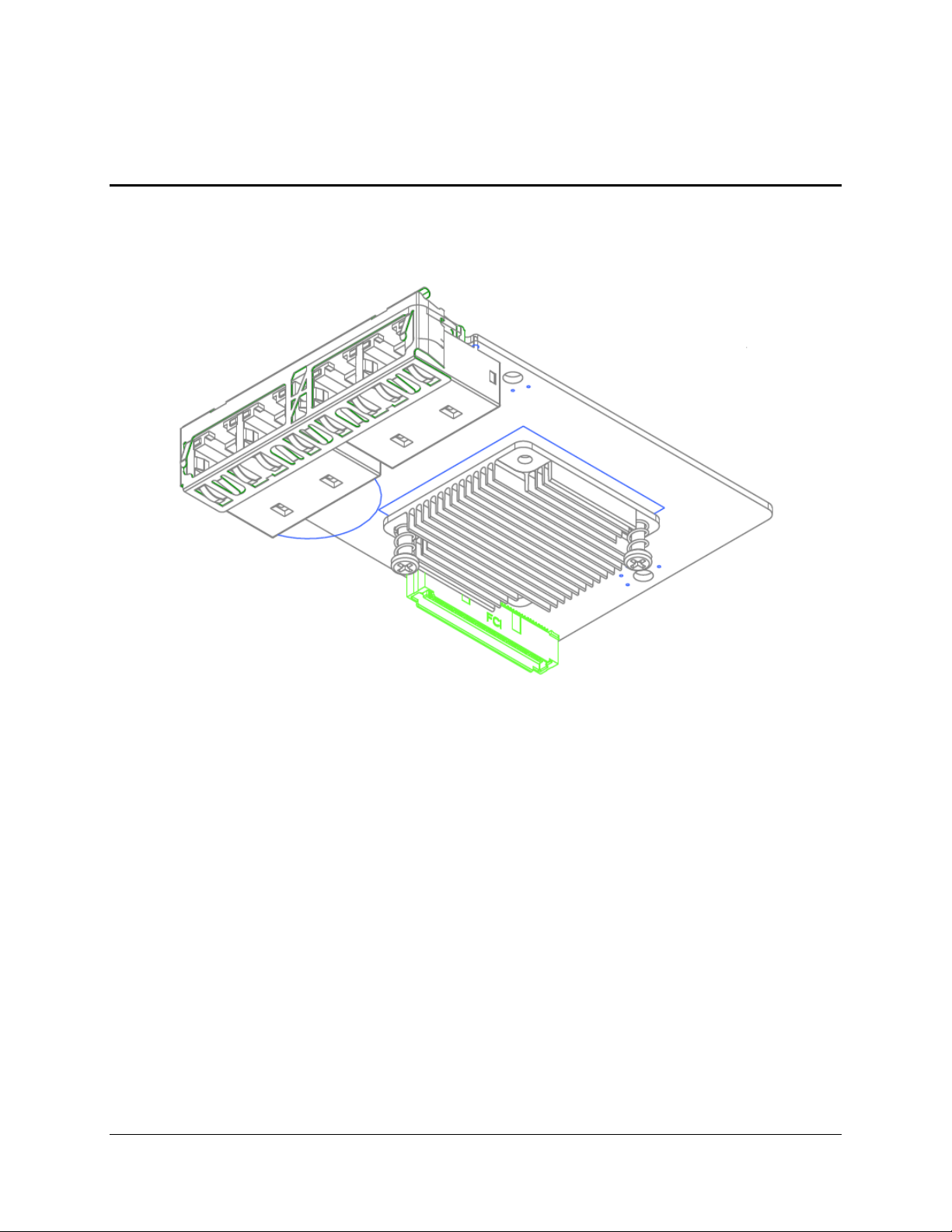
The Quad Port Intel® I350 GbE I/O Module provides four additional 10/100/1000Mbit external
connections. This section provides a high-level description of the implementation of this I/O
module.
Figure 1. Quad Port Intel® I350 GbE I/O Module
2.1 Feature Set
The Quad Port Intel® I350 GbE I/O Module supports the following feature set:
Intel® I350 Controller 17x17mm chip
Quad 1Gb RJ45 Ethernet external connections
Speed and Link/Act LEDs for each RJ45 connection
Onboard 1.0V VR off of 12V and 5V_SB Rails
One WOL port operating in 1 GB mode is supported (Port 2)
1.8V_SB linear VR off 3.3V_SB
256kb LAN EEPROM and 1Mb SPI Flash (SPI Flash unstuffed as baseboard BIOS will
provide OpROM for PXE and iSCSI support)
Three loose screws to mount IOM directly to sheet metal chassis. It's recommended to
use same screws as used to install the baseboard
256Byte FRU EEPROM and TMP75 temp sensor
Revision 1.1
Intel order number: G30021-004
Page 11
Quad Port Intel® I350 GbE I/O Module Intel® I/O Expansion Modules for Intel® Platforms HWS
4
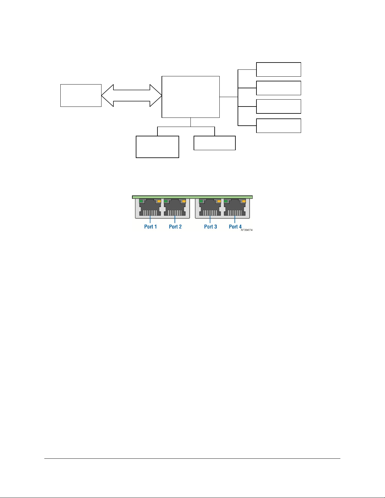
Intel® I350
2 x 40-pin
connector
NIC Port 1
PCIe Gen2 x4
SPI Flash
(empty)
EEPROM
NIC Port 2
NIC Port 3
NIC Port 4
2.2 Functional Block Diagram
Figure 2. Quad Port Intel® I350 GbE I/O Module Block Diagram
Figure 3. Quad Port Intel® I350 GbE I/O Port Identification
Revision 1.1
Intel order number: G30021-004
Page 12
Intel® I/O Expansion Modules for Intel® Platforms HWS Quad Port Intel® I350 GbE I/O Module
5
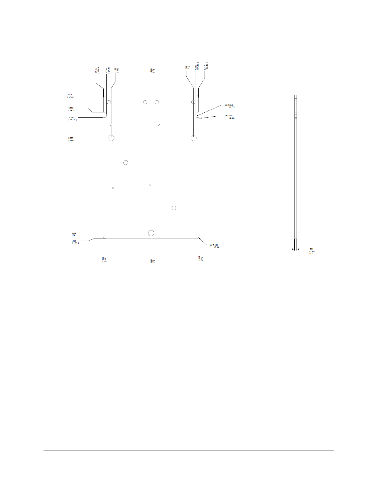
2.3 Mechanical Dimensions
Figure 4. Quad Port Intel® I350 GbE I/O Module Dimensions; Top and Side Views
Revision 1.1
Intel order number: G30021-004
Page 13

Quad Port Intel® I350 GbE I/O Module Intel® I/O Expansion Modules for Intel® Platforms HWS
6
Figure 5. Quad Port Intel® I350 GbE I/O Module Dimensions; Bottom View
2.4 Intel
®
I350 Gb Ethernet Controller
The Intel® Ethernet Controller I350 is a single, compact, low power component that supports
quad port and dual port gigabit Ethernet designs. The device offers four fully-integrated gigabit
Ethernet media access control (MAC), physical layer (PHY) ports and four SGMII/SerDes ports
that can be connected to an external PHY. The I350 supports PCI Express* (PCIe v2.1
(2.5GT/s and 5GT/s)).
The device enables two-port or four-port 1000BASE-T implementations using integrated PHYs.
It can be used for server system configurations such as rack mounted or pedestal servers, in an
add-on NIC or LAN on Motherboard (LOM) design. Another possible system configuration is for
blade servers. Here, the I350 can support up to four SerDes ports as LOM or mezzanine card.
It can also be used in embedded applications such as switch add-on cards and network
appliances.
Revision 1.1
Intel order number: G30021-004
Page 14

Intel® I/O Expansion Modules for Intel® Platforms HWS Quad Port Intel® I350 GbE I/O Module
7
1. External Interfaces provided
PCIe v2.1 (2.5GT/s and 5GT/s) x4/x2/x1
MDI (Copper) standard IEEE 802.3 Ethernet interface for 1000BASE-T, 100BASE-TX,
and 10BASE-T applications (802.3, 802.3u, and 802.3ab)
Serializer-Deserializer (SERDES) to support 1000BASE-SX/LX (optical fiber -
IEEE802.3)
Serializer-Deserializer (SERDES) to support 1000BASE-KX(802.3ap) and 1000BASE-
BX (PICMIG 3.1) for Gigabit backplane applications
SGMII (Serial-GMII Specification) interface for SFP (SFP MSA INF-8074i)/external PHY
connections
NC-SI (DMTF NC-SI) or SMBus for Manageability connection to BMC
IEEE 1149.6 JTAG
2. Performance Enhancements
PCIe v2.1 TLP Process Hints (TPH)
UDP, TCP and IP Checksum offload
UDP and TCP Transmit Segmentation Offload (TSO)
SCTP receive and transmit checksum offload
3. Virtualization ready
Next Generation VMDq support (8 VMs)
Support of up to 8 VMs per port (1 queue allocated to each VM)
PCI-SIG I/O SR-IOV support (Direct assignment)
Queues per port: 8 TX and 8 RX queues
4. Power saving features
Advanced Configuration and Power Interface (ACPI) power management states and
wake-up capability
Advanced Power Management (APM) wake-up functionality
Low power link-disconnect state
PCIe v2.1 LTR
DMA Coalescing for improved system power management
EEE (IEEE802.3az) for reduced power consumption during low link utilization periods
5. IEEE802.1AS - Timing and Synchronization
IEEE 1588 Precision Time Protocol support
Per-packet timestamp
6. Total Cost of Ownership (TCO)
IPMI BMC pass-thru; multi-drop NC-SI
Internal BMC to OS and OS to BMC traffic support
7. Additional product details
17x17 (256 Balls) or 25x25 (576 Balls) PBGA package
Estimated power: 2.8W (max) in dual port mode and 4.2W (max) in quad port mode
Memories have Parity or ECC protection
See Intel® Ethernet Controller I350 Datasheet for more details.
Revision 1.1
Intel order number: G30021-004
Page 15

Dual Port Intel® X540 10GbE I/O Module Intel® I/O Expansion Modules for Intel® Platforms HWS
8
3. Dual Port Intel
(AXX10GBTWLIOM and AXX10GBTWLHW)
®
X540 10GbE I/O Module
Figure 6. Dual Port Intel® X540 10GbE I/O Module
3.1 Feature Set
Following is the feature set:
Intel® X540 Controller 25x25mm chip
Two 10Gb RJ45 Ethernet external connections
Support PXE and iSCSI
WOL support of one 1GbE port
Speed and Link/Act LEDs for each 10Gb RJ45 connection
16M bit SPI Flash
256Byte FRU EEPROM and TMP75 temp sensor
Stainless steel EMI shield
AXX10GBTWLHW is the same with AXX10GBTWLIOM except for the heat sink to fit
Intel® Server Board S2600JF, S2600WP, and Intel® Server Chassis H2000 Family.
Revision 1.1
Intel order number: G30021-004
Page 16

Intel® I/O Expansion Modules for Intel® Platforms HWS Dual Port Intel® X540 10GbE I/O Module
9
Intel® X540
2 x 40-pin
connector
NIC Port 1
PCIe Gen2 x8
SPI Flash
NIC Port 2
3.2 Functional Block Diagram
Figure 7. Dual Port Intel® X540 10GbE I/O Module Block Diagram
Figure 8. Dual Port Intel® X540 10GbE I/O Module Port Identification
Revision 1.1
Intel order number: G30021-004
Page 17

Dual Port Intel® X540 10GbE I/O Module Intel® I/O Expansion Modules for Intel® Platforms HWS
10
3.3 Mechanical Dimensions
Figure 9. Dual Port Intel® X540 10GbE I/O Module Dimensions; Top and side View
Revision 1.1
Intel order number: G30021-004
Page 18

Intel® I/O Expansion Modules for Intel® Platforms HWS Dual Port Intel® X540 10GbE I/O Module
11
Figure 10. Dual Port Intel® X540 10GbE I/O Module Dimensions; Bottom View
Revision 1.1
Intel order number: G30021-004
Page 19

Dual Port Intel® X540 10GbE I/O Module Intel® I/O Expansion Modules for Intel® Platforms HWS
12
3.4 Intel
®
X540 10Gb Ethernet Controller
1. General
Serial flash interface
Device disable capability
Package size - 25 mm x 25 mm
2. Networking
10 GbE/1 GbE/100 Mb/s copper PHYs integrated on-chip
Support for jumbo frames of up to 15.5 KB
Flow control support: send/receive pause frames and receive FIFO thresholds
Statistics for management and RMON
802.1q VLAN support
TCP segmentation offload: up to 256 KB
IPv6 support for IP/TCP and IP/UDP receive checksum offload
Fragmented UDP checksum offload for packet reassembly
Message Signaled Interrupts (MSI)
Message Signaled Interrupts (MSI-X)
Interrupt throttling control to limit maximum interrupt rate and improve CPU usage
Receive packet split header
Multiple Receive Queues (RSS) 8x8 and 16x4
32 transmit queues
Receive header replication
Dynamic interrupt moderation
DCA support
TCP timer interrupts
No snoop
Relaxed ordering
Support for 16 Virtual Machines Device Queues (VMDq) per port
3. Host Interface
PCIe base specification 2.1 (2.5GT/s or 5GT/s)
Bus width — x1, x2, x4, x8
64-bit address support for systems using more than 4 GB of physical memory
4. MAC Functions
Descriptor ring management hardware for transmit and receive
ACPI register set and power down functionality supportingD0 and D3 states
A mechanism for delaying/reducing transmit interrupts
Software-controlled global reset bit (resets everything except the configuration registers)
Four Software-Definable Pins (SDP) per port
Wake up
IPv6 wake-up filters
Configurable flexible filter (through NVM)
LAN function disable capability
Programmable memory transmit buffers (160 KB/port)
Default configuration by NVM for all LEDs for pre-driver functionality
5. Manageability
Eight VLAN L2 filters
16 Flex L3 port filters
Revision 1.1
Intel order number: G30021-004
Page 20

Intel® I/O Expansion Modules for Intel® Platforms HWS Dual Port Intel® X540 10GbE I/O Module
13
Four Flexible TCO filters
Four L3 address filters (IPv4)
Advanced pass through-compatible management packet transmit/receive support
SMBus interface to an external Manageability Controller (MC)
NC-SI interface to an external MC
Four L3 address filters (IPv6)
Four L2 address filters
See Intel® Ethernet Controller 10G X540 Datasheet for more details.
Revision 1.1
Intel order number: G30021-004
Page 21

Dual Port Intel® 82599 10GbE I/O Module Intel® I/O Expansion Modules for Intel® Platforms HWS
14
4. Dual Port Intel
(AXX10GBNIAIOM)
®
82599 10GbE I/O Module
Figure 11. Dual Port Intel® 82599 10GbE I/O Module
4.1 Feature Set
Following is the feature set:
Intel® 82599 10GbE Controller 25x25mm chip
Two 10Gb SFP+ Ethernet external connections
Speed and Link/Act LEDs for each 10Gb SFP+ connection
Support PXE, iSCSI, and FCoE functionalities
256k bit LAN EEPROM and 4Mbit SPI Flash
256 Byte FRU EEPROM and TMP75 temp sensor
The following SFP+ modules are supported:
- Intel® Ethernet SFP+ SR Optics E10GSFPSR
- Intel® Ethernet SFP+ LR Optics E10GSFPLR
Revision 1.1
Intel order number: G30021-004
Page 22

Intel® I/O Expansion Modules for Intel® Platforms HWS Dual Port Intel® 82599 10GbE I/O Module
15
Intel® 82599
2 x 40-pin
connector
SFP+
Connector 1
PCIe Gen2 x8
SPI Flash
EEPROM
SFP+
Connector 2
4.2 Functional Block Diagram
Figure 12. Dual Port Intel® 82599 10GbE I/O Module Block Diagram
Figure 13. Dual Port Intel® 82599 10GbE I/O Module Port Identification
Revision 1.1
Intel order number: G30021-004
Page 23

Dual Port Intel® 82599 10GbE I/O Module Intel® I/O Expansion Modules for Intel® Platforms HWS
16
4.3 Mechanical Dimensions
Figure 14. Dual Port Intel® 82599 10GbE I/O Module Dimensions; Top and side View
Revision 1.1
Intel order number: G30021-004
Page 24

Intel® I/O Expansion Modules for Intel® Platforms HWS Dual Port Intel® 82599 10GbE I/O Module
17
Figure 15. Dual Port Intel® 82599 10GbE I/O Module Dimensions; Bottom View
Revision 1.1
Intel order number: G30021-004
Page 25

Dual Port Intel® 82599 10GbE I/O Module Intel® I/O Expansion Modules for Intel® Platforms HWS
18
4.4 Intel
®
82599 10Gb Ethernet Controller
1. General
Serial Flash Interface
4-wire SPI EEPROM Interface
Protected EEPROM space for private configuration
Device disable capability
Package Size - 25 mm x 25 mm
2. Networking
Complies with the 10 Gb/s and 1 Gb/s Ethernet/802.3ap (KX/KX4/KR) specification
Complies with the 10 Gb/s Ethernet/802.3ae (XAUI) specification
Complies with the 1000BASE-BX specification
Complies with the IEEE 802.3x 100BASE-TX specification
Support for jumbo frames of up to 15.5 KB
Auto negotiation Clause 73 for supported mode
CX4 per 802.3ak
Flow control support: send/receive pause frames and receive FIFO thresholds
Statistics for management and RMON
802.1q VLAN support
TCP segmentation offload: up to 256 KB
IPv6 support for IP/TCP and IP/UDP receive checksum offload
Fragmented UDP checksum offload for packet reassembly
Message Signaled Interrupts (MSI)
Message Signaled Interrupts (MSI-X)
Interrupt throttling control to limit maximum interrupt rate and improve CPU usage
Receive packet split header
Multiple receive queues (Flow Director) 16 x 8 and 32 x 4
128 transmit queues
Receive header replication
Dynamic interrupt moderation
DCA support
TCP timer interrupts
NO snoop
Relaxed ordering
Support for 64 virtual machines per port (64 VMs x 2 queues)
Support for Data Center Bridging (DCB) (802.1Qaz, 802.1Qbb, 802.1p)
3. Host Interface
PCIe Base Specification 2.0 (2.5GT/s) or (5GT/s)
Bus width — x1, x2, x4, x8
64-bit address support for systems using more than 4 GB of physical memory
4. MAC Functions
Descriptor ring management hardware for transmit and receive
ACPI register set and power down functionality supportingD0 and D3 states
A mechanism for delaying/reducing transmit interrupts
Software-controlled global reset bit (resets everything except the configuration registers)
Eight Software-Definable Pins (SDP) per port
Four of the SDP pins can be configured as general-purpose interrupts
Revision 1.1
Intel order number: G30021-004
Page 26

Intel® I/O Expansion Modules for Intel® Platforms HWS Dual Port Intel® 82599 10GbE I/O Module
19
LED Color
LED State
NIC State
Green/Amber (Right)
Off
Not used
Amber
1 Gbps
Green
10 Gbps
Green (Left)
On
Active Connection
Blinking
Transmit / Receive activity
Wake up
Ipv6 wake-up filters
Configurable flexible filter (through EEPROM)
LAN function disable capability
Programmable memory transmit buffers (160 KB/port)
Default configuration by EEPROM for all LEDs for pre-driver functionality
Support for SR-IOV
5. Manageability
Eight VLAN L2 filters
16 flex L3 port filters
Four Flexible TCO filters
Four L3 address filters (IPv4)
Advanced pass through-compatible management packet transmit/receive support
SMBus interface to an external manageability controller
NC-SI interface to an external manageability controller
Four L3 address filters (IPv6)
Four L2 address filters
See Intel® 82599 10 GbE Controller Datasheet for more details.
4.5 LAN LED Functionality
Each of the two SFP+ Ethernet ports on the Dual Port Intel® 82599 10GbE I/O Module will have
both a speed LED and a link/activity LED.
Table 3. Dual Port Intel® 82599 10GbE I/O Module LED Functionality
Revision 1.1
Figure 16. Dual Port Intel® 82599 10GbE I/O Module; Rear View
Intel order number: G30021-004
Page 27

Single Port FDR InfiniBand* ConnectX-3* I/O Module Intel® I/O Expansion Modules for Intel® Platforms HWS
20
5. Single Port FDR InfiniBand* ConnectX*-3 I/O Module
(AXX1FDRIBIOM)
Figure 17. Single Port FDR InfiniBand* ConnectX*-3 I/O Module
5.1 Feature Set
Following is the feature set:
Mellanox* Connect X-3* FDR/10GbE silicon
Single QSFP+ external connector, standard style QSFP+ cage (not PCI) with EMI spring
fingers and with custom heat sink and retention clip for IOM low profile form factor
SMB bus isolation and power control to the QSFP+ external connector
Link (green) and Activity (amber) LEDs for the QSFP+ connection
16Mbit SPI Flash
256Byte FRU EEPROM and TMP75 temp sensor (stuffed)
Stainless steel EMI shield
See Mellanox* Connect X-3* Datasheet for additional silicon and software level features
supported.
Revision 1.1
Intel order number: G30021-004
Page 28

Intel® I/O Expansion Modules for Intel® Platforms HWS Single Port FDR InfiniBand* ConnectX-3* I/O Module
21
InfiniBand*
Controller
ConnectX-3
1.2V VR
1.8V VR
1.0V VR
2 x 40-pin
connector
QSFP+
Port
PCIe Gen3 x8
SPI Flash
16M bits
5.2 Functional Block Diagram
Figure 18. Single Port FDR InfiniBand* ConnectX*-3 I/O Module Block Diagram
Figure 19. Single Port FDR InfiniBand* ConnectX*-3 I/O Module Port Identification
Revision 1.1
Intel order number: G30021-004
Page 29

Single Port FDR InfiniBand* ConnectX-3* I/O Module Intel® I/O Expansion Modules for Intel® Platforms HWS
22
5.3 Mechanical Dimensions
Figure 20. Single Port FDR InfiniBand* ConnectX*-3 I/O Module Dimensions; Top and side View
Revision 1.1
Intel order number: G30021-004
Page 30

Intel® I/O Expansion Modules for Intel® Platforms HWS Single Port FDR InfiniBand* ConnectX-3* I/O Module
23
Figure 21. Single Port FDR InfiniBand* ConnectX*-3 I/O Module Dimensions; Bottom View
5.4 ConnectX*-3 Single/Dual-Port Adapter Silicon with VPI
5.4.1 Overview
ConnectX-3 adapter devices with Virtual Protocol Interconnect (VPI) supporting InfiniBand* and
Ethernet connectivity provide the highest performing and most flexible interconnect solution for
PCI Express Gen3 Blade Server and Landed-on-Motherboard designs used in Enterprise Data
Centers, High-Performance Computing, and Embedded environments.
Clustered data bases, parallel processing, transactional services and high-performance
embedded I/O applications will achieve significant performance improvements resulting in
Revision 1.1
Intel order number: G30021-004
Page 31

Single Port FDR InfiniBand* ConnectX-3* I/O Module Intel® I/O Expansion Modules for Intel® Platforms HWS
24
LED Color
LED State
NIC State
Amber (Right)
Off
No Activity
Blinking
Transmit / Receive Activity
Green (Left)
Off
No Active Link Connection
On
Active Link Connection
reduced completion time and lower cost per operation. ConnectX-3 with VPI also simplifies
system development by serving multiple fabrics with one hardware design.
5.4.2 Key Features
1μs MPI ping latency
Up to 56Gb/s InfiniBand* or 40 Gigabit Ethernet per port
PCI Express 3.0 (up to 8GT/s)
CPU offload of transport operations
Application offload
GPU communication acceleration
Precision Clock Synchronization
End-to-end QoS and congestion control
Hardware-based I/O virtualization
Dynamic power management
Fibre Channel encapsulation (FCoIB or FCoE)
Ethernet encapsulation (EoIB)
17mm X 17mm RoHS-R6
5.5 Network LED Functionality
The QSFP+ port on the Single Port FDR InfiniBand* ConnectX*-3 I/O Module will have a green
LED and amber LED. The following is a mapping of LED color, function, and physical location
with respect to the QSFP+ connector.
Table 4. Single Port FDR InfiniBand* ConnectX*-3 I/O Module LED Functionality
Revision 1.1
Intel order number: G30021-004
Page 32

Intel® I/O Expansion Modules for Intel® Platforms HWS Dual Port FDR InfiniBand* ConnectX*-3 I/O Module
25
6. Dual Port FDR InfiniBand* ConnectX*-3 I/O Module
(AXX2FDRIBIOM)
Figure 22. Dual Port FDR InfiniBand* ConnectX*-3 I/O Module
6.1 Feature Set
Following is the feature set:
Mellanox* Connect X-3* FDR/10GbE silicon
Dual QSFP+ external connectors, standard style QSFP+ cage (not PCI) with EMI spring
fingers and with custom heat sink and retention clip for IOM low profile form factor
SMB bus isolation and power control to the QSFP+ external connector
Link (green) and Activity (amber) LEDs for the QSFP+ connection
16Mbit SPI Flash
256Byte FRU EEPROM and TMP75 temp sensor (stuffed)
Stainless steel EMI shield
See Mellanox* Connect X-3* Datasheet for additional silicon and software level features
supported.
Revision 1.1
Intel order number: G30021-004
Page 33

Dual Port FDR InfiniBand* ConnectX*-3 I/O Module Intel® I/O Expansion Modules for Intel® Platforms HWS
26
InfiniBand*
Controller
ConnectX-3
1.2V VR
1.8V VR
1.0V VR
2 x 40-pin
connector
QSFP+
Port 1
PCIe Gen3 x8
SPI Flash
16M bits
QSFP+
Port 2
6.2 Functional Block Diagram
Figure 23. Dual Port FDR InfiniBand* ConnectX*-3 I/O Module Block Diagram
Figure 24. Dual Port FDR InfiniBand* ConnectX*-3 I/O Module Port Identification
Revision 1.1
Intel order number: G30021-004
Page 34

Intel® I/O Expansion Modules for Intel® Platforms HWS Dual Port FDR InfiniBand* ConnectX*-3 I/O Module
27
6.3 Mechanical Dimensions
Figure 25. Dual Port FDR InfiniBand* ConnectX*-3 I/O Module Dimensions; Top and side View
Revision 1.1
Intel order number: G30021-004
Page 35

Dual Port FDR InfiniBand* ConnectX*-3 I/O Module Intel® I/O Expansion Modules for Intel® Platforms HWS
28
Figure 26. Dual Port FDR InfiniBand* ConnectX*-3 I/O Module Dimensions; Bottom View
6.4 ConnectX*-3 Single/Dual-Port Adapter Silicon with VPI
6.4.1 Overview
ConnectX-3 adapter devices with Virtual Protocol Interconnect (VPI)supporting InfiniBand* and
Ethernet connectivity provide the highest performing and most flexible interconnect solution for
PCI Express Gen3 Blade Server and Landed-on-Motherboard designs used in Enterprise Data
Centers, High-Performance Computing, and Embedded environments.
Clustered data bases, parallel processing, transactional services and high-performance
embedded I/O applications will achieve significant performance improvements resulting in
Revision 1.1
Intel order number: G30021-004
Page 36

Intel® I/O Expansion Modules for Intel® Platforms HWS Dual Port FDR InfiniBand* ConnectX*-3 I/O Module
29
LED Color
LED State
NIC State
Amber (Right)
Off
No Activity
Blinking
Transmit / Receive Activity
Green (Left)
Off
No Active Link Connection
On
Active Link Connection
reduced completion time and lower cost per operation. ConnectX-3 with VPI also simplifies
system development by serving multiple fabrics with one hardware design.
6.4.2 Key Features
1μs MPI ping latency
Up to 56Gb/s InfiniBand* or 40 Gigabit Ethernet per port
PCI Express 3.0 (up to 8GT/s)
CPU offload of transport operations
Application offload
GPU communication acceleration
Precision Clock Synchronization
End-to-end QoS and congestion control
Hardware-based I/O virtualization
Dynamic power management
Fibre Channel encapsulation (FCoIB or FCoE)
Ethernet encapsulation (EoIB)
17mm X 17mm RoHS-R6
Note: Due to PCIe3 x8 bandwidth limitation, both ports cannot run simultaneously at full speed.
6.5 Network LED Functionality
The QSFP+ port on the Dual Port FDR InfiniBand* ConnectX*-3 I/O Module will have a green
LED and an amber LED. Below is a mapping of LED color, function, and physical location with
respect to the QSFP+ connector.
Table 5. Dual Port FDR InfiniBand* ConnectX*-3 I/O Module LED Functionality
Revision 1.1
Intel order number: G30021-004
Page 37

Mouser Electronics
Authorized Distributor
Click to View Pricing, Inventory, Delivery & Lifecycle Information:
Intel:
AXX2FDRIBIOM AXX4P1GBPWLIOM AXX10GBTWLHW AXX1FDRIBIOM AXX10GBNIAIOM AXX10GBTWLIOM
 Loading...