

Page 1

Intel® Pentium® 4 LGA775 / mPGA478
AMD K8(939/754) / K7
Installation Guide
GH-PDU21-MF
REV.1002
050318
Page 2
English
Table of Content
Checklist............................................................................................................3
Specification.......................................................................................................4
Feature..............................................................................................................4
Warranty Item.....................................................................................................5
Precautions........................................................................................................5
Installation Instructions for Fan Control Box & Power Cable.......................................6
Power Installation and 3.5” Fan Speed Controller Installation.......................................7
Power Installation and PCI Fan Speed Controller Installation.......................................8
Installation Instructions for P4 LGA775RM & Cooler...................................................9
Installation Instructions for Intel® Pentium® 4 mPGA478 Clips....................................10
Installation Instructions for AMD K8 (939 / 754) Clip..................................................11
Installation Instructions for AMD K7 Clip.................................................................12
GH-PDU21-MF
- 2 -
Page 3
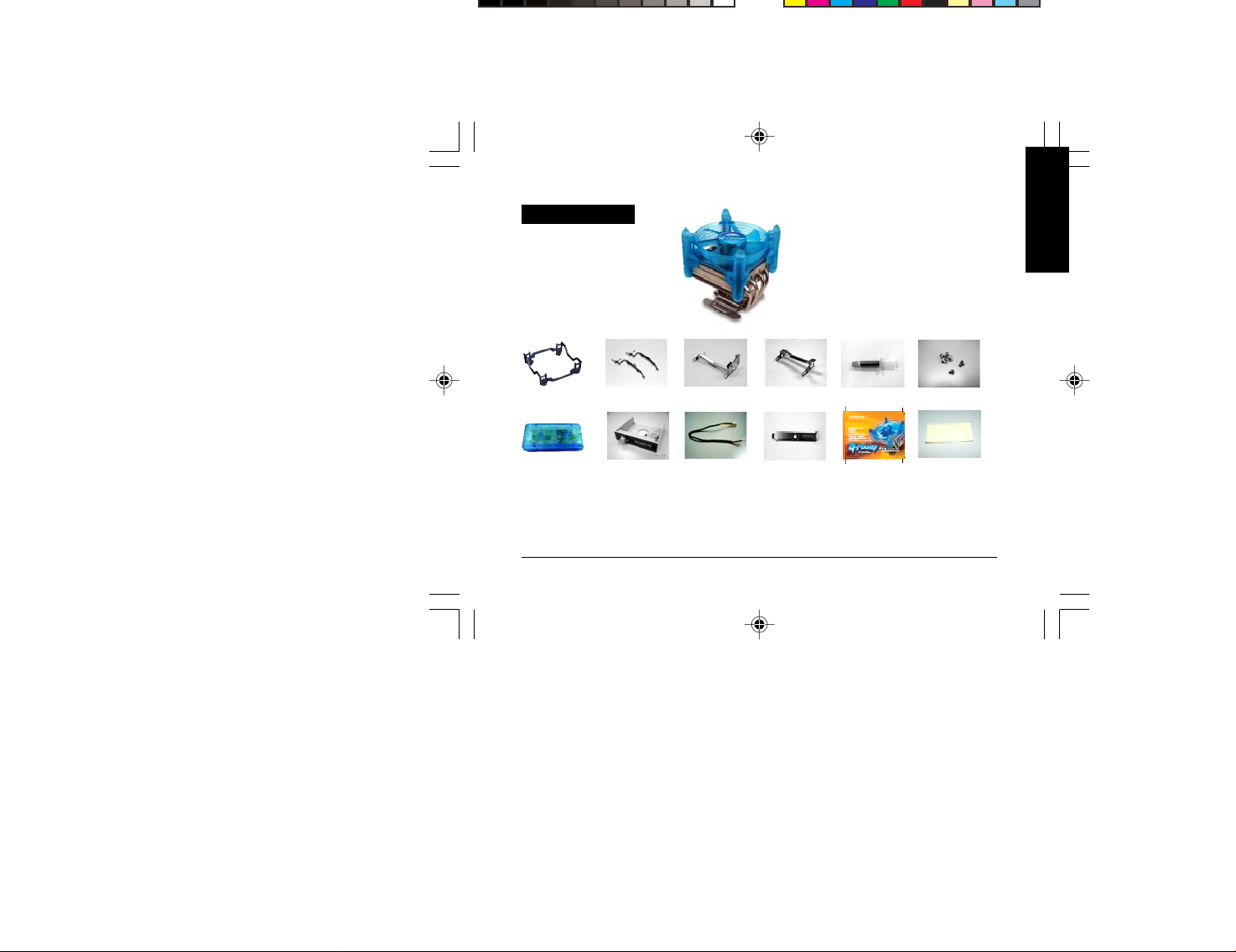
Checklist
English
(1)GH-PDU21 -MF Cooler
(2)LGA775 RM
(8) Fan control box
<note1> The double-sided adhesive strip is to attach the fan control box to the chassis.
(3) P4 clips
(9) Speed control
& 3.5” bracket
(4) K8 clip
(5) K7 clip
(11) PCI bracket (10) Power cable
- 3 -
(6) Heat sink paste
(12) GH-PDU21-MF
user's manual
(7) Screw
(13) Double-sided
adhesive strip
(note1)
GH-PDU21-MF
Page 4
Specification
English
y Heat Sink Dimension : 110x1 10 x 109mm
y Heatpipe Number : 4
y Fan Speed : 1,700~3,200 rpm
y Rated Voltage : 12V
y Noise :21.3 ~ 40.1 dBA
y Bearing Type: Ball Bearing
y Base Maerial : Copper w/ Ni coating
y Fin Material : Al fin
y Rated Current : 0.1 ~ 0.5A
y Airflow : 36.2 ~ 68.5 CFM
y Life Expectancy : 50,000 hr
y Total W eight : 430g
y Application :
®
Intel
Pentium® 4 LGA775 840 / 670 / 570(3.8GHz)
®
Intel
Pentium® 4 478 3.4GHz
AMD Athlon
AMD K7 3200+
Feature
y Unique and patented cooler bracket design for Intel
/ K7 Platform
y 4 heatpipe design
y Adjustable fan speed control panel
y High airflow fan w/ VR function (1,700~3,200 rpm)
y Unique fan frame design sustained by 4 artistic pillars
y Brilliant Blue LEDS
y Omni- directional cooler design
y Linear fan speed control module, suitable for both 3.5” front panel and PCI rear panel
y Easy clip installation – No tool required
GH-PDU21-MF
®
Pentium®4 LGA775 / mPGA 478 / AMD K8( 939/ 754 )
- 4 -
TM
FX55 / AMD AthlonTM XP 4000+
Page 5
Precautions
The cooler fan speed levels provided are for reference use only. Please refer to the motherboard BIOS to verify
actual fan speed levels.
Each connector on the fan control box is foolproof. Read the user’s manual before use.
Before use, please remove the bottom protective layer of the cooler.
Please make sure the computer is turned off and its power disconnected prior to installation.
Warranty Item
<Warranty coverage does not include the following>
Incorrect method of operation or use of product not for intended use
Operational use beyond the advised standards (eg. overclocking)
Inability to install the product as a result of incompatibility with the motherboard used
Damage of product as a result of other product components
Any form of alteration to original product
A faulty product that leads to harm or damage to other products
Damage caused by natural disasters (eg. earthquake, fire, flood)
Products with a warranty sticker that is removed, torn or unreadable
Due to the weight of the cooler exceeding normal standards, please remove the cooler before computer transport to
prevent damage to the cooler itself as well as prevent problems during installtion.
English
- 5 -
GH-PDU21-MF
Page 6
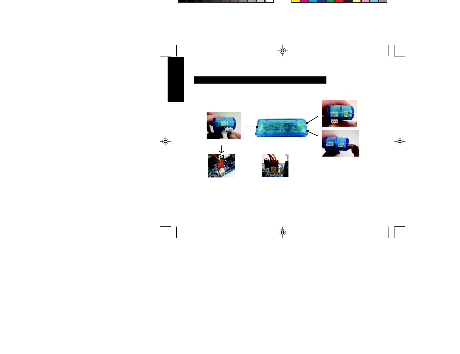
Installation Instructions for Fan Control Box & Power Cable
English
Connector for 3.5
controller
Fan Speed
Power Cable connector
Connect the other end of the power
cable to the 3-pin CPU fan header
on the motherboard.
GH-PDU21-MF
Fan Control Box
o r
Connect the other end of the power
cable to the 4-pin CPU fan header
on the motherboard. (LGA775)
- 6 -
Power connector for Cooler
Page 7
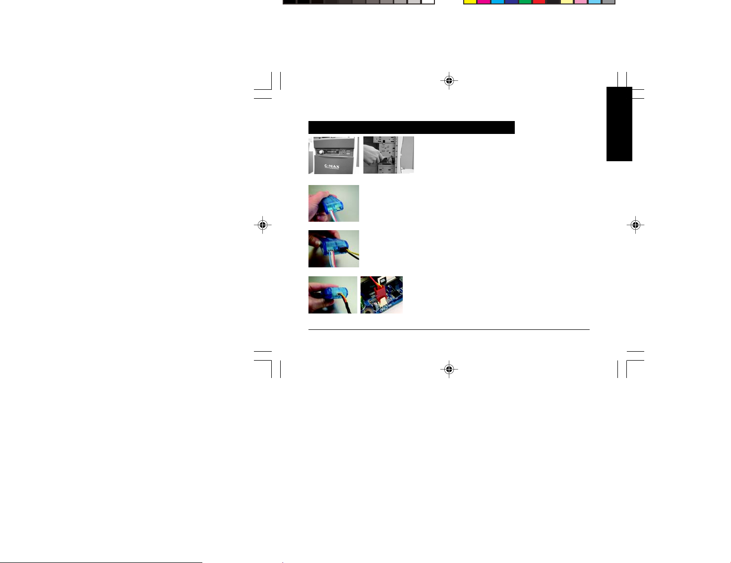
Power Installation and 3.5” Fan Speed Controller Installation
Figure 1
Securely hold the 3.5” fan speed controller bracket in place with
the screws provided(Figure 1-1).
English
Figure 1-1
Figure 4-1
Figure 1-2
Figure 2-1
Figure 3-1
Figure 4-2
Figure 2
Connect the cable connector of the 3.5" fan speed controller
to the fan control box (Figure 2-1).
Figure 3
Connect the power cable connector of the cooler to the fan
control box (Figure 3-1).
Figure 4
Assure that one end of the power cable included with the
GH-PDU21-MF cooler is connected to the fan control box
(Figure 4-1). Connect the other end to the CPU fan header on
the motherboard. Then the installation is completed .
(Figure 4-2).
- 7 -
GH-PDU21-MF
Page 8
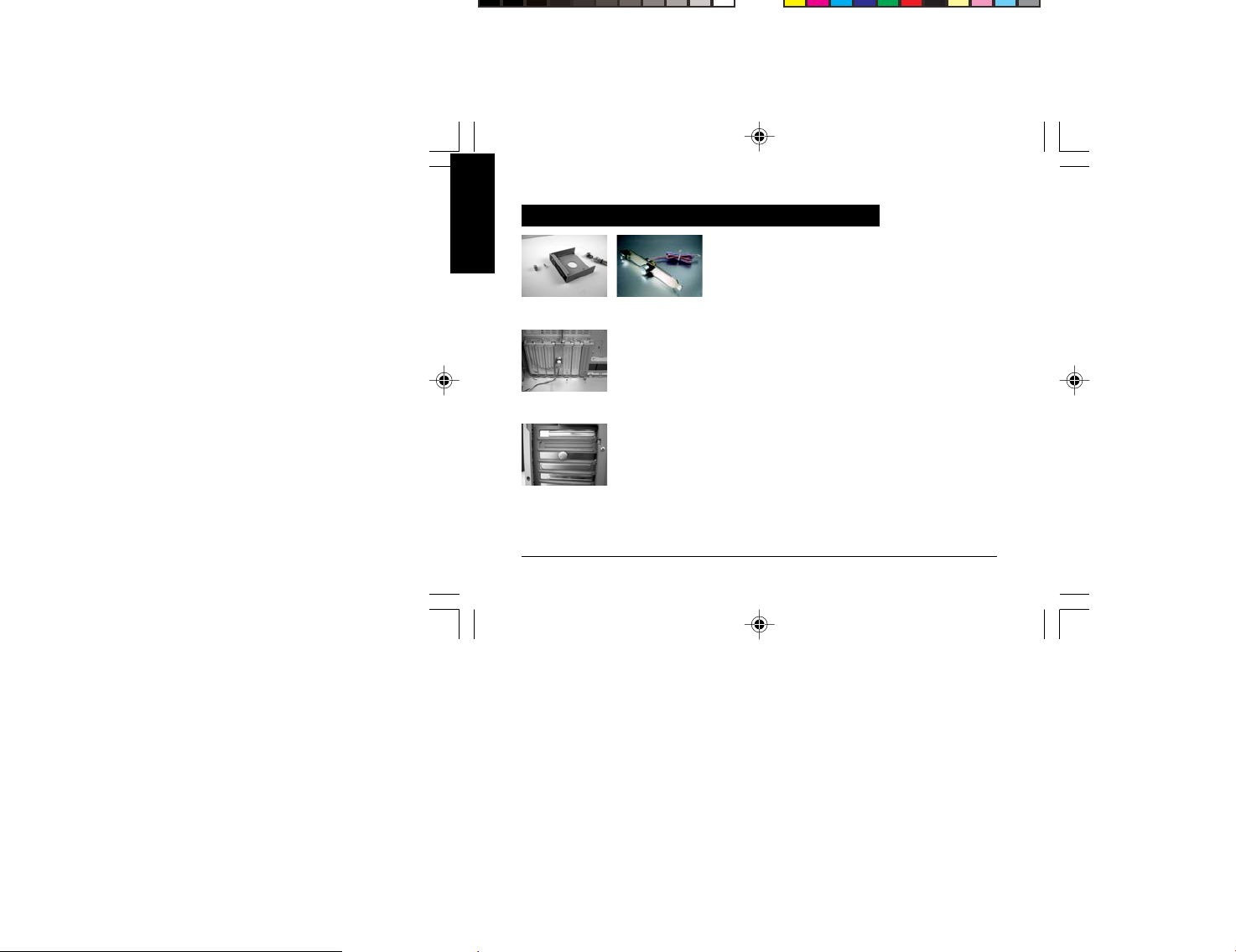
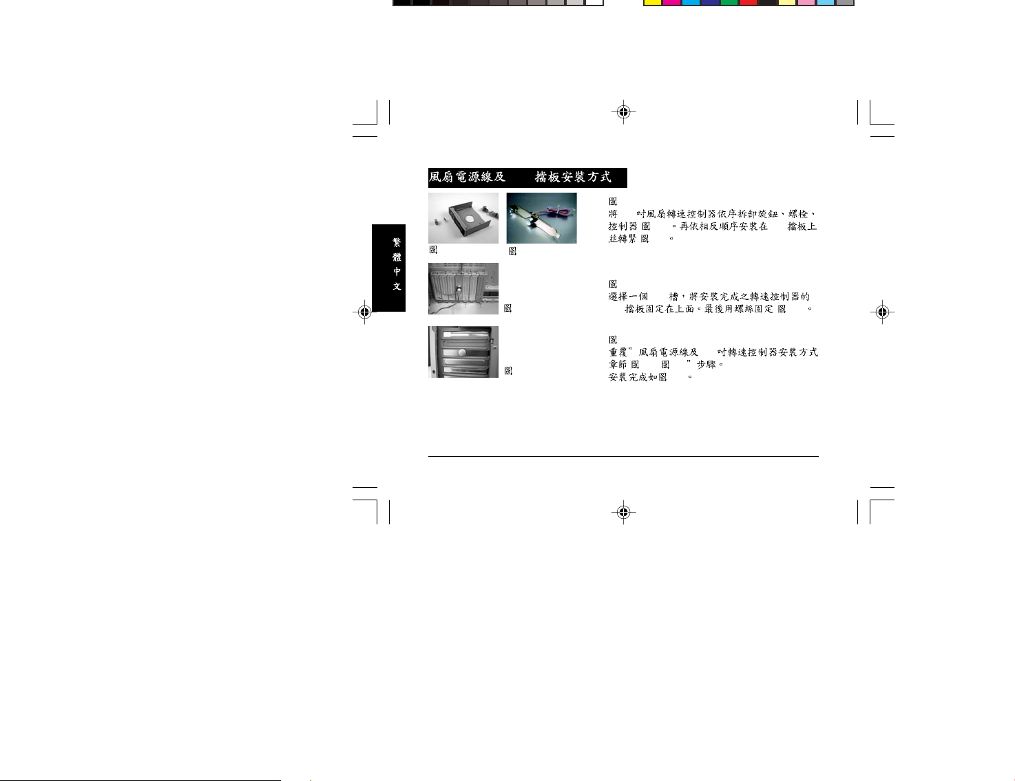
Power Installation and PCI Fan Speed Controller Installation
English
Figure 1
Disassemble the turn knob, bolt and fan speed controller from
the 3.5” bracket and reassemble these parts onto a PCI bracket
Figure 1-1
Figure 1-2
Figure 2-1
Figure 3-1
in sequence.
Figure 2
Place the PCI bracket with the fan speed controller in the
selected PCI slot. Use screws to secure the PCI bracket in
place.
Figure 3
Repeat the steps in “Power Installation and 3.5” Fan Speed
Controller Installation (Figure 2-1~Figure 4-2)”.
The installation is now completed.
GH-PDU21-MF
- 8 -
Page 9

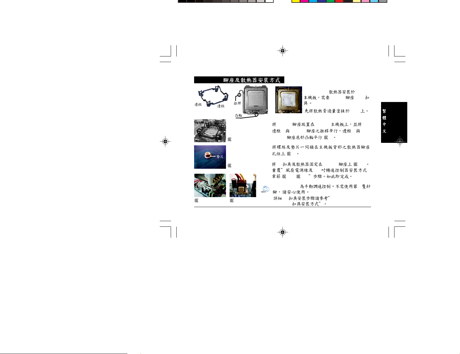
Installation Instructions for P4 LGA775RM & Cooler
Side A
Figure3- 1
Plastic
Washers
Side B
ARM
CAM
Figure 1
Figure 2
Figure3-2
Figure 1
Place the LGA775RM onto the LGA775 motherboard so that
side A is parallel with ARM and side B is parallel with CAM.
Figure 2
From the underside of the motherboard, use screws (4) and
plastic washers (4) together to secure the LGA775RM into
place..
Figure 3
Gently push down on the cooler unit to lock it into position.
(Figure3-1).Repeat the steps in “Power Installation and 3.5”
Fan Speed Controller Installation (Figure 2-1~Figure 4-2)”.
The installation is now completed.
GH-PDU21-MF provides manual fan speed control function. The
fourth pin of the 4-pin CPU fan header does not necessarily have
to be connected (Figure 3-2).
Note: About P4 Clips installation, please refer to “Installation
Instructions for Intel® Pentium®4 mPGA478 Clips”
- 9 -
English
T o install GH-PDU21-MF on LGA775
motherboard needs both LGA775 RM & P4
clips.
Please add an adequate layer of heat sink
paste on the surface of the CPU.
GH-PDU21-MF
Page 10

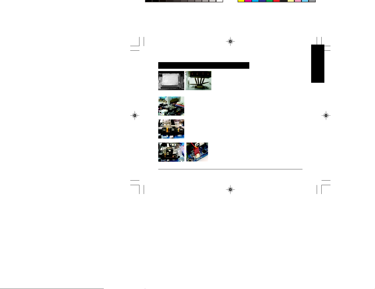
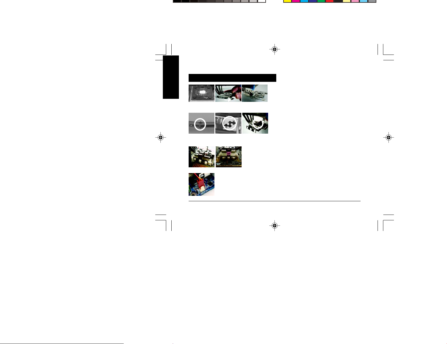
Installation Instructions for Intel® Pentium® 4 mPGA478 Clips
English
Figure 1-1
Figure 3-1
Figure 1-2
C
B
A
Figure 2
Figure 3-2
Figure 4
Figure 1
Please add an adequate layer of heat sink paste on the surface
of the CPU(Figure1-1). Figure 1-2 showing the correct
installation of the cooler atop the CPU.
Figure 2
Clip introduction-Part A: Secured to the retention mechanism hook.
Part B: Tightly contact the cooler bracket.
Part C: Secured to the retention mechanism hook.
Figure 3
Secure Parts A, B, and then C of the clip to the retention
mechanism. Assure that Part C is secured to the retention
mechanism hook on the same side as the heat pipes.
Figure 4
Repeat the steps in “Power Installation and 3.5”
Fan Speed Controller Installation (Figure 2-1~Figure 4-2)”.
The installation is now completed.
GH-PDU21-MF
- 10 -
Page 11
Installation Instructions for AMD K8 (939 / 754) Clip
Figure 1
Please add an adequate layer of heat sink paste on the surface
Figure 1-1
Figure 4-1
Figure 1-2
Figure 2
Figure 3
Figure 4-2
of the CPU.
Figure 2
Figure showing the correct installation of the cooler atop the
CPU.
Figure 3
Align the three insert spaces of the clip with the three juts on
the CPU socket and then push firmly downwards to hold the
clip in space.
Figure 4
Push the lever on the side of the cooler towards the lever
position on the base of the CPU to secure the cooler atop the
CPU. Repeat the steps in “Power Installation and 3.5”
Fan Speed Controller Installation (Figure 2-1~Figure 4-2)”.
The installation is now completed.
- 11 -
English
GH-PDU21-MF
Page 12
Installation Instructions for AMD K7 Clip
English
Figure 1-1
Figure 2-1
GH-PDU21-MF
Figure 1-2 Figure 1-3
A
B
Figure 2-2
Figure 4
Figure 3
Figure 2-3
Figure 1
Please add an adequate layer of heat sink paste on the
surface of the CPU. Remove the bracket of the cooler along
the direction of the arrow (Figure 1-2). The bracket should
be removed as that shown in Figure 1-3.
Figure 2
Place point A of the clip (Figure2-1)on point B at the bottom
of the cooler(Figure2-2).As Figure 2-3.
Figure 3
Align the three spaces on the cooler with the three clips on
the base of the CPU and make sure point A of the clip
(Figure 2-1) is placed on point B at the bottom of the cooler
(Figure 2-2) and push down on the clip until it’s firmly
locked.
Figure 4
Repeat the steps in “Power Installation and 3.5”
Fan Speed Controller Installation (Figure 2-1~Figure 4-2)”.
The installation is now completed.
- 12 -
Page 13

Intel® Pentium® 4 LGA775 / mPGA478
AMD K8 (939 / 754) / K7
GH-PDU21-MF
Page 14

.......................................................................................................15
.......................................................................................................16
.......................................................................................................16
.......................................................................................................17
.......................................................................................................17
....................................................................18
3.5 ...................................................19
PCI ................................................................20
P4 LGA775
...............................................................21
Intel® Pentium® 4 mPGA478 ........................................................22
AMD K8 (939 / 754) ..................................................................23
AMD K7
GH-PDU21-MF
..................................................................................24
- 14 -
Page 15

(1) GH-PDU21-MF
(2) LGA775
(8)
(3) P4
(9) 3.5
(4) K8
(10)
- 15 -
(5) K7
(11)PCI
(6)
(12) GH-PDU21-MF
(7)
(13) ( 1)
GH-PDU21-MF
Page 16

y : 110 x 110 x 109 mm
y
: 4
y : 1,700 ~ 3,200 rpm
y
y
y
y
: 12V
: 21.3 ~40.1 dBA
: Ball Bearing
:
y : Aluminum
y
y : 36.2 ~ 68.5 CFM
y
y
y
: 0.1~ 0.5
: 50,000 hr
: 430g
:
®
Intel
Pentium® 4 LGA775 840 / 670 / 570(3.8GHz)
®
Intel
Pentium® 4 478 3.4GHz
TM
AMD Athlon
FX55 / AMD AthlonTM XP 4000+
AMD K7 3200+
y P4 LGA775 P4 mPGA478 AMDK8(939 / 754) AMDK7
y
y 4
y (1,700~3,200 rpm)
y
3.5 PCI
y LED
y
y
y
GH-PDU21-MF
- 16 -
Page 17

BIOS
- 17 -
GH-PDU21-MF
Page 18

GH-PDU21-MF
3.5
3 pin CPU fan 4 pin CPU fan (LGA775)
- 18 -
Page 19

1-1
3.5
1-2
2-1
1
3.5
( 1-2)
2
3.5
( 2-1)
3
4-1
3-1
4-2
( 3-1)
4
GH-PDU21-MF
( 4-1) ( 4-2)
- 19 -
CPU fan
GH-PDU21-MF
Page 20
1-1
PCI
1-2
2-1
1
3.5
( 1-1) PCI
( 1-2)
2
PCI
PCI ( 2-1)
GH-PDU21-MF
3-1
3
3.5
( 2-1~ 4-2)
3-1
- 20 -
Page 21
P4 LGA775
3-1
GH-PDU21-MF LGA775
LGA775 & P4
A
B
CPU
LGA775 LGA775
A LGA775 B
1
LGA775 ( 1)
( 2)
2
P4 LGA775 ( 3-1)
3.5
( 2-1~ 4-2)
GH-PDU21-MF 4
3-2
P4 Intel® Pentium®4
mPGA478
- 21 -
GH-PDU21-MF
Page 22

Intel® Pentium® 4 mPGA478
1-1
C
3-1
GH-PDU21-MF
1
CPU ( 1-2)
1-2
2
B
A
2
3-2
4
A :
B :
C :
3
4
( 2-1~ 4-2)
- 22 -
CPU ( 1-1)
(A B C )
C
3.5
Page 23

AMD K8 (939 / 754)
1-1
4-1
1-2
2
3
4-2
- 23 -
1
CPU
( 1-2)
2
CPU
3
CPU
4
CPU
3.5
( 2-1~ 4-2)
GH-PDU21-MF
Page 24

AMD K7
1-1
2-1
1
1-2
A
B
2-2
1-3
2-3
3
1-3
2
A ( 2-1) B
( 2-2) 2-3
3
( 2-1) B ( 2-2)
CPU
( 1-2)
CPU
A
GH-PDU21-MF
4
4
- 24 -
( 2-1~ 4-2)
3.5
 Loading...