

Page 1

Intel NetStructure® MPCMM0002 Chassis Management Module
Hardware Technical Product Specification
July 2007
Order Number: 309247-004US
Page 2

Legal Lines and Disclaimers
INFORMATION IN THIS DOCUMENT IS PROVIDED IN CONNECTION WITH INTEL® PRODUCTS. NO LICENSE, EXPRESS OR IMPLIED, BY ESTOPPEL OR
OTHERWISE, TO ANY IN TELLEC TUA L PROPERTY RIGHTS IS GRANTED BY THIS DOCUMENT. EXCEPT AS PROVIDED IN INTEL ’S TERMS AND CONDITIONS
OF SALE FOR SUCH PRODUCTS, INTEL ASSUMES NO LIABILITY WHATSOEVER, AND INTEL DISCLAIMS ANY EXPRESS OR IMPLIED WARRANTY, RELATING
TO SALE AND/OR USE OF INTEL PRODUCTS INCLUDING LIABILITY OR WARRANTIES RELATING TO FITNESS FOR A PARTICULAR PURPOSE,
MERCHANTABILITY, OR INFRINGEMENT OF ANY PATENT, COPYRIGHT OR OTHER INTELLECTUAL PROPERTY RIGHT. Intel products are not intended for
use in medical, life saving, life sustaining, critical control or safety systems, or in nuclear facility applications.
Intel may make changes to specifications and product descriptions at any time, without notice. Designers must not rely on the absence or characteristics
of any features or instructions marked “reserv ed” or “undefined.” Intel reserves these for fut ure definition and shall ha ve no responsibility whatsoever for
conflicts or incompatibilities arising from future changes to them. The information here is subject to change without notice. Do not finalize a design with
this information.
The products described in this document may contain design defects or errors known as errata which may cause the product to deviate from published
specifications. Current characterized errata are available on request.
Contact your local Intel sales office or your distributor to obtain the latest specifications and before placing your product order.
Copies of documents which have an order number and are referenced in this document, or other Intel literature, may be obtained by calling 1-800-548-
4725, or by visiting Intel’s Web Site.
Intel processor numbers are not a measure of performance. Processor numbers differentiate features within each processor family, not across different
processor families. See http://www.intel.com/products/processor_number for details.
BunnyPeople, Celeron, Celeron Inside, Centrino, Centrino logo, Core Inside, FlashFile, i960, InstantIP, Intel, Intel logo, Intel386, Intel486, Inte l7 40 ,
IntelDX2, IntelDX4, IntelSX2, Intel Core, Intel Inside, Intel Inside logo, Intel. Leap ahead., Intel. Leap ahead. logo, Intel NetBurst, Intel NetMerge, In tel
NetStructure, Intel SingleDriver, Intel SpeedStep, Intel StrataFlash, Intel Viiv, Intel vPro, Intel XScale, Itanium, Itanium Inside, MCS, MMX, Oplus,
OverDrive, PDCharm, Pentium, Pentium Inside, skoool, Sound Mark, The Journey Inside, VTune, Xeon, and Xeon Inside are trademarks of Intel
Corporation in the U.S. and other countries.
*Other names and brands may be claimed as the property of others.
Copyright © 2007, Intel Corporation. All rights reserved.
Intel NetStructure® MPCMM0002 Chassis Management Module
Hardware TPS July 2007
2 Order Number: 309247-004US
Page 3

Contents—MPCMM0002 CMM
Contents
1.0 Document Organization.............................................................................................8
1.1 Acronyms and Terms.............................. .................................. .........................10
2.0 Introduction............................................................................................................11
2.1 Architecture Specification...................................................................................11
2.2 User Documentation..........................................................................................11
2.3 Product Definition..............................................................................................11
3.0 Getting Started........................................................................................................ 13
3.1 Installing the CMM.............................................................................................13
4.0 Module Components ................................................................................................15
4.1 Block Diagram ..................................................................................................15
4.2 Intel® 80321 Processor ................................ ..................................................... 17
4.3 Memory ...........................................................................................................19
4.4 Ethernet ..........................................................................................................19
4.5 Serial Port UARTs............................... .................................. .. ...........................19
4.6 FPGA...............................................................................................................20
4.7 Redundancy and Hot Swap CPLD.........................................................................20
4.8 Watchdog Timer................................................................................................20
4.9 Real-Time Clock......................... .. ................................. .................................. ..20
4.10 ADM1026 Controller ..........................................................................................21
4.11 Hot Swap Controller...........................................................................................21
4.12 Ride-Through Support................................. ... .. ................................. ... .. .. ..........21
4.13 IPMB Isolation Logic ..........................................................................................21
5.0 Mechanical Information...........................................................................................24
5.1 Dimensions ...................................................................................................... 24
5.2 Front Panel Hardware ...................................... .. .. ..............................................26
5.3 Rear Connector Placement..................................................................................27
5.4 ESD Discharge Strip ..........................................................................................27
6.0 Backplane Considerations........................................................................................28
6.1 IPMB Routing....................................................................................................28
6.2 CMM Power ...................................................................................................... 28
7.0 Rear Connections ....................................................................................................32
7.1 CMM Connector Pinouts......................................................................................32
7.2 Guide Post........................................................................................................41
7.3 CMM Redundancy..............................................................................................41
8.0 Chassis Data Modules (CDMs)..................................................................................43
8.1 CDM Overview..................................................................................................43
8.2 CDM LED..........................................................................................................43
8.3 CDM Management.............................................................................................43
8.4 CDM Power.......................................................................................................44
8.5 CDM Redundancy..............................................................................................44
9.0 Front Panel.............................................................................................................. 45
9.1 Serial Port Pinouts.......................................................................... .. ... .. ............45
9.2 Ethernet Port Pinouts....................................... .. .................................. .. ............47
9.3 Telco Alarm Connector.......................................................................................48
9.4 Alarm Quiet Switch............................................................................................51
9.5 LEDs................................................................................................................52
10.0 Grounding Considerations .......................................................................................54
July 2007 Hardware TPS
Order Number: 309247-004US 3
Intel NetStructure® MPCMM0002 Chassis Management Module
Page 4

MPCMM0002 CMM—Contents
10.1 ESD Discharge Protection....................................................................................54
10.2 Chassis Ground and Logic Ground.............................. .. .................................... .. ..54
11.0 Thermals..................................................................................................................55
11.1 Processor Heat Sink...........................................................................................55
11.2 Module Orientation.............................................................................................55
11.3 Module Airflow Path ...........................................................................................55
11.4 Airflow Requirements .........................................................................................57
11.5 Board Resistance Curve.............................................. .. .................................. .. ..57
11.6 Thermal Sensors................ .. .................................................................. ............58
12.0 Management Module Specifications..........................................................................59
12.1 Feature Summary..............................................................................................59
12.2 Dimensions and Weight......................................................................................60
12.3 Environmental Characteristics .............................................................................60
12.4 Product Reliability Estimate.................................................................................60
12.5 Agency Certifications..........................................................................................61
13.0 Guidelines for Third Party Chassis Vendors..............................................................62
13.1 High Level Design..............................................................................................62
13.2 IPMB Buses.......................................................................................................63
13.3 GPIO Pins.........................................................................................................66
13.4 Interfacing FRUs to the CMM...............................................................................67
13.5 Intelligent FRUs.................................................................................................68
13.6 Non-Intelligent FRUs with I2C* Support................................................................68
13.7 Non-Intelligent FRUs without I2C Support........................................ .. ...................69
13.8 FRU Data Storage for Non-Intelligent Devices........................................................69
13.9 Controllers and I/O Ports for Non-Intelligent Devices..............................................70
13.10 Temperature Sensors Fronted by the CMM........................................... .. ... ............70
13.11 Related Documents............................... .. ...........................................................70
14.0 Warranty Information..............................................................................................71
®
14.1 Intel NetStructure
Compute Boards & Platform Products Limited Warranty ... ...........71
14.2 Returning a Defective Product (RMA)....................................................................71
14.3 For the Americas .............................. .. .. .................................. .. .. .......................72
15.0 Customer Support....................................................................................................74
15.1 Customer Support..............................................................................................74
15.2 Technical Support and Return for Service Assistance ..............................................74
15.3 Sales Assistance................................................................................................74
15.4 Product Code Summary......................................................................................74
16.0 Certifications ...........................................................................................................75
16.1 Material Declaration Data Sheet...........................................................................75
17.0 Agency Information .................................................................................................77
17.1 North America (FCC Class A)...............................................................................77
17.2 Canada – Industry Canada (ICES-003 Class A) (English and French-translated below) 77
17.3 Safety Instructions (English and French-translated below).......................................78
17.4 Taiwan Class A Warning Statement......................................................................78
17.5 Japan VCCI Class A............................................................................................79
17.6 Korean Class A..................................................................................................79
17.7 Australia, New Zealand.......................................................................................79
18.0 Safety Warnings ......................................................................................................80
18.1 Mesures de Sécurité...........................................................................................81
18.2 Sicherheitshinweise............................................................................................83
18.3 Norme di Sicurezza............................................................................................85
®
Intel NetStructure
Hardware TPS July 2007
4 Order Number: 309247-004US
MPCMM0002 Chassis Management Module
Page 5

Contents—MPCMM0002 CMM
18.4 Instrucciones de Seguridad.................................................................................87
18.5 Chinese Safety Warning ............................................................................... .. .. ..89
Figures
1 Top View of the Intel NetStructure® MPCMM0002 CMM ......................... ........................ 13
2 CMM Block Diagram .................................................................................................15
3 CMM Top View Layout........................................ ... ................................. ...................16
4 Intel® 80321 Processor Internal Block Diagram ..... ......................................................17
5 IPMB Dual Star Isolation ...................... .....................................................................22
6 Dual Bus IPMB Isolation............................................................................................23
7 CMM Component Side 1 Dimensions ...........................................................................24
8 CMM Backing Plate Dimensions..................................................................................25
9 CMM Side View Dimensions.......................................................................................26
10 CMM ESD Strip Electrical Definition.............................................................................27
11 Power System Block Diagram ....................................................................................29
12 CDM Power Input.....................................................................................................30
13 Ethernet Port Poaching .............................................................................................31
14 CMM Power Connector..............................................................................................32
15 CMM Data Connector................................................................................................ 36
16 Cross-Connected CMM Signals ................................................................................... 41
17 Guide Post to Backplane . .. ................................. ... ................................. .. ... ..............41
18 Chassis Data Module I2C Routing...............................................................................43
19 CMM Front Panel......................................................................................................45
20 Serial Port RJ-45 Connector....................................................................................... 46
21 Serial Port RJ-45 Cabling........................................................................................... 46
22 Ethernet Port RJ-45 Connector Front View...................................................................47
23 DB-15 Telco Alarm Connector.................................................................................... 48
24 Telco Alarm Contact Wiring for Dual Connectors........................................................... 49
25 Failure Scenario with Dual Telco Alarm Connectors .......................................................50
26 Parallel Inputs to Telco Alarm Connectors.................................................................... 50
27 Cascaded Telco Alarm Cables.....................................................................................51
28 CMM Front Panel with Labels .....................................................................................52
29 CMM Heat Sink........................................................................................................55
30 Side-to-Side Air Flow................................................................................................ 56
31 Front-to-Back Air Flow..............................................................................................57
32 High Level CMM Design.............................................................................................62
33 I/O Signals of the CMM.............................................................................................63
34 Radial Bus Topology ............................................. ................................. .. .................65
35 Shared Bus Topology................................................................................................66
36 FRU That Uses the ADM1026 ..................................................................................... 69
Tables
1 Acronyms and Terms................................................................................................10
2 Processor Features........................................ .................................. .. .......................17
3 FPGA Features.........................................................................................................20
4 Voltage Usage .........................................................................................................29
5 Chassis Elements Directly Driven by CMM Hardware ........................................... .. .. .. .. ..31
6 Power Connector Pinouts...........................................................................................33
7 Power Connector Pinouts Matrix.................................................................................34
8 Pin Staging .............................................................................................................34
9 Power Connector Receptacle Pin Placement .................................................................34
10 Power Connector Header Pin Placement ...................................................................... 35
11 Data Connector Pinouts ........................... .. .................................... ...........................37
12 Data Connector Pinouts Matrix................................................................................... 38
13 Pin Staging ............................................................................................................. 40
July 2007 Hardware TPS
Order Number: 309247-004US 5
Intel NetStructure® MPCMM0002 Chassis Management Module
Page 6

MPCMM0002 CMM—Contents
14 CDM Health LED States.............................................................................................43
15 RTM Serial Port Pinout...............................................................................................46
16 Ethernet Port Pinouts............................... .. .. .................................. .. .........................47
17 Ethernet Port LED States.......................... .................................. ...............................48
18 Telco Alarm Pinout....................................................................................................49
19 Ganged Telco Alarm Cable Pinouts with Cabling............................................................51
20 CDM Health LED States.............................................................................................52
21 CMM Health LED States.............................................................................................53
22 CMM Hot Swap LED States.........................................................................................53
23 Typical Airflow and Cooling Requirements......................................... .. .. .......................57
24 Airflow Guidelines.............................. .. ................................. .. ..................................58
25 Dimensions and Weight.............................................................................................60
26 Environmental Characteristics ....................................................................................60
27 Reliability Estimate Data............................................................................................61
28 Physical Bus Number Mapping....................................................................................64
29 Related Documents...................................................................................................70
30 MPCMM0002 Product Code Summary ..........................................................................74
®
Intel NetStructure
Hardware TPS July 2007
6 Order Number: 309247-004US
MPCMM0002 Chassis Management Module
Page 7
Revision History—MPCMM0002 CMM
Revision History
Date Revision Description
July 2007 004 CMM drawings updated
July 2007 003 Failure Rate and MTBF values updated.
May 2007 002
April 2006 001 Initial release of this document.
Quick Start section updated with new CMM remo val procedure.
CMM dimension drawings updated.
July 2007 Hardware TPS
Order Number: 309247-004US 7
Intel NetStructure® MPCMM0002 Chassis Management Module
Page 8

1.0 Document Organization
This document describes the operation and use of the Intel NetStructure® MPCMM0002
CMM.
The following topics are covered in this document.
Chapter 2.0, “Introduction” introduces the key features of the MPCMM0002 CMM. This
chapter includes a product definition and a list of product features.
Chapter 3.0, “Getting Started” provides installation and setup information for the
MPCMM0002 CMM. This chapter should be read before using the management module.
Chapter 4.0, “Module Components” describes the major components of the CMM and
how the components are interconnected.
MPCMM0002 CMM—Document Organization
Chapter 5.0, “Mechanical Information” provides information on the critical dimensions
of the CMM.
Chapter 6.0, “Backplane Considerations” identifies the IPMB routing requirements,
power distribution options, and Ethernet routing information for chassis designers to
build the MPCMM0002 CMM into their shelves.
Chapter 7.0, “Rear Connections” details the pinouts for the two connectors that
interface with a backplane or coplanar mating board.
Chapter 8.0, “Chassis Data Modules (CDMs)” provides information on how the CMM
accesses the Chassis Data Module (shelf FRU repository).
Chapter 9.0, “Front Panel” details the cable connections and LEDs on the CMM’s front
panel
Chapter 10.0, “Grounding Considerations” provides information on grounding jumpers
and ESD discharge features.
Chapter 11.0, “Thermals” provides information on the cooling requirements for the
CMM.
Chapter 12.0, “Management Module Specifications” contains the electrical,
environmental, and mechanical specifications for the CMM.
Chapter 13.0, “Guidelines for Third Party Chassis Vendors” provides a high-level design
of the MPCMM0002 CMM to help third party chassis vendors incorporate it into their
chassis.
Chapter 14.0, “Warranty Information” defines the warranty for the MPCMM0002 CMM.
Chapter 15.0, “Customer Support” provides information on reaching Intel customer
support.
Chapter 16.0, “Certifications” lists the various applicable product certifications of the
CMM.
®
Intel NetStructure
Hardware TPS July 2007
8 Order Number: 309247-004US
MPCMM0002 Chassis Management Module
Page 9

Document Organization—MPCMM0002 CMM
Chapter 17.0, “Agency Information” contains notices from various certifying agencies.
Chapter 18.0, “Safety Warnings” lists important safety warnings in various languages.
1.1 Acronyms and Terms
The following special acronyms and terms are used in this specification:
Table 1. Acronyms and Terms
Acronym/Term Meaning
Board Front Board as defined in PICMG 3.0 specification
CDM Chassis Data Module
CFM Cubic Feet per Minute
Chassis Physical structure containing boards, backplane, PEMs, etc,; same as shelf
CMM Chassis Management Module
COM
Component Side 1 Primary side of PCB, used for synergy with PICMG 3.0 terminology
Component Side 2 Secondary side of PCB
EMI Electromagnetic Interferen ce
ESD Electrostatic Discharge
ETSI European Telecommunications Standards Institute
Frame Structure in which chassis is mounted; could be enclosed or open; same as rack
FRU Field Replaceable Unit
2
I
C Inter-Integrated Circuit Bus
IPMB Intelligent Platform Management Bus
IPMI Intelligent Platform Management Interface
LED Light Emitting Diode
LFM Linear Feet per Minute
MLBF
NC No Connect [exception: in Section 9.3, refers to Normally Closed relay contacts]
NEBS Network Equipment Building Standards
NO Normally Open [for relay contacts in Section 9.3]
PCB Printed Circuit Board
PEM Power Entry Modules
PICMG
Rack Structure in which chassis is mounted; could be enclosed or open; same as frame
RTM Rea r Transition Module
SCap Super Capacitor
SEL System Event Log
Shelf See Chassis
ShMC Shelf Management Controller
SSI Server System Infrastructure
Common connection [used with relay contacts in Section 9.3, “Telco Alarm
Connector” on page 48.
Mate Last, Break First. Refers to the shortest pin. Used to enable a Hot Swap
controller to cut or connect power to a board.
PCI Industrial Computers Manufacturers Group, sponsor of AdvancedTCA
specification
July 2007 Hardware TPS
Order Number: 309247-004US 9
Intel NetStructure® MPCMM0002 Chassis Management Module
Page 10

Introduction—MPCMM0002 CMM
2.0 Introduction
This chapter provides an overview of the Intel NetStructure® MPCMM0002 CMM (CMM).
It includes a product definition and summaries of the module’s hardware features.
The CMM’s software features are detailed in the Intel NetStructure® MPCMM0001
Chassis Management Module and Intel NetStructure
Management Module Software Technical Product Specification for version 6.1. That
document also describes how to configure the firmware to work in a third-party
chassis.
2.1 Architecture Specification
The MPCMM0002 CMM is designed to be compatible with AdvancedTCA* products,
which are based on the PICMG* 3.0 specification. A short form of the PICMG 3.0
specification and other AdvancedTCA information can be found on PICMG’s
AdvancedTCA web site at:
http://www.advancedtca.org/
2.2 User Documentation
The Intel NetStructure® MPCMM0002 CMM is part of the Intel NetStructure family of
products. The latest Intel NetStructure product information and documentation are
available at:
http://www.intel.com/design/network/products/cbp/index.htm
Documents that are not available on Internet web sites may be obtained from your
Intel Business Link (IBL) account, or contact your Intel Field Sales Engineer (FSE) or
Field Application Engineer (FAE) to obtain access.
Refer to the following documentation for more information about the components that
may be in your system.
• Intel NetStructure
NetStructure
version 6 .1.
• Intel NetStructure® MPCBL0001 High-Performance Single Board Computer
Technical Product Specification
®
®
MPCMM0001 Chassis Management Module and Intel
MPCMM0002 CMM Software Technical Product Specification for
®
MPCMM0002 Chassis
2.3 Product Definition
The MPCMM0002 CMM is one of several telecom building blocks from Intel, providing
OEM equipment designers with carrier-grade, standards-based, high-availability
solutions built on the PICMG* 3.x series of specifications. This management module is
designed to be used in certain third-party shelves.
July 2007 Hardware TPS
Order Number: 309247-004US 11
Intel NetStructure® MPCMM0002 Chassis Management Module
Page 11

MPCMM0002 CMM—Introduction
Key carrier-grade features of the MPCMM0002 CMM include the following:
• Full Shelf Management Controller and Shelf Manager capability as defined in the
PICMG 3.0 specification .
• Support for up to 16 board slots in an AdvancedTCA* chassis.
• Hybrid dual IPMB star topology support for improved reliability, security, and
throughput.
• Compact 4U x 280 mm x 3HP size to simplify integration into shelves.
• Comprehensive management interfaces including CLI, SNMP, RPC, and RMCP.
• Dual 10/100 Mbps Ethernet controllers with support for individually routing
connections via software to the front panel, optional rear transition modules
(RTMs), or PICMG 3.0 backplane.
• Dual serial ports (one out front; one out the RTM) for local console support.
• Isolated telecom alarm connections front or rear to connect to standard telecom
alarm systems.
• Direct –48 VDC inputs with on-board power regulation for maximum uptime.
• Low power design, using less than 30 W.
• High-temperature design to survive 70° C incoming (pre-heated) air to CMM for
NEBS-style temperature excursions with the proper airflow.
• Dedicated communication paths between dual CMMs for active-standby operation.
• Support for chassis data modules (FRU modules), fan trays, PEMs, and external
temperature sensors.
• Integrated backing plate to help meet the full range of standard NEBS and ETSI
tests including earthquake, fire, immunity, and safety.
®
80321 processor with Intel® XScale® technology , 128 MByte RAM, and 64 MByte
Intel
flash memory to provide headroom for future expansion and space for custom user
applications on board.
®
Intel NetStructure
Hardware TPS July 2007
12 Order Number: 309247-004US
MPCMM0002 Chassis Management Module
Page 12
Getting Started—MPCMM0002 CMM
3.0 Getting Started
3.1 Installing the CMM
The Intel NetStructure® MPCMM0002 CMM is designed to fit in a variety of compatible
chassis and orientations. This chapter provides some useful information for installing
the management module in a chassis (shelf), but you will also need to read the thirdparty documentation provided by the chassis manufacturer or system vendor for your
chassis before you install the module.
In addition to the information provided in the third-party documentation just
mentioned, you should also read and follow the precautions below:
Caution: As noted in the PICMG* 3.0 specification, AdvancedTCA* products (including the
MPCMM0002 CMM) are designed to be installed and serviced by trained service
personnel only, not equipment operators. The primary reason for this is the high
voltage level (over 60 VDC) that can be present in AdvancedTCA systems.
Caution: Many components in the system contain sensitive electronic components. Service
personnel should follow proper grounding procedures when installing or servicing this
equipment.
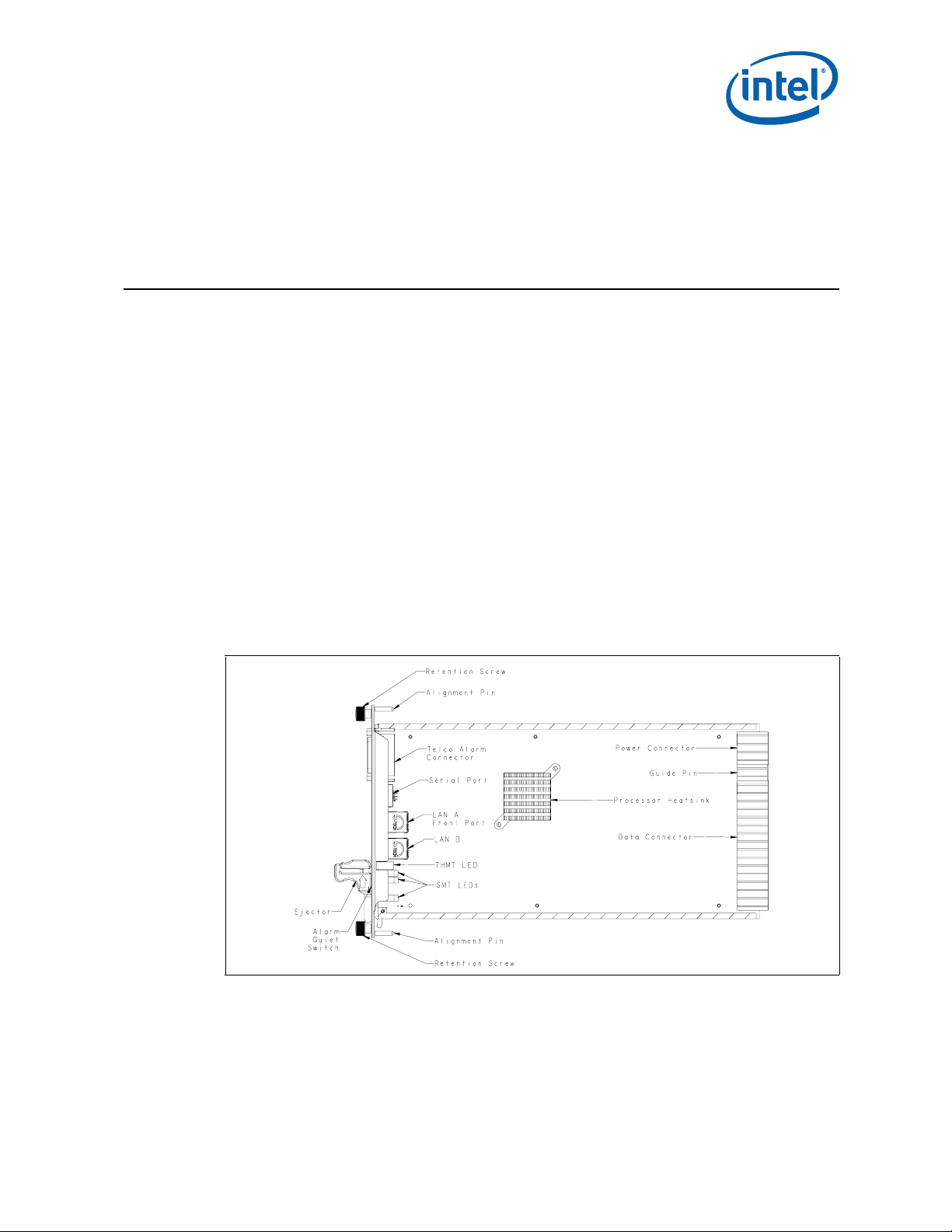
Figure 1. Top View of the Intel NetStructure
®
MPCMM0002 CMM
July 2007 Hardware TPS
Order Number: 309247-004US 13
Intel NetStructure® MPCMM0002 Chassis Management Module
Page 13

3.1.1 Quick Start
MPCMM0002 CMM—Getting Started
1. Open the packing material, find the packing list, and ensure that all the necessary
components are present for the Intel NetStructure
®
MPCMM0002 CMM.
2. Take the MPCMM0002 CMM to the chassis in which it will be installed.
3. Following standard ESD protection procedures, remove the CMM from its anti-static
bag.
4. Insert the management module into the card guides for the dedicated CMM slot.
Follow the chassis manufacturer’s or system vendor’s directions for the proper
orientation of the CMM.
5. As the CMM is being pushed into the slot, keep the ejector handle open until it
engages with the card guide. Ensure the alignment pins on the faceplate engage
the receptacles on the card cage. When the ejector handle engages, rotate the
ejector handle toward the faceplate until the card is fully seated.
6. Use a screwdriver or pair of pliers to tighten the retention screws on both ends of
the faceplate.
7. If the chassis power is on, the CMM will turn on automatically.
8. Connect the appropriate cables to the front or rear serial port, LAN ports. Connect
the telco alarm connector, if desired.
9. If a second CMM is to be installed in the chassis, follow the same instructions in this
procedure.
To remove the CMM:
1. Loosen the retention screws with a screw driver (Type#1 Philips head screw
driver).
2. Pull the ejector away from the faceplate (unlatch condition for ejector) enough to
ensure that the blue LED on the faceplate begins to flash. At this stage, the CMM
remains attached to the chassis (the backplane connector of CMM is still mated
with the chassis’s connector).
3. When the blue hot swap LED turns solid blue, pull the ejector farther out in order to
eject the CMM from the chassis.
Note: The hot swap LED will turn solid blue only when the redundancy feature is fully
enabled.
®
Intel NetStructure
Hardware TPS July 2007
14 Order Number: 309247-004US
MPCMM0002 Chassis Management Module
Page 14
Module Components—MPCMM0002 CMM
4.0 Module Components
4.1 Block Diagram
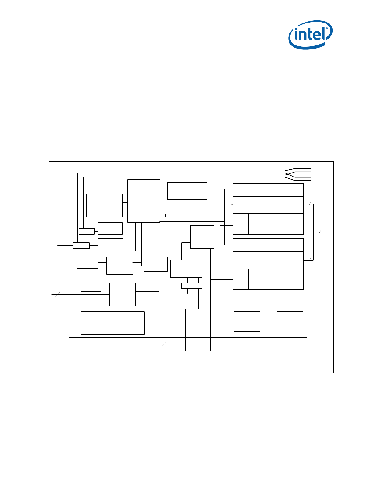
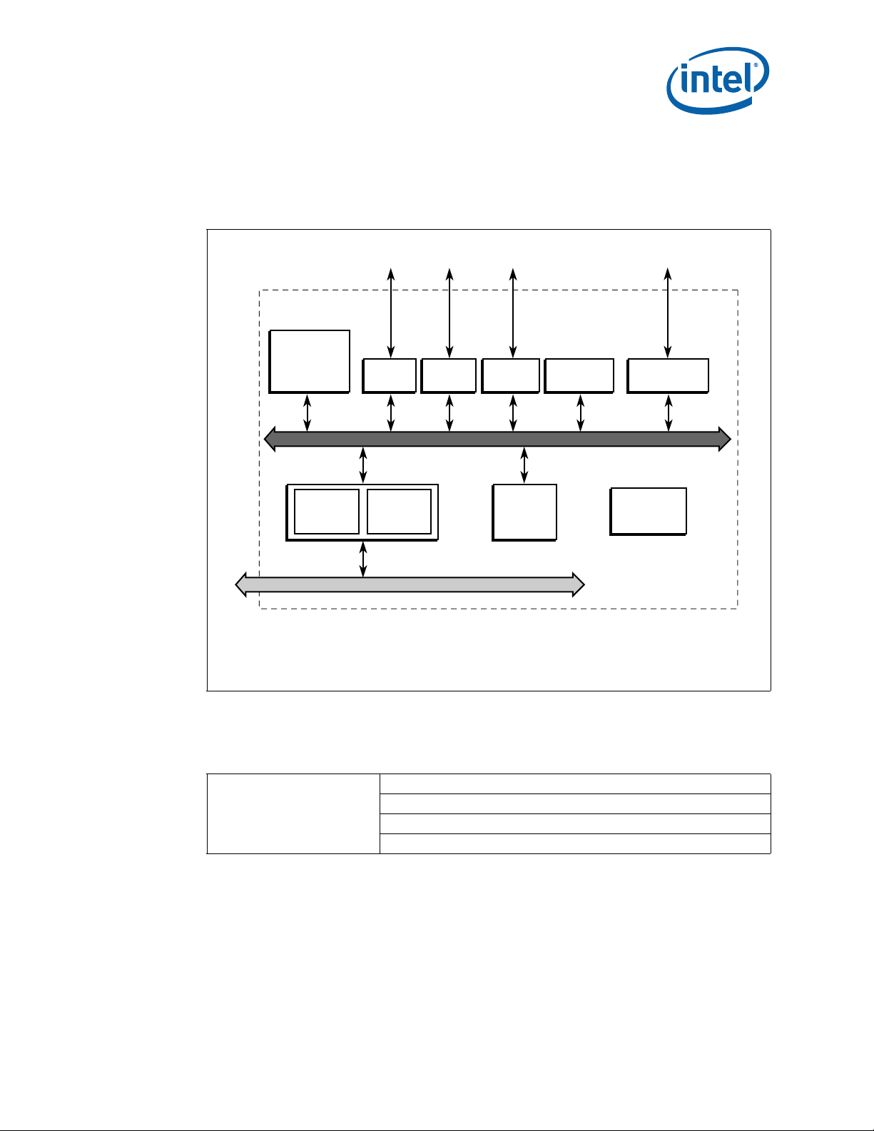
The block diagram for the Intel NetStructure® MPCMM0002 CMM is shown in Figure 2.
Figure 2. CMM Block Diagram
RJ45
RJ45
Alarm
Alarm
LEDs
3
Button
RS-232
Mux
Mux
Battery
Telco
Relays
SODIMM
Socket
128MB
10/100
NIC
10/100
NIC
RTC
-48VDC Power
Control
80321
Intel®
XScale™
Core
and IOP
w/ PCI
Bridge
I2C
ADM1026
GPIO
8/16/32/64 MB
flash
Latch
SIO Serial
Controller
Debug
LEDs
Debug
Drivers
CPLD
Control
Address
Decode
GPIO
Control
Address
Decode
GPIO
Clocks
OCS
FRU
Interrupt
router
FPGA 1
Interrupt
router
FPGA 2
I2C
Engines
I2C
Engines
Debug
RTM
BP
Switch
I2C[0:20]
42 I2C
I2C[21:41]
4
Health/
User
LEDs
July 2007 Hardware TPS
Order Number: 309247-004US 15
Fault
LED
Ejector
Blue LED
Intel NetStructure® MPCMM0002 Chassis Management Module
Page 15
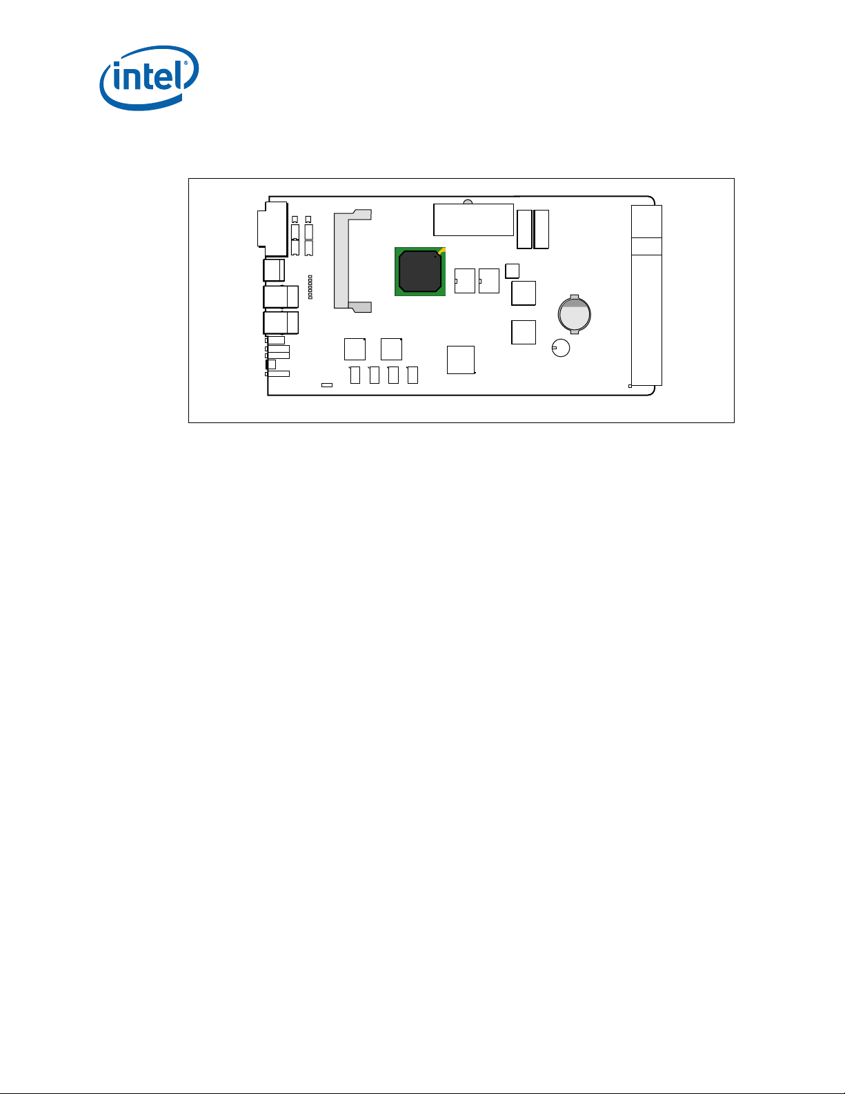
The major components of the CMM are arranged as shown in Figure 3.
Figure 3. CMM Top View Layout
MPCMM0002 CMM—Module Components
Telco
Serial
LAN B
LAN A
LED
Opto
Relay RAM
Debug
LED
NIC1
J3
NIC2
CPU
M
Power Brick
Flash
CPLD
+ +
S2 switch
FPGA
Bulk Cap
Battery
Super Cap
Power
Guide
Pin
Data
B5106-01
The PCB is composed of 10 layers of FR406 (or equivalent material). The outer layers
(1 and 10) are 0.5 ounce copper (plated to 1.6 ounces); all other layers are 1 ounce
copper.
Note: S2 abov e is a four-pole DIP switch block. The first switch in the DIP, S2-1 (1:8), is used
for password reset; the other three switches, S2-2, S2-3, and S2-4, are currently not
used. The default position for S2-1 is the ‘off’ position (open). See the Intel
NetStructure
®
MPCMM0001 Chassis Management Module and Intel NetStructure®
MPCMM0002 CMM Software Technical Product Specification for procedures on resetting
the CMM password.
®
Intel NetStructure
Hardware TPS July 2007
16 Order Number: 309247-004US
MPCMM0002 Chassis Management Module
Page 16
Module Components—MPCMM0002 CMM
Internal Bus
4.2 Intel® 80321 Processor
The CPU in the MPCMM0002 CMM is an Intel® 80321 Processor/PCI Application Bridge
with Intel
Figure 4. Intel
XScale® technology. The internal block diagram is shown in Figure 4.
®
80321 Processor Internal Block Diagram
2
C
I
Serial Bus
I2C Bus
Interface
Two
DMA
Channels
Application
Accelerator
Intel
Serial Bus
Serial Bus
Performance
Monitoring
Unit
®
80321 I/O Processor
®
Intel
XScale
Core
Messaging
Unit
72-Bit
I/F
®
DDR I/F
Unit
Address
Translation
Unit
64-bit / 32-bit PCI Bus
32-Bit
I/F
PBI Unit
(Flash)
SSP
Notes:
®
XScale® Microarchitecture is ARM* Architecture compliant.
Intel
* Other brands and names are the property of their respective owners.
B3063-01
This processor runs at 600 MHz and has an integrated chipset for lower power usage;
the typical power consumption of the CPU is 4 W. Other features are given in Table 2.
Table 2. Processor Features (Sheet 1 of 2)
ARM* V5T Instruction Set
Integrated Intel XScale® Core
July 2007 Hardware TPS
Order Number: 309247-004US 17
ARM V5E DSP Extensions
400 MHz and 600 MHz
Write Buffer, Write-back Cache
Intel NetStructure® MPCMM0002 Chassis Management Module
Page 17
Table 2. Processor Features (Sheet 2 of 2)
PCI Local Bus Specification, Rev. 2.2 compliant
PCI-X Addendum to the PCI Local Bus Specification, Rev. 1.0a
64-bit/66 MHz Operation in PCI Mode
PCI Bus Interface
Memory Controller
Address Translation Unit
DMA Controller
Application Accelerator Unit
2
I
C Bus Interface Units
SSP Serial Port
Peripheral Performance
Monitoring Unit
Timers
544-Ball, Plastic Ball Grid Array
(PBGA)
Eight General Purpose I/O Pins
64-bit/133 MHz Operation in PCI-X Mode
Support 32-bit PCI Initiators and Targets
Four Split Read Requests as Initiator
Eight Split Read Requests as Target
64-bit Addressing Support
PC200 Double Data Rate (DDR) SDRAM
Up to 1 GByte of 64-bit DDR SDRAM (128 MBytes on MPCMM0002)
Up to 512 MBytes of 32-bit DDR SDRAM
Single-bit Error Correction, Multi-bit Support (ECC)
1024 Byte Posted Memory Write Queue
40- and 72-bit wide Memory Interface
2 KByte or 4 KByte Outbound Read Queue
4 KByte Outbound Write Queue
4 KByte Inbound Read and Write Queue
Connects Internal Bus to PCI/PCI-X Bus
Two Independent Channels Connected to Internal Bus
Up to 1064 MByte/s Burst Support in PCI-X Mode
Up to 1600 MByte/s Burst Support for Internal Bus
Two 1 KB Queues in Ch-0 and Ch-1
232 Addressing Range on Internal Bus Interface
264 Addressing Range on PCI Interface
Performs XOR on Read Data
Compute Parity Across Local Memory Blocks
1 KByte/512 Byte Store Queue
Two Separate I
Serial Bus
Master/Slave Capabilities
System Management Funct ions
Full-duplex Synchronous Serial Interface
Supports 7.2 KHz to 1.84 MHz Bit Rates
One Dedicated Global Time Stamp Counter
Fourteen Programmable Event Counters
Three Control/Status Registers
Two Dual-programmable 32-bit Timers
Watchdog Timer
MPCMM0002 CMM—Module Components
2
C Units (one used on MPCMM0002)
®
Intel NetStructure
Hardware TPS July 2007
18 Order Number: 309247-004US
MPCMM0002 Chassis Management Module
Page 18

Module Components—MPCMM0002 CMM
4.3 Memory
The CMM has a SODIMM (Small Outline Dual Inline Memory Module) socket on board.
The SODIMM is populated with a 128 MByte unbuffered memory module.
The CMM also has four separate 16 MByte flash modules. These are Intel® E28F128
flash memory modules. Each memory module has multiple lockable regions within the
flash.
4.4 Ethernet
The CMM has two Intel® 82551QM Fast Ethernet Multifunction Controllers with
integrated media access controllers and physical interfaces. The output from each of
these chips is passed to a dedicated multiplexing device (mux), the SN74CBT16124.
Each mux can be individually controlled to send the Ethernet signals to one of three
destinations: the front panel, an optional RTM connection, or a separate backplane
connection. Separate magnetics (six total) provide magnetic coupling for the 10BASE- T
or 100BASE-TX signaling commonly associated with 10/100 MByte/s Ethernet.
In Figure 3, “CMM Top View Layout” on page 16, the four magnetics for the RTM and
backplane connections are at the bottom of the board. The two magnetics for the front
panel are integrated into the front panel RJ-45 connectors.
4.5 Serial Port UARTs
The UART (Universal Asynchronous Receiver/Transmitter) controller on the CMM board
is a T exas Instruments* TL16C752B dual UAR T chip. The first serial port is connected to
an RJ-45 connector on the front panel; the second serial port is passed to the rear of
the card for an optional RTM connection. Full modem hardware signals are passed
through to the RTM.
The UART driver provides 15 kV of ESD protection (8 kV contact, 15 kV air discharge).
July 2007 Hardware TPS
Order Number: 309247-004US 19
Intel NetStructure® MPCMM0002 Chassis Management Module
Page 19
4.6 FPGA
The MPCMM0002 CMM has two redundant field-programmable gate arrays (FPGAs) on
board. These two Xilinx* Spartan* II XC2S200 FPGAs have identical internal design,
but different addresses. A brief summary of the FPGA functions is shown in Table 3.
Table 3. FPGA Features
Signal Description
IPMI 1.5-compliant buses, pulled up to 3.3 V and operating at 100 kHz
IPMB
compatible
buses
Bus 50nS basic memory bus with data, address, chip select, output enable, and write enable
Interrupt
Router
20 IPMB ports per FPGA (40 total): 32 IPMBs for dual star routing to up to 16
AdvancedTCA* slots, 2 shared buses for PEMs and fan trays, 2 buses for communication
between CMMs, and 4 spare IPMBs for future expansion
2
One I
C port per FPGA (2 total) for communication to CDMs
The FPGA is responsible for identifying and routing interrupt requests from multiple sources
on the CMM, including the following: internal IPMB engine, other FPGA, both UARTs, the
ADM1026 controller, the CPLD, and both LAN controllers
4.7 Redundancy and Hot Swap CPLD
A Xilinx XC95144XL CPLD is used on the CMM to control the redundancy failover logic,
Hot Swap logic, FPGA control, and address decode for simple devices on the CMM. This
CPLD also contains the PCI arbitration circuitry for the 80321 processor and the
Ethernet controllers.
MPCMM0002 CMM—Module Components
4.8 Watchdog Timer
A Maxim* MAX6374KA-T watchdog timer is used to protect against CPU lockups. The
CMM firmware strobes the watchdog periodically; if the CPU fails to strobe the
watchdog within a given time interval, the watchdog sends a signal to the CPLD that
forces the CPU to reset. This allows the processor to automatically recover to a known
good state in the case of lockup.
Note: If the watchdog timer fires, the IPMB signals are not affected by the CPU timer reset.
The other CMM automatically takes over and manages the chassis.
4.9 Real-Time Clock
The CMM time-stamps certain events as they occur within the system, particularly
entries into the System Event Log (SEL). A Dallas Semiconductor* DS1307 real-time
clock provides this capability.
To avoid losing the current time, the CMM provides independent power to the DS1307
with an on-board battery (size CR2032). The battery provides approximately five years
of run time for the clock in case of a power failure or if the CMM is removed from a
chassis.
Batteries have limited shelf lives. After many years in storage, a battery may not be
able to hold a charge. To supplement the battery, a super capacitor (SCap) is also
provided on the CMM; this provides a mechanism to get up to two hours of backup
power for the clock in case of a power failure. Though the SCap will not hold a charge
for even a full day, the ability to power the clock circuit during a power failure even
after years in storage is a reliability feature of the CMM.
The battery and SCap are both diode-OR’d to ensure that either one can supply the
power for the clock without being affected by the other backup power source.
®
Intel NetStructure
Hardware TPS July 2007
20 Order Number: 309247-004US
MPCMM0002 Chassis Management Module
Page 20

Module Components—MPCMM0002 CMM
4.10 ADM1026 Controller
An Analog Devices* ADM1026 controller monitors the on-board voltages and manages
the thermal sensors. The processor communicates with the ADM1026 through an I
bus.
4.11 Hot Swap Controller
The CMM uses an LTC4250AH* Hot Swap controller to ramp voltages and watch for
over-current conditions. If the CMM draws more than 2.5 A for more than 500 µs, the
Hot Swap controller terminates.
The Hot Swap controller waits for the enable signals (short pins tied to each return) to
connect before ramping up the circuitry on the CMM. Similarly, if a CMM is pulled out of
the system, the Hot Swap controller immediately cuts power to the board.
4.12 Ride-Through Support
Many carriers require equipment to survive a 5 ms period without any power in order to
survive power glitches due to short circuit, power switchovers, etc. Section 4.1.4.3 of
the PICMG 3.0 specification requires boards to survive this 5 ms drop-out and
recommends that other chassis elements also have capability to ride through these
transients.
The MPCMM0002 CMM module meets this requirement. The CMM will survive the zero
volt transient described in Table 4-4 of the PICMG 3.0 specification. Large bulk
capacitors next to the DC-DC power converters provide this hold-up capacity.
4.13 IPMB Isolation Logic
2
C
In a carrier-grade system it is important to prevent cascaded failures; that is, a failure
in one element that affects other system elements and causes them to fail or lose
significant functionality . A shared bus is more sensitive to a single item impacting other
elements than a simple point-to-point system. This is one reason the MPCMM0002 CMM
chassis management module implements the hybrid dual IPMB star topology outlined in
Section 6.1, “IPMB Routing” on page 28.
Some IPMB channels are dedicated links between the CMMs and an individual blade;
this type of link is called a star. Some IPMB channels are shared among several devices,
and this type of link is called a bus. The star and bus elements have different isolation
logic in the CMM.
4.13.1 Dual Star IPMB Isolation
The dual star IPMBs on the MPCMM0002 CMM use MOSFET-controlled isolators to
disconnect all the radial IPMB signals automatically if power fails on a CMM. The
isolation circuit is pictured in Figure 5. The hardware ensures that the CMM is isolated
from the dual star IPMBs if power fails.
July 2007 Hardware TPS
Order Number: 309247-004US 21
Intel NetStructure® MPCMM0002 Chassis Management Module
Page 21
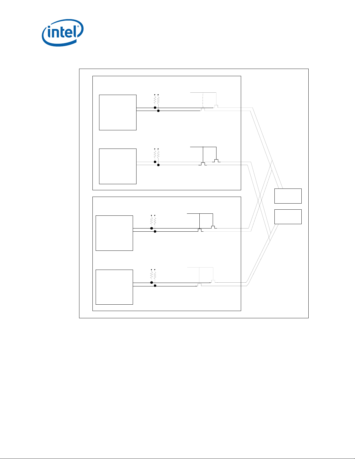
Figure 5. IPMB Dual Star Isolation
MPCMM0002 CMM—Module Components
CMM 1
FPGA 1
FPGA 2
CMM 2
FPGA 1
IPMBa
IPMBa
IPMBb
IPMBb
IPMB_ P W R
IPMB_ P W R
IPMB_ P W R
IPMB_PWRGOOD
IPMB_ P W RG O O D
IPMB_PW RG O OD
SLOT a
or
CDM a
SLOT b
or
CDM b
IPMB_ P W R
IPMB_ P W RGO OD
FPGA 2
IPMBb
IPMBb
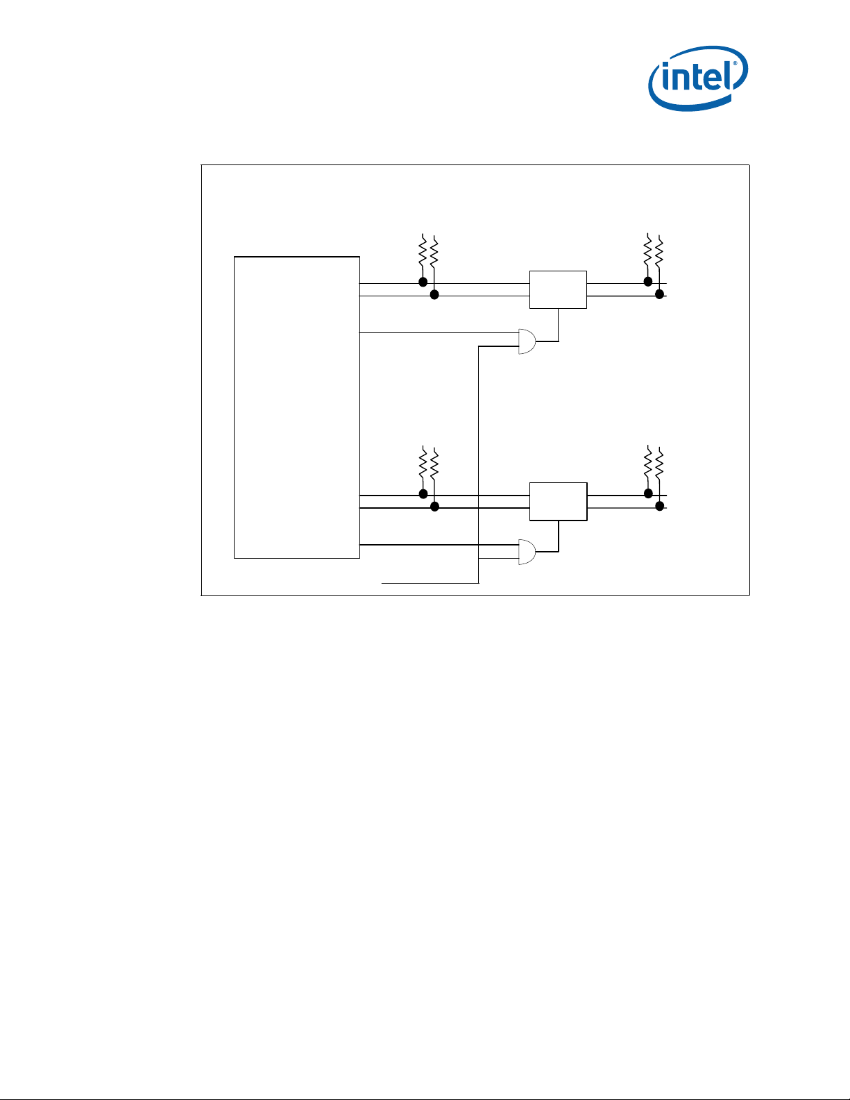
4.13.2 Dual Bus IPMB Isolation Requirements
The isolation requirements for a dual bus IPMB are more stringent. In addition to the
power failure isolation needed by radial IPMBs, dual bus IPMBs must be able to
selectively enable and disable the is olation on each bus. Furtherm ore, each element on
the bus must protect against errors that can cause the bus to hang. Finally, there are
electrical drive and rise time requirements that are more difficult to meet on a shared
bus.
An LTC4300 on each bus provides the necessary individually selectable isolation
mechanisms in addition to rise time acceleration. A watchdog timer is also used to
ensure the bus is isolated if the CPU locks up and resets so that glitches are not
propagated to other controllers on the bus. See Figure 6.
®
Intel NetStructure
Hardware TPS July 2007
22 Order Number: 309247-004US
MPCMM0002 Chassis Management Module
Page 22
Module Components—MPCMM0002 CMM
Figure 6. Dual Bus IPMB Isolation
FPGA 2
IPMBa
GPIO_0
IPMBb
GPIO_1
IPMB _PWR
INHIB ITa#
IPMB _PWR
INHIB ITb#
WDT
Local
Local
LTC4300A
ENA
LTC4300A
ENA
Local
IPMB_PWR
IPMB a to
Back p lan e
Local
IPMB_PWR
IPMBb
to
Back p lan e
July 2007 Hardware TPS
Order Number: 309247-004US 23
Intel NetStructure® MPCMM0002 Chassis Management Module
Page 23

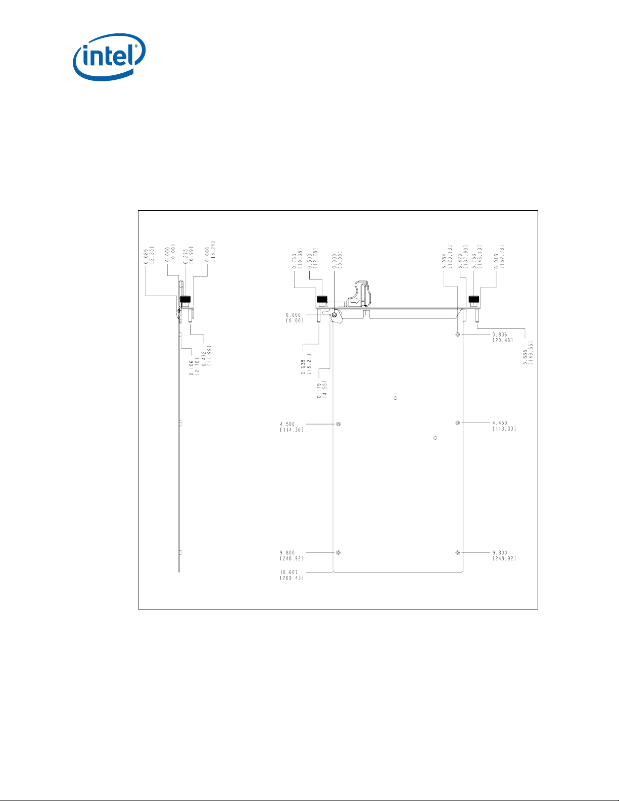
5.0 Mechanical Information
5.1 Dimensions
Dimensions for the CMM are shown in Figure 7. The origin is in the lower right corner.
All dimensions are shown in millimeters.
The form factor of the CMM PCB has a height of 144.4 mm and a depth of 282.5 mm.
The faceplate has a horizontal slot pitch (width) of 3 HP (0.6 inches).
Dimensions for the CMM backing plate are shown in Figure 8. The origin for these
Figure 7. CMM Component Side 1 Dimensions
dimensions is based on the mounting hole in the upper left corner.
MPCMM0002 CMM—Mechanical Information
®
Intel NetStructure
Hardware TPS July 2007
24 Order Number: 309247-004US
MPCMM0002 Chassis Management Module
Page 24
Mechanical Information—MPCMM0002 CMM
Figure 8. CMM Backing Plate Dimensions
July 2007 Hardware TPS
Order Number: 309247-004US 25
Intel NetStructure® MPCMM0002 Chassis Management Module
Page 25
The gasket is on the secondary side of the backing plate and extends over the pitch
line, just as PICMG 3.0 boards extend their gasket over the pitch line. The outer face of
the backing plate is 0.15 mm (0.0059 inches) inside the nearest pitch line. Since the
gasket has a nominal compressed size of 1.53 mm (0.0602 inches) and a four-sigma
range of 0.99 mm (0.0390 inches) to 2.07 mm (0.0815 inches), the gasket must seal
on a surface that is between 0.84 mm (0.0331 inches) and 1.92 mm (0.0756 inches)
from the left side pitch line.
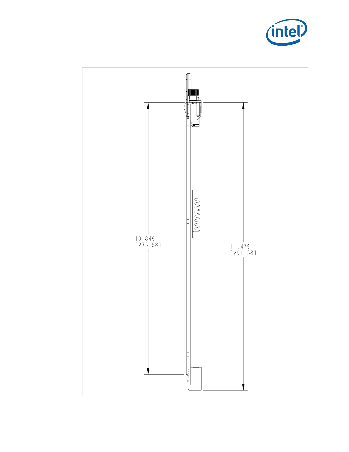
Figure 9. CMM Side View Dimensions
MPCMM0002 CMM—Mechanical Information
5.2 Front Panel Hardware
Table 18, “Telco Alarm Pinout” on page 49 shows two retention screws and two
alignment posts on the MPCMM0002 CMM faceplate. Like the hardware used with
PICMG* 3.0 boards, these items are M3 hardware. However, since the 15.24 mm (0.6
inches) pitch of the CMM does not allow sufficient room to put the retention screws and
alignment posts side by side, the alignment posts are offset slightly.
®
Intel NetStructure
Hardware TPS July 2007
26 Order Number: 309247-004US
MPCMM0002 Chassis Management Module
Page 26
Mechanical Information—MPCMM0002 CMM
There is only one ejector on the CMM, but it matches the subrack interface geometry
defined in Section 2.2.7 of the PICMG 3.0 specification. Note, however, that the ejector
handle is 2 mm (0.0787 inches) thick, not the 2.5 mm (0.0984 inches) thickness that
many PICMG 3.0 boards use.
A switch on Component Side 2 of the PCB detects the opening and closing of the ejector
handle.
5.3 Rear Connector Placement
5.3.1 MPCMM0002 CMM Rear Connectors
The CMM uses three connectors (for power, data, and a guide pin) that can mate with
either vertical (backplane) connectors or coplanar connectors. The power connector is
an FCI* 85719-107LF (or equivalent) connector. As shown in Table 14, “CMM Power
Connector” on page 32, the A1 pin on the connector is located at coordinates (2.37,
96.34). The data connector is an FCI 89095-102LF (or equivalent). Pin 1 on the data
connector is located at coordinates (13.7, 64.65). The guide pin connector is an FCI
73474-201 (or equivalent).
5.3.2 Coplanar Mating Connectors
In a coplanar mating arrangement, a FCI* HM1L54LDP000H6P connector with FCI*
72019-101 guide pin is mated to the data connector on the CMM, while a FCI*
HM1L52LDP493H6P (or equivalent) connector mates with the power connector.
5.3.3 Vertical Mating Connectors
When a CMM board mates directly into a backplane, vertical mating connectors are
used. The data connector that mates to the CMM is a FCI* 89009-116 with FCI*
70295-001 guide pin and 73475-101 shroud, while the power connector is an FCI*
HM1W52ZPR493H6P (or equivalent). Since they are mounted on a backplane, the rear
of these two connectors must be in the same plane.
Example: If mounted horizontally with Component Side 1 up, the bottom row of holes
for the data connector is 1.775 mm (0.0699 inches) lower than the power connector.
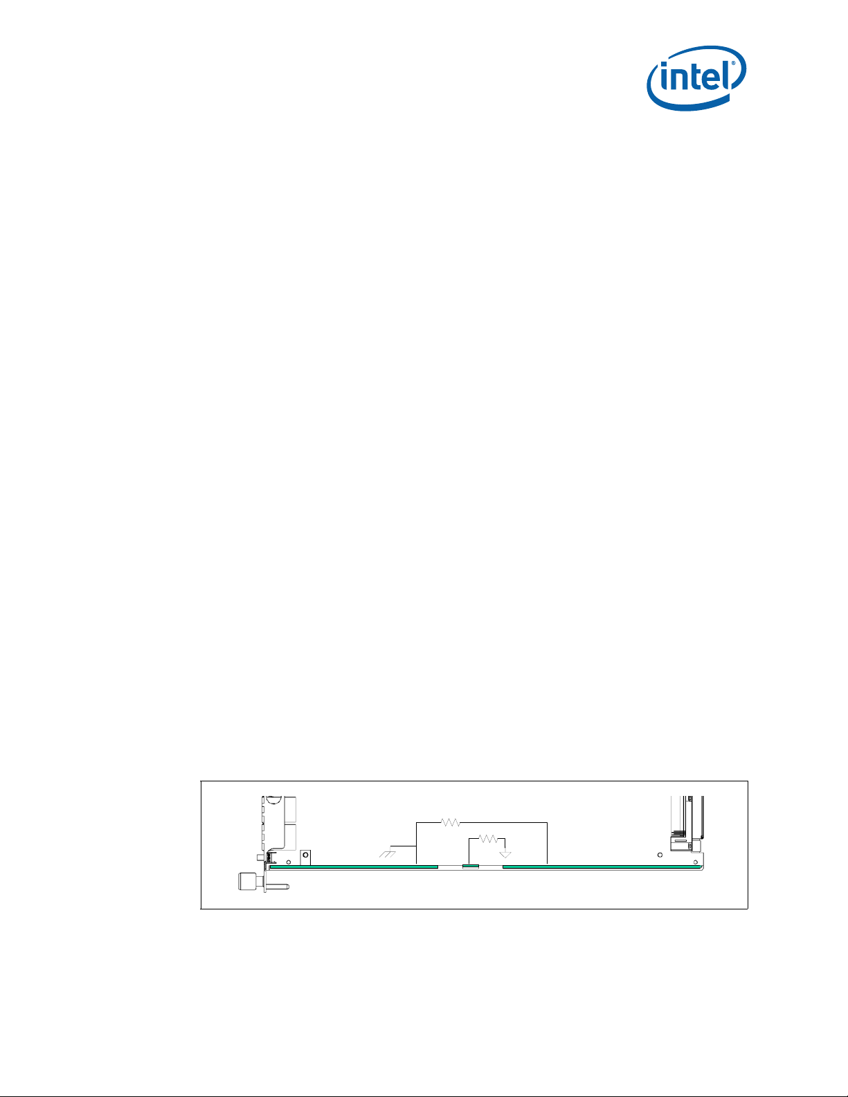
5.4 ESD Discharge Strip
The ESD strip along the bottom of the CMM follows the guidelines in Section 2.2.5 of
the PICMG* 3.0 specification. The electrical definition of the ESD discharge strip is
shown below.
Figure 10. CMM ESD Strip Electrical Definition
Dimensions of the ESD strips are shown in Table 16, “Ethernet Port Pinouts” on
page 47.
10MΩ
10MΩ
July 2007 Hardware TPS
Order Number: 309247-004US 27
Intel NetStructure® MPCMM0002 Chassis Management Module
Page 27

6.0 Backplane Considerations
6.1 IPMB Routing
The Intel NetStructure® MPCMM0002 CMM is designed to support a hybrid dual IPMB
star topology.
The CMMs can support up to 16 slots, the maximum number of boards in a PICMG* 3.0
chassis. Each board in the subrack has two dedicated IPMBs going to it. Each IPMB is
arranged in a ‘Y’ pattern: the connection from the board is split to two legs, one going
to each CMM. Each CMM is present on both buses to each board. In addition, there are
two shared IPMB buses routed between the CMMs for private, dedicated IPMB traffic
between the two CMMs. While the CMMs theoretically can talk between themselves
over any of 30+ IPMBs, the private IPMB traffic between CMMs is normally over these
two inter-CMM links.
MPCMM0002 CMM—Backplane Considerations
Note: A shared dual IPMB bus is used for chassis elements such as PEMs and one or more fan
trays. This shared dual bus allows the CMM to support varying numbers of PEMs, fan
trays, and other intelligent chassis elements.
In compliance with the PICMG 3.0 specification, the shared bus IPMB signals have an
isolating buffer device (LTC4300) to ensure proper bus isolation in a shared bus
environment. The radial (star) IPMB connections to each node are not required to have
this same isolation circuitry since each node is effectively isolated already by the star
topology.
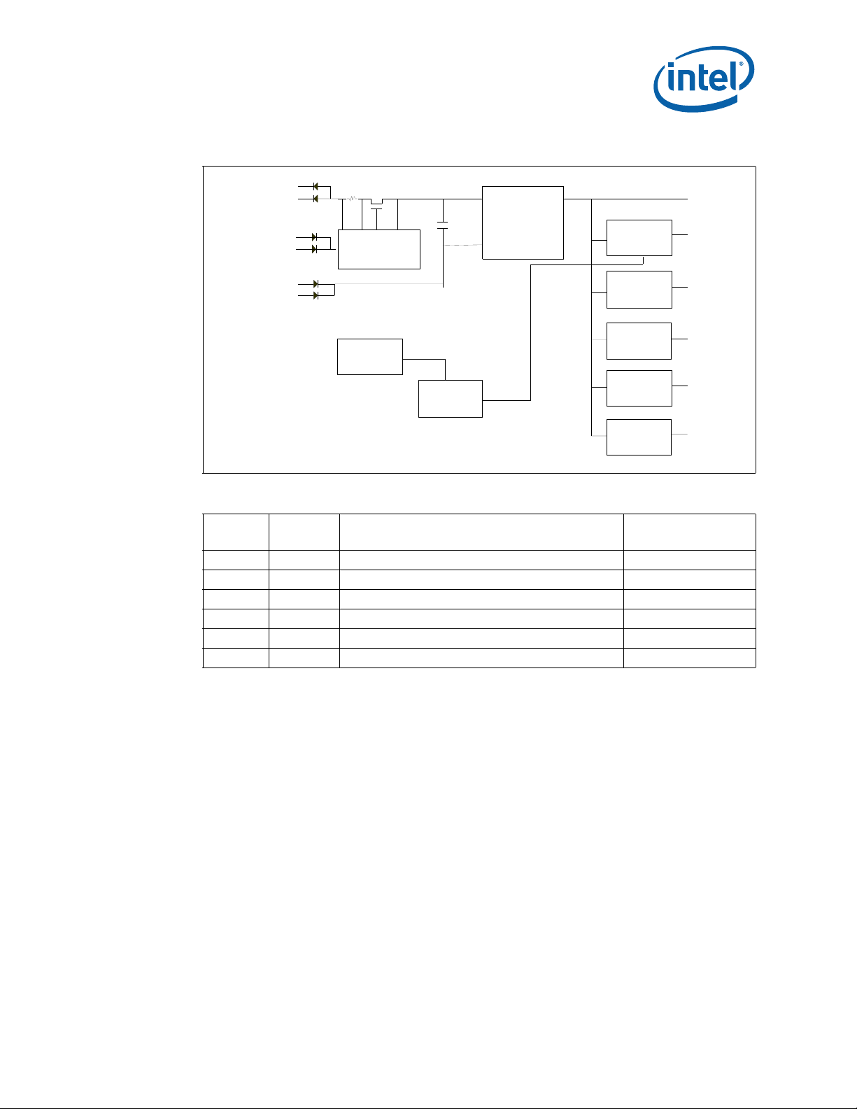
6.2 CMM Power
6.2.1 DC Power Input
Each CMM receives dual -48 VDC power feeds on its power connector. Since the
maximum power draw is 28 W, the maximum power draw from each CMM is less than 1
A. The typical power draw for each CMM is 17 W. Most of the power is derived from the
3.3 V converter.
®
Intel NetStructure
Hardware TPS July 2007
28 Order Number: 309247-004US
MPCMM0002 Chassis Management Module
Page 28
Backplane Considerations—MPCMM0002 CMM
Figure 11. Power System Block Diagram
-48V
Power
Enable
(MLBF)
-48V Return
Table 4. Voltage Usage
Voltage
12 V 0.3 A Op Amp and IPMB isolation circuit ADM1026
5 V 1 A Misc components that cannot use 3.3 V ADM1026
3.3 V 4 A Most logic ADM1026
2.5 V 5 A Memory interface ADM1026
1.3 V 3 A IOP321 core ADM1026
1.25 V 1 A DDR Termination ADM1026
Current
Max
Hotswap
Controller
ADM1026
Filter
Cap
-48 V t o
3.3V
Power
Bri ck
LT1371
LT1930
PG33
CPLD
PG5
TPS54610
TPS54610
Discrete
Linear
Regulator
Where Used Monitored By
3.3V
5V
12V
2.5V
1.3V
1.25V
The CMM supports an input voltage range of –34 VDC to –72 VDC. However, the 5 ms
ride-through capability (see Section 4.12, “Ride-Through Support” on page 21)
assumes a prior minimum voltage of –43 VDC.
6.2.2 CDM Power
The CMM provides a few powered outputs that chassis designers can use as they see
fit. The chassis data modules (sometimes called shelf FRUs) are described in more
detail in Section 8.0, “Chassis Data Modules (CDMs)” on page 43. Each CMM provides a
diode-OR’d 5 V output at 50 mA maximum current to the CDMs. Chassis designers can
use this 5 V output to power simple EEPROMs in a CDM. The CMMs can both drive a
tricolor LED on the CDM as well.
July 2007 Hardware TPS
Order Number: 309247-004US 29
Intel NetStructure® MPCMM0002 Chassis Management Module
Page 29

Figure 12. CDM Power Input
6.2.3 Filter Tray
The CMM also provides direct support for a filter tray. The CMM provides signals to
handle a filter presence switch, two thermistors, and a tricolor LED.
MPCMM0002 CMM—Backplane Considerations
CDM 1 CDM 2
The filter presence switch is typically a mechanical switch that connects the AF_PRES#
signal to ground when an air filter is installed in the chassis. The switch is debounced in
software.
The two thermistor inputs provide redundant temperature readings to the CMM. The
thermistors should be a NTC (negative thermocouple) device like the US Sensor*
USX2257 thermocouple (http://www.ussensor.com/). For maximum accuracy, a
dedicated logic ground reference signal AFTREF is provided to isolate localized
perturbations to logic ground. Chassis designers should use the AFTREF signal
exclusively for these thermocouples and should route the two temperature signals and
the reference signal in close proximity.
6.2.4 Power Switch
The CMM has support for an optional soft power switch. This dual-pole input signal can
be used to signal the CMM to gracefully shut down the elements within the chassis.
Both poles of this switch are debounced in software. If only one contact on the switch
closes, the CMM flags this as an error and generates a system event log entry.
These direct drive capabilities of the CMM are summarized in the table below. All the
outputs are protected via OR-ing diodes, as shown in Figure 12.
®
Intel NetStructure
Hardware TPS July 2007
30 Order Number: 309247-004US
MPCMM0002 Chassis Management Module
Page 30

Backplane Considerations—MPCMM0002 CMM
Table 5. Chassis Elements Directly Driven by CMM Hardware
Chassis
Element
CDM
Filter Tray
Power switch Dual pole switch Soft power switch to CMMs
LAN ports 2 LEDs each (4 total) Speed on one LED, Link and Activity on the other
Component Notes
EEPROM + others
LED Tricolor LEDs driven by CMM
2 Thermistors NTC sensors, such as US Sensor USX2257
LED Red plus green LEDs driven by CMM
6.2.5 Ethernet Routing
Each CMM provides two Ethernet channels that can be routed to the base interface of
PICMG* 3.0 hub slots. The PICMG 3.0 specification only allocates space for one ShMC
slot, but the backplane can typically be set up to “poach” an unused slot in order to
provide a connectivity option.
A 14-slot chassis typically uses 14 base interface channels (13 for other slots plus one
for the ShMC). However, the specification defines 16 total channels for the base
interface. The second port from each CMM can be routed to an unused upper channel of
the opposite hub or fabric board.
Figure 13. Ethernet Port Poaching
50 mA @ 5 V max; typically uses series resistance to drop
voltage to 3.3.V.
CMM 1
LAN A LAN B
Ethernet
Fabric A
Port 0
Port 1
...
Port 14
Port 15
CMM 2
LAN A LAN B
Ethernet
Fabric B
Port 0
Port 1
...
Port 14
Port 15
July 2007 Hardware TPS
Order Number: 309247-004US 31
Intel NetStructure® MPCMM0002 Chassis Management Module
Page 31

7.0 Rear Connections
7.1 CMM Connector Pinouts
Each CMM has a power connector and a data connector.
7.1.1 CMM Power Connector
The CMM power connectors are standard J12 power receptacles as shown in Figure 14.
Figure 14. CMM Power Connector
12
MPCMM0002 CMM—Rear Connections
1
E
A
®
Intel NetStructure
Hardware TPS July 2007
32 Order Number: 309247-004US
MPCMM0002 Chassis Management Module
Page 32

Rear Connections—MPCMM0002 CMM
The pinout of each CMM power connector is shown in Table 6.
Table 6. Power Connector Pinouts
Pin Signal Purpose Pin Length
B12, D12 SGND Shelf ground, mostly for safety Long
A5, C5, E5 GND Logic ground for signal returns Long
C1, E1 -48 V_A A power feed Medium
B2, D2 -48 V_B B power feed Medium
C3, E3 -48 VRTNA Return path for A feed Medium
B4, D4 -48 VRTNB Return path for B feed Medium
A1 -48VRTN_A_MLBF
A3 -48VRTN_B_MLBF
D6 PWRALRM_NO Power alarm relay, normally open Medium
E9 MNRALRM_COM Minor alarm relay, common path Medium
C9 MJRALRM_COM Major alarm relay, common path Medium
A9 CRTALRM_COM Critical alarm relay, common path Medium
B6 PWRALRM_COM Power alarm relay, common path Medium
E7 MNRALRM_NO Minor alarm relay, normally open Medium
C7 MJRALRM_NO Major alarm relay, normally open Medium
A7 CRTALRM_NO Critical alarm relay, normally open Medium
E11 MNRALRM_NC Minor alarm relay, normally closed Medium
C11 MJRALRM_NC Major alarm relay, normally closed Medium
A11 CRTALRM_NC Critical alarm relay, normally closed Medium
D10 MNRRES+ Minor alarm reset, positive polarity Medium
B10 MNRRES- Minor alarm reset, negative polarity Medium
D8 MJRRES+ Major alarm reset, positive polarity Medium
B8 MJRRES- Major alarm reset, negative polarity Medium
Return path for A feed (mate last, break first pin)
that allows Hot Swap controller to turn system
power on and off
Return path for B feed (mate last, break first pin)
that allows Hot Swap controller to turn system
power on and off
Short
Short
July 2007 Hardware TPS
Order Number: 309247-004US 33
Intel NetStructure® MPCMM0002 Chassis Management Module
Page 33

Table 7 labels the pins on the power connector at the intersection of each row (A-E) and
column (1-12).
Table 7. Power Connector Pinouts Matrix
MPCMM0002 CMM—Rear Connections
1 -48V_A -48V_A -48_A_RTN_MLBF
2 -48V_B -48V_B
3 -48_A_RTN -48_A_RTN -48_B_RTN_MLBF
4 -48_B_RTN -48_B_RTN
5 GND GND GND
6 PWRALRM_NO PWRALRM_COM
7 MNR_NO MJR_NO CRT_NO
8 MJR+ MJR-
9 MNR_COM MJR_COM CRT_COM
10 MNR+ MNR-
11 MNR_NC MJR_NC CRT_NC
12 SGND SGND
Table 8 shows the staging of the power connector pins. Table 9 and Table 10 (for the
receptacle and for the header) show the physical locations of the pins identified by pin
code.
Table 8. Pin Staging
ED C B A
Order
First Mate 8 mm 4.3mm 19
Second Mate 7.25 mm 4.3mm 4
Third Mate 6.5 mm 4.3mm 3
Fourth Mate 5.75 mm 4.3mm 2
Last Mate 5 mm 4.3mm 1
Empty
Mating
Length
Tail
Length
Pin Code
Table 9. Power Connector Receptacle Pin Placement (Sheet 1 of 2)
1 4 4 1
2 3 3
3 4 4 1
4 3 3
®
Intel NetStructure
Hardware TPS July 2007
34 Order Number: 309247-004US
MPCMM0002 Chassis Management Module
ED C B A
Page 34

Rear Connections—MPCMM0002 CMM
Table 9. Power Connector Receptacle Pin Placement (Sheet 2 of 2)
5 4 4 4
6 2 2
7 2 2 2
8 2 2
9 22 2
10 2 2
11 2 2 2
12 19 19
ED C B A
Table 10. Power Connector Header Pin Placement
1 1 4 4
2 3 3
3 1 4 4
4 3 3
AB C D E
5 4 4 4
6 2 2
7 2 2 2
8 2 2
9 22 2
10 2 2
11 2 2 2
12 19 19
July 2007 Hardware TPS
Order Number: 309247-004US 35
Intel NetStructure® MPCMM0002 Chassis Management Module
Page 35

7.1.2 CMM Data Connector
The CMM data connector is a J16 signal connector. See Figure 15.
Figure 15. CMM Data Connector
48
A
MPCMM0002 CMM—Rear Connections
1
E
A
®
Intel NetStructure
Hardware TPS July 2007
36 Order Number: 309247-004US
MPCMM0002 Chassis Management Module
Page 36

Rear Connections—MPCMM0002 CMM
The pinouts for the data connector are shown in Table 11.
Table 11. Data Connector Pinouts (Sheet 1 of 2)
Signal Name Count Type Description Pin Name From Table 12
BP_AFT1 1 I Filter tray ambient temperature thermistor A E16
BP_AFT2 1 I Filter tray ambient temperature thermistor B E17
BP_AFTREF 1 I Filter tray ambient temperature thermistor return E18
BP_AFLED[1:2] 2 O
BP_AFPRES# 1 I
RP_ENET1_LNK# 1 O Ethernet port 1 to RTM Link LED drive A29
RP_ENET1_ACT# 1 O Ethernet port 1 to RTM Activity LED drive A30
RP_ENET1_SPD# 1 O Ethernet port 1 to RTM speed indicator A31
RP_ENET2_LNK# 1 O Ethernet port 2 to RTM Link LED drive B29
RP_ENET2_ACT# 1 O Ethernet port 2 to RTM Activity LED drive B30
RP_ENET2_SPD# 1 O Ethernet port 2 to RTM speed indicator B31
FRU0_STATUS[0:1] 1 O
FRU1_STATUS[0:1] 1 O
PWRSW[1:2] 2 I
BP_N_SCL[0..15]A and B 32 OD Node IPMB clock A2-A17, C2-C17
BP_N_SDA[0..15]A and B 32 OD Node IPMB data B2-B17, D2-D17
BP_CF_SCL_A and B 2 OD Chassis FRU IPMB clock A18, C18
BP_CF_SDA_A and B 2 OD Chassis FRU IPMB data B18, D18
BP_SH_SCL_A and B 2 OD Shared Bus IPMB clock A19, C19
BP_SH_SDA_A and B 2 OD Shared Bus IPMB data B19, D19
BP_RED_SCL_A and B 2 OD Redundant CMM IPMB serial clock A20, C20
BP_RED_SDA_A and B 2 OD Redundant CMM IPMB serial data B20, D20
BP_RP_SCL_A and B 2 OD Reserved IPMB clocks for RTM A21, C21
BP_RP_SDA_A and B 2 OD Reserved IPMB data for RTM B21, D21
BP_SP_SCL_A and B 2 OD RESERVED FOR FUTURE USE A22, C22
BP_SP_SDA_A and B 2 OD RESERVED FOR FUTURE USE B22, D22
BP_ENET1_TX0(+-) 2 I/O Ethernet port 1 to RTM A33, B33
BP_ENET1_RX0(+-) 2 I/O Ethernet port 1 from RTM A35, B35
BP_ENET2_TX0(+-) 2 I/O Ethernet port 2 to RMT A37, B37
BP_ENET2_RX0(+-) 2 I/O Ethernet port 2 from RTM A39, B39
BP_ENET1_TX1(+-) 2 I/O Reserved for GbE to RTM D33, E33
BP_ENET1_RX1(+-) 2 I/O Reserved for GbE from RTM D35, E35
BP_ENET2_TX1(+-) 2 I/O Reserved for GbE to RTM D37, E37
BP_ENET2_RX1(+-) 2 I/O Reserved for GbE from RTM D39, E39
Filter tray status tri-color LED control. Bit 1
controls the red LED. Bit 2 controls th e green LED .
Filter tray presence. This signal is pulled up to
+3.3V and is de-bounced by software.
Control signals for ShFRU status tri-color LED 1.
Bit 0 controls the red LED. Bit 1 controls the green
LED.
Control signals for ShFRU status tri-color LED 2.
Bit 0 controls the red LED. Bit 1 controls the green
LED.
Power switch input A or B from system power on/
off switch. These two signals have to be
debounced by software.
E19, E20
E21
D30, D31
C30, C31
E30, E31
July 2007 Hardware TPS
Order Number: 309247-004US 37
Intel NetStructure® MPCMM0002 Chassis Management Module
Page 37

MPCMM0002 CMM—Rear Connections
Table 11. Data Connector Pinouts (Sheet 2 of 2)
Signal Name Count Type Description Pin Name From Table 12
CFG_STX 1 O Serial transmit A28
CFG_SRX 1 I Serial receive D28
CFG_SCTS 1 I Serial clear to send E28
CFG_SRTS 1 O Serial request to send C28
CFG_SDSR 1 I Serial data set ready E29
CFG_SDTR 1 O Serial data terminal ready B28
BP_CMC_TX0(+-) 2 I/O Ethernet port 0 to switch A41, B41
BP_CMC_RX0(+-) 2 I/O Ethernet port 0 from switch A43, B43
BP_CMCX_TX0(+-) 2 I/O Ethernet port 1 to switch A45, B45
BP_CMCX_RX0(+-) 2 I/O Ethernet port 1 from switch A 47, B47
BP_CMC_TX1(+-) 2 I/O Reserved for GbE to switch D41, E41
BP_CMC_RX1(+-) 2 I/O Reserved for GbE from switch D43, E43
BP_CMCX_TX1(+-) 2 I/O Reserved for GbE to switch D45, E45
BP_CMCX_RX1(+-) 2 I/O Reserved for GbE from switch D47, E47
BP_NGO 1 O Negotiate output to other CMM E14
BP_NGOI 1 I Negotiate input from other CMM E15
BP_HLY# 1 O Healthy output to other CMM E12
BP_HLYI# 1 I Healthy input from other CMM E13
BP_PRESI# 1 I Other CMM is present (0V) E11
BP_PRES# 1 O Tie to ground E10
GA[0:7] 8 I Hardware Address E2-E9
A1-E1, A23-C23, A32-E32,
GND 61 I Ground
FRU_VCCA and B 2 I
RESV[1:11] 11 Reserved A26-E26, A27-E27, D23
GPIO[1:10] 10 I General Purpose Input Only A24-E24, A25-E25
BP_CMM_RESET# 1 O Inter CMM reset output to another CMM C29
BP_CMM_RESETI# 1 I Inter CMM reset input from another CMM D29
Power to CDMs (shelf FRUs) and distribution
board
C33, A34-E34, C35, A36-E36,
C37, A38-E38, C39, A40-E40,
C41, A42-E42, C43, A44-E44,
C45, A46-E46, C47, A48-E48
E22, E23
Table 12 identifies each pin on the data connector at the intersection of each row (A-E)
and column (1-48).
Table 12. Data Connector Pinouts Matrix (Sheet 1 of 3)
ED CBA
1 GND GND GND GND GND
2 GA0 BP_N_SDA_[1]_B BP_N_SCL_[1]_B BP_N_SDA_[1]_A BP_N_SCL_[1]_A
3 GA1 BP_N_SDA_[2]_B BP_N_SCL_[2]_B BP_N_SDA_[2]_A BP_N_SCL_[2]_A
4 GA2 BP_N_SDA_[3]_B BP_N_SCL_[3]_B BP_N_SDA_[3]_A BP_N_SCL_[3]_A
®
Intel NetStructure
Hardware TPS July 2007
38 Order Number: 309247-004US
MPCMM0002 Chassis Management Module
Page 38

Rear Connections—MPCMM0002 CMM
Table 12. Data Connector Pinouts Matrix (Sheet 2 of 3)
ED CBA
5 GA3 BP_N_SDA_[4]_B BP_N_SCL_[4]_B BP_N_SDA_[4]_A BP_N_SCL_[4]_A
6 GA4 BP_N_SDA_[5]_B BP_N_SCL_[5]_B BP_N_SDA_[5]_A BP_N_SCL_[5]_A
7 GA5 BP_N_SDA_[6]_B BP_N_SCL_[6]_B BP_N_SDA_[6]_A BP_N_SCL_[6]_A
8 GA6 BP_N_SDA_[7]_B BP_N_SCL_[7]_B BP_N_SDA_[7]_A BP_N_SCL_[7]_A
9 GA7 BP_N_SDA_[8]_B BP_N_SCL_[8]_B BP_N_SDA_[8]_A BP_N_SCL_[8]_A
10 BP_PRES# BP_N_SDA_[9]_B BP_N_SCL_[9]_B BP_N_SDA_[9]_A BP_N_SCL_[9]_A
11 BP_PRESI# BP_N_SDA_[10]_B BP_N_SCL_[10]_B BP_N_SDA_[10]_A BP_N_SCL_[10]_A
12 BP_HLY# BP_N_SDA_[11]_B BP_N_SCL_[11]_B BP_N_SDA_[11]_A BP_N_SCL_[11]_A
13 BP_HLYI# BP_N_SDA_[12]_B BP_N_SCL_[12]_B BP_N_SDA_[12]_A BP_N_SCL_[12]_A
14 BP_NGO BP_N_SDA_[13]_B BP_N_SCL_[13]_B BP_N_SDA_[13]_A BP_N_SCL_[13]_A
15 BP_NGOI BP_N_SDA_[14]_B BP_N_SCL_[14]_B BP_N_SDA_[14]_A BP_N_SCL_[14]_A
16 BP_AFT1 BP_N_SDA_[15]_B BP_N_SCL_[15]_B BP_N_SDA_[15]_A BP_N_SCL_[15]_A
17 BP_AFT2 BP_N_SDA_[16]_B BP_N_SCL_[16]_B BP_N_SDA_[16]_A BP_N_SCL_[16]_A
18 BP_AFTREF# BP_CF_SDA_B BP_CF_SCL_B BP_CF_SDA_A BP_CF_SCL_A
19 BP_AFLED1 BP_SH_SDA_B BP_SH_SCL_B BP_SH_SDA_A BP_SH_SCL_A
20 BP_AFLED2 BP_RED_SDA_B BP_RED_SCL_B BP_RED_SDA_A BP_RED_SCL_A
21 BP_AFPRES BP_RP _SDA_B BP_RP_SCL_B BP_RP_SDA_A BP_RP_SCL_A
22 FRU_VCCA BP_SP_SDA_B BP_SP_SCL_B BP_SP_SDA_A B P_SP_SCL_A
23 FRU_VCCB Reserved for future use GND GND GND
24 GPIO5 GPIO4 GPIO3 GPIO2 GPIO1
25 GPIO10 GPIO9 GPIO8 GPIO7 GPIO6
26 RESV5 RESV4 RESV3 RESV2 RESV1
27 RESV10 RESV9 RESV8 RESV7 RESV6
28 CFG_SCTS CFG_SRX CFG_SRTS CFG_SDTR CFG_STX
29 CFG_SDSR BP_CMM_RESETI# BP_CMM_RESET# RP_ENET2_LNK# RP_ENET1_LNK#
30 BP_PWRSW1 BP_FRU0_STATUS0 BP_FRU1_STATUS0 RP_ENET2_ACT# RP_ENET1_ACT#
31 BP_PWRSW2 BP_FRU0_STATUS1 BP_FRU1_STATUS1 RP_ENET2_SPD# RP_ENET1_SPD#
32 GND GND GND GND GND
33 RP_ENET1_TX1- RP_ENET1_TX1+ GND RP_ENET1_TX0- RP_ENET1_TX0+
34 GND GND GND GND GND
35 RP_ENET1_RX1- RP_ENET1_RX1+ GND RP_ENET1_RX0- RP_ENET1_RX0+
July 2007 Hardware TPS
Order Number: 309247-004US 39
Intel NetStructure® MPCMM0002 Chassis Management Module
Page 39

MPCMM0002 CMM—Rear Connections
Table 12. Data Connector Pinouts Matrix (Sheet 3 of 3)
ED CBA
36 GND GND GND GND GND
37 RP_ENET2_TX1- RP_ENET2_TX1+ GND RP_ENET2_TX0- RP_ENET2_TX0+
38 GND GND GND GND GND
39 RP_ENET2_RX1- RP_ENET2_RX1+ GND RP_ENET2_RX0- RP_ENET2_RX0+
40 GND GND GND GND GND
41 BP_CMC_TX1- BP_CMC_TX1+ GND BP_CMC_TX0- BP_CMC_TX0+
42 GND GND GND GND GND
43 BP_CMC_RX1- BP_CMC_RX1+ GND BP_CMC_RX0- BP_CMC_RX0+
44 GND GND GND GND GND
45 BP_CMCX_TX1- BP_CMCX_TX1+ GND BP_CMCX_TX0- BP_CMCX_TX0+
46 GND GND GND GND GND
47 BP_CMCX_RX1- BP_CMCX_RX1+ GND BP_CMCX_RX0- BP_CMCX_RX0+
48 GND GND GND GND GND
Table 13 shows the staging of the power connector pins.
Table 13. Pin Staging
Order Mating Length Tail Length Pin Code
First Mate 8mm 4.3mm 19
Second Mate 7.25mm 4.3mm 4
Third Mate 6.5mm 4.3mm 3
Fourth Mate 5.75mm 4.3mm 2
Last Mate 5mm 4.3mm 1
Empty
All the IPMB and I
2
C ports are wired in parallel between the two CMMs.
Some signals are cross-connected as shown in Figure 16. For example, NGO from one
CMM is connected to NGOI on the other CMM.
®
Intel NetStructure
Hardware TPS July 2007
40 Order Number: 309247-004US
MPCMM0002 Chassis Management Module
Page 40

Rear Connections—MPCMM0002 CMM
Figure 16. Cross-Connected CMM Signals
CMM 2CMM 1 Backplane
NGO
NGOI
HLY#
HLYI#
PRES#
PRESI#
7.2 Guide Post
The guide post is FCI 73474-201 as shown in Figure 17.
Figure 17. Guide Post to Backplane
NGO
NGOI
HLY#
HLYI#
PRES#
PRESI#
7.3 CMM Redundancy
When a chassis is powered up, the CMM determines which of the two CMMs is initially
active. Once the CMM firmware is loaded, it runs an algorithm to determine which CMM
is healthier—see the Intel NetStructure
and Intel NetStructure
®
MPCMM0002 CMM Software Technical Product Specification for
more information.
During chassis initialization, the active CMM is the first one that meets the following
criteria:
• NGOI is not asserted low, which would indicate the other CMM is already active.
July 2007 Hardware TPS
Order Number: 309247-004US 41
®
MPCMM0001 Chassis Management Module
Intel NetStructure® MPCMM0002 Chassis Management Module
Page 41

MPCMM0002 CMM—Rear Connections
• BD_SEL# bit is set low indicating the CMM is properly inserted.
• OSL bit is set high indicating the OS is loading.
If one CMM detects an internal failure that cannot be corrected through software, it will
deassert its HLY# signal. If the faulty CMM is the active CMM, the standby CMM
becomes the active CMM as soon as it sees the HLYI# signal rise. HLY# de-asserts for
the following reasons: board removal, power goes unstable, watchdog timer fires,
board reset, OSL bit is de-asserted by firmware, or software sets fail bit.
Similarly, if one CMM is removed, its PRES# signal on the backplane will no longer be
held low and the other CMM will see a high PRESI# signal. Hardware on that CMM
quickly negotiates for it to become the active CMM.
In an active-standby mode, a communications path between the two CMMs over both
IPMB and Ethernet is needed for full synchronization.
®
Intel NetStructure
Hardware TPS July 2007
42 Order Number: 309247-004US
MPCMM0002 Chassis Management Module
Page 42

Chassis Data Modules (CDMs)—MPCMM0002 CMM
8.0 Chassis Data Modules (CDMs)
8.1 CDM Overview
The CDM (Shelf FRU) is a repository of chassis-specific information (such as serial
number of the chassis and backplane), capabilities of the system (number of slots,
maximum power per slot, whether dual star or mesh, etc.), and a few administratordefinable configuration options. The latter category allows the administrator to define
more conservative limits than the maximum shelf ratings. For example, an
administrator could set the maximum power draw per feed to 30 A even if the shelf
itself were capable of handling 50 A per feed. CMMs use this information to provide
functions such as electronic keying (E-keying), controlling the power state of the
system, etc.
The CDMs sit on their own dedicated I
Figure 18. Chassis Data Module I
2
C Routing
2
C links from each CMM, as shown in Figure 18.
8.2 CDM LED
The CMM drives a single tri-color LED to indicate the status of the module.
Table 14. CDM Health LED States
Color Description
Off No power to chassis
Solid Green N ormal operation
Solid Red/Amber Attention status (error condition) - CMM configures error color
8.3 CDM Management
The CMM expects the CDM to act like a simple 24C64 I2C EEPROM device that the CMM
can read from and write to. CDM 1 is at I
0xA4. The CDMs are expected to store some limited configuration information, such as
the power-on state for each slot. The CDM contains the list of what slots are connected
CDM 1
CMM 1 CMM 2
CDM 2
2
C address 0xA2 and CDM 2 is at I2C address
July 2007 Hardware TPS
Order Number: 309247-004US 43
Intel NetStructure® MPCMM0002 Chassis Management Module
Page 43

together, how the Update Channels are routed, how many slots are in the system, and
what is the maximum power to each slot or group of slots. The CDM provides the
information required of a shelf FRU as defined in the PICMG* 3.0 specification.
Only the CMMs can directly access the CDMs (via the dedicated I
8.4 CDM Power
The CDM is provided a dedicated power signal, which is a diode-OR’d 5 V output from
each of the CMMs. As long as one CMM has power, the CDM should operate. The CDM
should use a series resistor to lower the 5 V power input to 3.3 V for the I2C EEPROM in
the CDM. I2C EEPROM should not be powered by 5V because I2C bus is pulled up at
3.3V. Maximum output current is 40mA limited by the 69.8ohm 1/8W series resistor
connected at the end of OR-ing diode. The 5V voltage regulator is rated for 3A. 40mA
load current for CDM power is insignificant to the output voltage change.
8.5 CDM Redundancy
The CMMs cache the information that is stored in the CDMs, so the CDMs are only
needed when the CMMs are first inserted or when the chassis is first turned on. The
CMMs can manage two CDMs to ensure that, if CDM 1 is corrupted or non-functional,
CDM 2 can provide the necessary information.
MPCMM0002 CMM—Chassis Data Modules (CDMs)
2
C buses).
If a corrupted CDM is found, the CMM will log the error, raise an error condition to
upper-level software, and set an error condition on the CDM’s LED signals. The CMM
provides a command to update a replacement CDM with the cached information. From
this point forward, all changes are written to both CDMs.
®
Intel NetStructure
Hardware TPS July 2007
44 Order Number: 309247-004US
MPCMM0002 Chassis Management Module
Page 44

Front Panel—MPCMM0002 CMM
9.0 Front Panel
The front panel of the MPCMM0002 CMM has several connectors, as shown in
Figure 19.
Figure 19. CMM Front Panel
Each part of the front panel is described in more detail in the following sections.
9.1 Serial Port Pinouts
Each CMM has two serial ports; one goes to the front and one goes to the rear for an
RTM connection. An RJ-45 connector is used for the front cabling connection, in line
with common industry practice. Care should be taken to plug serial port cables into the
serial port jack (without LEDs) and not the Ethernet jacks (with LEDs).
July 2007 Hardware TPS
Order Number: 309247-004US 45
Intel NetStructure® MPCMM0002 Chassis Management Module
Page 45

Figure 20. Serial Port RJ-45 Connector
Figure 21. Serial Port RJ-45 Cabling
MPCMM0002 CMM—Front Panel
B5105-01
Table 15. RTM Serial Port Pinout
Pin Signal Description
1RTSReady To Send
2 DTR Data Terminal Ready
3TXDTransmit Data
4 GND Ground
5 GND Ground
®
Intel NetStructure
Hardware TPS July 2007
46 Order Number: 309247-004US
MPCMM0002 Chassis Management Module
Page 46

Front Panel—MPCMM0002 CMM
Table 15. RTM Serial Port Pinout
Pin Signal Description
6RXDReceive Data
7 DSR Data Set Ready
8CTSClear To Send
9.2 Ethernet Port Pinouts
The CMM faceplate has two Fast Ethernet ports. The two Ethernet channels can be
switched via software to the backplane connections or the RTM connections, but the
default state is for the Ethernet ports to come out the front of the CMM. The
connections are RJ-45 connectors with integrated LEDs, such as the Speed Tech* P54111-1AX connector.
Figure 22. Ethernet Port RJ-45 Connector Front View
Left LED Option
Logo Area
Table 16. Ethernet Port Pinouts
Pin Signal Description
1 RP_CMMx_TXA+ Ethernet transmit, positive polarity
2 RP_CMMx_TXA- Ethernet transmi t, negative polarity
3 RP_CMMx_RXA+ Ethernet receive, positive polarity
4 RSVD Reserved, no connection
5 RSVD Reserved, no connection
6 RP_CMMx_RXA- Ethernet receive, negative polarity
7 RSVD Reserved, no connection
8 RSVD Reserved, no connection
Right LED Option
TECH
B5104-01
July 2007 Hardware TPS
Order Number: 309247-004US 47
Intel NetStructure® MPCMM0002 Chassis Management Module
Page 47

MPCMM0002 CMM—Front Panel
.
There are two LEDs for each Ethernet port.
Table 17. Ethernet Port LED States
LED (Color) Status Description
Yellow LED
Green LED
Off 10 Mbps Connection
On 100 Mbps Connection
Off No Link
Blinking Transmission Activity
Solid On Link established, but no activity
9.3 Telco Alarm Connector
Many telecom facilities have existing alarm infrastructure. When an error condition
occurs, the alarm system activates an audible alarm, flashes lights to help technicians
locate the source of the alarm, and possibly interacts with a computer system that is
monitoring the facility. Error conditions are typically classified as minor, major, or
critical errors, and an LED identifies the current alarm state.
The telco alarm system consists of a distinct dry contact relay that corresponds to each
alarm state. These are open or closed depending on the state and are entirely under
software control (except power). The default is the no alarm state. The normally open
[NO], normally closed [NC], and common [COM] relay contacts are provided to the DB15 connector in line with existing industry practice. There are also reset inputs to clear
the minor and major alarm state.
Note: There is no reset for the critical state.
There is an additional set of contacts (common [COM] plus normally open [NO]) that is
used to indicate a power system failure. There is no normally closed [NC] contact for
this relay nor is there a reset for clearing it.
The telco alarm contacts on the MPCMM0002 CMM comply with the alarm connector
requirements outlined in Section 2.7.7 of the PICMG* 3.0 specification.
Caution: The RTM connections for the telco alarm connections are wired parallel to the
connections on the CMM faceplate. Do not connect cables to both the DB-15 connector
on the CMM and the corresponding RTM alarm connector at the same time.
The DB-15 is a standard DB-15 connector, such as a Tyco* V23529-S1101-C215
connector.
Figure 23. DB-15 Telco Alarm Connector
The pinout for the DB-15 is shown below.
®
Intel NetStructure
Hardware TPS July 2007
48 Order Number: 309247-004US
MPCMM0002 Chassis Management Module
Page 48

Front Panel—MPCMM0002 CMM
Table 18. Telco Alarm Pinout
Pin Description Pin Description
1 MinorReset + 9 MinorAlarm - NC
2 MinorReset - 10 MinorAlarm - COM
3 MajorReset + 11 MajorAlarm - NO
4 MajorReset - 12 MajorAlarm - NC
5 CriticalAlarm - NO 13 MajorAlarm - COM
6 CriticalAlarm - NC 14 PwrAlarm - NO
7 CriticalAlarm - COM
8 MinorAlarm - NO
15 PwrAlarm - COM
The signals on the alarm connector can be up to –72 VDC. The relay handles currents
up to 1 A.
9.3.1 Cascading the Telco Alarm Connectors
The two telco alarm connectors can be wired independently to separate alarm controls
for maximum redundancy . Alternatively, the two connectors may be ganged together to
connect to a single alarm panel. Alarms that activate off the normally open [NO]
contacts should be wired together differently than the cable for normally closed [NC]
contacts.
Figure 24. Telco Alarm Contact Wiring for Dual Connectors
Alarm
(Normally Open)
Normally Open
NO
Common
Common
Alarm
Normally Closed
(Normally Closed)
NC
Common
Common
The interconnection diagram above shows how the two signals are wired under normal
circumstances. In a failure scenario such as a disconnected cable, however, only the
normally closed contact reports an error. This is identical to the behavior in a failure
scenario with a single telco alarm connector.
Normally Open
NO
Common
CMM 2CMM 1
Normally Closed
NC
Common
July 2007 Hardware TPS
Order Number: 309247-004US 49
Intel NetStructure® MPCMM0002 Chassis Management Module
Page 49

Figure 25. Failure Scenario with Dual Telco Alarm Connectors
MxxReset-
MxxReset-
MxxReset-
Input Input
Input Input
Input Input
Note: MxxReset=
Note: MxxReset=
MajReset or MinReset
MajReset or MinReset
MxxReset+
MxxReset+
MxxReset+
Failure or Re moval
Failure or Re moval
MxxReset-
MxxReset-
MxxReset-
Input Input
Input Input
Input Input
MxxReset+
MxxReset+
MxxReset+
Failure or Re moval
MPCMM0002 CMM—Front Panel
CMM 2CMM 1
CMM 2CMM 1
CMM 2CMM 1
No Real Effect
No Real Effect
No Real Effect
Telco alarm inputs from multiple connectors are wired parallel to each other. The
absence or failure of one connection will not affect the ability to recognize an input from
the other connection.
Note: The CMM input signals use optocouplers on the reset signals to provide full electrical
isolation from the input signals.
Figure 26. Parallel Inputs to Telco Alarm Connectors
MxxReset-
MxxReset-
Input Input
Input Input
MxxReset+
MxxReset+
CMM 2CMM 1
CMM 2CMM 1
Failure or Removal
MxxReset-
MxxReset-
Input Input
Input Input
MxxReset+
MxxReset+
Failure or Removal
No Real Effect
No Real Effect
®
Intel NetStructure
Hardware TPS July 2007
50 Order Number: 309247-004US
MPCMM0002 Chassis Management Module
Page 50

Front Panel—MPCMM0002 CMM
A cable to connect the two telco alarms together is shown in Figure 27. Connector A
goes to the facility’s alarm panel, while connectors B and C go to the RTM connectors
for CMM 1 and CMM 2.
Figure 27. Cascaded Telco Alarm Cables
B C
A
Pinouts for the cables to match the diagram in Figure 27 are shown in Table 19. Since
the CMMs that drive the telco alarm signals are normally kept synchronized, either of
the cables described in this table should work. However, choosing a cable that matches
the type of alarm in use, whether normally open or normally closed, also helps protect
against errors with the CMMs themselves.
Table 19. Ganged Telco Alarm Cable Pinouts with Cabling
For Normally Open Alarms For Normally Closed Alarms
CMM 2CMM 1
A Pin Description B Pin C Pin A Pin Description B Pin C Pin
1 MinorReset + 1 1 1 MinorReset + 1 1
2 MinorReset - 2 2 2 MinorReset - 2 2
3 MajorReset + 3 3 3 MajorReset + 3 3
4 MajorReset - 4 4 4 MajorReset - 4 4
5 CriticalAlarm - NO 5 5 5 CriticalAlarm - NO 5 5
6 CriticalAlarm - NC 6 6 6 CriticalAlarm - NC 6 -
- - - - - CriticalAlarm - X 7 6
7 CriticalAlarm - COM 7 7 7 CriticalAlarm - COM - 7
8 MinorAlarm - NO 8 8 8 MinorAlarm - NO 8 8
9 MinorAlarm - NC 9 9 9 MinorAlarm - NC 9 -
- - - - - MinorAlarm - X 10 9
10 MinorAlarm - COM 10 10 10 MinorAlarm - COM - 10
11 MajorAlarm - NO 11 11 11 MajorAlarm - NO 11 11
12 MajorAlarm - NC 12 12 12 MajorAlarm - NC 12 -
- - - - - MajorAlarm - X 13 12
13 MajorgAlarm - COM 13 13 13 MajorAlarm - COM - 13
14 PwrAlarm - NO 14 14 14 PwrAlarm - NO 14 14
15 PwrAlarm - COM 15 15 15 PwrAlarm - COM 15 15
9.4 Alarm Quiet Switch
The alarm quiet switch is located on the CMM faceplate. When the user presses the
alarm quiet switch, the CMM shuts off the alarm relays for a fixed period of time.
During the time alarm quiet is in effect, the front panel alarm LEDs flash. If the quiet
interval is exceeded without resolving the alarms, the alarms will be re-initiated.
July 2007 Hardware TPS
Order Number: 309247-004US 51
Intel NetStructure® MPCMM0002 Chassis Management Module
Page 51

If the alarm quiet switch is held in for more than five seconds, the processor on the
CMM is reset. This is functionally equivalent to ejecting and re-inserting the CMM in the
chassis.
9.5 LEDs
Figure 28 shows the LEDs on the front panel of the MPCMM0002 module.
Figure 28. CMM Front Panel with Labels
MPCMM0002 CMM—Front Panel
9.5.1 Alarm LEDs
There are three alarm LEDs, corresponding to the minor (!), major (!!), and critical (!!!)
alarm states. The LEDs are amber when on. The meaning of each LED and state is
described in Table 20.
Table 20. CDM Health LED States
LED (Symbol) Status Description
Minor Alarm
(!)
Major Alarm
(!!)
Critical Alarm
(!!!)
Off No Minor Alarm active
On Minor Alarm active
Flashing Minor Alarm active, but silenced
Off No Major Alarm active
On Major Alarm active
Flashing Major Alarm active, but silenced
Off No Critical Alarm active
On Critical Alarm active
Flashing Critical Alarm active, but silenced
®
Intel NetStructure
Hardware TPS July 2007
52 Order Number: 309247-004US
MPCMM0002 Chassis Management Module
Page 52

Front Panel—MPCMM0002 CMM
9.5.2 Health LED
Each CMM maintains a single health LED (®) to indicate the status of the CMM.
Possible states are described in Table 21.
Table 21. CMM Health LED States
Color Description
Off No power to CMM
Solid Green Normal operation, power okay
Blinking Green CMM in standby mode
Solid Red/Amber Attention status (error condition) - CMM configures error color
9.5.3 Hot Swap LED
Each CMM maintains a single blue Hot Swap LED (ÝÜ) to provide the status of the
CMM itself. Possible states are described in Table 22.
Table 22. CMM Hot Swap LED States
Color Description
Off In use
Long Blink Searching for CMM (900 ms on, 100 ms off)
Solid Blue Ready to remove
Short Blink Preparing for extraction (100ms on, 900 ms off)
Note: Service personnel should be trained to wait for the solid blue LED before removing the
CMM from the system.
9.5.4 User-Definable LEDs
Each CMM provides four LEDs (A, B, C, D) that can be controlled via the operator or via
software automatically interacting with the CMM. Each LED can be off, green, yellow, or
red.
During the boot process, the user LEDs sequentially blink off to indicate boot progress.
The user LEDs will be off by the time the CMM software is fully loaded. Once the CMM is
up, the administrator can control the LED through standard interfaces or via
programmatic control. Methods to control these LEDs are described in the Intel
NetStructure
MPCMM0002 CMM Software Technical Product Specification.
®
MPCMM0001 Chassis Management Module and Intel NetStructure®
July 2007 Hardware TPS
Order Number: 309247-004US 53
Intel NetStructure® MPCMM0002 Chassis Management Module
Page 53

MPCMM0002 CMM—Grounding Considerations
10.0 Grounding Considerations
10.1 ESD Discharge Protection
The MPCMM0002 CMM has ESD discharge strips on its lower edge. Refer to Section 5.4,
“ESD Discharge Strip” on page 27 for more information.
10.2 Chassis Ground and Logic Ground
Section 4.2.3 of the PICMG 3.0 specification recommends that each FRU have a jumper
to tie logic ground and chassis ground together. On the MPCMM0002 CMM, this jumper
is accessible on Component Side 1 of the CMM near the ejector handle. Jumper J3 is
normally jumpered between pins 1 and 2, which means no connection; move the
jumper to connect pins 2 and 3 on J3 to connect these two grounds together. Refer to
Figure 3, “CMM Top View Layout” on page 16 for the location of J3.
®
Intel NetStructure
Hardware TPS July 2007
54 Order Number: 309247-004US
MPCMM0002 Chassis Management Module
Page 54

Thermals—MPCMM0002 CMM
11.0 Thermals
11.1 Processor Heat Sink
The MPCMM0002 CMM chassis management module has a heat sink on the 80321
processor to aid CMM cooling. This heat sink is a modified pin grid array as shown in
Figure 29.
Figure 29. CMM Heat Sink
This heat sink provides similar cooling results with either a vertical or horizontal airflow.
11.2 Module Orientation
The MPCMM0002 CMM module is designed to be installed in one of four orientations:
• Horizontal, with component side 1 up
• Horizontal, with component side 1 down
• Vertical, with component side 1 to the right
• Vertical, with component side 1 to the left
11.3 Module Airflow Path
Regardless of the orientation, the airflow to the MPCMM0002 CMM module must follow
one of two general patterns: front-to-back or side-to-side. Side-to-side airflow should
be evenly distributed throughout the board, as shown in Figure 30 and Figure 31
below.
July 2007 Hardware TPS
Order Number: 309247-004US 55
Intel NetStructure® MPCMM0002 Chassis Management Module
Page 55

Figure 30. Side-to-Side Air Flow
MPCMM0002 CMM—Thermals
The MPCMM0002 CMM module supports a front-to-back airflow path as well. This is
most useful when the CMM is installed perpendicular to the main subrack, such as
horizontally above or below a vertical subrack. Since there is no airflow through the
front panel or through most backplanes, chassis designers must ensure that they direct
sufficient airflow across the major components on the PCB, including the 80321
processor. While the front or rear 40 mm (1.5748 inches) on each CMM does not need
high airflow, chassis designers should ensure that the area between these regions is
guaranteed a proper airflow as defined in Section 11.4, “Airflow Requirements” on
page 57.
®
Intel NetStructure
Hardware TPS July 2007
56 Order Number: 309247-004US
MPCMM0002 Chassis Management Module
Page 56

Thermals—MPCMM0002 CMM
Figure 31. Front-to-Back Air Flow
It may be necessary to enclose the area around a CMM when cooled front-to-back to
ensure that air is properly channeled across the board and evenly distributed.
11.4 Airflow Requirements
General airflow requirements for the CMM are shown in Table 23.
Table 23. Typical Airflow and Cooling Requirements
Category CMMs
Required LFM 180 LFM (54.864 m/min)
Required CFM 5 CFM (0.1416 m
Typical Heat Dissipation 21 W per CMM
Maximum Heat Dissipation 28 W per CMM
Approximate Airflow Resistance 0.2 in.-H
2
3
/min) per CMM
O (~46 Pa)
11.5 Board Resistance Curve
As described in Chapter 5 of the PICMG* 3.0 specification, all board vendors are
required to provide a flow pressure curve for their board along with the airflow
requirements for specific wattages. This enables system integrators to compare the slot
resistance curves of their shelves with the resistance and airflow requirements of their
blades to approximate whether a given chassis can cool a particular blade.
The MPCMM0002 CMM is not subject to this requirement because the board is not an
AdvancedTCA standard form factor. Flow pressure curves will vary widely depending
upon location of the MPCMM0002 CMM in a chassis and the type/amount of airflow
across the MPCMM0002 CMM at that location.
July 2007 Hardware TPS
Order Number: 309247-004US 57
Intel NetStructure® MPCMM0002 Chassis Management Module
Page 57

MPCMM0002 CMM—Thermals
.
As a guideline, the MPCMM0002 CMM requires the airflow in Table 24.
Table 24. Airflow Guidelines
Minimum Air Flow Air Temp Rise
3.3 cfm (0.0934 m
4.9 cfm (0.1388 m
3
/min) 15° C (59° F)
3
/min) 10° C (50° F)
11.6 Thermal Sensors
Proper thermal design is critical to the successful deployment of the MPCMM0002 CMM
chassis management module. In the event sufficient airflow is not provided, the CMM
has three levels of thermal protection:
1. A thermal sensor near the main processor (wired to ADM1026) and internal sensors
in ADM1026 are monitored by software, which then shuts down the CMM if
necessary.
2. A dedicated thermal circuit tells the power brick to shut off power to the rest of the
board if it detects an even higher temperature on the board.
3. Finally, the power converter shuts itself off if it gets too hot.
®
Intel NetStructure
Hardware TPS July 2007
58 Order Number: 309247-004US
MPCMM0002 Chassis Management Module
Page 58

Management Module Specifications—MPCMM0002 CMM
12.0 Management Module Specifications
12.1 Feature Summary
Key carrier-grade features of the Intel NetStructure® MPCMM0002 CMM include the
following:
• Full shelf management controller and shelf manager capability as defined in the
PICMG 3.0 specification with support for up to 16 board slots in an AdvancedTCA*
chassis.
• Hybrid dual IPMB star topology support for improved reliability, security, and
throughput.
• Slim 4U x 282.5 mm x 3HP size to simplify integration into chassis.
• Comprehensive management interfaces including CLI, SNMP, RPC, and RMCP.
• Dual 10/100 Mbps Ethernet controllers front, rear, or on the backplane.
• Dual serial ports (one out front, one out the RTM) for local console support.
• Isolated telecom alarm connections front or rear to connect to standard telecom
alarms.
• Direct –48 VDC inputs with on-board power regulation for maximum uptime.
• Low power design, using less than 30 W.
• High-temperature design to allow incoming air as hot as 70° C (158° F) with the
proper airflow.
• Dedicated communication paths between dual CMMs for active-standby operation.
• Support for CDMs (chassis FRU modules), fan trays, PEMs, and external
temperature sensors.
• Integrated backing plate to help meet the full range of standard NEBS tests,
including earthquake, fire, immunity, and safety.
®
•Intel
• Comprehensive software management capabilities, which are detailed in the Intel
80321 processor with Intel XScale® technology, 128 MBytes RAM, and 64
MBytes flash memory to provide headroom for future expansion and space for
custom user applications on board.
®
NetStructure
MPCMM0001 Chassis Management Module and Intel NetStructure®
MPCMM0002 CMM Software Technical Product Specification for firmware
version 6.1.
July 2007 Hardware TPS
Order Number: 309247-004US 59
Intel NetStructure® MPCMM0002 Chassis Management Module
Page 59

MPCMM0002 CMM—Management Module Specifications
12.2 Dimensions and Weight
Table 25. Dimensions and Weight
Attribute Value
Height
Width 15.24 mm (0.6 inches) (3HP) faceplate
Depth 280 mm (11.0236 inches) PCB
Shipping Weight 0.9 kg (2.0 lbs)
177 mm (6.9685 inches) faceplate
144.5 mm (5.6890 inches) PCB
See Section 5.1, “Dimensions” on page 24 for more information.
12.3 Environmental Characteristics
Table 26. Environmental Characteristics
Parameter Conditions Detailed Specification
Temperature
(Ambient)
Altitude Operating 4000 meters (13123 ft)
Humidity
Vibration
Shock
Power
Operating Ambient to CMM
Storage -40° C to +70° C (-40° F to +158° F)
Operating 5-85% (90% short term) non-condensing
Storage 10-95% non-condensing
Operating - Sine
Operating - Random
Storage & Transport
Operating 5 G, trapezoidal 11-ms duration (system-level)
Storage and Transport
Operating Voltage Range -39.5 VDC to –72 VDC
Power Dissipation 17 W typical, 28 W maximum
Normal Operation: +5° C to +55° C (41°F to +131° F)
Transient Operation: –5° C to +70° C (23° F to +158° F)
0.5 G acceleration over 5-500 Hz sine wave (P-P), 0.5 oct/
min sine sweep
5 Hz to 20 Hz @ 0.01 g2/Hz
20 Hz to 500 Hz @ 0.02 g2/Hz
0.5 G acceleration over 5-50 Hz sine wave (P-P),
0.1 oct/min
3 G acceleration over 50-500 Hz sine wave (P-P),
0.25 oct/min sine sweep
50 G, trapezoidal 11-ms duration (unpackaged board)
18in. drop test @ 167 in/sec acceleration (packaged board)
20 G, trapezoidal 11-ms duration (packaged. system)
12.4 Product Reliability Estimate
The calculation results in Table 27 were generated using the references and
assumptions listed in Section 12.4.1. This report and its associated calculations
supersede all other released Mean Time Between Failure (MTBF) and Failure in Time
(FIT) calculations of earlier report dates. The reported failure rates do not represent
catastrophic failure. Catastrophic failure rates will vary based on application
environment and features critical to the intended function.
®
Intel NetStructure
Hardware TPS July 2007
60 Order Number: 309247-004US
MPCMM0002 Chassis Management Module
Page 60

Management Module Specifications—MPCMM0002 CMM
Table 27. Reliability Estimate Data
Reliability Measure Value Units
Failure Rate (FITs) 8348.26 Failures in 10
MTBF 119,785 Hours
12.4.1 Assumptions and Notes
12.4.1.1 Environmental Assumptions
1. Failure rates are based on a 40o C (104o F) ambient temperature.
2. Applied component stress levels are 50 percent (voltage, current, and/or power).
3. Ground, fixed, controlled environment with an environmental adjustment factor
equal to 1.0.
12.4.1.2 General Assumptions
1. Component failure rates are constant.
2. Board-to-system interconnects included within estimates.
3. Non-electrical components (screws, mechanical latches, labels, covers, etc.) not
included within estimations.
4. Printed Circuit Board considered to have a 0 FIT rate.
9
hours
12.4.1.3 General Notes
1. Method I, Case I = Based on “Parts Count”. Equipment failure is estimated by
totaling device failures rates and quantities used.
2. Quality Level II = Devices purchased to specifications, qualified devices, vendor lotto-lot controls for AQLs and DPMs.
3. Where available, direct component supplier predictions or actual FIT rates have
been utilized.
Note: This report is provided as is with no warranties whatsoever, including any warranty of
merchantability, fitness for any particular purpose, or any warranty otherwise arising
out of any proposal, specification, or sample. Information in this document is provided
in connection with Intel products. No license, express or implied, by estoppel or
otherwise, to any intellectual property rights is granted by this document or by the sale
of Intel products. Except as provided in Intel’s Terms and Conditions of Sale for such
products, Intel assumes no liability whatsoever, and Intel disclaims any express or
implied warranty, relating to sale and/or use of Intel products including liability or
warranties relating to fitness for a particular purpose, merchantability, or infringement
of any patent, copyright or other intellectual property right. Intel products are not
intended for use in nuclear, medical, life saving, or life sustaining applications.
12.5 Agency Certifications
See Section 16.0, “Certifications” for more information.
July 2007 Hardware TPS
Order Number: 309247-004US 61
Intel NetStructure® MPCMM0002 Chassis Management Module
Page 61

MPCMM0002 CMM—Guidelines for Third Party Chassis Vendors
13.0 Guidelines for Third Party Chassis Vendors
This chapter describes some of the high level design of the Intel NetStructure®
MPCMM0002 Chassis Management Module to help third party chassis vendors better
understand how to incorporate the CMM into their chassis.
Note: The chapter excludes any low level design details of the individual components of the
Chassis Management Module or the CMM firmware. This chapter also does not explain
how to configure the CMM to work in a third party chassis. That information is
contained in the Intel NetStructure
Intel NetStructure
®
MPCMM0002 CMM Software Technical Product Specification for
version 6.1.
13.1 High Level Design
®
MPCMM0001 Chassis Management Module and
At a very high level, the CMM can be thought of as a black box, which has 42 IPMB
buses to allow a variety of bus topologies. The GPIO signals are for user-defined
purposes, and the dedicated I/O signals are used for certain dedicated functionality
explained later.
Figure 32 illustrates this high level CMM design.
Figure 32. High Level CMM Design
Dedicated I/ O
Signals
The figure below provides next level of details on how these pins are wired to different
components on the CMM hardware.
CMM
42 IPMB Buses
10 GPIOs
®
Intel NetStructure
Hardware TPS July 2007
62 Order Number: 309247-004US
MPCMM0002 Chassis Management Module
Page 62

Guidelines for Third Party Chassis Vendors—MPCMM0002 CMM
Figure 33. I/O Signals of the CMM
Dedicated I/IO signals
Analog Input 1
Analog Input 2
Analog Ground
7 GPIO s
13.2 IPMB Buses
Figure 33 illustrates 42 IPMB buses emanating out of the two FPGAs, 21 buses from
each. Taken together , all buses are numbered 1 through 42. Buses numbered 1–21 are
IPMB-A buses implemented by FPGA1, and buses numbered 22–42 are IPMB-B buses
implemented by FPGA2. Though IPMB-A and IMPB-B bus pairs are intended to provide
redundancy, they could be used individually as well.
These buses can be configured to realize two basic IPMB bus topologies: radial and
shared. The actual usage model of these buses is ultimately up to the chassis designer.
Some possible usage scenarios have been listed in “Section 13.4.1, “Example
Configurations” on page 67.” The following sections provide graphical illustration of the
two basic bus topologies.
SMBus
ADM 1026
FPGA1 FPGA2
21 IPMB-A buses
CPU
10 GPIO s
21 IPMB-B buses
See Section 7.1.2, “CMM Data Connector” on page 36 for the signal names, pin
numbers, and connector information of the above-mentioned signals and buses. The 42
IPMB Buses are supported in all versions of firmware. The following table shows
mapping between the IPMB signal names and their corresponding physical bus number
as used by the CMM firmware.
Note: The physical bus numbers are 1-based (starting from 1), however in the configuration
files (required for third party chassis integration) a 0-based (starting from 0)
numbering scheme is used.
Each IPMB bus consists of two signals usually named SDA (data) and SCL (clock). The
table below only refers to the data(SDA) signal for simplicity. Also please note that all
the IPMB buses appear in redundant pairs with one set of signals named as A and the
other set of signals as B. Hence physical bus number 1 consists of the pair of signals
BP_N_SDA_[1]_A/ BP_N_SCL_[1]_A and it’s corresponding redundant bus with
physical bus number 22 consists of the pair of signals BP_N_SDA_[1]_B/
BP_N_SCL_[1]_B.
July 2007 Hardware TPS
Order Number: 309247-004US 63
Intel NetStructure® MPCMM0002 Chassis Management Module
Page 63

Table 28. Physical Bus Number Mapping
MPCMM0002 CMM—Guidelines for Third Party Chassis Vendors
IPMB Signal
BP_N_SDA_[1]_A 1 BP_N _SDA_[1]_B 22
BP_N_SDA_[2]_A 2 BP_N _SDA_[2]_B 23
BP_N_SDA_[3]_A 3 BP_N _SDA_[3]_B 24
BP_N_SDA_[4]_A 4 BP_N _SDA_[4]_B 25
BP_N_SDA_[5]_A 5 BP_N _SDA_[5]_B 26
BP_N_SDA_[6]_A 6 BP_N _SDA_[6]_B 27
BP_N_SDA_[7]_A 7 BP_N _SDA_[7]_B 28
BP_N_SDA_[8]_A 8 BP_N _SDA_[8]_B 29
BP_N_SDA_[9]_A 9 BP_N _SDA_[9]_B 30
BP_N_SDA_[10]_A 10 BP_N_SDA_[10]_B 31
BP_N_SDA_[11]_A 11 BP_N_SDA_[11]_B 32
BP_N_SDA_[12]_A 12 BP_N_SDA_[12]_B 33
BP_N_SDA_[13]_A 13 BP_N_SDA_[13]_B 34
BP_N_SDA_[14]_A 14 BP_N_SDA_[14]_B 35
BP_N_SDA_[15]_A 15 BP_N_SDA_[5]_B 36
BP_N_SDA_[16]_A 16 BP_N_SDA_[16]_B 37
BP_CF_SDA_A 17 BP_CF_SDA_B 38
BP_SH_SDA_A 18 BP_SH_SDA_B 39
BP_RED_SDA_A 19 BP_RED_SDA_B 40
BP_RP_SDA_A 20 BP_RP_SDA_B 41
BP_SP_SDA_A 21 BP_SP_SDA_B 42
Physical
Bus Number
IPMB Signal
Physical
Bus Number
Among the 42 IPMB buses, two buses, 18 and 39 (signals BP_SH_SDA_A and
BP_SH_SDA_B respectively in Table 28), have a special feature. Each bus is wired to an
LTC4300 (IPMB bus isolator) part before making to the backplane. The IPMB bus
isolator allows detection of bus hangs. Intel highly recommends using these buses (in a
redundant mode) for chassis that use a shared bus topology . Figure 34 shows the radial
bus topology. Figure 35 shows the shared bus topology.
IPMB buses BP_RED_SDA_A/ BP_RED_SDA_B (physical bus number 19 and 40) are
reserved to be used as a dedicated redundant connection between two CMMs in the
chassis.
IPMB buses BP_CF_SDA_A/BP_CF_SDA_B (physical bus number 17 and 38) are
intended to be used as a dedicated redundant IPMB buses between CMMs and chassis
FRU.
IPMB buses BP_SP_SDA_A/BP_SP_SDA_B & BP_RP_SDA_A/BP_RP_SDA_B are
reserved for future use, however they can be configured by chassis vendors as any
general purpose IPMB buses in redundant or individual configuration.
®
Intel NetStructure
Hardware TPS July 2007
64 Order Number: 309247-004US
MPCMM0002 Chassis Management Module
Page 64

Guidelines for Third Party Chassis Vendors—MPCMM0002 CMM
Figure 34. Radial Bus Topology
Active ShMC
a
PEM1
ADM 1026
FPGAs
Non-Intelligent FRUs
PEM1
ADM 1026
Shelf FRU1
Shelf FRU2
ATCA
Board1
IPMC
ATCA
Board2
IPMC
Fantray1
ADM 1026
i2C Bus
I2c Bus
I2c Bus
FPGAs
Standby ShMC
IPMB A
IPMB B
a. The ADM1026 shown in the PEMs and the fan tray is just one possible I2C controller that can be used.
July 2007 Hardware TPS
Order Number: 309247-004US 65
Intel NetStructure® MPCMM0002 Chassis Management Module
Page 65

MPCMM0002 CMM—Guidelines for Third Party Chassis Vendors
Figure 35. Shared Bus Topology
Active ShMC
IPMC
ATCA
Board1
a
PEM1
ADM 1026
FPGAs
Non-Intelligent FRUs
PEM1
ADM 1026
Shelf FRU1
Shelf FRU2
IPMC
ATCA
Board2
Fantray1
ADM 1026
i2C Bus
i2C Bus
FPGAs
i2C Bus
Standby ShMC
IPMC
ATCA
BoardN
a. The ADM1026 shown in the PEMs and the fan tray is just one possible I2C controller that can be used.
13.3 GPIO Pins
As shown in Figure 33, there are 10 GPIO pins (signal names GPIO1 through GPIO10),
which can be configured by software for a set of predefined usage types such as
detecting presence of a device, controlling LEDs, controlling push buttons, and reading
single bit values for each pin. Limited support for configuration and use of dedicated I/
O Signals and 10 additional GPIO signals is available in firmware v ersions starting from
6.1. More details on configuration of these signals are available in the Intel
NetStructure
MPCMM0002 CMM Software Technical Product Specification.
13.3.1 Dedicated I/O Pins
Some of the I/O pins shown in Figure 33 have a dedicated purpose, but some of them
are GPIO pins which could be used for other purposes. As shown in Figure 33, there are
ten dedicated I/O pins:
• Seven are wired to the GPIO pins of FPGA1. These GPIOs can be reconfigured for
different uses. The corresponding signal names are: BP_AFLED[1:2], BP_AFPRES#,
FRU0_STATUS[0:1], and FRU1_STATUS[0:1]. A detailed description of these
signals can be found in Section 7.1.2, “CMM Data Connector” on page 36.
®
MPCMM0001 Chassis Management Module and Intel NetStructure®
IPMB A
IPMB B
®
Intel NetStructure
Hardware TPS July 2007
66 Order Number: 309247-004US
MPCMM0002 Chassis Management Module
Page 66

Guidelines for Third Party Chassis Vendors—MPCMM0002 CMM
• Three are wired to the Analog Devices* Complete Thermal System Management
Controller ADM1026* on the CMM. Two of them (BP_AFT1 and BP_AFT2) can only
be used for temperature readings from two different thermistors (which may be
located anywhere on the chassis). These provide analog input via pins 35 (AIN6)
and 34 (AIN7). The third pin must be used for thermistor return (BP_AFTREF), and
is grounded via pin 21 (AGND) on the ADM1026.
13.4 Interfacing FRUs to the CMM
The MPCMM0002 CMM can communicate with intelligent and non-intelligent FRUs
sitting on any of the 42 IPMB buses. All 42 buses on the CMM are implemented on top
of I2C. The two FPGAs shown in Figure 33 implement 42 I2C engines, one for each
IPMB bus.
Depending on the requirements, one or more IPMB buses could be configured as I
buses for non-intelligent FRUs. Any single bus can be configured as an IPMB or I
via software. For intelligent FRUs, the bus must be configured as IPMB, and for nonintelligent FRUs that support I
type can either share a bus with other FRUs of the same kind or use a dedicated bus.
The following sub-sections explain how different types of intelligent and non-intelligent
FRUs can be connected to the Chassis Management Module on an AdvancedTCA
chassis.
2
C, the bus must be configured as I2C. FRUs of either
2
2
C bus
C
13.4.1 Example Configurations
Section 13.2, “IPMB Buses” on page 63 discusses the two basic IPMB bus topologies,
radial and shared, that are supported by the Chassis Management Module. Following is
a list of examples which allow different combinations of these topologies. This is not an
exhaustive list of possible configurations, but just a few examples. The assumption
here is that there is a mix of intelligent and non-intelligent FRUs, but there are no
restrictions if a chassis consists of intelligent FRUs only. Also, for each of the example
configuration below, redundancy has been assumed for intelligent FRUs.
Note: The following examples are only supported under firmware version 6.1 and above
13.4.1.1 Example Chassis Configuration #1
13.4.1.2 Example Chassis Configuration #2
through appropriate configuration files.
• Bus #18/39, configured as IPMB, shared by all 16 blades (shared topology)
• Bus #1/22, configured as IPMB, shared by all intelligent PEMs and fan trays
• Bus #2/23, configured as IPMB, for inter-CMM communication
2
• Bus #3, configured as I
• Bus #24, configured as I
• Bus #5, configured as I
C bus, used solely by FRU1
2
C bus, used solely by FRU2
2
C bus, shared by other non-intelligent FRUs
• Bus #1–16, configured as IPMB, one bus dedicated for each of the 16 blades (radial
topology)
• Bus #17, configured as I2C bus, shared by three non-intelligent fan trays
• Bus #18/39, configured as IPMB, shared by two PEMs
• Bus #19/40, configured as IPMB, for inter-CMM communication
2
• Bus #20, configured as I
C bus, used solely by FRU1
July 2007 Hardware TPS
Order Number: 309247-004US 67
Intel NetStructure® MPCMM0002 Chassis Management Module
Page 67

MPCMM0002 CMM—Guidelines for Third Party Chassis Vendors
• Bus #41, configured as I2C bus, used solely by FRU2
13.4.1.3 Example Chassis Configuration #3
• Bus #18/39, configured as IPMB, shared by all 16 blades (shared topology)
• Bus #1, configured as I
• Bus #2, configured as I
2
C, shared by two PEMs
2
C bus, shared by three non-intelligent fan trays
• Bus #3/24, configured as IPMB, for inter-CMM communication
2
• Bus #4, configured as I
• Bus #25, configured as I
• Bus #6, configured as I
C bus, used solely by FRU1
2
C bus, used solely by FRU2
2
C bus, shared by three Maxim/Dallas Semiconductor DS75
temperature sensors
13.5 Intelligent FRUs
All intelligent FRUs must have support for an IPM controller (IPMC), and must be able
to respond to AdvancedTCA-specific IPMI commands as mandated by the AdvancedTCA
and IPMI specifications.
13.6 Non-Intelligent FRUs with I2C* Support
Similar to intelligent FRUs, non-intelligent FRUs can be hooked on a shared bus or a
dedicated bus. However, no redundancy is possible.
The Chassis Management Module supports two kinds of non-intelligent FRUs that have
2
I
C support: those based on the ADM1026 controller and those based on the two-wire
serial interface.
13.6.1 FRUs Based on the ADM1026
The ADM1026 is a versatile system hardware monitor chip which has multiple GPIO
inputs. These are analog inputs to measure and control different system parameters.
Figure 36 shows an example of how an ADM1026 can be used on a fan tray . E ach of the
GPIO pins shown in the ADM1026 can be accessed via registers. The CMM reads from
and/or writes to these registers depending on the usage of the pins. One of the GPIO
pins on the CMM is used to detect presence of the fan tray. Similar to the fan trays,
non-intelligent PEMs could also be based on the ADM1026.
®
Intel NetStructure
Hardware TPS July 2007
68 Order Number: 309247-004US
MPCMM0002 Chassis Management Module
Page 68

Guidelines for Third Party Chassis Vendors—MPCMM0002 CMM
Figure 36. FRU That Uses the ADM1026
Monitor fan voltage for all 3
FPGA1
CMM
FPGA2
IP MB-A[1] SDA
IP MB-A[1] SDA
GPIO 1
I2c Data
I2c Clock
HS Button
HS LED
Health LED
User LED1
User LED2
Fan Tray Prese nce
signal
13.6.2 Two-Wire Serial Interface Based
FRUs such as sensors, EEPROMs, or similar devices that have support for the two-wire
serial bus (I
Atmel* AT24C64/16 EEPROMs and the DS75 temperature sensor.
2
C) can be hooked on shared or dedicated I2C buses. Examples are the
fans
AIN(3) AIN(4) AIN(5)
SDA
SCL
GPIO9
GPIO10
GPIO11
GPIO12
GPIO13
FANTK0/GPIO0
FANTK1/GPIO1
FANTK2/GPIO2
ADM 1026
PWM
Fan1 Tach
Fan2 Tach
Fan3 Tach
13.7 Non-Intelligent FRUs without I2C Support
The GPIO pins and (if needed) the dedicated I/O pins of the CMM can be used to allow
FRUs that do not support the I
air filter tray used on the Intel NetStructure MPCHC0001 chassis communicates with
the CMM in this manner. In that chassis some of the seven GPIOs shown in Figure 33
are used to control the LED and to detect the presence of the filter tray. Also, readings
from two temperature sensors (thermistors) on the filter tray are wired to the
ADM1026 on the CMM board.
2
C bus to communicate with the CMM. For example, the
13.8 FRU Data Storage for Non-Intelligent Devices
Version 6.1 of the CMM firmware for the MPCMM0002 currently supports the Atmel
Corporation* AT24C64 or AT24C16 EEPROMs and the Microchip Technology* 24LC256
EEPROM for the storage of FRU data on any non-intelligent device in the chassis. In
particular, the chassis FRU data must be stored on one of these EEPROMs, each of
which can store up to 8 kilobytes of data.
July 2007 Hardware TPS
Order Number: 309247-004US 69
Intel NetStructure® MPCMM0002 Chassis Management Module
Page 69

MPCMM0002 CMM—Guidelines for Third Party Chassis Vendors
13.9 Controllers and I/O Ports for Non-Intelligent Devices
Version 6.1 of the CMM firmware for the MPCMM0002 supports the Analog Devices*
ADM1026 and the Philips Semiconductors* PCA9555 devices for communicating with
non-intelligent power entry modules (PEMs), fan trays, and any other devices that are
fronted by the CMM.
13.10 Temperature Sensors Fronted by the CMM
The CMM firmware for the MPCMM0002 supports the Dallas Semiconductor* DS75
Digital Thermometer and Thermostat. All temperature sensors in the chassis that are
not part of an intelligent device must be implemented using the DS75 or a compatible
device.
13.11 Related Documents
Table 29 lists useful documents that pertain to some of the components that can be
included in a third party chassis.
Table 29. Related Documents
Document Name Revision Location
Analog Devices* Complete
Thermal System
Management Controller
ADM1026* Data Sheet
Philips Semiconductors*
PCA9555 16-bit I
SMBus I/O Port with
Interrupt Data Sheet
Maxim*/Dallas
Semiconductor* DS75
2-Wire Communication
SDA Hold Time Clarification
Application Note
2
C and
A http://www.analog.com/UploadedFiles/Data_Sheets/779263102ADM1026_a.pdf
2004 Sep 30http://www.semiconductors.philips.com/acrobat_download/datasheets/
June 21,
2004
PCA9555_5.pdf
http://www.maxim-ic.com/appnotes.cfm/appnote_number/3268
®
Intel NetStructure
Hardware TPS July 2007
70 Order Number: 309247-004US
MPCMM0002 Chassis Management Module
Page 70

Warranty Information—MPCMM0002 CMM
14.0 Warranty Information
14.1 Intel NetStructure® Compute Boards & Platform Products Limited Warranty
Intel warrants to the original owner that the product delivered in this package will be
free from defects in material and workmanship for two (2) year(s) following the latter
of: (i) the date of purchase only if you register by returning the registration card as
indicated thereon with proof of purchase; or (ii) the date of manufacture; or (iii) the
registration date if by electronic means provided such registration occurs within 30
days from purchase. This warranty does not cover the product if it is damaged in the
process of being installed. Intel recommends that you have the company from whom
you purchased this product install the product.
THE ABOVE WARRANTY IS IN LIEU OF ANY OTHER WARRANTY, WHETHER EXPRESS,
IMPLIED OR STATUTORY, INCLUDING, BUT NOT LIMITED TO, ANY WARRANTY OF
MERCHANTABILITY, FITNESS FOR A PARTICULAR PURPOSE, ANY WARRANTY OF
INFRINGEMENT OF ANY OTHER PARTY'S INTELLECTUAL PROPER TY RIGHTS, OR ANY
WARRANTY ARISING OUT OF ANY PROPOSAL, SPECIFICATION OR SAMPLE.
This warranty does not cover replacement of products damaged by abuse, accident,
misuse, neglect, alteration, repair, disaster , im proper installation or improper testing. If
the product is found to be otherwise defective, Intel, at its option, will replace or repair
the product at no charge except as set forth below, provided that you deliver the
product along with a return material authorization (RMA) number (see below) either to
the company from whom you purchased it or to Intel. If you ship the product, you m ust
assume the risk of damage or loss in transit. You must use the original container (or
the equivalent) and pay the shipping charge. Intel may replace or repair the product
with either a new or reconditioned product, and the returned product becomes Intel's
property. Intel warrants the repaired or replaced product to be free from defects in
material and workmanship for a period of the greater of: (i) ninety (90) days from the
return shipping date; or (ii) the period of time remaining on the original two (2) year
warranty.
This warranty gives you specific legal rights and you may have other rights which vary
from state to state. All parts or components contained in this product are covered by
Intel's limited warranty for this product. The product may contain fully tested, recycled
parts, warranted as if new.
14.2 Returning a Defective Product (RMA)
Before returning any product, contact an Intel Customer Support Group to obtain either
a Direct
Return Authorization (DRA) or Return Material Authorization (RMA). Return Material
Authorizations are only available for products purchased within 30 days.
Return contact information by geography follows.
July 2007 Hardware TPS
Order Number: 309247-004US 71
Intel NetStructure® MPCMM0002 Chassis Management Module
Page 71

MPCMM0002 CMM—Warranty Information
14.3 For the Americas
Return Material Authorization (RMA) credit requests e-mail address:
requests.rma@intel.com
Direct Return Authorization (DRA) repair requests e-mail address:
uspss.repair@intel.com
DRA on-line form: http://support.intel.com/support/motherboards/draform.htm
Intel Business Link (IBL): http://www.intel.com/ibl
Te lephone No.: 1-800-INTEL4U or 480-554-4904
Office Hours: Monday - Friday 0700-1700 MST Winter / PST Summer
14.3.1 For Europe, Middle East, and Africa (EMEA)
Return Material Authorization (RMA) e-mail address - emea.fs@intel.com
Direct Return Authorization (DRA) for repair requests e-mail address:
emea.fs@intel.com
Intel Business Link (IBL): http://www.intel.com/ibl
Te lephone No.: 00 44 17 93 403063
Fax No.: 00 44 1793 403109
Office Hours: Monday - Friday 0900-1700 UK time
14.3.2 For Asia and Pacific (APAC)
RMA/DRA requests email address: apac.rma.front-end@intel.com
Te lephone No.: 604-859-3111 or 604-859-3325
Fax No.: 604-859-3324
Office Hours: Monday - Friday 0800-1700 Malaysia time
Return Material Authorization (RMA) requests e-mail address:
rma.center.jpss@intel.com
Te lephone No.: 81-298-47-0993 or 81-298-47-5417
Fax No.: 81-298-47-4264
Direct Return Authorization (DRA) for repair requests, contact the JPSS Repair center.
E-mail address: sugiyamakx@intel.co.jp
Te lephone No.: 81-298-47-8920
Fax No.: 81-298-47-5468
Office Hours: Monday - Friday 0830-1730 Japan time
®
Intel NetStructure
Hardware TPS July 2007
72 Order Number: 309247-004US
MPCMM0002 Chassis Management Module
Page 72

Warranty Information—MPCMM0002 CMM
If the Customer Support Group verifies that the product is defective, they will have the
Direct Return Authorization/Return Material Authorization Department issue y ou a DRA/
RMA number to place on the outer package of the product. Intel cannot accept any
product without a DRA/RMA number on the package. Limitation of Liability and
Remedies
INTEL SHALL HAVE NO LIABILITY FOR ANY INDIRECT OR SPECULATIVE DAMAGES
(INCLUDING WITHOUT LIMITING THE FOREGOING, CONSEQUENTIAL, INCIDENTAL
AND SPECIAL DAMAGES) ARISING FROM THE USE OF OR INABILITY TO USE THIS
PRODUCT, WHETHER ARISING OUT OF CONTRACT, NEGLIGENCE, TORT, OR UNDER
ANY WARRANTY, OR FOR INFRINGEMENT OF ANY OTHER PARTY'S INTELLECTUAL
PROPERTY RIGHTS, IRRESPECTIVE OF WHET HER INTEL HAS ADVANCE NO TICE OF THE
POSSIBILITY OF ANY SUCH DAMAGES, INCLUDING, BUT NOT LIMITED TO LOSS OF
USE, BUSINESS INTERRUPTIONS, AND LOSS OF PROFITS. NO TWITHSTANDING THE
FOREGOING, INTEL'S TOTAL LIABILITY FOR ALL CLAIMS UNDER THIS AGREEMENT
SHALL NOT EXCEED THE PRICE PAID FOR THE PRODUCT. THESE LIMITATIONS ON
POTENTIAL LIABILITIES WERE AN ESSENTIAL ELEMENT IN SETTING THE PRODUCT
PRICE. INTEL NEITHER ASSUMES NOR AUTHORIZES ANYONE TO ASSUME FOR IT ANY
OTHER LIABILITIES.
Some states do not allow the exclusion or limitation of incidental or consequential
damages, so the above limitations or exclusions may not apply to you.
July 2007 Hardware TPS
Order Number: 309247-004US 73
Intel NetStructure® MPCMM0002 Chassis Management Module
Page 73

15.0 Customer Support
15.1 Customer Support
MPCMM0002 CMM—Customer Support
This chapter offers technical and sales assistance information for this product.
Information on returning an Intel NetStructure
®
product for service is in the following
chapter.
15.2 Technical Support and Return for Service Assistance
For all product returns and support issues, please contact your Intel product distributor
or Intel Sales Representative for specific information.
15.3 Sales Assistance
If you have a sales question, please contact your local Intel NetStructure Sales
Representative or the Regional Sales Office for your area. Address, telephone and fax
numbers, and additional information is available at Intel's web site located at:
http://www.intel.com/network/csp/sales/
Intel Corporation
Te lephone (in U.S.) 1-800-755-4444
Te lephone (Outside U.S.) 1-973-993-3030
FAX 1-973-967-8780
15.4 Product Code Summary
Table 30 presents the MPCMM0002 product code.
Table 30. MPCMM0002 Product Code Summary
Product Code MM# Description
MPCMM0002 875468 Chassis Management Module (Slim Form Factor)
®
Intel NetStructure
Hardware TPS July 2007
74 Order Number: 309247-004US
MPCMM0002 Chassis Management Module
Page 74

Certifications—MPCMM0002 CMM
16.0 Certifications
The Intel NetStructure® MPCMM0002 Chassis Management Module has the following
approvals:
• UL/cUL 60950
• EN/IEC 60950
• EN55022 Class A
• EN55024
• FCC CFR47 Part 15 Class A
•VCCI
• AS/NZS3548
•BSMI
Hazardous substances:
®
• The Intel NetStructure
MPCMM0002 Chassis Management Module has been
verified to be compliant with the European Directive 2002/95/EC, officially titled
“The Restriction on the Use of Hazardous Substances (RoHS) in Electrical and
Electronic Equipment” or RoHS. Specifically, this product uses only RoHS compliant
parts and Pb-free solder and may take advantage of certain ex emptions referenced
within the Directive.
16.1 Material Declaration Data Sheet
The following Material Declaration Data Sheet documents the Restrictions on Hazardous
Substance (RoHS) compliance for the Intel NetStructure
Mangement Module MPCMM0002Q.
®
MPCMM0002 ATCA Chassis
July 2007 Hardware TPS
Order Number: 309247-004US 75
Intel NetStructure® MPCMM0002 Chassis Management Module
Page 75

Intel NetStructure® MPCMM0002 ATCA Chassis Management Module Product Weight (grams): 561.7
MPCMM0002Q Manufacturer: Intel Corporation
revised: 4/3/2006
Pb Free Product: yes
Restriction on Hazardous Substances (RoHS) Compliance
RoHS Definition
*
*
Quantity limit of 0.01% by mass (100 PPM) for: Cadmium
RoHS Declaration Select the appropriate RoHS Declaration(s) from below.
The part does not contain RoHS restricted substances per the definition above.
Other: Lead used in compliant pin connector systems
LEVEL A MATERIALS AND SUBSTANCES
Asbestos Mercury/Mercury Compounds Polychlorinated Naphthalenes
Azo colorants Ozone Depleting Substances Radioactive Substances
Cadmium /Cadmium Compounds Polybrominated Biphenyls (PBBs) Shortchain Chlorinated Paraffins
Hexavalent Chromium Polybrominated Diphenylethers (PBDEs) Tributyl Tin (TBT) and Triphenyl Tin (TPT)
Hexavalent Chromium Compounds Polychlorinated Biphenyls (PCBs) Tributyl Tin Oxide (TBTO)
This product contains no lead/lead compounds.
LEVEL B MATERIALS AND SUBSTANCES
Antimony/Antimony Compounds Bismuth/Bismuth Compounds
Arsenic/Arsenic Compounds Brominated Flame Retardants
Beryllium/Beryllium Compounds Nickel/Nickel Compounds
COMMENTS
1 The data on Level A and B materials and substances are based on analytical testing of the following product: MPCMM0002QBPP
2 This data sheet is based on the product specified and other products within the family are similar.
3 Data in parts per million (ppm) can be used to estimate content for other products within this family.
4 Material mass can be estimated by multiplying concentration (ppm) by product weight.
5 The remainder of this package consists of non-reportable metals (e.g., tin, iron, etc.), epoxy resin and other non-metal materials.
Individual unit test results may vary due to differences in production and /or sensitivities of analytical testing methods. Data shown on this MDDS reflect part-level
testing intended to validate Intel's RoHS compliance systems. Intel's certification of RoHS compliance at the homogenous material level is based on Supplier
Declarations of Conformance.
Location in Product
Nickel
Plating Board top and back plates,
connectors
5500
INTEL ACCEPTS NO DUTY TO UPDATE THIS MDDS OR TO NOTIFY USERS OF THIS MDDS OF UPDATES OR CHANGES TO THIS MDDS. INTEL SHALL
NOT BE LIABLE FOR ANY DAMAGES, DIRECT OR INDIRECT, CONSEQUENTIAL OR OTHERWISE, SUFFERED BY USER'S OR THIRD PARTIES AS A
RESULT OF THE USERS RELIANCE ON INFORMATION IN THIS MDDS THAT HAS BEEN UPDATED OR CHANGED.
Material Concentration (ppm)
Description of Use
Material / Substance
Description of Use
Location in Product
Material Concentration (ppm)
at a board level
Material Declaration Data Sheet
The part does contain RoHS substances per the definition above and uses the following exemption: Lead in optical and filter glass.
The part does contain RoHS substances per the definition above and uses the following exemption: Lead in solders for servers, storage and storage arra
y
systems, network infrastructure equipment for switching, signaling, transmission as well as network management for telecommunications.
If this product contains materials listed in Annex B of the EIA/EICTA/JGPSSI Material Composition Declaration Guide above the threshold level of 1000 ppm
those materials/substances are listed below.
Materials from Annex A of the EIA/EICTA/JGPSSI Material Composition Declaration Guide and listed in the table below are not contained in this product in
quantities above the threshold level for these materials as stated in the EIA/EICTA/JGPSSI Material Composition Declaration Guide, nor intentionally added to
this product.
The part does contain RoHS substances per the definition above and uses the following exemption: Lead in solders to complete a viable electrical
connection between semiconductor die and carrier within integrated circuit Flip Chip packages.
Quantity limit of 0.1% by mass (1000 PPM) for: Lead (Pb), Mercury, Hexavalent Chromium, Polybrominated Biphenyls (PBB), Polybrominated Diphenyl
Ethers (PBDE)
Intel understands RoHS requires: Lead and other materials banned in RoHS Directive are either (1) below all applicable substance thresholds as proposed by the
EU or (2) an approved/pending exemption applies. (Note: RoHS implementing details are not fully defined and may change.)
Where the part is declared to meet RoHS requirements, it has been verified to be in conformance with 2002/95/EC as we currently understand the requirements.
Intel has systems in place to verify conformance with all applicable environmental requirements and to the best of our knowledge the information is true and
correct.
This part contains RoHS restricted materials (lead) above the threshold level. Exemption status cannot be determined since this part may be used in
exempt and/or non-exempt applications.
The part does contain RoHS substances per the definition above and uses the following exemption: Lead in high melting temperature type solders (i.e. tinlead sloder alloys containing more than 85% lead).
The part does contain RoHS substances per the definition above and uses the following exemption: Lead in electronic ceramic parts
The part does contain RoHS substances per the definition above and uses the following exemption: Lead in glass of electronic components.
MPCMM0002 CMM—Certifications
Intel NetStructure
Hardware TPS July 2007
76 Order Number: 309247-004US
®
MPCMM0002 Chassis Management Module
Page 76

Agency Information—MPCMM0002 CMM
17.0 Agency Information
17.1 North America (FCC Class A)
FCC Verification Notice
This device complies with Part 15 of the FCC Rules. Operation is subject to the following
two conditions: (1) this device may not cause harmful interference, and (2) this device
must accept any interference received, including interference that may cause undesired
operation.
For questions related to the EMC performance of this product, contact:
Intel Corporation
5200 N.E. Elam Young Parkway
Hillsboro, OR 97124
1-800-628-8686
This equipment has been tested and found to comply with the limits for a Class A digital
device, pursuant to Part 15 of the FCC Rules. These limits are designed to provide
reasonable protection against harmful interference when the equipment is operated in
a commercial environment. This equipment generates, uses, and can radiate radio
frequency energy if not installed and used in accordance with the instruction manual,
may cause harmful interference to radio communications. Operation of this equipment
in a residential area is likely to cause harmful interference in which case the use will be
required to correct the interference at his own expense.
17.2 Canada – Industry Canada (ICES-003 Class A) (English
and French-translated below)
CANADA – INDUSTRY CANADA
Cet appareil numérique respecte les limites bruits radioélectriques applicables aux
appareils numériques de Classe A prescrites dans la norme sur le matériel brouilleur:
“Appareils Numériques”, NMB-003 édictée par le Ministre Canadian des
Communications.
(English translation of the notice above) This digital apparatus does not exceed the
Class A limits for radio noise emissions from digital apparatus set out in the
interference-causing equipment standard entitled “Digital Apparatus,” ICES-003 of the
Canadian Department of Communications.
July 2007 Hardware TPS
Order Number: 309247-004US 77
Intel NetStructure® MPCMM0002 Chassis Management Module
Page 77

MPCMM0002 CMM—Agency Information
17.3 Safety Instructions (English and French-translated below)
17.3.1 English
CAUTION: This equipment is designed to permit the connection of the earthed
conductor of the d.c. supply circuit to the earthing conductor at the equipmen t. See
installation instructions. If this connection is made, all of the following conditions must
be met:
-Thi s equipment shall be connected directly to the DC supply system earthing electrode
conductor or to a bonding jumper from an earthing terminal bar or bus to which the DC
supply system earthing electrode conductor is connected.
-This equipment shall be located in the same immediate area (such as adjacent
cabinets) as any other equipment that has a connection between the earthed conductor
of the same DC supply circuit and the earthing conductor, and also the point of earthing
of the DC system. The DC system shall not be earthed elsewhere.
-The DC supply source shall be located within the same premises as this equipment.
-Switching or disconnecting devices shall to be in the earthed circuit conductor
between the DC source and the point of connection of the earthing electrode conductor.
17.3.2 French
Cet appareil est conçu pour permettre le raccordement du conducteur relié à la terre du
circuit d’alimentation c.c. au conducteur de terre de l’appareil. Cet appareil est conçu
pour permettre le raccordement du conducteur relié à la terre du circuit d’alimentation
c.c. au conducteur de terre de l’appareil. Pour ce raccordement, toutes les conditions
suivantes doivent être respectées:
- Ce matériel doit être raccordé directement au conducteur de la prise de terre du
circuit d’alimentation c.c. ou à une tresse de mise à la masse reliée à une barre omnibus
de terre laquelle est raccordée à l’électrode de terre du circuit d’alimentation c.c.
- Les appareils dont les conducteurs de terre respectifs sont raccordés au conducteur
de terre du même circuit d’alimentation c.c. doivent être installés à proximité les uns
des autres (p.ex., dans des armoires adjacentes) et à proximité de la prise de terre du
circuit d’alimentation c.c. Le circuit d’alimentation c.c. ne doit comporter aucune autre
prise de terre. matériel. - Il ne doit y avoir
– La source d’alimentation du circuit c.c. doit être située dans la même pièce que le
aucun dispositif de commutation ou de sectionnement entre le point de raccordement
au conducteur de la source d’alimentation c.c. et le point de raccordement à la prise de
terre.
17.4 Taiwan Class A Warning Statement
®
Intel NetStructure
Hardware TPS July 2007
78 Order Number: 309247-004US
MPCMM0002 Chassis Management Module
Page 78

Agency Information—MPCMM0002 CMM
17.5 Japan VCCI Class A
17.6 Korean Class A
17.7 Australia, New Zealand
July 2007 Hardware TPS
Order Number: 309247-004US 79
Intel NetStructure® MPCMM0002 Chassis Management Module
Page 79

18.0 Safety Warnings
MPCMM0002 CMM—Safety Warnings
Caution: Review the following precautions to avoid personal injury and prevent damage to this
product or products to which it is connected. To avoid potential hazards, use the
product only as specified.
Read all safety information provided in the component product user manuals and
understand the precautions associated with safety symbols, written warnings, and
cautions before accessing parts or locations within the unit. Save this document for
future reference.
AC AND/OR DC POWER SAFETY WARNING: The AC and/or DC Power cord is the
unit’s main AC and/or DC disconnecting device, and must be easily accessible at all
times. Auxiliary AC and/or DC On/Off switches and/or circuit breaker switches are for
power control functions only (NOT THE MAIN DISCONNECT).
IMPORTANT
For AC systems
: See installation instructions before connecting to the supply.
, use only a power cord with a grounded plug and always make
connections to a grounded main. Each power cord must be connected to a dedicated
branch circuit.
For DC systems
, this unit relies on the building's installation for short circuit (overcurrent) protection. Ensure that a Listed and Certified fuse or circuit breaker no larger
than 72VDC, 15A is used on all current carrying conductors. For permanently
connected equipment, a readily accessible disconnect shall be incorporated in the
building installation wiring. For permanent connections, use copper wire of the gauge
specified in the system's user manual.
The enclosure provides a separate Earth ground connection stud. Make the Earth
ground connection prior to applying power or peripheral connections and never
disconnect the Earth ground while power or peripheral connections exist.
To reduce the risk of electric shock from a telephone or Ethernet* system, connect the
unit's main power before making these connections. Disconnect these connections
before removing main power from the unit.
RACK MOUNT ENCLOSURE SAFETY: This unit may be intended for stationary rack
mounting. Mount in a rack designed to meet the physical strength requirements of
NEBS GR-63-CORE and NEBS GR 487. Disconnect all power sources and external
connections prior to installing or removing the unit from a rack.
System weight may be minimized prior to mounting by removing all Hot Swappable
equipment. Mount your system in a way that ensures even loading of the r ack. Unev en
weight distribution can result in a hazardous condition. Secure all mounting bolts when
rack mounting the enclosure.
Warning
: Verify power cord and outlet compatibility: Use the appropriate power
cords for your power outlet configurations. Visit the following web site for additional
information: http://kropla.com/electric2.htm.
®
Intel NetStructure
Hardware TPS July 2007
80 Order Number: 309247-004US
MPCMM0002 Chassis Management Module
Page 80

Safety Warnings—MPCMM0002 CMM
Warning: Avoid electric overload, heat, shock, or fire hazard: Only connect the
system to a to a properly rated supply circuit as specified in the product user manual.
Do not make connections to terminals outside the range specified for that terminal. See
the product user manual for correct connections.
Warning
: Avoid electric shock: Do not operate in wet, damp, or condensing
conditions. To avoid electric shock or fire hazard, do not operate this product with
enclosure covers or panels removed.
Warning
: Avoid electric shock: For units with multiple power sources, disconnect all
external power connections before servicing.
Warning: Power supplies must be replaced by qualified service personnel
only.
Caution
: System environmental requirements: Components such as Processor
Boards, Ethernet Switches, etc., are designed to operate with external airflow.
Components can be destroyed if they are operated without external airflow. External
airflow is normally provided by chassis fans when components are installed in
compatible chassis. Never restrict the airflow through the unit's fan or vents. Filler
panels or air management boards must be installed in unused chassis slots.
Environmental specifications for specific products may differ. Refer to product user
manuals for airflow requirements and other environmental specifications.
Warning
: Device heatsinks may be hot during normal operation: To avoid burns,
do not allow anything to touch heatsinks.
Warning: Avoid injury, fire hazard, or explosion: Do not operate this product in an
explosive atmosphere.
Caution
: Lithium batteries. There is a danger of explosion if a battery is incorrectly
replaced or handled. Do not disassemble or recharge the battery . Do not dispose of the
battery in fire. When the battery is replaced, the same type (CR2032) or an equivalent
type recommended by the manufacturer must be used. Used batteries must be
disposed of according to the manufacturer's instructions.
Warning
: Avoid injury: This product may contain one or more laser devices that are
visually accessible depending on the plug-in modules installed. Products equipped with
a laser device must comply with International Electrotechnical Commission (IEC)
60825.
18.1 Mesures de Sécurité
Veuillez suivre les mesures de sécurité suivantes pour éviter tout accident corporel et
ne pas endommager ce produit ou tout autre produit lui étant connecté. Pour év iter tout
danger, veillez à utiliser le produit conformément aux spécifications mentionnées.
Lisez toutes les informations de sécurité fournies dans les manuels de l'utilisateur des
produits composants et veillez à bien comprendre les mesures associées aux symboles
de sécurité, aux avertissements écrits et aux mises en garde avant d'accéder à certains
éléments ou emplacements de l'unité. Conservez ce document comme outil de
référence.
AVERTISSEMENT CONCERNANT LA SÉCURITÉ DE L'ALIMENTATION C.A. ET/OU
C.C. : le câble d'alimentation C.A. et/ou C.C. constitue le dispositif de déconnexion
principal de l'alimentation électrique de l'unité et doit être facilement accessible à tous
moments. Les commutateurs de marche/arrêt C.A. et/ou C.C. et/ou les commutateurs
disjoncteurs auxiliaires permettent uniquement de contrôler l'alimentation (ET NON LA
DÉCONNEXION PRINCIPALE).
July 2007 Hardware TPS
Order Number: 309247-004US 81
Intel NetStructure® MPCMM0002 Chassis Management Module
Page 81

MPCMM0002 CMM—Safety Warnings
IMPORTANT : reportez-vous aux instructions d'installation avant de connecter le bloc
d'alimentation.
Pour les systèmes C.A., utilisez uniquement un câble d'alimentation avec une prise de
terre et établissez toujours les connexions à une prise secteur mise à la terre. Chaque
câble d'alimentation doit être connecté à un circuit terminal dédié.
Pour les systèmes C.C.
, la protection de cette unité repose sur les coupe-circuits
(surintensité) du bâtiment. Assurez-vous d'utiliser un fusible ou un disjoncteur
répertorié et certifié ne dépassant pas 72 VCC et 15 A pour tous les conducteurs de
courant. Pour les équipements connectés en permanence, un sectionneur facilement
accessible doit être incorporé au câblage du bâtiment. Pour les connexions
permanentes, utilisez des câbles en cuivre d'un calibre conforme à celui spécifié dans le
manuel de l'utilisateur du système.
Le boîtier fournit un connecteur de mise à la terre séparé. Établissez la connexion à la
terre avant de mettre le système sous tension ou de connecter des périphériques.
Veillez à ne jamais déconnecter la mise à la terre tant que le système est sous tension
ou si des périphériques sont connectés.
Pour réduire le risque d'un choc électrique en provenance d'un téléphone ou d'un
système Ethernet*, connectez l'alimentation principale de l'unité avant d'établir ces
connexions. De même, déconnectez-les avant de couper l'alimentation principale de
l'unité.
SÉCURITÉ DU BOÎTIER POUR UN MONTAGE EN BAIE : cette unité peut être
destinée à un montage en baie stationnaire. Le montage en baie doit satisfaire aux
exigences sur la résistance physique des normes NEBS GR-63-CORE et NEBS GR 487.
Déconnectez toutes les sources d'alimentation et les connexions externes avant
d'installer ou de supprimer l'unité d'une baie.
Minimisez la masse du système avant le montage en retirant l'équipement permutable à
chaud. Assurez-vous que le système est réparti de manière uniforme sur la baie. Une
distribution inégale de la masse du système peut présenter des risques. Fixez tous les
boulons lors de l'installation du boîtier dans une baie.
Avertissement
: vérifiez que le câble d'alimentation et la prise sont
compatibles. Utilisez les câbles d'alimentation correspondant à la configuration de vos
prises de courant. Pour de plus amples informations, visitez le site Web suivant : http:/
/kropla.com/electric2.htm.
Avertissement
: évitez toute forme de surcharge, chaleur, choc électrique ou
incendie. Connectez uniquement le système à un circuit d'alimentation dûment
répertorié conformément aux spécifications du manuel de l'utilisateur du produit.
N'établissez pas de connexions à des terminaux en dehors des limites spécifiées pour ce
terminal. Reportez-vous au manuel de l'utilisateur du produit pour les connections
adéquates.
Avertissement
: évitez les chocs électriques. N'utilisez pas ce produit dans des
endroits humides, mouillés ou provoquant de la condensation. Pour éviter tout risque
de choc électrique ou d'incendie, n'utilisez pas ce produit si les couvercles ou les
panneaux du boîtier ne sont pas en place.
Avertissement
: évitez les chocs électriques. Pour les unités comportant plusieurs
sources d'alimentation, déconnectez toutes les sources d'alimentation externes avant
de procéder aux réparations.
Avertissement
: les blocs d'alimentation doivent être remplacés
exclusivement par des techniciens d'entretien qualifiés.
®
Intel NetStructure
Hardware TPS July 2007
82 Order Number: 309247-004US
MPCMM0002 Chassis Management Module
Page 82

Safety Warnings—MPCMM0002 CMM
Attention : exigences environnementales du système : les composants tels que
les cartes de processeurs, les commutateurs Ethernet, etc., sont conçus pour
fonctionner avec un flux d'air externe. Les composants peuvent être détruits s'ils
fonctionnent dans d'autres conditions. Le flux d'air externe est généralement produit
par les ventilateurs des châssis lorsque les composants sont installés dans des châssis
compatibles. Veillez à ne jamais obstruer le flux d'air alimentant le ventilateur ou les
conduits de l'unité. Des boucliers ou des panneaux de gestion de l'air doivent être
installés dans les connecteurs inutilisés du châssis. Les spécifications
environnementales peuvent varier d'un produit à un autre. Veuillez-vous reporter au
manuel de l'utilisateur pour déterminer les exigences en matière de flux d'air et
d'autres spécifications environnementales.
Avertissement
: les dissipateurs de chaleur de l'appareil peuvent être chauds
lors d'un fonctionnement normal. Pour éviter tout risque de brûlure, veillez à ce que
rien n'entre en contact avec les dissipateurs de chaleur.
Avertissement
: évitez les blessures, les incendies ou les explosions. N'utilisez
pas ce produit dans une atmosphère présentant des risques d'explosion.
Attention : les batteries au lithium. Celles-ci peuvent exploser si elles sont
incorrectement remplacées ou manipulées. Veillez à ne pas désassembler ni à recharger
la batterie. Veillez à ne pas jeter la batterie au feu. Lors du remplacement de la
batterie, utilisez le même type de batterie (CR2032) ou un type équivalent
recommandé par le fabricant. Les batteries usagées doivent être mises au rebut
conformément aux instructions du fabricant.
Avertissement
: évitez les blessures. Ce produit peut contenir un ou plusieurs
périphériques laser visuellement accessibles en fonction des modules plug-in installés.
Les produits équipés d'un périphérique laser doivent être conformes à la norme IEC
(International Electrotechnical Commission) 60825.
18.2 Sicherheitshinweise
Lesen Sie bitte die folgenden Sicherheitshinweise, um Verletzungen und
Beschädigungen dieses Produkts oder der angeschlossenen Produkte zu verhindern.
Verwenden Sie das Produkt nur gemäß den Anweisungen, um mögliche Gefahren zu
vermeiden.
Lesen Sie alle Sicherheitsinformationen in den Benutzerhandbüchern der zu dem
Produkt gehörenden Komponenten und machen Sie sich mit den Hinweisen zu den
Sicherheitssymbolen, schriftlichen Warnungen und Vorsichtsmaßnahmen vertraut, ehe
Sie Teile oder Stellen des Geräts anfassen. Bewahren Sie dieses Dokument gut auf, um
später darin nachlesen zu können.
SICHERHEITSWARNUNG FÜR WECHSELSTROM UND/ODER GLEICHSTROM: Die
Stromversorgung des Gerätes wird über das Wechselstrom- und/oder Gleichstromkabel
unterbrochen und muss daher jederzeit leicht zugänglich sein. Zusätzliche Ein-/AusSchalter für Wechselstrom und/oder Gleichstrom und/oder Leistungsschalter dienen
lediglich der Steuerung der Stromversorgung (NICHT ABER DER UNTERBRECHUNG DER
STROMVERSORGUNG).
WICHTIG
: Lesen Sie vor dem Anschließen der Stromversorgung die
Installationsanweisungen!
Wechselstromsysteme
: Verwenden S ie nur ein Stromkabel mit geerdetem Stecker und
verbinden Sie dieses immer nur mit einer geerdeten Steckdose. Jedes Stromkabel
muss an einen eigenen Stromkreis angeschlossen werden.
July 2007 Hardware TPS
Order Number: 309247-004US 83
Intel NetStructure® MPCMM0002 Chassis Management Module
Page 83

MPCMM0002 CMM—Safety Warnings
Gleichstromsysteme: Dieses Gerät basiert auf dem im Gebäude installierten Schutz vor
Kurzschlüssen (Netzüberlastung). Stellen Sie sicher, dass für alle stromführenden
Leiter eine zertifizierte Sicherung oder ein Leistungsschalter mit nicht mehr als 72V
Gleichstrom, 15A verwendet wird. Für Geräte, die ständig angeschlossen sind, sollte in
der Gebäudeverkabelung ein leicht zugänglicher Trennschalter installiert werden. Für
eine permanente Verbindung verwenden Sie Kupferdraht der im Benutzerhandbuch des
Systems angegebenen Stärke.
Das Gehäuse verfügt über einen eigenen Erdungs-Verbindungsbolzen. Stellen Sie die
Erdungsverbindung her, ehe Sie das Stromkabel oder Peripheriegeräte anschließen,
und trennen Sie die Erdungsverbindung niemals, so lange Strom- und
Peripherieverbindungen angeschlossen sind.
Um die Gefahr eines durch ein Telefon oder Ethernet*-System bedingten elektrischen
Schlags zu verringern, schließen Sie das Stromkabel des Geräts an, ehe Sie diese
Verbindungen einrichten. Trennen Sie diese Verbindungen, ehe Sie die
Hauptstromversorgung des Geräts unterbrechen.
SICHERHEITSHINWEISE BEI GESTELLMONTAGE: Dieses Gerät kann stationär in
einem Gestell angebracht werden. Das Gestell muss den Anforderungen an eine
physische Stärke laut NEBS GR-63-CORE und NEBS GR 487 entsprechen. Trennen Sie
vor der Installation oder dem Abbau des Geräts in einem Gestell alle Strom- und
externen Verbindungen.
Das Gewicht des Systems kann vor dem Einbau verringert werden, indem man alle
während des Betriebs austauschbaren Elemente entfernt. Achten Sie darauf, das
System so aufzustellen, dass das Gestell gleichmäßig belastet wird. Eine ungleiche
Verteilung des Gewichts kann gefährlich werden. Befestigen Sie alle Sicherungsbolzen,
wenn Sie das Gehäuse in einem Gestell montieren.
Warnung
: Überprüfen Sie, ob Stromkabel und Steckdose kompatibel sind:
Verwenden Sie die Ihrer Stromkonfiguration entsprechenden Stromkabel. Weitere
Informationen finden Sie auf folgender Website: http://kropla.com/electric2.htm.
Warnung
: Vermeiden Sie elektrische Überlastung, Hitze, elektrischen Schlag
oder Feuergefahr: Schließen Sie das System nur an einen den Spezifikationen des
Produkt-Benutzerhandbuchs entsprechenden Stromkreis an. Stellen Sie keine
Verbindung zu Terminals her, die nicht den jeweiligen Spezifikationen entsprechen. Für
die korrekten Verbindungen siehe das Benutzerhandbuch des Produkts.
Warnung
: Vermeiden Sie einen elektrischen Schlag: Unterlassen Sie den Betrieb
in nassen, feuchten oder kondensierenden Betriebsumgebungen. Um die Gefahr eines
elektrischen Schlags oder eines Feuers zu vermeiden, betreiben Sie dieses Produkt
nicht ohne Gehäuse oder Abdeckungen.
Warnung
: Vermeiden Sie einen elektrischen Schlag: Trennen Sie bei Geräten mit
mehreren Stromquellen vor der Wartung alle externen Stromverbindungen .
Warnung
: Netzteile dürfen nur von qualifizierten Servicemitarbeitern
ausgewechselt werden.
Vorsicht: Anforderungen an die Systemumgebung: Komponenten wie Prozessor-Boards,
Ethernet-Schalter usw. sind auf den Betrieb mit externer Luftzufuhr ausgelegt. Diese
Komponenten können bei Betrieb ohne externe Luftzufuhr beschädigt werden. Wenn die
Komponenten in einem kompatiblen Gehäuse installiert sind, wird Luft von außen normalerweise
durch Gehäuselüfter zugeführt. Blockieren Sie niemals die Luftzufuhr der Gerätelüfter oder ventilatoren. In ungenutzten Gehäusesteckplätzen müssen Füllelemente oder
Luftsteuerungseinheiten eingesetzt werden. Die Betriebsbedingungen können zwischen den
verschiedenen Produkten variieren. Für die Anforderungen an die Belüftung und andere
Betriebsbedingungen siehe die Benutzerhandbücher der jeweiligen Produkte.
®
Intel NetStructure
Hardware TPS July 2007
84 Order Number: 309247-004US
MPCMM0002 Chassis Management Module
Page 84

Safety Warnings—MPCMM0002 CMM
Warnung: Die Kühlkörper des Geräts können sich während des normalen
Betriebs erhitzen: Um Verbrennungen zu vermeiden, sollte jeder Kontakt mit den
Kühlkörpern vermieden werden.
Warnung
: Vermeiden Sie Verletzungen, Feuergefahr oder Explosionen:
Unterlassen Sie den Betrieb dieses Produkts in einer explosionsgefährdeten
Betriebsumgebung.
Vorsicht
: Lithiumbatterien. Bei unsachgemäßem Austausch oder Umgang mit
Batterien besteht Explosionsgefahr. Zerlegen Sie die Batterie nicht und laden Sie diese
nicht wieder auf. Entsorgen Sie die Batterie nicht durch Verbrennen. Beim Auswechseln
der Batterie muss dasselbe oder ein der Händlerempfehlung gleichwertiges Modell
verwendet werden (CR2032). Gebrauchte Batterien müssen entsprechend den
Anweisungen des Herstellers entsorgt werden.
Warnung
: Vermeiden Sie Verletzungen: Dieses Produkt kann ein oder mehrere
Lasergeräte enthalten, die abhängig von den installierten Plug-In-Modulen optisch
zugänglich sind. Mit einem Lasergerät ausgestattete Produkte müssen der International
Electrotechnical Commission (IEC) 60825 entsprechen.
18.3 Norme di Sicurezza
Leggere le norme seguenti per prevenire lesioni personali ed evitare di danneggiare
questo prodotto o altri a cui è collegato. Per evitare qualsiasi pericolo potenziale, usare
il prodotto unicamente come indicato.
Leggere tutte le informazioni sulla sicurezza fornite nella guida per l'utente relativa al
componente e comprendere le norme associate ai simboli di pericolo, agli avvisi scritti e
alle precauzioni da adottare prima di accedere a componenti o aree dell'unità. Custodire
il presente documento per usi futuri.
AVVISO DI SICUREZZA RELATIVO ALL'ALIMENTAZIONE IN C.A. E/O C.C. Il cavo
di alimentazione in c.a. e/o c.c. rappresenta il dispositivo principale per interrompere
l'alimentazione in c.a. e/o c.c. dell'unità e deve sempre essere facilmente accessibile.
Gli interruttori di accensione/spegnimento ausiliari per l'alimentazione in c.a. e/o c.c.
hanno l'unico scopo di controllare l'alimentazione (NON INTERROMPONO
L'ALIMENTAZIONE PRINCIPALE).
IMPORTANTE
: prima di collegare l'unità alla fonte di alimentazione, leggere le
istruzioni di installazione.
Per i sistemi CA
, usare solo un cavo di alimentazione con una spina provvista di una
messa a terra e collegarsi sempre a prese provviste di una messa a terra. Ogni cavo di
alimentazione deve essere collegato ad un circuito derivato dedicato.
Per i sistemi CC
, la presente unità può usufruire dell'eventuale installazione integrata
nell'edificio per la protezione contro i cortocircuiti (sovratensione). Assicurarsi della
presenza di un fusibile o di un circuito derivato non superiore a 72 V c.c., 15 A,
certificato e conforme alla normativa in vigore, in tutti i conduttori portanti. Per gli
apparecchi collegati in modo permanente, è necessario inserire nel circuito dell'edificio
un interruttore ad accesso immediato. Per i collegamenti permanenti, usare il filo di
rame del diametro specificato nella guida per l'utente relativa al sistema.
Il materiale fornito comprende un perno per il collegamento della messa a terra.
Assicurare il collegamento della messa a terra prima di alimentare l'unità o prima di
collegarla alle periferiche e non scollegare mai la messa a terra quando l'unità è
alimentata o collegata a periferiche.
July 2007 Hardware TPS
Order Number: 309247-004US 85
Intel NetStructure® MPCMM0002 Chassis Management Module
Page 85

MPCMM0002 CMM—Safety Warnings
Per ridurre il rischio di scariche elettriche da parte della linea telefonica o dalla rete
Ethernet*, collegare l'unità all'alimentazione principale prima di effettuare tale
collegamento. Rimuovere i collegamenti prima di togliere l'alimentazione principale
all'unità.
NORME DI SICUREZZA PER LE UNITÀ MONTATE IN UN RACK. Questa unità può
essere alloggiata in modo permanente in un rack. Il montaggio in rack deve essere
conforme ai requisiti di resistenza fisica delle norme NEBS GR-63-CORE e NEBS GR
487.Prima di installare o rimuovere l'unità da un rack, rimuovere tutte le fonti di
alimentazione e i collegamenti esterni.
Prima di effettuare il montaggio, è possibile ridurre il peso complessivo del sistema
togliendo tutte le apparecchiature sostituibili a caldo. Montare il sistema in modo da
garantire una distribuzione uniforme del peso nel rack. Una distribuzione irregolare del
peso può essere pericolosa. Avvitare fino in fondo tutti i bulloni durante l'installazione
dell'unità in un rack.
Avvertenza
: verificare il cavo di alimentazione e la compatibili tà con la presa
di corrente. Usare i cavi di alimentazione compatibili con il tipo di presa di corrente.
Per ulteriori informazioni, visitare il sito Web all'indirizzo seguente: http://kropla.com/
electric2.htm.
Avvertenza: evitare sovraccarichi elettrici, calore diretto, scosse e possibili
cause di incendio. Collegare il sistema solo ad una rete elettrica la cui tensione
nominale corrisponda al valore indicato nella guida per l'utente. Non collegarlo a fonti di
alimentazione con valori di tensione esterne a quanto specificato per il sistema. Per
ulteriori informazioni sul corretto collegamento, consultare la guida per l'utente del
prodotto.
Avvertenza
: evitare le scosse elettriche. Non usare l'apparecchio in ambienti umidi
o in presenza di condensa. Per evitare scosse elettriche o possibili cause di incendio,
non adoperare il prodotto senza le custodie o i pannelli appositi.
Avvertenza
: evitare le scosse elettriche. Prima di intervenire su unità con più fonti
di alimentazione, rimuovere tutti i collegamenti all'alimentazione esterna.
Avvertenza
: far sostituire i componenti di alimentazione solo da personale
tecnico qualificato.
Attenzione: rispettare i requisiti ambientali del sistema. I componenti come le
schede di processore, i commutatori Ethernet, ecc., sono progettati per funzionare in
presenza di un flusso di aria proveniente dall'esterno, in assenza del quale rischiano di
danneggiarsi irrimediabilmente. In genere, il flusso di aria esterno viene generato da
appositi ventilatori installati contemporaneamente ai componenti nello chassis
compatibile. Non ostacolare mai il flusso di aria convogliato dal ventilatore e dai
condotti dell'unità. I pannelli di copertura o le schede per il controllo dell'aria devono
essere installati negli alloggiamenti vuoti dello chassis. I requisiti ambientali possono
variare a seconda del prodotto. Per ulteriori informazioni sui requisiti del flusso di aria e
sugli altri requisiti ambientali, consultare la guida per l'utente del prodotto.
Avvertenza
: i dissipatori di calore possono scaldarsi durante il funzionamento
normale. Per evitare bruciature o danni, evitare il contatto del dissipatore di calore con
qualsiasi altro elemento.
Avvertenza
: evitare lesioni, possibili cause di incendio o di esplosione. Non
usare il prodotto in un'atmosfera in cui sussiste il rischio di esplosione.
®
Intel NetStructure
Hardware TPS July 2007
86 Order Number: 309247-004US
MPCMM0002 Chassis Management Module
Page 86

Safety Warnings—MPCMM0002 CMM
Attenzione: le batterie al litio. La sostituzione o l'uso non corretto della batteria
comporta un rischio di esplosione. Non smontare né ricaricare la batteria. Non gettare
la batteria nel fuoco. Per la sostituzione, usare il tipo di batteria identico (CR2032) o
equivalente consigliato dal costruttore. Le batterie usate devono essere smaltite
rispettando le istruzioni del costruttore.
Avvertenza
: evitare le lesioni. Questo prodotto può contenere uno o più dispositivi
laser accessibili alla vista, a seconda dei moduli installati. I prodotti provvisti di un
dispositivo laser devono essere conformi alla norma 60825 della Commissione
elettrotecnica internazionale (IEC).
18.4 Instrucciones de Seguridad
Examine las instrucciones sobre condiciones de seguridad que siguen para evitar
cualquier tipo de daños personales, así como para evitar perjudicar el producto o
productos a los que esté conectado. Para evitar riesgos potenciales, utilice el producto
únicamente en la forma especificada.
Lea toda la información relativa a seguridad que se incluye en los manuales de usuario
de los distintos componentes y procure familiarizarse con los distintos símbolos de
seguridad, advertencias escritas y normas de precaución antes de manipular las
distintas piezas o secciones de la unidad. Guarde este documento para consultarlo en el
futuro.
AVISO DE SEGURIDAD SOBRE LA ALIMENTACIÓN DE CA O CC El cable de
alimentación de CA o CC constituye el dispositivo principal de desconexión de la
alimentación de CA o CC, y debe permanecer accesible en todo momento. Los
interruptores auxiliares de encendido y apagado de CA o CC y los disyuntores sólo
tienen una función de control de la alimentacion (Y NO LA DE DESCONEXIÓN
PRINCIPAL).
IMPORTANTE
la alimentación.
: Consulte las instrucciones de instalación antes de conectar la unidad a
En el caso de sistemas de CA
, utilice sólo cables de alimentación con enchufe con toma
de tierra, y realice siempre conexiones a una toma con toma de tierra. Cada uno de los
cables de alimentación deberá estar conectado a una derivación dedicada.
En el caso de sistemas de CC
, la unidad dependerá de la instalación existente en el
edificio para la protección frente a cortocircuitos (sobreintensidades). Asegúrese de que
todos los conductores que transporten corriente empleen un fusible o disyuntor
homologado y certificado con una capacidad que no supere los 72V de CC ni 15A. En el
caso de los equipos que vayan a permanecer conectados de manera constante, en la
instalación eléctrica del edificio deberá estar incluida una desconexión de fácil acceso.
Para conexiones permanentes, emplee cable de cobre del calibre especificado en el
manual de usuario del sistema.
El chasis incluye aparte una clavija de conexión a tierra. Realice la conexión a tierra
antes de suministrar corriente o realizar cualquier tipo de conexión de periféricos; no
desconecte nunca la toma de tierra mientras la corriente esté presente o existan
conexiones con periféricos.
Para reducir los riesgos de descargas eléctricas a través de un teléfono o un sistema de
Ethernet*, conecte la alimentación principal de la unidad antes de realizar este tipo de
conexiones. Desconecte estas conexiones antes de desconectar la alimentación
principal de la unidad.
July 2007 Hardware TPS
Order Number: 309247-004US 87
Intel NetStructure® MPCMM0002 Chassis Management Module
Page 87

MPCMM0002 CMM—Safety Warnings
PROCEDIMIENTOS DE SEGURIDAD PARA EL CHASIS DE MONTAJE EN
BASTIDOR: Esta unidad puede estar preparada para su montaje en un bastidor
estático. Un montaje de este tipo deberá realizarse en un bastidor que cumpla con los
requisitos de robustez de las normas NEBS GR-63-CORE y NEBS GR 487. Desconecte
cualquier tipo de alimentación y conexiones externas antes de instalar la unidad en un
bastidor o desmontarla.
Puede desmontar todos los equipos de intercambio en caliente para reducir el peso del
sistema antes del montaje en bastidor. Asegúrese de montar el sistema de forma que el
peso quede distribuido uniformemente en el bastidor. Una distribución irregular del
peso podría generar riesgos. Asegúrese de fijar todos los tornillos de montaje en el
bastidor.
Advertencia
: Compatibilidad del cable y la toma: Utilice los cables adecuados para
la configuración de tomas de corriente con que cuente. Si necesita más información,
visite el sitio web siguiente: http://kropla.com/electric2.htm.
Advertencia
: Evite sobrecargas eléctricas, calor y riesgos de descarga
eléctrica o incendio: Conecte el sistema sólo a un circuito de alimentación que tenga
el régimen apropiado, según lo especificado en el manual de usuario del producto. No
realice conexiones con terminales cuya capacidad no se ajuste al régimen especificado
para ellos. Consulte el manual de usuario del producto para que las conexiones que
realice sean las correctas.
Advertencia
: Evite descargas eléctricas: No haga funcionar el sistema en
condiciones de humedad, mojado o si se produce condensación de la humedad. Para
evitar descargas eléctricas o posibles incendios, no permita que el aparato funcione con
sus tapas o paneles del chasis desmontados.
Advertencia: Evite descargas eléctricas: En el caso de unidades que cuenten con
varias fuentes de alimentación, desconecte las conexiones con alimentación externa
antes de proceder a realizar labores de mantenimiento.
Advertencia
: La sustitució n de fuentes de alimentación sólo debe ser realizada
por personal de mantemiento cualificado.
Precaución
: Requisitos de entorno para el sistema: Los componentes del tipo de
placas de procesador, conmutadores de Ethernet, etc., están concebidos para funcionar
en condiciones que permitan el paso de aire. Los componentes pueden averiarse si
funcionan sin que circule el aire en su entorno. La circulación del aire suele estar
facilitada por los ventiladores incorporados en el armazón cuando los componentes
están instalados en armazones compatibles. Nunca interrumpa el paso del aire por los
ventiladores or los respiraderos. Los paneles de relleno y las placas para el control de la
circulación del aire deben instalarse en ranuras del chasis que no estén destinadas a
ningún otro uso. Las características técnicas relativas al entorno pueden variar entre
productos. Consulte los manuales de usuario del producto si necesita conocer sus
necesidades en términos de circulación de aire u otras características técnicas.
Advertencia
: En condiciones de funcionamiento normales, los disipadores de
calor pueden recalentarse. Evite que ningún elemento entre en contacto con los
disipadores para evitar quemaduras.
Advertencia
: Riesgos de daños, incendio o explosión: No permita que el aparato
funcione en una atmósfera que presente riesgos de explosión.
Precaución
: Las baterías de litio. Si las baterías no se manipulan o cambian
correctamente, exite riesgo de explosión. No desmonte ni recargue la batería. Nunca
tire las baterías al fuego. Al cambiar la batería, es preciso utilizar el mismo tipo
(CR2032) o un tipo equivalente que haya sido recomendado por el fabricante. Las
baterías utilizadas deben desecharse según las instrucciones del fabricante.
®
Intel NetStructure
Hardware TPS July 2007
88 Order Number: 309247-004US
MPCMM0002 Chassis Management Module
Page 88

Safety Warnings—MPCMM0002 CMM
Advertencia: Daños personales: Este producto puede contener uno o varios
dispositivos láser, que estarán a la vista dependiendo de los módulos enchufables que
se hayan instalado. Los productos provistos de un dispositivo láser deben ajustarse a la
norma 60825 de la International Electrotechnical Commission (IEC).
18.5 Chinese Safety Warning
July 2007 Hardware TPS
Order Number: 309247-004US 89
Intel NetStructure® MPCMM0002 Chassis Management Module
Page 89

MPCMM0002 CMM—Safety Warnings
®
Intel NetStructure
Hardware TPS July 2007
90 Order Number: 309247-004US
MPCMM0002 Chassis Management Module
Page 90

Working page only. Do not distribute.
1.0 Document Organization.............................................................................................8
1.1 Acronyms and Terms.............................. .................................. .........................10
2.0 Introduction............................................................................................................11
2.1 Architecture Specification...................................................................................11
2.2 User Documentation..........................................................................................11
2.3 Product Definition..............................................................................................11
3.0 Getting Started........................................................................................................ 13
3.1 Installing the CMM.............................................................................................13
4.0 Module Components ................................................................................................15
4.1 Block Diagram ..................................................................................................15
4.2 Intel® 80321 Processor ................................ ..................................................... 17
4.3 Memory ...........................................................................................................19
4.4 Ethernet ..........................................................................................................19
4.5 Serial Port UARTs............................... .................................. .. ...........................19
4.6 FPGA...............................................................................................................20
4.7 Redundancy and Hot Swap CPLD.........................................................................20
4.8 Watchdog Timer................................................................................................20
4.9 Real-Time Clock......................... .. ................................. .................................. ..20
4.10 ADM1026 Controller ..........................................................................................21
4.11 Hot Swap Controller...........................................................................................21
4.12 Ride-Through Support................................. ... .. ................................. ... .. .. ..........21
4.13 IPMB Isolation Logic ..........................................................................................21
5.0 Mechanical Information...........................................................................................24
5.1 Dimensions ...................................................................................................... 24
5.2 Front Panel Hardware ...................................... .. .. ..............................................26
5.3 Rear Connector Placement..................................................................................27
5.4 ESD Discharge Strip ..........................................................................................27
6.0 Backplane Considerations........................................................................................28
6.1 IPMB Routing....................................................................................................28
6.2 CMM Power ...................................................................................................... 28
7.0 Rear Connections ....................................................................................................32
7.1 CMM Connector Pinouts......................................................................................32
7.2 Guide Post........................................................................................................41
7.3 CMM Redundancy..............................................................................................41
8.0 Chassis Data Modules (CDMs)..................................................................................43
8.1 CDM Overview..................................................................................................43
8.2 CDM LED..........................................................................................................43
8.3 CDM Management.............................................................................................43
8.4 CDM Power.......................................................................................................44
8.5 CDM Redundancy..............................................................................................44
9.0 Front Panel.............................................................................................................. 45
9.1 Serial Port Pinouts.......................................................................... .. ... .. ............45
9.2 Ethernet Port Pinouts....................................... .. .................................. .. ............47
9.3 Telco Alarm Connector.......................................................................................48
9.4 Alarm Quiet Switch............................................................................................51
9.5 LEDs................................................................................................................52
10.0 Grounding Considerations .......................................................................................54
10.1 ESD Discharge Protection...................................................................................54
10.2 Chassis Ground and Logic Ground........................................................................54
1
Page 91

Working page only. Do not distribute.
11.0 Thermals..................................................................................................................55
11.1 Processor Heat Sink...........................................................................................55
11.2 Module Orientation.............................................................................................55
11.3 Module Airflow Path ...........................................................................................55
11.4 Airflow Requirements .........................................................................................57
11.5 Board Resistance Curve.............................................. .. .................................. .. ..57
11.6 Thermal Sensors................ .. .................................................................. ............58
12.0 Management Module Specifications..........................................................................59
12.1 Feature Summary..............................................................................................59
12.2 Dimensions and Weight......................................................................................60
12.3 Environmental Characteristics .............................................................................60
12.4 Product Reliability Estimate.................................................................................60
12.5 Agency Certifications..........................................................................................61
13.0 Guidelines for Third Party Chassis Vendors..............................................................62
13.1 High Level Design..............................................................................................62
13.2 IPMB Buses.......................................................................................................63
13.3 GPIO Pins.........................................................................................................66
13.4 Interfacing FRUs to the CMM...............................................................................67
13.5 Intelligent FRUs.................................................................................................68
13.6 Non-Intelligent FRUs with I2C* Support................................................................68
13.7 Non-Intelligent FRUs without I2C Support........................................ .. ...................69
13.8 FRU Data Storage for Non-Intelligent Devices........................................................69
13.9 Controllers and I/O Ports for Non-Intelligent Devices..............................................70
13.10 Temperature Sensors Fronted by the CMM ................................. ...........................70
13.11 Related Documents............................. .. .................................. ...........................70
14.0 Warranty Information..............................................................................................71
®
14.1 Intel NetStructure
Compute Boards & Platform Products Limited Warranty ... ...........71
14.2 Returning a Defective Product (RMA)....................................................................71
14.3 For the Americas .............................. .. .. .................................. .. .. .......................72
15.0 Customer Support....................................................................................................74
15.1 Customer Support..............................................................................................74
15.2 Technical Support and Return for Service Assistance ..............................................74
15.3 Sales Assistance................................................................................................74
15.4 Product Code Summary......................................................................................74
16.0 Certifications ...........................................................................................................75
16.1 Material Declaration Data Sheet...........................................................................75
17.0 Agency Information .................................................................................................77
17.1 North America (FCC Class A)...............................................................................77
17.2 Canada – Industry Canada (ICES-003 Class A) (English and French-translated below) 77
17.3 Safety Instructions (English and French-translated below).......................................78
17.4 Taiwan Class A Warning Statement......................................................................78
17.5 Japan VCCI Class A............................................................................................79
17.6 Korean Class A..................................................................................................79
17.7 Australia, New Zealand.......................................................................................79
18.0 Safety Warnings ......................................................................................................80
18.1 Mesures de Sécurité...........................................................................................81
18.2 Sicherheitshinweise............................................................................................83
18.3 Norme di Sicurezza............................................................................................85
18.4 Instrucciones de Seguridad.................................................................................87
18.5 Chinese Safety Warning......................................................................................89
2
Page 92

Working page only. Do not distribute.
1 Top View of the Intel NetStructure® MPCMM0002 CMM ......................... ........................ 13
2 CMM Block Diagram .................................................................................................15
3 CMM Top View Layout........................................ ... ................................. ...................16
4 Intel® 80321 Processor Internal Block Diagram ..... ......................................................17
5 IPMB Dual Star Isolation ...................... .....................................................................22
6 Dual Bus IPMB Isolation............................................................................................23
7 CMM Component Side 1 Dimensions ...........................................................................24
8 CMM Backing Plate Dimensions..................................................................................25
9 CMM Side View Dimensions.......................................................................................26
10 CMM ESD Strip Electrical Definition.............................................................................27
11 Power System Block Diagram ....................................................................................29
12 CDM Power Input.....................................................................................................30
13 Ethernet Port Poaching .............................................................................................31
14 CMM Power Connector..............................................................................................32
15 CMM Data Connector................................................................................................ 36
16 Cross-Connected CMM Signals ................................................................................... 41
17 Guide Post to Backplane .......................... .................................. .. .. ...........................41
18 Chassis Data Module I2C Routing...............................................................................43
19 CMM Front Panel......................................................................................................45
20 Serial Port RJ-45 Connector....................................................................................... 46
21 Serial Port RJ-45 Cabling........................................................................................... 46
22 Ethernet Port RJ-45 Connector Front View...................................................................47
23 DB-15 Telco Alarm Connector.................................................................................... 48
24 Telco Alarm Contact Wiring for Dual Connectors........................................................... 49
25 Failure Scenario with Dual Telco Alarm Connectors .......................................................50
26 Parallel Inputs to Telco Alarm Connectors.................................................................... 50
27 Cascaded Telco Alarm Cables.....................................................................................51
28 CMM Front Panel with Labels .....................................................................................52
29 CMM Heat Sink........................................................................................................55
30 Side-to-Side Air Flow................................................................................................ 56
31 Front-to-Back Air Flow..............................................................................................57
32 High Level CMM Design.............................................................................................62
33 I/O Signals of the CMM.............................................................................................63
34 Radial Bus Topology ............................................. ................................. .. .................65
35 Shared Bus Topology................................................................................................66
36 FRU That Uses the ADM1026 ..................................................................................... 69
1
Page 93

Working page only. Do not distribute.
1 Acronyms and Terms ................ .. .................................. .................................. .. ........10
2 Processor Features ...................................................................................................17
3 FPGA Features .........................................................................................................20
4 Voltage Usage..........................................................................................................29
5 Chassis Elements Directly Driven by CMM Hardware......................................................31
6 Power Connector Pinouts...........................................................................................33
7 Power Connector Pinouts Matrix .................................................................................34
8 Pin Staging..............................................................................................................34
9 Power Connector Receptacle Pin Placement..................................................................34
10 Power Connector Header Pin Placement.......................................................................35
11 Data Connector Pinouts.............................................................................................37
12 Data Connector Pinouts Matrix ...................................................................................38
13 Pin Staging..............................................................................................................40
14 CDM Health LED States.............................................................................................43
15 RTM Serial Port Pinout...............................................................................................46
16 Ethernet Port Pinouts............................... .. .. .................................. .. .........................47
17 Ethernet Port LED States.......................... .................................. ...............................48
18 Telco Alarm Pinout....................................................................................................49
19 Ganged Telco Alarm Cable Pinouts with Cabling............................................................51
20 CDM Health LED States.............................................................................................52
21 CMM Health LED States.............................................................................................53
22 CMM Hot Swap LED States.........................................................................................53
23 Typical Airflow and Cooling Requirements......................................... .. .. .......................57
24 Airflow Guidelines.............................. .. ................................. .. ..................................58
25 Dimensions and Weight.............................................................................................60
26 Environmental Characteristics ....................................................................................60
27 Reliability Estimate Data............................................................................................61
28 Physical Bus Number Mapping....................................................................................64
29 Related Documents...................................................................................................70
30 MPCMM0002 Product Code Summary ..........................................................................74
1
 Loading...