

Page 1

Intel® IXP400 Software
Programmer’s Guide
April 2005
Document Number: 252539, Revision: 007
Page 2

®
IXP400 Software
Intel
INFORMATION IN THIS DOCUMENT IS PROVIDED IN CONNECTION WITH INTEL® PRODUCTS. EXCEPT AS PROVIDED IN INTEL'S TERMS
AND CONDITIONS OF SALE FOR SUCH PRODUCTS, INTEL ASSUMES NO LIABILITY WHATSOEVER, AND INTEL DISCLAIMS ANY EXPRESS
OR IMPLIED WARRANTY RELATING TO SALE AND/OR USE OF INTEL PRODUCTS, INCLUDING LIABILITY OR WARRANTIES RELATING TO
FITNESS FOR A PARTICULAR PURPOSE, MERCHANTABILITY, OR INFRINGEMENT OF ANY PATENT, COPYRIGHT, OR OTHER
INTELLECTUAL PROPERTY RIGHT.
Intel Corporation may have patents or pending patent applicat ions, trademarks, copyrights, or other intellectual property rights that relate to the
presented subject matter. The furnishing of documents and other materials and information does not provide any license, express or implied, by
estoppel or otherwise, to any such patents, trademarks, copyrights, or other intellectual property rights.
Intel products are not intended for use in medical, life saving, life sustaining, critical control or safety systems, or in nuclear facility applications.
Intel may make changes to specifications and product descriptions at any time, without notice.
Designers must not rely on the absence or characteristics of any features or instructions marked “reserved” or “un defined.” Intel reserves these for
future definition and shall have no responsibility whatsoever for conflicts or incompatibilities arising from future changes to them.
MPEG is an international standard for video compression/decompression promoted by ISO. Implementations of MPEG CODECs, or MPEG enabled
platforms may require licenses from various entities, including Intel Corporation.
This document and the software described in it are furnished under license and may only be used or copied in accordance with the terms of the
license. The information in this document is furnished for informati onal use only, is subject to change without notice, and sh ould not be construe d as a
commitment by Intel Corporation. Intel Corporation assumes no responsibility or liability for any errors or inaccuracies that may appear in this
document or any software that may b e provide d in association with this document. Except as permitted by such license, no part of this document may
be reproduced, stored in a retrieval system, or transmitted in any form or by any means without the express written consent of Intel Corporation.
Contact your local Intel sales office or your distributor to obtain the latest specifications and before placing your product order.
Copies of documents which have an order number and are referenced in this document, or other Intel literature, may be obtained by calling
1-800-548-4725, or by visiting Intel's website at http://www.intel.com.
BunnyPeople, Celeron, Chips, Dialogic, EtherExpress, ETOX, FlashFile, i386, i486, i960, iCOMP, InstantIP, Intel, Intel Centrino, Intel Centrino logo,
Intel logo, Intel386, Intel486, Intel740, IntelDX2, IntelDX4, IntelSX2, Intel Inside, Intel Inside logo, Intel NetBurst, Intel NetMerge, Intel NetStructure,
Intel SingleDriver, Intel SpeedStep, Intel StrataFlash, Intel Xeon, Intel XScale, IPLink, Itanium, MCS, MMX, MMX logo, Optimizer logo, OverDrive,
Paragon, PDCharm, Pentium, Pentium II Xeon, Pentium III Xeon, Performance at Your Command, Sound Mark, The Computer Inside, The Journey
Inside, VTune, and Xircom are trademarks or registered trademarks of Intel Corporation or its subsidiaries in the United States and other countries.
*Other names and brands may be claimed as the property of others.
Copyright © Intel Corporation 2005. All Rights Reserved.
April 2005 IXP400 Software Version 2.0 Programmer’s Guide
2 Document Number: 252539, Revision: 007
Page 3

Intel® IXP400 Software
Contents
Contents
1 Introduction..................................................................................................................................19
1.1 Versions Supported by this Document ...............................................................................19
1.2 Hardware Supported by this Release.................................................................................19
1.3 Intended Audience..............................................................................................................19
1.4 How to Use this Document .................................................................................................20
1.5 About the Processors .........................................................................................................20
1.6 Related Documents ............................................................................................................21
1.7 Acronyms............................................................................................................................22
2 Software Architecture Overview ................................................................................................27
2.1 High-Level Overview...........................................................................................................27
2.2 Deliverable Model...............................................................................................................28
2.3 Operating System Support .............................................. ... ... .............................................29
2.4 Development Tools.............................................................................................................29
2.5 Access Library Source Code Documentation.....................................................................29
2.6 Release Directory Structure................................................................................................30
2.7 Threading and Locking Policy.............................................................................................32
2.8 Polled and Interrupt Operation............................................................................................32
2.9 Statistics and MIBs ......... ... .... ... ... ... ... .... ... ... ... .... ... ... ... .... ...................................................32
2.10 Global Dependency Chart ............................................... ... ... .............................................33
3 Buffer Management.....................................................................................................................35
3.1 What’s New.........................................................................................................................35
3.2 Overview.............................................................................................................................35
3.3 IXP_BUF Structure .............................................................................................................38
3.3.1 IXP_BUF Structure and Macros ............................................................................38
3.4 Mapping of IX_MBUF to Shared Structure .........................................................................43
3.5 IX_MBUF Structure.............................................................................................................44
3.6 Mapping to OS Native Buffer Types ...................................................................................46
3.6.1 VxWorks* M_BLK Buffer........................................................................................46
3.6.2 Linux* skbuff Buffer................................................................................................47
3.7 Caching Strategy ................................................................................................................49
3.7.1 Tx Path ..................................................................................................................49
3.7.2 Rx Path.............................. ... .... ... ... ... ....................................... ... .... ......................50
3.7.3 Caching Strategy Summary...................................................................................50
4 Access-Layer Components:
ATM Driver Access (IxAtmdAcc) API.........................................................................................53
4.1 What’s New.........................................................................................................................53
4.2 Overview.............................................................................................................................53
4.3 IxAtmdAcc Component Features........................................................................................53
4.4 Configuration Services........................................................................................................55
4.4.1 UTOPIA Port-Configuration Service ......................................................................55
4.4.2 ATM Traffic-Shaping Services...............................................................................55
4.4.3 VC-Configuration Services ................................. ... ... ... ....................................... ...56
4.5 Transmission Services........................................................................................................57
Programmer’s Guide IXP400 Software Version 2.0 April 2005
Document Number: 252539, Revision: 007
Page 4

Intel® IXP400 Software
Contents
4.5.1 Scheduled Transmission .......................................................................................58
4.5.1.1 Schedule Table Description............................ ... .... ... ... ... .... ... ... ... ... .... ...59
4.5.2 Transmission Triggers (Tx-Low Notification).........................................................60
4.5.2.1 Transmit-Done Processing .......... ... ... .... ... ... ... ... .... ... ... ... .... ... ... .............60
4.5.2.2 Transmit Disconnect..............................................................................62
4.5.3 Receive Services...................................................................................... ... ... .... ...63
4.5.3.1 Receive Triggers (Rx-Free-Low Notification).........................................64
4.5.3.2 Receive Processing...............................................................................64
4.5.3.3 Receive Disconnect...............................................................................66
4.5.4 Buffer Management...............................................................................................67
4.5.4.1 Buffer Allocation.............. ... ... .... ...................................... .... ... ... ... ... .......67
4.5.4.2 Buffer Contents............................... .......................................................67
4.5.4.3 Buffer-Size Constraints..........................................................................69
4.5.4.4 Buffer-Chaining Constraints...................................................................69
4.5.5 Error Handling........................................................................................................69
4.5.5.1 API-Usage Errors......................... ... .......................................... ... ... .......69
4.5.5.2 Real-Time Errors....................................................................................70
5 Access-Layer Components:
ATM Manager (IxAtmm) API .......................................................................................................71
5.1 What’s New.........................................................................................................................71
5.2 IxAtmm Overview................................................................................................................71
5.3 IxAtmm Component Features.............................................................................................71
5.4 UTOPIA Level-2 Port Initialization......................................................................................72
5.5 ATM-Port Management Service Model...............................................................................73
5.6 Tx/Rx Control Configuration ...............................................................................................75
5.7 Dependencies.....................................................................................................................77
5.8 Error Handling.....................................................................................................................77
5.9 Management Interfaces......................................................................................................77
5.10 Memory Requirements .......................................................................................................77
5.11 Performance.......................................................................................................................78
6 Access-Layer Components:
ATM Transmit Scheduler (IxAtmSch) API.................................................................................79
6.1 What’s New.........................................................................................................................79
6.2 Overview.............................................................................................................................79
6.3 IxAtmSch Component Features............................. ... ... ... .... ... ... ... ... .... ... ... ... .... ... ... ... ..........79
6.4 Connection Admission Control (CAC) Function..................................................................81
6.5 Scheduling and Traffic Shaping..........................................................................................82
6.5.1 Schedule Table......................................................................................................82
6.5.1.1 Minimum Cells Value (minCellsToSchedule).........................................83
6.5.1.2 Maximum Cells Value (maxCells)..........................................................83
6.5.2 Schedule Service Model........................................................................................83
6.5.3 Timing and Idle Cells......................... ... ....................................... ... .... ... ... ... ... .... ...84
6.6 Dependencies.....................................................................................................................84
6.7 Error Handling.....................................................................................................................85
6.8 Memory Requirements .......................................................................................................85
6.8.1 Code Size..............................................................................................................85
6.8.2 Data Memory..................... ... ... .... ... ....................................... ... ... ... .... ... ................85
6.9 Performance.......................................................................................................................85
6.9.1 Latency..................................................................................................................86
April 2005 IXP400 Software Version 2.0 Programmer’s Guide
4 Document Number: 252539, Revision: 007
Page 5

Intel® IXP400 Software
7 Access-Layer Components:
Security (IxCryptoAcc) API.........................................................................................................87
7.1 What’s New.........................................................................................................................87
7.2 Overview.............................................................................................................................87
7.3 IxCryptoAcc API Architecture .............................................................................................88
7.3.1 IxCryptoAcc Interfaces...........................................................................................88
7.3.2 Basic API Flow.......................................................................................................89
7.3.3 Context Registration and the Cryptographic Context Database............................90
7.3.4 Buffer and Queue Management ............................................................................93
7.3.5 Memory Requirements ..........................................................................................93
7.3.6 Dependencies........................................................................................................94
7.3.7 Other API Functionality......... .... ... ... ....................................... ... ... .... ... ... ... ... .... ......95
7.3.8 Error Handling........................................................................................................96
7.3.9 Endianness............................................................................................................96
7.3.10 Import and Export of Cryptographic Technology ...................................................96
7.4 IPSec Services ............................................ ... .... ... ... ... .... ... ... ....................................... ......96
7.4.1 IPSec Background and Implementation ...................................... .... ... ... ... ... .... ... ...96
7.4.2 IPSec Packet Formats.............................. ... ... .... ... ... ... ... .... ... ... .............................98
7.4.2.1 Reference ESP Dataflow.......................................................................99
7.4.2.2 Reference AH Dataflow .......................................................................100
7.4.3 Hardware Acceleration for IPSec Services..........................................................101
7.4.4 IPSec API Call Flow..... ... ... ... .... ... ... ....................................... ... ... .... ... ... ... ... .... ....101
7.4.5 Special API Use Cases........................................................................................103
7.4.5.1 HMAC with Key Size Greater Than 64 Bytes ......................................103
7.4.5.2 Performing CCM (AES CTR-Mode Encryption and AES
CBC-MAC Authentication) for IPSec ...................................................103
7.4.6 IPSec Assumptions, Dependencies, and Limitations...........................................106
7.5 WEP Services........................................................ ... ... .... ... ... ... ... .... .................................106
7.5.1 WEP Background and Implementation................................................................106
7.5.2 Hardware Acceleration for WEP Services ...........................................................107
7.5.3 WEP API Call Flow................................ ... ... ... .... ... ...................................... .... ... .108
7.6 SSL and TLS Protocol Usage Models ..............................................................................110
7.7 Supported Encryption and Authentication Algorithms ......................................................111
7.7.1 Encryption Algorithms..........................................................................................111
7.7.2 Cipher Modes .................................... ....................................... ... .... ... ... ... ...........112
7.7.2.1 Electronic Code Book (ECB)................................................................112
7.7.2.2 Cipher Block Chaining (CBC) ..............................................................112
7.7.2.3 Counter Mode (CTR) ...........................................................................112
7.7.2.4 Counter-Mode Encryption with CBC-MAC Authentication (CCM)
for CCMP in 802.11i........... .... ... ... ... .... ... ..............................................112
7.7.3 Authentication Algorithms............................... .... ... ... ... ... .... ... ... ... .... ... ... ..............113
Contents
8 Access-Layer Components:
DMA Access Driver (IxDmaAcc) API........................................................................................115
8.1 What’s New.......................................................................................................................115
8.2 Overview...........................................................................................................................115
8.3 Features............................................................................................................................115
8.4 Assumptions .....................................................................................................................115
8.5 Dependencies...................................................................................................................116
8.6 DMA Access-Layer API ....................................................................................................116
Programmer’s Guide IXP400 Software Version 2.0 April 2005
Document Number: 252539, Revision: 007
Page 6

Intel® IXP400 Software
Contents
8.6.1 IxDmaAccDescriptorManager..............................................................................118
8.7 Parameters Description............................ ... ... ..................................................................118
8.7.1 Source Address.................... ... ....................................... ... .... ... ... ... .....................119
8.7.2 Destination Address.............................................................................................119
8.7.3 Transfer Mode .....................................................................................................119
8.7.4 Transfer Width.....................................................................................................119
8.7.5 Addressing Modes...............................................................................................120
8.7.6 Transfer Length ...................................................................................................120
8.7.7 Supported Modes ................................................................................................121
8.8 Data Flow.............................. .... ... ... ... ... .... ...................................... .... ... ... ... .....................123
8.9 Control Flow................................. ... ... ... .... ... ... ... .... ... ....................................... ... ... ... ........123
8.9.1 DMA Initialization.................................................................................................124
8.9.2 DMA Configuration and Data Transfer ................................................................125
8.10 Restrictions of the DMA Transfer......................................................................................127
8.11 Error Handling...................................................................................................................128
8.12 Little Endian............. .... ... ... ... .... ... ... ... ... .... ... ... ....................................... ... ... .... ... ... ...........128
9 Access-Layer Components:
Ethernet Access (IxEthAcc) API...............................................................................................129
9.1 What’s New.......................................................................................................................129
9.2 IxEthAcc Overview............................................................................................................129
9.3 Ethernet Access Layers: Architectural Overview..............................................................130
9.3.1 Role of the Ethernet NPE Microcode...................................................................130
9.3.2 Queue Manager...................................................................................................131
9.3.3 Learning/Filtering Database.................................................................................131
9.3.4 MAC/PHY Configuration................................................. ... .... ... ... ... .... ... ... ... ... .... .131
9.4 Ethernet Access Layers: Component Features................................................................132
9.5 Data Plane......... ... ... ....................................... ... .... ... ... ... ....................................... ... ........133
9.5.1 Port Initialization ..................................................................................................134
9.5.2 Ethernet Frame Transmission .............................................................................134
9.5.2.1 Transmission Flow....................................................... ... .... ... ... ... ... .... .134
9.5.2.2 Transmit Buffer Management and Priority...........................................135
9.5.2.3 Using Chained IX_OSAL_MBUFs for Transmission / Buffer Sizing ....137
9.5.3 Ethernet Frame Reception...................................................................................137
9.5.3.1 Receive Flow.......................................................................................138
9.5.3.2 Receive Buffer Management and Priority............................................139
9.5.3.3 Additional Receive Path Information............................................... .... .142
9.5.4 Data-Plane Endianness.......................................................................................143
9.5.5 Maximum Ethernet Frame Size......................... .... ... ... ... ... .... ... ... ... .... ... ... ... ... .... .143
9.6 Control Path .... ... ... ... .... ... ... ... ....................................... ... .... ... ... ... .....................................143
9.6.1 Ethernet MAC Control..........................................................................................145
9.6.1.1 MAC Duplex Settings...........................................................................145
9.6.1.2 MII I/O................................................ ....................................... ... ... .... .145
9.6.1.3 Frame Check Sequence......................................................................145
9.6.1.4 Frame Padding....................................................................................145
9.6.1.5 MAC Filtering.......................................................................................146
9.6.1.6 802.3x Flow Control.............................................................................146
9.6.1.7 NPE Loopback.......................... ... ... ... .... ... ... ... ... .... ..............................147
9.6.1.8 Emergency Security Port Shutdown............................................... .... .147
9.7 Initialization.......................................................................................................................147
9.8 Shared Data Structures....................................................................................................147
April 2005 IXP400 Software Version 2.0 Programmer’s Guide
6 Document Number: 252539, Revision: 007
Page 7

Intel® IXP400 Software
9.9 Management Information..................................................................................................152
10 Access-Layer Components:
Ethernet Database (IxEthDB) API.............................................................................................155
10.1 Overview...........................................................................................................................155
10.2 What’s New.......................................................................................................................155
10.3 IxEthDB Functional Behavior............................................................................................155
10.3.1 MAC Address Learning and Filtering...................................................................156
10.3.1.1 Learning and Filtering..........................................................................156
10.3.1.2 Other MAC Learning/Filtering Usage Models......................................158
10.3.1.3 Learning/Filtering General Characteristics...........................................158
10.3.2 Frame Size Filtering.............................................................................................160
10.3.2.1 Filtering Example Based Upon Maximum Frame Size ........................161
10.3.3 Source MAC Address Firewall.............................................................................161
10.3.4 802.1Q VLAN............ ... ... ... ....................................... ... ... .... ... ... ... .... ... .................162
10.3.4.1 Background – VLAN Data in Ethernet Frames....................................163
10.3.4.2 Database Records Associated With VLAN IDs....................................164
10.3.4.3 Acceptable Frame Type Filtering.........................................................164
10.3.4.4 Ingress Tagging and Tag Removal......................................................165
10.3.4.5 Port-Based VLAN Membership Filtering..............................................165
10.3.4.6 Port and VLAN-Based Egress Tagging and Tag Removal..................166
10.3.4.7 Port ID Extraction.................................................................................169
10.3.5 802.1Q User Priority / QoS Support ................................................ ... ... ... ... .... ... .169
10.3.5.1 Priority Aware Transmission........................................ .... ... ... ... ... .... ... .169
10.3.5.2 Receive Priority Queuing.....................................................................170
10.3.5.3 Priority to Traffic Class Mapping..........................................................171
10.3.6 802.3 / 802.11 Frame Conversion .......................................................................172
10.3.6.1 Background — 802.3 and 802.11 Frame Formats...............................172
10.3.6.2 How the 802.3 / 802.11 Frame Conversion Feature Works.................174
10.3.6.3 802.3 / 802.11 API Details.................................................................176
10.3.7 Spanning Tree Protocol Port Settings .................................................................177
10.4 IxEthDB API......................................................................................................................177
10.4.1 Initialization..........................................................................................................177
10.4.2 Dependencies......................................................................................................177
10.4.3 Feature Set..........................................................................................................178
10.4.4 Additional Database Features .................................................. ... .... ... ... ... ... .... ... .178
10.4.4.1 User-Defined Field...............................................................................178
10.4.4.2 Database Clear......... ... ... ... .... ..............................................................1 79
10.4.5 Dependencies on IxEthAcc Configuration ...........................................................179
10.4.5.1 Promiscuous-Mode Requirement ........................................................179
10.4.5.2 FCS Appending......................................... ... ... .... ... ... ... .... ... ... ... ... ........179
Contents
11 Access-Layer Components:
Ethernet PHY (IxEthMii) API .....................................................................................................181
11.1 What’s New.......................................................................................................................181
11.2 Overview...........................................................................................................................181
11.3 Features............................................................................................................................181
11.4 Supported PHYs...............................................................................................................181
11.5 Dependencies...................................................................................................................182
Programmer’s Guide IXP400 Software Version 2.0 April 2005
Document Number: 252539, Revision: 007
Page 8

Intel® IXP400 Software
Contents
12 Access-Layer Components:
Feature Control (IxFeatureCtrl) API.........................................................................................183
12.1 What’s New.......................................................................................................................183
12.2 Overview...........................................................................................................................183
12.3 Hardware Feature Control..................................... ... ... ... .... ... ... ... .....................................183
12.3.1 Using the Product ID-Related Functions .............................................................184
12.3.2 Using the Feature Control Register Functions.....................................................185
12.4 Component Check by Other APIs.....................................................................................186
12.5 Software Configuration.....................................................................................................186
12.6 Dependencies...................................................................................................................187
13 Access-Layer Components:
HSS-Access (IxHssAcc) API.....................................................................................................189
13.1 What’s New.......................................................................................................................189
13.2 Overview...........................................................................................................................189
13.3 IxHssAcc API Overview....................................................................................................190
13.3.1 IxHssAcc Interfaces.............................................................................................190
13.3.2 Basic API Flow.....................................................................................................191
13.3.3 HSS and HDLC Theory and Coprocessor Operation............ ... ... ... .... ... ..............192
13.3.4 High-Level API Call Flow.....................................................................................195
13.3.5 Dependencies......................................................................................................196
13.3.6 Key Assumptions.................................................................................................196
13.3.7 Error Handling......................................................................................................197
13.4 HSS Port Initialization Details...........................................................................................197
13.5 HSS Channelized Operation.............................................................................................199
13.5.1 Channelized Connect and Enable.......................................................................199
13.5.2 Channelized Tx/Rx Methods........................... ... .... ... .......................................... .201
13.5.2.1 CallBack...............................................................................................202
13.5.2.2 Polled...................................................................................................202
13.5.3 Channelized Disconnect.... ... ... .......................................... .... ... ... ........................204
13.6 HSS Packetized Operation...............................................................................................204
13.6.1 Packetized Connect and Enable..........................................................................204
13.6.2 Packetized Tx................. ... ... ....................................... ... ... .... ... ...........................206
13.6.3 Packetized Rx.......................... .... ... ... ... .... ...................................... .... ... ... ... ... .....2 08
13.6.4 Packetized Disconnect ...................................................... .... ... ... ... .... ... ... ... ... .....211
13.6.5 56-Kbps, Packetized Raw Mode..........................................................................211
13.7 Buffer Allocation Data-Flow Overview..............................................................................211
13.7.1 Data Flow in Packetized Service................. ... ... .... ..............................................211
13.7.2 Data Flow in Channelized Service.................................. ... ..................................214
14 Access-Layer Components:
NPE-Downloader (IxNpeDl) API................................................................................................219
14.1 What’s New.......................................................................................................................219
14.2 Overview...........................................................................................................................219
14.3 Microcode Images ............................................................................................................219
14.4 Standard Usage Example......... ........................................................................................220
14.5 Custom Usage Example........... ... ............................................................................. ... .... .223
14.6 IxNpeDl Uninitialization.....................................................................................................223
14.7 Deprecated APIs...............................................................................................................224
April 2005 IXP400 Software Version 2.0 Programmer’s Guide
8 Document Number: 252539, Revision: 007
Page 9

Intel® IXP400 Software
15 Access-Layer Components:
NPE Message Handler (IxNpeMh) API.....................................................................................225
15.1 What’s New.......................................................................................................................225
15.2 Overview...........................................................................................................................225
15.3 Initializing the IxNpeMh.....................................................................................................226
15.3.1 Interrupt-Driven Operation...................................................................................226
15.3.2 Polled Operation..................................................................................................226
15.4 Uninitializing IxNpeMh ......................................................................................................227
15.5 Sending Messages from an Intel XScale
®
Core Software Client to an NPE....................227
15.5.1 Sending an NPE Message...................................................................................227
15.5.2 Sending an NPE Message with Response..........................................................228
15.6 Receiving Unsolicited Messages from an NPE to Client Software...................................229
15.7 Dependencies...................................................................................................................231
15.8 Error Handling...................................................................................................................231
16 Access-Layer Components:
Parity Error Notifier (IxParityENAcc) API ................................................................................233
16.1 What’s New.......................................................................................................................233
16.2 Introduction.......................................................................................................................233
16.2.1 Background..........................................................................................................233
16.2.2 Parity and ECC Capabilities in the
®
Intel
IXP45X and Intel® IXP46X Product Line ...................................................234
16.2.2.1 Network Processing Engines...............................................................234
16.2.2.2 Switching Coprocessor in NPE B (SWCP) ..........................................235
16.2.2.3 AHB Queue Manager (AQM)...............................................................235
16.2.2.4 DDR SDRAM Memory Controller Unit (MCU)......................................235
16.2.2.5 Expansion Bus Controller ....................................................................235
16.2.2.6 PCI Controller ......................................................................................235
16.2.2.7 Secondary Effects of Parity Interrupts .................................................236
16.2.3 Interrupt Prioritization...........................................................................................236
16.3 IxParityENAcc API Details.................................. ... ... ... .... ... ... ... ... .... .................................237
16.3.1 Features...............................................................................................................237
16.3.2 Dependencies......................................................................................................237
16.4 IxParityENAcc API Usage Scenarios................................................................................238
16.4.1 Summary Parity Error Notification Scenario ....................................................... .239
16.4.2 Summary Parity Error Recovery Scenario...........................................................241
16.4.3 Summary Parity Error Prevention Scenario.........................................................242
16.4.4 Parity Error Notification Detailed Scenarios. ... .... ... ... ... ... .....................................242
Contents
17 Access-Layer Components:
Performance Profiling (IxPerfProfAcc) API.............................................................................247
17.1 What’s New.......................................................................................................................247
17.2 Overview...........................................................................................................................247
17.3 Intel XScale
®
Core PMU...................................................................................................248
17.3.1 Counter Buffer Overflow ......................................................................................249
17.4 Internal Bus PMU..............................................................................................................249
17.5 Idle-Cycle Counter Utilities (‘Xcycle’)................................................................................250
17.6 Dependencies...................................................................................................................250
17.7 Error Handling...................................................................................................................251
17.8 Interrupt Handling.............................................................................................................251
Programmer’s Guide IXP400 Software Version 2.0 April 2005
Document Number: 252539, Revision: 007
Page 10

Intel® IXP400 Software
Contents
17.9 Threading..........................................................................................................................252
17.10 Using the API.. ... ... ... .... ...................................... .... ... ... ... .... ... ... ... .....................................252
17.10.1 API Usage for Intel XScale
®
Core PMU ..............................................................253
17.10.1.1 Event and Clock Counting ...................................................................253
17.10.1.2 Time-Based Sampling..........................................................................255
17.10.1.3 Event-Based Sampling........................................................................257
17.10.1.4 Using Intel XScale
®
Core PMU to Determine Cache Efficiency ..........260
17.10.2 Internal Bus PMU.................................................................................................261
17.10.2.1 Using the Internal Bus PMU Utility to Monitor
Read/Write Activity on the North Bus...................................................262
17.10.3 Xcycle (Idlecycle Counter)...................................................................................263
18 Access-Layer Components:
Queue Manager (IxQMgr) API...................................................................................................265
18.1 What’s New.......................................................................................................................265
18.2 Overview...........................................................................................................................265
18.3 Features and Hardware Interface.....................................................................................266
18.4 IxQMgr Initialization and Uninitialization...........................................................................267
18.5 Queue Configuration.........................................................................................................267
18.6 Queue Identifiers ..............................................................................................................267
18.7 Configuration Values ........................................................................................................268
18.8 Dispatcher.........................................................................................................................268
18.9 Dispatcher Modes.............................................................................................................269
18.10 Livelock Prevention............................ ... .... ... ... ... .... ... ... ... ..................................................272
18.11 Threading..........................................................................................................................274
18.12 Dependencies...................................................................................................................274
19 Access-Layer Components:
Synchronous Serial Port (IxSspAcc) API................................................................................275
19.1 What’s New.......................................................................................................................275
19.2 Introduction.......................................................................................................................275
19.3 IxSspAcc API Details........................................................................................................275
19.3.1 Features...............................................................................................................275
19.3.2 Dependencies......................................................................................................276
19.4 IxSspAcc API Usage Models............................................................................................277
19.4.1 Initialization and General Data Model..................................................................277
19.4.2 Interrupt Mode .....................................................................................................277
19.4.3 Polling Mode......... ....................................... ... ... .... ... ... ... ... .... ..............................280
20 Access-Layer Components:
Time Sync (IxTimeSyncAcc) API..............................................................................................283
20.1 What’s New.......................................................................................................................283
20.2 Introduction.......................................................................................................................283
20.2.1 IEEE 1588 PTP Protocol Overview .....................................................................284
20.2.2 IEEE 1588 Hardware Assist Block.......................................................................285
20.2.3 IxTimeSyncAcc....................................................................................................288
20.2.4 IEEE 1588 PTP Client Application.......................................................................288
20.3 IxTimeSyncAcc API Details......................... ... ... .... ... ... ... .... ... ...........................................288
20.3.1 Features...............................................................................................................288
20.3.2 Dependencies......................................................................................................289
20.3.3 Error Handling......................................................................................................289
April 2005 IXP400 Software Version 2.0 Programmer’s Guide
10 Document Number: 252539, Revision: 007
Page 11

Intel® IXP400 Software
20.4 IxTimeSyncAcc API Usage Scenarios..............................................................................290
20.4.1 Polling for Transmit and Receive Timestamps ....................................................290
20.4.2 Interrupt Mode Operations...................................................................................290
20.4.3 Polled Mode Operations ......................................................................................291
21 Access-Layer Components:
UART-Access (IxUARTAcc) API...............................................................................................293
21.1 What’s New.......................................................................................................................293
21.2 Overview...........................................................................................................................293
21.3 Interface Description.........................................................................................................293
21.4 UART / OS Dependencies................................................................................................294
21.4.1 FIFO Versus Polled Mode .................................................. ... ... ... .... ... ... ... ... .... ... .294
21.5 Dependencies...................................................................................................................295
22 Access-Layer Components:
USB Access (ixUSB) API ..........................................................................................................297
22.1 What’s New.......................................................................................................................297
22.2 Overview...........................................................................................................................297
22.3 USB Controller Background...................... ... ... ..................................................................297
22.3.1 Packet Formats....................................................................................................298
22.3.2 Transaction Formats............................................................................................299
22.4 ixUSB API Interfaces ........................................................................................................302
22.4.1 ixUSB Setup Requests ........................................................................................302
22.4.1.1 Configuration........................................................................................304
22.4.1.2 Frame Synchronization...... .... ... .......................................... ... ... ... ........305
22.4.2 ixUSB Send and Receive Requests ....................................................................305
22.4.3 ixUSB Endpoint Stall Feature ..............................................................................305
22.4.4 ixUSB Error Handling...........................................................................................306
22.5 USB Data Flow................................................... ... ... ... .... ... ... ... ... .....................................308
22.6 USB Dependencies ............................................ ... ... ... .... ... ...................................... .... ... .308
Contents
23 Codelets .....................................................................................................................................309
23.1 What’s New.......................................................................................................................309
23.2 Overview...........................................................................................................................309
23.3 ATM Codelet (IxAtmCodelet)............................................................................................309
23.4 Crypto Access Codelet (IxCryptoAccCodelet)..................................................................310
23.5 DMA Access Codelet (IxDmaAccCodelet)........................................................................310
23.6 Ethernet AAL-5 Codelet (IxEthAal5App)...........................................................................310
23.7 Ethernet Access Codelet (IxEthAccCodelet) ....................................................................310
23.8 HSS Access Codelet (IxHssAccCodelet)..........................................................................311
23.9 Parity Error Notifier Codelet (IxParityENAccCodelet)............... ... .... ... ... ... .... ... ... ... ... .... ... .311
23.10 Performance Profiling Codelet (IxPerfProfAccCodelet)....................................................312
23.11 Time Sync Codelet (IxTimeSyncAccCodelet)...................................................................312
23.12 USB RNDIS Codelet (IxUSBRNDIS)........................... .... ... ... ... ... .... .................................312
24 Operating System
Abstraction Layer (OSAL).........................................................................................................313
24.1 What’s New.......................................................................................................................313
24.2 Overview...........................................................................................................................313
24.3 OS-Independent Core Module..................... ... .... ... ... ... .... ... ... ... ... .... ... ... ... ........................3 15
24.4 OS-Dependent Module.....................................................................................................315
Programmer’s Guide IXP400 Software Version 2.0 April 2005
Document Number: 252539, Revision: 007
Page 12

Intel® IXP400 Software
Contents
24.4.1 Backward Compatibility Module...........................................................................316
24.4.2 Buffer Translation Module....................................................................................316
24.5 OSAL Library Structure.....................................................................................................316
24.6 OSAL Modules and Related Interfaces ............................................................................319
24.6.1 Core Module........................................................................................................319
24.6.2 Buffer Management Module ................................................................................322
24.6.3 I/O Memory and Endianness Support Module.....................................................322
24.7 Supporting a New OS.......................................................................................................324
24.8 Supporting New Platforms................................................................................................325
25 ADSL Driver ...............................................................................................................................327
25.1 What’s New.......................................................................................................................327
25.2 Device Support.................................................................................................................327
25.3 ADSL Driver Overview......................................................................................................327
25.3.1 Controlling STMicroelectronics* ADSL Modem Chipset Through CTRL-E..........328
25.4 ADSL API..........................................................................................................................328
25.5 ADSL Line Open/Close Overview.....................................................................................328
25.6 Limitations and Constraints ..............................................................................................330
26 I
2
C Driver (IxI2cDrv)...................................................................................................................331
26.1 What’s New.......................................................................................................................331
26.2 Introduction.......................................................................................................................331
26.3 I
2
C Driver API Details.......................................................................................................331
26.3.1 Features...............................................................................................................331
26.3.2 Dependencies......................................................................................................332
26.3.3 Error Handling......................................................................................................333
26.3.3.1 Arbitration Loss Error...........................................................................333
26.3.3.2 Bus Error..............................................................................................334
C Driver API Usage Models...........................................................................................334
26.4 I
2
26.4.1 Initialization and General Data Model..................................................................334
26.4.2 Example Sequence Flows for Slave Mode..........................................................336
26.4.3 I
27 Endianness in Intel
2
C Using GPIO Versus Dedicated I2C Hardware............. .... ... ... ... .... ... ... ... ... .....339
®
IXP400 Software.....................................................................................341
27.1 Overview...........................................................................................................................341
27.2 The Basics of Endianness................................................................................................341
27.2.1 The Nature of Endianness: Hardware or Software?............................................342
27.2.2 Endianness When Memory is Shared .................................................................342
27.3 Software Considerations and Implications........................................................................343
27.3.1 Coding Pitfalls — Little-Endian/Big-Endian..........................................................343
27.3.1.1 Casting a Pointer Between Types of Different Sizes...........................343
27.3.1.2 Network Stacks and Protocols.............................................................344
27.3.1.3 Shared Data Example: LE Re-Ordering Data for BE Network Traffic..344
27.3.2 Best Practices in Coding of Endian-Independence .............................................345
27.3.3 Macro Examples: Endian Conversion..................................................................345
27.3.3.1 Macro Source Code.............................................................................345
27.4 Endianness Features of the Intel
®
IXP4XX
Product Line of Network Processors
and IXC1100 Control Plane Processor.............................................................................346
27.4.1 Supporting Little-Endian Mode ....................................................... .... ... ..............348
27.4.2 Reasons for Choosing a Particular LE Coherency Mode............ ... .... ... ... ... ........348
April 2005 IXP400 Software Version 2.0 Programmer’s Guide
12 Document Number: 252539, Revision: 007
Page 13

Intel® IXP400 Software
27.4.3 Silicon Endianness Controls........................................ ... .... ... ... ... .... ... ... ... ... .... ... .349
27.4.3.1 Hardware Switches............ .......................................... .... ....................349
27.4.3.2 Intel XScale
®
Core Endianness Mode................................... ... ... .... ... .350
27.4.3.3 Little-Endian Data Coherence Enable/Disable.....................................351
27.4.3.4 MMU P-Attribute Bit.............................................................................351
27.4.3.5 PCI Bus Swap......................................................................................352
27.4.3.6 Summary of Silicon Controls................................................................352
27.4.4 Silicon Versions ........ ... ... ... ... .... ...................................... .... ... ... ... .... ... ... ... ...........352
27.5 Little-Endian Strategy in Intel
®
IXP400 Software and Associated BSPs..........................353
27.5.1 APB Peripherals ..................................................................................................354
27.5.2 AHB Memory-Mapped Registers........................................ ... ... ... .... ... ... ... ... .... ... .355
27.5.3 Intel
®
IXP400 Software Core Components..........................................................355
27.5.3.1 Queue Manager — IxQMgr..................................................................355
27.5.3.2 NPE Downloader — IxNpeDl...............................................................356
27.5.3.3 NPE Message Handler — IxNpeMh ....................................................356
27.5.3.4 Ethernet Access Component — IxEthAcc ...........................................356
27.5.3.5 ATM and HSS......................................................................................361
27.5.4 PCI.......................................................................................................................361
27.5.5 Intel
®
IXP400 Software OS Abstraction...............................................................361
27.5.6 VxWorks* Considerations....................................................................................362
27.5.7 Software Versions........... .....................................................................................364
Contents
Figures
1 Intel® IXP400 Software v2.0 Architecture Block Diagram ..........................................................28
2 Global Dependencies .................................................................................................................33
3 Intel
4 IXP_BUF User Interface............ .... ... ... ....................................... ... ... ... .... ... ... ... .... ......................37
5 IXP_BUF Structure........... ...................................... .... ... ... ... .... ...................................... ... ..........38
6 OSAL IXP_BUF structure and macros .......................................................................................39
7 API User Interface to IXP_BUF ..................................................................................................40
8 Access-Layer Component Interface to IXP_BUF .......................................................................40
9 Pool Management Fields.. ... ... ... .... ... ... ............................................................................. .... ......41
10 IXP_BUF: IX_MBUF Structure...................................................................................................41
11 IXP_BUF: ix_ctrl Structure..........................................................................................................42
12 IXP_BUF: NPE Shared Structure ...............................................................................................43
13 Internal Mapping of IX_MBUF to the Shared NPE Structure......................................................44
14 Buffer Transmission for a Scheduled Port..................................................................................58
15 IxAtmdAccScheduleTable Structure and Order Of ATM Cell .....................................................60
16 Tx Done Recycling — Using a Threshold Level .........................................................................61
17 Tx Done Recycling — Using a Polling Mechanism.....................................................................62
18 Tx Disconnect.. .... ... ... ... .... ... ... ....................................... ... ... .... ... ... ... ... .... ... ... ... .... ... ...................63
19 Rx Using a Threshold Level........................................................................................................65
20 RX Using a Polling Mechanism ..................................................................................................66
21 Rx Disconnect.............................................................................................................................67
22 Services Provided by Ixatmm .....................................................................................................74
23 Configuration of Traffic Control Mechanism ...............................................................................76
24 Component Dependencies of IxAtmm..................................................... ... ... ... .... ... ... ... ... .... ... ...77
25 Multiple VCs for Each Port, Multiplexed onto Single Line by the ATM Scheduler......................82
26 Translation of IxAtmScheduleTable Structure to ATM Tx Cell Ordering ....................................83
®
IXP400 Software Buffer Flow............................................................................................36
Programmer’s Guide IXP400 Software Version 2.0 April 2005
Document Number: 252539, Revision: 007
Page 14

Intel® IXP400 Software
Contents
27 Basic IxCryptoAcc API Flow.......................................................................................................90
28 IxCryptoAcc API Call Process Flow for CCD Updates ...............................................................92
29 IxCryptoAcc Component Dependencies.....................................................................................94
30 IxCryptoAcc, NPE and IPSec Stack Scope................................................................................97
31 Relationship Between IPSec Protocol and Algorithms...............................................................98
32 ESP Packet Structure.................................................................................................................98
33 Authentication Header............................................ ....................................... ... ... .... ... ... ... ..........99
34 ESP Data Flow ............................................. ............................................................................100
35 AH Data Flow ...................................... ... ... ... .... ... ....................................... ... ... ... .... ... ..............101
36 IPSec API Call Flow ......................................... ... ... ... .... ... ... ... ....................................... ... ........102
37 CCM Operation Flow................................................................................................................104
38 CCM Operation on Data Packet...............................................................................................104
39 AES CBC Encryption For MIC..................................................................................................1 05
40 AES CTR Encryption For Payload and MIC.............................................................................105
41 WEP Frame with Request Parameters.....................................................................................107
42 WEP Perform API Call Flow.....................................................................................................109
43 ixDmaAcc Dependencies .................................... ... ... .... ... ....................................... ... ... ... ... .... .116
44 IxDmaAcc Component Overview..............................................................................................117
45 IxDmaAcc Control Flow............................................................................................................124
46 IxDMAcc Initialization ...............................................................................................................125
47 DMA Transfer Operation ..........................................................................................................126
48 Ethernet Access Layers Block Diagram ...................................................................................133
49 Ethernet Transmit Frame API Overview...................................................................................134
50 Ethernet Transmit Frame Data Buffer Flow..............................................................................136
51 Ethernet Receive Frame API Overview....................................................................................138
52 Ethernet Receive Plane Data Buffer Flow................................................................................142
53 IxEthAcc and Secondary Components.....................................................................................144
54 Example Network Diagram for MAC Address Learning and Filtering with Two Ports..............157
55 Egress VLAN Control Path for Untagged Frames....................................................................168
56 QoS on Receive for 802.1Q Tagged Frames...........................................................................170
57 QoS on Receive for Untagged Frames ....................................................................................171
58 AP-STA and AP-AP Modes......................................................................................................173
59 HSS/HDLC Access Overview...................................................................................................192
60 T1 Tx Signal Format.................................................................................................................194
61 IxHssAcc Component Dependencies.......................................................................................196
62 Channelized Connect ...............................................................................................................201
63 Channelized Transmit and Receive..........................................................................................203
64 Packetized Connect..................................................................................................................206
65 Packetized Transmit.................................................................................................................208
66 Packetized Receive..................................................................................................................210
67 HSS Packetized Receive Buffering ............................................................... ... ... .... ... ... ... ... .... .213
68 HSS Packetized Transmit Buffering .... ... ... ... .... ........................................................................214
69 HSS Channelized Receive Operation ......................................................................................216
70 HSS Channelized Transmit Operation ....................................... ... .......................................... .217
71 Message from Intel XScale
72 Message with Response from Intel XScale
®
Core Software Client to an NPE.................................................228
®
Core Software Client to an NPE ........................229
73 Receiving Unsolicited Messages from NPE to Software Client................................................230
74 ixNpeMh Component Dependencies........................................................................................231
75 IxParityENAcc Dependency Diagram........ ... .... ... ... ... .... ... ... ... .......................................... ... .... .238
76 Parity Error Notification Sequence ...........................................................................................239
April 2005 IXP400 Software Version 2.0 Programmer’s Guide
14 Document Number: 252539, Revision: 007
Page 15

Intel® IXP400 Software
Contents
77 Data Abort with No Parity Error ................................................................................................243
78 Parity Error with No Data Abort ................................................................................................243
79 Data Abort followed by Unrelated Parity Error Notification.......................................................244
80 Unrelated Parity Error Followed by Data Abort.........................................................................244
81 Data Abort Caused by Parity Error ...........................................................................................245
82 Parity Error Notification Followed by Related Data Abort.........................................................245
83 Data Abort with both Related and Unrelated Parity Errors......................... ... ... .... ... ... ... ... .... ... .246
84 IxPerfProfAcc Dependencies..................... .... ... ... ... .... ..............................................................251
85 IxPerfProfAcc Component API ...................................................... ... ... .... ... ... ... .... ... ... ... ... .... ... .253
86 Display Performance Counters............................ ... .... ... ... ... .... ... ... ... ... .... ... ... ... .... ... ... ..............255
87 Display Clock Counter............ ... .... ... ... ... ....................................... ... ... .... ... ... ... .... ... .................256
88 Display Xcycle Measurement ...................................................................................................264
89 AQM Hardware Block...............................................................................................................266
90 Dispatcher in Context of an Interrupt........................................................................................271
91 Dispatcher in Context of a Polling Mechanism .........................................................................272
92 IxSspAcc Dependencies......................... ... .... ... ... ... ..................................................................276
93 Interrupt Scenario.....................................................................................................................279
94 Polling Scenario........................................................................................................................281
95 IxTimeSyncAcc Component Dependencies .............................................................................284
96 Block Diagram of Intel
®
IXP46X Network Processor................................................................286
97 Polling for Timestamps of Sync or Delay_Req.........................................................................290
98 Interrupt Servicing of Target Time Reached Condition.................. ... ... .... ... ... ... .... ... ... ... ... .... ... .291
99 Polling for Auxiliary Snapshot Values.......................................................................................292
100 UART Services Models.............................................................................................................295
101 USBSetupPacket......................................................................................................................303
102 STALL on IN Transactions........................................................................................................305
103 STALL on OUT Transactions....................................................................................................306
104 USB Dependencies..................................................................................................................308
105 OSAL Architecture...................................................................................................................314
106 OSAL Directory Structure.........................................................................................................318
107 STMicroelectronics* ADSL Chipset
on the Intel
108 Example of ADSL Line Open Call Sequence ...........................................................................329
2
109 I
C Driver Dependencies..........................................................................................................333
®
IXDP425 / IXCDP1100 Development Platform....................................................328
110 Sequence Flow Diagram for Slave Receive / General Call in Interrupt Mode..........................336
111 Sequence Flow Diagram for Slave Transmit in Interrupt Mode................................................337
112 Sequence Flow Diagram for Slave Receive in Polling Mode....................................................338
113 Sequence Flow Diagram for Slave Transmit in Polling Mode...................................................339
114 32-Bit Formats.................. ... ....................................... ... ... ... .... ... ... ... ... .....................................342
115 Endianness in Big-Endian-Only Software Release..................... ... ... ... .... ... ... ... .... ... ... ... ... .... ... .347
116 Intel
®
IXP4XX Product Line of Network Processors and IXC1100
Control Plane Processor Endianness Controls.............................. ... ... .... ... ... ... .... ... ... ... ... .... ... .350
117 Ethernet Frame (Big-Endian)....................................................................................................357
118 One Half-Word-Aligned Ethernet Frame (LE Address Coherent).............................................358
119 Intel XScale
®
Core Read of IP Header (LE Data Coherent).....................................................359
120 VxWorks* Data Coherent Swap Code......................................................................................363
Tables
1 Internal IX_MBUF Field Format..................................................................................................44
Programmer’s Guide IXP400 Software Version 2.0 April 2005
Document Number: 252539, Revision: 007
Page 16

Intel® IXP400 Software
Contents
2 IX_MBUF Field Details ...............................................................................................................45
3 IX_MBUF to M_BLK Mapping ....................................................................................................47
4 Buffer Translation Functions.......................................................................................................48
5 IXP_BUF Fields Required for Transmission..............................................................................68
6 IXP_BUF Fields of Available Buffers for Reception....................................................................68
7 IXP_BUF Fields Modified During Reception...............................................................................68
8 Real-Time Errors ........................................................................................................................70
9 Supported Traffic Types ......... ... ... .... ..........................................................................................80
10 IxAtmSch Data Memory Usage ..................................................................................................85
11 IxCryptoAcc Data Memory Usage ..............................................................................................93
12 Supported Encryption Algorithms.............................................................................................111
13 Supported Authentication Algorithms ............................................................... ........................113
14 DMA Modes Supported for Addressing Mode of Incremental Source Address and
Incremental Destination Address..............................................................................................121
15 DMA Modes Supported for Addressing Mode of Incremental Source Address and
Fixed Destination Address........................................................................................................122
16 DMA Modes Supported for Addressing Mode of Fixed Source Address and
Incremental Destination Address..............................................................................................123
17 IX_OSAL_MBUF Structure Format ..........................................................................................148
18 ixp_ne_flags Field Format ........................................................................................................148
19 IX_OSAL_MBUF Header Definitions for the Ethernet Subsystem ...........................................149
20 IX_OSAL_MBUF “Port ID” Field Format...................................................................................151
21 IX_OSAL_MBUF “Port ID” Field Values...................................................................................152
22 ixp_ne_flags.link_prot Field Values..........................................................................................152
23 Managed Objects for Ethernet Receive.. ... ... .... ... ... ... .... ... ... ....................................... ... ... ... .... .153
24 Managed Objects for Ethernet Transmit...................................................................................154
25 Untagged MAC Frame Format .................................................................................................163
26 VLAN Tagged MAC Frame Format ..........................................................................................163
27 VLAN Tag Format.....................................................................................................................164
28 Egress VLAN Tagging/Untagging Behavior Matrix...................................................................168
29 Default Priority to Traffic Class Mapping ..................................................................................172
30 IEEE802.11 Frame Format.......................................................................................................172
31 IEEE802.11 Frame Control (FC) Field Format........................... ... ... ... ... .... ... ... ........................173
32 802.3 to 802.11 Header Conversion Rules ..............................................................................175
33 802.11 to 802.3 Header Conversion Rules ..............................................................................176
34 IxEthDB Feature Set.................................................................................................................178
35 PHYs Supported by IxEthMii ....................................................................................................182
36 Product ID Values.....................................................................................................................184
37 Feature Control Register Values ..............................................................................................185
38 HSS Tx Clock Output frequencies and PPM Error........................................ ... ... .... .................193
39 HSS TX Clock Output Frequencies and Associated Jitter Characterization ............................193
40 Jitter Definitions........................................................................................................................194
41 HSS Frame Output Characterization........................................................................................194
42 NPE-A Images..........................................................................................................................221
43 NPE-B Images..........................................................................................................................222
44 NPE-C Images..........................................................................................................................222
45 Parity Error Interrupts ...............................................................................................................236
46 Parity Capabilities Supported by IxParityENAcc ......................................................................237
47 Parity Error Interrupt Deassertion Conditions...........................................................................240
48 AQM Configuration Attributes..................................................................................................268
April 2005 IXP400 Software Version 2.0 Programmer’s Guide
16 Document Number: 252539, Revision: 007
Page 17

Intel® IXP400 Software
Contents
49 Default IEEE 1588 Hardware Assist Block States upon Hardware/Software Reset............. ....287
50 IN, OUT, and SETUP Token Packet Format............................................................................298
51 SOF Token Packet Format.......................................................................................................298
52 Data Packet Format..................................................................................................................299
53 Handshake Packet Format.......................................................................................................299
54 Bulk Transaction Formats.........................................................................................................300
55 Isochronous Transaction Formats ............................................................................................300
56 Control Transaction Formats, Set-Up Stage.............................................................................301
57 Control Transaction Formats....................................................................................................301
58 Interrupt Transaction Formats ..................................................................................................301
59 API interfaces Available for Access Layer................................................................................302
60 Host-Device Request Summary .................................................... ... ... .... ... ... ... .... ... ... ..............303
61 Detailed Error Codes................................................................................................................307
62 OSAL Core Interface ................................................................................................................320
63 OSAL Buffer Management Interface.........................................................................................322
64 OSAL I/O Memory and Endianness Interface...........................................................................323
65 Endian Hardware Summary......................................................................................................352
66 Intel
67 Intel
®
IXP42X Product Line of Network Processors A-0 Stepping Part Numbers ....................353
®
IXP400 Software Macros................................................................................................362
68 Endian Conversion Macros.......................................................................................................362
69 Intel
®
IXP400 Software Versions..............................................................................................364
Programmer’s Guide IXP400 Software Version 2.0 April 2005
Document Number: 252539, Revision: 007
Page 18

Intel® IXP400 Software
Contents
Revision History
Date Revision Description
April 2005 007
November 2004 006
December 2003 005
September 2003 004 Made two minor corrections.
August 2003 003 Updated manual for IXP400 Software Version 1.3.
February 2003 002 Removed “Intel Confidential” classification.
February 2003 001 Initial release of document.
Updated guide for IXP400 Software Version 2.0. Added:
• Chapter 16, “Access-Layer Components: Parity Error Notifier
(IxParityENAcc) API”
• Chapter 19, “Access-Layer Components: Synchronous Serial Port
(IxSspAcc) API”
• Chapter 20, “Access-Layer Components: Time Sync
(IxTimeSyncAcc) API”
• Chapter 26, “I2C Driver (IxI2cDrv)”
Removed:
Access-Layer Components: Fast-Path Access (IxFpathAcc) API
Change bars indicate areas of change.
Updated guide for IXP400 Software Version 1.5. Added Chapter 24,
“Endianness in Intel
• Chapter 3, “Buffer Management”
• Chapter 9, “Access-Layer Components: Ethernet Access
(IxEthAcc) API”
• Chapter 10, “Access-Layer Components: Ethernet Database
(IxEthDB) API”
• Chapter 18, “Access-Layer Components: Queue Manager (IxQMgr)
API”
• Chapter 22, “Operating System Abstraction Layer (OSAL)”
Change bars indicate areas of change.
Updated manual for IXP400 Software Version 1.4. Removed API
documentation (now in a separate reference).
®
IXP400 Software v1.5”, and revised:
April 2005 IXP400 Software Version 2.0 Programmer’s Guide
18 Document Number: 252539, Revision: 007
Page 19

Intel® IXP400 Software
Introduction 1
This chapter contains important information to help you learn about and use the Intel® IXP400
Software v2.0 release.
1.1 Versions Supported by this Document
This programmer’s guide is intended to be used in conjunction with software release 2.0. Always
refer to the accompanying release notes for information about the latest information regarding the
proper documentation sources to be used.
Previous versions of the programmer’s guide for earlier IXP400 software releases can be found on
the following Web site:
http://developer.intel.com/design/network/products/npfamily/docs/ixp4xx.htm
To identify your version of software:
1. Open the file ixp400_xscale_sw/src/include/IxVersionId.h.
2. Check the value of IX_VERSION_ID.
1.2 Hardware Supported by this Release
The Intel® IXP400 Software v2.0 release supports the following processors:
• All Intel
• All variants of the Intel
Warning: Processor capabilities differ between processor product lines or processor variants. Not all
capabilities of the processor may be supported by this software release.
®
IXP42X Product Line of Network Processors and IXC1100 Control Plane Processor
®
IXP46X Product Line of Network Processors
1.3 Intended Audience
This document describes the software release 2.0 architecture and is intended for software
developers and architects employing IXP42X product line processors or Intel
line processors. The document defines each component’s functionality, demonstrates the
behavioral links between the components, and presents the common design policies of each
component.
®
IXP46X product
Programmer’s Guide IXP400 Software Version 2.0 April 2005
Document Number: 252539, Revision: 007 19
Page 20

Intel® IXP400 Software
Introduction
1.4 How to Use this Document
This programmer’s guide is organized as follows:
Chapters Description
Chapters 1 and 2
Chapters 4 through 22
Chapter 3 and 24
Chapter 23 and 25–27
For the developer interested in a limited number of specific features of the IXP400 software, a
recommended reading procedure would be:
1. Read Chapters 1 through 3 to get a general knowledge of the products’ software and hardware
architecture.
Introduces the Intel
processors, including an overview of the software architecture.
Provide functional descriptions of the various access-layer
components.
Describe the memory buffer management and operating system
abstraction layers, needed for a more in-depth architectural
understanding of the software.
Describe codelets (example applications), ADSL driver, I
endianness.
®
IXP400 Software v2.0 and the supported
2
C driver, and
2. Read the chapters on the specific access-layer component(s) of interest.
Note: Many of the access-layer components have dependencies on other components —
particularly on IxNpeDl and IxQmgr. For that reason, developers also should review
those chapters.
3. Review the codelet descriptions in Chapter 23 and their respective source code for those
codelets that offer features of interest.
4. Refer to the API source code and source code documentation found in the software release
documents folder as necessary.
1.5 About the Processors
Next-generation networking solutions must meet the growing demands of users for highperformance data, voice, and networked multimedia products. Manu factu rers of networking
equipment must develop new products under stringent time-to-market deadlines and deliver
products whose software can be easily upgraded. The IXP4XX product line and IXC1100 control
plane processors family is designed to meet the needs of broadband and embedded networking
products such as high-end residential gateways; small to medium enterprise (SME) routers,
switches, security devices; DSLAMs (Digital Subscriber Line Access Multiplexers) for multidwelling units (MxU); wireless access points; industrial control systems; and networked printers.
The IXP4XX product line and IXC1100 control plane processors deliver wire-speed performance
and sufficient “processing headroom” for manufacturers to add a variety of rich software services
to support their applications. These are highly integrated network processors that support multiple
WAN and LAN technologies, giving customers a common architecture for multiple applications.
With their development platform, a choice of operating systems, and a broad range of development
tools, the processor family is supported by a complete development environment for faster time-tomarket. This network processor family offers the choice of multiple clock speeds at 266, 400, 533
and 667 MHz, with both commercial (0° to 70° C) and extended (-40° to 85° C) temperature
options.
April 2005 IXP400 Software Version 2.0 Programmer’s Guide
20 Document Number: 252539, Revision: 007
Page 21

Intel® IXP400 Software
Introduction
The IXP4XX product line and IXC1100 control plane processors have a unique distributed
processing architecture that features the performance of the Intel XScale
Network Processor Engines (NPEs). The combination of the four high-performance processors
provides tremendous processing power and enables wire-speed performance at both the LAN and
WAN ports. The three NPEs are designed to offload many computationally intensive data plane
operations from the Intel XScale core. This provides ample “processing headroom” on the Intel
XScale core for developers to add differentiating product features. Software development is made
easier by the extensive Intel XScale core tools environment that includes compilers, debuggers,
operating systems, models, support services from third party vendors, and fully documented
evaluation hardware platforms and kits. The compiler, assembler, and linker support specific
optimizations designed for the Intel XScale microarchitecture, the ARM
Intel DSP extensions.
For a list of IXP42X product line features, please see the Intel
Processors and IXC1100 Control Plane Processor Datasheet.
For a list of IXP46X product line features, please see the Intel
Processors Datasheet.
1.6 Related Documents
Users of this document should always refer to the associated Software Release Notes for the
specific release. Additional Intel documents listed below are available from your field
representative or from the following Web site:
http://www.intel.com/design/network/products/npfamily/docs/ixp4xx.htm
®
Core and up to three
*
instruction set v.5TE and
®
IXP42X Product Line of Network
®
IXP46X Product Line of Network
Document Title Document #
®
Intel
IXP400 Software Specification Update 273795
®
IXP42X Product Line of Network Processors and IXC1100 Control Plane
Intel
Processor Developer’s Manual
®
Intel
IXP42X Product Line of Network Processors and IXC1100 Control Plane
Processor Datasheet
®
Intel
IXP46X Product Line of Network Processors Datasheet 306261
®
IXP46X Product Line of Network Processors Developer’s Manual 306262
Intel
®
IXP4XX Product Line of Network Processors Specification Update 306428
Intel
Intel® IXDP425 / IXCDP1100 Development Platform Specification Update 253527
®
IXDP465 Development Platform Specification Update 306509
Intel
*
Architecture Version 5TE Specification
ARM
PCI Local Bus Specification, Revision 2.2 –
Universal Serial Bus Specification, Revision 1.1 –
UTOPIA Level 2 Specification, Revision 1.0
IEEE 802.3 Specification
IEEE 1149.1 Specification
252480
252479
ARM DDI 0100E
(ISBN 0 201 737191)
–
–
–
Programmer’s Guide IXP400 Software Version 2.0 April 2005
Document Number: 252539, Revision: 007 21
Page 22

Intel® IXP400 Software
Introduction
IEEE Standard for a Precision Clock Synchronization Protocol for Networked
Measurement and Control Systems (IEEE Std. 1588™ - 2002)
ARM Ltd., AMBA Specification, Rev. 2.0, May 1999 –
http://www.pcisig.com/reflector/msg01668.html, a discussion on a PCI bridge
between little and big endian devices.
1.7 Acronyms
Acronym Description
AAL ATM Adaptation Layer
ABR Available Bit Rate
ACK Acknowledge Packet
ADSL Asymmetric Digital Subscriber Line
AES Advanced Encryption Standard
AH Authentication Header (RFC 2402)
AHB Advanced High-Performance Bus
AL Adaptation Layer
AP Access Permission
APB Advanced Peripheral Bus
API Application Programming Interface
AQM AHB Queue Manager
ARC4 Alleged RC4
ATM Asynchronous Transfer Mode
ATU-C ADSL Termination Unit — Central Office
ATU-R ADSL Termination Unit — Remote
BE Big-Endian
BSD Berkeley Software Distribution
BSP Board Support Package
CAC Connection Admission Control
CAS Channel Associated Signaling
CBC Cipher Block Chaining
CBR Constant Bit Rate
CCD Cryptographic Context Database
CCM
CDVT Cell Delay Variation Tolerance
CFB Cipher FeedBack
CPCS Common Part Convergence Sublayer
CPE Customer Premise Equipment
Document Title Document #
–
Counter mode encryption with CBC-MAC
authentication
April 2005 IXP400 Software Version 2.0 Programmer’s Guide
22 Document Number: 252539, Revision: 007
Page 23

Acronym Description
CPU Central Processing Unit
CRC Cyclic Redundancy Check
CSR Customer Software Release
CTR Counter Mode
DDR Double Data Rate
DES Data Encryption Standard
DMT Discrete Multi-Tone
DOI Domain of Interpretation
DSL Digital Subscriber Line
DSP Digital Signal Processor
EEmpty
E1 Euro 1 trunk line (2.048 Mbps)
ECB Electronic Code Book
ECC Error Correction Code
EISA Extended ISA
ERP Endpoint Request Packet
ESP Encapsulation Security Payload (RFC2406)
Eth0 Ethernet NPE A
Eth1 Ethernet NPE B
FFull
FCS Frame Check Sequence
FIFO First In First Out
FRAD Frame Relay Access Device
FRF Frame Relay Forum
FXO Foreign Exchange Office
FXS Foreign Exchange Subscriber
G.SHDSL
GCI General Circuit Interface
GE Gigabit Ethernet
GFR Guaranteed Frame Rate
GPIO General Purpose Input/Output
HDLC High-Level Data Link Control
HDSL2 High Bit-Rate Digital Subscriber Line version 2
HEC Header Error Check
HLD High Level Design
HMAC Hashed Message Authentication Code
HPI Host Port Interface
HPNA Home Phone Network Alliance
ITU G series specification for symmetric High Bit Rate
Digital Subscriber Line
Intel® IXP400 Software
Introduction
Programmer’s Guide IXP400 Software Version 2.0 April 2005
Document Number: 252539, Revision: 007 23
Page 24

Intel® IXP400 Software
Introduction
Acronym Description
HSS High Speed Serial
HSSI High Speed Serial Interface
HW Hardware
IAD Integrated Access Device
ICV Integrity Check Value
IKE Internet Key Exchange
IMA Inverse Multiplexing over ATM
IP Internet Protocol
IPsec Internet Protocol Security
IRQ Interrupt Request
ISA Industry Standard Architecture
ISR Interrupt Service Routine
ISR Interrupt Sub-Routine
IV Initialization Vector
IX_OSAL_MBUF
IX_MBUF
IXA Internet Exchange Architecture
IXP Internet Exchange Processor
IXP_BUF
LAN Local Area Network
LE Little-Endian
LSB Least Significant Bit
MAC Media Access Control
MAC Message Authentication Code (in SSL or TLS)
MBS Maximum Burst Size
MCR Minimum Cell Rate
MCU Memory Controller Unit
MD5 Message Digest 5
MFS Maximum Frame Size
MIB Management Information Base
MII Media-Independent Interface
MLPPP Multi-Link Point-to-Point Protocol
MMU Memory Management Unit
MPHY Multi PHY
MPI Memory Port Interface
BSD 4.4–like mbuf implementation for IXP400
software. Referred to as IX_MBUF, IXP_BUF and
IX_OSAL_MBUF interchangeably.
BSD 4.4–like mbuf implementation for IXP400
software. Referred to as IX_MBUF, IXP_BUF and
IX_OSAL_MBUF interchangeably.
BSD 4.4–like mbuf implementation for IXP400
software. Referred to as IX_MBUF, IXP_BUF and
IX_OSAL_MBUF interchangeably.
April 2005 IXP400 Software Version 2.0 Programmer’s Guide
24 Document Number: 252539, Revision: 007
Page 25

Acronym Description
MSB Most Significant Bit
MVIP Multi-Vendor Integration Protocol
MxU Multi-dwelling Unit
NAK Not-Acknowledge Packet
NAPT Network Address Port Translation
NAT Network Address Translation
NE Nearly Empty
NF Nearly Full
NOTE Not Empty
NOTF Not Full
NOTNE Not Nearly Empty
NOTNF Not Nearly Full
NPE Network Processing Engine
OC3 Optical Carrier - 3
OF Overflow
OFB Output FeedBack
OS Operating System
OSAL Operating System Abstraction Layer
PBX Private Branch Exchange
PCI Peripheral Control Interconnect
PCI Peripheral Component Interface
PCR Peak Cell Rate
PDU Protocol Data Unit
PHY Physical Layer Interface
PID Packet Identifier
PMU Performance Monitoring Unit
PRE Preamble Packet
PTP Precision Time Protocol
QM or QMgr Queue Manager
rt-VBR Real Time Variable Bit Rate
Rx Receive
SA Security Association
SAR Segmentation and Re-assembly
SCR Sustainable Cell Rate
SDRAM Synchronous Dynamic Random Access Memory
SDSL Symmetric Digital Subscriber Line
SDU Service Data Unit
SHA1 Secure Hash Algorithm 1
SIO Standard I/O (input/output)
Intel® IXP400 Software
Introduction
Programmer’s Guide IXP400 Software Version 2.0 April 2005
Document Number: 252539, Revision: 007 25
Page 26

Intel® IXP400 Software
Introduction
Acronym Description
SIP Session Initiation Protocol
SNMP Simple Network Management Protocol
SOF Start of Frame
SPHY Single PHY
SSL Secure Socket Layer
SSP Synchronous Serial Port
SVC Switched Virtual Connection
SWCP Switching Coprocessor
TCD Target Controller Driver
TCI Transmission Control Interface
TCP Transmission Control Protocol
TDM Time Division Multiplexing
TLB Translation Lookaside Buffer
TLS Transport Level Security
ToS Type of Service
Tx Transmit
UBR Unspecified Bit Rate
UDC Universal Serial Bus Device Controller
UF Underflow
USB Universal Serial Bus
UTOPIA Universal Test and Operation PHY Interface for ATM
VBR Variable Bit Rate
VC Virtual Connection
VCC Virtual Circuit Connection
VCI Virtual Circuit Identifier
VDSL Very High Speed Digital Subscriber Line
VoDSL Voice over Digital Subscriber Line
VoFR Voice over Frame Relay
VoIP Voice over Internet Protocol
VPC Virtual Path Connection
VPI Virtual Path Identifier
VPN Virtual Private Network
WAN Wide Area Network
WEP Wired Equivalent Privacy
Xcycle Idle-Cycle Counter Utilities
xDSL Any Digital Subscriber Line
XOR Exclusive OR
April 2005 IXP400 Software Version 2.0 Programmer’s Guide
26 Document Number: 252539, Revision: 007
Page 27

Intel® IXP400 Software
Software Architecture Overview 2
2.1 High-Level Overview
The primary design principles of the Intel® IXP400 Software v2.0 architecture are to enable the
supported processors’ hardware in a manner which allows maximum flexibility. Intel
Software v2.0 consists of a collection of software components specific to the IXP4XX product line
and IXC1100 control plane processors and their supported development and reference boards.
This section discusses the software architecture of this product, as shown in “Intel® IXP400
Software v2.0 Architecture Block Diagram” on page 28
The NPE microcode consists of one or more loadable and executable NPE instruction files that
implement the NPE functionality behind the IXP40 0 so ftware library. The NPEs are RISC
processors embedded in the main processor that are surrounded by multiple coprocessor
components. The coprocessors provide specific hardware services (for example, Ethernet
processing and MAC interfaces, cryptographic processing, etc.). The NPE instruction files are
incorporated into the IXP400 software library at build time (or at run-time for Linux). The library
includes a NPE downloader component that provides NPE code version selection and downloading
services. A variety of NPE microcode images are provided, enabling different combinations of
services.
The Access Layer provides a software interface which gives customer code access to the
underlying capabilities of the supported processors. This layer is made up of a set of software
components (access-layer components), which clients can use to configure, control and
communicate with the hardware. Specifically, most access-layer components provide an API
interface to specific NPE-hosted hardware capabilities, such as AAL 0 and AAL 5 on UTOPIA,
Cryptography , Ethernet, HSS, or DMA. The remaining access-layer components provide an API
interface to peripherals on the processors (for example, UART and USB) or features of the Intel
XScale core (for example, Product ID Registers or Performance Monitoring Unit).
®
IXP400
The example Codelets are narrowly focused example applications that show how to use many of
the services or functions provided by the Intel XScale core library and the underlying hardware.
Many codelets are organized by hardware port type and typically exercise some Layer-2
functionality on that port, such as: AAL 5 PDU Transmit / Receive over UTOPIA, Channelized or
HDLC Transmit / Receive over HSS, Ethernet frame Transmit / Receive.
The Operating System Abstraction Layer (OSAL) defines a portable interface for operating
system services. The access-layer components and the codelets abstract their OS dependency to
this module.
Device Driver modules translate the generic Operating System specific device interface
commands to the Access Layer software APIs. Some device driver modules are provided by the OS
vendors’ Board Support Packages. Others may be provided in conjunction with the IXP400
software.
Programmer’s Guide IXP400 Software Version 2.0 April 2005
Document Number: 252539, Revision: 007 27
Page 28
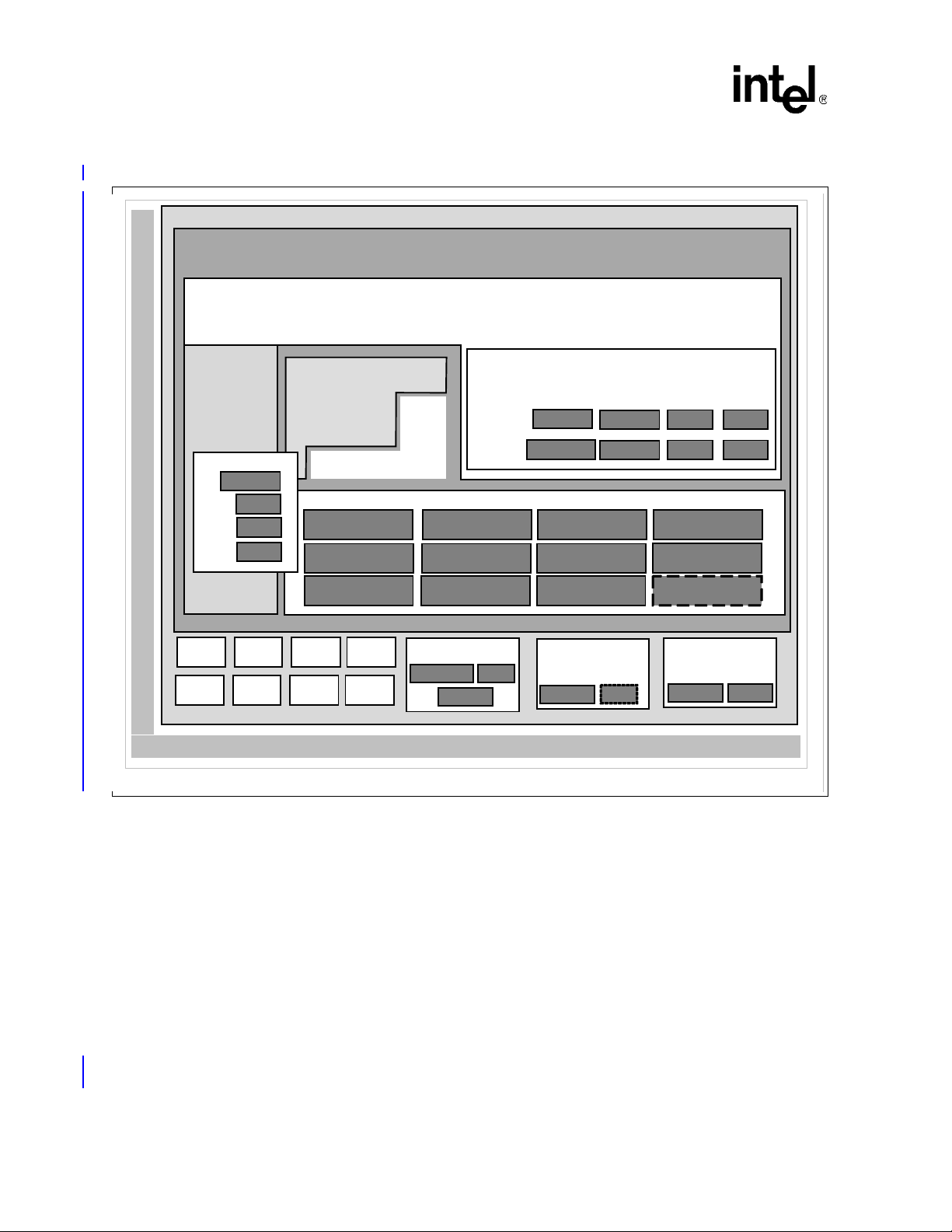
Intel® IXP400 Software
Software Architecture Over view
Figure 1. Intel
Intel® IX P4 X X N etwor k P ro cesso r
Intel XScale® Core
®
IXP400 Software v2.0 Architecture Block Diagram
Board
Support
Package
Drivers
Ethernet
ADSL
I2C
USB
Custom er Applicat ion
Operating System
Parity
OSAL
OSSL
IxAtmdAcc Ix C ryptoAcc
IxHssAcc
IxTimeSyncAcc IxNpeMhIxSspAcc ix...Acc
IxQmgr
TimeSync
Ethernet
IxDmaAcc
IxNpeDl
Codelets
ATM
HSSPerf Prof Crypto
Access Layer
IxEthAcc
IxParityENAcc
DMA
GPIO PCI UART
IEEE
1588
SSP I2C MCU
USB
2.2 Deliverable Model
Intel® IXP400 Software v2.0 consists of these elements:
®
• Intel
• Complete documentation and source code for IXP400 software com ponents
• NPE microcode images
• Example codelets
Note: The software releases do not include tools to develop NPE software. The supplied NPE
functionality is accessible through the access-layer APIs provided by the software release 2.0
library. The NPE microcode is provided as a .c file that must be compiled with the access-layer
library. NPE microcode is compatible only with the specific access-layer it is provided with.
IXP400 Software v2.0 access-layer components and OSAL layer
NPE - A
UTOPIA II
Ethernet
Board Har dwar e
HSS
NPE -B
Ethernet
DMA
NPE -C
Ethernet Crypto
B2909-05
April 2005 IXP400 Software Version 2.0 Programmer’s Guide
28 Document Number: 252539, Revision: 007
Page 29

2.3 Operating System Support
The Intel XScale microarchitecture offers a broad range of tools together with support for two
widely adopted operating systems. The software release 2.0 supports VxWorks* and the standard
Linux* 2.4 kernel. MontaVista* software will provide the support for Linux. Support for other
operating systems may be available. For further information, visit the following Internet site:
http://developer.intel.com/design/network/products/npfamily/ixp425.htm
The software release 2.0’s software library is OS-i ndependent in tha t all components are written in
ANSI-C with no direct calls to any OS library function that is not covered by ANSI-C. A thin
abstraction layer is provided for some operating services (timers, mutexs, semiphores, and thread
management), which can be readily modified to support additional operating systems. This enables
the devices to be compatible with multiple operating systems and allows customers the flexibility
to port the IXP4XX product line and IXC1100 control plane processors to their OS of choice.
2.4 Development Tools
The Intel XScale microarchitecture offers a broad range of tools together with support for two
widely adopted operating systems. Developers have a wide choice of third-party tools including
compilers, linkers, debuggers and board-support packages (BSPs). Tools include Wind River*
Tornado* 2.2.1 for the VxWorks 5.5.1 real-time operating system, Wind River’s PLATFORM for
Network Equipment* and the complete GNU* Linux* development suite.
Intel® IXP400 Software
Software Architecture Over view
Refer to the release notes accompanying the software for information on specific OS support.
2.5 Access Library Source Code Documentation
The access library source code uses a commenting style that supports the Doxygen* tool for use in
creating source code documentation. Doxygen is an open-source tool, that reads appropriately
commented source code and produces hyper-linked documentation of the APIs suitable for on-line
browsing (HTML).
The documentation output is typically multiple HTML files, but Doxygen can be configured to
produce LaTeX*, RTF (Rich Text Format*), PostScript, hyper-linked PDF, compressed HTML,
and Unix* man pages. Doxygen is available for Linux, Windows* and other operating systems.
For more information, use the following Web URL:
http://www.doxygen.org.
The IXP400 software compressed file contains the HTML source code documentation at
ixp400_xscale_sw\doc\index.html. This output is suitable for online browsing. For a
printable reference, see the Adobe* Portable Document Format (PDF) file, contained in the
compressed software-download file.
Programmer’s Guide IXP400 Software Version 2.0 April 2005
Document Number: 252539, Revision: 007 29
Page 30

Intel® IXP400 Software
Software Architecture Over view
2.6 Release Directory Structure
The software release 2.0 includes the following directory structure:
\---ixp_osal
+---doc
+---include
+---os
+---src
\---ixp400_xscale_sw
+---buildUtils
+---doc (API Reference in HTML and PDF format)
\---src (contains access-layer and codelet source code)
+---adsl (separate package)
+---atmdAcc
+---atmm
+---atmsch
+---codelets
| +---atm
(API References in HTML and PDF format)
(setting environment vars. in VxWorks and Linux)
(sub-directory for codelet source)
| +---cryptoAcc
| +---dmaAcc
| +---ethAal5App
| +---ethAcc
| +---hssAcc
| +---parityENAcc
| +---perfProfAcc
| +---timeSyncAcc
| \---usb
| +---drivers
| \---include
April 2005 IXP400 Software Version 2.0 Programmer’s Guide
30 Document Number: 252539, Revision: 007
(separate package)
(for crypto version only)
Page 31

Intel® IXP400 Software
Software Architecture Over view
+---cryptoAcc
+---dmaAcc
+---ethAcc
| \---include
+---ethDB
| \---include
+---ethMii
+---featureCtrl
+---hssAcc
| \---include
+---i2c
+---include
(header location for top-level public modules)
+---npeDl
| \---include
(for crypto version only)
+---npeMh
| \---include
+---osLinux
(Linux specific operations for loading NPE microcode)
+---osServices (v1.4 backwards compatibility)
+---ossl (v1.4 backwards compatibility)
+---parityENAcc
+---perfProfAcc
+---qmgr
+---sspAcc
+---timeSyncAcc
+---uartAcc
| \---include
\---usb
\---include
Programmer’s Guide IXP400 Software Version 2.0 April 2005
Document Number: 252539, Revision: 007 31
Page 32

Intel® IXP400 Software
Software Architecture Over view
2.7 Threading and Locking Policy
The software release 2.0 access-layer does not implement processes or threads. The architecture
assumes execution within a preemptive multi-tasking environment with the existence of multipleclient threads and uses common, real-time OS functions — such as semaphores, task locking, and
interrupt control — to protect critical data and procedure sequencing. These functions are not
provided directly by the OS, but by the OS abstraction components.
2.8 Polled and Interrupt Operation
It is possible to use access-layer components by running the Queue Manager in a polled mode or in
an interrupt driven mode of operation. A customers application code may be invoked by registering
with the callback mechanisms provided in the access-layer components. Access-layer components
do not autonomously bind themselves to interrupts but generally may be dispatched by an interrupt
service routine that is bound to the Queue Manager interrupts. Or, a timer-based task may
periodically check the queue manager status and dispatch the access-layer components that are
registered to specific queues. Refer to Chapter 18 for additional information.
All data path interfaces are executable in the context of both IRQ and FIQ interrupts, though not all
operating systems may take advantage of FIQ interrupts in their default configuration.
2.9 Statistics and MIBs
The software release 2.0 access-layer components only maintain statistics that access-layer clients
cannot collect of their own accord. The access-layer components do not provide management
interfaces (MIBs). Access-layer clients can use the statistics provided to implement their own
MIBs.
April 2005 IXP400 Software Version 2.0 Programmer’s Guide
32 Document Number: 252539, Revision: 007
Page 33

2.10 Global Dependency Chart
Figure 2 shows the interdependencies for the major APIs discussed in this document.
Figure 2. Global Dependencies
Intel® IXP400 Software
Software Architecture Over view
EthAcc
EthDB EthMii
I2CDrv
HssAcc
NpeDl NpeMh
DmaAcc
FeatureCtrl
Adsl
Usb
IxOSAL
CryptoAcc
PerfProfAcc
QMgr
Atmm
AtmdAcc
AtmSch
SspAcc
TimeSyncAcc
ParityENAcc
UartAcc
B2922-03
Programmer’s Guide IXP400 Software Version 2.0 April 2005
Document Number: 252539, Revision: 007 33
Page 34

Intel® IXP400 Software
This page is intentionally left blank.
April 2005 IXP400 Software Version 2.0 Programmer’s Guide
34 Document Number: 252539, Revision: 007
Page 35

Intel® IXP400 Software
Buffer Management 3
This chapter describes the data buffer system used in Intel® IXP400 Software v2.0, and includes
definitions of the IXP400 software internal memory buffers, cache management strategies, and
other related information.
3.1 What’s New
There are no changes or enhancements to this component in software release 2.0.
3.2 Overview
Buffer management is the general principle of how and where network data buffers are allocated
and freed in the entire system. Network data buffers, whose formats are known to all involved
components, need to flow between access-layer components.
As shown in Figure 3, the IXP400 software access-layer follows a simple buffer-management
principle: All buffers used between access-layer component and clients above the access-layer
component must be allocated and freed by the clients, that is, in this case, the operating system
driver. The client passes a buf fer to an access-layer component for various purposes (generally, Tx
and Rx), and the access-layer component returns the buffer to the client when the requested job is
completed. The access-layer component’s Operating System Abstraction Layer module provides
the mapping of the OS buffer header fields to the IXP buffer format. Clients can also implement
their own utilities to convert their buffers to the IXP_BUF format and vice-versa. Depending upon
the service requested, the NPE modifies the IXP_BUF’s shared structure and hands the buf fer back
to the access-layer component. The Figure 3 shows diff erent stages where the different fields in the
IXP_BUF buffer gets updated at transmit and receive time.
Programmer’s Guide IXP400 Software Version 2.0 April 2005
Document Number: 252539, Revision: 007 35
Page 36

Intel® IXP400 Software
Buffer Management
Figure 3. Intel
ix_ctrl: Pool management
®
IXP400 Software Buffer Flow
OS NPE
OS buffer
Receive
Driver
Transmit
OS buffer
fields gets updated
Access-layer Components
Allocate
IXP_BUF
buffer
Translation
OSBUF<->IXP_BUF
Free IXP_BUF
buffer
IX_MBUF: OS specific
structure gets updated
AQM
RxFree Q
Rx Q
Tx Q
TxDone Q
ix_ne: shared structure gets
updated
Update
IXP_BUF
:ixp_ne
structure
Update
IXP_BUF
:ixp_ne
structure
B-3824
The access-layer component may call a client-registered callback function to return the buffer, or
may put the buffer back on a free queue for the client to poll. The access-layer components utilize
similar buffer management techniques when communicating with the NPEs.
The network data buffers and their formats (as well as management of the buffers), must be
‘familiar’ to all components so that the buffers can efficiently flow in the system. The IXP400
software uses two internal buffer formats for all network data:
• IXP_BUF
• raw buffer
These two formats are compatible with the IXP400 software’s access-layer components and NPEs.
IXP_BUF
The IXP_BUF is the Intel
components. As shown in Figure 4, the Operating System Abstraction Layer of Intel
Software v2.0 provides the users with macros to read and write the IX_OSAL_MBUF fields of the
IXP_BUF buffer. The Intel
macros provided with the API to access the IX_OSAL_MBUF fields.
®
IXP400 Software defined buffer format used by the access-layer
®
IXP400 Software v2.0 users are expected to use the IX_MBUF_xxx
®
IXP400
April 2005 IXP400 Software Version 2.0 Programmer’s Guide
36 Document Number: 252539, Revision: 007
Page 37

Figure 4. IXP_BUF User Interface
Intel® IXP400 Software
Buffer Management
Users
IXP_BUF macros
IX_OSAL_MBUF fields
IXP_BUF structure
B-3825
The usual fields to be updated between the user and the IXP_MBUF fields depends on the accesslayer component, but most of the Intel
®
IXP400 Software API requires the use of following fields:
— IX_DATA
— IX_MLEN
— IX_PKTLEN
— IX_NEXT_BUFFER_IN_PKT_PTR (in case of chained buffers)
Raw Buffers
Raw buffer format is simply a contiguous section of memory represented in one of two ways. One
way to pass raw buffers between two access-layer components is through an agreement to
circularly access the same piece of raw buffer . One access-layer component circularly writes to the
buffer while the other access-layer component circularly reads from the buffer. The buffer length
and alignment are parts of the agreement. At run-time, another communication channel is needed
to synchronize the read pointer and write pointers between the two components.
The other way to pass raw buffers between two components is through passing a pointer to the
buffer between the components. If all buffers are the same size and that size is fixed, the length can
be made known during configuration. Otherwise, another communication channel in run-time is
needed to tell the length of the buffer. The raw buffer component is typically used for circuitswitched network data (that is, TDM-based). The access-layer component IxHssAcc channelized
service uses raw buffers. Refer to Section 13.7.2 for additional information on raw buffers.
Note: Intel
®
IXP400 Software provides OSAL macros, which can be used to allocate memory for raw
buffers as a substitute to allocating IXP_BUF from the pool.
Programmer’s Guide IXP400 Software Version 2.0 April 2005
Document Number: 252539, Revision: 007 37
Page 38

Intel® IXP400 Software
Buffer Management
3.3 IXP_BUF Structure
As shown in Figure 5, IXP_BUF is comprised of the following three main structures, and each
structure is comprised of eight entries four bytes long.
1. The first structure consists of an eight word fields some of which are between the OS driver /
API users and the access-layer components.
2. The second structure consists of internal fields used by the pool manager, which is provided by
the OSAL component.
3. The third structure is the NPE Shared structure that is composed of common header fields and
NPE service specific fields. Depending upon the access-component usage, some of the service
specific fields such as VLAN tags may be available for the user through use of macros.
Figure 5. IXP_BUF Structure
Structure 1
IX_MBUF: OS Dependent Buffer format
ix_ctrl: Pool Management Fields
Structure 2
ix_ne: NPE Shared structure
Structure 3
IXP_BUF structure
3.3.1 IXP_BUF Structure and Macros
Users are expected to use the following IXP_BUF macros provided to access IXP_BUF subfields.
The Figure 6 shows macros defined by the OSAL layer component to be used to access the
IXP_BUF fields.
B-3826
April 2005 IXP400 Software Version 2.0 Programmer’s Guide
38 Document Number: 252539, Revision: 007
Page 39

Figure 6. OSAL IXP_BUF structure and macros
Intel® IXP400 Software
Buffer Management
OSAL macros for IXP400 IXP_BUFIXP_BUF fields
Cache Line
Cache Line
Cache Line
ix_next
ix_nextPacket
ix_data
ix_len
ix_type ix_flags ix_reserved
ix_rsvd
ix_PktLen
ix_priv
Reserved
Reserved
ix_signature
ix_allocated_len
ix_allocated_data
ix_pool
ix_chain
ix_osbuf_ptr
Reserved (Shared with NPE)
Reserved (Shared with NPE)
Reserved (Shared with NPE)
Reserved (Shared with NPE)
Reserved (Shared with NPE)
Reserved (Shared with NPE)
Reserved (Shared with NPE)
Reserved (Shared with NPE)
IX_OSAL_MBUF_NEXT_BUFFER_IN_PKT_PTR
IX_OSAL_MBUF_NEXT_PKT_IN_CHAIN_PTR
IX_OSAL_MBUF_MDATA
IX_OSAL_MBUF_MLEN
IX_OSAL_MBUF_MTYPE/MFLAGS
IX_OSAL_MBUF_PKT_LEN
IX_OSAL_MBUF_PRIV
IX_OSAL_MBUF_SIGNATURE
IX_OSAL_MBUF_ALLOCATED_MBUF_LEN
IX_OSAL_MBUF_ALLOCATED_MBUF_DATA
IX_OSAL_MBUF_NET_POOL
IX_OSAL_MBUF_OSBUF_PTR
User visible
Shared with NPE
IXP400 SW v1.4
v1.5 Pool management
OS dependent fields, not m od ified by access-layer comp one nt
OS dependent fields, may be modified by access-layer componentUser visible
Reserved for NPE-Service specific usage
Fields used by Intel IXP400 version 1.4
Used by Intel IXP400 SW v1.5 for pool mana gem e nt / Reser ve d
B-3827
Depending upon the usage model, different software components use the structures to update the
internal fields of the IXP_BUF structure. Figure 7 shows a typical interface for the API users or
operating system drivers to the IXP_BUF fields. Depending upon the access-layer components in
use the API user may or may not use the service-specific macros to read the NPE-shared structure
of the IXP_BUF fields. Reading of the MAC address or a VLAN tag for a quick classification is an
example of NPE-shared structure use.
Programmer’s Guide IXP400 Software Version 2.0 April 2005
Document Number: 252539, Revision: 007 39
Page 40

Intel® IXP400 Software
Buffer Management
Figure 7. API User Interface to IXP_BUF
IXP_BUF
API USER
IX_OSAL_MBUF_XXX
macros (data, length …)
API User
(e.g. driver)
IX_ETHACC_NE_XXX
service-specific macros
(e.g. flags)
The Figure 8 shows a typical interface between the Intel
components and the IXP_BUF fields. The access-layer components adapt to the endianness as
defined by the Intel XScale core. The access-layer components can perform reads and write to the
IX_MBUF fields as well as the NPE-shared structure. The service-specific fields to be updated in
the NPE-shared structure may vary depending upon access-component needs.
Figure 8. Access-Layer Component Interface to IXP_BUF
IX_MBUF
Data, len …
same fields across all APIs)
Reserved for pool
management and extra fields
ix_ne: NPE shared structure
(service specific)
B-3828
®
IXP400 Software access-layer
IXP_BUF
ACCESS-LAYER components
Access-layer components
IX_OSAL_MBUF_XXX
macros
IX_Component_NE_XXX
service-specific macros
same fields across all APIs)
management and extra fields
ix_ne: NPE Shared structure
IX_MBUF
Data, len …
Reserved for pool
(service specific)
B-3829
April 2005 IXP400 Software Version 2.0 Programmer’s Guide
40 Document Number: 252539, Revision: 007
Page 41

Figure 9 below shows the interface between the OSAL pool management module and the pool
management fields used for pool maintenance. The pool management field also stores the
os_buf_ptr field, which is used by the access-layer to retrieve the original pointer to the OS buffer
and is set at the time of pool allocation.
Figure 9. Pool Management Fields
Intel® IXP400 Software
Buffer Management
IXP_BUF
IX_OSAL_MBUF_POOL
Pool manager
field macros and field
names
IX_MBUF: OS-Dependent Buffer Format
As shown in Figure 10, the IX_MBUF information follows a format originally defined in Berkeley
Software Distribution (BSD) TCP/IP code distribution to preserve the backward compatibility with
previous Intel
®
IXP400 Software releases. The OSAL layer provides translation functions to map
the OS-dependent buffer format to the IX_MBUF format for Linux* and VxWorks* operating
systems. This simplifies the buffer management without sacrificing functionality and flexibility.
Figure 10. IXP_BUF: IX_MBUF Structure
IX_MBUF
Data, len …
(standard along CSR APIs)
Reserved for pool
management and extra fields
ix_ne: NPE Shared structure
(service specific)
ix_next
ix_nextpacket
ix_data
ix_len
ix_t ype ix_flags
ix_rsvd
ix_Pk tL en
Reserved
ix_reserved
IX_MBUF: 1st Structure of IXP_BUF
(IX_MBUF fie ld s )
Programmer’s Guide IXP400 Software Version 2.0 April 2005
Document Number: 252539, Revision: 007 41
Page 42

Intel® IXP400 Software
Buffer Management
Linux utilizes memory structures called skbuffs. The user allocates IXP_BUF and sets the data
payload pointer to the skbuff payload pointer. An os_buf_ptr field inside the ixp_ctrl structure
(defined below) of the IXP_BUF is used to save the actual skbuff pointer. In this manner, the OS
buffers are not freed directly by the IXP400 software.
The IXP400 software IXP_BUF to skbuff mapping is a ‘zero-copy’ implementation. There is no
copy/performance penalty in using Linux skbuffs. Other proprietary buffer schemes could also be
implemented with the IXP400 software using the mbuf-to-skbuff implementation as an example.
ix_ctrl: Intel
®
IXP400 Software Internal Pool Management Fields
As shown in Figure 11, the ix_ctrl fields are set and used by the IXP_BUF pool manager provided
by the OSAL component. Some of the fields can be used for specific purposes for different
operating systems For example, signature verification fields is used in Linux when NDEBUG is
enabled. The reserved field may be used in VxWorks to support IPv6 format.
Figure 11. IXP_BUF: ix_ctrl Structure
Reserved
Reserved
ix_signa ture
ix_allocated_len
ix_allocated_data
ix_pool
ix_chain
ix_osbuf_ptr
ix_ctrl: 2nd Structure of IX _B U F
(Internal fie ld s )
ix_ne: IXP400 NPE Shared Structure
As shown in Figure 12, this structure is provided by the Intel XScale core to the NPE. Depending
upon the access-layer component usage, some of these fields may be visible to the user through use
of macros and also may be altered by the NPE. The lower five words of this structure are defined
according to the needs of NPE microcode; therefore, different NPE images may have different
structure for this part. The upper three words follows the same structure across all the NPE images.
Note: Users should not make any assumptions to usage of the service-specific fields in this NPE-shared
structure. The fields are for internal NPE usage only.
April 2005 IXP400 Software Version 2.0 Programmer’s Guide
42 Document Number: 252539, Revision: 007
Page 43

Intel® IXP400 Software
Buffer Management
Figure 12. IXP_BUF: NPE Shared Structure
ixp_next
ixp_len ixp_pkt_len
ixp_data
NPE Service Specific Field
NPE Service Specific Field
NPE Service Specific Field
NPE Service Specific Field
NPE Service Specific Field
ix_ne: 3rd Structure of IX_B UF
(NPE S hared structure)
3.4 Mapping of IX_MBUF to Shared Structure
The Figure 13 below shows an example case on how the IX_MBUF headers are int ernal ly mapp ed
to the NPE shared structure as in the case of the Ethernet and Crypto access-layer components only.
The IX_MBUF standard buffer format is used throughout the access-layer code. In order to
minimize overhead in reading the whole buffer control structure from the memory to the NPE
while performing NPE-specific services, the pointer to the NPE shared structure is passed to the
NPE for processing the data instead of the buffer descriptor pointer itself. Therefore, for the accesslayer components, only the required information (such as next buffer pointer, buffer data pointer,
buffer length and packet length) from the buffer control structure is copied into NPE shared
structure. Depending upon the endianness, the IXP400 software internally swaps the buffers of
packetised data and the headers between the upper software layers and the NPEs for the Ethernet
and the Crypto access-layer components. It is important to note that NPE shared buffer format used
by the IXP400 software is hard-coded in the NPE microcode. It is not possible to change this
shared buffer format.
Programmer’s Guide IXP400 Software Version 2.0 April 2005
Document Number: 252539, Revision: 007 43
Page 44
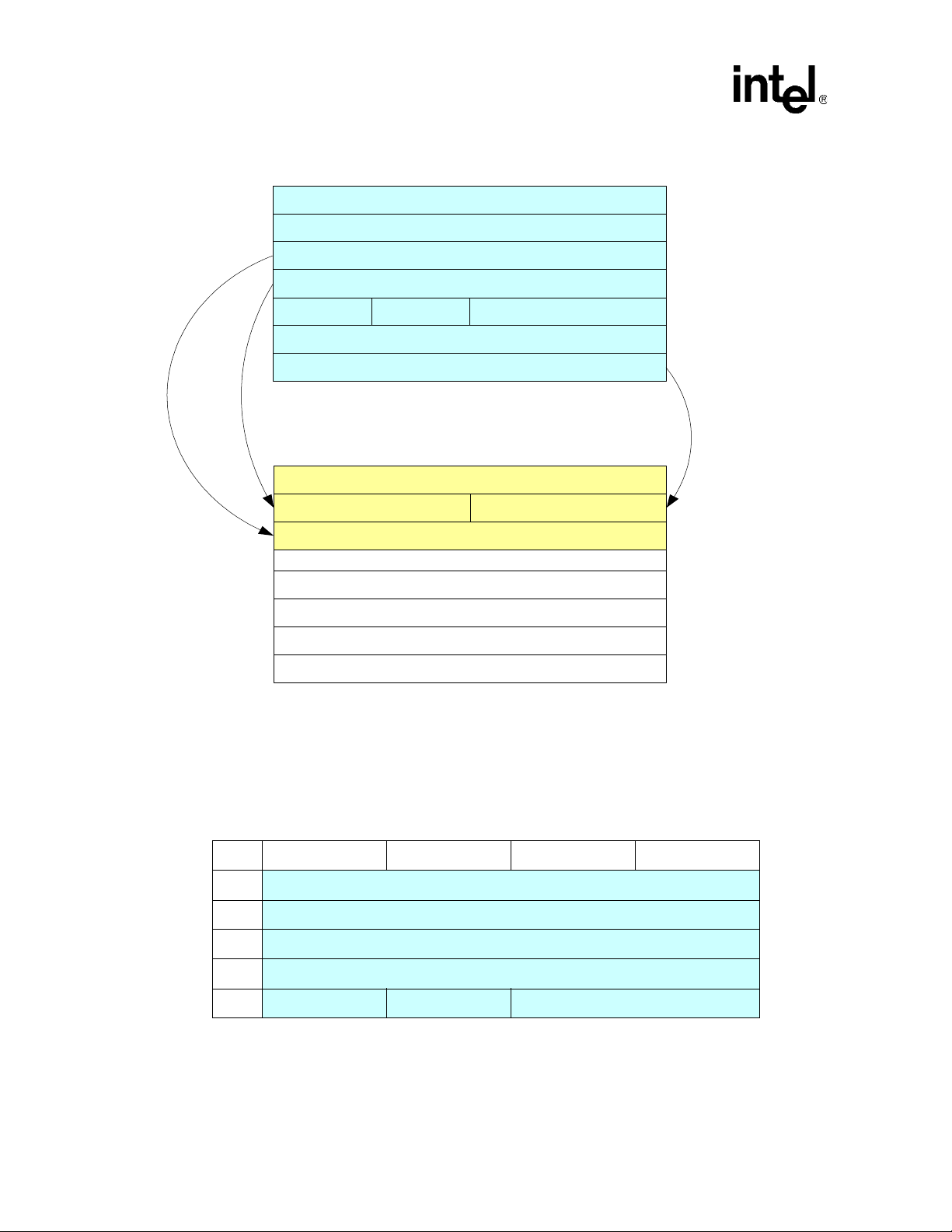
Intel® IXP400 Software
Buffer Management
Figure 13. Internal Mapping of IX_MBUF to the Shared NPE Structure
ix_next
ix_nextpkt
ix_data
ix_ le n
ix_ ty p e ix_flags
ix_rs vd
ix_len
Mapping from IX_MBUF to NPE Shared
Structure
ixp_next
ixp_len ixp_pkt_len
ixp_data
NPE S ervice Specific Field
NPE S ervice Specific Field
ix_reserved
1st Cache
lin e o f
IXP_BUF
2nd Cach e
lin e o f
IXP_BUF
NPE S ervice Specific Field
NPE S ervice Specific Field
NPE S ervice Specific Field
3.5 IX_MBUF Structure
Table 1 and Table 2 present IX_MBUF structure format and details.
Table 1. Internal IX_MBUF Field Format (Sheet 1 of 2)
0123
0
4
8
12
16
ix_next (IX_OSAL_MBUF_NEXT_BUFFER_IN_PKT_PTR)
ix_nextPacket (IX_OSAL_MBUF_NEXT_PKT_IN_CHAIN_PTR)
ix_data (IX_OSAL_MBUF_MDATA)
ix_len (IX_OSAL_MBUF_MLEN)
ix_type ix_flags ix_reserved
April 2005 IXP400 Software Version 2.0 Programmer’s Guide
44 Document Number: 252539, Revision: 007
Page 45

Table 1. Internal IX_MBUF Field Format (Sheet 2 of 2)
0123
20 ix_rsvd
Intel® IXP400 Software
Buffer Management
24
28
ix_pktlen
ix_priv(Reserved)
A set of macros are provided for the IXP400 software to access each of the fields in the buffer
structure. Each macro takes a single parameter – a pointer to the buffer itself. Each macro returns
the value stored in the field. More detail on the field, their usage, and the macros are detailed in the
table below.
Note: The data pointer IX_OSAL_MBUF_MDATA could be aligned on a 16 bit boundary to help align
an IP header on a 32 bit boundary.
Table 2. IX_MBUF Field Details (Sheet 1 of 2)
Field / MACRO Purpose Used by Access-Layer?
IX_OSAL_MBUF_NEXT_BUFFER_IN_PK
T_PTR
Parameter type: IX_MBUF *
Return type: IX_MBUF *
Description: Returns a 32-bit pointer to the
next buffer in the packet
IX_OSAL_MBUF_NEXT_PKT_IN_CHAIN_
PTR
Parameter type: IX_MBUF *
Return type: IX_MBUF *
Description: Returns a 32-bit pointer to the
first buffer in the next packet in the packet
chain
IX_OSAL_MBUF_MDATA
Parameter type: IX_MBUF *
Return type: char *
Description: Returns a pointer to the first
byte of the buffer data
IX_OSAL_MBUF_MLEN
Parameter type: IX_MBUF *
Return type: int
Description: Returns the number of octets of
valid data in the data section of the buffer
IX_OSAL_MBUF_TYPE
Parameter type: IX_MBUF *
Return type: unsigned char
Description: Returns the type field of the
buffer
32-bit pointer to the next buffer in a
chain (linked list) of buffers. NULL
entry marks end of chain.
32-bit pointer to the next packet in a
chain (linked list) of packets. NULL
entry marks end of chain. Each
packet in the chain may consist of a
chain of buffers.
32-bit pointer to the data section of a
buffer. The data section typically
contains the payload of a network
buffer.
Lengths (octets) of valid data in the
data section of the buffer.
Buffer type Yes, by some components.
Yes, where buffer chaining is
supported.
No. Packet chaining is not supported
by IXP400 Software.
Yes. But does not get modified by the
access-layer
Yes.
Programmer’s Guide IXP400 Software Version 2.0 April 2005
Document Number: 252539, Revision: 007 45
Page 46

Intel® IXP400 Software
Buffer Management
Table 2. IX_MBUF Field Details (Sheet 2 of 2)
Field / MACRO Purpose Used by Access-Layer?
IX_OSAL_MBUF_FLAGS
Parameter type: IX_MBUF *
Return type: unsigned char
Description: Returns the flags field of the
buffer
Reserved
IX_OSAL_MBUF_NET_POOL
Parameter type: IX_MBUF *
Return type: unsigned int
Description: Returns a 32-bit pointer to the
parent pool of the buffer
IX_OSAL_MBUF_PKT_LEN
Parameter type: IX_MBUF *
Return type: unsigned int
Description: Returns the length of the packet
(typically stored in the first buffer of the
packet only)
Reserved Used by VxWorks* No.
Buffer flags. Yes, by some components.
Reserved field, used to preserve 32bit word alignment.
32-bit pointer to the parent pool of
the buffer
Total length (octets) of the data
sections of all buffers in a chain of
buffers (packet). Typically set only in
the first buffer in the chain (packet).
No.
Yes, by some components.
Yes, where buffer chaining is
supported.
3.6 Mapping to OS Native Buffer Types
OSAL provides buffer-translation macros for users to translate OS-specific buffer formats to
OSAL IXP buffer format and vice versa. The mapping of OS buffer fields to the IXP400 software
buffer format is usually done in the OS specific driver component. However, for ease of users the
OSAL component provides generic macros for VxW orks, and Linux operating system that does the
translation. Depending upon the build, the OSAL component will translate the macros to its OSspecific implementation. The general syntax for using these macros is as follows:
• IX_OSAL_CONVERT_OSBUF_TO_IXPBUF(osBufPtr,ixpBufPtr)
• IX_OSAL_CONVERT_IXPBUF_TO_OS_BUF(ixpBufPtr,osBufPtr)
These macros are intended to replace Linux skbuf and VxWorks mbuf conversions. Users can also
define their own conversion utilities in their package to translate their buffers to IXP buffers
(IX_OSAL_MBUF).
3.6.1 VxWorks* M_BLK Buffer
The first structure IX_MBUF of the IXP_BUF buffer format is compatible with VxWorks M_BLK
structure. It is also intended to provide a backward compatibility to previous Intel
Software release. For this reason, when compiled for VxWorks, the IX_MBUF buffer format is
compatible directly as an M_BLK buffer . The Intel
fields defined by the M_BLK buf fer. The macros listed in Table 3 are used by the IXP400 software
to access the correct fields within the M_BLK structure.
®
IXP400 Software does not make use of all the
®
IXP400
The M_BLK structure is defined in the global VxWorks header file “netBufLib.h”.
April 2005 IXP400 Software Version 2.0 Programmer’s Guide
46 Document Number: 252539, Revision: 007
Page 47

Intel® IXP400 Software
Buffer Management
Note that the M_BLK structure contains many fields that are not used by the IXP400 software.
These fields are simply ignored and are not modified by the IXP400 software.
M_BLK buffers support two levels of buffer chaining:
• buffer chaining — Each buffer can be chained together to form a packet. This is achieved
using the IX_MBUF_NEXT_BUFFER_IN_PKT_PTR equivalent field in the M_BLK. This
is supported and required by the IXP400 software.
• packet chaining — Each packet can consist of a chain of one or more buffers. Packets can also
be chained together (to form a chain of chains). This is not used by the IXP400 software. The
IX_MBUF_NEXT_PKT_IN_CHAIN_PTR equivalent field of the M_BLK buffer structure is
used for this purpose. Most IXP400 software components will ignore this field.
Note: The VxWorks netMbuf pool library functions will not be supported to allocate and free the
IXP_BUF buffers.
Table 3 shows the field mapping between the IX_MBUF and the M_BLK buffer structures through
OSAL macros.
Table 3. IX_MBUF to M_BLK Mapping
IX_MBUF M_BLK
IX_OSAL_MBUF_NEXT_BUFFER_IN_PKT_PTR mBlkHdr.mNext
IX_OSAL_MBUF_NEXT_PKT_IN_CHAIN_PTR mBlkHdr.mNextPkt
IX_OSAL_MBUF_MDATA mBlkHdr.mData
IX_OSAL_MBUF_MLEN mBlkHdr.mLen
IX_OSAL_MBUF_TYPE mBlkHdr.mType
IX_OSAL_MBUF_FLAGS mBlkHdr.mFlags
IX_OSAL_reserved mBlkHdr.reserved
IX_OSAL_MBUF_NET_POOL mBlkPktHdr.rcvif
IX_OSAL_MBUF_PKT_LEN mBlkPktHdr.len
priv pClBlk
3.6.2 Linux* skbuff Buffer
The buffer format native to the Linux OS is the “skbuff” buffer structure, which is significantly
different from the IX_MBUF buffer format used by the IXP400 software.
The Linux skbuf structure is attached to the os_buf_ptr field during transmit or receive and is
detached during TxDone. The user must allocate an IXP_BUF header, make a call to a translational
function and pass the IXP_BUF buffer to the IXP400 software release. The translation functions
enter all the required fields from the OS buffers to respective fields in the first structure, that is, the
IX_MBUF structure within the IXP_BUF structure. The translation of fields from the IX_MBUF
structure into the NPE shared structure is accomplished by the OSAL component on Transmit and
Receive Replenish. On TxDone the user may recycle the IXP_BUF back to the IXP_BUF_POOL
or to an internal data structure.
The OSAL layer provides buffer translation macros for users to translate OS-specific buffer
formats to IXP_BUF buffer format and vice versa.
Programmer’s Guide IXP400 Software Version 2.0 April 2005
Document Number: 252539, Revision: 007 47
Page 48

Intel® IXP400 Software
Buffer Management
It works on the following principles:
• Each IXP_BUF is mapped to an skbuff (1:1 mapping)
• The os_buf_ptr field of the ix_ctrl structure is used to store a pointer to the corresponding
skbuff.
• The ix_data pointer field of the IX_MBUF structure within the IXP_BUF structure will be set
to point to the data field of the corresponding skbuff through use of the
IX_OSAL_MBUF_MDATA macro.
• The ix_len and ix_pkt_len fields of the IX_MBUF structure within the IXP_BUF structure
will be set to the length of the skbuff data section (the len field in the skbuff structure) through
use of the IX_OSAL_MBUF_PKT_LEN and IX_OSAL_MBUF_MLEN macros.
The prototype for this function is shown in Table 4.
Table 4. Buffer Translation Functions
• IX_OSAL_CONVERT_OSBUF_TO_IXPBUF(osBufPtr,ixpBufPtr)
The following fields of IX_MBUF within the IXP_BUF structure
will get updated:
— ix_len
— ix_pktlen
— ix_data
— ix_ctrl.os_buf_ptr
• IX_OSAL_CONVERT_IXPBUF_TO_OS_BUF(ixpBufPtr)
The following fields will get updated in the skbuffer
— (skb)osBufPtr = ix_ctrl.os_buf_ptr
— skb->data = IX_OSAL_MBUF_MDATA(ixMbufPtr)
— skb->len = IX_OSAL_MBUF_MLEN(ixMbufPtr)
— skb->len = IX_OSAL_MBUF_PKT_LEN(ixMbufPtr)
The suggested usage model of this function is:
• Allocate a pool of IXP_BUF buffer headers. Do not allocate data sections for these buffers.
• When passing a buffer from higher-level software (for example, OS network stack) to the
IXP400 software, attach the skbuff to an IXP_BUF using the translation function.
• When receiving an IXP_BUF passed from the IXP400 software to higher-level software, use
the translation function to retrieve a pointer to the skbuff that was attached to the IXP_BUF,
and use that skbuff with the OS network stack to process the data.
The Intel
the IXP400 software distribution in form of a patch, contain s an example of this suggest ed usage
model.
®
IXP400 Software Linux Ethernet Device driver (“ixp425_eth.c”), which is included in
April 2005 IXP400 Software Version 2.0 Programmer’s Guide
48 Document Number: 252539, Revision: 007
Page 49

3.7 Caching Strategy
The general caching strategy in the IXP400 software architecture is that the software (include Intel
XScale core-based code and NPE microcode) only concerns itself with the parts of a buffer which
it modifies. For all other parts of the buffer, the user (higher-level software) is entirely responsible.
IXP_BUF buffers typically contain a header section and a data section. The header section contains
fields that can be used and modified by the IXP400 software and the NPEs. Examples of such
fields are:
• pointer to the data section of the IXP_BUF
• length of the data section of the mbuf
• pointer to the next mbuf in a chain of mbufs
• buffer type field
• buffer flags field
As a general rule, IXP400 software concerns itself only with IXP_BUF headers, and assumes that
the user (that is, higher-level software) will handle the data section of buffer.
The use of cached memory for IXP_BUF buffer is strongly encouraged, as it will result in a
performance gain as the buffer data is accessed many times up through the higher layers of the
operating system’s network stack. However, use of cached memory has some implications that
need to be considered when used for buffers passed through the IXP400 software Access-Layer.
Intel® IXP400 Software
Buffer Management
The code that executes on Intel XScale core accesses the buffer memory via the cache in the Intel
XScale core MMU. However, the NPEs bypass the cache and access this external SDRAM
memory directly. This has different implications for buffers transmitted from Intel XScale core to
NPE (Tx path), and for buffers received from NPE to Intel XScale core (Rx path).
3.7.1 Tx Path
If a buffer in cached memory has been altered by Intel XScale core code, the change will exist in
the cached copy of the IXP_BUF , but may not be written to memory yet. In order to ensure tha t the
memory is up-to-date, the portion of cache containing the altered data must be flushed.
The cache flushing strategy uses the following general guidelines:
• The “user” is responsible for flushing the data section of the IXP_BUF. Only those portions of
the data section which have been altered by the Intel XScale core code need to be flushed. This
must be done before submitting an IXP_BUF to the IXP400 software for transmission via the
component APIs (for example, ixEthAccPortTxFrameSubmit().
• The IXP400 software is responsible for writing and flushing the ix_ne shared section of the
buffer header. This must be done before submitting an IXP_BUF to the NPE. Communication
to the NPEs is generally performed by access-layer components by sending IXP_BUF headers
through the IxQMgr queues.
Since flushing portions of the cache is an expensive operation in terms of CPU cycles, it is not
advisable to simply flush both the header and data sections of each IXP_BUF. To minimize the
performance impact of cache-flushing, the IXP400 software only flushes that which it modifies
(the IXP_BUF header) and leaves the flushing of the data section as the responsibility of the user.
The user can minimize the performance impact by flushing only what it needs to.
Programmer’s Guide IXP400 Software Version 2.0 April 2005
Document Number: 252539, Revision: 007 49
Page 50

Intel® IXP400 Software
Buffer Management
Tx Cache Flushing Example
In the case of an Ethernet bridging system, only the user can determine that it is not necessary to
flush any part of the packet payload. In a routing environment, the stack can determine that only
the beginning of the mbuf may need to be flushed (for example, if the TTL field of the IP header is
changed). Additionally, with the VxWorks OS, mbufs can be from cached memory or uncached
memory. Only the user knows which buffers need to be flushed or invalidated and which buffers do
not.
When the NPE has transmitted the data in a buffer, it will return the buffer back to the Intel XScale
core. In most cases, the cache copy is still valid because the NPE will not modify the contents of
the buffer on transmission. Therefore, as a general rule, the IXP400 software does not invalidate
the cached copy of IXP_BUF used for transmission after they are returned by the NPE.
3.7.2 Rx Path
If a buffer has been altered by an NPE, the change will exist in memory but the copy of the buffer
in Intel XScale core cache may not be up-to-date. We need to ensure that the cached copy is up-todate by invalidating the portion of cache that contains the copy of the altered buffer data.
The strategy for dealing with data received by the NPEs uses the following general guidelines:
• The “user” is responsible for invalidating the data section of the IXP_BUF. Again, only the
user knows which portions of the data section it needs to access. In some instances, the user
may be required to submit free IXP_BUFs that are to be used to hold received data (for
example, ixEthAccPortRxFreeReplenish()). It is strongly recommended that the cache
location holding the data portion of the free IXP_BUFs be invalidated before submitting them
via the API.
• The IXP400 software is responsible for writing and flushing the ix_ne shared section of the
buffer header. The IXP400 software may modify the header of the IXP_BUF before passing it
to the NPE, hence the need to flush and then invalidate the header section of the IXP_BUF.
This should be done before submitting an IXP_BUF to the NPE for reception (via IxQMgr
queues).
Note: In some cases, the Access-Layer will flush the header section of the IXP_BUF before submitting
the IXP_BUF to the NPE, and will invalidate the header section after receiving it back from the
NPE with data. This approach is also acceptable; however, the approach listed above is considered
more efficient and more robust.
As in the flushing operations listed in the previous section, invalidating portions of the cache is an
expensive operation in terms of CPU cycles. To minimize the performance impact of cacheinvalidating, the IXP400 software only invalidates that which it modifies (the IXP_BUF header)
and leaves the invalidating of the data section as the responsibility of the user. The user can
minimize the performance impact by invalidating only what is necessary. When recycling
IXP_BUFs, only the user knows what was the previous use of the IXP_BUF and the parts of
payload that may need to be invalidated.
3.7.3 Caching Strategy Summary
Before the NPE reads the memory, ens ure that the memory is up-to-date by flushing cached copies
of any parts of the buffer memory modified by the Intel XScale core.
April 2005 IXP400 Software Version 2.0 Programmer’s Guide
50 Document Number: 252539, Revision: 007
Page 51

Intel® IXP400 Software
Buffer Management
After the NPE modifies the memory , ensure that the Intel XScale core MMU cache is up-to-date by
invalidating cached copies of any parts of the buffer memory that the Intel XScale core will need to
read. It is more robust to invalidate before the NPE gets a chance to write to the SDRAM.
OS-independent macros are provided for both flushing (IX_ACC_DATA_CACHE_FLUSH) and
invalidating (IX_ACC_DATA_CACHE_INVALIDATE). For more information, refer to the header
file ixp_osal/include/IxOsal.h).
Programmer’s Guide IXP400 Software Version 2.0 April 2005
Document Number: 252539, Revision: 007 51
Page 52

Intel® IXP400 Software
This page is intentionally left blank.
April 2005 IXP400 Software Version 2.0 Programmer’s Guide
52 Document Number: 252539, Revision: 007
Page 53

Intel® IXP400 Software
Access-Layer Components:
ATM Driver Access (IxAtmdAcc) API 4
This chapter describes the Intel® IXP400 Software v2.0’s “ATM Driver-Access” access-layer
component.
4.1 What’s New
There are no changes or enhancements to this component in software release 2.0.
4.2 Overview
The ATM access-driver component is the IxAtmdAcc software component and provides a unified
interface to AAL transmit and receive hardware. The software release 2.0 supports AAL 5, AAL 0,
and OAM. This component provides an abstraction to the IXP4XX product line and IXC1100
control plane processors’ ATM cell-processing hardware. It is designed to support ATM transmit
and receive services for multiple ports and VCs.
This chapter describes the configuration, control, and transmit/receive flow of ATM PDU data
through the IxAtmdAcc component.
The general principle of improving performance by avoiding unnecessary copying of data is
adhered to in this component. The BSD-based buffering scheme is used.
Since AAL 0 is conceptually a raw cell service, the concept of an AAL-0 PDU can be somewhat
misleading. In the context of software release 2.0, an AAL-0 PDU is defined as containing an
integral number of 48-byte (cell payload only) or 52-byte (cell payload and cell header without
HEC field) cells.
4.3 IxAtmdAcc Component Features
The services offered by the ixAtmdAcc component are:
• Supports the configuration and activation of up to 12 ports on the UTOPIA Level-2 interface.
• Supports AAL-5 CPCS PDUs transmission service, which accepts fully formed PDUs for
transmission on a particular port and VC. AAL-5 CRC calculation is performed by hardware.
(PDUs may consist of single or chained IXP_BUFs.)
• Supports AAL-0-48 PDU transmission service, which accepts PDUs containing an integral
number of 48-byte cells for transmission on a particular port and VC. (PDUs may consist of
single or chained IXP_BUFs.)
Programmer’s Guide IXP400 Software Version 2.0 April 2005
Document Number: 252539, Revision: 007 53
Page 54

Intel® IXP400 Software
Access-Layer Components: ATM Driver Access (IxAtmdAcc) API
• Support AAL-0-52 PDU transmission service, which accepts PDUs containing an integral
number of 52-byte cells for transmission on a particular port and VC. (PDUs may consist of
single or chained IXP_BUFs.)
• Supports OAM PDU transmission service, which accepts PDUs containing an integral number
of 52-byte OAM cells for transmission on a particular port independent of the VC. (PDUs may
consist of single or chained IXP_BUFs.)
• Supports ATM traffic shaping
— Scheduler registration: Allows registration of ATM traffic-shaping entities on a per-ATM-
port basis. A registered scheduler must be capable of accepting per-VC-cell demand
notifications from AtmdAcc.
— Transmission control: Allows ATM traffic-shaping entities to determine when cells are
sent and the number of cells sent from each VC at a time.
• Supports setting or viewing the CLP for AAL-5 CPCS SARed PDUs.
• Supports setting the transmit CLP CUP in all cells of an AAL-0-48 PDU.
• Supports the client setting the transmit GFC, PTI, or CLP in any cell of an AAL-0-52/OAM
PDU.
IxAtmdAcc does not process cell headers for AAL-0-52/OAM, thus GFC, PTI, and CLP must
be set in the cell headers in the PDU by the client. (The HEC is not included.)
• Supports delivery of fully formed AAL-5 CPCS PDUs received on a particular port and VC
with error detection for CRC errors, priority queuing, and corrupt-packet delivery.
(PDUs may consist of single or chained IXP_BUFs.)
• Supports delivery of AAL-0 PDU containing 48-byte cells (with good HEC) — received on a
particular port and VC.
• Supports delivery of AAL-0 PDU containing 52-byte cells — received on a particular port and
VC.
• Supports delivery of an OAM PDU containing a single, 52-byte OAM cell (with good HEC,
and good CRC-10) — received on any port and any VC.
• Allows the client to determine the port on which the PDU was received, for all client service
types.
• Supports viewing the receive CLP of an AAL-0-48 PDU (logical or of the CLP value in each
cell contained in the PDU).
• Allows the client to view the GFC, PTI, or CLP of any cell in a received AAL-0-52/OAM
PDU.
The component does not process cell headers for AAL-0-52/OAM. CLP may be read from the
header cells in the PDU by the client.
• Supports up to 32 VCC channels for transmit services and up to 32 channels for AAL-0/
AAL-5 receive services. One client per channel is supported.
• Supports one dedicated OAM transmit channel (OAM-VC) per port. This channel supports
transmission of OAM cells on any VC.
• Supports one dedicated OAM receive channel (OAM-VC) for all ports. This channel supports
reception of OAM cells from any port on any VC.
• Provides an interface to retrieve statistics unavailable at the client layer.
April 2005 IXP400 Software Version 2.0 Programmer’s Guide
54 Document Number: 252539, Revision: 007
Page 55

Access-Layer Components: ATM Driver Access (IxAtmdAcc) API
These statistics include the number of cells received, the number of cells receive with an
incorrect cell size, the number of cells containing parity errors, the number of cells containing
HEC errors, and the number of idle cells received.
• Provides an interface to use either a threshold mechanism — which allows the client actions to
be driven by events — or a polling mechanism — through which the client decides where and
when to invoke the functions of the interface.
• Supports fast-path-exception packet processing.
• Supports use in a complete user environment, a complete-interrupt environment, or a mixture
of both.
This is done by providing the control over the Rx and TxDone dispatch functions and transmit
and replenish functions. The user may trigger them from interrupts, or poll them, or both,
assuming an exclusion mechanism is provided as needed.
The ixAtmdAcc component communicates with the NPEs’ ATM-over-UTOPIA component
through entries placed on Queue Manager queues, IXP_BUFs, and associated descriptors —
located in external memory and through the message bus interface.
4.4 Configuration Services
Intel® IXP400 Software
IxAtmdAcc supports three configuration services:
• UTOPIA port configuration
• ATM traffic shaping
• VC configuration
4.4.1 UTOPIA Port-Configuration Service
The UTOPIA interface is the IXP4XX product line and IXC1100 control plane processors’
interface by which ATM cells are sent to and received from external PHYs. In order to configure
the UTOPIA interface, IxAtmdAcc provides an interface that allows a configuration structure to be
sent to and/or retrieved from the UTOPIA interface.
IxAtmdAcc provides the interface to configure the hardware and enable/disable traffic on a perport basis.
4.4.2 ATM Traffic-Shaping Services
An ATM scheduling entity provides a mechanism where VC traffic on a port is shaped in
accordance with its traffic parameters. IxAtmdAcc does not itself provide such a traffic-shaping
service, but can be used in conjunction with external scheduling services.
The scheduler registration interface allows registration of ATM traffic-shaping entities on a perport basis. These entities, or proxies thereof, are expected to support the followin g cal lbacks on
their API:
• Function to exchange VC identifiers.
A VC identifier identifies a port, VPI, and VCI and is usually specific to layer interface.
IxAtmdAcc has an identifier known as a connId and the scheduling entity is expected to have
Programmer’s Guide IXP400 Software Version 2.0 April 2005
Document Number: 252539, Revision: 007 55
Page 56

Intel® IXP400 Software
Access-Layer Components: ATM Driver Access (IxAtmdAcc) API
its own identifier known as a scheduler VcId. This callback also serves to allow the scheduling
entity to acknowledge the presence of VC.
• Function to submit a cell count to the scheduling entity on a per-VC basis.
This function is used every time the user submits a new PDU for transmission.
• Function to clear the cell count related to a particular VC.
This function is used during a disconnect to stop the scheduling services for a VC.
No locking or mutual exclusion is provided by the IxAtmdAcc component over these registered
functions.
The transmission-control API expects to be called with an updated transmit schedule table on a
regular basis for each port. This table contains the overall number of cells, the number of idle cells
to transmit, and — for each VC — the number of cells to transmit to the designated ATM port.
The ATM Scheduler can be different for each logical port and the choice of the ATM scheduler is a
client decision. ATM scheduler registrations should be done before enabling traffic on the
corresponding port. Once registered, a scheduler cannot be unregistered. If no ATM scheduler is
registered for one port, transmission for this port is done immediately.
4.4.3 VC-Configuration Services
IxAtmdAcc provides an interface for registering VCs in both Tx and Rx directions. The ATM VC
is identified by a logical PHY port, an ATM VPI, and an ATM VCI. The total number of ATM
AAL-5 or AAL-0 VCs supported — on all ports and in both directions — is 32. IxAtmdAcc
supports up to 32 Rx channels, and up to 32 Tx channels on all ports. For AAL-5 and AAL-0, the
number of logical clients supported per-VC is one.
In addition to the 32 VCs mentioned above, one dedicated OAM transmit VC per port and one
dedicated OAM receive VC are supported. These dedicated OAM VCs behave like an “OAM
interface” for the OAM client, and are used to carry OAM cells for any VPI/VCI (even if that VPI/
VCI is one of the 32 connected for AAL services).
In the Tx direction, the client has to register the ATM traffic characteristics to the ATM scheduler
before invoking the IxAtmDAcc “connect” function. The TxVcConnect function does the
following actions:
• Checks if the PHY port is enabled.
• Checks for ATM VC already in use in an other TX connection.
• Checks if the service type is OAM and, if so, checks that the VC is the dedicated OAM-VC for
that port.
• Checks the registration of this VC to the registered ATM scheduler.
• Binds the VC with the scheduler associated with this port.
• Registers the callback by which transmitted buffers get recycled.
• Registers the notification callback by which the hardware will ask for more data to transmit.
• Allocates a connection ID and return it to the client.
In the Rx directions, the RxVcConnect steps involve the following actions:
• Check if the PHY port is enabled.
April 2005 IXP400 Software Version 2.0 Programmer’s Guide
56 Document Number: 252539, Revision: 007
Page 57

Access-Layer Components: ATM Driver Access (IxAtmdAcc) API
• Check for ATM VC already in use in an other Rx connection.
• Check if the service type is OAM and, if so, check that the VC is the dedicated OAM-VC.
• Register the callback by which received buffers get pushed into the client’s protocol stack.
• Register the notification callback by which the hardware will ask for more available buffers.
• Allocate a connection ID and return it to the client.
When connecting, a connection ID is allocated and must be used to identify the VC, in all calls to
the API. The connection IDs for Receive and Transmit, on the same ATM VC, are different.
The client has the choice of using a threshold mechanism provided by IxAtmdAcc or polling the
different resources. When using the threshold mechanism, the client needs to register a callback
function and supply a threshold level. As a general rule, when configuring threshold values for
different services, the lower the threshold value is, the higher the interrupt rate will be.
4.5 Transmission Services
The IxAtmdAcc transmit service currently supports AAL 5, AAL 0-48, AAL 0-52, and OAM only
and operates in scheduled mode.
Intel® IXP400 Software
In scheduled mode, buffers are accepted and internally queued in IxAtmdAcc until they are
scheduled for transmission by a scheduling entity. The scheduling entity determines the number
cells to be transmitted from a buffer at a time, this allows cells from different VCs to be interleaved
on the wire.
AtmdAcc accepts outbound ATM payload data for a particular VC from its client in the form of
chained IXP_BUFs. For AAL 5, an IXP_BUF chain represents an AAL-5 PDU which can contain
0-65,535 payload octets. A PDU is, however, a multiple of 48 octets, when padding and the AAL-5
trailer are included. For AAL 0-48/AAL 0-52/OAM, an IXP_BUF chain represents a PDU where
the maximum length is limited to 256 chained IXP_BUFs and/or 65,535 octets.
The submission rate of buffers for transmission should be based on the traffic contract for the
particular VC and is not known to IxAtmdAcc. However, there will be a maximum number of
buffers that IxAtmdAcc can hold at a time and a maximum number of buffers that the underlying
hardware can hold — before and during transmission. This maximum is guaranteed to facilitate the
port rate saturation at 64-byte packets.
Under the ATM Scheduler control (scheduled mode), IxAtmdAcc interprets the schedule table and
builds and sends requests to the underlying hardware. For AAL 5/AAL 0-48, these will be
segmented into 48-byte cell payloads and transmitted with ATM cell headers over the UTOPIA
bus. For AAL 0-52/OAM, these cells will be segmented into 52-byte cells, HEC added, and they
will be transmitted “as is” over the UTOPIA bus.
Once the transmission is complete, IxAtmdAcc passes back the IXP_BUFs to its client (on a perconnection basis). The client can free them or return them to the pool of buffers. The preferred
option is to reuse the buffers during the next transmission. Processing of transmit-done buffers
from IxAtmdAcc is controlled by the client.
Transmit Done is a system-wide entity which provides a service to multiple ports. A system using
multiple ports — with very different transmit activity — results in latency effects for low-activity
ports. The user needs to tune the number of buffers — needed to service a low-rate port or channel
Programmer’s Guide IXP400 Software Version 2.0 April 2005
Document Number: 252539, Revision: 007 57
Page 58

Intel® IXP400 Software
Access-Layer Components: ATM Driver Access (IxAtmdAcc) API
— if the overall user application involves a port configured with a VC supporting a very different
traffic rate. This tuning is at the client’s discretion and, therefore, is beyond the scope of this
document.
In the case of OAM, a PDU containing OAM cells for any port, VPI, or VCI must be submitted for
transmission on the dedicated OAM-VC for that port. This is true regardless of whether an AAL-5/
AAL-0-48/AAL-0-52 transmit service connection exists for the given VPI or VCI. The dedicated
OAM-VC will be scheduled just like any other VC.
4.5.1 Scheduled T ransmission
The scheduling entity controls the VC from which cells are transmitted and when they are
transmitted. Buffers on each VC are always sent in the sequence they are submitted to IxAtmdAcc.
However, cells from different VCs can be interleaved.
Figure 14 shows VC connection and buffer transmission for a scheduled port.
Figure 14. Buffer Transmission for a Scheduled Port
Data Client
2: ixAtmdAccTxConnect(port,vpi, vc i, connParams)
6: ixAtmdAccTxPduSubmit(connId, mbuf*,
numCells))
9: hwSend(mbuf, numCells)*
5: connId
1: ixAtmdAccScheduledModeEnable(port,
schedulerCallbacks)
4: VcId
8: ixAtmdAccTxProcess(port,
scheduleTable)
AtmdAcc
3: IxAtmdAccTxSchVcIdGetCB(port,vpi, vc i , c onnI d)
7: IxAtmdAccTxVcDemandUpdat eCB(vc I d,numCells)
Tx Ctrl
Client
(Scheduling
Component)
B2284-01
1. A control client wants to use an A TM traffic shaping entity that will control the transmission of
cells on a particular port, ensuring VCs on that port conform to their traffic descriptor values.
The client, therefore, calls ixAtmdAccScheduledModeEnable() — passing the port and some
callback functions as parameters.
IxAtmdAcc has no client connections active for that port and accepts the scheduler
registration.
2. Later, a data client wants to use the IxAtmdAcc AAL-5/AAL-0-48/AAL-0-52/OAM transmit
service for a VC on the same port, and therefore calls ixAtmdAccTxVcConnect().
In the case of the OAM transmit service, the connection will be on the dedicated OAM-VC for
that port.
3. IxAtmdAcc calls the IxAtmdAccTxSchVcIdGetCallback () callback registered for the port. By
making this call, IxAtmdAcc is asking the traffic shaping entity if it is OK to allow traffic on
April 2005 IXP400 Software Version 2.0 Programmer’s Guide
58 Document Number: 252539, Revision: 007
Page 59

Intel® IXP400 Software
Access-Layer Components: ATM Driver Access (IxAtmdAcc) API
this VC. In making this callback, ixAtmdAcc is also providing the AtmScheduler VC
identifier that should be used when calling IxAtmdAcc for this VC.
4. The shaping entity acknowledges the validity of the VC, stores the IxAtmdAcc connection ID
and issues a VcId to IxAtmdAcc.
5. IxAtmdAcc accepts the connection request from the data client and returns a connection ID to
be used by the client in further IxAtmdAcc API calls for that VC.
6. Sometime later, the data client has a fully formed AAL-5/AAL-0-48/AAL-0-52/OAM PDU in
an IXP_BUFs ready for transmission. The client calls ixAtmdAccTxPduSubmit() passing the
IXP_BUF and numbers of cells contained in the chained IXP_BUF as parameters.
Note:
— In the case of AAL 5, the CRC in the AAL-5 trailer does not have to be pre-calculated.
— In the case of OAM, the CRC 10 does not have to be pre-calculated.
7. IxAtmdAcc ensures the connection is valid and submits new deman d in cells to the shaping
entity by calling ixDemandUpdateCallback() callback. The shaping entity accepts the demand
and IxAtmdAcc internally enqueues the IXP_BUFs for later transmission.
8. The traffic-shaping entity decides at certain time — by its own timer mechanism or by using
the “Tx Low Notification” service provided by IxAtmdAcc component for this port — that
cells should be transmitted on the port based on the demand it has previously obtained from
AtmdAcc. It creates a transmit schedule table and passes it to the IxAtmdAcc by calling
ixAtmdAccTxProcess().
9. IxAtmdAcc takes the schedule, interprets it, and sends scheduled cells to the hardware. In the
case of hardware queue being full (only possible if the “Tx Low Notification” service is not
used), the ixAtmdAccTxProcess call returns an overloaded status so that the traffic shaping
entity can retry this again later.
4.5.1.1 Schedule Table Description
IxAtmdAcc uses a schedule table when transmitting cell information to the hardware. This
schedule table drives the traffic on one port.
The schedule table is composed of an array of table entries, each of which specifies a
ConnectionID and a number of cells (up to 16) to transmit from that VC. Idle cells are inserted in
the table with the ConnectionID identifier set to IX_ATMDACC_IDLE_CELLS.
Figure 15 shows how this table is translated into an ordered sequence of cells transmitted to one
ATM port.
Programmer’s Guide IXP400 Software Version 2.0 April 2005
Document Number: 252539, Revision: 007 59
Page 60

Intel® IXP400 Software
Access-Layer Components: ATM Driver Access (IxAtmdAcc) API
Figure 15. IxAtmdAccScheduleTable Structure and Order Of ATM Cell
ixAtmdScheduleTable
ixAtmdScheduleTableEntry
IX_ATMDACC_IDLE_CELLS
IX_ATMDACC_IDLE_CELLS
Schedule table
Table size : 5
Table entry Ptr
TotalCellSlots : 9:
ConnectionId 12
NumberOfCells 2
ConnectionId 6
NumberOfCells 1
NumberOfCells 1
ConnectionId 12
NumberOfCells 2
NumberOfCells 1
12 12 6 IDLE IDLE12 12
Cells transmitted on the ATM port
B2285-01
4.5.2 Transmission Triggers (Tx-Low Notification)
In Scheduled Mode, the rate and exact point at which the ixAtmdAccTxProcess() interface should
be called by the shaping entity is at the client’s discretion and hence beyond the scope of this
document.
However, ixAtmdAcc transmit service does provide a Tx-Low Notification service which can be
configured to execute a client-supplied notification callback, when the number of cells not yet
transmitted by the hardware reaches a certain low level. The service only supports a single client
per port and the maximum default cell threshold is eight cells.
4.5.2.1 Transmit-Done Processing
When buffers have been sent on a port, they are placed in a single, transmit-complete stream,
which is common to all ports. IxAtmdAcc doe s not autonomously process this stream — the client,
instead, deciding when and how many buffers will be processed.
April 2005 IXP400 Software Version 2.0 Programmer’s Guide
60 Document Number: 252539, Revision: 007
Page 61

Access-Layer Components: ATM Driver Access (IxAtmdAcc) API
Processing primarily involves handing back ownership of buffers to clients. The rate at which this
is done must be sufficient to ensure that client-buffer starvation does not occur. The details of the
exact rate at which this must be done is implementation-dependent and not within the scope of this
document. Because the Tx-Done resource is a system-wide resource, it is important to note that
failing to poll it will cause transmission to be suspended on all ports.
Transmit Done — Based on a Th reshold Level
IxAtmdAcc does provide a notification service whereby a client can choose to be notified when the
number of outstanding buffers in the transmit done stream has reached a configurable threshold, as
shown in Figure 16.
Figure 16. Tx Done Recycling — Using a Threshold Level
Intel® IXP400 Software
Data Client
4: ixAtmdAccBuf ferReturnCB(userId,,m buf )
3: ixAtmdAccTxDoneDispatch()
AtmdAcc
1: ixAtmdAccTxDoneCallbackRegist er(mbufThreshold, callback )
2: hwSend()
Tx Ctrl
Client
B2286-01
1. The control client wants to use the threshold services to process the transmitted buffers. The
ixAtmdAccTxDoneCallbackRegister() function is called to set a buffer threshold level and
register a callback. IxAtmdAcc provides the function ixAtmdAccTxDoneDispatch() to be used
by the control client. This function itself can be used directly as the callback.
IxAtmdAccTxDoneCallbackRegister allows the client to register its own callback. From this
callback the IxAtmdAccTxDoneDispatch() function must be called. An algorithm can also be
used to decide the number of IXP_BUFs to service, depending on system load or any other
constraint.
2. Sometime earlier, the data client sent data to transmit. Cells are now sent over the UTOPIA
interface and the IXP_BUFs are now available.
3. At a certain point in time, the threshold level of available buffers is reached and the control
client’s callback is invoked by IxAtmdAcc. In response to this callback, the control client calls
ixAtmdAccTxDoneDispatcher(). This function gets the transmitted buffer and retrieves the
connId associated with this buffer.
4. Based on connId, ixAtmdAccTxDoneDispatcher identifies the data client to whom this buffer
belongs. The corresponding data client’s TxDoneCallback function, as registered during a
TxVcConnect, is invoked with the IXP_BUF.
This TxDoneCallback function is likely to free or recycle the IXP_BUF.
Programmer’s Guide IXP400 Software Version 2.0 April 2005
Document Number: 252539, Revision: 007 61
Page 62

Intel® IXP400 Software
Access-Layer Components: ATM Driver Access (IxAtmdAcc) API
Transmit Done — Based on Polling Mechanism
A polling mechanism can be used instead of the threshold service to trigger the recycling of the
transmitted buffers, as shown in Figure 17.
Figure 17. Tx Done Recycling — Using a Polling Mechanism
Data Client
5: ixAtmdAccBufferReturnCB (userId, mbuf)
3: mbufLevel6: mbufProc es s ed
AtmdAcc
2: ixAtmdAcc T xDoneLevel Query()
4: iixAtmdAc c T xDoneDis p atch(numMbuf)
1: hwSend()
Tx Ctrl
Client
B2287-01
1. Sometime earlier, the data client sent data to transmit. Cells are now sent over the UTOPIA
interface and the IXP_BUFs are now available.
2, 3.A control client does not want to use the threshold services to process the transmitted buffers.
Therefore, the ixAtmdAccTxDoneQueryLevel() function can optionally be called to get the
current number of IXP_BUFs already transmitted.
4. The control client requests the ixAtmdAcc to do more processing and provides a number of
buffers to process as a parameter of the ixAtmdAccTxDoneDispatch() function. This function
gets the transmitted buffer and retrieves the connId associated with this buffer.
5. Based on connId, ixAtmdAccTxDoneDispatch id entifies the data client to which this buffer
belongs. The corresponding data client’s TxDoneCallback function — as registered during a
TxVcConnect — is invoked with the IXP_BUF.
This TxDoneCallback function is likely to free or recycle the chained IXP_BUFs.
6. The client gets the number of buffer processed from the control client. This number may be
different to the number requested when multiple instances of the
ixAtmdAccTxDoneDispatch() function are used at the same time.
4.5.2.2 Transmit Disconnect
Before a client disconnects from a VC, all resources must have been recycled, as shown in
Figure 18. This is done by calling the ixAtmdAccTxVcDisconnect() function until all PDUs are
transmitted by the hardware and all buffers are sent back to the client.
April 2005 IXP400 Software Version 2.0 Programmer’s Guide
62 Document Number: 252539, Revision: 007
Page 63

Figure 18. Tx Disconnect
Intel® IXP400 Software
Access-Layer Components: ATM Driver Access (IxAtmdAcc) API
Data Client
4: ixAtmdAccB uf ferReturnCB(userId, mbuf )
2: IX_ATMDACC_RESOURCES_ST I LL_ALLOCATED
6: IX_SUCCESS
AtmdAcc
1: ixAtmdAccTxDisc onnect()
5: ixAtmdAccTxDisc onnect()
3: hwSend()
Tx Ctrl
Client
B2288-01
1. The data client sends the last PDUs and the control client wants to disconnect the VC.
IxAtmdAccTxVcDisconnect() invalidates further attempts to transmit mo re PDUs.
Any call to ixAtmdAccPduSubmit() will fail for this VC.
2. If there are resources still in use, the IxAtmdAccTxVcDisconnect() fun ctions returns
IX_ATMDACC_RESOURCES_STILL_ALLOCATED. This means that the hardware has not
finished transmitting and there are still IXP_BUFs pending transmission, or IXP_BUFs in the
TxDone stream.
3,4.Transmission of remaining traffic is running — no new traffic is accepted through
ixAtmdAccPduSubmit().
5. The client waits a certain delay — depending on the TX rate for this VC — and asks again to
disconnect the VC.
6. There are no resources still in use, the IxAtmdAccTxVcDisconnect() functions returns
IX_SUCCESS. This means that the hardware did finish transmitting all cells and there are no
IXP_BUFs either pending transmission or in the txDone stream.
4.5.3 Receive Services
IxAtmdAcc processes inbound AAL payload data for individual VCs, received in IXP_BUFs. In
the case of AAL 5, IXP_BUFs may be chained. In the case of AAL 0-48/52/OAM, chaining of
IXP_BUFs is not supported. In the case of OAM, an ix_IXP_BUF contains only a single cell.
In the case of AAL 0, Rx cells are accumulated into an IXP_BUF under supervision of an Rx timer .
The IXP_BUF is passed to the client when either the IXP_BUF is passed to the client — when
either the IXP_BUF is filled — or when the timer expires. The Rx timer is implemented by the
NPE-A.
Programmer’s Guide IXP400 Software Version 2.0 April 2005
Document Number: 252539, Revision: 007 63
Page 64

Intel® IXP400 Software
Access-Layer Components: ATM Driver Access (IxAtmdAcc) API
In order to receive a PDU, the client layer must allocate IXP_BUFs and pass their ownership to the
IxAtmdAcc component. This process is known as replenishment. Such buffers are filled out with
cell payload. Complete PDUs are passed to the client. In the case of AAL 5, an indication about the
validity of the PDU — and the validity of the AAL-5 CRC — is passed to the client.
In the case of AAL 0, PDU completion occurs either when an IXP_BUF is filled, or is controlled
by a timer expiration. The client is able to determine this by the fact that the IXP_BUF will not be
completely filled, in the case that completion was due to a timer expiring.
Refer to the API for details about the AAL-0 timer.
IxAtmdAcc supports prioritization of inbound traffic queuing by providing two separate receive
streams. The algorithms and tuning required to service these streams can be different, so
management of latency and other priority constraints, on receive VCs, is allowed. As an example,
one stream can be used for critical-time traffic (such as voice) and the other stream for data traffic.
The streams can be serviced in two ways:
• Setting a threshold level (when there is data available)
• Polling mechanism
Both mechanisms pass buffers to the client through a callback. Once the client is finished
processing the buffer, it can either ask to replenish the channel with available buffers or free the
buffer back directly to the operating-system pool.
4.5.3.1 Receive Tr iggers (Rx-Free-Low Notification)
IxAtmdAcc receive service does provide a Rx-free-low notification service that can be configured
to execute a client supplied notification callback when the number of available buffers reaches a
certain low level. The service is supported on a per-VC basis and the maximum threshold level is
16 unchained IXP_BUFs.
4.5.3.2 Receive Processing
When buffers have been received on a port, they are placed in one of two Rx streams common to
the VCs sharing this resource as decided by the client when establishing a connection. IxAtmdAcc
does not autonomously process this stream, but instead the client decides when and how many
buffers will be processed.
Processing primarily involves handing back ownership of buffers to clients. The rate at which this
is done must be sufficient to ensure that client requirements in terms of latency are met. The details
of the exact rate at which this must be done is implementation-dependent and not within the scope
of this document.
Receive — Based on a Threshold Level
IxAtmdAcc provides a notification service where a client can choose to be notified when incoming
PDUs are ready in a receive stream as shown in Figure 19.
April 2005 IXP400 Software Version 2.0 Programmer’s Guide
64 Document Number: 252539, Revision: 007
Page 65

Access-Layer Components: ATM Driver Access (IxAtmdAcc) API
Figure 19. Rx Using a Threshold Level
Intel® IXP400 Software
Data Client
4: rxCallback(userId, IX_VALID_PDU,mbuf)
3: ixAtmdAccRxDispatch(stream)
AtmdAcc
1: ixAtmdAccRxCallbackRegister(stream, mbufThreshold, callback)
2: hwReceive()
Rx Ctrl
Client
B2289-01
1. A control client wants to use the threshold services to process the received PDUs. The
ixAtmdAccRxThresholdSet() function is called to register a callback. IxAtmdAcc provides the
ixAtmdAccRxDispatch() function to be used by this callback. This function itself can be used
directly as the callback. IxAtmdAccRxThresholdSet allows the client to register its own
callback.
From this callback (where an algorithm can be used to decide the number of IXP_BUFs to
service, depending on system load or any user constraint), the user has to call the
IxAtmdAccRxDispatch() function.
2. Cells are now received over the UTOPIA interface and there is a PDU available.
3. When a complete PDU is received, the callback is invoked and the function
ixAtmdAccRxDispatch() runs. This function iterates through the received buffers and retrieve
the connId associated with each buffer.
4. Based on connId, ixAtmdAccRxDispatch identified the data client to whom this buffer
belongs. The corresponding data client’s RxCallback function — as registered during a
RxVcConnect — is invoked with the first IXP_BUF of a PDU.
This RxCallback function is likely to push the received information to the protocol stack, and
then to free or recycle the IXP_BUFs. The RxCallback will be invoked once per PDU. If there
are many PDUs related to the same VC, the RxCallback will be called many times.
Programmer’s Guide IXP400 Software Version 2.0 April 2005
Document Number: 252539, Revision: 007 65
Page 66

Intel® IXP400 Software
Access-Layer Components: ATM Driver Access (IxAtmdAcc) API
Received — Based on a Polling Mechanism
A polling mechanism can also be used to collect received buffers as shown in Figure 20.
Figure 20. RX Using a Polling Mechanism
1: hwReceive()
Data Client
AtmdAcc
5: rxCallBack(userId, IX_VALID_PDU, mbuf)
6: mbufProcess ed
2: ixAtmdAccRxLevelQuery(stream)
4: ixAtmdAccRxDispatch(st ream, numMbuf)
3: mbufLevel
Rx Ctrl
Client
B2290-01
1. Cells are now received over the UTOPIA interface and a complete PDU is now available.
2,3.The control client does not want to use the threshold services. Therefore, the client can
optionally query the current number of PDUs already received in one of the receive streams,
using the ixAtmdAccRxLevelQuery() function.
4. The control client asks IxAtmdAcc to process an amount of PDUs from one of the streams
using the function ixAtmdAccTxDoneDispatch().
5. IxAtmdAcc gets the requested number of PDUs from the underlying hardware. Based on
connId, ixAtmdAccRxDispatch() identifies the data clients to which the buffers belong. The
corresponding data client’s RxCallback functions — as registered during a
ixAtmdAccRxVcConnect — is invoked with the first IXP_BUF a PDU.
This RxCallback function is likely to push the received information to the protocol stack, and
then to free or recycle the IXP_BUFs. The RxCallback will be invoked once per PDU. If there
are many PDUs related to the same VC, the RxCallback will be called many times.
6. IxAtmdAcc returns the number of PDUs processed.
4.5.3.3 Receive Disconnect
Before a client disconnects from a VC, all resources must have been recycled as shown in
Figure 21.
April 2005 IXP400 Software Version 2.0 Programmer’s Guide
66 Document Number: 252539, Revision: 007
Page 67

Figure 21. Rx Disconnect
Intel® IXP400 Software
Access-Layer Components: ATM Driver Access (IxAtmdAcc) API
Data Client
3: rxCallback(userId,IX_ BUFFER_RETURN, mbuf)
2: IX_ATMDACC_RESOURCES_ST I LL_ALLOCATED
5: IX_SUCCESS
AtmdAcc
1: ixAtmdAccRxDisconnec t()
4: ixAtmdAccRxDisconnec t()
Tx Ctrl
Client
B2291-01
1,2.The control client wants to disconnect the VC. IxAtmdAccRxVcDisconnect() tell IxAtmdAcc
to discard any rx traffic and — if resources are still in use — the
IxAtmdAccRxVcDisconnect() function returns
IX_ATMDACC_RESOURCES_STILL_ALLOCATED.
3. Reception of remaining traffic is discarded.
4. The client waits a certain delay — depending on the Rx drain rate fo r this VC — and asks
again to disconnect the VC. If resources are still in use, the IxAtmdAccRxVcDisconnect()
function returns IX_ATMDACC_RESOURCES_STILL_ALLOCATED
5. Because there are no resources still in use, the IxAtmdAccRxVcDisconnect() function returns
IX_SUCCESS. This means that there are no resources or IXP_BUFs pending for reception or
in the rxFree queue for this VC.
4.5.4 Buffer Management
The IxAtmdAcc Interface is based on IXP_BUFs. The component addressing space for physical
memory is limited to 28 bits. Therefore IXP_BUF headers should be located in the first
256 Mbytes of physical memory.
4.5.4.1 Buffer Allocation
IXP_BUFs used by IxAtmdAcc are allocated and released by the client through the appropriate
operating-system functions. During the disconnect steps, pending buffers will be released by the
IxAtmDAcc component using the callback functions provided by the client, on a per-VC basis.
4.5.4.2 Buffer Contents
For performance reasons, the data pointed to by an IXP_BUF is not accessed by the IxAtmDAcc
component.
Programmer’s Guide IXP400 Software Version 2.0 April 2005
Document Number: 252539, Revision: 007 67
Page 68

Intel® IXP400 Software
Access-Layer Components: ATM Driver Access (IxAtmdAcc) API
The IXP_BUF fields required for transmission are described in Table 5. These fields will not be
changed during the Tx process.
Table 5. IXP_BUF Fields Required for Transmission
Field Description
ix_next
ix_nextpkt Not used.
ix_data Required. This field should point to the part of PDU data.
ix_len Required. This field is the length of data pointed to by mh_data.
ix_type Not used.
ix_flags Not used.
ix_reserved Not used.
pkt.rcvif Not used.
pkt.len Required in the first IXP_BUF of a chained PDU. This is the total length of the PDU.
Required. When IXP_BUFs are chained to build a PDU. In the last IXP_BUF of a PDU,
this field value has to be 0.
The IXP_BUF fields of available IXP_BUFs used by the receive service are described in Table 6.
They are set by the client which wants to provide available buffers to IxAtmdAcc Rx service.
Table 6. IXP_BUF Fields of Available Buffers for Reception
Field Description
ix_next
ix_nextpkt Not used.
ix_data This field is the pointer to PDU data.
ix_len This field is the length of data pointed to by mh_data.
ix_type Not used.
ix_flags Not used.
ix_reserved Not used.
pkt.rcvif Not used.
pkt.len Set to 0.
This field value has to be 0. Buffer chaining is not supported when providing available
buffers.
The IXP_BUF fields in received buffers that are set during traffic reception are described in
Table 7.
Table 7. IXP_BUF Fields Modified During Reception (Sheet 1 of 2)
Fields Description
ix_next
ix_nextpkt Not used.
ix_data This field is the pointer to PDU data.
ix_len Modified. This field is the length of data pointed to by mh_data.
ix_type Not used.
Modified when IXP_BUFs are chained to build a PDUro point to the next IXP_BUF. In the
last IXP_BUF of a PDU, this field value has to be 0.
April 2005 IXP400 Software Version 2.0 Programmer’s Guide
68 Document Number: 252539, Revision: 007
Page 69

Access-Layer Components: ATM Driver Access (IxAtmdAcc) API
Table 7. IXP_BUF Fields Modified During Reception (Sheet 2 of 2)
Fields Description
ix_flags Not used.
ix_reserved Not used.
pkt.rcvif Not used.
pkt.len Not used.
4.5.4.3 Buffer-Size Constraints
Any IXP_BUF size can be transmitted, but a full PDU must be a multiple of a cell size (48/
52 bytes, depending on AAL type). Similarly, the system can receive and chain IXP_BUFs that are
a multiple of a cell size.
When receiving and transmitting AAL PDUs, the overall packet length is indicated in the first
IXP_BUF header. For AAL 5, this length incl udes the AAL-5 PDU padding and trailer.
Buffers with an incorrect size are rejected by IxAtmDAcc functions.
4.5.4.4 Buffer-Chaining Constraints
Intel® IXP400 Software
IXP_BUFs can be chained to build PDUs up to 64 Kbytes of data plus overhead. The number of
IXP_BUFs that can be chained is limited to 256 per PDU.
T o submit a PDU for transmission, the client needs to supply a chained IX P_BUF. When receiving
a PDU, the client gets a chained IXP_BUF.
Similarly, the interface to replenish the Rx-queuing system and supporting the Tx-done feature are
based on unchained IXP_BUFs.
4.5.5 Error Handling
4.5.5.1 API-Usage Errors
The AtmdAcc component detects the following misuse of the API:
• Inappropriate use of connection IDs
• Incorrect parameters
• Mismatches in the order of the function call — for example, using start() after disconnect()
• Use of resources already allocated for an other VC — for example, port/VPI/VCI
Error codes are reported as the return value of a function API.
The AAL client is responsible for using its own reporting mechanism and for taking the
appropriate action to correct the problem.
Programmer’s Guide IXP400 Software Version 2.0 April 2005
Document Number: 252539, Revision: 007 69
Page 70

Intel® IXP400 Software
Access-Layer Components: ATM Driver Access (IxAtmdAcc) API
4.5.5.2 Real-Time Errors
Errors may occur during real-time traffic. Table 8 shows the different possible errors and the way
to resolve them.
Table 8. Real-Time Errors
Cause Consequences and Side Effects Corrective Action
• System is not able to store the
inbound traffic, which gets dropped.
Rx-free queue underflow
Tx-Done overflow
IxAtmdAccPduSubmit()
reports
IX_ATMD_OVERLOADED
Rx overflow
• AAL-5 CRC errors
• PDU length invalid
• Cells missing
•PDUs missing
The hardware is blocked because the
Tx-done queue is full.
System is unable to transmit a PDU.
• Inbound traffic is dropped.
• AAL-5 CRC errors
• PDU length invalid
• Use the replenish function more often
• Use more and bigger IXP_BUFs
• Poll the TxDone queue more often.
• Change the TxDone threshold.
• Increase the scheduler-transmit speed.
• Slow down the submitted traffic.
Poll the Rx streams more often.
April 2005 IXP400 Software Version 2.0 Programmer’s Guide
70 Document Number: 252539, Revision: 007
Page 71

Intel® IXP400 Software
Access-Layer Components:
ATM Manager (IxAtmm) API 5
This chapter describes the Intel® IXP400 Software v2.0’s “ATM Manager API” access-layer
component.
IxAtmm is an example IXP400 software component. The phrase “Atmm” stands for “ATM
Management.”
The chapter describes the following details of ixAtmm:
• Functionality and services
• Interfaces to use these services
• Conditions and constraints for using the services
• Dependency on other IXP400 software components
• Performance and resource usage
5.1 What’s New
There are no changes or enhancements to this component in software release 2.0.
5.2 IxAtmm Overview
The IXP400 software’s IxAtmm component is a demonstration ATM configuration and
management component intended as a “point of access” for clients to the ATM layer of the
IXP4XX product line and IXC1100 control plane processors.
This component, supplied only as a demonstration, encapsulates the configuration of ATM
components in one unit. It can be modified or replaced by the client as required.
5.3 IxAtmm Component Features
The ixAtmm component is an A TM-port, virtual-connection (VC), and VC-access manager. It does
not provide support for ATM OAM services and it does not directly move any ATM data.
IxAtmm services include:
• Configuring and tracking the usage of the (physical) ATM ports on IXP4XX product line and
IXC1100 control plane processors.
In software release 2.0, up to eight parallel logical ports are supported over UTOPIA Level 2.
IxAtmm configures the UTOPIA device for a port configuration supplied by the client.
• Initializing the IxAtmSch ATM Scheduler component for each active port.
Programmer’s Guide IXP400 Software Version 2.0 April 2005
Document Number: 252539, Revision: 007 71
Page 72

Intel® IXP400 Software
Access-Layer Components: ATM Manager (IxAtmm) API
IxAtmm assumes that the client will supply initial upstream port rates once the capacity of
each port is established.
• Ensuring traffic shaping is performed for each registered port.
IxAtmm acts as transmission control for a port by ensuring cell demand is communicated to
the IxAtmSch ATM Scheduler from IxAtmdAcc and cell transmission schedules produced by
IxAtmSch are supplied at a sufficient rate to IxAtmdAcc component.
• Determining the policy for processing transmission buffers recycled from the hardware.
In the IXP400 software, the component will ensure this processing is done on an event-driven
basis. That is, a notification of threshold number of outstanding recycled buffers will trigger
processing of the recycled buffers.
• Controlling the processing of receive buffers via IxAtmdAcc.
IxAtmdAcc supports two incoming Rx buffer streams termed high- and low-priority streams.
— The high-priority stream will be serviced in an event-driven manner. For example, as soon
a buffer is available in the stream, it will be serviced.
— The low-p rio rity stream will be serviced on a timer basis.
• Allowing clients to register VCCs (Virtual Channel Connections) on all serving ATM ports for
transmitting and/or receiving ATM cells.
IxAtmm will check the validity (type of service, traffic descriptor, etc.) of the registration
request and will reject any request that presents invalid traffic parameters. IxAtmm does not
have the capability to signal, negotiate, and obtain network admission of a connection. The
client will make certain that the network has already admitted the requested connection before
registering a connection with IxAtmm.
IxAtmm also may reject a connection registration that exceeds the port capacity on a firstcome-first-serve basis, regardless of whether the connection has already been admitted by the
network.
• Enabling query for the ATM port and registered VCC information on the port.
• Allowing the client to modify the port rate of any registered port after initialization.
5.4 UTOPIA Level-2 Port Initialization
IxAtmm is responsible for the initial configuration of the IXP4XX product line and IXC1100
control plane processors’ UTOPIA Level-2 device. This is performed through a user interface that
will facilitate specification of UTOPIA-specific parameters to the IxAtmm component.
IxAtmm supports up to eight logical ports over the UTOPIA interface.
The data required for each port to configure the UTOPIA device is the five-bit address of the
transmit and receive PHY interfaces on the UTOPIA bus.
The UTOPIA device can also be initialized in loop-back mode. Loop-back is only supported,
however, in a single-port configuration.
All other UTOPIA configuration parameters are configured to a static state by the IxAtmm and are
not configurable through the functional interface of this component. Clients that wish a greater
level of control over the UTOPIA device should modify and recompile the IxAtmm component
with the new static configuration. Alternately, they can use the interface provided by the
IxAtmdAcc component.
April 2005 IXP400 Software Version 2.0 Programmer’s Guide
72 Document Number: 252539, Revision: 007
Page 73

Access-Layer Components: ATM Manager (IxAtmm) API
5.5 ATM-Port Management Service Model
IxAtmm can be considered an “ATM-port management authority.” It does not directly perform data
movement, although it does control the ordering of cell transmission through the supply of ATM
cell-scheduling information to the lower levels.
IxAtmm manages the usage of registered ATM ports and will allow or disallow a VC to be
established on these ports — depending on existing active-traffic contracts and the current
upstream port rate.
Once a connection is established, a client can begin to use it. The client makes data transfer
requests directly to corresponding AAL layer through the IxAtmdAcc component. The AAL layer
passes the request to the IXP4XX product line and IXC1100 control plane processors though the
appropriate hardware layers, under direction from IxAtmm.
The IxAtmm service model consists of two basic concepts:
• ATM port
• VC/VCC (virtual channel/virtual channel connection) connections that are established over
this port
Intel® IXP400 Software
A VC is a virtual channel through a port. A VC is unidirectional and is associated with a unique
VPI/VCI value. Two VCs — in opposite direction on the same port — can share the same VPI/VCI
value. A VCC is an end-to-end connection through linked VCs, from the local A TM port to another
device across the ATM network.
Initially, a port is “bare” or “empty.” A VC must be attached (registered) to a port. Registration
means, “to let IxAtmm know that — fro m no w on — that the VC can be considered usable on this
port.”
IxAtmm is not responsible for signaling and obtaining admission from the network for a VCC. A
client needs to use other means, where necessary, to obtain network admission of a VCC. A client
specifies to IxAtmm the traffic descriptor for the requested VCC. IxAtmm will accept or deny this
request based only on the port rate available and the current usage of the port by VCCs already
registered with the system. This CAC functionality is provided by the IxAtmSch component.
IxAtmm presumes that the client has already negotiated — or will negotiate — admission of the
VCC with the network.
Programmer’s Guide IXP400 Software Version 2.0 April 2005
Document Number: 252539, Revision: 007 73
Page 74

Intel® IXP400 Software
Access-Layer Components: ATM Manager (IxAtmm) API
Figure 22. Services Provided by Ixatmm
IXP4XX/IXC1100 System
Initialization
2.*1. 3.*.*
ATMM
UTOPIA-2 Interface
ATM
PORT
ATM Clients
ATM
PORT
IxAtmSch
ATM
PORT
B2292-01
Figure 22 shows the main services provided by the IxAtmm component. In this diagram, the three
services outlined are:
• IXP4XX product line and IXC1100 control plane processors system-initialization routine will
invoke an IxAtmm interface function to initialize the UTOPIA Level-2 device for all active
ATM ports in the system. This function call is only performed once, encompassing the
hardware configuration of all ports in a single call to the interface.
• Once the link is established for each active port and the line rates are known to the system,
IxAtmm is informed of the upstream and downstream rate for each port. The upstream rate is
required by the ATM scheduler component in order to provide traffic shaping and admission
services on the port. The port rates must be registered with IxAtmm before any VCs may be
registered. In addition, once the scheduling component is configured, it is bound to
IxAtmdAcc. This ensures shaped transmission of cells on the port.
• Once the port rate has been registered, the client may register VCs on the established ports.
Upstream and downstream VCs must be registered separately. The client is assumed to have
negotiated any required network access for these VCs before calling IxAtmm. IxAtmm may
refuse to register upstream VCs — the ATM scheduler’s admission refusal being based on port
capacity.
Once IxAtmm has allowed a VC, any future transmit and receive request on that VC will not
pass through IxAtmm. Instead, they go through corresponding AAL layer directly to the
IXP4XX product line and IXC1100 control plane processors’ hardware.
April 2005 IXP400 Software Version 2.0 Programmer’s Guide
74 Document Number: 252539, Revision: 007
Page 75

Access-Layer Components: ATM Manager (IxAtmm) API
Further calls to IxAtmDAcc must be made by the client following registration with IxAtmm to
fully enable data traffic on a VC.
IxAtmm does not support the registration of Virtual Path Connections (VPCs). Registration and
traffic shaping is performed by IxAtmm and IxAtmSch on the VC/VCC level only.
5.6 Tx/Rx Control Configuration
The IxAtmm application is responsible for the configuration of the mechanism by which the lowerlayer services will drive transmit and receive of traffic to and from the IXP4XX product line and
IXC1100 control plane processors’ hardware. This configuration is achieved through the
IxAtmdAcc component interface.
Configuration of these services will be performed when the first active port is registered with
IxAtmm.
IxAtmm will configure IxAtmdAcc for the following traffic events:
• Transmit Required — The IXP4XX product line and IXC1100 control plane processors’
hardware requires more cells to be scheduled for transmission on a particular port. IxAtmm
will implement a callback function that will be registered as a target for the low-queue
notification callback with IxAtmdAcc. When invoked, this function will generate a transmit
schedule table for the port through the IxAtmSch component and pass this table to the
IxAtmdAcc interface to cause more cells to be transmitted to the hardware, according to the
generated schedule table.
• Transmit Done — When all data from a particular buffer has been transmitted, it is necessary
for the IXP4XX product line and IXC1100 control plane processors’ hardware to return the
buffer to the relevant client. IxAtmm will configure the IXP4XX product line and IXC1100
control plane processors such that the processing of these buffers will be performed whenever
there are a specific number of buffers ready to be processed. IxAtmm will configure the
system such that the default IxAtmdAcc interface returns these buffers to the appropriate
clients and are then invoked automatically.
• High-Priority Receive — Data received on the any high-priority receive channel (such as
voice traffic) is required to be supplied to the client in a timely manner. IxAtmm will configure
the IxAtmdAcc component to process the receipt of data on high-priority channels using a low
threshold value on the number of received data packets. The default IxAtmdAcc receive
processing interface will be invoked whenever the number of data packets received by the
IXP4XX product line and IXC1100 control plane processors reaches the supplied threshold.
These packets will then be dispatched to the relevant clients by the IxAtmdAcc component.
• Low-Priority Receive — Data received on low-priority receive channels (for example, data
traffic) is not as urgent for delivery as the high-priority data and is, therefore, expected to be
tolerant of some latency when being processed by the system. IxAtmm will configure the
IXP4XX product line and IXC1100 control plane processors such that the receive processing
of low-priority data will be handled according to a timer. This will cause the processing of this
data to occur at regular time intervals, each time returning all pending low-priority data to the
appropriate clients.
Intel® IXP400 Software
The IxAtmm component is responsible only for the configuration of this mechanism. Where
possible the targets of threshold and timer callbacks are the default interfaces for the relevant
processing mechanism, as supplied by IxAtmdAcc. The exception is the processing of cell
transmission, which is driven by an IxAtmm callback interface that passes ATM scheduling
Programmer’s Guide IXP400 Software Version 2.0 April 2005
Document Number: 252539, Revision: 007 75
Page 76

Intel® IXP400 Software
Access-Layer Components: ATM Manager (IxAtmm) API
information to the IxAtmDAcc component, as required to drive the transmit function. As a result,
all data buffers in the system — once configured — will pass directly through IxAtmdAcc to the
appropriate clients. No data traffic will pass through the IxAtmm component at any stage.
Figure 23. Configuration of Traffic Control Mechanism
IxAtmSch
SchTable
Initialization
Client
Port
Initialization
IxAtmm
Tx Perform
RxLo Config
RxHi Config
TxDone Config
Tx
Intel© IXP4XX/IXC1100 Hardware
TxConfig
TxDone
IxAtmdAcc
Tx
TxDone
Data
Clients
RxHi
RxHi
RxLo
RxLo
Timer
RxLo
Configuration
Callback Source
Data Path
B2293-01
Only transmit traffic — which has already been queued by the client with IxAtmdAcc when the
request for more traffic is made — will be scheduled and sent to the hardware. (That is, no callback
to the data client will be made in the context of the transmit processing.) IxAtmdAcc makes
IxAtmSch aware of the existence of this pending traffic when it is queued by the client through the
use of a previously registered callback interface.
The supply of empty buffers to the hardware — for use in the receive direction — is the
responsibility of the individual client on each active VC. As a result, the target callback for this
event on each VC is outside of the visibility of the IxAtmm component, being part of the client
logic. It is the responsibility of each client, therefore, to ensure that the supply mechanism of free
buffers for receive processing is configured correctly before traffic may begin passing on the
system.
April 2005 IXP400 Software Version 2.0 Programmer’s Guide
76 Document Number: 252539, Revision: 007
Page 77

Access-Layer Components: ATM Manager (IxAtmm) API
5.7 Dependencies
Figure 24. Component Dependencies of IxAtmm
IxAtmm configures the IXP4XX product line and IXC1100 control plane processors’ UTOPIA
Level-2 device through an interface provided by the IxAtmdAcc component.
IxAtmm is also responsible for configuring VC registrations with the IxAtmS ch demo ATM
scheduler component and relaying CAC decisions to the client in the event of VC registration
failure.
Intel® IXP400 Software
IxAtmm
IxAtmSch IAtmDAcc
B2294-01
IxAtmm is responsible for port traffic shaping by conveying traffic and scheduling information
between the ATM scheduler component and the cell transmission control interface provided by the
IxAtmdAcc component.
5.8 Error Handling
IxAtmm returns an error type to the user when the client is expected to handle the error. Internal
errors will be reported using the IXP4XX product line and IX C1100 control plane processors’
standard error-reporting techniques.
The established state of the IxAtmm component (registered ports, VCs, etc.) is not affected by the
occurrence of any error.
5.9 Management Interfaces
No management interfaces are supported by the IxAtmm component. If a management interface is
required for the ATM layer, the Ix Atmm is the logical place for this interface to be implemented, as
the component is intended to provide an abstract public interface to the non-data path ATM
functions.
5.10 Memory Requirements
IxAtmm code is approximately 26 Kbytes in size.
IxAtmm data memory requirement — under peak cell-traffic load — is approximately 20 Kbytes.
Programmer’s Guide IXP400 Software Version 2.0 April 2005
Document Number: 252539, Revision: 007 77
Page 78

Intel® IXP400 Software
Access-Layer Components: ATM Manager (IxAtmm) API
5.11 Performance
The IxAtmm does not operate on the data path of the IXP4XX product line and IXC1100 control
plane processors. Because it is primarily concerned with registration and deregistration of port and
VC data, IxAtmm is typically executed during system initialization.
April 2005 IXP400 Software Version 2.0 Programmer’s Guide
78 Document Number: 252539, Revision: 007
Page 79

Intel® IXP400 Software
Access-Layer Components:
ATM Transmit Scheduler (IxAtmSch)
API 6
This chapter describes the Intel® IXP400 Software v2.0’s “ATM Transmit Scheduler” (IxAtmSch)
access-layer component.
6.1 What’s New
There are no changes or enhancements to this component in software release 2.0.
6.2 Overview
IxAtmSch is an “example” software release 2.0 component, an ATM scheduler component
supporting ATM transmit services on IXP4XX product line and IXC1100 control plane processors.
This chapter discusses the following IxAtmSch component details:
• Functionality and services
• Interfaces to use the services
• Conditions and constraints for using the services
• Component dependencies on other IXP400 software components
• Component performance and resource usage estimates
IxAtmSch is a simplified scheduler with limited capabilities. See Table 9 on page 80 for details of
scheduler capabilities.
The IxAtmSch API is specifically designed to be compatible with the IxAtmdAcc transmissioncontrol interface. However, if a client decides to replace this scheduler implementation, they are
urged to reuse the API presented on this component.
IxAtmSch conforms to interface definitions for the IXP4XX product line and IXC1100 control
plane processors’ ATM transmission-control schedulers.
6.3 IxAtmSch Component Features
The IxAtmSch component is provided as a demonstration A TM scheduler for use in the processor’s
ATM transmit. It provides two basic services for managing transmission on ATM ports:
• Outbound (transmission) virtual connection admission cont rol on serving ATM ports
Programmer’s Guide IXP400 Software Version 2.0 April 2005
Document Number: 252539, Revision: 007 79
Page 80

Intel® IXP400 Software
Access-Layer Components: ATM Transmit Scheduler (IxAtmSch) API
• Schedule table to the ATM transmit function that will contain information for ATM cell
scheduling and shaping
IxAtmSch implements a fully operational ATM traffic scheduler for use in the processor’s ATM
software stack. It is possible (within the complete IXP400 software architecture) to replace this
scheduler with one of a different design. If replaced, this component still is valuable as a model of
the interfaces that the replacement scheduler requires to be compatible with the IXP400 software
ATM stack. IxAtmSch complies with the type interfaces for an IXP400 software compatible ATM
scheduler as defined by the IxAtmdAcc software component.
The IxAtmSch service model consists of two basic concepts: ATM port and VCC. Instead of
dealing with these real hardware and software entities in the processor and software stack,
IxAtmSch models them. Because of this, there is no limit to how many A TM ports it can model and
schedule — given enough run-time computational resources.
IxAtmSch does not currently model or schedule Virtual Paths (VPs) or support any VC aggregation
capability.
In order to use IxAtmSch services, a client first must ask IxAtmSch to establis h the mo del for an
ATM port. Virtual connections then can be attached to the port.
IxAtmSch models the virtual connections and controls the admission of a virtual connection, based
on the port model and required traffic parameters. IxAtmSch schedules and shapes the outbound
traffic for all VCs on the ATM port. IxAtmSch generates a scheduling table detai ling a list of VCs
and number of cells of each to transmit in a particular order.
The IxAtmSch component’s two basic services are related. If a VC is admitted on the ATM port,
IxAtmSch is committed to schedule all outbound cells for that VC, so that they are conforming to
the traffic descriptor. The scheduler does not reject cells for transmission as long as the transmitting
user(s) (applications) do not over-submit. Conflict may happen on the ATM port because multiple
VCs are established to transmit on the port.
If a scheduling commitment cannot be met for a particular VC, it is not be admitted. The IxAtmSch
component admits a VC based only on the port capacity, current-port usage, and required-traffic
parameters.
The current resource requirements are for a maximum of eight ports and a total of 32 VCs across
all ports. This may increase in the future.
Table 9 shows the ATM service categories that are supported in the current scheduler model.
Table 9. Supported Traffic Types
Traffic Type Supported Num VCs CDVT PCR SCR MCR MBS
rt-VBR Yes
nrt-VBR Yes
UBR Yes Up to 32 VC No Yes No No No
CBR
† This scheduler implementation is special purpose and assumes SCR = PCR.
†† The CDVT does not comply with the ATM-TM-4.1 standard.
Yes —
simulated
Single VC
per port
Single VC
per port
Single VC
per port
†
Yes Yes
No Yes Yes No No
Yes Yes = PCR No No
Yes No Yes
April 2005 IXP400 Software Version 2.0 Programmer’s Guide
80 Document Number: 252539, Revision: 007
Page 81

Intel® IXP400 Software
Access-Layer Components: ATM Transmit Scheduler (IxAtmSch) API
6.4 Connection Admission Control (CAC) Function
IxAtmSch makes outbound virtual connection admission decisions based a simple ATM port
reference model. Only one parameter is needed to establish the model: outbound (upstream) port
rate R, in terms of (53 bytes) ATM cells per second.
IxAtmSch assumes that the “real-world” ATM port is a continuous pipe that draws the ATM cells
at the constant cell rate. IxAtmSch does not rely on a hardware clock to get the timing. Its timing
information is derived from the port rate. It assumes T = 1/R seconds pass for sending every ATM
cell.
IxAtmSch determines if a new (modeled) VC admission request on any ATM port is acceptable
using the following information supplied by its client:
• Outbound port rate
• Required traffic parameters for the new VC
• Traffic parameters of existing VCs on that port
IxAtmSch works on a first-come-first-served basis. For example, if three existing CBR VCs on the
ATM port each use one-fourth of the port’s capacity (PCR = R/4), the fourth CBR VCC asking for
1/3 of the port capacity (PCR = R/3) will be rejected. IxAtmSch issues a globally unique VCC ID
for each accepted VCC.
For non-CBR real time VCs — where the SCR and PCR values are different — only the SCR value
is used to determine the required capacity for the VC. This is based on the principle that, over a
long term, the required capacity of the VC will be equal to the SCR value, even if the VC may burst
at rates above that rate for short periods.
Upon a successful registration via the CAC function, each VC is issued a port-unique identifier
value. This value is a positive integer. This value is used to identify the VC to IxAtmSch during
any subsequent calls. The combination of port and VC ID values will uniquely identify any VC in
the processor device to the IxAtmSch component.
Programmer’s Guide IXP400 Software Version 2.0 April 2005
Document Number: 252539, Revision: 007 81
Page 82

Intel® IXP400 Software
Access-Layer Components: ATM Transmit Scheduler (IxAtmSch) API
6.5 Scheduling and Traffic Shaping
Figure 25. Multiple VCs for Each Port, Multiplexed onto Single Line by the ATM Scheduler
VCs submit demand
for transmit of ATM
cells.
IxAtmSch component
determines when to
schedule each cell
on the physical port.
Cells are queued for
transmission on each
port based on this
schedule table, such
that all traffic cont rac t s
are fulfilled.
VC 1
Port 1
Schedule Table for
PORT 1
6.5.1 Schedule Table
VC 2
Port 2
VC 3
Port 1
IxAtmSch Component
Schedule Table for
VC 4
Port 3
PORT 2
VC 5
Port 1
Schedule Table for
VC 6
Port 2
PORT 3
B2298-01
Once an ATM port is modeled and VCs are admitted on it, the client can request IxAtmSch to
publish the schedule table that indicates how the cells — on all modeled VCs over the port — will
be interleaved and transmitted.
IxAtmSch publishes a scheduling table each time its scheduling function is called by a client for a
particular port. The schedule table data structure returned specifies an ordering on which cells
should be transmitted from each VCs on the port for a forthcoming period. The client is expected to
requests a table for a port when the transmit queue is low on that port.
The number of cells that are scheduled by each call to the scheduling function will vary depending
on the traffic conditions. The schedule table contains an element, totalCellSlots, which specifies
how many cell slots are scheduled in this table returned, including idle cells.
When the client calls the schedule function, the scheduler assumes that all previously scheduled
cells on this port have been transmitted and that it may overwrite the previous schedule table with
the new table. The client, therefore, must not be dependent on the integrity of the previo us table
when a request is made for a new schedule table. Additionally, the client should ensure that the
current schedule table has been processed by the transmit mechanism before it requests for a new
table.
April 2005 IXP400 Software Version 2.0 Programmer’s Guide
82 Document Number: 252539, Revision: 007
Page 83

Intel® IXP400 Software
Access-Layer Components: ATM Transmit Scheduler (IxAtmSch) API
The schedule table is composed of an array of table entries, each of which specifies a VC ID and a
number of cells to transmit from that VC. The scheduler explicitly inserts idle cells into the table,
where necessary, to fulfill the traffic contract of the VCs registered in the system. Idle cells are
inserted in the table with the VC identifier set to 0.
The exact format of the schedule table is defined in IxAtmTypes.h.
Figure 26 shows how this table is translated into an ordered sequence of cells transmitted to the
ATM port.
Figure 26. Translation of IxAtmScheduleTable Structure to ATM Tx Cell Ordering
IxAtmScheduleTable
tableSize: 5
totalCellSlots: 9
table:
*ptr
Cells transmitt ed on the ATM line
in the order specified, numbered
by vcUserConnId. (0 indicat e s
idle cell)
ATM Tx
IxAtmScheduleTableEntry[]
vcUserConnId: 1
0
numberOfCells: 2
vcUserConnId: 2
1
numberOfCells: 3
vcUserConnId: 0
2
numberOfCells: 1
vcUserConnId: 1
3
numberOfCells: 1
vcUserConnId: 2
4
numberOfCells: 2
6.5.1.1 Minimum Cells Value (minCellsToSchedule)
When a port model is created the minimum number of cells (minCellstoSchedule) that the
scheduler should schedule per table is specified. Therefore, as long as there is at least one cell
available to schedule the scheduler will guarantee to generate a table containing a minimum
totalCellSlots value of minCellsToSchedule. If the number of outstanding cells available for
scheduling is less than minCellsToSchedule, idle cells are scheduled to make up the difference.
This value is setup once per port and cannot be modified.
112220122
B2301-01
Note: The minCellstoSchedule facility is provided to simplify the transmission control code in the case
where queue threshold values are used to drive scheduling. The threshold value in cells can be
matched to the minCellsToSchedule so that scheduler is always guaranteed to schedule enough
cells to fill the Tx Q above its threshold value.
6.5.1.2 Maximum Cells Value (maxCells)
The maximum number of cells that the scheduler produces in a table can be limited by the
maxCells parameter. This can controllable on a table by table basis. The actual number of cells
scheduled will be the lesser of maxCells and minCellsToSchedule.
6.5.2 Schedule Service Model
IxAtmSch provides schedule service through two functional interfaces: “VC queue update” and
“Schedule table update.”
Programmer’s Guide IXP400 Software Version 2.0 April 2005
Document Number: 252539, Revision: 007 83
Page 84

Intel® IXP400 Software
Access-Layer Components: ATM Transmit Scheduler (IxAtmSch) API
The client calls the VC queue update interface whenever the user of the VC submits cells for
transmission. The structure of the VC queue update interface is compatible with the requirements
of the IxAtmdAcc component.
The client calls the schedule-table-update interface whenever it needs a new table. Internally,
IxAtmSch maintains a transmit queue for each VC.
IxAtmSch also provides a “VC queue clear” interface for use when the client wishes to cancel
pending demand on a particular VC. This interface is useful, for example, when the client wishes to
remove a VC from the system.
6.5.3 Timing and Idle Cells
IxAtmSch does not rely on a hardware clock for timing. Instead, the component derives timing
information from the supplied port transmit rate for each modeled ATM port. IxAtmSch assumes
that T = 1/R seconds pass for sending every ATM cell. IxAtmSch also assumes that all cells
scheduled in a schedule table are transmitted immediately following the cells previously scheduled
by the scheduler on that port. (No cells — other than those scheduled by IxAtmSch — are being
transmitted on the port.)
The client is responsible for calling “update table” in the following timely fashion, if the demand is
always there. Suppose the “update table” calls for a port corresponds to time spending T(1),
T(2),…, where one T(n) is the time needed to transmit cells scheduled in the n’th updated table.
Then, if the demand is always there, the client must call the n’th “update table” before
T(1)+T(2)+…+T(n-1) has passed, assuming the client’s first such call is at time 0. This can be
easily achieved by making sure that port transmission is never empty when the demand is
continuously pouring in.
When all registered VC transmit queues are exhausted, an empty schedule table is returned by the
ixAtmSchTableUpdate interface. It is assumed that the client will instruct the lower layers to
transmit idle cells until new cells are submitted for transmit on a registered VC. IxAtmSch is not
aware of the number of idle cells transmitted in this situation and will reset its internal clock to its
starting configuration when new cells are queued.
A further interface is provided to allow the client to update the transmit port rate of an ATM port
which has already been registered with the IxAtmSch device, and may have established VCs with
pending transmit demand. This interface is provided to cater for the event of line-rate drift, as can
occur on transmit medium.
In the event that the new port rate is insufficient to support all established VC transmit contracts,
IxAtmSch will refuse to perform this modification. The client is expected to explicitly remove or
modify some established VC in this event, such that all established contracts can be maintained and
then resubmit the request to modify the ATM port transmit rate.
Note: If UBR VCs are registered and they specify a PCR that is based on the initial line rate and the line
rate subsequently changes to below the PCR values supplied for the UBR connections, the
scheduler will still allow the port rate change.
6.6 Dependencies
The IxAtmSch component has an idealized local view of the system and is not dependent on any
other IXP400 software component.
April 2005 IXP400 Software Version 2.0 Programmer’s Guide
84 Document Number: 252539, Revision: 007
Page 85

Access-Layer Components: ATM Transmit Scheduler (IxAtmSch) API
Some function interfaces supplied by the IXP400 software component adhere to structure
requirements specified by the IxAtmdAcc component. However, no explicit dependency exists
between the IxAtmSch component and the IxAtmdAcc component.
6.7 Error Handling
IxAtmSch returns an error type to the user when the client is expected to handle the error. Internal
errors will be reported using standard processor error-reporting techniques.
6.8 Memory Requirements
Memory estimates have been sub-divided into two main areas: performance critical and not
performance critical.
6.8.1 Code Size
The ixAtmSch code size is approximately 35 Kbytes.
Intel® IXP400 Software
6.8.2 Data Memory
There are a maximum of 32 VCs per port and eight ports supported by the IxAtmSch component.
These multipliers are used in Table 10.
Table 10. IxAtmSch Data Memory Usage
Performance Critical Data 36 44 + (32 * 36) = 1,196 9,568
Non Critical Data 40 12 + (40 * 32) = 192 10,336
Total 76 2,488 19,904
6.9 Performance
The key performance measure for the IxAtmSch component is the rate at which it can generate the
schedule table, measured by time per cell. The rate at which queue updates are performed is also
important. As this second situation will happen less frequently, however — because a great many
cells may be queued in one call to the update function — it is of secondary importance.
The remaining functionality provided by the IxAtmSch is infrequent in nature, being used to
initialize or modify the configuration of the component. This situation is not performance-critical
as it does not affect the data path of the IXP42X product line processors.
Per VC Data Per Port Data Total
Programmer’s Guide IXP400 Software Version 2.0 April 2005
Document Number: 252539, Revision: 007 85
Page 86

Intel® IXP400 Software
Access-Layer Components: ATM Transmit Scheduler (IxAtmSch) API
6.9.1 Latency
The transmit latency introduced by the IxAtmSch component into the overall transmit path of the
processor will be zero under normal operating conditions. This is due to the fact that — when
traffic is queued for transmission — scheduling will be performed in advance of the cell slots on
the physical line becoming available to transmit the cells that are queued.
April 2005 IXP400 Software Version 2.0 Programmer’s Guide
86 Document Number: 252539, Revision: 007
Page 87

Intel® IXP400 Software
Access-Layer Components:
Security (IxCryptoAcc) API 7
This chapter describes the Intel® IXP400 Software v2.0’s “Security API” IxCryptoAcc accesslayer component.
The Security Hardware Accelerator access component (IxCryptoAcc) provides support for
authentication and encryption/decryption services needed in cyrptographic applications, such as
IPSec authentication and encryption services, SSL or WEP. Dep endin g on the cryptographic
algorithm used, cryptography clients can offload the task of encryption/decryption from the Intel
XScale core by using the crypto coprocessor. Clients can also offload the task of authentication by
using the hashing coprocessor.
7.1 What’s New
There are no changes to this component in software release 2.0. However, the API has been
enhanced by the creation of a new function alias.
ixCryptoAccHashPerform() has been added to help clarify that the API can be used to generate a
generic SHA1 or MD5 hash value. This function is aliased to
7.2 Overview
The IxCryptoAcc component provides the following major capabilities:
• Operating modes:
— Encryption only
— Decryp tion only
— Authentication calculation only
— Authentication check only
— Encryption followed by authentication calculation (for IPSec and WEP clients)
— Authentication check followed by decryption (for IPSec and WEP clients)
• Cryptographic algorithms:
— DES (6 4-bit block cipher size, 64-bit key)
— Triple DES (64-bit block cipher size; three keys, 56-bit + 8-bit parity each = 192 bits total)
— AES (128-bit block cipher size; key sizes: 128-, 192-, 256-bit)
— ARC4 (8-bit block cipher size, 128-bit key)
• Μode of operation for encryption and decryption:
ixCryptoAccHashKeyGenerate().
— NULL (for stream ciphers, like ARC4)
Programmer’s Guide IXP400 Software Version 2.0 April 2005
Document Number: 252539, Revision: 007 87
Page 88

Intel® IXP400 Software
Access-Layer Components: Security (IxCryptoAcc) API
—ECB
— CBC
— CTR (for AES algorithm only)
— Single-Pass AES-C CM encryp tion and security for 802.11i.
• Authentication algorithms:
— HMAC-SHA 1 (512-bit data block size, from 20-byte to 64-byte key size)
— HMAC-MD5 (512-bit data block size, from 16-byte to 64-byte key size)
— SHA1/MD5 (basic hashing functionality)
— WEP ICV generation and verification using the 802.11 WEP standard 32-bit CRC
polynomial.
• Supports a maximum of 1,000 security associations (tunnel) simultaneously. (A Security
Association [SA] is a simplex “connection” that affords security services to the traffic carried
by it.)
7.3 IxCryptoAcc API Architecture
The IxCryptoAcc API is an access-layer component that provides cryptographic services to a client
application. This section describes the overall architecture of the API. Subsequent sections
describe the component parts of the API in more detail and describe usage models for the IxCrypto
API.
7.3.1 IxCryptoAcc Interfaces
IxCryptoAcc is the API that provides cyrptography acceleration features in software release 2.0.
This API contains functions that can generally be grouped into two distinct “services.” One service
is for IPSec-type cryptography protocols that utilize a combination of encryption (e.g., 3DES or
AES) and/or authentication processing (e.g., SHA-1, MD5) in a variety of different operating
modes (ECB, CBC, etc.). Throughout this document, the term “IPSec client” is used to refer to the
type of application that uses the IxCryptoAcc API in this manner. There are specific API features to
support this type of client.
The second service type is designed for 802.11-based WEP security client implementations. The
IxCryptoAcc API provides specific features that perform WEP ICV generation and ARC4 stream
cipher encryption and decryption. The “WEP services” in the API are used by “WEP clients”.
Secure Sockets Layer (SSL) and Transport Layer Security (TLS) protocol clients can use some of
the features of both types of services.
The IPSec and WEP clients are application-level code executing on the Intel XScale core that
utilize the services provided by IxCryptoAcc. In this software release, the IxCryptoAccCodelet is
provided as an example of client software.
The API utilizes a number of other access-layer components, as well as hardware-based
acceleration functionality available on the NPEs and Intel XScale core. Figure 27 on page 90
shows the high-level architecture of IxCryptoAcc.
April 2005 IXP400 Software Version 2.0 Programmer’s Guide
88 Document Number: 252539, Revision: 007
Page 89

The Intel XScale core WEP Engine is a software-based “engine” for performing ARC4 and WEP
ICV calculations used by WEP clients. While this differs from the model of NPE-based hardware
acceleration typically found in the IXP400 software, it provides additionally design flexibi lit y for
products that require NPE A to perform non-crypto operations.
IxQMgr is another access-layer component that interfaces to the hardware-based AHB Queue
Manager (AQM). The AQM is SRAM memory used to store pointers to data in SDRAM memory,
which is accessible by both the Intel XScale core and the NPEs. These items are the mechanism by
which data is transferred between IxCryptoAcc and the NPEs. Separate hardware queues are used
for both IPSec and WEP services.
The NPEs provide hardware acceleration for IxCryptoAcc. Specifically, AES, DES, and hashing
acceleration can be provided by NPE C. NPE A offers ARC4 and WEP ICV CRC acceleration.
Note: CryptoAcc access-component layer provides APIs that are generic for all applications that need to
perform encryption and authentication operations. In this chapter IPSec is used as one of the
example that makes use our cryptoAcc access-layer API to perform the authentication and
encryption operations needed for implementation of IPSec
7.3.2 Basic API Flow
Intel® IXP400 Software
Access-Layer Components: Security (IxCryptoAcc) API
This section describes a high-level flow of the IxCryptoAcc API. A more detailed example of API
usage is provided in a subsequent section.
The flow of the API is similar for both IPSec and WEP services. The client application initializes
the IxCryptoAcc API and then defines the cryptographic contexts (which describe the
cryptographic processing type, mode, direction, and a pointer back to the client application
callback) necessary for the type of data the client will be submitting to the API. Packets for
encryption/decryption and/or authentication are prepared by the client and passed to the
IxCryptoAcc component using a “Perform” function of the API, referencing a particular
cryptographic context for each packet. IxCryptoAcc invokes IxQMgr to instruct the NPEs to gather
the data and appropriate crypto context information from SDRAM.
The NPE (or Intel XScale core WEP Engine) performs encryption/decryption and authentication
using the appropriate acceleration component. The resulting data is stored back into the SDRAM.
At this point, a previously registered callback will be executed (in most cases), giving the
execution context back to the client application.
The IxCryptoAcc component depends on the IxQMgr component to configure and use the
hardware queues to access the NPE.
The basic API flow described above is shown in Figure 27.
Programmer’s Guide IXP400 Software Version 2.0 April 2005
Document Number: 252539, Revision: 007 89
Page 90

Intel® IXP400 Software
Access-Layer Components: Security (IxCryptoAcc) API
Figure 27. Basic IxCryptoAcc API Flow
Intel XScale
®
Core
IXP4XX North AHB
Bus
Authentication/Encry ption/
Decryption Request
Callback executed upon
operation complete
Communication between
access component and
NPE v ia A QM
Client
Access-Layer Component
Co-Processor
Access Layer
Intel XScale
WEP Engi ne
WEP Client
z
AHB Queue Manager (AQM)
NPE A
AAL Co-Processor
(for CRC
acc eleration)
Pe rf orm
Callback
IxCryptoAcc
IPSec Client
IxQMgr
NPE C
AES
Co-Processor
Perform
Callback
DES
Co-Processor
Hashing
Co-Processor
B2320-02
7.3.3 Context Registration and the Cryptographic Context Database
The IxCryptoAcc access component supports up to 1,000 simultaneous security association (SA)
tunnels. While the term SA is well-known in the context of IPSec services, the IxCryptoAcc
component defines these security associations more generically, as they can be used for WEP
services as well. Depending upon the application's requirements, the maximum active tunnels
supported by IxCryptoAcc access-layer component can be changed by the client. The number of
active tunnels will not have any impact on the performance, but will have an impact on the memory
needed to keep the crypto context information. The memory requirement will depend on the
number of tunnels.
Each cryptographic “connection” is defined by registering it as a cryptographic context containing
information such as algorithms, keys, and modes. Each of these connections is given an ID during
the context registration process and stored in the Cryptographic Context Database. The information
stored in the CCD is stored in a structure detailed below, and is used by the NPE or Intel XScale
core WEP Engine to determine the specific details of how to perform the crypto graphi c processin g
on submitted data.
April 2005 IXP400 Software Version 2.0 Programmer’s Guide
90 Document Number: 252539, Revision: 007
Page 91

Intel® IXP400 Software
Access-Layer Components: Security (IxCryptoAcc) API
The context-registration process creates the structures within the CCD, but the crypto context for
each connection must be previously defined in an IxCryptoAccCtx structure. The IxCryptoAccCtx
structure contains the following information:
• The type of operation for this context. For example, encrypt, decrypt, authenticate, encrypt and
authenticate, etc.
• Cipher parameters, such as algorithm, mode, and key length
• Authentication parameters, such as algorithm, digest length, and hash length
• In-place versus non-in-place operation. In-place operation means the once the cryto processing
of the source data is completed, the resulting data is placed onto the same IX_MBUF as it was
read from.
When the client performs calls the ixCryptoAccCtxRegister() function, the following data
must be provided or received:
• The client provides a pointer to the crypto context (i.e., SA definition) being registered.
• The client is required to allocate two IX_MBUFs to the hardware accelerator will populate
with the primary and secondary chaining variables.
• The client must register two callbacks. One callback is executed upon the completion of the
registration function, the second is executed each time a cryptographic procedure (“perform”
functions) has completed on the NPE for this context. There is one exception for the perform
callback function, noted in section “ixCryptoAccXscaleWepPerform()” on page 108.
• The function returns a context ID upon successful registration in the CCD.
Figure 28 on page 92 shows the IxCryptoAcc API call process flow that occurs when registering
security associations within the CCD. This process is identical for both IPSec and WEP services
except in situations where NPE-based acceleration will not be used, such as when using WEP
services using only the Intel XScale core WEP engine. For more detailed information on this usage
model see “ixCryptoAccXscaleWepPerform()” on page 108.
Programmer’s Guide IXP400 Software Version 2.0 April 2005
Document Number: 252539, Revision: 007 91
Page 92

Intel® IXP400 Software
Access-Layer Components: Security (IxCryptoAcc) API
Figure 28. IxCryptoAcc API Call Process Flow for CCD Updates
1. IxNpeDlNpeInitAndStart (ImageID)
Crypto Request Queue
IPSec or
WEP Client
IxCryp toAc c
Crypto Complete Queue
2. IxCrypto A c cCon fig ()
3. IxCrypto A c cIn it ()
create IxCryptoAccCtx, create mBufs
4. IxCryptoAccCtxRegister ( *AccCtx,
*MbufPrimaryChainVar,
*MbufSecondaryChainVar,
registerCallback, performCallback,
*CryptoCtxId)
5.
IxQ Mg r / AQM
8. IxCryptoRegisterCompleteCallback
(cry p to Co n te x tId , mBuf *, Ix CryptoAcc S tatus )
SDRAM
7.
6.
NPE
B2917-01
1. The proper NPE microcode images must be downloaded to the NPEs and initialized, if
applicable.
2. IxCryptoAcc must be configured appropriately according to the NPEs and services that will be
utilized. By default, IxCryptoAccConfig() configured the component for using NPE C and
enabled the Intel XScale core WEP engine.
3. IxCryptoAcc must be initialized. At this point the client application should define the crypto
context to be registered, as well as create the buffers for the initial chaining variables.
4. The crypto context must be registered using the IxCryptoAccCtxRegister() function.
5. The IxCryptoAcc API will write the crypto context structure to SDRAM. If NPE-based
acceleration is being used, IxCryptoAcc will use IxQMgr to place a descriptor for the crypto
context being registered into the Crypto Request Queue.
6. The NPE will read the descriptor on the Crypto Ready Queue, generate any reverse keys
required, and generate the initial chaining variable if required.
7. The NPE or Intel XScale core WEP Engine writes the resulting data in the Crypto Context
Database residing in SDRAM. The NPE will then enqueue a descriptor onto the Crypto
Complete Queue to alert the IxCryptoAcc component that registration is complete.
April 2005 IXP400 Software Version 2.0 Programmer’s Guide
92 Document Number: 252539, Revision: 007
Page 93

Access-Layer Components: Security (IxCryptoAcc) API
8. IxCryptoAcc will return a context Id to the client ap plication upon successful context
registration, and will call the Register Complete callback function.
7.3.4 Buffer and Queue Management
The IX_OSAL_MBUF buffer format is for use between the IxCryptoAcc access component and
the client. All buffers used between the IxCryptoAcc access component and clients are allocated
and freed by the clients. The client will allocate the IX_OSAL_MBUFs and the buffers will be
passed to IxCryptoAcc. The CryptoAcc access-layer component will allocate memory for the
CCD. The client passes a buffer to IxCryptoAcc when it requests hardware-accelerator services,
and the IxCryptoAcc component returns the buffer to the client when the requested job is done.
The component assumes that the allocated IX_OSAL_MBUFs are sufficient in length and no
checking has been put in place for the IX_MBUF length within the IX_OSAL_MBUF structure.
There is, however, IX_MBUF checking when the code is compiled in DEBUG mode. When
appending the ICV at the end of the payload, it is assumed that the IX_OSAL_MBUF’s length is
sufficient and will not cause memory segmentation. The ICV offset should be within the length of
the IX_MBUF.
Depending on the transfer mode in-place before returning the buffer to the client, the encrypted /
decrypted payload is written into the source buffer or destination buffer. This selection of in-place
versus non-in-place buffer operation may be defined for each crypto context prior to context
registration.
Intel® IXP400 Software
When the AHB Queue Manager is full, the hardware accelerator will return
IX_CRYPTO_ACC_QUEUE_FULL to the client. The client will have to re-send the data to be
encrypted or decrypted or authenticated after a random interval.
7.3.5 Memory Requirements
This section shows the amount of data memory required by IxCryptoAcc for it to operate under
peak call-traffic load. The IxCryptoAcc component allocates its own memory for the CCD to store
the required information, and for the NPE queue descriptors required when using NPE-based
acceleration. The total memory allocation follows this general formula:
T otal Memory Allocation = (Size of NPE queue descriptor + size of additional authentication data)
* Number of descriptors + (size of crypto context) * (number of crypto contexts
This shows the memory requirements for 1,000 security associations, the default value set by
IX_CRYPTO_ACC_MAX_ACTIVE_SA_TUNNELS. This value can be increased or decreased as
needed by the client.
Table 11. IxCryptoAcc Data Memory Usage (Sheet 1 of 2)
Structure Size in Bytes Total Size in Bytes
NPE Queue Descriptor 96
Additional Authentication Data 64
Total Memory per NPE Descriptor 96+64=160
Number of NPE Descriptors 278
Total Memory Allocated for NPE Descriptors 160 * 278= 44,480
Crypto Context 152
).
Programmer’s Guide IXP400 Software Version 2.0 April 2005
Document Number: 252539, Revision: 007 93
Page 94

Intel® IXP400 Software
Access-Layer Components: Security (IxCryptoAcc) API
Table 11. IxCryptoAcc Data Memory Usage (Sheet 2 of 2)
Structure Size in Bytes Total Size in Bytes
Number of Crypto Context
(IX_CRYPTO_ACC_MAX_ACTIVE_SA_TUNNELS)
Total Memory Allocated for Crypto Contexts 152 * 1000= 152,000
Size of KeyCryptoParam Structures 256
Total memory allocated for KeyCryptoParam
Structures
Total Memory Allocated by IxCryptoAcc 44480 + 152000 +26624= ~218Kbytes
7.3.6 Dependencies
Figure 29 shows the component dependencies of the IxCryptoAcc component.
Figure 29. IxCryptoAcc Component Dependencies
1,000
104*256 26624
Client
IxCry p toAc c
Queue Manager
NPE A
(WAN/V OIC E NPE)
(WEPEngine)
AB
(QMg r)
NPE C
(Ethernet NPE B)
Component A depends on C om ponent B
Optional Dependancy
BA
OS Abstraction
Layer (OSAL)
IxFeatureCtrl
B3835-01
Figure 29 can be summarized as follows:
• Client component will call IxCryptoAcc for cryptographic services. NPE will perform the
encryption, decryption, and authentication process via IxQMgr.
April 2005 IXP400 Software Version 2.0 Programmer’s Guide
94 Document Number: 252539, Revision: 007
Page 95

Intel® IXP400 Software
Access-Layer Components: Security (IxCryptoAcc) API
• IxCryptoAcc depends on the IxQMgr component to configure and use the hardware queues to
access the NPE.
• OS Abstraction Layer access-component is used for error handling and reporting,
IX_OSAL_MBUF handling, endianness handling, mutex handling, and for memory
allocation.
• IxFeatureCtrl access-layer component is used to detect the processor capabilities at runtime, to
ensure the necessary hardware acceleration features are available for the requested
cryptographic context registrations. The IxFeatureCtrl will only issue an warning and will not
return any errors if it detects that the hardware acceleration features are not available on the
silicon. The client should make sure that they do not use the cryptographic features if a
particular version of silicon does not support the cryptographic features.
• In situations where only the Intel XScale core WEP Engine is used, the IxQMgr component is
not utilized. Instead, local memory is used to pass context between the IxCryptoAcc API and
the Intel XScale core WEP Engine.
After the CCD has been updated, the API can then be used to perform cryptographic processing on
client data, for a given crypto context. This service request function ality of the API is descri bed in
“IPSec Services” on page 96 and “WEP Services” on page 106.
7.3.7 Other API Functionality
In addition to crypto context registration, IPSec and WEP service requests, the IxCryptoAcc API
has a number of other features.
• A number of status definitions, useful for determining the cause of registration or
cryptographic processing errors.
• The ability to un-register a specific crypto context from the CCD.
• Two status and statistics functions are provided. These function show information such as th e
number of packets returned with operation fail, number of packets encrypted/ decrypted/
authenticated, the current status of the queue, whether the queue is empty or full or current
queue length.
• The ability to halt the API.
The two following functions are used in specific situations that merit further explanation.
ixCryptoAccHashKeyGenerate()
This is a generic SHA-1 or MD5 hashing function that takes as input the specification of a basic
hashing algorithm, some data and the length of the digest output. There are several useful scenarios
for this function.
This function should be used in situations where an HMAC authentication key of greater than
64 bytes is required for a crypto context, and should be called prior to registering that crypto
context in the CCD. An initialization vector is supplied as input.
The function can also be used by SSL client applications as part of the SSL protocol MAC
generation by supplying the record protocol data as input.
perform this type of operation.
Programmer’s Guide IXP400 Software Version 2.0 April 2005
Document Number: 252539, Revision: 007 95
ixCryptoAccHashPerform() can
Page 96

Intel® IXP400 Software
Access-Layer Components: Security (IxCryptoAcc) API
ixCryptoAccCtxCipherKeyUpdate()
This function is called to change the key value of a previously registered context. Key change for a
registered context is only supported for CCM cipher mode. This is done in order to quickly change
keys for CCM mode, without going through the process of context deregistration and registration.
Changes to the key lengths are not allowed for a registered context. This function should only be
used if one is invoking cryptographic operations using CCM as cipher mode.
The client should make sure that there are no pending requests on the “cryptoCtxtId” for the key
change to happen successfully. If there are pending requests on this context the result of those
operations are undefined.
For contexts registered with other modes, the client should unregister and re-register a context for
the particular security association in order to change keys and other parameters.
7.3.8 Error Handling
IxCryptoAcc returns an error type to the client and the client is expected to handle the error.
Internal errors will be reported using an IxCryptoAcc-specific, error-handling mechanism listed in
IxCryptoAccStatus.
7.3.9 Endianness
The mode supported by this component is both big endian and little endian.
7.3.10 Import and Export of Cryptographic Technology
Some of the cryptographic technologies provided by this software (such as 3DES and AES) may be
subjected to both export controls from the United States and import controls worldwide. Where
local regulations prohibit, some described modes of operation may be disabled.
7.4 IPSec Services
This section describes the way that IxCryptoAcc is used in an IPSec usage model.
7.4.1 IPSec Background and Implementation
When deploying IPSec-related applications, the generalized architecture in Figure 30 is used. The
figure shows the scope and the roles played by the NPE and the IxCryptoAcc component in an
IPSec application.
April 2005 IXP400 Software Version 2.0 Programmer’s Guide
96 Document Number: 252539, Revision: 007
Page 97

Access-Layer Components: Security (IxCryptoAcc) API
Figure 30. IxCryptoAcc, NPE and IPSec Stack Scope
Intel® IXP400 Software
Policy
Database
Original IP
Packet
Policy
Lookup
Hardware Accelerator (NPE) Scope
Client IPSec’s scope
The IPSec protocol stack provides security for the transported packets by encrypting and
authenticating the IP payload. Before an IP packet is sent out to the public network, it is processed
by the IPSec application (the IxCryptoAcc and supporting components, in this scenario) to
encapsulate the IP packet into the ESP or AH packet format.
The information within the SA database that is required for the cryptographic protection is passed
in via the client to the Hardware Accelerator (in the Cryptographic Protection Block). The client
looks up the crypto context policy and SA database to determine the mode of transporting packets,
the IPSec protocol (ESP or AH), etc. The client determines use of the transport or tunnel mode
from the registered security context. The mode is transparent to the hardware accelerator and the
ixCyptoAcc component.
The client processes the IP packet into ESP- or AH-packet format, the IP packet is padded
accordingly (if ESP is chosen), and the IP header mutable fields are handled (if AH). Then, based
on the SA information, the NPE executes cryptographic protection algorithms (encryption and/or
authentication). This is done regardless of whether transport or tunnel mode is used.
SA Database
Management
SA Lookup
Crypto Context
Database
Packet Processing
Cryptographic
Protection
IP
Fragmentation
IPSec'd
Packet
B2313-02
The client sends out the protected IP packet after the cryptographic protection is applied. If the IP
packet is too large in size, the client fragments the packet before sending.
Figure 31 shows the relationship of encryption and authentication algorithms within the IPSec
protocol.
Programmer’s Guide IXP400 Software Version 2.0 April 2005
Document Number: 252539, Revision: 007 97
Page 98

Intel® IXP400 Software
2
Access-Layer Components: Security (IxCryptoAcc) API
Figure 31. Relationship Between IPSec Protocol and Algorithms
ESP AH
Encryption
Algorithm
7.4.2 IPSec Packet Formats
IPSec standards have defined packet formats. The authentication header (AH) provides data
integrity and the encapsulating security payload (ESP) provides confidentiality and data integrity.
In conjunction with SHA1 and MD5 algorithms, both AH and ESP provide data integrity. The
IxCryptoAcc component supports both different modes of authentication. The ICV is calculated
through SHA1 or MD5 and inserted into the AH packet and ESP packet.
In ESP authentication mode, the ICV is appended at the end of the packet, which is after the ESP
trailer if encryption is required.
Figure 32. ESP Packet Structure
Security Parameters Index (SPI)
Sequence Number
Payload Data (Variable Length)
Authentication
Algorithm
B2307-0
Authenticated
Encrypted
Padding (0-255 Bytes)
Pad Length Next Header
Authentication Data (Variable Length)
B2311-02
April 2005 IXP400 Software Version 2.0 Programmer’s Guide
98 Document Number: 252539, Revision: 007
Page 99

In AH mode, the ICV value is part of the authentication header. AH is embedded in the data to be
protected. This results in AH being included for ICV calculation, which means the authentication
data field (ICV value) must be cleared before executing the ICV calculation. The same applies to
the ICV verification — the authentication data needing to be cleared before the ICV value is
calculated and compared with the original ICV value in the packet. If the ICV values don’t match,
authentication is failed.
NPE determines where to insert the ICV value, based on the ICV offset specified in the perform
function.
Figure 33. Authentication He ade r
Intel® IXP400 Software
Access-Layer Components: Security (IxCryptoAcc) API
Next Header
Authentication Data (Variable Length)
7.4.2.1 Reference ESP Dataflow
Figure 34 shows the example data flow for IP Security environment. Transport mode ESP is used
in this example. The IP header is not indicated in the figure.
The IP header is located in front of the ESP header while plain text is the IP payload.
Payload Length
Security Parameters Index (SPI)
Sequence Number
(Reserved)
B2312-01
Programmer’s Guide IXP400 Software Version 2.0 April 2005
Document Number: 252539, Revision: 007 99
Page 100

Intel® IXP400 Software
Access-Layer Components: Security (IxCryptoAcc) API
Figure 34. ESP Data Flow
Applic a tio n
IPSec Client
Access Component /
Intel XScale® Core
NPE
Processed by
IPSec client
Processed by
NPE
Plain text
ESP
Header
Encry p t & Auth enticate
Req (S A_ID, ...)
ESP
Header
Encry p t & Au th e n tica te
Req (S A_ ID, ...)
ESP
Header
Plain Text
Plain Text
Cipher Text
Encyption Operation
ESP
Trailer
ESP
Trailer
ESP
Trailer
ESP
Header
ESP
Header
ESP
Header
Cipher Text
Cipher Text
Cipher Text
Forward authentication Operation
ESP
Trailer
ESP
Trailer
ESP
Trailer
ESP
Auth
ESP
Auth
ESP
Auth
From Application
B2333-02
7.4.2.2 Reference AH Dataflow
Figure 35 shows the example data flow for IP Security environment. Transport mode AH is used in
this example. IPSec client handles IP header mutable fields.
April 2005 IXP400 Software Version 2.0 Programmer’s Guide
100 Document Number: 252539, Revision: 007
 Loading...