

Page 1

Intel® IXP2400/IXP2800 Network Processors
Development Tools User’s Guide
March 2004
Order Number: 278733-011
Page 2

Intel® IXP2400/IXP2800 Network Processors
Revision History
Revision Date Revision Description
3/04 011 Release for SDK 3.51.
1/04 010 Reserved.
11/03 009 Release for SDK 3.5 PR-2.
09/03 008 Release for SDK 3.5 PR-1.
07/03 007 SDK 3.1 Pre-Release 3.
06/03 006 SDK 3.1 Pre-Release 2.
01/03 005
10/02 004
08/02 003
05/02 002 Second release of documentation for IXP2400/IXP2800 for IXA SDK 3.0
1/25/02 001 First IXP2400/IXP2800 only release for Pre-Release II
Fifth release of documentation IXP2400/IXP2800 for IXA SDK 3.0 PreRelease 6.
Fourth release of documentation for IXP2400/IXP2800 for IXA SDK 3.0 PreRelease 5
Third release of documentation for IXP2400/IXP2800 for IXA SDK 3.0 PreRelease 4
Information in this document is provided in conn ection with Intel® products. No license, express or implied, by estoppe l or otherwise, t o any intell ectual
property rights is granted by this document. Except as provided in Intel's Terms and Conditions of Sale for such products, Intel assumes no liability
whatsoever, and Inte l disclaims any expr ess o r implie d warranty, relating to sale and/or u se of Intel p rodu cts including liability or warranties relating to
fitness for a particular purpose, merchantability, or infringement of any patent, copyright or other intellectual property right. Intel product s are not
intended for use in medical, life saving, or life sustaining applicatio ns.
Intel may make changes to specifications and product descriptions at any time, without notice.
The IXP2400 AND IXP2800 Network Processors may contain design defects or errors known as errata which may cause the product to deviate from
published specifications. Current characterized errata are available on request.
This document and the software described in it are furnished under license and may only be used or copied in accordance with the terms of the
license. The information in this document is furnished for informati onal use only, is subject to change without notice, and should not be construe d as a
commitment by Intel Corporation. Intel Corporation assumes no responsibility or liability for any errors or inaccuracies that may appear in this
document or any software that may b e provide d in association with this document. Except as permitted by such license , no pa rt of this document may
be reproduced, stored in a retrieval system, or transmitted in any form or by any means without the express written consent of Intel Corporation.
Contact your local Intel sales office or your distributor to obtain the latest specifications and before placing your product order.
Copies of documents which have an ordering number and are referenced in this document, or other Intel literature may be obtained by calling
1-800-548-4725 or by visiting Intel's Web site at http://www.intel.com.
Copyright © Intel Corporation, 2004
Intel and XScale are registered trademarks of Intel Corporation or its subsidiaries in the United States and other countries
*Other names and brands may be claimed as the property of others.
Development Tools User’s Guide
Page 3

Intel® IXP2400/IXP2800 Network Processors
Contents
1 Introduction............................................................................................................. 17
1.1 About this Document..................................... ... ... .... ... ... ... .... ... ... ...................................... 17
1.2 Intended Audience............................................................................................................17
1.3 Related Documents....................... ... ... ... .... ... ... ....................................... ... ... .... ... ... ... ... ... 17
2 Developer Workbench............................................................................................ 19
2.1 Overview........................................................................................................................... 19
2.2 About the Graphical User Interface (GUI)..... ... ... .... ... ... ... .... ... ... ... ... .... ... ... ... .... ... ... ... ... ... 20
2.2.1 About Windows, Toolbars, and Menus ............................................. ... ... ... .... ... ... ... ... ... 20
2.2.2 Hiding and Showing Windows and Toolbars................................................................. 21
2.2.3 Customizing Toolbars and Menus................................................................................. 22
2.2.3.1 Creating Toolbars.................................................................................................. 22
2.2.3.2 Renaming Toolbars ............................................................................................... 23
2.2.3.3 Deleting Toolbars................................ ... ... .... ...................................... .... ... ... ... ... ... 23
2.2.3.4 Adding and Removing Toolbar Buttons and Controls................... ... ... ................... 23
2.2.3.5 Customizing Menus............................................................................................... 24
2.2.3.6 Returning to Default Toolbar Settings.................................................................... 24
2.2.4 GUI Toolbar Configurations ................................. ... ... ... .... ... ... ... ... .... ............................ 25
2.3 Workbench Projects......................................................................................................... 25
2.3.1 Creating a New Project ................................................................................................. 25
2.3.1.1 Debug-only Projects .............................................................................................. 27
2.3.2 Opening a Project ......................................................................................................... 28
2.3.3 Saving a Project.................. .... ... ... ... ... .... ... ... ... .... ...................................... .... ... ... ... ... ... 28
2.3.4 Closing a Project........................................................................................................... 29
2.3.5 Specifying a Default Project Folder............................................................................... 29
2.4 About the Project Workspace..................... ... ... ....................................... ... ... .... ... ... ... ... ... 30
2.4.1 About FileView ........................................................................ ... ... .... ... ... ... .... ... ... ... ... ... 30
2.4.2 About ThreadView .. .... ... ... ... .... ... ... ... ....................................... ... ... .... ... ... ... .... ............... 31
2.4.2.1 Expanding and Collapsing Thread Trees .............................................................. 31
2.4.2.2 Renaming a Thread......... ... ... ... ... .... ... ... ... .... ... .......................................... ... ......... 31
2.4.3 About InfoView.................... .... ... ... ... ... .... ... ... ....................................... ... ... .... ... ... ... ...... 32
2.5 Working with Files............................................................................................................ 32
2.5.1 Creating New Files........................................................................................................ 32
2.5.2 Opening Files................................................................................................................ 33
2.5.3 Closing Files.................................................................................................................. 33
2.5.4 Saving Files...... ... ... .... ... ... ... ....................................... ... .... ... ... ... ... .... ............................ 33
2.5.5 Saving Copies of Files .. ... ... .... ...................................... .... ... ... ... ... .... ... ... ... .... ... ... ......... 34
2.5.6 Saving All Files at Once................................................................................................ 34
2.5.7 Working With File Windows........................................................................................... 34
2.5.8 Printing Files ................................................................................................................. 35
2.5.8.1 Setting Up the Printer ............................................................................................ 35
2.5.8.2 Printing the File...................................................................................................... 35
2.5.9 Inserting Into and Removing Files from a Project ......................................................... 36
2.5.9.1 Inserting Files Into a Project.................................................................................. 36
2.5.9.2 Removing Files From a Project ............................................................................. 36
2.5.10 Editing Files......... ... ....................................... ... .... ... ... ... .... ... ... ... ... .... ............................ 36
2.5.10.1 Tab Configuration.................. ... ... .... ... ... ... .... ... ... ... .... ... ... ... ... .... ............................ 36
Development Tools User’s Guide iii
Page 4

Intel® IXP2400/IXP2800 Network Processors
2.5.10.2 Go To Line............................................................................................................. 37
2.5.11 Bookmarks and Errors/Tags ......................................................................................... 38
2.5.12 About Find In Files........................................................................................................ 38
2.5.13 About Fonts and Syntax Coloring ................................................................................. 39
2.5.14 About Macros................................................................................................................ 40
2.6 The Assembler................................................................................................................. 40
2.6.1 Root Files and Dependencies....................................................................................... 41
2.6.2 Selecting Assembler Build Settings .............................................................................. 41
2.6.2.1 General Build Settings................. ... .... ... ... ... .... ... ... ... .... ...................................... ... 42
2.6.2.2 Specifying Additional Include Paths ................................ ... ... ................................ 42
2.6.2.3 Specifying Assembler Options..... ... ....................................................................... 43
2.6.3 Invoking the Assembler................................................................................................. 45
2.6.4 Assembly Errors............................................................................................................46
2.7 The Microengine C Compiler............................................................................................ 47
2.7.1 Adding C Source Files to Your Project.......................................................................... 48
2.7.2 Selecting Compiler Build Settings................................................................................. 48
2.7.2.1 Selecting Additional Compiler Include Paths......................................................... 48
2.7.2.2 Selecting the target .list File .................................................................................. 49
2.7.2.3 Selecting C Source Files to Compile..................................................................... 49
2.7.2.4 Selecting C Object Files to Compile............ .... ... ... ... ....................................... ... ... 50
2.7.2.5 Removing C Source Files to Compile....... ... .... ... ... ... .... ... ... ... ... ............................. 50
2.7.2.6 Selecting the Target .obj File................................................................................. 50
2.7.2.7 Deleting a Target .list or .obj File........................................................................... 51
2.7.2.8 Selecting Compile Options .................................................................................... 51
2.7.2.9 Saving Build Settings............................................................................................. 53
2.7.3 Invoking the Compiler ................................................................................................... 53
2.7.4 Compilation Errors ........... ... ... .... ... ... ... ... .... ... ....................................... ... ... ... .... ... ... ... ... 53
2.8 The Linker ........................................................................................................................ 54
2.8.1 Customizing Linker Settings................ ....................................... ... ... .... ... ... ... .... ... ... ... ... 54
2.8.2 Building and Rebuilding a Project................................................................................. 57
2.9 Configuring the IXP2400 Simulation Environment........................................................... 58
2.9.1 IXP2400 Clock Frequencies.......................................................................................... 58
2.9.2 IXP2400 Memory .......................................................................................................... 59
2.9.3 IXP2400 MSF Device Configuration ............................................................................. 61
2.9.4 IXP2400 Network Connections ..................................................................................... 65
2.9.5 IXP2400 CBUS Connections ........................................................................................ 67
2.10 Configuring the IXP2800 Simulation Environment........................................................... 68
2.10.1 IXP2800 Clock Frequencies.......................................................................................... 68
2.10.2 IXP2800 Memory .......................................................................................................... 69
2.10.3 IXP2800 MSF Device Configuration ............................................................................. 71
2.10.4 IXP2800 Network Connections..................................................................................... 76
2.10.5 IXP2800 CBUS Connections ........................................................................................ 77
2.11 Packet Simulation............................................................................................................. 78
2.11.1 General Options.................................. ... .... ... ... ... ....................................... ... .... ... ... ... ... 79
2.11.2 Traffic Interface Logging ............................................................................................... 80
2.11.3 Stop Control. .... ... ... ... .... ... ... ... ....................................... ... .... ... ... ................................... 82
2.11.4 Traffic Assignment ........................................................................................................83
2.11.5 Manage NTS Plug-ins................................................................................................... 88
2.11.5.1 Network Traffic Simulation DLLs ........................................................................... 89
2.12 Data Streams ................................................................................................................... 90
2.12.1 Creating and Editing a POS IP Data Stream ................................................................ 92
iv Development Tools User’s Guide
Page 5

Intel® IXP2400/IXP2800 Network Processors
2.12.2 Creating and Editing an ATM Data Stream................................................................... 94
2.12.3 Creating and Editing a Custom Ethernet TCP/IP Data Stream..................................... 95
2.12.4 Creating and Editing an Ethernet IP Data Stream ........................................................ 97
2.12.5 Creating and Editing an Ethernet TCP/IP Data Stream ................................................ 98
2.12.6 Creating and Editing a PPP TCP/IP Data Stream......................................................... 99
2.12.7 Creating an IP Packet Pool......................................................................................... 101
2.12.8 Specifying an Ethernet Header ................................................................................... 102
2.12.9 Specifying an IP Header ............................................................................................. 102
2.12.10 Specifying a TCP Header............................................................................................ 103
2.12.11 Specifying a Data Payload .......................................................................................... 103
2.12.12 Specifying Frame Size ................................................................................................ 104
2.13 Debugging...................................................................................................................... 104
2.13.1 Local Simulation Debugging with a Local Foreign Model............................................ 106
2.13.1.1 Local Simulation Debugging with a Remote Foreign Model................................ 107
2.13.1.2 Hardware Debugging........................................................................................... 107
2.13.1.3 Portmapper.......................................................................................................... 108
2.13.2 Starting and Stopping the Debugger.......... ... ... .......................................... .... ... ... ... ... . 108
2.13.3 Changing Simulation Options...................................................................................... 108
2.13.3.1 Marking Instructions............................................................................................. 108
2.13.3.2 Changing the Colors for Execution State............................................................. 110
2.13.3.3 Initializing Simulation Startup Options................................................................. 110
2.13.3.4 Using Imported Variable Data.............................................................................. 111
2.13.4 Exporting the Startup Script ........................................................................................ 113
2.13.5 Changing Hardware Options....................................................................................... 113
2.13.5.1 Specifying Hardware Startup Options.................................................................. 113
2.13.6 The Command Line Interface...................................................................................... 114
2.13.7 Command Scripts... .... ...................................... .... ... ... ... .... ... ... ... ... .... ... ....................... 114
2.13.8 Thread Windows ......................................................................................................... 115
2.13.8.1 Controlling Thread Window Activation....................................... ... ... ... .... ... ... ... ... . 115
2.13.8.2 Thread Window Controls..................................................................................... 117
2.13.8.3 Tracking the Active Thread.................................................................................. 119
2.13.8.4 Running to Cursor................................................................................................ 119
2.13.8.5 Toggle View.... .... ... ... ....................................... ... ... .... ... ... ... ... .............................. 119
2.13.8.6 Activating Thread Windows......... .... ... ... ... .... ... ... ... .... ... ....................................... 120
2.13.8.7 Displaying, Expanding, and Collapsing Macros (Assembled Threads On ly)....... 121
2.13.8.8 Displaying and Hiding Instruction Addresses ...................................................... 122
2.13.8.9 Instruction Markers.............................................................................................. 123
2.13.8.10 Viewing Instruction Execution in the Thread Window.......................................... 123
2.13.8.11 Document and Thread Window History.... .... ... ... ... .... ... ... ... ... .... ... ... ... .... ... ... ... ... . 124
2.13.9 Run Control................................................................................................................. 125
2.13.9.1 Single Stepping.................................................................................................... 125
2.13.9.2 Stepping Microengines........................................................................................ 125
2.13.9.3 Stepping Over...................................................................................................... 126
2.13.9.4 Stepping Into (Compiled Threads Only) .............................................................. 126
2.13.9.5 Stepping Out (Compiled Threads Only)............................................................... 126
2.13.9.6 Executing Multiple Cycles.................................................................................... 127
2.13.9.7 Running to a Specific Cycle................................................................................. 127
2.13.9.8 Running to a Label or Microword Address........................................................... 127
2.13.9.9 Running Indefinitely............................................................................................. 127
2.13.9.10 Stopping Execution.............................................................................................. 128
2.13.9.11 Resetting the Simulation...................................................................................... 128
2.13.10 A bout Breakpoints...................... ... ....................................... ... ... ... .... ... ... ... .... ... ... ... .... 129
Development Tools User’s Guide v
Page 6

Intel® IXP2400/IXP2800 Network Processors
2.13.10.1 Breakpoint Properties Dialog Box........................................................................ 131
2.13.10.2 Setting Breakpoints in Hardware Mode................................. ... .... ... ... ... .... ... ... ... . 132
2.13.10.3 About Breakpoint Markers................................................................................... 132
2.13.10.4 Inserting and Removing Breakpoints................................................................... 134
2.13.10.5 Enabling and Disabling Breakpoints................... ... ... .... ... .................................... 135
2.13.10.6 Changing Breakpoint Properties.......................................................................... 135
2.13.10.7 About Multi-Microengine Breakpoint Support...................................................... 135
2.13.11 Displaying Register Contents...................................................................................... 137
2.13.12 Data Watch ................................................................................................................. 138
2.13.12.1 Data Watches in C Thread Windows................................................................... 139
2.13.12.2 Entering a New Data Watch ................................................................................ 139
2.13.12.3 Watching Control and Status Registers and Pins................................................ 140
2.13.12.4 Watching General Purpose and Transfer Registers........... ... ... .... ... ... ... .... ... ....... 141
2.13.12.5 Deleting a Data Watch......................................................................................... 142
2.13.12.6 Changing a Data Watch ...................................................................................... 143
2.13.12.7 Changing the Data Watch Radix......................................................................... 143
2.13.12.8 Depositing Data................................................................................................... 143
2.13.12.9 Breaking on Data Changes ................................................................................. 143
2.13.13 M emory Watch.... ... ... .... ... ....................................... ... ... ... .... ... ... ................................. 144
2.13.13.1 Entering a New Memory Watch........................................................................... 145
2.13.13.2 Adding a Memory Watch .................................... ... ... .... ... ... ................................. 146
2.13.13.3 Deleting a Memory Watch ................................................................................... 146
2.13.13.4 Changing a Memory Watch................................................................................. 146
2.13.13.5 Changing the Memory Watch Address Radix...................................................... 146
2.13.13.6 Changing the Memory Watch Value Radix.......................................................... 147
2.13.13.7 Depositing Memory Data..................................................................................... 147
2.13.14 E xecution Cov erage...................................... ... ... .... ... ... ... .... ... ... ... .............................. 147
2.13.14.1 Changing Execution Count Ranges and Colors.................................................. 149
2.13.14.2 Displaying and Hiding Instruction Addresses ...................................................... 149
2.13.14.3 Instruction Markers......................... ..................................................................... 149
2.13.14.4 Miscellaneous Controls ....................................................................................... 150
2.13.14.5 Scaling the Bar Graph......................................................................................... 150
2.13.14.6 Resetting Execution Counts..... ... .......................................... ... .... ... ... ... .... ... ... .... 150
2.13.15 P erformanc e Statist ics ............... ... ....................................... ... ... ... ... .... ... ... ... .... ... ... .... 150
2.13.15.1 Displaying Statistics............................................................................................. 151
2.13.15.2 Resetting Statistics................................ ... ....................................... ... ... .... ... ... ... . 154
2.13.16 Thread and Queue History.......................................................................................... 154
2.13.16.1 Displaying the History Window............................................................................ 156
2.13.16.2 Displaying Queues in the History Window........................................................... 156
2.13.16.3 Hardware Debugging Restrictions....................................................................... 156
2.13.16.4 Scaling the Display.............................................................................................. 156
2.13.16.5 Thread Display Property Page ............................................................................ 157
2.13.16.6 Displaying Code Labels....................................................................................... 157
2.13.16.7 Displaying Reference History .............................................................................. 158
2.13.16.8 Queue History...................................................................................................... 161
2.13.17 Queue Status.............................................................................................................. 162
2.13.17.1 Queue Status History .......................................................................................... 163
2.13.17.2 Setting Queue Breakpoints.................................................................................. 163
2.13.17.3 Changing Thread History Colors .................................. ... ... ... ... ........................... 164
2.13.17.4 Displaying the History Legend............................................................................. 165
2.13.17.5 Tracing Instruction Execution .......................... ... ... ... .... ... ... ................................. 165
2.13.17.6 History Collecting................................................................................................. 166
2.13.18 Thread Status.............................................................................................................. 167
vi Development Tools User’s Guide
Page 7

Intel® IXP2400/IXP2800 Network Processors
2.13.19 Packet Simulation Status ..................................... ... ... ... .... ... ... ... ... .... ... ... ... .... ... ... ....... 169
2.14 Running in Batch Mode.................................................................................................. 170
3 Performance Monitoring Unit................................................................................ 173
3.1 Introduction..................................................................................................................... 173
3.2 PMU Limitations.. ... ... .... ... ... ... .... ... ... ... ....................................... ... ... .... ... ... ... .... ............. 173
3.3 Sampling Modes..................... ....................................... ... .... ... ... ... ... .............................. 173
3.3.1 Time Based Sampling...................... ... .... ...................................... .... ... ... ... .... ... ... ... ... . 174
3.3.1.1 Point Sampling..................................................................................................... 174
3.3.1.2 Window Sampling................................................................................................ 175
3.3.2 Random Based, or Statistical Sampling...................................................................... 175
3.4 PMU Graphical User Interface (GUI)................... .... ... ... ... .... ... ... ... ... .... ... ... ... .... ... ... ... ... . 176
3.4.1 Canned Analysis Property Sheet ................................................................................ 177
3.4.2 Sampling Method Property Pages ....................................... ... ... ... .... ... ... ... .... ... ... ... ... . 178
3.4.2.1 Time Based Sampling (TBS)............................................................................... 178
3.4.2.2 Random Based Sampling (RBS)......................................................................... 181
3.4.3 Sampling Macros Dialog ............................................................................................. 183
3.4.3.1 Monitor Sampling Macro...................................................................................... 184
3.4.3.2 Threshold Sampling Macro.................................................................................. 185
3.4.3.3 Sampling Considerations..................................................................................... 186
3.4.4 Event Selection Dialog Box......................................................................................... 186
3.5 Output Formats.............................................. ... ... .... ... ....................................... ... ... ... ....187
4 Assembler.............................................................................................................189
4.1 Assembly Process.......................................................................................................... 189
4.1.1 Command Line Arguments . .... ... ... ... ... .... ... ... ... .... ... ... ... .... ......................................... . 189
4.1.2 Assembler Steps......................................................................................................... 191
4.1.3 Case Sensitivity...........................................................................................................192
4.1.4 Assembler Optimizations ............................................................................................ 192
4.1.5 Processor Type and Revision ..................................................................................... 192
5 Microengine C Compiler....................................................................................... 193
5.1 The Command Line........................................................................................................ 193
5.2 Supported Compilations................................................................................................. 193
5.3 Supported Option Switches............................................................................................ 194
5.4 Compiler Steps........................... ... ... ... ... .... ...................................... .... ... ... ... .... ... ... .......198
5.5 Case Sensitivity.............................................................................................................. 199
6 Linker.................................................................................................................... 201
6.1 About the Linker........ .... ... ....................................... ... ... ... .... ... ... ....................................201
6.1.1 Configuration and Data Accessed by the Linker......................................................... 201
6.1.2 Shared Address Update (Flow)................................................................................... 201
6.2 Microengine Image Linker (UCLD)................................................................................. 202
6.2.1 Usage.......................................................................................................................... 202
6.2.2 Command Line Options ............................................. ... .... ... ... ... ... .... ... ... ... .... ... ... ... .... 202
6.3 Generating a Microengine Application............................................................................ 203
6.4 Syntax Definitions................... .... ...................................... .... ... ... ... ... .... ..........................203
6.4.1 Image Name Definition................................................................................................ 203
6.4.2 Import Variable Definition........................ .................................................................... 203
6.4.3 Microengine Assignment............ ... ... ... .... ... ... ... .... ... ... ... .... ... ... ... ................................. 204
6.4.4 Code Entry Point Definition.............. ... .... ... ... ... .... ... ... ... .... ...................................... ... . 204
6.5 Examples........................................................................................................................ 204
Development Tools User’s Guide vii
Page 8

Intel® IXP2400/IXP2800 Network Processors
6.5.1 Uca Source File (*.uc) Example.................................................................................. 204
6.5.2 Uca Output File (*.list) Example.................................................................................. 205
6.5.3 .map File Example ...................................................................................................... 205
6.6 Memory Segment Usage.................................. ... ....................................... ... ... .... ... ... ... . 206
6.7 Microcode Object File (UOF) Format...................................... ... ... ... ... ........................... 207
6.7.1 File Header................ .... ... ... ....................................... ... ....................................... ... .... 207
6.7.2 File Chunk Header. ... .... ... ... ... .... ... ....................................... ... ... ... ... .... ... ... ................. 207
6.7.2.1 UOF Object Header............................................................................................. 207
6.7.2.2 UOF Object Chunk Header ................................................................................. 208
6.7.2.3 UOF_STRT.......................................................................................................... 208
6.7.2.4 UOF_IMEM.......................................................................................................... 208
6.7.2.5 Memory Initialization Value Attributes ................................................................. 209
6.7.2.6 uof_initRegSym ................................................................................................... 209
6.7.2.7 UOF_MSEG ........................................................................................................ 209
6.7.2.8 UOF_GTID .......................................................................................................... 210
6.7.2.9 UOF_IMAG.......................................................................................................... 210
6.7.2.10 uof_codePage ..................................................................................................... 211
6.7.2.11 uof_meRegTab.................................................................................................... 211
6.7.2.12 uof_meReg.......................................................................................................... 211
6.7.2.13 uof_neighReg ...................................................................................................... 212
6.7.2.14 uof_neighRegTab................................................................................................ 212
6.7.2.15 uof_importExpr .................................................................................................... 212
6.7.2.16 uof_impExprTabTab............................................................................................ 212
6.7.2.17 uof_xferReflectTab .............................................................................................. 212
6.7.2.18 uof_UcVar............................................................................................................ 212
6.7.2.19 uof_ucVarTab...................................................................................................... 212
6.7.2.20 uof_initRegSymTab............................................................................................. 213
6.7.2.21 uof_uwordFixup................................................................................................... 213
6.7.2.22 uof_codeArea ...................................................................................................... 213
6.8 DBG_OBJS.................................................................................................................... 213
6.8.1 Debug Objects Header................................................................................................ 213
6.8.2 Debug Object Chunk Header...................................................................................... 214
6.8.3 DBG_STRT................................................................................................................. 214
6.8.4 dbg_RegTab ............................................................................................................... 214
6.8.5 dbg_LblTab.................................................................................................................214
6.8.6 dbg_SymTab............................................................................................................... 215
6.8.7 dbg_SrcTab.................................................................................................................215
6.8.8 dbg_TypTab................................................................................................................ 215
6.8.9 dbg_ScopeTab............................................................................................................ 215
6.8.10 dbg_Image.................................................................................................................. 215
6.8.11 dbg_Label ................................................................................................................... 216
6.8.12 dbg_Source................................................................................................................. 216
6.8.13 dbg_Symb................................................................................................................... 216
6.8.14 dbg_Type.................................................................................................................... 217
6.8.15 dbg_StructDef .............................................................................................................217
6.8.16 dbg_StructField...........................................................................................................217
6.8.17 dbg_EnumDef............................................................................................................. 217
6.8.18 dbg_EnumValue.......................................................................................................... 218
6.8.19 dbg_Scope.................................................................................................................. 218
6.8.20 dbg_ValueLoc............................................................................................................. 218
6.8.21 dbg_Variable............................................................................................................... 218
6.8.22 dbg_Sloc..................................................................................................................... 219
viii Development Tools User’s Guide
Page 9

Intel® IXP2400/IXP2800 Network Processors
6.8.23 dbg_Tloc ..................................................................................................................... 219
6.8.24 dbg_RlocTab...............................................................................................................219
6.8.25 dbg_Lmloc................................................................................................................... 219
6.8.26 dbg_Liverange ............................................................................................................ 219
6.8.27 dbg_Range.................................................................................................................. 220
6.8.28 dbg_InstOprnd ............................................................................................................ 220
7 Foreign Model Simulation Extensions.................................................................. 221
7.1 Overview......................................................................................................................... 221
7.2 Integrating Foreign Models with the Transactor.. .... ... ...... .... ... ... ... ... .... ... ... ... .... ... ... ... ... . 222
7.3 Foreign Model Dynamic-Link Library (DLL).................................................................... 223
7.4 Simulating Media Devices.............................................................................................. 223
7.5 Creating A Foreign Model DLL....................................................................................... 223
7.5.1 DLL Sample Code....................................................................................................... 224
8 Transactor ............................................................................................................ 229
8.1 Overview......................................................................................................................... 229
8.2 Invoking the Transactor.................................................................................................. 230
8.3 Transactor Commands........................... .... ... ... ... ....................................... ... .... ... ... ... ... . 231
8.3.1 #define ........................................................................................................................ 232
8.3.2 #undef ......................................................................................................................... 233
8.3.3 @................................................................................................................................. 233
8.3.4 benchmark ..................................................................................................................234
8.3.5 cd ................................................................................................................................ 234
8.3.6 close............................................................................................................................ 234
8.3.7 connect........................................................................................................................ 234
8.3.8 deposit......................................................................................................................... 235
8.3.9 dir ................................................................................................................................ 236
8.3.10 examine....................................................................................................................... 236
8.3.11 exit............................................................................................................................... 237
8.3.12 force ............................................................................................................................ 237
8.3.13 foreign_model .............................................................................................................238
8.3.14 go ................................................................................................................................ 239
8.3.15 go_thread.................................................................................................................... 239
8.3.16 gop .............................................................................................................................. 239
8.3.17 goto ............................................................................................................................. 239
8.3.18 goto_addr.................................................................................................................... 240
8.3.19 help ............................................................................................................................. 240
8.3.20 init................................................................................................................................ 241
8.3.21 inst............................................................................................................................... 241
8.3.22 load_ixc....................................................................................................................... 242
8.3.23 log ............................................................................................................................... 242
8.3.24 logical.......................................................................................................................... 242
8.3.25 path ............................................................................................................................. 243
8.3.26 pwd.............................................................................................................................. 243
8.3.27 remove ........................................................................................................................ 243
8.3.28 root_init ....................................................................................................................... 244
8.3.29 set_clock ..................................................................................................................... 244
8.3.30 set_default_go_clk ...................................................................................................... 244
8.3.31 set_default_goto_filter................................................................................................. 244
8.3.32 set_float_threshold...................................................................................................... 245
Development Tools User’s Guide ix
Page 10

Intel® IXP2400/IXP2800 Network Processors
8.3.33 show_clocks................................................................................................................ 245
8.3.34 sim_delete................................................................................................................... 245
8.3.35 sim_reset..................................................................................................................... 246
8.3.36 time ............................................................................................................................. 246
8.3.37 trace............................................................................................................................ 246
8.3.38 type ............................................................................................................................. 247
8.3.39 ubreak......................................................................................................................... 247
8.3.40 unforce........................................................................................................................ 248
8.3.41 version......................................................................................................................... 248
8.3.42 watch........................................................................................................................... 248
8.4 C Interpreter................................................................................................................... 249
8.4.1 C macros supported.................................................................................................... 250
8.4.2 Supported Data Types..... ... ... .... ... ... ... ... .... ...................................... .... ... ... ... .... ... ... .... 250
8.5 Simulation Switches.................. .... ... ....................................... ... ... ... ... .... ... ... ................. 251
8.6 Predefined C Functions .... ... ... ... .... ... ....................................... ... ... ... ... .... ... .................... 252
8.7 Error Handling................................................................................................................ 254
8.8 Printing Statistics from the Transactor ........................................................................... 255
8.8.1 perf_stat_set( )................................. ... ... .... ... ... ....................................... ... ... .... ... ....... 255
8.8.2 perf_stat_print( ).......................................................................................................... 255
9 Simulator APIs ......................................................................................................257
9.1 Foreign Model API.......................................................................................................... 257
9.1.1 FOR_MOD_INITIALIZE .............................................................................................. 257
9.1.2 FOR_MOD_PRE_SIM ................................................................................................ 257
9.1.3 FOR_MOD_POST_SIM.............................................................................................. 257
9.1.4 FOR_MOD_EXIT ........................................................................................................ 257
9.1.5 FOR_MOD_RESET.................................................................................................... 258
9.1.6 FOR_MOD_DELETE .................................................................................................. 258
9.2 Overview of XACT API Functions .................................................................................. 258
9.3 State Name Reference Routines.................................................................................... 260
9.3.1 XACT_find_wildcard_state_name............................................................................... 260
9.3.2 XACT_get_handle....................................................................................................... 261
9.3.3 XACT_delete_handle.................................................................................................. 261
9.3.4 XACT_get_state_info.................................................................................................. 261
9.3.5 XACT_get_state_value............................................................................................... 262
9.3.6 XACT_get_state_field................................................................................................. 262
9.3.7 XACT_get_array_state_value..................................................................................... 262
9.3.8 XACT_set_state_value ............................................................................................... 263
9.3.9 XACT_set_state_field ................................................................................................. 263
9.3.10 XACT_set_array_state_value ..................................................................................... 263
9.3.11 XACT_add_sim_state................................................................................................. 263
9.3.12 XACT_HANDLE XACT_alloc_user_sim_state............................................................ 264
9.3.13 XACT_start_of_cycle .................................................................................................. 264
9.3.14 XACT_full_cycle_simulated ........................................................................................ 264
9.3.15 XACT_clock_cycle...................................................................................................... 264
9.3.16 XACT_clock_cycle_with_remainder............................................................................ 265
9.3.17 XACT_get_top_level_inst............................................................................................ 265
9.4 Callback Creation and Deletion Functions..................................................................... 265
9.4.1 XACT_Define_Callback_Create_Chip ........................................................................ 265
9.4.2 XACT_Define_Callback_Init_Sim ............................................................................... 265
x Development Tools User’s Guide
Page 11

Intel® IXP2400/IXP2800 Network Processors
9.4.3 XACT_Define_Callback_Sim_Reset........................................................................... 265
9.4.4 XACT_Define_Callback_Sim_Delete.......................................................................... 266
9.4.5 XACT_Define_Callback_Restore................................................................................ 266
9.4.6 XACT_Define_Callback_Sim_In_Progress................................................................. 266
9.4.7 XACT_Define_Callback_Default_Go_Clock_Domain................................................. 266
9.4.8 XACT_Define_Callback_State_Transition .................................................................. 266
9.4.9 XACT_Define_Cancel_Callback_State_Transition..................................................... 267
9.4.10 XACT_Cancel_State_Transition_Callback.................................................................. 267
9.4.11 XACT_Define_Handle_Invalidation_Callback............................................................. 267
9.4.12 XACT_Define_Callback_Output_Message................................................................. 267
9.4.13 XACT_Define_Callback_Set_Prompt ......................................................................... 267
9.4.14 XACT_Define_Callback_Get_Console_Input ............................................................. 268
9.5 Miscellaneous Functions..................................... .... ... ... ... .... ......................................... . 268
9.5.1 XACT_Define_Automatic_Sim_Halt............................................................................ 268
9.5.2 XACT_output_to_console ........................................................................................... 268
9.5.3 XACT_printf................................................................................................................. 268
9.5.4 XACT_printf_error....................................................................................................... 268
9.5.5 XACT_register_console_function................................................................................ 268
9.5.6 XACT_register_console_function_w_arrayed_args.................................................... 269
9.5.7 XACT_unregister_console_function............................................................................ 269
9.5.8 XACT_ExecuteCommandStr ...................................................................................... 269
9.5.9 XACT_init_gui_console............................................................................................... 270
9.5.10 XACT_gui_execute_command ................................................................................... 270
9.5.11 XACT_start_console()................................................................................................. 270
9.5.12 XACT_initialize() .........................................................................................................270
9.5.13 XACT_stop_execution_at_clk..................................................................................... 270
9.5.14 XACT_exit_transactor................................................................................................. 271
9.5.15 XACT_CTRL_C_SWITCH........................................................................................... 271
9.5.16 XACT_stop_execution ................................................................................................ 271
9.5.17 XACT_gui_interface.................................................................................................... 271
A Transactor States.............................................................................................................273
A.1 About States.. .... ... ... ... .... ... ... ....................................... ... ... .... ... ... ... ... .............................. 273
A.1.1 State Definition Format ............................................................................................... 273
A.2 Memory Setup.................................................................................................................273
A.3 Hardware States..............................................................................................................274
A.3.1 Chip Reference........................................................................................................... 274
A.3.2 SRAM.......................................................................................................................... 274
A.3.3 Scratchpad.................................................................................................................. 274
A.3.4 DRAM.......................................................................................................................... 275
A.3.5 RBUF .......................................................................................................................... 275
A.3.6 TBUF........................................................................................................................... 276
A.3.7 FIFO............................................................................................................................ 276
A.4 Microengine Regist ers............................. .... ... ... ... .... ... ... ... .... ...................................... ... . 277
A.4.1 Local Memory................... ... .... ... ... ... ... ....................................... ... .... ... ... ... .... ............. 277
A.4.2 GPR A bank................................................................................................................ 277
A.4.3 GPR B bank................................................................................................................ 278
A.4.4 Transfer Register S In...................................... .... ... ... ....................................... ... ... ... . 278
A.4.5 Transfer Register S Out...... .... ... ... ... ... .... ... ... ... .... ... ... ... .... ... ... ... ................................. 278
A.4.6 Transfer Register D In............................. ... ... ... .... ...................................... .... ... ... ... ... . 279
Development Tools User’s Guide xi
Page 12

Intel® IXP2400/IXP2800 Network Processors
A.4.7 Transfer Register D Out.............................................................................................. 279
A.4.8 Next Neighbor Registers.................. ... ... .... ... ... ... .... ... ....................................... ... ... ... . 280
A.5 CSRs ............................................................................................................................... 280
A.6 Intel XScale
®
Memory Map Access................................................................................. 280
A.7 IXP2400 and IXP2800 Transactor States ....................................................................... 281
A.8 Trans actor States for PCI Pins....... ... ... ... ....................................... ... ... .... ... .................... 285
B Developer Workbench Shortcuts....................................................................................... 289
B.1 Introduction...................................................................................................................... 289
C Intel XScale® Core Memory Bus Functional Model .......................................................... 295
C.1 Summary of APIs .................................... ... ....................................... ... .... ... ... ... .... ... ....... 295
C.1.1 XACT_IO API.............................................................................................................. 296
C.1.2 simRead32 / simWrite32............................ ... ... ... .... ... ... ... .... ... ... ... ... .... ... ... ... .............. 296
C.1.3 simIntConnect / simIntEnable / simIntDisable
cmbIntConnect/cmbIntEnable/cmbIntDisable ............................................................. 296
C.1.4 simIntEnableIRQ / simIntEnableFIQ / simIntDisableIRQ /
simIntDisableFIQcmbIntEnableIRQ / cmbIntEnableFIQ / cmbIntDisableIRQ /
cmbIntDisableFIQ ....................................................................................................... 297
C.1.5 IS_CMB_ADDR_RESERVED / IS_CMB_INT_RESERVED....................................... 297
C.1.6 Additional CMB_IO API.............. ... ... ... ....................................... ... ... .... ... ... ... .... ... ... ... . 298
C.1.7 cmbRead32 / cmbWrite32........................................................................................... 298
C.1.8 cmbSetCb ...................................................................................................................299
C.1.9 cmbSwapRead32 / cmbSwapWrite32........... ... ... .... ... ... ... .... ... ... ... ... .... ... ... ... .... ... ....... 299
C.1.10 cmbBFMRead32 / cmbBFMWrite32 ........................................................................... 300
C.2 ENUMs............................................................................................................................ 301
C.3 Defines ............................................................................................................................ 301
D PCI Bus Functional Model................................................................................................. 303
D.1 Loading the BFM............................................................................................................. 303
D.2 Initializing the BFM.......................................................................................................... 303
D.3 Creating a Device........................................... ... ... ... ....................................... ... .... ... ... ....303
D.4 Calling Console Functions from Another Foreign Model................................................. 304
D.5 Setting a Callback Function......................................... ... ... ... .... ... ... ... ... .... ... ... ... .............. 304
D.6 Header file pciconfx.h...................................................................................................... 304
E SPI4 Bus Functional Model ............................................................................................... 311
E.1 Overview ......................................................................................................................... 311
E.2 SPI4 BFM Help................................................................................................................311
E.3 Console Functions........................................................................................................... 312
E.3.1 Device/Port Configuration........................................................................................... 312
E.3.1.1spi4_define_device.......................................................................................... 312
E.3.1.2spi4_set_device_X_param/spi4_set_port_X_param....................................... 313
E.3.1.3spi4_create_device.......................................................................................... 314
E.3.1.4spi4_connect_device....................................................................................... 314
E.3.1.5spi4_enable_X................................................................................................. 314
E.3.2 Simulation Control............ ... ... .... ... ... ... ... .... ... ....................................... ... ... ... .... ... ... ... . 315
E.3.2.1spi4_set_X_stop_control ................................................................................. 315
E.3.2.2spi4_set_sim_options...................................................................................... 315
E.3.3 Flow Control.................. ... ... ... .... ... ... ....................................... ... ... ... ........................... 316
E.3.3.1spi4_set_rx_fc_info/spi4_set_tx_fc_info/spi4_set_rx_calendar/
spi4_set_tx_calendar.................................................................................................. 316
xii Development Tools User’s Guide
Page 13

Intel® IXP2400/IXP2800 Network Processors
E.3.4 Statistical Information Access ..................................................................................... 317
E.3.4.1spi4_get_receive_stats_X/spi4_get_transmit_stats_X .................................... 317
E.3.4.2spi4_get_rx_buffer_byte/ spi4_get_tx_buffer_byte and
spi4_get_rx_buffer_int32/spi4_get_tx_buffer_int32 .................................................... 318
E.3.4.3spi4_get_rx_clock_cycle/spi4_get_tx_cycle_count.......................................... 319
E.3.4.4spi4_reset_stat ................................................................................................ 319
E.3.4.5spi4_version..................................................................................................... 319
E.4 C-API............................................................................................................................... 319
Figures
1 The Developer Workbench GUI..........................................................................20
2 Floating Window, Tool Bar, and Menu Bar..........................................................21
3 Specify Debug-only UOF Files Dialog Box..........................................................28
4 Configure Tabs Dialog Box .................................................................................37
5 Go To Line Dialog Box ........................................................................................37
6 Clock Frequencies for the IXP2400.....................................................................59
7 IXP2400 Memory Options ...................................................................................60
8 IXP2400 MSF Device Configuration....................................................................61
9 The Create Media Bus Device Dialog Box for CSIX ...........................................62
10 The Create Media Bus Device Dialog Box for x32MPHY16................................63
11 Port Characteristics Edit Port Dialog Box............................................................65
12 Network Connections Property Page - IXP2400.... ... ... .... ... ... ... .... ... ... ... ... .... ......66
13 CBUS Connections Property Page - IXP2400 ....................................................67
14 Clock Frequencies for the IXP2800.....................................................................69
15 IXP2800 Memory Options...................................................................................70
16 IXP2800 MSF Devices........................................................................................71
17 The Create Media Bus Device Dialog Box for SPI-4...........................................72
18 The Create Media Bus Device Dialog Box for CSIX ...........................................73
19 Port Characteristics Edit Port Dialog Box............................................................75
20 Network Connections Property Page - IXP2800.... ... ... .... ... ... ... .... ... ... ... ... .... ......76
21 CBUS Connections Property Page - IXP2800 ....................................................77
22 Packet Simulation Options Property Sheet- General Tab...................................79
23 Packet Simulation Options Dialog Box (IXP2400 and IXP2800) - Traffic
Interface Logging.................................................................................................81
24 Packet Simulation Options (IXP2400 IXP2800) - Stop Control Tab....................82
25 Packet Simulation Options (IXP2400 and IXP2800) - The Traffic Assignment
Tab......................................................................................................................84
26 Assign Input to Port - DataStreams.....................................................................85
27 Assign Input to Port - Network Traffic.................................................. ... ... .... ... ...85
28 Assign Output from Port..... ....................................... ... .... ... ... ... .... ... ... ... ... .... ... ...87
29 Manage NTS Plug-ins Property Page.................................................................88
30 Define Network Traffic - Data Stream Dialog Box...............................................91
31 Create Stream Pop-up ................. ... .... ... ... ... .... ... ... ....................................... ... ...91
32 Marking Instructions for the Network Processor................................................109
33 Using Imported Variable Data at Startup in Simulation Mode...........................112
34 Using Imported Variable Data at Startup in Hardware Mode ............................112
35 The Assembler Thread Window........................................................................117
36 The Compiled Thread Window.................................. ... .... ... ... ... .... ... ... ... ... .... ... .118
Development Tools User’s Guide xiii
Page 14

Intel® IXP2400/IXP2800 Network Processors
37 Expanding Macros .... ... ... ... ...............................................................................121
38 Inline Function Breakpoints in Source and List Views . ... .... ... ... ... .... ... ... ... ... .... .130
39 Breakpoint Properties Dialog Box... ... ...............................................................131
40 Multi-Microengine Breakpoint Dialog Box .........................................................137
41 The Execution Coverage Window................... .... ... ... ... ... .... ... ... ... .... ... ... ... ... .... .148
42 Performance Statistics - Summary Tab ............................................................151
43 Save Packet Simulation Stats to a File.............................................................152
44 Performance Statistics - MicroengineTab .........................................................153
45 Performance Statistics - All Tab........................................................................154
46 History Window .................................. .... ... ... ... .... ... ... ... .....................................155
47 Queue Display Property Sheet..........................................................................156
48 Display Threads Property Page ................................... ... .... ... ... ... .... ... ... ... ... .... .157
49 Customize History.............................................................................................161
50 Queue Status Window ....... ... .... ... ... ... .... ... ... ... .......................................... ........162
51 History Dialog Box........................................................ .....................................167
52 The Thread Status Window.................... ... ... ... .......................................... ... .... .168
53 Packet Simulation Status Debug Window................. ... ... .... ... ... ... .... ... ... ... ... .... .169
54 Save Packet Simulation Stats to a File.............................................................170
55 TBS Point Sampling............................... ... ... ... .... ... ... ... ... .... ... ... ... .... .................174
56 TBS Window Sampling ......... .... ... ... ... .... ... ... ... .... ... ... ... ... .... ... ... ... .... ... ... ... ... .... .175
57 Random Based Sampling .................................................................................175
58 Canned Analysis Property Page .......................................................................177
59 Time-Based Sampling Property Page...............................................................179
60 Random Based Sampling Property Page .........................................................181
61 Sampling Macros ........... ... ... .... ... ... ... .... ... ... .......................................... ... ........183
62 Monitor Sampling Macro...................................................................................184
63 Threshold Sampling Macro ...............................................................................185
64 Event Selection Dialog Box...............................................................................187
65 Assembly Process.............................................................................................191
66 Compilation Steps.............................................................................................198
67 Example of Foreign Model Usage................ ... .... ... ... ... ... .... ... ... ........................221
Tables
1 Simulation and Hardware Mode Features.........................................................105
2 Instruction Markers............................................................................................123
3 Canned Analysis Property Page Entries and Buttons.......................................177
4 TBS Property Page Entries and Buttons...........................................................179
5 RBS Property Page Entries and Buttons ..........................................................181
6 Monitor Sampling Macro Dialog Box.................................................................184
7 Threshold Sampling Macro Dialog Box.............................................................185
8 Supported uccl CLI Option Switches.................................................................194
9 Linker Command Line Options..........................................................................202
10 Transactor Optional Switches ...................................... ... .... ... ... ........................231
11 Transactor Command .......... .... ... ...... .... ...........................................................231
12 XACT API Functions .............................. ... ... ... .... ... ... ... ... ..................................258
1 IXP2400 Transactor States for QDR and MSF Pins .........................................281
2 IXP2800 Transactor States for QDR and MSF Pins .........................................283
xiv Development Tools User’s Guide
Page 15

Intel® IXP2400/IXP2800 Network Processors
3 IXP2400 Transactor States for PCI PIns...........................................................285
4 IXP2800 Transactor States for PCI PIns...........................................................287
5 Developer Workbench Shortcuts—Files ...........................................................289
6 Developer Workbench Shortcuts—Projects.....................................................290
7 Developer Workbench Shortcuts—Edit............................................................290
8 Developer Workbench Shortcuts—Bookmarks.................................................291
9 Developer Workbench Shortcuts—Breakpoints...............................................291
10 Developer Workbench Shortcuts—Builds........................................................292
11 Developer Workbench Shortcuts—Debug .......................................................292
12 Developer Workbench Shortcuts—Run Control...............................................292
13 Developer Workbench Shortcuts—View..........................................................293
Development Tools User’s Guide xv
Page 16

Page 17

Introduction 1
1.1 About this Document
This manual is a reference for network processor development tools and is organized as follows:
• Chapter 2, “Developer Workbench” - Describes the Workbench and its graphical user interface
(GUI).
• Chapter 3, “Performance Monitoring Unit” - Describes the Performance Monitoring Unit
(PMU)
• Chapter 4, “Assembler” - Describes how to run the Assembler.
• Chapter 5, “Microengine C Compiler” - Describes how to run the Microengine C Compiler.
• Chapter 6, “Linker” - Describes how to run the Linker.
• Chapter 7, “Foreign Model Simulation Extensions” - Provides information on interfacing the
Network Processor to foreign models.
• Chapter 8, “Transactor” - Describes the Transactor and its commands.
• Chapter 9, “Simulator APIs” - Desribes the Simulation APIs.
• Appendix A, “Transactor States” - Describes the Transactor internal states.
• Appendix B, “Developer Workbench Shortcuts” - Contains a listing and description of
commonly used shortcuts.
• Appendix C, “Intel XScale® Core Memory Bus Functional Model” - Describes the Intel
• Appendix D, “PCI Bus Functional Model” - Describes the PCI Bus Functional Model.
• Appendix E, “SPI4 Bus Functional Model” - Describes the SPI4 Bus Functional Model.
XScale
Bus Functional Model.
1.2 Intended Audience
The intended audience for this book is Developers and Systems Programmers.
1.3 Related Documents
Further information on the network processors is available in the following documents:
Intel
IXP2400/IXP2800 Network Processor Programmer’s Reference Manual—Contains detailed
programming information for designers.
Intel
IXP2800 Network Processor Datasheet—Contains summary information on the IXP2800
Network Processor including a functional description, signal descriptions, electrical specifications,
and mechanical specifications.
Developer’s Manual 17
Page 18

IXP2400/IXP2800 Network Processors
Introduction
Intel IXP2400 Network Processor Datasheet—Contains summary information on the IXP2400
Network Processor including a functional description, signal descriptions, electrical specifications,
and mechanical specifications.
Intel
Intel IXP2400/IXP2800 Microengine C Compiler LIBC Library Reference Manual Contains a modified subset of standard C Library functions supported on the IXP2400 and
IXP2800 Network Processors
Intel
IXP2400 Network Processor Hardware Reference Manual -Contains detailed hardware
technical information about the IXP2400 Network Processor for designers.
Intel
IXP2800 Network Processor Hardware Reference Manual - Contains detailed hardware
technical information about the IXP2800 Network Processor for designers.
18 Developer’s Manual
Page 19

Developer Workbench 2
2.1 Overview
The Developer Workbench is an integrated development environment for assembling, compiling,
linking, and debugging microcode that runs on the IXP2400 and IXP2800 Network Processor
Microengines.
Features:
Important W orkbench features include:
• Source level debugging.
• Debug-only project creation mode.
• Execution histo ry.
• Statistics.
• Media Bus device and network traffic simulation for the Network Processors
• Command line interface to the Network Processor simulators (Transactors).
• Customizable graphical user interface (GUI) components.
Debugging Support:
The Workbench supports debugging in four different configurations:
• Local simulation with no foreign model, in which the Workbench and the Network
Processor simulator (Transactor) both run on the same Microsoft Windows* platform.
• Local simulation with local foreign models, in which the Workbench, the Transactor, and
one or more foreign model Dynamic-Link Libraries all run on the same Windows platform.
• Local simulation with a remote foreign model, in which the Workbench and the Transactor
both run on the same Windows platform and communicate over the network with a foreign
model running on a remote system.
• Hardware, in which the Workbench runs on a Windows host and communicates over a
network or a serial port with a subsystem containing actual Network Processors.
Getting Help:
You can get help about the Developer Workbench and the Network Processors in several ways:
• On the Help menu, click Help Topics. This opens the Developer Workbench online help tool.
• In the Project Workspace window (see Figure 1), click the InfoView tab. This give you
access to documentation installed along with the Software Development Kit (SDK). See
Section 2.4.3, “About InfoView.”
• On the Web, go to http://developer.intel.com/design/network/products/npfamily/index.htm to
get more information about Intel products.
Development Tools User’s Manual 19
Page 20
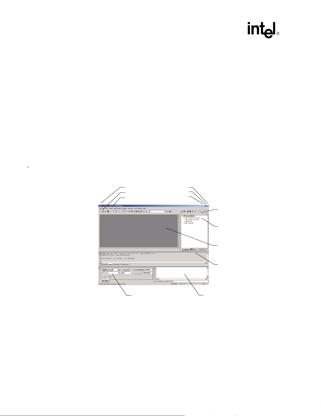
IXP2400/IXP2800 Network Processors
Developer Workbench
Developer Workbench Revision Information:
T o determine the revision:
• On the Help menu, click About Developer Workbench.
The About Developer Workbench information box appears displaying the revision of your
Developer Workbench.
2.2 About the Graphical User Interface (GUI)
The Workbench GUI (Figure 1) conforms to the standard Windows look and feel. You can do the
following:
• Dock and undock (float) windows, menu bars, and toolbars (see Section 2.2.1).
• Hide and show windows and toolbars (see Section 2.2.2).
• Customize toolbars and menu bars (see Section 2.2.3).
• Save and restore GUI customizations (see Section 2.2.3.6).
Figure 1. The Developer Workbench GUI
Title Bar
Toolbar
Menu Bar
Run Control Window Command Line Window
Close
Maximize
Minimize
2.2.1 About Windows, Toolbars, and Menus
Dockable windows contain controls and data. You can attach them to a location on the Workbench
main window or you can float them over the main window. All toolbars and menu bars are
dockable. (See Figure 2.)
Gripper Bar
Project Workspace Window
View/Edit Area
Output Window
T o float, or undock, a window or toolbar , double-click its gripper bar (see Figure 1). To restore it to
its previously docked location, double-click its title bar. You can also drag the window to a new
docking location.
20 Development Tools User’s Manual
Page 21
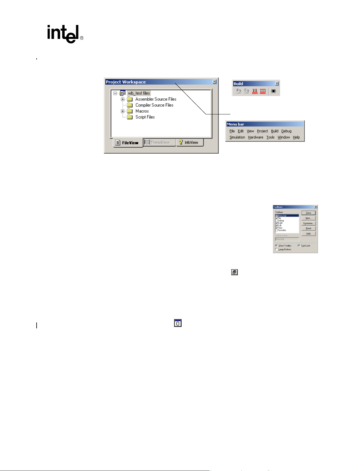
IXP2400/IXP2800 Network Processors
Figure 2. Floating Window, Tool Bar, and Menu Bar
Floating Toolbar
Title Bar
Floating Menu
2.2.2 Hiding and Showing Windows and Toolbars
Form the View menu, you can toggle the visib ili ty of the fol lowing windows in the Workbench’s
GUI:
Developer Workbench
Toolbar If you are viewing a source file, or the edit/view
area is empty, selecting Toolbar on the View
menu displays the Toolbars dialog box. Here
you can select to view or clear to hide any of the
available toolbars. You can also select Show
Tooltips, Large Buttons, and Cool Look.
Workbook Mode This control puts the tabs at the bottom of the
view/edit area (see Figure 1). Without the tabs
you must use other methods to select different
windows, such as going to the Window menu and selecting the window;
cascading the windows using the button and selecting with the
mouse pointer; pressing CTRL+F6 to switch from one window to the
next. Removing the tabs gives you more workspace in the windows.
Project Workspace See Section 2.4.
Output Window This window displays the results of Find in Files, assembly and compile
results, build results and other messages. See Figure 1.
Click the button to show or hide this window.
Debug Windows Command Line - see Section 2.13.6.
Data Watch - see Section 2.13.12.1.
Memory Watch - see Section 2.13.13.2.
History - see Section 2.13.17.6.
Thread Status - see Section 2.13.18.
Queue Status - see Section 2.13.17.
Packet Simulation Status- see Section 2.13.19
Run Control - see Section 2.13.9.
Development Tools User’s Manual 21
Page 22
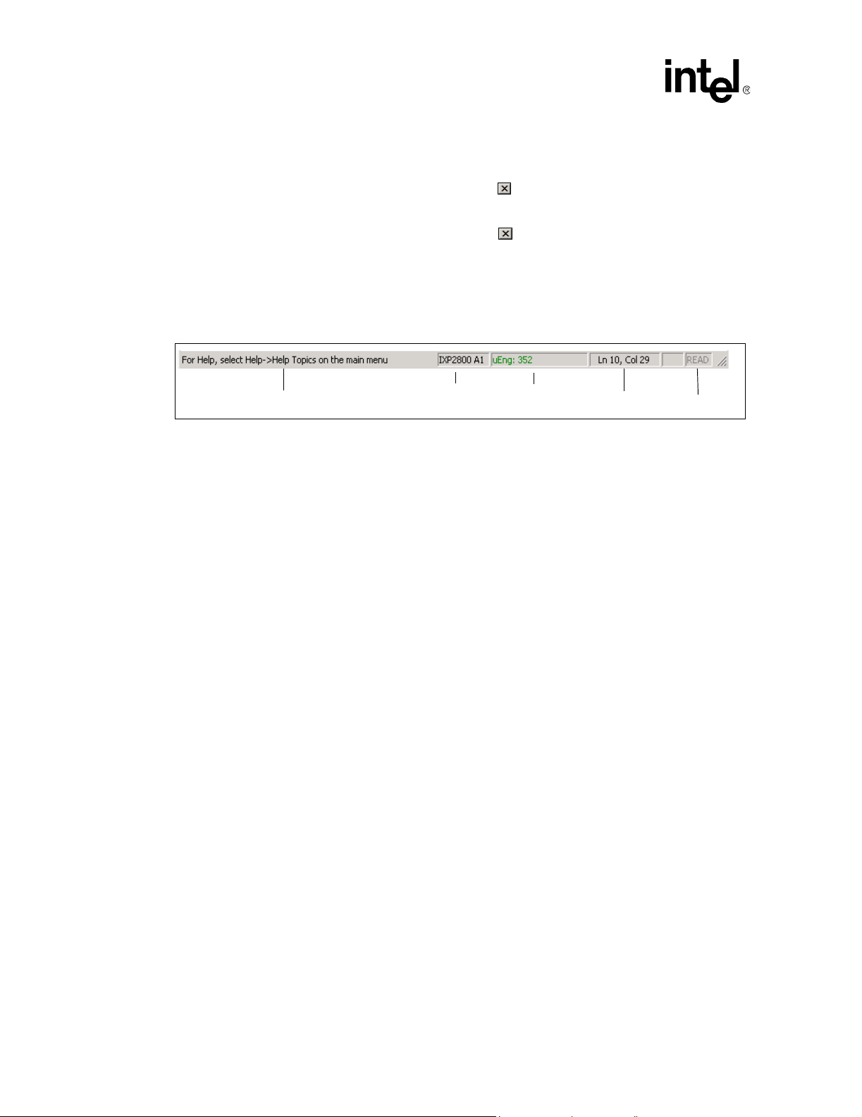
IXP2400/IXP2800 Network Processors
Developer Workbench
To toggle the visibility of a dockable window, select or clear the window’s name on the View
menu.
If a window is visible, you can hide it by clicking the button in either the upper-right or upperleft corner of the window.
If a toolbar is floating, you can hide it by clicking the button in the upper right corner.
Note: You can float and dock the GUI’s default menu bar but you cannot hide it. If you create a
customized menu bar, you can display or hide in it using the same method used for windows and
toolbars.
Stat us Bar The status bar appears at the bottom on the Workbench GUI.
General Information
General Information Information and tips appear here as you work.
Chip Type Identifies the network processor and revision (stepping).
Microengine Clock The present cycle count of the Microengine clock (simulation debug
mode only). In hardware debug mode, it shows stopped or running to
indicate microengine state.
Text Insertion Point The location of the text insertion point (cursor) by line and column.
Read-only/Write The Read/Write status of the selected file. If READ is dimmed, the status
is Read/Write.
Chip Type
Microengine clock
2.2.3 Customizing Toolbars and Menus
You can add and remove buttons from toolbars and create your own toolbars.
2.2.3.1 Creating Toolbars
To create a toolbar:
1. On the Tools menu, click Customize.
The Customize dialog box appears.
2. Click the Toolbars tab.
3. Click New.
The New Toolbar dialog box appears.
4. Type a name for the new toolbar and click OK.
Text Insertion Point
Read/Write
The toolbar name is added to the Toolbars list and the ne w tool bar appears in a floating state. If
you want the toolbar to be docked, drag it to the desired location.
T o populate the toolbar with buttons, go to Section 2.2.3.4.
22 Development Tools User’s Manual
Page 23

2.2.3.2 Renaming Toolbars
You can rename toolbars that you have created.
To rename a toolbar:
1. On the Tools menu, click Customize.
The Customize dialog box appears.
2. Click the Toolbars tab.
3. Select the desired toolbar in the Toolbars list.
4. Edit the name in the Toolbar Name box at the bottom.
5. Click OK.
Note: You cannot rename the GUI’s default toolbars (Menu bar, File, Debug, Build, Edit, View).
2.2.3.3 Deleting Toolbars
To delete a toolbar you have created:
1. On the Tools menu, click Customize.
The Customize dialog box appears.
2. Click the Toolbars tab.
IXP2400/IXP2800 Network Processors
Developer Workbench
3. Select the toolbar to delete in the Toolbars list.
4. Click Delete.
Note: You cannot delete the GUI’s default toolbars (Menu bar, File, Debug, Build, Edit, View).
2.2.3.4 Adding and Removing Toolbar Buttons and Controls
To customize the buttons on the toolbars:
1. On the Tools menu, click Customize.
The Customize dialog box appears.
2. Click the Commands tab.
3. From the Categories list, select a command category.
A set of toolbar buttons for that category appears in the Buttons area.
T o get a description of the command associated with a button, click the button. The description
appears in the Description area at the bottom of the dialog box.
4. To place a button in a toolbar, drag the button to a location on a toolbar.
5. To remove a button from a toolbar, drag the button into the dialog box.
6. Click OK when done.
Development Tools User’s Manual 23
Page 24
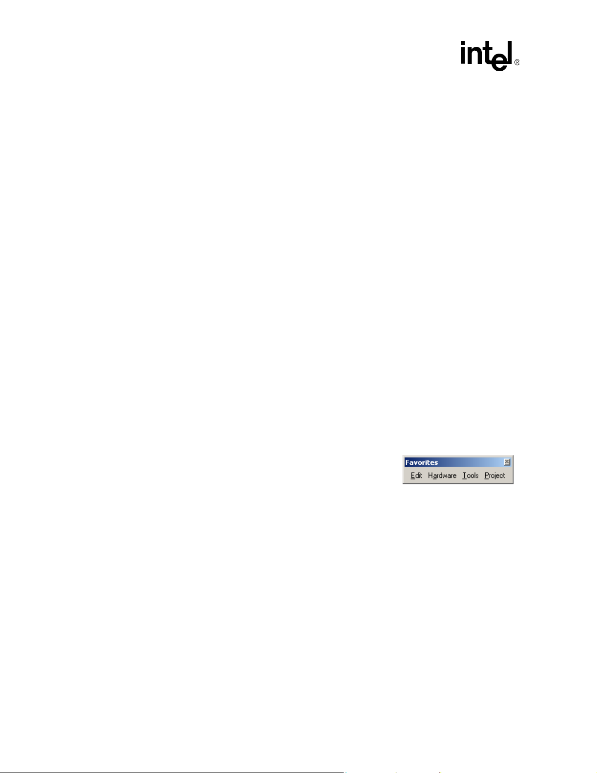
IXP2400/IXP2800 Network Processors
Developer Workbench
2.2.3.5 Customizing Menus
You can change the appearance of the main menu or you can put menus on toolbars.
Main Menu Appearance:
To change the order of the main menu items:
1. On the Tools menu, click Customize.
The Customize dialog box appears.
2. Drag any main menu item to the new position on the main menu bar. For example, drag File
and drop it after Help.
3. T o remove a menu from the main menu bar, drag it into the work area below.
4. To add a menu to the main menu bar:
a. In the Customize dialog box, click the Commands tab.
b. Click Menu in the Commands box.
All the menus appear in the Buttons box.
c. Select a menu and drag it to the main menu bar.
That menu then becomes a new menu on the main menu bar.
Menus on Toolbars:
T o put a menu on a toolbar:
1. In the Customize dialog box, click the Commands tab.
2. Click Menu in the Categories box.
All the menus appear in the Buttons box.
3. Drag any menu to any toolbar.
Note: You can put your most used or favorite menus on a floating
toolbar by creating a new toolbar (see example at right) and
dragging the menus to that toolbar.
2.2.3.6 Returning to Default Toolbar Settings
To set toolbars to their default configurations:
1. On the Tools menu, click Customize.
The Customize dialog box appears.
2. Click the Toolbars tab.
3. Select the desired toolbar and click Reset.
Only the Workbench default toolbars can be reset.
24 Development Tools User’s Manual
Page 25

2.2.4 GUI Toolbar Configurations
Build Versus Debug:
The W orkbench maintains two sets of toolbar and docking configurations, one for debug mode and
one for build, or non-debug mode. The GUI configuration that you establish while in build mode
applies only when you are in build mode. Similarly, the debug mode GUI configuration applies
only for debug mode.
Save and Restore:
Menu bar and toolbar configurations are saved when you exit the Workbench. These configurations
persist from one Workbench session to the next.
2.3 Workbench Projects
Projects may be created in two ways: standard and debug-only.
A standard project consists of one or more network processor(s), microcode source files, debug
script files, and Assembler, Compiler, and Linker settings used to build the microcode image files.
This project configuration information is maintained in a Developer Workbench project file (.dwp).
IXP2400/IXP2800 Network Processors
Developer Workbench
A debug-only project is one in which the user specifies an externally built uof file for each chip in
the project. If a project is created as “debug-only” the user does not specify assembler and compiler
source files, manage build settings, or perform uof file builds using the Workbench GUI.
When you start the workbench you can:
• Create a new project (see Section 2.3.1).
• Open an existing project (see Section 2.3.2).
• Save a project (see Section 2.3.3).
• Close a project (see Section 2.3.4).
• Specify a default folder for creating and opening projects (see Section 2.3.5).
2.3.1 Creating a New Project
The processor type, that you select when you create a new project, determines which Transactor is
used for simulation. The Wo rkbench will display only the GUI components that are relevant to the
selected processor type. The processor family cannot be changed once a project is created; i.e. you
cannot change your project from an IXP2400 processor to an IXP2800 processor, or vice versa.
The processor types supported by the workbench are:
• IXP2800 A1
• IXP2800 A2
• IXP2800 B0
• IXP2400 B0
Development Tools User’s Manual 25
Page 26
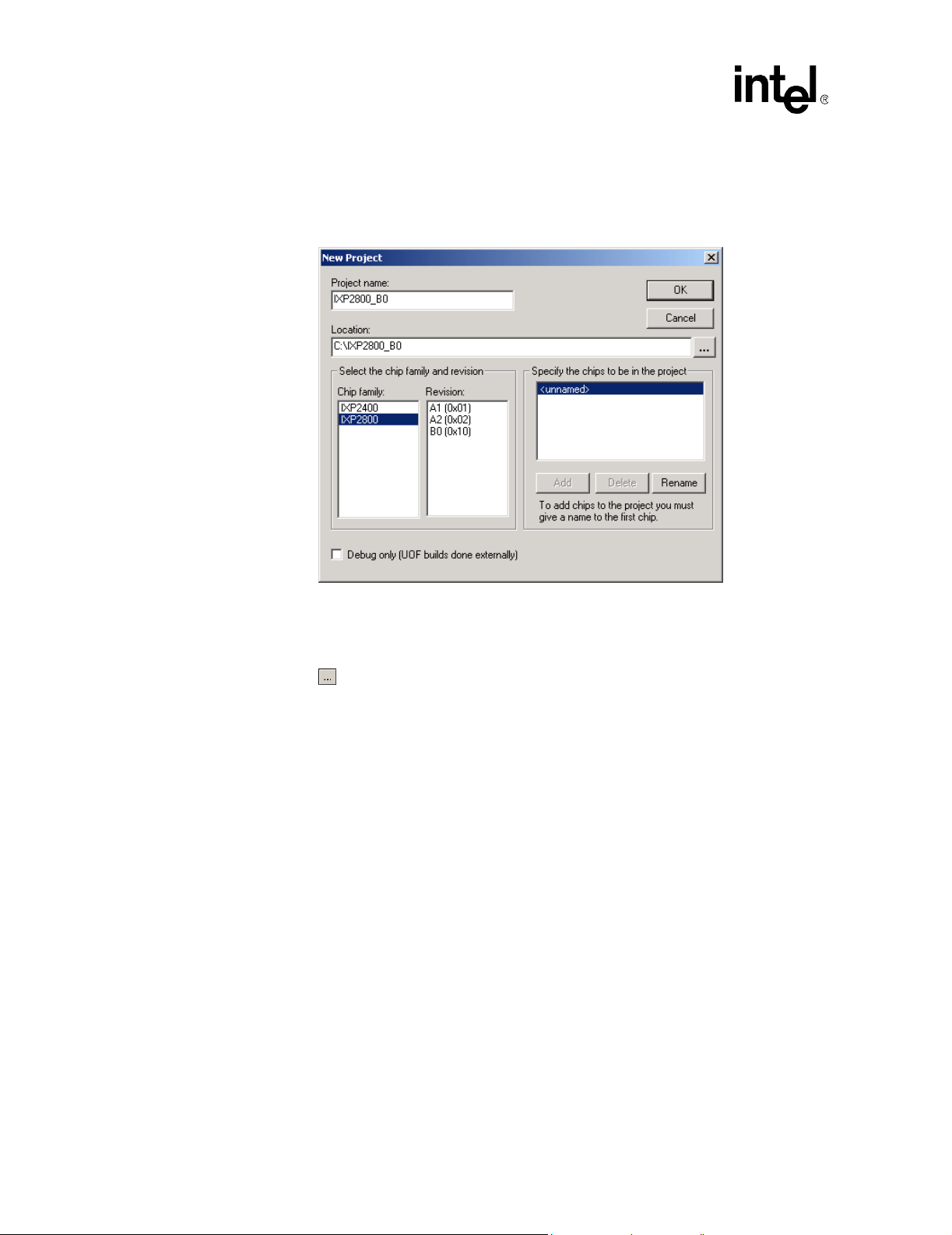
IXP2400/IXP2800 Network Processors
Developer Workbench
To create a new project:
1. On the File menu, click New Project.
The New Project dialog box appears.
2. Type the name of the new project in the Project name box.
3. Specify a folder where you want to store the project in the Location box.
If the folder doesn't exist, the Workbench creates it. You can browse to select the folder by
clicking the button.
4. Select the chip family in the Chip Family box.
5. Select the revision number (stepping) for the chip in the Revision box.
6. Specify the number of chips to be in the project in the Specify the chips to be in the project
box. Do the following:
— If you have only one chip in your project, it can be <unnamed>.
— T o specify more than one chip, they must all have unique names. You cannot add a second
chip until you have named the first chip. When you finish creating a project, you cannot
change the number of chips in it.
— To rename a chip, select the chip in the list and click Rename. The Chip Name
dialog box appears. Type the chip’s name and click OK.
— To add a chip to the configuration, click Add. The Chip Name dialog box appears.
Type the chip’s name and click OK.
— To delete a chip from the configuration, select the chip in the list and click Delete.
7. If this project is to be “debug-only”, click the Debug only check box.
This specification tells the Workbench that the source files and list files to be used in this
project will be built externally. Since the uof file contains the absolute paths of the source and
list files, you must make sure to specify the correct locations for those files. If the Workbench
cannot find the proper files, debugging will not work as expected.
26 Development Tools User’s Manual
Page 27

IXP2400/IXP2800 Network Processors
Developer Workbench
Caution: Once a project is created as Debug only, it cannot be converted to a standard, Workbench buildable
project. Neither can an existing standard project be converted to Debug only.
8. When you are finished, click OK to create the project.
The project name you typed, by default, becomes a folder containing two files—project_name.dwp
and project_name.dwo (optionally you can specify any name for this folder). From this point on,
all the project files and information defaults to this folder or one of its subfolders. For example, a
project named CrossBar has a project file named Crossbar.dwp.
Note: Creating a new project automatically closes the active project, if one is open, and asks you if you
want to save any changes if there are any.
2.3.1.1 Debug-only Projects
If you select the Debug-only option when you create the project, there are some Workbench
features that will be unavailable when you open the project.
• There are no source files available since the Workbench does not do the builds, and there is no
way to add source files to a Debug-only project. The conventional options on the Project
menu are replaced with the option Specify Debug-only UOF files.
• The Project Workspace Fileview tab does not display the tree elements Assembler Source
Files, Compiler Source Files, or Macros since the Workbench does not associate source files
with the Debug-only project.
Select Specify Debug-only UOF Files from the Project menu. When you select the Debug-only
option, the dialog box shown in Figure 3 is used to specify the uof file for each chip in the project.
If you try to start debugging without specifying a uof file, or if the uof or any list file identifi ed in
the uof file is not readable, errors will occur and debugging will not take place. If a list file cannot
be found in the location specified in the uof file, the user is prompted to browse to the correct
location for the list file. This can occur if the list file has been moved from where it was when the
uof file was created or if the build was done on a different system from the one where the
Workbench is being run.
Similarly, if the user executes a Go To Source command but the source file cannot be found in the
location specified in the uof file, the user is prompted to browse to the correct location for the list
file.
The user also has the option to delete all file paths that were saved by the Workbench, as previously
described. This may be required if the user moves the list and source files to different locations. To
delete saved file paths, click the Delete Paths button.
Development Tools User’s Manual 27
Page 28
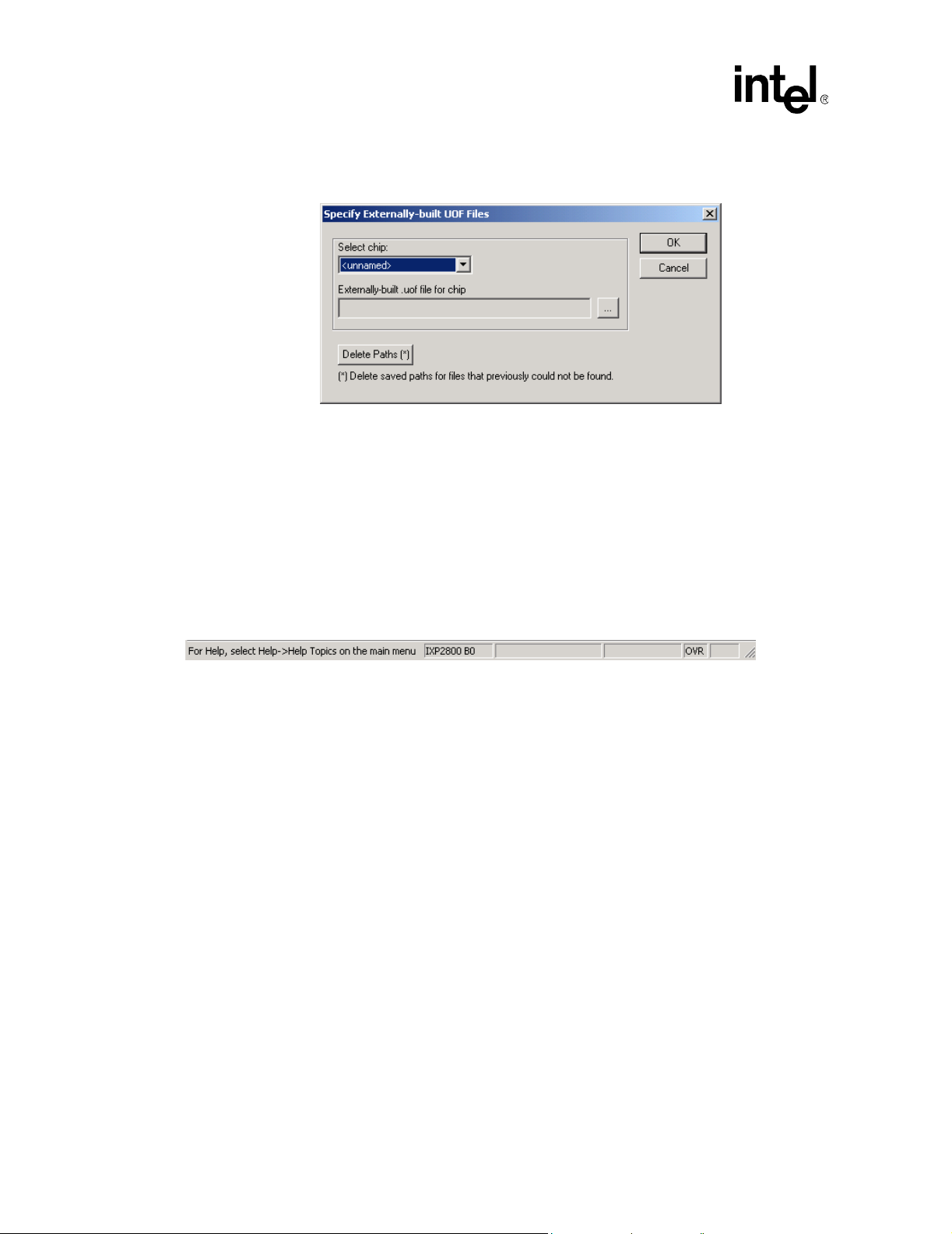
IXP2400/IXP2800 Network Processors
Developer Workbench
Figure 3. Specify Debug-only UOF Files Dialog Box
2.3.2 Opening a Project
To open an existing standard project:
1. On the File menu, click Open Project.
The Open Project dialog box appears.
2. Browse to the folder that contains the project file (*.dwp) for the project you want to open.
3. Double-click the project filename or select the project filename and click Open.
Once open, the processor type is displayed in the status bar, as shown below:
You can also select a project from the most recently used list of projects, if it is one of the most
recent four projects opened.
1. On the File menu, click Recent Projects.
2. Click the project file from the list.
Note: Opening a project automatically closes the currently open project, if any, after asking you if you
want to save changes if there are any.
2.3.3 Saving a Project
To save a modified project:
• On the File menu, click Save Project.
This saves all project configuration information, such as debug settings to the project file. If your
project hasn’t been modified, the Save Project selection is unavailable. Also, on the File menu,
click Save All to save all files and the current project.
The project is saved in the folder that you specified when you created it. If you opened an existing
project, it is saved in the folder from which that you opened it.
28 Development Tools User’s Manual
Page 29
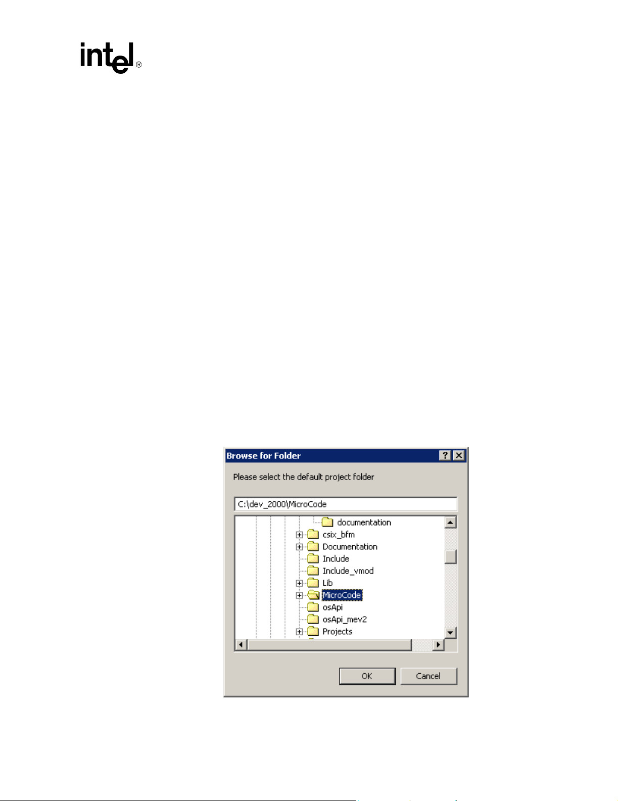
IXP2400/IXP2800 Network Processors
Note: You do not have the option of saving the project in a different folder.
2.3.4 Closing a Project
To close a project:
• On the File menu, click Close Project.
If there are any modified but unsaved files in the opened project, you are asked if you want to
save these changes.
— Click Yes to save the file and close it, or
— Click No to close it without saving any changes, or
— Click Cancel to abort closing the project.
An open project is automatically closed whenever you open another project or create a new project.
2.3.5 Specifying a Default Project Folder
You can specify a default folder for creating new projects and opening projects. When you select
Default Project Folder from the File menu, the Browse for folder dialog box appears. The
default project folder is used as the initial folder in the following cases:
Developer Workbench
• If the user selects New Project from the File menu.
• If the user selects Open Project from the File menu.
• If no project is open and the user creates a new file then selects Save As from the File menu.
• If no project is open and the user selects Open from the File menu.
Development Tools User’s Manual 29
Page 30
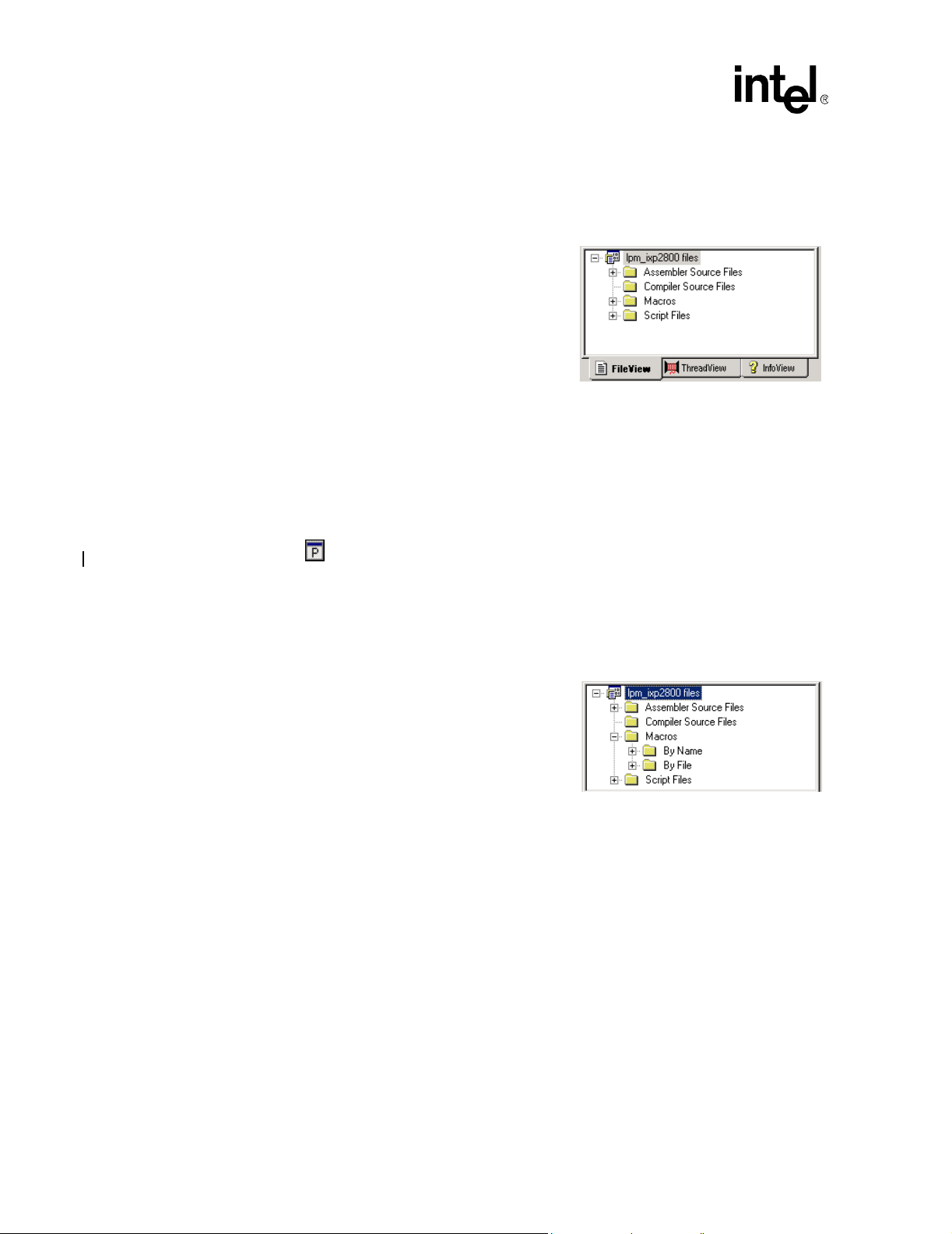
IXP2400/IXP2800 Network Processors
Developer Workbench
2.4 About the Project Workspace
The project workspace is a dockable window where you access and modify project files. It consists
of three tabbed windows:
FileView
ThreadView
InfoView
T o select a window, click its tab.
• When you start the Workbench, only InfoView is
visible.
• When a project is open, FileView and ThreadView become visible, but access to
ThreadView is unavailable.
• When you start debugging, access to ThreadView is enabled.
• When you stop debugging, access to ThreadView is disabled.
To toggle the visibility of the Project Workspace:
• On the View menu, select or clear Project Workspace, or
Click the button on the View toolbar.
2.4.1 About FileView
FileView contains a tree listing your project files. The top-level item in the tree is labeled <projectname> files. There are four second-level folders:
• Assembler Source Files, which expands to an
alphabetical list of all project Assembler source
files.
• Compiler Source Files, which expands to an
alphabetical list of all project Compiler source files.
• Macros, which expands to list the macros that are
defined in the project’s source files. This folder
expands to:
— Macros by name, and
— Macros by file.
• Script Files, which expands to an alphabetical list of all debugging script files.
30 Development Tools User’s Manual
Page 31

2.4.2 About ThreadView
ThreadView contains a tree listing all Microengines
that are loaded with microcode. ThreadView provide s access
to all enabled threads for each chip and is only available
while debugging.
The top-level item in the tree is labeled <project-name>
threads. There is a second-level item for each chip in the
project. Each chip item expands to list the Microengines in
the chip. Microengines are implemented in two clusters, 0
and 1, with a maximum of 16 Microengines in each cluster.
For the IXP2800, there are eight Microengines per cluster,
with addresses 0 - 7 and 16 - 23. For the IXP2400, there are
four Microengines per cluster, with addresses 0 - 3 and 16 -
19. The Workbench displays each Microengine name as
Microengine c:n where c represents the cluster number (0 or
1) and n is the number within the cluster.
Each Microengine item expands to list the four or eight
threads in a Microengine, but only if the threads are active in
the microcode. If a Microengine is not loaded with code, no
“+” sign appears to the left of the icon and therefore cannot be expanded to show the threads.
IXP2400/IXP2800 Network Processors
Developer Workbench
By default, a chip’s threads are named Thread 0 through Thread n.
The last thread by default varies depending on which network processor you choose:
• IXP2800 Network Processor - Thread 127
• IXP2400 Network Processor - Thread 63
2.4.2.1 Expanding and Collapsing Thread Trees
You can expand the entire tree for a chip as follows:
1. Right-click the chip name.
2. Click Expand All from the shortcut menu.
Note that in the tree to the right, Microengines 0:2, 0:3, and 0:4 cannot be
expanded because they contain no microcode.
To collapse a chip’s tree, double-click the chip name.
2.4.2.2 Renaming a Thread
You can rename a thread (to indicate its function or for any other reason). To do this:
1. Right-click the thread name in ThreadView.
2. Click Rename Thread from the shortcut menu.
The Rename Thread dialog box appears.
3. Type the new name for the thread.
4. Click OK.
Development Tools User’s Manual 31
Page 32

IXP2400/IXP2800 Network Processors
Developer Workbench
2.4.3 About InfoView
InfoView provides access to documentation as part of the Software Developer’s Kit (SDK).
To view a document, double-click its name or icon. This invokes Adobe Acrobat Reader*, which
then displays the document. A copy of Acrobat Reader is provided on the distribution CD-ROM.
2.5 Working with Files
The Workbench allows you to:
• Create files (see Section 2.5.1).
• Open files (see Section 2.5.2).
• Close files (see Section 2.5.3).
• Save files (see Section 2.5.4).
• Save copies of files (see Section 2.5.5).
• Save all files at once (see Section 2.5.6).
• Print files (see Section 2.5.8).
• Insert files into a project (see Section 2.5.9).
• Remove files from a project (see Section 2.5.9).
• Edit a file (see Section 2.5.10).
• Bookmarks, error/tags (see Section 2.5.11).
See also:
• Working with File Windows (see Section 2.5.7).
• About Find in Files (see Section 2.5.12).
• About Fonts and Syntax colors (see Section 2.5.13).
• About Macros (see Section 2.5.14).
2.5.1 Creating New Files
To create a new file:
5. On the File menu, click New, or
Click the button on the File toolbar.
The New dialog box appears.
6. Select which type of file you want to create from the list.
7. Click OK.
This creates a new document window. The name of the window in the title bar reflects the type of
file you have created.
32 Development Tools User’s Manual
Page 33

2.5.2 Opening Files
To open an file for viewing or editing, do one of the following:
• On the File menu, click Open, and select a file from the Open dialog box, or
Click the button on the File toolbar, or
If the file is in your project, double-click the file name in FileView.
In the open dialog box you can filter your choices using the Files of type: list to select a file
extension. This limits your choices to only files with that extension. If you select All files (*.*),
your choices are unlimited. You can select any unformatted text file to view or edit.
You can open any of the last four files that you have opened. To do this:
1. On the File menu, click Recent Files.
2. Select from the list of files that appears to the right.
2.5.3 Closing Files
To close an open file:
IXP2400/IXP2800 Network Processors
Developer Workbench
• On the File menu, click Close, or
On the Window menu, click Close to close the active file and its document window, or
On the Windows menu, click Close All to close all open files and their document windows.
Note: All files that have been edited but not saved are automatically saved when you perform any
operation which uses file data, such as assembling, building, updating dependencies, and finding in
files.
2.5.4 Saving Files
To save a fil e:
1. On the File menu, click Save, or
Click the button on the File toolbar.
If you have just created the new file, the Save As dialog box appears. If you are saving an
existing file, the Save dialog box appears.
2. Type the name of the new file.
3. Click OK.
This saves your work to a file when you are finished editing. It also displays the new file name in
the title bar of the window. By convention, microcode source files have the file type .uc, C
Compiler source files have the file type .c, and script files have the file type .ind.
If you are saving an existing file, you do not need to type a new name.
To save a file under a new name:
1. On the File menu, click Save As.
Development Tools User’s Manual 33
Page 34

IXP2400/IXP2800 Network Processors
Developer Workbench
The Save As dialog appears. The current name of the file appears in the File Name box.
2. Type a new name in the File Name box and click Save.
Note that the old file remains in the folder but will not have edits that you have made. The new
name appears in the title bar.
2.5.5 Saving Copies of Files
You can save a copy of a file that you are viewing or editing.
To do this:
1. On the File menu, click Save As.
The Save As dialog box appears.
2. Browse to the folder where you want to save the file.
3. Type the new name of the file in the File name box.
4. Click Save.
The Save as type list is used only if you don’t include the extension in the File name box. If you
select All files (*.*), you must include the extension in the name.
2.5.6 Saving All Files at Once
You can save all modified files in your project at once.
To do this:
• On the File menu, click Save All, or
Click the button on the File toolbar.
2.5.7 Working With File Windows
When you select a file (text, Assembler source, Compiler source, source header, or script) for
viewing or editing, it appears in a file window in the upper-left part of the Workbench. The
Windows menu deals mostly with the text file windows in the Workbench.
New Window Creates a new window containing a copy of the file in the active window .
The Title Bar displays filename.ext:2.
Close Closes the active window.
Close All Closes all the open windows.
Cascade Cascades all windows that are not minimized in the viewing area.
Tile Tiles all windows that are not minimized in the viewing area.
Arrange Icons Tiles the window icons (if minimized) at
the bottom of the viewing area.
34 Development Tools User’s Manual
Page 35

Open Windows Selection:
At the bottom of the Windows menu is a list of the first nine windows that you opened. Click any
one of these windows to make it the active window. If you opened more than nine windows, click
More Windows. From the Select Window dialog box, click the window that you want to make
active and then click OK.
Other Window Controls:
Minimize Click the button on the window that you want to minimize.
Maximize Click the button on the window that you want to maximize. You can
Close Click the button on the window that you want to close.
Restore Click the button on the minimized window that you want to restore
2.5.8 Printing Files
IXP2400/IXP2800 Network Processors
Developer Workbench
also double-click the title bar to do this.
to its previous view.
2.5.8.1 Setting Up the Printer
1. On the File menu, click Printer Setup.
The Print Setup dialog box appears.
2. Select the printer properties for your printer. They will
vary depending on the printer you select in the Name
box.
3. Click OK when done.
Setting the printer properties does not print the file. To do
this see Section 2.5.8.2.
2.5.8.2 Printing the File
You can print text files to a hardcopy printer or to a file.
To do this:
1. Make sure that the file you want to print is in the active window.
2. On the File menu, click Print, or
Click the button on the File toolbar. (This button is not on the default File menu. To put
this button there, see Section 2.2.3.4.)
The Print dialog box appears.
3. Select the printer (or printer driver) from the Name list.
4. Click Properties to customize your particular printer. Each printer has its own printer settings.
5. If you want to print to a file (*.prn), select Print to file and select a folder and file name after
you click Print.
6. Select the pages you want to print in the Print range area.
Development Tools User’s Manual 35
Page 36

IXP2400/IXP2800 Network Processors
Developer Workbench
7. Select the number of copies in the Copies area.
8. Click Print.
2.5.9 Inserting Into and Removing Files from a Project
2.5.9.1 Inserting Files Into a Project
You can insert Assembler source files, Compiler source files, and script files into a project.
To do this:
1. On the Project menu, click Insert Assembler Source File, or
Insert Compiler Source File, or
Insert Script Files, whichever is appropriate.
The corresponding dialog box appears.
2. Browse to the desired folder and select one or more files to be inserted.
3. Click Insert.
The newly inserted files are added to the list of files displayed in FileView in the corresponding
folder.
2.5.9.2 Removing Files From a Project
T o remove a file from your project:
1. In the Project Workspace, click the File View tab.
2. Right-click the file that you want to delete.
3. Click Delete on the shortcut menu, or
Select the file and then press the DELETE key.
Note: The file is removed from the project but it is not deleted from the disk.
2.5.10 Editing Files
The Workbench editor is similar to standard text editors. See Table 7 on page 290 for a list of Edit
controls.
If a file has been modified, an asterisk appears after its name in the W orkbench title bar.
2.5.10.1 Tab Configuration
To configure tab settings, select Options from the Tools menu. The dialog box shown in Figure 4
appears. The user selects the file type – Microcode assembler, Microengine C or Default – for
which the tab settings will have effect. For the selected file type, the user specifies:
• The tab size, which determines the number of space characters that equal one tab character.
• Whether or not the editor converts tab characters to spaces.
36 Development Tools User’s Manual
Page 37
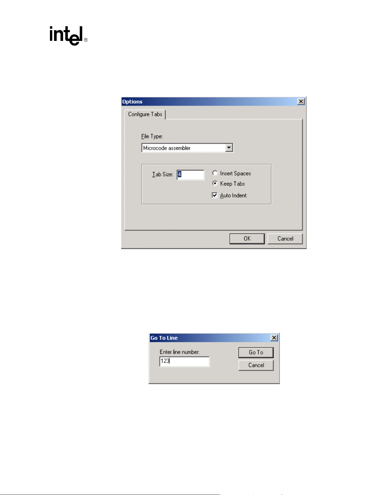
• Whether or not to auto matically indent a new line to the same column as the first non-
whitespace character in the previous line
Figure 4. Configure Tabs Dialog Box
IXP2400/IXP2800 Network Processors
Developer Workbench
2.5.10.2 Go To Line
The Workbench allows for navigating directly to a specified line within an opened document or
thread window . If the user selects Go To from the Edit menu, the dialog shown in Figure 5
appears. The user enters the desired line number and clicks Go To. The insertion cursor in the
document or thread window that currently has focus is moved to the beginning of the specified line
and the window is scrolled so that the specified line is visible.
Figure 5. Go To Line Dialog Box
Development Tools User’s Manual 37
Page 38

IXP2400/IXP2800 Network Processors
Developer Workbench
2.5.11 Bookmarks and Errors/Tags
You can mark your place in a file using
bookmarks. Table 8 lists the tools to
manipulate bookmarks in your files.
You can find errors in your files using
the Error/Tag tools listed in the tables
below.
See Table 11 for a list of Bookmark and Error/Tag controls.
Bookmarks
2.5.12 About Find In Files
The Workbench supports the ability to search multiple files for the occurrence of a specified text
string. To perform this search:
1. On the Edit menu, click Find In Files,
or
Click the button on the Edit
toolbar.
The Find In Files dialog box appears.
2. T ype the text string you want to search
for, or select from the list of previously
searched-for strings from the Find
what list.
3. Type the file types to be searched, or select from a predefined list of file types in the
In files/file types list.
This box acts as a filter on the names of files to be searched. For example, you can specify
“foo*.txt” to search only files with names that begin with “foo” and have an file extension of
“txt”.
4. Type the name of the folder to be searched in the In folder box, or select from the list of
previously searched folders in the list. You can also browse for the folder by clicking the
button to the right of the In folder box.
5. You can also select from the options:
Match whole word only Search for whole word matches only. The characters (){}[]"'<>,.?/
\;$#@!~+=-|:*&^%, plus space, tab, carriage return and line feed are
considered delimiters of whole words.
Match case Search only for strings that match the case of the characters in your
string.
Look in subfolders Search all subfolders beneath the specified folder.
Output to pane 2 Display the search results in the second output pane, labeled Find In
Files 2.
6. When you have selected all the options, click Find.
38 Development Tools User’s Manual
Page 39

IXP2400/IXP2800 Network Processors
Developer Workbench
The results of the search are displayed in the
Find In Files 1 (or 2) tab of the Output
window. For each occurrence of the search
string that is found, the file name, line number,
and line of text are displayed.
Do any of the following to display an occurrence of the search string:
• Double-click the occurrence.
• Click the occurrence and then press ENTER.
• Press F4 (the default key binding for the GoToNextTag command) to go to the next
occurrence. If no occurrence is currently selected, then the first occurrence becomes selected.
If the last occurrence is currently selected, then no occurrence is selected, or
• Press SHIFT+F4 to go to the previous occurrence. If no occurrence is currently selected, then
the last occurrence becomes selected. If the first occurrence is currently selected, then no
occurrence is selected.
In all cases, the window containing the file is
automatically put on top of the document windows. If the
file isn't already open, it is automatically opened.
The line containing the occurrence is marked with a blue
arrow.
2.5.13 About Fonts and Syntax Coloring
Source files, that is, those with file
extensions of .uc, .c or .h, appear with
syntax coloring of keywords and
comments. Keywords are words that are
reserved by the Assembler and Compiler
are used in specific context. For example,
‘alu_shf’ is reserved because it is an
Assembler instruction.
Comments comprise ‘;’ followed by text
on a line in Assembler language. By
default, keywords are colored blue and
comments are colored green.
To change color defaults:
1. Open a source file.
2. On the Tools menu, click Font and Color Settings.
The Font and Color Settings dialog box appears.
3. In the Color list box, select the item for which you want to specify a color.
At the Foreground and Background controls, the colors already selected for the item you selected
in Step 3 are displayed.
• Select Automatic to use the Window’s default colors.
Development Tools User’s Manual 39
Page 40

IXP2400/IXP2800 Network Processors
Developer Workbench
• Clear Automatic to enable the color selection controls. Then select a color for the item you
selected.
Continue this procedure for any other items that you want to change.
• To change fonts, click Choose Font to select a different font for display.
• To go back to original settings, click Reset All.
Your customized settings are saved in the UcSyntaxColoring.ini file located in the folder with
the Workbench executable.
2.5.14 About Macros
The FileView tab in the Project Workspace has a Macro folder that contains the macros that are
defined in the project’s source files.
The macros are:
• Listed alphabetically, in the By Name folder, and
• Grouped according to the file that they are defined in, in the By File folder.
The Workbench:
• Creates these folders when you open a project.
• Updates them when:
— An edited source file is saved,
— A source file is inserted into or deleted from the project, or
— You update dependencies, by selecting Update Dependencies from the Project menu.
To go to the location in the source file where a macro is defined, double-click the macro name.
If an opened source file contains a macro reference and you want to go to the file and location
where that macro is defined:
1. Right-click the macro reference.
2. Click Go To Macro Definition on the shortcut menu.
2.6 The Assembler
The Workbench contains an Assembler for your *.uc source files. The following topics on the
Assembler will help you understand:
• How root files and dependencies are determined (see Section 2.6.1).
• How to make and change Assemb ler build settings (see Section 2.6.2).
• How to invoke the Assembler (see Section 2.6.3).
• How to handle assembly errors (see Section 2.6.4).
For information on:
• Creating new files, see Section 2.5.1.
40 Development Tools User’s Manual
Page 41

• Saving files, see Section 2.5.4.
• Opening files, see Section 2.5.2.
• Editing fi les, see Section 2.5.10.
• Closing a file, see Section 2.5.3.
• Searching for text in a source file, see Section 2.5.10 and Section 2.5.12.
• Fonts and syntax colors in a source file, see Section 2.5.13.
For details, refer to the Intel
Manual.
IXP2400/IXP2800 Network Processor Programmer’s Reference
2.6.1 Root Files and Dependencies
The executable image for a Microengine is generated by a single invocation of the Assembler that
produces an output ‘.list’ file. You can place all the code for a Microengine into a single source file,
or you can modularize it into multiple source files. However, the Assembler allows you to specify
only a single filename. Therefore, to use multiple source files, you must designate a primary, or
root, file as the one that gets specified to the Assembler. You include the other files from within the
root file or from within already included files, by nesting or chaining them. The included files are
considered to be descendants of the root file. In the FileView tab of the Project Workspace, root
files are distinguished by having an to the left of it.
IXP2400/IXP2800 Network Processors
Developer Workbench
You can designate the same output file to be loaded into more than one Microengine. You can also
include the same source file under more than one root file, making the file a descendant of multiple
root files.
In order for the Workbench to build list and image files, you must assign a .list file to at least one
Microengine. You set root files as part of setting Assembler options. On the Project menu, click
Update Dependencies to have the Workbench update the dependencies for all source files in the
project. If a file is included by a source file but is not itself a source file in the project, the
Workbench automatically inserts that source file into the project. The Workbench automatically
performs a dependency update when a project is opened. When you insert a microcode file into a
project, the Workbench checks that file for dependencies.
2.6.2 Selecting Assembler Build Settings
To make or change Assembler settings:
1. On the Build menu, click Settings.
The Build Settings dialog box appears.
2. Click the General tab to specify additional include directories and the processor revision
(stepping) range (see Section 2.6.2.1).
3. Click the Assembler tab to specify parameters for creating .list files and other Assembler
options.
Note: Compiler settings on the General tab are covered in Section 2.7.2.
Development Tools User’s Manual 41
Page 42

IXP2400/IXP2800 Network Processors
Developer Workbench
2.6.2.1 General Build Settings
The following settings, on the General tab, apply to the compiler as well as the assembler.
Specifying Preprocessor Definitions:
Use the Preprocessor definitions edit box to enter preprocessor definitions that will be applied to
all microengine list file assembles and compiles in the project. After entering preprocessor
definitions on the General page, when you open the Assembler or Compiler pages you will see
that the General definitions appear in the command line just prior to any microengine-specific
settings. This means that an engine-specific preprocessor definition will override a general setting.
Specifying Processor Revision Range:
The network processors are available in different versions (steppings) with different features. You
can specify a range of revisions for which you want your microcode assembled. Section 4.1.5
covers this topic in more detail.
Do the following:
1. On the Build menu, click Settings.
The Build Settings dialog box appears.
2. Click the General tab.
3. Select the range of processor revisions on
which you want the linked code to run.
Note: Select from the Minimum revision and the Maximum revision lists. If you select no limit as the
maximum revision number then you are specifying that your microcode is written to run on all
future revisions of the processor.
2.6.2.2 Specifying Additional Include Paths
The Assembler needs to know which folders contain the files referenced in #include statements
in Assembler source files.
To do this:
1. On the Build menu, click Settings.
2. Click the General tab.
To specify additional Assembler include
directories, the following controls are provided:
• A button to specify a new path.
T ype the path name in the space provided or
use the browse button to search for it.
You must double-click the include path
listed in order to display the browse button.
42 Development Tools User’s Manual
Page 43

• A button to delete an included path from the list.
• A button to move an included path up the list.
• A button to move an included path down the list.
Absolute versus Relative Paths:
Regardless of whether the path information is entered in an absolute or relative format, it is
automatically converted to a rela tive for mat. This all ows th e proj ect t o be mo ved to ot her lo cations
on a system or to other systems without rendering the path information invalid in most instances as
long as files are maintained in the same relative locations. This path information is passed to the
Assembler so it may locate the files referenced in #include statements in the source code. It is also
used by the dependency checker for locating assembly source files in the project.
2.6.2.3 Specifying Assembler Options
T o specify Assembler options, do the following:
1. On the Build menu, click Settings.
The Build Settings dialog box appears.
2. Click the Assembler tab.
IXP2400/IXP2800 Network Processors
Developer Workbench
The .list File:
The Output to target .list file list allows you to select a .list file from the set of .list files that are
currently defined in the project. All other controls on the page are updated according to which .list
file you select in the list.
Insert file:
1. On the Assembler tab, click New.
The Insert New List File into
Project dialog box appears.
2. Select a path for the .list file.
3. Type a filename.
You cannot insert a .list file that has already been inserted into the project.
4. Click Insert List File.
This closes the dialog box and adds the new filename to the list. The file’s path appears in the
read-only Path of target .list file box. The rest of the boxes assume default values.
Delete File:
T o delete a .list file from a project, click Delete. This removes the .list file currently selected in the
list box from the project. All references to the file on the Linker page are removed. The actual .list
file, if it exists on disk, is not altered or deleted.
Development Tools User’s Manual 43
Page 44

IXP2400/IXP2800 Network Processors
Developer Workbench
Root files:
The Root File list provides a read-only list of all of the .uc and .h
files in the project. Select a file to designate it as the root file for the
.list file.
If no root file is selected, "- no root file -" (default) is displayed. If a
root file is not selected and you attempt to select another page or
close the dialog box with the OK button, a warning message
appears.
Warning Level:
Use the arrow buttons to raise or lower the Warning level numbers corresponding to the warning
level that you want to specify. For more information on warning levels, refer to Chapter 3
Assembler.
Warnings as Errors:
Select Warnings as errors to indicate to the Assembler to treat all warnings as errors.
Local Memory:
The Local Memory settings allow the user to specify the region
of local memory that is available to the assembler for allocating
local memory variables.
The Start value is a longword-aligned byte address which
specifies the start of the region. If Size is unchecked, then the
region begins at the start address and extends to the end of local memory. If Size is checked, then
the region begins at the start address and extends for the number of bytes specified in the Size field.
Produce Debug Information:
Select Produce debug info to add debug information to the output file. If you do not select this
option, you will not be able to open a thread window in debug mode.
Note: The Produce debug info switch must be set for the necessary debug information to be present in
the uof file. Unchecking the Produce debug info check box causes the size of the uof file to be
smaller at the expense of the project not being debuggable (in any fashion) through the W orkbench
Require Register Declarations:
Select Require register declarations to force the programmer to explicitly declare registers in the
Assembler source code. Undeclared registers will cause an error. The default for IXP2nnn network
processors is enabled.
Automatically Fix A/B Bank Conflicts:
Select Automatically fix A/B bank conflicts to have the Assembler try to resolve A/B bank
conflicts among registers.
44 Development Tools User’s Manual
Page 45

IXP2400/IXP2800 Network Processors
Automatically spill GPRs:
Select Automatically spill GPRs to instruct the Assembler to spill
GPR Contents to local memory in the event that there are too many
registers to fit in the available number of GPRs.
Preprocessor Definitions:
Preprocessor definitions are symbols used in
#ifdef and #ifndef statements to
conditionally assemble sections of source files.
Multiple definitions are separated by spaces.
Optionally a replacement value may be assigned
to a definition by append an "=" and a value; no
spaces can occur between the symbol name and
the "=" or between the "=" and the value. Default is blank.
Additional Assembler Options:
This control allows you to enter text that is used to
edit the command line, replacing the Edit/Override
check box used in previous releases of the
Workbench. T ext added in this control will appear in
the command line just prior to the list file.
Developer Workbench
Save Build Settings:
The Build Settings dialog box works with a copy of the build settings in the project. When you
click OK, the W orkbench validates your data and does not allow the dialog box to close if there are
any errors. Validation is independent of which page is active at the time.
You have the option to fix the errors or click Cancel if you choose not to save any changes you
have made. When the data in Build Settings passes validation, the data in the project is updated.
2.6.3 Invoking the Assembler
To assemble a microcode source file:
1. On the File menu, click Open to open the file or double-click on the file in FileView.
If the file is already open, activate its document window by clicking on the file window.
2. On the Build menu, click Assemble, or
Press CTRL+F7, or
Click the button.
Root Files:
If the file is a project source file, the Workbench assembles all list files for which that file is a root
or for which that file is a descendant of a root.
If the file is a project source file, but is not a root or a descendant of a root, or if the file is not in the
project, the W o rkbench assembles it using default assembler settings and produces a list file of the
same name with the ‘.list’ file type.
Development Tools User’s Manual 45
Page 46

IXP2400/IXP2800 Network Processors
Developer Workbench
Results:
The results of an assembly appear in the Build tab of
the Output window, which appears automatically.
You can control the amount of detail provide in the
results. On the Build menu, click Verbose Output
to toggle between getting detailed results and
summary results.
Assembly is also done as part of a build operation.
Note: You can toggle the visibility of the Output window by clicking the button on the View
toolbar.
2.6.4 Assembly Errors
Assembly errors appear in the Build tab of the Output window. Do any of the following to display
the line of source code that caused an error:
• Double-clic k the error descripti on, or
Press F4, or
Click the button.
If no error is selected, the first error becomes selected. If the last error is selected, then no error is
selected.
To go to the source line for the previous error:
• Press SHIFT+F4, or
Click the button.
If no error is selected, then the last error becomes selected. If the first error is selected, then no error
is selected.
In all cases, the window containing the source file is put on top of the document windows. If the
source file isn't open, Workbench opens it.
A blue arrow in the left margin marks lines containing errors. Only
one error at a time is marked.
Note: The default Debug toolbar does not contain these buttons. To add them, go to Section 2.2.3.4
46 Development Tools User’s Manual
Page 47

2.7 The Microengine C Compiler
The Workbench contains a C Compiler to compile C source code into microcode for the
Microengines. The Microengine C Compiler is a general purpose Compiler but the C language
used for the Microengines is limited. Refer to the Microengine C Compiler Language Support
Reference Manual for information on the functions and intrinsics designed for use with the
network processors.
The C Compiler can compile a source file (.c, .h) or an object file (.obj).
For information on:
• Creating new C source files, see Section 2.5.1.
• Saving C source files, see Section 2.5.4.
• Opening C source files, see Section 2.5.2.
• Editing C source files, see Section 2.5.10.
• Closing a C source file, see Section 2.5.3.
• Searching for text in a C source file, see Section 2.5.10 and Section 2.5.12.
IXP2400/IXP2800 Network Processors
Developer Workbench
• Fonts and syntax colors in a C source file, see Section 2.5.13.
This section details:
• Adding C source files to your project (see Section 2.7.1).
• Selecting the target .list file (see Section 2.7.2.2).
• Selecting the target .obj file to compile (see Section 2.7.2.6).
• Deleting a target .list file (see Section 2.7.2.7).
• Selecting C source files to compile (see Section 2.7.2.3).
• Selecting C object files to compile (see Section 2.7.2.4).
• Removing C source files from project (see Section 2.7.2.5).
• Selecting compile parameters (see).
— “Optimizer:”
— “Inlining:”
— “Endian Mode:”
— “Warning level:”
— “Context”
— “Produce debug information:”
— “Produce assembler source file:”
— “Preprocessor definitions:”
— “Additional compiler options:”
Development Tools User’s Manual 47
Page 48

IXP2400/IXP2800 Network Processors
Developer Workbench
2.7.1 Adding C Source Files to Your Project
After creating and saving C source files, you need to add them to your project. To do this:
1. On the Project menu, click Insert Compiler Source Files.
The Insert Compiler Source Files into Project dialog box appears.
2. From the Look in list, browse to the folder containing your C source file(s).
3. Select the file(s) that you want to insert into your project.
4. Click Insert.
In the Project Workspace window, to the left of the Compiler Source Files folder, a ‘+’ appears (if
the folder was previously empty) indicating the folder now contains files. Click the ‘+’ to expand
the folder and display the files. You should see the files that you have just added to your project.
2.7.2 Selecting Compiler Build Settings
Before building your project, you must select your C Compiler options.
Note: General build settings are detailed in Section 2.6.2.1.
2.7.2.1 Selecting Additional Compiler Include Paths
The C Compiler needs to know which areas of the file system to search for locating files referenced
in #include statements in C source code files. This control displays a list of paths with a GUI for
typing in or editing of directory paths, or browsing to directories to be added to the list. The GUI
also provides the means for deleting or changing the search order of the paths.
Regardless of whether the path information is entered in an absolute or relative format, it is
automatically converted to a relative format. This allows the project to be moved to other locations
on a system or to other systems without rendering the path information invalid in most instances, as
long as the relative location of the paths is maintained. This path information is passed to the
Assembler so it may locate the files referenced in #include statements in the source code. It is also
used by the dependency checker for locating C source files in the project.
To specify additional Compiler include
directories:
1. On the Build menu, click Settings.
2. In the Build Settings dialog box, click the
General tab (if not already selected).
The following controls are provided:
• A button to specify a new path.
Type the path name in the space provided or use the button to search for it. You must
double-click the include path listed in order to display the browse button.
• A button to delete an included path from the list.
• A button to move an included path up the list.
48 Development Tools User’s Manual
Page 49

• A button to move an included path down the list.
2.7.2.2 Selecting the target .list File
When you compile your C source file, the result can become a .list file. You must select the name
of the .list file.
To do this:
1. On the Build Settings dialog box, click the Compiler tab.
2. To change the settings for a previously created .list file, select the name of the .list file from the
Output target .list and .obj files list.
3. To create a new .list file, click New .list file.
The Insert New List File into Project dialog box appears.
a. In the Look in list, browse to the folder where you want to store the .list file.
b. Type the file name in the File name box.
c. Click Insert List File.
The path of the target .list file box is a read-only text field displaying the absolute path of the target
.list file. If this path is not correct, click New again and select a new path.
IXP2400/IXP2800 Network Processors
Developer Workbench
2.7.2.3 Selecting C Source Files to Compile
The C Compiler in the Workbench can compile one or more C source files into one .list file. You
must select the source files that you want to compile. To do this:
1. In the Build Settings dialog box, click the Compiler tab.
2. Click Choose source files.
The Compiler Sources dialog box appears. The files displayed
here are all the *.c files in your project, that is all the files in the
Compiler Source Files folder in the Project Workspace
window.
3. Click the file(s) that you want to compile.
Clicking the file once selects the file and clicking a selected file
deselects it.
4. Click the button to move the selected files from the left
window to the right window.
You can select any file(s) in the right window and move them
back to the left window by clicking the button.
5. Click OK when done.
In the Source files to compile box is a list of C source files that you selected to compile.
Development Tools User’s Manual 49
Page 50

IXP2400/IXP2800 Network Processors
Developer Workbench
2.7.2.4 Selecting C Object Files to Compile
The C Compiler in the Workbench can compile
one or more C object files into one .list file.
Y ou must select the object files that yo u want to
compile. To do this:
1. On the C Compiler tab, click Choose
object files.
The Object file to include... dialog box
appears.
2. Enter the absolute path of any external
object files you want to include in the build
in the External .obj files... box.
3. Use the arrows to select or deselect any of
your project object files you want to
compile.
2.7.2.5 Removing C Source Files to Compile
T o remove any file:
1. Click the desired file in the Source files to compile list.
2. Click the button.
This removes the file from the compilation but not from the project.
2.7.2.6 Selecting the Target .obj File
You can compile your C source file to create an .obj file rather than a .list file.
To do this:
1. In the Build Settings dialog box, click the Compiler tab.
2. Click New .obj file.
The Compiler - .obj target dialog box appears.
a. In the Select project C source file list, select the name of the .c
file you want to compile.
In the .obj target file name box, the source file you selected
above appears with an .obj extension. You can change the
name of this file if you like. By default, the .obj file that you are creating goes into the
current project folder. If you want to place this file into another folder:
1: Click the Browse .obj path button.
2: Select a new folder.
b. Click OK when done.
50 Development Tools User’s Manual
Page 51

2.7.2.7 Deleting a Target .list or .obj File
To delete a target .list or .obj file from the project:
1. Select the file from the list in the Output to target .list and .obj files box.
2. Click Delete.
Note: This removes the file from the project but does not delete it from the disk.
2.7.2.8 Selecting Compile Options
In the Compiler Options box, select:
Optimizer:
None (debug) Turns off optimizations for better code troubleshooting.
Size (default) Compiled for smallest memory footprint. Speed may be
sacrificed.
Speed Compiled for fastest instruction execution. Size may be
sacrificed.
IXP2400/IXP2800 Network Processors
Developer Workbench
Local memory start:
0 (default) Determines the region in local memory where the
Compiler can allocate variables. The region starts
at the address you specify and extends to the end of local memory.
Spill sequence:
Determines the algorithm used by the
Compiler for spilling register contents to memory
Inlining:
None No inlining is done, including functions explicitly
tagged in the source code with the inline specifier.
Explicit (default) Only functions tagged with the inline specifier are
inlined. Any function that could be inlined by the
Compiler but not having this tag is not inlined.
Auto All functions with the inline tag and all other functions
thought by the Compiler to be inlinable are inlined.
Endian Mode:
Little Endian Compile in little-endian mode.
Big Endian (default) Compile in big-endian mode.
Neighbor mode:
Neighbor Writing to a neighbor register will write to the
neighbor register in the adjacent Microengine.
Development Tools User’s Manual 51
Page 52

IXP2400/IXP2800 Network Processors
Developer Workbench
Self Writing to a neighbor register will write to the neighbor register in the
Warning level:
0 Print only errors.
1, 2, or 3 (default) Print only errors and warnings.
4 Print errors, warnings, and remarks.
Context
Mode Specify whether the Microengine is configured to have
Number Select the number of contexts that you want to be
Produce debug information:
Select (default) Produces debug information in the .list file. This
same Microengine as the one executing the instruction.
4 or 8 contexts in use.
active in the Microengine (1 through 8). All others are
killed.
information is needed for many of the debugging
features of the Workbench.
Clear No debug information is compiled into the .list file.
Note: The Produce debug info switch must be set for the necessary debug information to be present in
the uof file. Unchecking the Produce debug info check box causes the size of the uof file to be
smaller at the expense of the project not being debuggable (in any fashion) through the W orkbench
Produce assembler source file:
Select Produces an assembly code file (*.uc).
Clear (default) Does not produce an assembly code file.
Allow mixed C and assembler source files:
Select Allows the user to select both C and MicroCode project files instead of
only C files. The compiler is invoked with the “-uc” switch to indicate
that the compiler should automatically invoke the assembler after
generating the microcode. The -FA”path\filename.ext” switch is used to
specify the name of the generated assembler source file. The filename
chosen by the Workbench is always the same path and filename as the
LIST file, but with a file extension of “.ucg” instead of “.list”.
Clear (default) Allows only C files to be selected.
Preprocessor definitions:
This is a text edit box where you type symbols used in #ifdef and #ifndef
statements to conditionally compile sections of Assembler sources.
Multiple definitions are separated by spaces. Optionally a replacement
value may be assigned by appending an “=” and a value. There can be
not spaces between the symbol name and the “=” or between the “=” and
the value. The default is blank.
52 Development Tools User’s Manual
Page 53

Additional compiler options:
Here you can enter additional command line options that can not be
implemented by normal GUI controls. See Chapter 5, “Microengine C
Compiler” for complete list of options.
2.7.2.9 Saving Build Settings
The Build Settings dialog box works with a copy of the build settings in the project. When you
click OK, the W orkbench validates your data and does not allow the dialog box to close if there are
any errors. Validation is independent of which page is active at the time. You have the option to fix
the errors or click Cancel if you choose not to save any changes you have made. When the data in
Build Settings passes validation, the data in the project is updated.
2.7.3 Invoking the Compiler
To compile a C source file:
1. On the File menu, click Open, or
You can also double-click the file in FileView. If the file is already open, activate its document
window by clicking on the file window.
2. On the Build menu, click Compile, or
Press CNTRL+SHIFT+F7, or
IXP2400/IXP2800 Network Processors
Developer Workbench
Click the button on the Build toolbar.
Results:
The results of an assembly appear in the Build tab of the Output window, which automatically
appears.
You can control the amount of detail provide in the results. On the Build menu, select Verbose
Output to display detailed results, or clear it to display summary results.
Compilation is also done as part of a build operation.
2.7.4 Compilation Errors
Compiler errors appear in the Build tab of th e Output window . To locate the error in the source
file:
• Double-click the error description in the Output window, or
Click the error description, then press ENTER.
You can press F4 or click the button to go to the next error. If no error is selected in the Output
window, the first error becomes selected. If the last error is selected, then no error is selected, or
You can press SHIFT+F4 or click the button to go to the previous error. If no error is selected in
the Output window, the last error becomes selected. If the first error is selected, then no error is
selected.
Development Tools User’s Manual 53
Page 54

IXP2400/IXP2800 Network Processors
Developer Workbench
In all cases, the window containing the source file is put on top of the document windows and
becomes the active document. If the source file isn't already open, it opens.
A blue arrow in the left margin marks lines containing errors. Only one error at a time is marked.
2.8 The Linker
The Linker takes the Assembler or Compiler output (.list files) on a per-Microengine basis and
generates an image file for all the Microengines specified.
2.8.1 Customizing Linker Settings
T o customize your build configuration:
1. On the Build menu, click Settings.
The Build Settings dialog box appears.
2. Click the Linker tab to view the Linker settings.
3. Customize the Linker settings (see Section 2.8.1).
4. Click OK.
The Linker page provides an interface for selecting options for the Linker and directing the
packaging of one or more Microengine specific *.list files into a *.uof file. Each chip has several
Microengines that can each be loaded with execution code according to the *.list file selected for
that Microengine.
You can also specify the assembly options by clicking the Assembler tab and the C Compiler tab
in the Build Settings dialog box.
Chip
The Chip box contains a list of all the Network Processor chips in
your project. Select the chip for which you want to change Linker
settings. The other controls on the page are updated based on the
selected chip.
Output to target .uof file
The Output to target .uof file box displays the .uof file that the
Linker produces.
Note: The Developer Workbench does not support multiple .uof files.
To change the output *.uof file to the project for the selected chip:
1. Click the button.
The Select Name and Location for the Linker Output File dialog box appears.
2. In the Look in box, browse to the folder where you want to put the output file.
3. Type a new name in the File name box.
54 Development Tools User’s Manual
Page 55
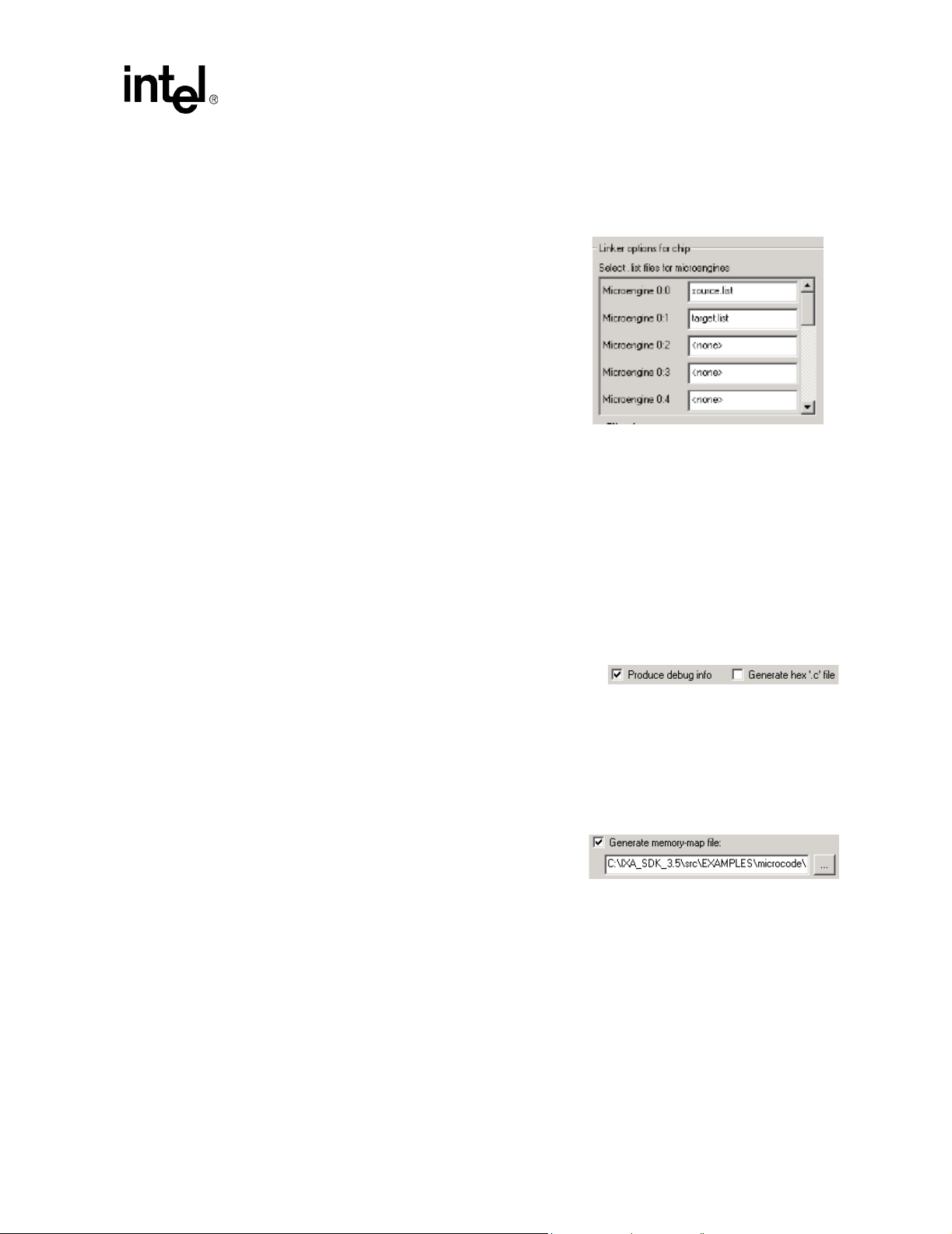
IXP2400/IXP2800 Network Processors
Developer Workbench
You do not have to type the .uof extension—the Workbench adds it for you. Typing it does no
harm.
4. Click Select.
Microengine .list file selection
The project has one or more .list file(s) generated
using the Assembler or Compiler. On the Linker page
you can control which .list file is linked into the .uof
file and for which Microengine.
To do this:
1. Click the list box to the right of Microengine 0:0.
A scrollable list of list files is displayed.
2. Select either:
a. <none>, or
b. Any .list file from list.
3. Do the same for remaining Microengines.
This method allows you to select any combination of .list files or no .list file for any or all the
Microengines to be linked to the .uof file.
If you specify <none>, no microcode gets loaded into that Microengine. If you select <none> for
all the Microengines, you get an error.
Produce debug information
Select Pr oduce debug info to add debug information to the
output file. If you do not select this option, you will not be
able to open a thread window in debug mode.
Note: The Produce debug info switch must be set for the necessary debug information to be present in
the uof file. Unchecking the Produce debug info check box causes the size of the uof file to be
smaller at the expense of the project not being debuggable (in any fashion) through the Workbench
Generate memory-map file
Select Generate memory-map file to have the
Workbench pass the -map option switch to the linker to
generate a .map file. The file contains the symbols and
their addresses. The edit control allows the user to
specify the filename or browse to it.
Hex “.c” files
Select Generate hex ‘.c’ file to request the Linker to create a *.c file, with the same name as the
corresponding *.uof file. This file contains a microcode listing in a form that can be included in a
processor core application. This is usually done when deploying microcode into a final product.
Development Tools User’s Manual 55
Page 56

IXP2400/IXP2800 Network Processors
Developer Workbench
Unused microstore
Unused microstore can be initialized by using the controls
in the Fill options for unused microstore area.
T o leave the unused microstore unchanged, select Do not
fill.
To fill the unused microstore:
1. Select Fill with default pattern (0xe000010000).
0xe000010000 for the IXP2400, IXP2800 network processors.
or
2. Click Fill with custom pattern and type a 10 character hex pattern to be used. Make sure the
number begins with “0x.”
Reserved memory segment for variables
The reserved memory segment for variables provides the Linker with information needed for
allocating memory to be used for variable data storage.
Scratch offset
The Scratch offset is a parameter sent to the Linker . The Linker uses scratch memory starting at the
base address, allocating as much memory as needed up to the Scratch offset size for variables.
Scratch segment size (bytes)
The Scratch segment size is a parameter sent to the Linker. The Linker reserves as much scratch
memory as necessary for variables up to the segment size.
SRAM offset
The SRAM offset is a parameter sent to the Linker. The Linker uses scratch memory starting at the
base address, allocating as much memory as needed up to the SRAM segment size for variables.
SRAM segment size (bytes)
The SRAM segment size is a parameter sent to the Linker. The Linker reserves as much SRAM as
necessary for variables up to the segment size.
DRAM offset
The DRAM offset is a parameter sent to the Linker. The Linker uses DRAM memory starti ng at the
base address, allocating as much memory as needed up to the DRAM segment size for variables.
DRAM segment size (bytes)
The DRAM segment size is a parameter sent to the Linker. The Linker reserves as much DRAM as
necessary for variables up to the segment size.
56 Development Tools User’s Manual
Page 57

Header file generation
Selecting Generate a header file causes the Linker to produce a C language *.h file with the same
filename as the linked *.uof file. The defined symbols are set to values based on how the Linker
allocated memory for the reserved memory variables. The base address symbols should have the
same values as the ones defined in the GUI, but the size symbols have the actual sizes used by the
Linker.
Saving settings
Linker settings are saved when you save the project.
The Build Settings dialog box works with a copy of the build settings in the project. When you
click OK, the W orkbench validates your data and does not allow the dialog box to close if there are
any errors. Validation is independent of which page on Build Settings is active at the time. You
have the option to fix the errors or click Cancel if you choose not to save any changes you have
made. When the data in Build Settings passes validation, the data in the project is updated.
2.8.2 Building and Rebuilding a Project
Building a project
• On the Build menu, click Build, or
IXP2400/IXP2800 Network Processors
Developer Workbench
Click the button on the Build toolbar, or
Press F7.
The results of the build appear in
the Build tab of the Output
window, which appears
automatically. You can control the
amount of detail provide in the
results. On the Build menu, click
Verbose Output to toggle
between getting detailed results and summary results.
Stopping
There is no way to stop a build in progress. You must wait until it finishes or encounters an error.
Out-of-date files
To perform a link, the Workbench requires that all .list files be up to date. If any microcode or
compiler source file is newer than the list file generated from it, or if Assembler or Compiler
settings have been changed since the last build, the Workbench automatically assembles or
compiles a new .list file.
Rebuilding a project
To force the assembling or compiling of all sources, regardless of whether the list files are up to
date:
• On the Build menu, click Rebuild, or
Click the button on the Build toolbar, or
Development Tools User’s Manual 57
Page 58

IXP2400/IXP2800 Network Processors
Developer Workbench
Press Alt + F7.
2.9 Configuring the IXP2400 Simulation Environment
T o configure the simulation environment for an IXP2400 project, select System Configuration
from the Simulation menu. You can set or change configuration values in the following property
pages depending on the Chip Family you have selected:
• Clock frequencies - see Section 2.9.1
• Memory - see Section 2.9.2
• MSF Devices - see Section 2.9.3
• Network Connections - see Section 2.9.4
• CBUS Connections - see Section 2.9.5
The contents of each dialog depends on the processor type defined for the project. This
configuration data is passed to the Transactor and device models through the command line
interface when you start debugging.
2.9.1 IXP2400 Clock Frequencies
Depending on the processor type defined for the project the Clock Frequencies property page will
(see Figure 6) display different default values. The values that you specify on this property page are
passed to the Transactor using the set_clocks() console function.
• Clock frequencies are set independently for each chip in the project.
• In the PLL output frequency combo box, you may currently select the PLL output frequency
of 1200 MHz.
• The Derived frequencies group box is for information only and displays the frequencies for
the Microengines and Intel XScale
frequency using fixed divisors and they cannot be modified.
• The Programmable frequencies group box contains selectable values for the two SRAM
channels and DRAM. These frequencies are programmable as a fixed set of ratios of the PLL
output frequency. These ratios correspond to fields in the Clock Cont rol CSR, which is
displayed for reference only.
• In the External frequencies group box, the MSF unit is externally clocked. Select either
Single or Dual mode clocking for receive and transmit interfaces. If you select Single mode,
only one clock value can be specified; the other control is disabled. Ratios correspond to fields
in the MSF Clock Control CSR, which is displayed for reference only.
• The PCI unit is always externally clocked. Select either 33 or 66 MHz from the scroll values.
The values shown in the following figure are the default values. The complete description of clock
frequencies, ratios, can be found in the Intel
Manual. The Clock and MSF CSRs can be found in the Intel
Processor Programmer’s Reference Manual.
®
core. These frequencies are derived from the PLL output
IXP2400 Network Processor Hardware Reference
IXP2400/IXP2800 Network
58 Development Tools User’s Manual
Page 59

Figure 6. Clock Frequencies for the IXP2400
IXP2400/IXP2800 Network Processors
Developer Workbench
2.9.2 IXP2400 Memory
The Memory tab on the System Configuration property sheet supports the configuration of
simulator memory (see Figure 7). There are some variations on the screen depending on which
network processor is being configured. For the IXP2400 the following simulator conditions apply:
• No SRAM channel can exceed 64 MB, so the Part count option of 2 becomes unavailable if
the Part size is 64.
• The simulator must have a populated SRAM channel. Zero memory cannot be configured,
therefore there is no option for a zero Part size or Part count.
There are two channels available for configuring the IXP2400 SRAM memory.
• The DRAM size is currently limited to 64 MB by the simulator, so there is only one DRAM
size option available. Channel count is unavailable for the DRAM.
• Each of the two SRAM channels may be configured indepen dentl y.
Development Tools User’s Manual 59
Page 60

IXP2400/IXP2800 Network Processors
Developer Workbench
Figure 7. IXP2400 Memory Options
60 Development Tools User’s Manual
Page 61

IXP2400/IXP2800 Network Processors
2.9.3 IXP2400 MSF Device Configuration
The MSF Device Configuration tab on the System Configuration property page supports the
configuration of media and switch fabric interfaces (see Figure 8).
You have the following options on this tab:
• Create Device...
• Edit Device...
• Delete Device
• Edit Port...
If no device is currently configured, only the Create Device... button will be available. The Delete
Device and Edit Port... buttons become active when devices are configured for selection.
Figure 8. IXP2 40 0 MSF De vi ce Con fi g urati on
Developer Workbench
Device Creation
To create a device:
1. Click Create Device...
The Create Media Bus Device dialog box appears. (see Figure 9.)
Development Tools User’s Manual 61
Page 62

IXP2400/IXP2800 Network Processors
Developer Workbench
2. Select the device type from those available on the Select device type... scrolling list.
Supported device types for IXP2400: SPHY, x32MPHY4, x16MPHY32, x32MPHY32, and
CS1X. The IXP2400 architecture also supports connecting two devices with different
restrictions.
The Device parameters and Default port parameters areas will display default values once
you select the device type.
Figure 9. The Create Me dia Bu s De vi ce Dial og Bo x for CSIX
62 Development Tools User’s Manual
Page 63

IXP2400/IXP2800 Network Processors
Figure 10. The Create Media Bus Device Dialog Box for x32MPHY16
Developer Workbench
The Default port parameters section is divided into Receive and Transmit areas. You may edit
these characteristics, which are:
Data rate (Mbits/sec) Specifies the rate at which data is taken from the network and inserted
into the port’s receive (Rx) buf fer and the rate at which data is taken from
the port’s transmit (Tx) buffer and put onto the network.
Receive buffer size Specifies the number of bytes in the receive buffer. The receive buffer
holds the data received from the network until the Network Processor
reads it from the port.
Receive threshold Specifies number of bytes that must be in the port’s receive buffer in
order for the port to signal the Network Processor that it can select the
port and request data from it.
Transmit buffer size Specifies the number of bytes in the transmit buffer. The transmit buffer
holds the data transmitted by the Network Processor until it is
transmitted onto the network.
Development Tools User’s Manual 63
Page 64

IXP2400/IXP2800 Network Processors
Developer Workbench
Low water mark See High water mark, below.
High water mark If flow control is enabled, the high water mark is used to determine if the
Interpacket gap (nsec) Specifies the amount of time between packets when receiving packets
Number of bytes the device strips from end of packet
Number of bytes of zeros the device appends to packet
device is “Hungry” or “Satisfied”. If the number of bytes in the Tx buffer
is between the low and high water marks, then the device tells the
network processor that it is Hungry. If the number of bytes is above the
high water mark, then the device tells the network processor that it is
Satisfied.
from and transmitting packets to the network.
Specifies the number of bytes that the device must strip from the end of
each received packet before the packet is passed to the Network
Processor. For example, for POS IP packets , the trailing checksum bytes
are normally stripped.
Specifies the number of bytes of zeroes the device appends to the packet
before it is transmitted by the Network Processor.
Number of extra bytes Specifies the number of bytes that are stripped from the beginning of the
packet before it reaches the device and appended to the beginning of the
packet after it leaves the device, for example the Ethernet preamble.
Note that no bytes are actually stripped or appended to the packet data.
Instead, the number of extra bytes are added into the calculation of data
rate at the network.
Device Removal:
To remove a device from the project:
1. On the Simulation menu, click System Co n figuration, then click the MSF Devices tab.
The MSF Devices property sheet appears.
2. Select a device that you want to remove. Previously created devices appear in the list box
under the Create button. You can select one by clic kin g anywhere in the row listing.
3. Click Delete Device.
Port Characteristics Edit:
To edit an individual port’s characteristics:
1. On the Simulation menu, click System Co n figuration, then click the MSF Devices tab.
The MSF Devices property sheet appears.
2. In the Port section of the property sheet, select the port that you want to modify , click the Edit
Port ... button, and the Edit Port dialog opens (see Figure 11).
3. When you have finished editing the port, click OK.
Any changes that you have made now appear in the corresponding column of the edited port.
64 Development Tools User’s Manual
Page 65

Figure 11. Port Characteristics Edit Port Dialog Box
IXP2400/IXP2800 Network Processors
Developer Workbench
2.9.4 IXP2400 Network Connections
After you have configured the packet simulation with devices and ports and created or imported
data streams, you need to specify the connections to the media/switch fabric for each chip in your
project.
1. On the Simulation menu, click System Configuration, then click the Network Connections
tab.
The Network Connections property page appears. The page is divided into two sections:
Receive side connection and Transmit side connection.
2. Select the chip to which you want to make connections in the Specify connections for chip
combo box.
3. When you have finished click OK.
If No Connection is selected, then the simulation runs without anything conn ected to that side of
the MSF.
In multi-chip projects, the receive side can be connected to the transmit side of another chip in the
project by selecting Connect to transmit side of chip. The user must select which chip and what
protocol to use for the connection. For the IXP2400, the protocols are POS3 and CSIX. Similarly,
the transmit side can be connected to the receive side of another chip in the project by selecting
Connect to receive side of chip.
To connect a device to either side, the user selects Connect to device then selects the desired
device in the combo box. Note that because a device can only be connected once, if it is selected
for a connection then the Workbench removes it as a choice for all other connections.
Development Tools User’s Manual 65
Page 66
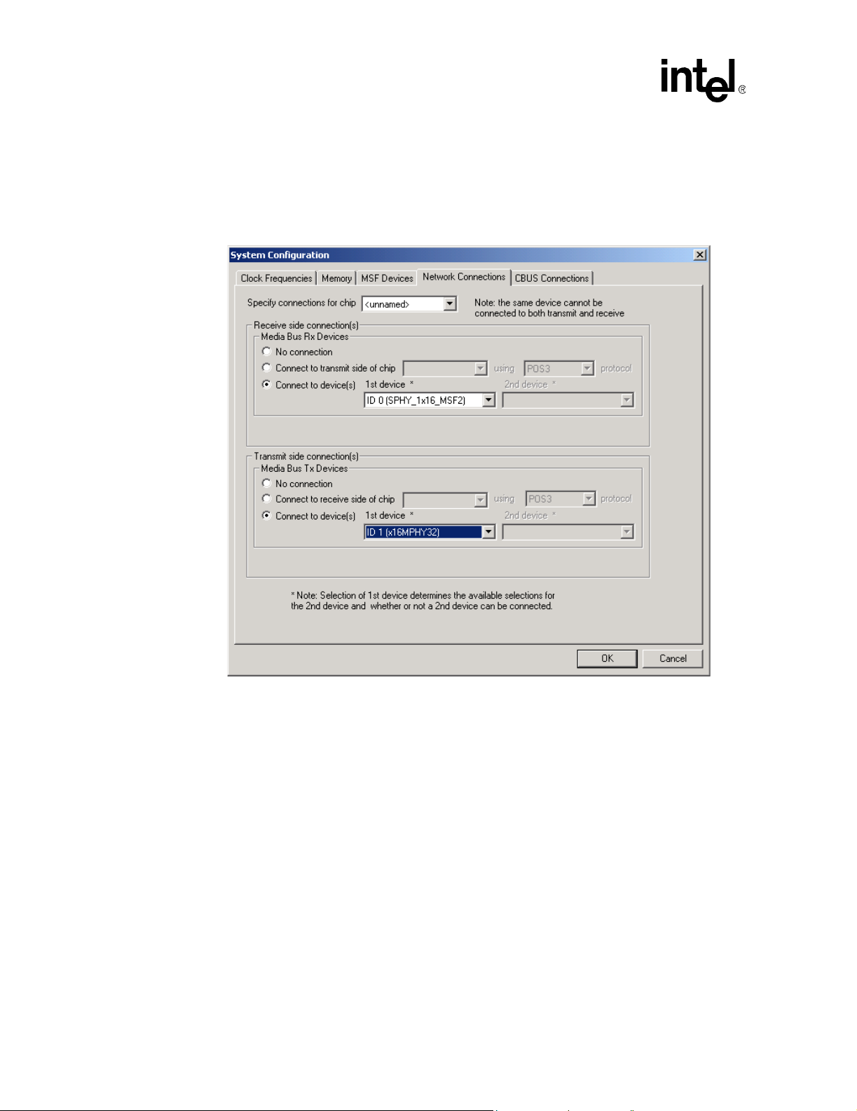
IXP2400/IXP2800 Network Processors
Developer Workbench
For the IXP2400, the Workbench displays the property page shown in Figure 12. When two
devices are connected, the 32-bit bus is considered to be split into two 16-bit busses – a lower and
an upper bus. Only an x16MPHY32 device can be connected to the lower bus and only an SPHY
device with 1x16 or 2x8 bus mode can be connected to the upper bus
Figure 12. Network Connections Property Page - IXP2400
.
66 Development Tools User’s Manual
Page 67

2.9.5 IXP2400 CBUS Connections
After you have configured the packet simulation with devices and ports and created or imported
data streams, you need to specify the connections to the media/switch fabric for each chip in your
project.
1. On the Simulation menu, click System Configuration, then click the CBUS Connections
tab.
The CBUS Connections property page appears. The page contains a check box to enable
connections using the CBUS. When you select Connect using the CBUS the receive (ingress)
and transmit (egress) pull down boxes are active.
2. Select the chip to which you want to make connections in the pull down boxes.
3. When you have finished click OK.
Figure 13 displays the CBUS Connections property page.
Figure 13. CBUS Connections Property Page - IXP2400
IXP2400/IXP2800 Network Processors
Developer Workbench
Development Tools User’s Manual 67
Page 68

IXP2400/IXP2800 Network Processors
Developer Workbench
2.10 Configuring the IXP2800 Simulation Environment
To configure the simulation environment, select System Configuration from the Simulation
menu. Y ou can set or change configuration values in the following property pages depending on the
Chip Family you have selected:
• Clock frequencies - see Section 2.10.1
• Memory - see Section 2.10.2
• MSF Devices- see Section 2.10.3
• Network Connections - see Section 2.10.4
• CBUS - see Section 2.10.5
The contents of each dialog depends on the processor type defined for the project. This
configuration data is passed to the Transactor and device models through the command line
interface when you start debugging.
2.10.1 IXP2800 Clock Frequencies
Depending on the processor type defined for the project the Clock Frequencies property page will
display different default values (see Figure 14 ). The values that you specify on this property page
are passed to the Transactor using the set_clocks() console function.
• Clock frequencies are set independently for each chip in the project.
• In the PLL output frequency group box, select the PLL output frequency: Supported
frequencies are 1600, 2000, and 2800.
• The Derived frequencies group box is for information only and displays the frequencies for
the Microengines and the Intel XScale
output frequency using fixed divisors and they cannot be modified.
®
core. These frequencies are derived from the PLL
• The Programmable frequencies group box contains selectable values for the four SRAM
channels, DRAM, MSF and APB. These frequencies are programmable as a fixed set of ratios
of the PLL output frequency. These ratios correspond to fields in the Clock Control CSR,
which is displayed for reference only.
• In the External frequencies group box, you can optionally specify that the MSF unit be
externally clocked. The PCI unit is always externally clocked. Select either 33 or 66 MHz
from the PCI combo box.
The values shown in the following figure are the default values. The complete description of clock
frequencies, ratios, can be found in the Intel
Manual. Clock and MSF CSRs can be found in the Intel
Programmer’s Reference Manual.
IXP2800 Network Processor Hardware Reference
IXP2400/IXP2800 Network Processor
68 Development Tools User’s Manual
Page 69

Figure 14. Clock Frequencies for the IXP2800
IXP2400/IXP2800 Network Processors
Developer Workbench
2.10.2 IXP2800 Memory
The Memory tab on the System Configuration property sheet supports the configuration of
simulator memory (see Figure 15). There are some variations on the screen depending on which
network processor is being configured. For the IXP2800 the following simulator conditions apply:
• No SRAM channel can exceed 64 MB, so the Part count option of 2 becomes unavailable if
the Part size is 64.
• The simulator must have a populated SRAM channel. Zero memory cannot be configured,
therefore there is no option for a zero Part size or Part count.
There are four channels available for configuring the IXP2800 SRAM memory.
• The DRAM Chan size value multiplied by the Chan count value yields the total DRAM
memory available in the simulator. Between 1 and 3 DRAM channels are possible. The
DRAM size is limited to 2046 MB, so the available channel count value options become
limited at the higher channel sizes.
• Each of the four SRAM channels may be configured ind e pendently.
Development Tools User’s Manual 69
Page 70

IXP2400/IXP2800 Network Processors
Developer Workbench
Figure 15. IXP2800 Memory Options
70 Development Tools User’s Manual
Page 71

IXP2400/IXP2800 Network Processors
2.10.3 IXP2800 MSF Device Configuration
The MSF Device Configuration tab on the System Configuration property page supports the
configuration of media and switch fabric interfaces (see Figure 16).
You have the following options on this tab:
• Create Device...
• Edit Device...
• Delete Device
• Edit Port...
If no device is currently configured, only the Create Device... button will be available. The Delete
Device and Edit Port... buttons become active when devices are configured for selection.
Figure 16. IXP2800 MSF Devices
Developer Workbench
Device Creation
To create a device:
1. Click Create Device...
The Create Media Bus Device dialog box appears. (see Figure 17.)
Development Tools User’s Manual 71
Page 72

IXP2400/IXP2800 Network Processors
Developer Workbench
2. Select the device type from those available on the Select device type... scrolling list, for
example, SPI4 or CSIX for the IXP2800.
Supported device types for IXP2800 A1, A2 and B0: SPI4 and CSIX.
The Device parameters and Default port parameters areas will display default values once
you select the device type.
Figure 17. The Create Media Bus Device Dialog Box for SPI-4
72 Development Tools User’s Manual
Page 73

IXP2400/IXP2800 Network Processors
Figure 18. The Create Media Bus Device Dialog Box for CSIX
Developer Workbench
Note: If you select SPI4 as the device type, the Create Media Bus Device dialog box will display the
defaults for the controls shown in Figure 17 in th e Device parameters section: Number of ports,
Bus cycle threshold, Base port address, Minimum burst size, Maximum burst 1, Enable Tx
flow control, and Training frequency.
If you select a device type other than SPI4 (CSIX, SPHY, etc.), the Device parameters will be repositioned on the screen as appropriate to the device type.
Bus cycle threshold This value determines the default maximum # of MSF cycles (one cycle
is equal to 2 bytes) per burst. A long burst will be broken into small
bursts with non-payload cycles inserted
Base port address The base address of a SPI4 MAC device. The SPI4 supports 8-bit
address, so for a device with 10-port, the base port address could be
between 0 and 245. The SPI4 device assigns consecutive address to ports
of the same device. So, for a device of 10-port with base port address of
220. The port address space for this device will be 220 to 229.
Minimum burst size This value determines the minimum number of bytes that the SPI4
device will transfer in one transaction, unless EOP is reached.
Development Tools User’s Manual 73
Page 74

IXP2400/IXP2800 Network Processors
Developer Workbench
Maximum burst 1 This value is the maximum number of 16 byte blocks that the Tx FIFO
Enable Tx flow control This check box enable Tx flow control training between the SPI4 device
Training frequency This value indicates the maximum interval (in TS clock cycles, with the
The Default port parameters section is further divided into Receive and Transmit areas. You
may edit these characteristics, which are:
Data rate (Mbits/sec) Specifies the rate at which data is taken from the network and inserted
Receive buffer size Specifies the number of bytes in the receive buffer. The receive buffer
Receive threshold Specifies number of bytes that must be in the port’s receive buffer in
can accept when the FIFO Status channel indicates a “Starving”
condition.
and the network processor.
TS clock being one-fourth the Tx clock Frequency) between scheduling
of flow control training sequences.
into the port’s receive (Rx) buffer and the rate at which data is taken from
the port’s transmit (Tx) buffer and put onto the network.
holds the data received from the network until the Network Processor
reads it from the port.
order for the port to signal the Network Processor that it can select the
port and request data from it.
Transmit buffer size Specifies the number of bytes in the transmit buffer . The transmit buffer
holds the data transmitted by the Network Processor until it is
transmitted onto the network.
Low water mark See High water mark, below.
High water mark If flow control is enabled, the high water mark is used to determine if the
device is “Hungry” or “Satisfied”. If the number of bytes in the Tx buffer
is between the low and high water marks, then the device tells the
network processor that it is Hungry. If the number of bytes is above the
high water mark, then the device tells the network processor that it is
Satisfied.
Interpacket gap (nsec) Specifies the amount of time between packets when receiving packets
from and transmitting packets to the network.
Number of bytes the device strips from end of packet
Specifies the number of bytes that the device must strip from the end of
each received packet before the packet is passed to the Network
Processor. For example, for POS IP packets , the trailing checksum bytes
are normally stripped.
Number of bytes of zeros the device appends to packet
Specifies the number of bytes of zeroes the device appends to the packet
before it is transmitted by the Network Processor.
Number of extra bytes Specifies the number of bytes that are stripped from the beginning of the
packet before it reaches the device and appended to the beginning of the
packet after it leaves the device, for example the Ethernet preamble.
74 Development Tools User’s Manual
Page 75

IXP2400/IXP2800 Network Processors
Developer Workbench
Note that no bytes are actually stripped or appended to the packet data.
Instead, the number of extra bytes are added into the calculation of data
rate at the network.
Device Removal:
To remove a device from the project:
1. On the Simulation menu, click System Configuration, then click the MSF Devices tab.
The MSF Devices property sheet appears.
2. Select a device that you want to remove. Previously created devices appear in the list box
under the Create button. You can select one by clicking anywhere in the row listing.
3. Click Delete Device.
Port Characteristics Edit:
To edit an individual port’s characteristics:
1. On the Simulation menu, click System Configuration, then click the MSF Devices tab.
The MSF Devices property sheet appears.
2. In the Port section of the property sheet, select the port that you want to modify, click the Edit
Port ... button, and the Edit Port dialog opens (see Figure 19).
3. When you have finished editing the port, click OK.
Any changes that you have made now appear in the corresponding column of the edited port.
Figure 19. Port Characteristics Edit Port Dialog Box
Development Tools User’s Manual 75
Page 76

IXP2400/IXP2800 Network Processors
Developer Workbench
2.10.4 IXP2800 Network Connections
After you have configured the packet simulation with devices and ports and created or imported
data streams, you need to specify the connections to the media/switch fabric for each chip in your
project.
1. On the Simulation menu, click System Configuration, then click the Network Connections
tab.
The Network Connections property page appears. The page is divided into two sections:
Receive side connection and Transmit side connection.
2. Select the chip to which you want to make connections in the Specify connections for chip
combo box.
3. When you have finished click OK.
Figure 20 displays the property page for th e IXP2800.
Figure 20. Network Connections Property Page - IXP2800
If No Connection is selected, then the simulation runs without anything connected to that side of
the MSF.
In multi-chip projects, the receive side can be connected to the transmit side of another chip in the
project by selecting Connect to transmit side of chip. The user must select which chip and what
protocol to use for the connection. For IXP2800 chips, the only supported protocol is SPI4.
76 Development Tools User’s Manual
Page 77

Similarly, the transmit side can be connected to the receive side of another chip in the project by
selecting Connect to receive side of chip.
To connect a device to either side, the user selects Connect to device then selects the desired
device in the combo box. Note that because a device can only be connected once, if it is selected
for a connection then the Workbench removes it as a choice for all other connections.
2.10.5 IXP2800 CBUS Connections
After you have configured the packet simulation with devices and ports and created or imported
data streams, you need to specify the connections to the media/switch fabric for each chip in your
project. Figure 21 displays the CBUS Connections property page for the IXP2800.
1. On the Simulation menu, click System Configuration, then click the CBUS Connections
tab.
The CBUS Connections property page appears. The page contains a check box to enable
connections using the CBUS. When you select Connect using the CBUS the receive (ingress)
and transmit (egress) pull down boxes are active.
2. Select the chip to which you want to make connections in the pull down boxes.
3. When you have finished click OK.
IXP2400/IXP2800 Network Processors
Developer Workbench
Figure 21. CBUS Connections Property Page - IXP2800
Development Tools User’s Manual 77
Page 78

IXP2400/IXP2800 Network Processors
Developer Workbench
2.11 Packet Simulation
The Workbench provides packet simulation of Media bus devices as well as simulation of network
traffic. To simulate devices and network traffic you need to:
1. Configure the devices on the media bus using the System Configuration menu (or busses if
you have multiple Network Processor chips).
This involves specifying how many devices are on the bus as well as the characteristics of each
device.
2. Create one or more data streams (see Section 2.12).
These streams can consist of, but are not limited to, Ethernet frames or ATM cells.
3. Assign one or more data streams or a network traffic DLL to each device port that you want to
receive network traffic.
4. Specify the options under which you want the traffic simulation to operate using the Packet
Simulation Options ... menu.
The Packet Simulation Options dialog box has four tabs:
General - (see Section 2.11.1).
Traffic Interface Logging - (see Section 2.11.2).
Stop Contr ol - (see Section 2.11.3).
Traffic Assignment - (see Section 2.11.4).
Manage NTS Plug-ins - (see Section 2.11.5).
While you are running your simulation, you can observe the connections you have assigned to the
devices that you have created.
Packets won’t be received until you execute the command line function
ps_
start_packet_receive(). This can be done in several ways:
—Go to the Command Line window and type the command
ps_start_packet_receive();
or
— Add the command
ps_start_packet_receive();
to one of your startup scripts at the point where you want packet reception to begin, or
Create a command script (see Section 2.13.7) with the command ps_start_packet_receive();, add
the command script’s button to the toolbar, then click the button when you want to start receiving
packets.
78 Development Tools User’s Manual
Page 79

IXP2400/IXP2800 Network Processors
Figure 22. Packet Simulation Options Property Sheet- General Tab
Developer Workbench
2.11.1 General Options
In the Packet Simulation Options property sheet (see Figure 22), Under the General tab:
• Run unbounded (infinite wire speed).
Enable Run unbounded (infinite wire speed) to have data always ready to be received by the
Network Processor and to have the ports always ready to receive data from the Network
Processor.
This makes the simulation act as if data is coming from and going to the network at full
media bus speed, bypassing the receive and transmit buffer and ignoring the data rate and
interpacket gap values set for the port.
If this option is cleared, data is received from and transmitted to the network at the
specified data rate with an interpacket gap.
• The Select units for transmit/receive rates section of the dialog box displays receive and
transmit rate data.
— Megabits per seconds (Mbps) at the network interface—this calculation includes extra
bits and bits that would have been processed in an interpacket gap.
— Megabits per seconds (Mbps) at media Bus.
— Frames per second (fps).
Development Tools User’s Manual 79
Page 80

IXP2400/IXP2800 Network Processors
Developer Workbench
— Media bus cycles per frame—this represents the average number of cycles between
frames.
For ATM streams, a cell is considered to be a frame. For each port, the Workbench starts
counting cycles for the receive rate calculation when the port asserts start-of-packet (SOP)
for the first packet received by the Network Processor after the user starts debugging or
resets statistics. For the transmit rate calculation, cycle counting starts when the port gets
start-of-packet (SOP) for the first packet transmitted by the Network Processor after the
user starts debugging or resets statistics.
• By selecting Update status window every xxx microengine cycles, the Workbench updates
the status at the specified interval while the simulation is running. By default, the Workbench
updates the data displayed in the window only when simulation stops.
• Use this seed for random selection ... Previous value xxxxxxxxxx . You can force the
random selection generator to use the number used on the last simulation, or you can type a
new number. The number displayed is the number last used. To keep the same seed value, click
the box.
When you have completed specifying all your options, click OK to apply your choices and dismiss
the dialog box or select another tab.
2.11.2 Traffic Interface Logging
In the Packet Simulation Options property sheet, click the T raffic Interface Logging tab i n order
to specify whether and how the logging of received and transmitted packets is to occur.
Logging is done on a per-port basis with receive and transmit logs being written to separate files.
Only complete packets are logged. This means that if you enable logging during simulation,
logging for a port will start when the next SOP occurs. Similarly, if you disable logging, any packet
that is in the process of being received or transmitted will not get logged. Packet simulation log
files are closed automatically when simulation stops. The log file is opened and appended to when
simulation resumes. Existing log files are automatically cleared when the first packet is logged
after debugging is started.
80 Development Tools User’s Manual
Page 81

IXP2400/IXP2800 Network Processors
Developer Workbench
Figure 23. Packet Simulation Options Dialog Box (IXP2400 and IXP2800) - Traffic Interface
Logging
If there is more than one chip in your system configuration, select the chip for which you want to
specify Traffic Interface Logging:
There are three general options available:
• Select or clear Enable Logg ing to tog gle whet her packet logging occurs or not. This is a
global setting which determines whether the individual logging setting s are in effect.
• Select or clear Log frame numbers to toggle whether or not frame numbers are logged along
with the packet data. If enabled, the frame number appears as the first item on a line. Frame
numbering starts when debugging is started, with the first packet received on a port and first
packet transmitted to a port being number 1. The numbers continue to increment regardless of
whether logging is enabled or not. So if you enable logging, disable it, then enable it again you
will see a gap in the logged frame numbers.
• Select or clear Log media bus cycle times for SOP and EOP to toggle whether or not to log
the cycle times at which the first byte and last byte of a packet are received or transmitted. If
enabled, the cycles times appear before the packet data on the line but after the frame number,
if Log frame numbers is also selected.
If logging of both frame numbers and cycle times are enabled, the logged data looks like:
25 4387 4395 01010101010202020202...
Development Tools User’s Manual 81
Page 82

IXP2400/IXP2800 Network Processors
Developer Workbench
To specify port-specific options, select a port from the list of devices and ports.
The options are:
• If you want to get a log of packets received by the Network Processor to a port, select the port
and then select Log packets received by the chip from this port to file: and type a file path
in the box. You can browse to a file by clicking the button to the right of the box. The
packet data is written to the file in hexadecimal format with one packet per line.
• If you want to get a log of packets transmitted by the Network Processor to a port, select, select
the port and then select Log packets transmitted by the chip to this port to file: and type a
file path in the box. You can browse to a file by clicking the button to the right of the box.
The packet data is written to the file in hexadecimal format with one packet per line.
When you have completed specifying all your options, click OK to apply your choices and dismiss
the dialog box or select another tab.
2.11.3 Stop Control
In the Packet Simulation Options property sheet, click the Stop Control tab in order to specify
whether and when you want simulation or packet reception to stop.
If there is more than one chip in your system configuration, select the chip for which you want to
specify stop control.
Figure 24. Packet Simulation Options (IXP2400 IXP2800) - Stop Control Tab
82 Development Tools User’s Manual
Page 83

IXP2400/IXP2800 Network Processors
Developer Workbench
There are two general options. The options are:
• Enable Stop simulation if a receive overflow occurs to control whether or not the W orkbench
stops the simulation when a receive overflow occurs.
• Enable Stop simulation if a transmit underflow occurs to control whether or not the
Workbench stops the simulation when a transmit underflow occurs.
To specify device-specific options, select a device from the list of devices and ports. The options
are:
• If you want to stop the simulation after a specific number of packets are received by the
Network Processor from the selected chip, select Stop the simulation after the chip receives
the next nnn packets from this device and type the number of packets in the box.
When the specified number of packets are received, the simulation stops and a message box is
displayed. If you continue the simulation from that point, it will again stop after the next nnn
packets are received.
• If you want to stop the simulation after a specific number of packets are transmitted by the
Network Processor to the selected device, select Stop the simulation after the chip transmits
the next nnn packets to the device and type the number of packets in the box.
To specify port-specific options, select a port from the list of devices and ports. The options are:
• If you want to enable the port to receive packets from the network, select Send packets to the
chip from this port. Ports are always enabled to accept packets transmitted by the Network
Processor.
• If you want to take action after a specified number of packets are received by the Network
Processor from the port, select After the chip receives the next nnn packets from this port:,
type the number of packets in the box, then click Stop sending packets from this port to the
chip or click Stop the simulation.
• If you want to take act ion after a specified number of packets are transmitted from the
Network Processor to the port, select After the chip transmits the next nnn packets to this
port:, click Stop the simulation and type the number of packets in the box.
When you have completed specifying all your options, click OK to apply your choices and dismiss
the dialog box or select another tab.
2.11.4 Traffic Assignment
To assign traffic (formerly called Port Connections) select Packet Simulation Options and then
select the Traffic Assignment tab.
Receive side port connections:
If you connect a device to the receive side of a chip, you can specify the data to be received by each
port in that device. A port is connected to the network processor on one side and to the 'network' on
the other. Data comes into the port from the network and is placed into the port's receive buf fer. To
effectively simulate a port's operation, network traffic must also be simulated. Input from the
network can either be simulated by the Workbench using data from streams or you can provide a
Network Traffic DLL that supplies the input data.
Development Tools User’s Manual 83
Page 84

IXP2400/IXP2800 Network Processors
Developer Workbench
In the receive ports list, the Workbench displays the input that is assigned to each port configured
for the connected device. It shows either the name of the DLL that is to supply input data to the
port or the data streams assigned to supply input data. In the latter case, the method by which
packets are selected from the streams is shown in brackets after the stream names. If no input is
assigned, the area is blank.
Figure 25. Packet Simulation Options (IXP2400 and IXP2800) - The Traffic Assignment Tab
T o assign the port input:
1. Select the port in the Receive Ports area of the T raffic Assignment property page.
2. Click the Assign Input... button.
The Assign Input to Port dialog box appears (see Figure 26).
84 Development Tools User’s Manual
Page 85

Figure 26. Assign Input to Port - DataS treams
Figure 27. Assign Input to Port - Network Traffic
IXP2400/IXP2800 Network Processors
Developer Workbench
Select one of the radio buttons to set how you want to supply input data for the port’s receive
buffer:
No input If you don’t want the port to receive any data.
Get data from Network Traffic Simulator
If you want the Workbench to get data from datastreams or your network
traffic simulator DLL.
If Datastreams is selected (see Figure 26):
Development Tools User’s Manual 85
Page 86

IXP2400/IXP2800 Network Processors
Developer Workbench
To assign a datastream to the port:
1. Select the stream in the List of all data streams list box.
2. Click Assign.
The selected stream is added at the end of the assigned streams list. If a stream is already
assigned, it is not assigned again.
To deassign a stream:
1. Select the stream in the Assigned streams list.
2. Click Remove.
In the How to select... area at the bottom right of the dialog box are controls that allow you to
specify the method by which packets are selected from the assigned streams to be received by the
port. When multiple streams are assigned, the Workbench treats them as one continuous sequence
of packets.
• All data streams associated with the project along with their type
are displayed in the List of all data streams list box.
• The streams that are assigned to the port are displayed in the list
box labeled Assigned streams.
If a user-defined Network Traffic Simulator is selected (see Figure 27),
then an optional configuration string may be supplied.
Click Sequential, Starting at packet
If you want the packets to be selected sequentially from the stream(s).
Y ou can specify which packet you want to be the first packet received by
the port. After the port receives the last packet in the last assigned stream,
the Workbench wraps to the first packet in the first assigned stream.
Click Random If you want packets to be selected at random from the assigned streams.
For ATM streams, the PDUs are selected at random but the ordering of
cells within the PDU is always maintained. For example, assume a
stream has five PDUs. If PDU#2 is selected, its first cell will then be
placed into the receive buffer. The next time PDU#2 is selected, its
second cell is placed in the buffer, and so on, until all cells in the PDU
are selected. Then the first cell is selected again
Click Interleaved, starting at packet
If you want interleaved cell selection for ATM streams. PDUs are
selected sequentially but only one cell in a PDU is selected at a time. For
example, assume an ATM stream has three PDUs, with PDU#1 having
one cell, PDU#2 having three cells and PDU#3 having two cells.
The packet selection sequence will be:
PDU#1 Cell#1
PDU#2 Cell#1
PDU#3 Cell#1
PDU#1 Cell#1
PDU#2 Cell#2
PDU#3 Cell#2
PDU#1 Cell#1
86 Development Tools User’s Manual
Page 87

IXP2400/IXP2800 Network Processors
Developer Workbench
PDU#2 Cell#3
PDU#3 Cell#1
For non-ATM streams, the sequent ial and in terl eaved choices are identical.
When you have completed assigning streams and specifying the packet selection method, click
OK to apply your choices and return to the Traffic Assignment dialog box.
Transmit side port connections:
If you connect a device to the transmit side of a chip, you can specify what is to be done with
the data sent to the network by each port in that device. Output to the network can be thrown
away or you can provide a Network Traffic Simulator DLL that receives the transmitted data.
In the transmit ports list, the Workbench shows the name of the DLL that is assigned to receive
output from the port. If no DLL is assigned, the area is blank.
To assign port output:
1. Click the port in the Transmit Ports area of the Traffic Assignment property page.
2. Click the Assign Output... button.
The Assign Output from Port dialog box appears (see Figure 28).
Select how you want to process data taken out of the port’s transmit buffer:
• No output - If you don’t want to process it.
• Send data to Network Traffic Simulator - If you want the data passed to your network traffic
simulator.
Figure 28. Assign Output from Port
Development Tools User’s Manual 87
Page 88

IXP2400/IXP2800 Network Processors
Developer Workbench
2.11.5 Manage NTS Plug-ins
The Manage NTS Plug-ins tab is for managing Network Traffic Simulation plug-ins (see
Figure 29). You can create, edit, or delete a Network Traffic Simulator plug-in. A Network Traffic
Simulator consists of a unique name and a DLL file name for sending and/or receiving port traffic.
On the Simulation menu, click Packet Simulation, then click the Manage NTS Plug-ins tab and
the Manage NTS Plug-ins property page appears. This page contains the:
— Select Network Traffic Simulator Plug-in
A pulldown box that lists all know plug-ins, a Delete button for deleting an existing plugin, and an associated New... button that allows the user to add new plug-ins.
— Run time DLL (required)
The filename of the NTS Run-time DLL.
Figure 29. Manage NTS Plug-ins Property Page
88 Development Tools User’s Manual
Page 89

1. To add a new Network T raf fic Simulator Plug-in click
the New... button and the Manage NTS Plug-in pop
up appears. Specify the name and click OK. The
name then appears in the Select Network Traffic
DLL pulldown box.
2. To specify the Run Time DLL, enter the path. or
click the button to Browse for the filename.
The Network Traffic Simulator has now been plugged into the Workbench project and is available
for selection on the Traffic Assignment page.
2.11.5.1 Network Traffic Simulation DLLs
To simulate supplying data to a port or taking data from the port, you can provide a dynamic-link
library (DLL) called a Network Traffic Simulator Run-time DLL. You assign this DLL to the input
and/or output side of a media bus device port (see Section 2.11.5).
A network traffic simulation (NTS) Run-time DLL must provide the following functions:
Initialize
Close
Reset
IXP2400/IXP2800 Network Processors
Developer Workbench
If the DLL is assigned to supply data to a port, then it must also have the following functions:
InitializeRxPort
GetNextByte
GetInterpacketTime
GetReturnStatus
CloseRxPort
If the DLL is assigned to take data from a port, then it must also have the following functions:
InitializeTxPort
SendNextByte
CloseTxPort
If the DLL supports a port configuration string, then it must also have the following functions:
ConfigureRxPort
ConfigureTxPort
When you Start Debugging, if an NTS DLL is assigned to a port and the NTS DLL is not already
loaded due to a previous assignment to another port, the PacketSim DLL loads the NTS DLL and
calls its
Initialize() function the NTS DLL can register console functions with the Transactor . You can
Initialize() function. This is the only time that this function is called. In the
then call these functions from a script in order to configure your traffic simulation.
When the device model is connected to a chip model when debug is started, the NTS DLL is called
to initialize each port. The PacketSim DLL iterates through all the ports on every media bus device.
If the NTS DLL is connected to the receive side of the port, the function
InitializeRxPort() is
called. If the NTS DLL is connected to the transmit side of the port, the function
InitializeTxPort() is called. The ConfigureRxPort and ConfigureTxPort functions
are called, if provided, to send the port configuration string into the NTS DLL.
Development Tools User’s Manual 89
Page 90

IXP2400/IXP2800 Network Processors
Developer Workbench
Note: See the file PortConfigData.h for the contents of the port configuration data structures that are
passed to these initialization functions.
As the simulation progresses, the PacketSim DLL call s function
of data is required on a receive port. In addition to the byte of data, the NTS DLL must also return
a flag indicating whether the byte is the last byte (EOP) in the frame/cell. When the PacketSim
DLL receives the last byte, it will call the
one. It also calls the
GetInterpacketTime() function in order to determine how long it waits
before asking for the first byte of the next frame/cell. This allows the DLL to randomize the arrival
of frames/cells.
On the transmit side, the PacketSim DLL calls the function
of data out of the transmit buffer to be sent over the network. An EOP flag is asserted along with
the last byte in the frame/cell.
When the user presses Stop Debugging in the Workbench, or if the
executed directly, the functions
connected receive and transmit port, respectively. The Reset() function is also called.
When the user closes the project or exits the Workbench, the function
before the NTS DLL is freed.
A Visual C++ project which is an example of a network traffic simulation DLL can be found at:
...\IXA_SDK_3.1\me_tools\Samples\NetworkTraffic.
2.12 Data Streams
Data streams are used to simulate network traffic. To create and edit data streams:
1. On the Simulation menu, click Data Streams....
The Data Streams dialog box appears (see Figure 30).
2. Click the Create Stream ... button.
The Create Stream pop-up appears (see Figure 31).
GetNextByte() whenever a byte
GetReturnStatus() function if you have provided
SendNextByte() when it takes a byte
sim_reset command is
CloseRxPort() and CloseTxPort() are called for each
Close() is called just
You can create and edit the following data streams (see the following):
POS IP (see Section 2.12.1)
ATM AAL5 (see Section 2.12.2).
Custom Ethernet IP (see Section 2.12.3).
Ethernet IP (see Section 2.12.4).
Ethernet TCP/IP (see Section 2.12.5).
PPP TCP/IP (see Section 2.12.6
90 Development Tools User’s Manual
Page 91

IXP2400/IXP2800 Network Processors
Figure 30. Define Network Traffic - Data Stream Dialog Box
Developer Workbench
Figure 31. Create Stream Pop-up
Data Stream Deletion:
To delete a data stream:
1. On the Simulation menu, click Data Streams....
The Data Streams dialog box appears (see Figure 30).
2. Click the data stream that you want to delete.
3. Click Delete Stream.
Note: The Workbench only deletes the data stream from the project, not from the folder. If you delete in
error, click Import Stream(s) to retrieve it.
Data Stream Import:
To import a data stream from a previously saved file:
1. On the Simulation menu, click Data Streams....
The Data Streams dialog box appears.
2. Click Import Stream(s).
Development Tools User’s Manual 91
Page 92

IXP2400/IXP2800 Network Processors
Developer Workbench
The Import Stream dialog box appears.
3. Browse to the desired folder and select one or more stream files (.strm).
4. Click OK to import the selected files.
Data Stream Copy:
Copying a data stream then editing the copy gives you a quick way to create a new data stream that
is similar to an existing data stream.
To copy an existing data stream:
1. On the Simulation menu, click Data Streams....
The Data Streams dialog box appears.
2. Click the data stream that you want to copy.
3. Click Copy Stream.
The Stream Name dialog box appears.
4. Type the name of the new data stream.
5. Click OK.
The Specify file... dialog box appears.
6. Select the folder where you want to save the stream.
7. Click OK.
The stream appears (or reappears if you did not change the name) in the Data Streams dialog
box. It has all the characteristics of the stream copied.
Media Bus Device Port Assignment:
To assign data streams to configured Media Bus device ports:
1. On the Simulation menu, click Data Streams....
The Data Streams dialog box appears.
2. Click the data stream that you want to assign.
3. Click Port Connections...
The Connections tab of the Packet Simulation Configuration dialog box appears.
See Section 2.11 for more detailed information.
2.12.1 Creating and Editing a POS IP Data Stream
Create:
1. On the Simulation menu, click Data Streams....
The Data Streams dialog box appears.
2. Click Create Stream.
The Create Stream dialog box appears.
3. Type the name of the stream in the Stream name box.
4. Select POS IP from the Stream type list.
92 Development Tools User’s Manual
Page 93

IXP2400/IXP2800 Network Processors
Developer Workbench
5. Click Continue.
The Custom Header Size dialog box appears.
6. Type the number of bytes to be in the custom header.
7. Click OK.
The POS IP dialog box appears.
8. Type a new name in the Stream name box if you want to change it.
To create one or more frames:
1. Click Create Frame(s).
2. Click Custom Header.
3. Type the data for the custom header in the Custom header box.
4. Click IP Header (go to Section 2.12.9).
5. Click Data Payload (go to Section 2.12.11).
6. Specify the frame size in the Frame size (in bytes) area (see Section 2.12.12).
7. Type the number of frames you want to create in the Number of new... box.
8. Click Create.
The number of frames you specified are created and added to the data stream. The dialog box
remains active so you can change settings and create additional frames.
9. When you are finished creating frames click Close.
10. When you are finished creating the data stream, click OK.
The Save dialog box appears.
11. Type in the file name if you want to change it.
12. Browse to the folder where you want to save the file.
13. Click Save.
14. In the Data Streams dialog box, click OK.
Edit:
To edit a POS IP data stream:
1. On the Simulation menu, click Data Streams....
The Data Streams dialog box appears.
2. Select stream that you want to edit.
3. Click Edit Stream.
The POS IP Data Stream dialog box appears.
4. Click Create Frame(s) to create a new frame.
5. Click Edit Frame(s) to edit the:
— PPP Header
— IP Header (go to Section 2.12.9 )
— Data Payload (go to Section 2.12.11)
Development Tools User’s Manual 93
Page 94

IXP2400/IXP2800 Network Processors
Developer Workbench
6. Click Delete Frame to delete the selected frame.
7. Click the Up and Down arrows to change the order of the frames.
8. Click OK when done.
2.12.2 Creating and Editing an ATM Data Stream
An AT M Proto c ol Data Unit (PDU) comprises the unsegmented components of ATM data:
• The ATM Header
• An AAL5 trailer
• An optional LLC/SNAP header
• An IP packet payload
Creation:
T o create an ATM stream:
1. On the Simulation menu, click Data Streams....
The Data Streams dialog box appears.
2. Click Create Stream....
The Create Steam dialog box appears.
3. Type the name of the ATM stream in the Stream name box.
4. Select ATM from the Stream type list.
5. Click Continue.
The ATM Stream dialog box appears.
To create a PDU:
1. Click Create PDU(s).
The Create AAL5 PDU dialog box appears.
2. Type the values you want for the ATM header.
This header is prepended to each segmented ATM cell. If you select Automatic for PTI, then
the box will contain zero for all cells except for the last one, in which the box will contain a
one.
3. For RFC1483 options, you can select LLC/SNAP, which prepends a header to the packet
data, or VCMUX, which does not prepend a header. The optional header plus the packet data
constitute a CS-DSU information box. Currently, an AAL5 trailer is always appended to the
CS-DSU information box.
4. If you want to encapsulate a single IP packet, click the Single Packet option.
—Click IP Header to specify the fields of the IP header (see Section 2.12.9),
—Click Data Payload to specify the data payload for the IP packet (see Section 2.12.11).
5. If you want to encapsulate a pool of packets, click the Multiple packets from pool option.
Select a packet pool from the list of available pools.
6. T o import a previously created packet pool, click Import Pool.
7. To create a new pool, click Create Pool.
94 Development Tools User’s Manual
Page 95

IXP2400/IXP2800 Network Processors
Developer Workbench
The IP Packet Pool dialog box appears. Go to Section 2.12.7 to create the IP packet pool.
8. Click Create Packet(s) to create a PDU(s) for each packet in the selected pool.
9. Click IP Header to specify IP Header information (see Section 2.12.9).
The created PDUs are added to the ATM data stream. The dialog box remains active so you
can change settings and create additional PDUs.
10. Specify the frame size in the Frame size (in bytes) area (see Section 2.12.12).
11. When you are finished creating PDUs, click Close.
12. When you are finished creating the data stream, click OK.
Edit:
To edit an ATM stream:
1. On the Simulation menu, click Data Streams....
The Data Streams dialog box appears.
2. Select an ATM stream that you want to edit.
3. Click Edit Stream.
The ATM Stream dialog box appears.
4. Here you can:
— Edit PDUs (similar to creating–see previous section).
— Delete a PDU by selecting the PDU and clicking Delete PDU.
— Change the order of the PDUs using the Up or Down arrows.
5. Click OK when done.
2.12.3 Creating and Editing a Custom Ethernet TCP/IP Data Stream
Create:
1. On the Simulation menu, click Data Streams....
The Data Streams dialog box appears.
2. Click Create Stream.
The Create Stream dialog box appears.
3. Type the name of the stream in the Stream name box.
4. Select Custom Ethernet TCP/IP from the Stream type li st.
5. Click Continue.
The Custom Header Size dialog box appears.
6. Type the number of bytes to be in the custom header.
7. Click OK.
The Custom Ethernet TCP/IP Data Stream dialog box appears.
8. Type a new name in the Stream name box if you want to change it.
Development Tools User’s Manual 95
Page 96

IXP2400/IXP2800 Network Processors
Developer Workbench
To create one or more frames:
1. Click Create Frame(s).
2. Click Custom Header.
3. Type the data for the custom header in the Custom header box.
4. Click Ethernet Header (go to Section 2.12.8).
5. Click IP Header (go to Section 2.12.9).
6. Click Data Payload (go to Section 2.12.11).
7. Specify the frame size in the Frame size (in bytes) area (see Section 2.12.12).
8. Type the number of frames you want to create in the Number of new... box.
9. Click Create.
The number of frames you specified are created and added to the data stream. The dialog box
remains active so you can change settings and create additional frames.
10. When you are finished creating frames click Close.
11. When you are finished creating the dat a stream, click OK.
The Save dialog box appears.
12. Type in the file name if you want to change it.
13. Browse to the folder where you want to save the file.
14. Click Save.
15. In the Data Streams dialog box, click OK.
Edit:
To edit a Custom Ethernet TCP/IP data stream:
1. On the Simulation menu, click Data Streams....
The Data Streams dialog box appears.
2. Select stream that you want to edit.
3. Click Edit Stream.
The Custom Ethernet TCP/IP Data Stream dialog box appears.
4. Click Create Frame(s) to create a new frame.
5. Click Edit Frame(s) to edit the:
— Custom Header
— Ethernet Header (go to Section 2.12.8)
— IP Header (go to Section 2.12.9)
— Data Payload (go to Section 2.12.11)
6. Click Delete Frame to delete the selected frame.
7. Click the Up and Down arrows to change the order of the frames.
8. Click OK when done.
96 Development Tools User’s Manual
Page 97

IXP2400/IXP2800 Network Processors
Developer Workbench
2.12.4 Creating and Editing an Ethernet IP Data Stream
Create:
1. On the Simulation menu, click Data Streams....
The Data Streams dialog box appears.
2. Click Create Stream.
The Create Stream dialog box appears.
3. Type the name of the stream in the Stream name box.
4. Select Ethernet IP from the Str eam type list.
5. Click Continue.
The Ethernet IP Data Stream dialog box appears.
6. Type a new name in the Stream name box if you want to change it.
To create one or more frames:
1. Click Create Frame(s).
2. Click Ethernet Header (go to Section 2.12.8).
3. Click IP Header (go to Section 2.12.9).
4. Click Data Payload (go to Section 2.12.11).
5. Specify the frame size in the Frame size (in bytes) area (see Section 2.12.12).
6. Type the number of frames you want to create in the Number of new... box.
7. Click Create.
The number of frames you specified are created and added to the data stream. The dialog box
remains active so you can change settings and create additional frames.
8. When you are finished creating frames click Close.
9. When you are finished creating the data stream, click OK.
The Save dialog box appears.
10. Type in the file name if you want to change it.
11. Browse to the folder wh ere you want to save the file.
12. Click Save.
13. In the Data Streams dialog box, click OK.
Edit:
To edit an Ethernet IP data stream:
1. On the Simulation menu, click Data Streams....
The Data Streams dialog box appears.
2. Select stream that you want to edit.
3. Click Edit Stream.
The Ethernet IP Data Stream dialog box appears.
4. Click Create Frame(s) to create a new frame.
Development Tools User’s Manual 97
Page 98

IXP2400/IXP2800 Network Processors
Developer Workbench
5. Click Edit Frame(s) to edit the:
— Ethernet Header (go to Section 2.12.8)
— IP Header (see Section 2.12.9)
— Data Payload (go to Section 2.12.11)
6. Click Delete Frame to delete the selected frame.
7. Click the Up and Down arrows to change the order of the frames.
8. Click OK when done.
Note: The Workbench puts a four byte CRC value at the end of each packet which is included in the byte
count.
2.12.5 Creating and Editing an Ethernet TCP/IP Data Stream
Create:
1. On the Simulation menu, click Data Streams....
The Data Streams dialog box appears.
2. Click Create Stream.
The Create Stream dialog box appears.
3. Type the name of the stream in the Stream name box.
4. Select Ethernet TCP/IP from the Stream type list.
5. Click Continue.
The Ethernet TCP/IP Data Stream dialog box appears.
6. Type a new name in the Stream name box if you want to change it.
To create one or more frames:
1. Click Create Frame(s).
2. Click Ethernet Header (go to Section 2.12.8).
3. Click IP Header (go to Section 2.12.9).
4. Click TCP Header (go to Section 2.12.10).
5. Click Data Payload (go to Section 2.12.11).
6. Specify the frame size in the Frame size (in bytes) area (see Section 2.12.12).
7. Type the number of frames you want to create in the Number of new... box.
8. Click Create.
The number of frames you specified are created and added to the data stream. The dialog box
remains active so you can change settings and create additional frames.
9. When you are finished creating frames click Close.
10. When you are finished creating the data stream, click OK.
The Save dialog box appears.
11. Type in the file name if you want to change it.
98 Development Tools User’s Manual
Page 99

IXP2400/IXP2800 Network Processors
12. Browse to the folder where you want to save the file.
13. Click Save.
14. In the Data Streams dialog box, click OK.
Edit:
To edit an Ethernet TCP/IP data stream:
1. On the Simulation menu, click Data Streams....
The Data Streams dialog box appears.
2. Select stream that you want to edit.
3. Click Edit Stream.
The Ethernet TCP/IP data Stream dialog box appears.
4. Click Create Frame(s) to create a new frame.
5. Click Edit Frame(s) to edit the:
— Ethernet Header (go to Section 2.12.8)
— TCP Header (go to Section 2.12.10)
— IP Header (go to Section 2.12.9)
Developer Workbench
— Data Payload (go to Section 2.12.11)
6. Click Delete Frame to delete the selected frame.
7. Click the Up and Down arrows to change the order of the frames.
8. Click OK when done.
2.12.6 Creating and Editing a PPP TCP/IP Data Stream
Create:
1. On the Simulation menu, click Data Streams....
The Data Streams dialog box appears.
2. Click Create Stream.
The Create Stream dialog box appears.
3. Type the name of the stream in the Stream name box.
4. Select PPP TCP/IP from the Stream type list.
5. Click Continue.
The PPP TCP/IP Data Stream dialog box appears.
6. Type a new name in the Stream name box if you want to change it.
To create one or more frames:
1. Click Create Frame(s).
2. Click PPP Header . Type the Protocol value and click either 8 bit protocol or 16 bit protocol.
Enable Include Address and Include Control fields
3. Click IP Header (go to Section 2.12.9).
Development Tools User’s Manual 99
Page 100

IXP2400/IXP2800 Network Processors
Developer Workbench
4. Click TCP Header (go to Section 2.12.10).
5. Click Data Payload (go to Section 2.12.11).
6. Click PPP Trailer
7. Specify the frame size in the Frame size (in bytes) area (see Section 2.12.12).
8. Type the number of frames you want to create in the Number of new... box.
9. Click Create.
The number of frames you specified are created and added to the data stream. The dialog box
remains active so you can change settings and create additional frames.
10. When you are finished creating frames click Close.
11. When you are finished creating the dat a stream, click OK.
The Save dialog box appears.
12. Type in the file name if you want to change it.
13. Browse to the folder where you want to save the file.
14. Click Save.
15. In the Data Streams dialog box, click OK.
Edit:
To edit a PPP TCP/IP data stream:
1. On the Simulation menu, click Data Streams....
The Data Streams dialog box appears.
2. Select stream that you want to edit.
3. Click Edit Stream.
The PPP TCP/IP Data Stream dialog box appears.
4. Click Create Frame(s) to create a new frame.
5. Click Edit Frame(s) to edit the:
— PPP Header
— TCP Header (go to Section 2.12.10)
— IP Header (go to Section 2.12.9)
— Data Payload (go to Section 2.12.11)
—PPP Trailer
6. Click Delete Frame to delete the selected frame.
7. Click the Up and Down arrows to change the order of the frames.
8. Click OK when done.
100 Development Tools User’s Manual
 Loading...