

Page 1

IXP1200 Network Processor Family
ATM OC-3/12/Ethernet IP Router Example Design
Application Note - Rev 1.0, 3/20/2002
Order Number: 278393-001
Page 2

Information in this document is provided in connection with Intel® products. No license, express or implied, by estoppel or otherwise, to any intellectual
property rights is granted by this document. Except as provided in Intel’s Terms and Conditions of Sale for such products, Intel assumes no liability
whatsoever, and Intel disclaims any express or implied warranty, relating to sale and/or use of Intel products including liability or warranties relating to
fitness for a particular purpose, merchantability, or infringement of any patent, copyright or other intellectual property right. Intel products are not
intended for use in medical, life saving, or life sustaining applications.
Intel may make changes to specifications and product descriptions at any time, without notice.
Designers must not rely on the absence or characteristics of any features or instructions marked "reserved" or "undefined." Intel reserves these for
future definition and shall have no responsibility whatsoever for conflicts or incompatibilities arising from future changes to them.
The IXP1200 Network Processor may contain design defects or errors known as errata which may cause the product to deviate from published
specifications. Current characterized errata are available on request.
MPEG is an international standard for video compression/decompression promoted by ISO. Implementations of MPEG CODECs, or MPEG enabled
platforms may require licenses from various entities, including Int el Corporation.
This ATM OC-3 / Ethernet IP Router Example Design Application Note as well as the software described in it is furnished under license and may only
be used or copied in accordance with the terms of the license. The information in this manual is furnished for informational use only, is subject to
change without notice, and should not be construed as a commitment by Intel Corporation. Intel Corporation assumes no responsibility or liability for
any errors or inaccuracies that may appear in this document or any software that may be provided in association with this document. Except as
permitted by such license, no part of this document may be reproduced, stored in a retrieval system, or transmitted in any form or by any means
without the express written consent of Intel Corporation.
Contact your local Intel sales office or your distributor to obtain the latest specifications and before placing your product order.
Copies of documents which have an ordering number and are referenced in this document, or other Intel literature may be obtained by calling 1-800-
548-4725 or by visiting Intel’s website at http://www.intel.com.
Copyright © Intel Corporation, 2002
*Third-party brands and names are the property of their respective owners.
Application Note
Page 3

IXP1200 Network Processor Family ATM OC-3/12/Ethernet IP Router Example Design
Contents
1.0 Introduction.................................................................................................................................7
1.1 Purpose of ATM Example Design .........................................................................7
1.2 Scope of Example Design.....................................................................................7
1.2.1 Supported / Not Implemented Functions..................................................8
1.3 Background ...........................................................................................................8
1.3.1 Ethernet, IP and AAL5 Protocol Processing.............................................8
1.3.2 Frame and PDU Length vs. IP Packet Length .........................................9
1.3.3 Expected Ethernet Transmit Ban dwidth ...... ....... ...... ....... .......................1 0
1.4 Execution Environment .......................................................................................11
1.4.1 Software .................................................................................................11
1.4.2 Hardware................................................................................................13
2.0 System Overview......................................................................................................................13
2.1 System Programming Model...............................................................................13
2.2 StrongARM Core Software..................................................................................14
2.3 Software Partitioning...........................................................................................15
2.3.1 Lookup Tables............. ....... ...... ...... ....................................... ....... ...... ....16
2.4 Data Flow ............................................................................................................17
2.4.1 ATM to Ethernet Data Flow....................................................................17
2.4.1.1 VC Lookup.................................................................................17
2.4.1.2 IP Lookup Table ........................................................................18
2.4.2 Ethernet to ATM Data Flow....................................................................19
2.5 StrongARM Core Initialization .............................................................................19
2.6 Microengine Initialization.....................................................................................20
3.0 Microengine Functional Blocks...............................................................................................20
3.1 ATM Receive Microengine ..................................................................................20
3.1.1 Structure.................................................................................................20
3.1.2 High Level Algorithm ................................... ....... ...... ....... ...... .................21
3.2 ATM Transmit Microengine .................................................................................22
3.2.1 High Level Algorithm ................................... ....... ...... ....... .......................2 2
3.3 IP-Router Microengine ........................................................................................23
3.3.1 Structure.................................................................................................23
3.3.2 High Level Algorithm ................................... ....... ...... ....... .......................2 3
3.4 Ethernet Receive Microengine ............................................................................23
3.4.1 Ethernet Receive Structure....................................................................24
3.4.2 Ethernet Receive High Level Algorithm..................................................24
3.5 Ethernet Transmit Microengine ...........................................................................24
3.5.1 Ethernet Transmit Structure...................................................................25
3.5.2 High Level Algorithm ................................... ....... ...... ....... .......................2 5
3.6 CRC-32 Calculations using IXP1240/1250 Hardware.........................................25
3.6.1 CRC-32 Hardware Checking on Receive...............................................25
3.6.2 CRC-32 Hardware Generation on Transmit...........................................27
3.6.2.1 Transmit Alignment ...................................................................27
3.7 CRC-32 Checker and Generator Microengines (Soft-CRC)................................28
3.7.1 Functional Differences between Checker and Generator ......................28
Application Note iii
Page 4

IXP1200 Network Processor Family ATM OC-3/12/Ethernet IP Router Example Design
3.7.2 CRC-32 Checker and Generator High Level Algorithm..........................29
3.7.3 CRC-32 Computation.............................................................................29
4.0 Software Subsystems & Data Structures...............................................................................29
4.1 Virtual Circuit Lookup Table - atm_vc_table.uc...................................................29
4.1.1 VC Table Function .................................................................................29
4.1.2 VC_TABLE_HASHED Structure ............................................................30
4.1.3 VC_TABLE_LINEAR Structure ..............................................................31
4.1.4 VC Table Management API - atm_utils.c...............................................32
4.1.5 VC Table Entry.......................................................................................32
4.2 Virtual Circuit Lookup Table Cache.....................................................................34
4.2.1 VC Cache Function................................................................................34
4.2.1.1 OC-12 Configuration .................................................................34
4.2.1.2 OC-3 Configuration ..................... ....................................... ...... .34
4.2.2 VC Cache Structure ...............................................................................34
4.2.3 VC Cache API........................................................................................35
4.3 IP Lookup Table..................................................................................................35
4.3.1 IP Table Function...................................................................................35
4.3.2 IP Table Structure ..................................................................................35
4.3.3 IP Table Management API.....................................................................36
4.3.3.1 route_table_init() .......................................................................36
4.3.3.2 mtu_change()............................................................................36
4.3.3.3 atm_route_add()........................................................................36
4.3.3.4 enet_route_add().......................................................................37
4.3.3.5 rt_ent_info()...............................................................................37
4.3.3.6 route_delete()............................................................................37
4.3.3.7 rt_help ()....................................................................................37
4.3.4 IP Route Table Entry37
4.4 SRAM Buffer Descriptors and DRAM Data Buffers ............................................38
4.4.1 SRAM Buffer Descriptor Format.............................................................39
4.4.2 DRAM Data Buffer Format.....................................................................40
4.4.3 System Limit on Packet Buffers .............................................................41
4.5 Sequence Numbers - sequence.uc.....................................................................41
4.5.1 SEQUENCE_HANDLE Usage ...............................................................41
4.5.2 Usage Model..........................................................................................42
4.5.2.1 Example ....................................................................................42
4.6 Message Queues - msgq.uc ...............................................................................42
4.6.1 MSGQ_HANDLE Parameters................................................................43
4.6.2 msgq_init_queue() .................................................................................43
4.6.3 msgq_init_regs() ....................................................................................43
4.6.4 msgq_send() ..........................................................................................43
4.6.5 msgq_receive() ......................................................................................44
4.6.6 Example .................................................................................................44
4.7 Buffer Descriptor Queues - bdq.uc......................................................................45
4.7.1 BDQ Management Macros.....................................................................45
4.7.1.1 Features....................................................................................45
4.7.1.2 Limitations.................................................................................45
4.8 Counters..............................................................................................................46
4.8.1 Global Parameters .................................................................................47
4.8.2 Use of the Counter Subsystem ..............................................................47
4.8.2.1 Counter Base Address..............................................................47
iv Application Note
Page 5

IXP1200 Network Processor Family ATM OC-3/12/Ethernet IP Router Example Design
4.8.2.2 Counter Index. ....... ...... ...... ....................................... ....... ...... ....47
4.8.2.3 Global Counter Enable and Flags .............................................48
4.8.3 counters.uc.............................................................................................49
4.8.3.1 counter_reset()..........................................................................49
4.8.3.2 counter_inc() .............................................................................49
4.8.3.3 port_counter_inc() .....................................................................49
4.8.4 counters.c...............................................................................................51
4.8.4.1 counters_init()............................................................................51
4.8.4.2 counters_print() .........................................................................51
4.9 Global $transfer Register Name Manager - xfer.uc.............................................52
4.10 Mutex Vectors .....................................................................................................53
4.10.1 mutex_vector_init().................................................................................53
4.10.2 mutex_vector_enter() .............................................................................53
4.10.3 mutex_vector_exit()................................................................................53
4.11 Inter-Thread Signalling............. ....... ...... ...... ....... ...... ....... ...... ..............................54
5.0 Project Configuration / Modifying the Example Design........................................................54
5.1 project_config.h...................................................................................................54
5.2 system_config.h ..................................................................................................55
5.3 Switching Between Hardware Configurations .....................................................55
6.0 Testing Environments..............................................................................................................55
7.0 Simulation Support (Scripts, etc.)...........................................................................................56
8.0 Limitations.................................................................................................................................56
9.0 Extending the Example Design ...............................................................................................56
10.0 Document Conventions ...........................................................................................................57
11.0 Acronyms & Definitions...........................................................................................................57
12.0 Related Documents..................................................................................................................58
Application Note v
Page 6

IXP1200 Network Processor Family ATM OC-3/12/Ethernet IP Router Example Design
Figures
1 IP over ATM Encapsulation Format ......................................................................9
2 Frame and PDU Length vs. IP Packet Length ....................................................10
3 Expected Ethernet Transmit Bandwidth..............................................................11
4 Developer’s Workbench - ATM Data Stream Dialog Box....................................12
5 Developer’s Workbench - IX Bus Device Status Window ...................................13
6 System Programming Model...............................................................................14
7 IXP1240 1xATM OC-12 and 8xEthernet 100Mbps Microengine Partitioning......15
8 IXP1240 OC-3 4xATM and 8xEthernet 100Mbps Microengine Partitioning........16
9 IXP1200 2xATM OC-3 Software-CRC and 4xEthernet 100Mbps Microengine Par-
titioning................................................................................................................17
10 ATM to Ethernet Processing Steps.....................................................................18
11 Ethernet to ATM Processing Steps.....................................................................19
12 ATM Receive High Level Algorithm ....................................................................21
13 ATM Transmit High Level Algorithm ...................................................................22
14 IP Router High Level Algorithm...........................................................................23
15 Ethernet Receive High Level Algorithm ..............................................................24
16 First Cell of a PDU in RFIFO and in DRAM ........................................................26
17 Two-Cell PDU in DRAM......................................................................................26
18 Transmit cell as seen in DRAM...........................................................................27
19 Transmit cell seen in TFIFO............... ...... ...... ....... ...... ....... ...... ...........................27
20 CRC-32 High Level Algorithm.............................................................................29
21 Hashed VC Table Structure................................................................................31
22 VC Table Index ...................................................................................................32
23 VC Lookup Entry Table (VC_TABLE_HASHED) ................................................32
24 VC Lookup Table Entry (VC_TABLE_LINEAR) ..................................................33
25 IP Route Table Entry - ATM Destination.............................................................38
26 IP Route Table Entry - Ethernet Destination.......................................................38
27 SRAM Descriptor to DRAM Buffer Mapping .......................................................39
28 Buffer Descriptor Format for ATM Transmit Destination Port .............................39
29 Buffer Descriptor Format for Ethernet Transmit Destination Port .......................40
30 DRAM Data Buffer Format - 12 Byte Offset (Received by ATM) ........................40
31 DRAM Data Buffer Format - 6 Byte Offset (Received by ATM, Transmitted by
Ethernet) .............................................................................................................40
32 DRAM Data Buffer Format - 6 Byte Offset (Received by Ethernet, Transmitted by
ATM) ...................................................................................................................40
33 DRAM Data Buffer Received by Ethernet...........................................................40
34 Buffer Descriptor Queue API...............................................................................46
35 Buffer Descriptor Queue Descriptor Structure (Resides in SRAM).....................46
36 Buffer Descriptor Queue Structure (Only Relevant Part Shown) ........................46
37 Illustration of Array of 32-bit Words.....................................................................57
38 Illustration of Byte Sequence ..............................................................................57
39 Definitions ...........................................................................................................57
vi Application Note
Page 7

IXP1200 Network Processor Family ATM OC-3/12/Ethernet IP Router Example Design
1.0 Introduction
Intel develops example software to demonstrate the capabilities of the IXP1200 Network Processor
Family. This document describes the implementation of example software demonstrating the
IXP1200, IXP1240, and IXP1250 in an ATM environment. In particular, this example design uses
the IXP12xx to route IP packets between ATM and Ethernet networks.
From the point of view of this example software, the IXP1240 and IXP1250 are synonymous - the
project utilizes their common hardware CRC feature; but is not aware of the IXP1250’s additional
ECC capability. The IXP1200, on the other hand, does not have hardware CRC support, and thus
supports only a software-CRC configuration.
This document serves as a companion to the comments in the source code, and is intended to
clarify the structure and general workings of th e design. The fo llowing material is covered: purp ose
and scope of the design; software partitioning and data flow, StrongARM
initialization; microengine functional block description; sub sy stem s and data structures; interthread signaling; project configuration; testing environments; simulation support; limitations, and
example design extension. The end of this document contains lists of document conventions,
acronyms and definitions, and related documents.
1.1 Purpose of ATM Example Design
®
Core and microengine
This example design demonstrates just one software architectu re in which the IXP12x x can be used
in ATM-related designs. It is not intended to be ’production ready’. Rather , it is intended to serve as
a starting point for customers designing similar applications. It is also intended for customers to
understand the IXP12xx Network Processor’s capabilities and expected performance.
Users may modify the code, adding additional modules that are proprietary or more specific to their
needs, and estimate performance, although performance numbers gained from this design are
applicable only to the example as presented. Customer changes to the design can result in either
increases or decreases in performance.
1.2 Scope of Example Design
This document describes the implementation in sufficient detail that a programmer should b e able
to successfully modify the source code. The README.txt file that accompanies the software
should be consulted for instructions on running the project, building the code, and the actual layout
of the source files.
Application Note 7
Modified on: 3/20/02,
Page 8

IXP1200 Network Processor Family ATM OC-3/12/Ethernet IP Router Example Design
1.2.1 Supported / Not Implemented Functions
The following identifies the ATM, Ethernet, and StrongARM supported functions, as well as those
functions that are not su pported.
ATM Support Ethernet Support
1xOC-12 port or up to
4xOC-3 ports (full-duplex).
Segmentation and Reassembly (SAR).
ATM Adaptation Layer 5
(AAL5 with CRC-32).
IP over ATM LLC/SNAP
Encapsulation.
Routing from ATM to
Ethernet ports based on IP.
Unspecified Bit Rate
(UBR).
Full ATM VC name space.
16K Virtual Circuits (VC)
simultaneously in use.
Up to 8 100Mbps
Ethernet ports (full
duplex).
Routing from
Ethernet to ATM
ports based on IP.
StrongARM Core
Processing Hooks
RFC1812 compliance.
AAL5 Protocol data units
(PDUs) for signaling,
(ILMI, LECS, PNNI, CIP)
forwarded to the
StrongARM core.
NOT Implemented
Control Plane processing.
ATM Traffic shaping.
ATM ARP support.
The majori ty of RFC1812 router validations are performe d i n the layer 3 forwardin g code running
on the microengines, while rare case exception packets are sent to the StrongARM core control
plane for validation and processing. No processing code on the StrongARM core is currently
implemented. Refer to the document "IXP1200 Network Processor RFC 1812 Compliant Layer 3
Forwarding Example Design Implementation Details" for further information.
This example design can be configured to run in three different hardware/software configurations
(see the README.TXT file for further information):
Configuration Description
One ATM OC-12 port and eight
100Mbps Ethernet ports
Four ATM OC-3 ports and eight
100Mbps Ethernet ports
Two ATM OC-3 ports and four
100Mbps Ethernet ports
For use with the IXP1240/1250, which uses hardware CRC capability.
Similar to the above configuration (requires the IXP1240/50), except that
it uses four OC-3 ports.
For use with the IXP1200 (which does not have hardware CRC
capability). Instead, CRC computation is performed by two microengines
(thus the reduced data rates).
1.3 Background
1.3.1 Ethernet, IP and AAL5 Protocol Processing
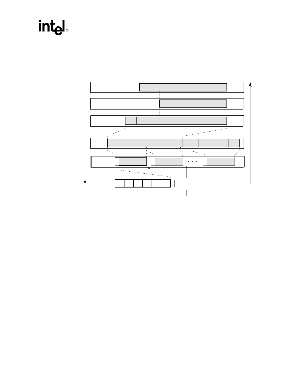
Figure 1 identifies how this design processes Ethernet, IP , an d AAL5 protocols., Reading from top
to bottom, Ethernet packets go through the LLC/SNAP Encapsulation, followed by segmentation
into ATM AAL5 cells. Reading from bottom to top, it also shows the reverse process, in which
AAL5 cells are reassembled into Ethernet packets.
8 Application Note
Modified on: 3/20/02,
Page 9
IXP1200 Network Processor Family ATM OC-3/12/Ethernet IP Router Example Design
Figure 1. IP over ATM Encapsulation Format
Ethernet
to ATM
Ethernet
Data
Enet Header IP Packet
IP
Data
(LLC/SNAP)
Encapsulation
AAL5
CS
SAR
Sub-layer
GFC
4 bits
LLC
3 bytes
CS-SDU Info Field
Payload
48 bytes
VPI
VCI
8 bits
16 bits
OUT
3 bytes
PTI
3 bits
IP Header Payload
PID
2 bytes
Payload
48 bytes
CLP
HEC
1 bit
8 bits
IP Packet
Padding
0-47 bytesUU1 byte
ATM Header
(5 bytes)
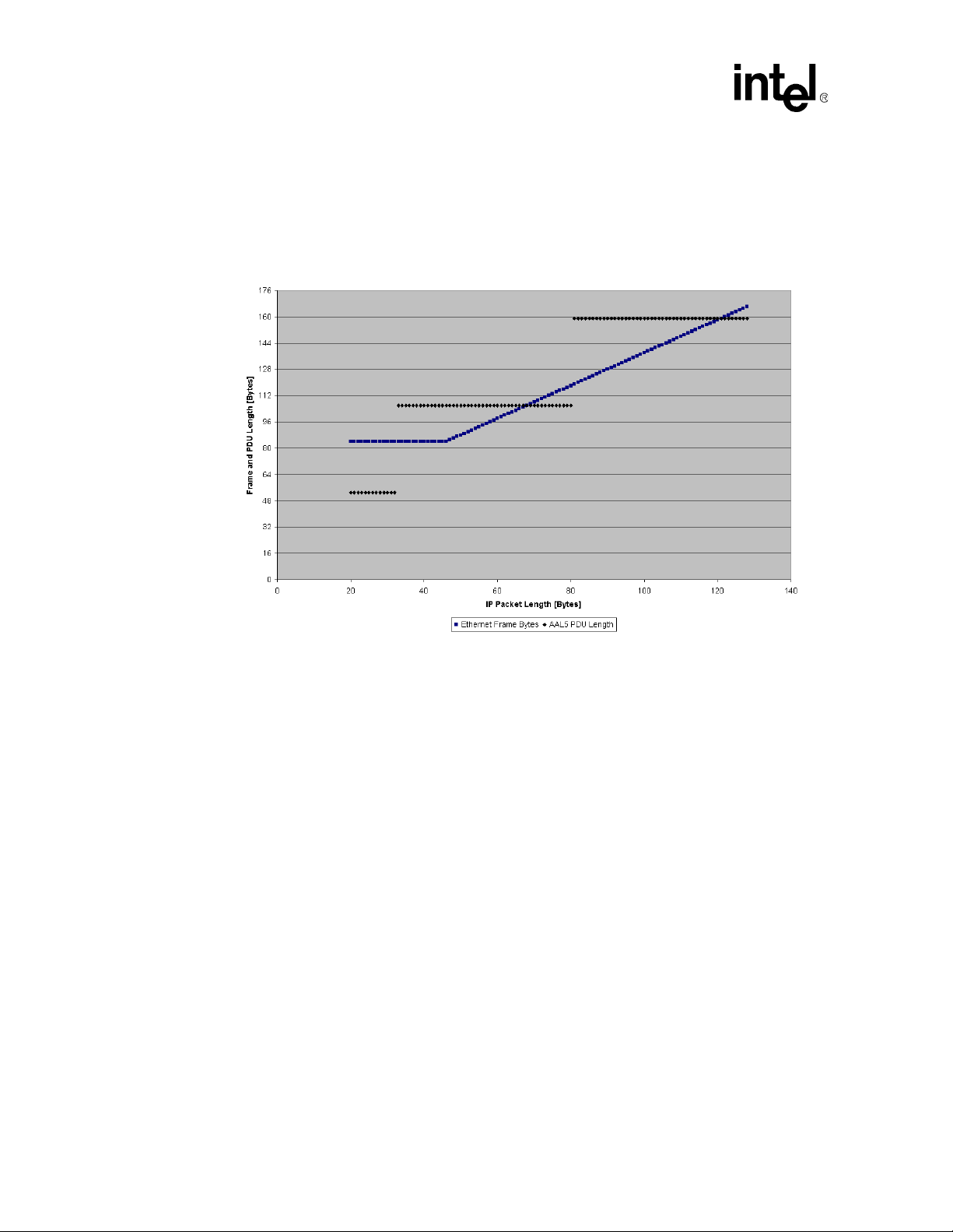
1.3.2 Frame and PDU Length vs. IP Packet Length
Figure 2 shows the relationship between IP Packet Length (X axis), Ethernet Frame Length, and
AAL5 PDU length (Y axis). Packet lengths 20 - 128 bytes are shown to illustrate 1-, 2-, and 3-cell
PDUs. The same pattern continues through the maximum Ethernet MTU size - the 1500 byte
packet, which requires 32 cells. There are a few important items to notice on this graph:
Length
CPI
2 bytes
1 byte
48 bytes
ATM Cell
Cells from other VCs
can be interleaved with
cells from this VC
4 bytes
Payload
CRC
ATM to
Ethernet
A8921-01
• 1.The smallest possible Ethernet frame is 64-bytes, which includes the IP packet in addition to
a 14-byte Ethernet header and 4-byte FCS. Adding an 8-byte preamble and 12-byte interframe
gap (960ns) to this frame increases it’s wire-occupancy time to 84 bytes. After IP packet length
exceeds 46 bytes, Ethernet frame length is a linear function of IP packet length.
• AAL5 PDU length is a step-wise function of IP packet length, due to rounding up to ATM cell
boundaries. At 53 bytes per cell, the 4-byte ATM header and 1 byte HEC are included here, but
the physical layer SONET overhead is not shown.
• The smallest possible IP packet, 20 bytes, corresponds to an IP header that does not contain an
IP payload. This packet fits into a single cell PDU, as do packets up to size 32 bytes (20 byte
IP header plus 12 paylo ad bytes).
• Minimized TCP/IP packets are 40 bytes - 20 byte IP header, 20 byte TCP header, and 0 TCP
payload bytes. These "40 byte packets" require 2 cell PDUs - they do not fit into single cell
Application Note 9
Modified on: 3/20/02,
Page 10
IXP1200 Network Processor Family ATM OC-3/12/Ethernet IP Router Example Design
PDUs because 8-bytes of LLC/SNAP plus 8 bytes of AAL5 trailer pu sh them over the 48 byte
payload capacity of a single ATM cell.
• Fully populated 64-byte minimum-sized Ethernet frames carry 46-byte IP packets, and also fit
into 2 cell PDUs, as do IP packets up through 80 bytes.
Figure 2. Frame and PDU Length vs. IP Packet Length
1.3.3 Expected Ethernet Transmit Bandwidth
This example design has more Ethernet transmit wire capacity than most full-bandwidth ATM
input workloads is able to consume. All configurations of this example design include more
Ethernet bandwidth than ATM bandwidth. This assures that Ethernet reception is fast enough to
supply ATM transmit at full wire rate, and that Ethernet can transmit fast enough to consume A TM
receive at full wire rate.
When Ethernet receive bandwidth exceeds ATM transmit wire-rate, the design discards the excess
Ethernet input. In the reverse direction, ATM receive wire-rate is less than Ethernet transmit wirerate, and so Ethernet transmit will never be fully consumed.
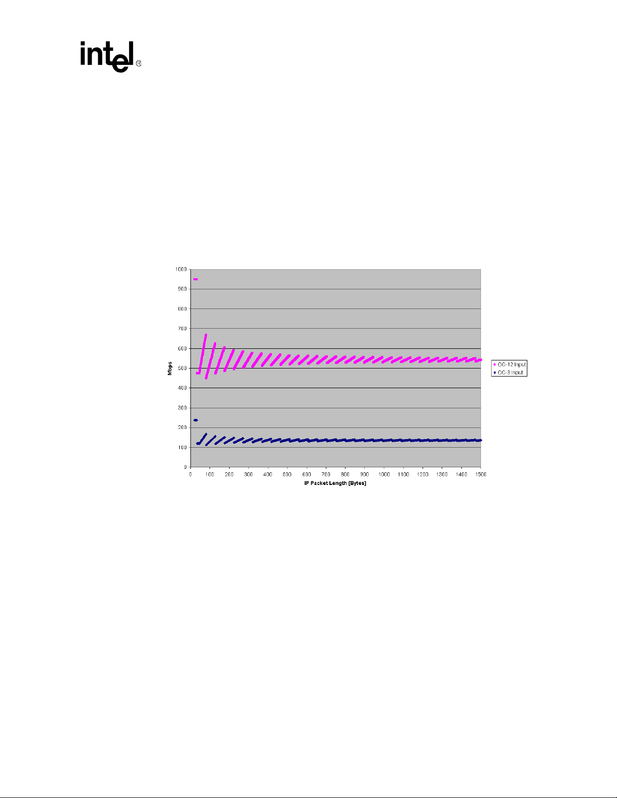
Given that the design receives cells at OC-3 or OC-12 wire-rate, Figure 3 shows the expected
Ethernet Transmit bandwidth. This pattern is a direct result of the minimum Ethernet frame size
and cell granularity of AAL5 shown in the previous figure. For exampl e, a 32-byte IP packet would
completely fill one cell, and when forwarded to Ethernet, Ethernet it expands to consume the entire
84-bytes of wire-time associated with a 64-byte minimum size Ethernet frame. In this scenario
ATM is more Mbps efficient than Ethernet, 949 Mbps Ethernet output would be expected.
However, as only 800Mbps of Ethernet bandwidth is available, the one-cell PDU workload will
drive the Ethernet wires to their 800Mbps capacity and discard the last 149Mbps.
10 Application Note
Modified on: 3/20/02,
Page 11
IXP1200 Network Processor Family ATM OC-3/12/Ethernet IP Router Example Design
A 33-byte IP packet overflows into 2 cells, requiring 53 more bytes on the input wire. This
effectively slows down the input rate, and the theoretical best-case Ethernet Transmit bandwidth
for this input drops to 475Mbps, well within the capacity of the 8 100Mbps Ethernet ports. Indeed,
only in the one-cell/PDU case does the Ethernet transmit bandwidth requirement exceed the
800Mbps available.
As packets grow larger , the n et ef fect of over flowing to the next cell is smaller. However, the peaks
in maximum bandwidth are also lower, reflecting the additional ATM header that is needed for
each additional cell in the PDU.
The following figure identifies the expected aggr egate Ethernet tran smit bandwid th for ATM OC-3
and OC-12 wire-rate input:
Figure 3. Expected Ethernet Transmit Bandwidth
1.4 Execution Environment
1.4.1 Software
The software execution environment supported by the Developer’s Workbench is described in the
README.txt file that accompanies the source code files for the project. This includes descriptions
of the directory and file structure, and project reconfiguration instructions. See Section 5.0 for
additional information on configuring the project.
The software simulation of the example design consumes test data streams from the Data Stream
feature of the Developer’s Workbench or through a network simulator Dynamic Linked Library
(DLL). Sample Ethernet and ATM data streams are provided.
Application Note 11
Modified on: 3/20/02,
Page 12
IXP1200 Network Processor Family ATM OC-3/12/Ethernet IP Router Example Design
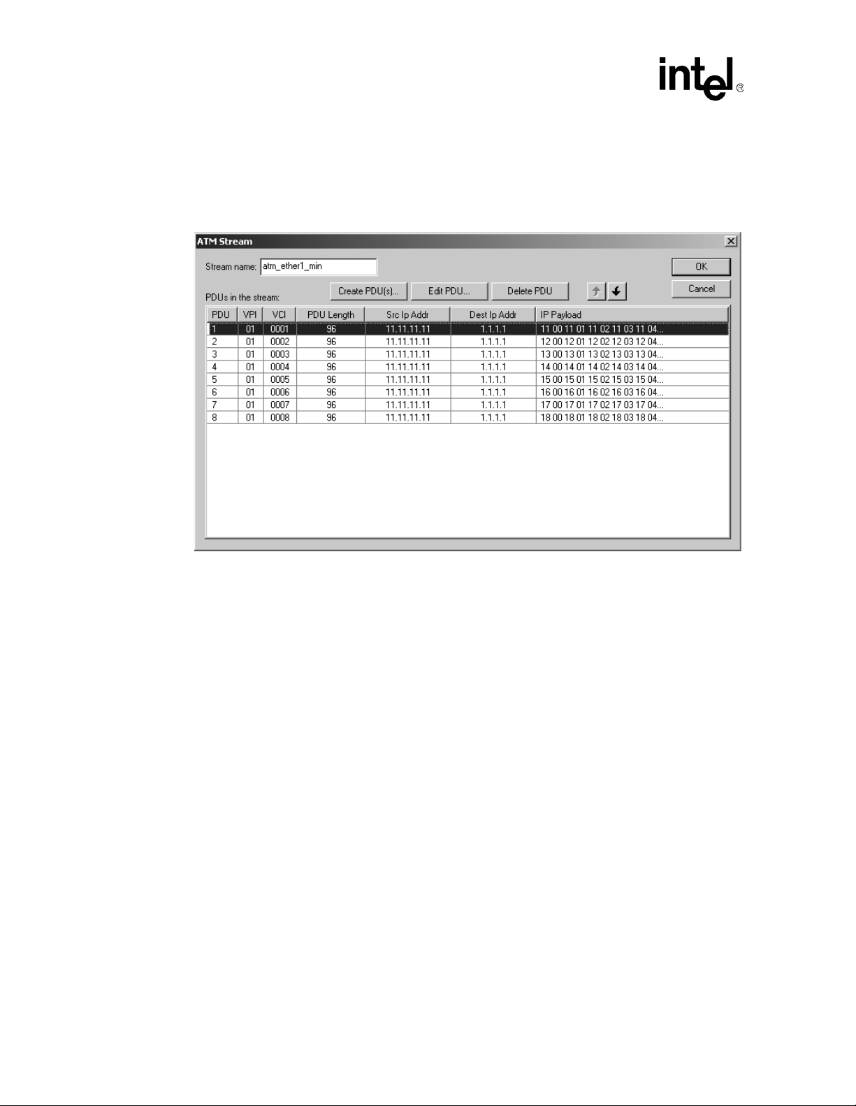
Figure 4 shows how data stream PDUs can be created in the Workbench for ATM, Ethernet, IP, and
other protocol data streams. These data streams can then be assigned to feed different ports. To test
how the example design performs IP routing, different destination IP addresses can be chosen in
the PDU.
Figure 4. Developer’s Workbench - ATM Data Stream Dialog Box
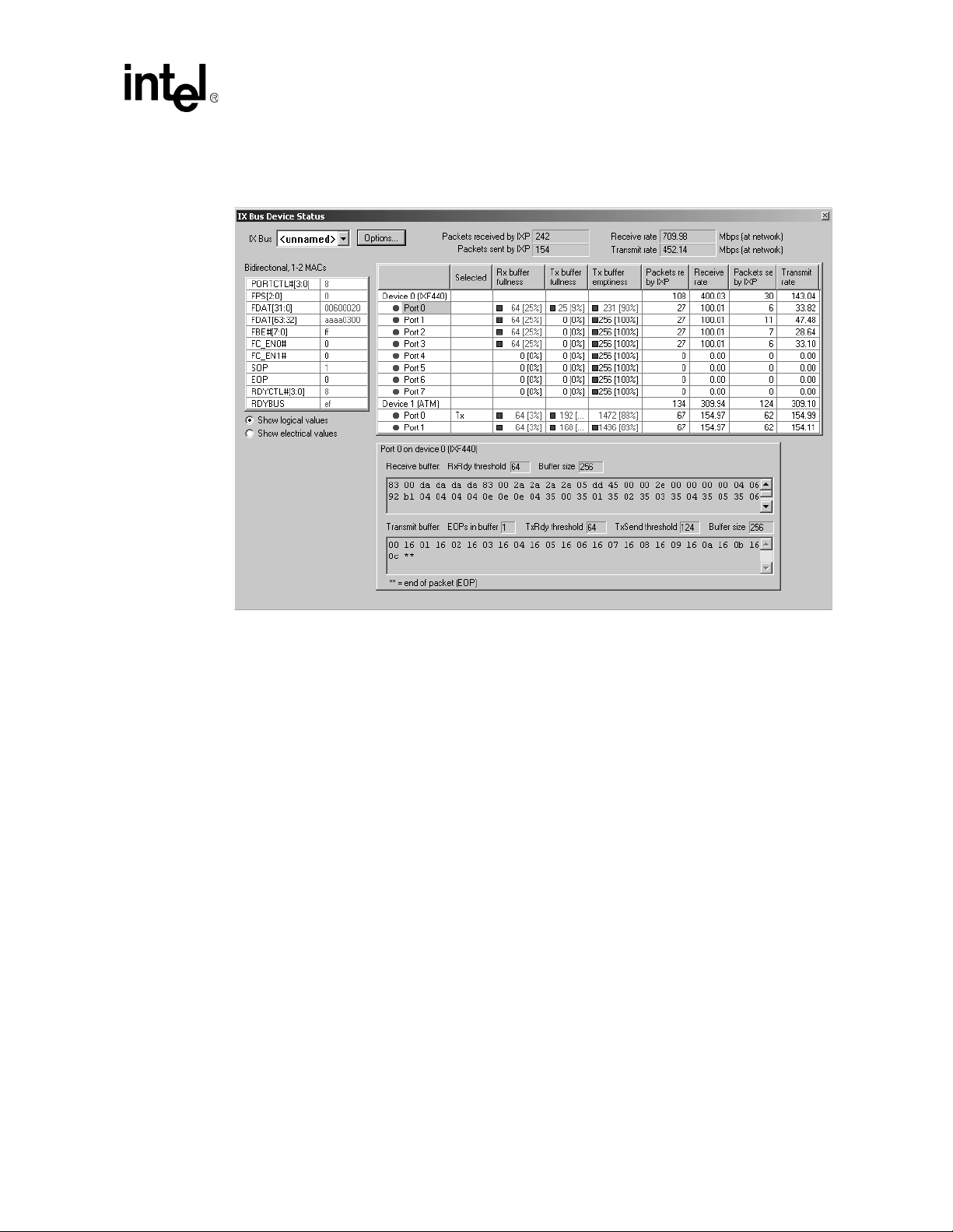
Figure 5 shows the IX Bus Device Status window. This window gives a continually updated
snapshot of IX Bus activity. It can be used to gain an overall picture of what data is being
transferred over the IX Bus "on-the-fly", and the data or wire transmission rate. The Data
Streaming feature and the IX Bus Device Status window are both documented in the IXP1200
Development Tools User’s Guide.
In the simulation environment, the IP and ATM VC table management software that normally run
on the StrongARM core are emulated with a combination of Transactor (simulator) foreign mode ls
and interpreted Transactor scripts.
12 Application Note
Modified on: 3/20/02,
Page 13
IXP1200 Network Processor Family ATM OC-3/12/Ethernet IP Router Example Design
.
Figure 5. Developer’s Workbench - IX Bus Device Status Window
1.4.2 Hardware
The README.txt file contained in the vxworks subdirectory of the project source code describes
how to build and run the project on h ardware using VxWorks
simulation mode by default, some simple changes to the project configuration must be made before
it will run on hardware. To run on hardware, Tornado 2.1
Workbench 2.01 need to be installed on the host system. Further details may be found in the
README.txt file in the vxworks subdirectory.
2.0 System Overview
2.1 System Programming Model
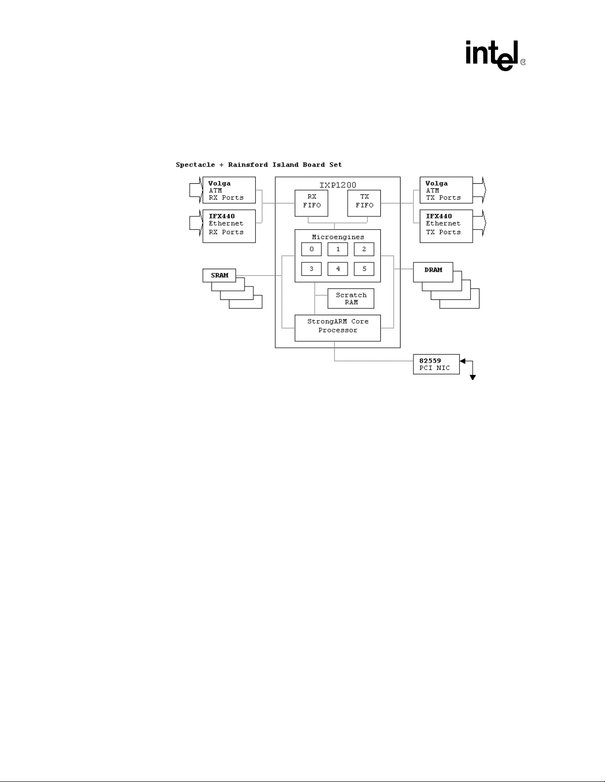
Figure 6 shows the system hardware, as seen by the software. Data flows from the receive p orts on
the left, through the IXP12xx’s RFIFO and its various hardware resources, and then to the TFIFO
and out the transmit ports on the right. ( While logically indepe nden t, receive and tran sm it po rts for
each interface are implemented in the same physical hardware package. The figure uses a single
block arrow to illustrate 1-4 AT M por ts, and 1 -8 Ethernet por ts, d epending on the configuration.)
®
. While the project runs in
®
as well as the IXP1200 Developer’s
Application Note 13
Modified on: 3/20/02,
Page 14
IXP1200 Network Processor Family ATM OC-3/12/Ethernet IP Router Example Design
The StrongARM core shares access to SRAM and DRAM with the microengines, and thus can
manage the VC and IP tables. The StrongARM core runs a Developer’s Workbench debug library
to connect to Developer’s Workbench running on a remote ho st t o debu g an d download microcode.
Figure 6. System Programming Model
2.2 StrongARM Core Software
In this example implementation, the StrongARM core runs VxWorks, and initializes the hardware;
controls the baseboard 82559 PCI Ethernet NIC; runs the IXP1200 Developer's Workbench debug
library, and connects it to a remote system host via the PCI Ethernet NIC; runs various startup
utilities (including atm_init() to initialize the IP route and VC Lookup tables) and provides those
utilities for run-time; and runs an agent to consume exception packets which are not handled by the
microengines in the data plane.
In the simulation environment, the IP and VC table management software are emulated with
Transactor foreign models - DLLs which are linked into the Transactor. The same source code is
compiled into the Transactor foreign models for SIMULATION, and th e VxWorks utilities to run
on HARDWARE.
14 Application Note
Modified on: 3/20/02,
Page 15
IXP1200 Network Processor Family ATM OC-3/12/Ethernet IP Router Example Design
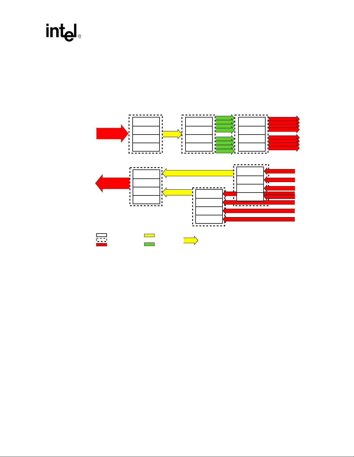
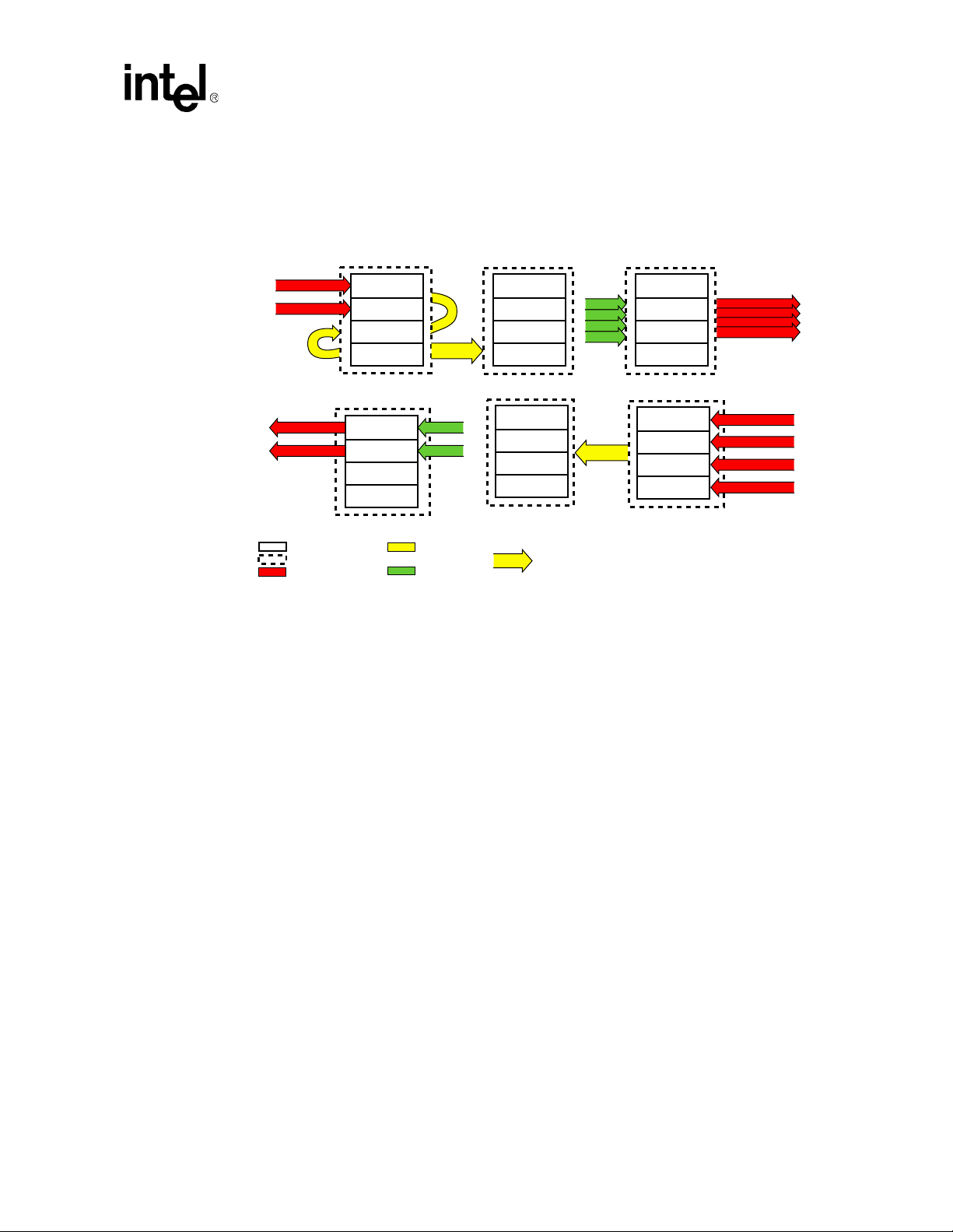
2.3 Software Partitioning
The following figures show how the microcode functional blocks are partitioned on IXP12xx
hardware for the three system configurations.
Figure 7. IXP1240 1xATM OC-12 and 8xEthernet 100Mbps Microengine Partitioning
Ethernet TX
Ethernet RX
Ethernet
Ethernet
Ethernet
Ethernet
Scheduler
Fill
Fill
Fill
Port0
Port1
Port2
Port3
Ethernet
Ethernet
Ethernet
Ethernet
Ethernet
Ethernet
Ethernet
Ethernet
Ethernet
Ethernet
Ethernet
Ethernet
A9634-01
OC-12 Port
OC-12 Port
Legend:
= Thread
= Microengine
= Physical Port
ATM RX
Port 8
Port 8
Port 8
Port 8
ATM TX
Fill
Fill
Fill
Unused
MSGQ
MSGQ
= Scratchpad
Memory
= SRAM
IPR
IP Route
IP Route
IP Route
IP Route
MSGQ
Ethernet RX
Port4
Port5
Port6
Port7
= MSGQ
PktQ
PktQ
PktQ
PktQ
PktQ
PktQ
PktQ
PktQ
All three figures show the ATM ports on the left, and the Ethernet ports on the right. All ports are
bi-directional, but are shown as uni-directional for clarity. The IX bus is configured in dual 32 bit
unidirectional mode.
The ATM Receive microengine uses the SRAM VC Lookup Table to assemble ATM cells into
AAL5 PDUs in DRAM. It forwards the descriptor to the fully-assembled PDUs to the IP Route
microengine via a single message queue (MSGQ) in scratchpad RAM.
The IP Route microengine reads the IP header from DRAM, performs additional checks per
RFC1812, performs an IP lookup to make a routing decision, then enqueues the Ethernet frame to
the appropriate Ethernet Transmit packet queue. In the Software CRC configuration, the packet is
processed by a CRC-32 checking microengine before being enqueued to an Ethernet transmit
packet.
In the reverse direction, Ethernet frames are received on the Ethernet ports by the Ethernet receive
microengine(s), which perform IP lookup and RFC1812 check s. The packets are then enqueued on
the appropriate queues to be consumed by the ATM transmit microengine. In the software CRC
configuration Figure 9, the PDUs are first processed by a CRC generation microengine before
going to the ATM Transmit microengine.
Application Note 15
Modified on: 3/20/02,
Page 16
IXP1200 Network Processor Family ATM OC-3/12/Ethernet IP Router Example Design
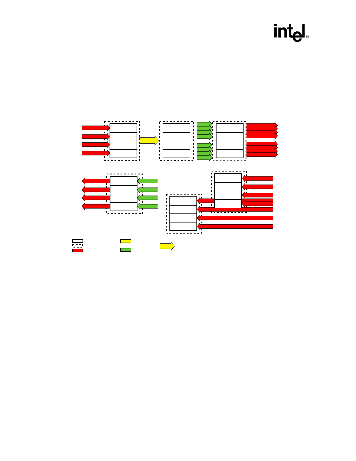
In the OC-12 configuration, there are two message queues (MSGQs) in scratchpad RAM, one for
PDUs from each Ethernet Receive microengine. The pool of threads in the ATM transmit
microengine alternately poll the two MSGQs.
In the OC-3 configurations, there is a buffer descriptor queue (BDQ) in SRAM associated with
each ATM transmit port. BDQs are similar to packetqs, but they are slightly more efficient in
configurations, where for example the transmitter dedicates a thread to each BDQ.
Figure 8. IXP1240 OC-3 4xATM and 8xEthernet 100Mbps Microengine Partitioning
Ethernet TX
Scheduler
Fill
Fill
Fill
Ethernet
Ethernet
Ethernet
Ethernet
Ethernet
Ethernet
Ethernet
Ethernet
OC-3
OC-3
OC-3
OC-3
ATM RX
Port 8
Port 9
Port 10
Port 11
MSGQ
IPR
IP Route
IP Route
IP Route
IP Route
PktQ
PktQ
PktQ
PktQ
PktQ
PktQ
PktQ
PktQ
ATM TX
OC-3
OC-3
OC-3
OC-3
Legend:
= Thread
= Microengine
= Physical Port
Port 8
Port 9
Port 10
Port 11
2.3.1 Lookup Tables
Not shown in the diagrams, the microengines make use of either three or four lookup tables:
• VC Lookup Table - resides in SRAM and is used by the ATM Receive microengine.
• IP Lookup Table - resides partially in SRAM and partially in DRAM, and is used by the IP
Route microengine and the Ethernet Receive microengine.
• MAC Address Hash Table - resides in SRAM and is used for RFC 1812 Port address
verification.
• Software CRC configurations use a table of pre-computed CRC-32 syndromes in SRAM.
BDQ
BDQ
BDQ
BDQ
= Scratchpad
Memory
= SRAM
Ethernet RX
Port4
Port5
Port6
Port7
= MSGQ
Ethernet RX
Ethernet
Ethernet
Ethernet
Ethernet
Port0
Port1
Port2
Port3
Ethernet
Ethernet
Ethernet
Ethernet
16 Application Note
Modified on: 3/20/02,
Page 17
IXP1200 Network Processor Family ATM OC-3/12/Ethernet IP Router Example Design
Figure 9. IXP1200 2xATM OC-3 Software-CRC and 4xEthernet 100Mbps Microengine
Partitioning
ATM RX
OC-3
OC-3
OC-3
OC-3
Legend:
= Thread
= Microengine
= Physical Port
Port 8
Port 9
IP Route
IP Route
ATM TX
Port 8
Port 9
Unused
Unused
MSGQ
BDQ
BDQ
= Scratchpad
Memory
= SRAM
2.4 Data Flow
2.4.1 ATM to Ethernet Data Flow
*
CRC CHK
Check
Check
Check
Check
CRC GEN
Generate
Generate
Generate
Generate
= MSGQ
PktQ
PktQ
PktQ
PktQ
MSGQ
Ethernet TX
Scheduler
Fill
Fill
Fill
Ethernet RX
Port0
Port1
Port2
Port3
Ethernet
Ethernet
Ethernet
Ethernet
Ethernet
Ethernet
Ethernet
Ethernet
A9636-01
Figure 10 outlines th e processing to receive ATM cells and forward them to Ethernet ports. For a
given VC, three different types of cells of the PDU can arrive: the first cell, middle cells, and last
cell:
1. The first cell of the IP over ATM PDU contains three types of headers: ATM header, LLC/
SNAP header, and IP Header. This is sufficient information to make a forwarding decision.
The payload portion of this cell is moved directly from the RFIFO to DRAM.
2. Subsequent middle cells are moved directly from the RFIFO to DRAM without any additional
processing.
3. When the last cell of th e PDU (which contains the AAL5 trailer) is receiv ed, the payload of the
cell is moved directly from the RFIFO to DRAM, and the completed PDU is then enqueued
for Ethernet transmi s sion.
2.4.1.1 VC Lookup
A VC lookup is performed on each cell received over an ATM port. The appropriate VC Table
Entry is located using the VPI/VCI value in the ATM header plus the port number. The lookup
provides an DRAM packet buffer base address, plus the CRC-32 syndrome for the PDU. As each
additional payload is added to the DRAM buffer, the offset value is incremented and the CRC
Application Note 17
Modified on: 3/20/02,
Page 18
IXP1200 Network Processor Family ATM OC-3/12/Ethernet IP Router Example Design
syndrome is updated appropriately. The VC Table Entry also contains an AAL type field.
Currently, this example design supports only classical IP over ATM, where the AAL type can be
either 0 or 5. A value of 0 indicates that the VC is not open, so any cell received on that VC is
immediately discarded.
The LLC/SNAP field specifies the protocol type. Currently, the only valid value is 0x AA AA 03
00 00 00 08 00 (classical IP over ATM). While this implementation consumes and produces just
one valid LLC/SNAP pattern, this pattern is not hard-coded. The LLC/SNAP bits are included in
the IP route table entry, as well as the VC lookup table. This is to make it easy to modify the design,
not only support a different LLC/SNAP pattern, but also to be able to support different valid
patterns for each VC.
2.4.1.2 IP Lookup Ta ble
Each PDU contains an IP header in its first cell. Therefore, a single IP lookup is performed for each
PDU, regardless of the number of cells in the PDU.
Figure 10. ATM to Ethernet Processing Steps
ATM PDU on Rx Port
1
Receive
ATM Cell
LLC
ATM
Hdr
Hdr
IP
Payload
Hdr
VC Look-up check
LLC/SNAP header
on first cell
ATM
Hdr
If end of PDU
6
Check
length
8
Strip
AAL-5
trailer
IP
Lookup
Address
2
3
IP
VC Lookup Table Entry
VPI/VCI
CRC
LENCLPPAD UU
7
Check
CRC
IP look-up
on first cell
Route Table
Port
Port
number
type
AAL
LLC/SNAP
type
header
Move
payload
to buffer
header
Packet Buffer
5
Enet
Buffer
offset
SDRAM
Cell N
(40 Bytes)
Cell 1
(48 Bytes)
Cell 0
(48 Bytes)
Locate buffer & offset
4
Buffer base
address
Check CRC
on AAL-5 PDU
7
Ethernet PDU on Tx Port
Transmit
MPKT
Ether
Hdr
IP Payload
Build MPKT,
9
add Ethernet
header on first
MPKT
CRC-32
Residue
10
A9638-01
18 Application Note
Modified on: 3/20/02,
Page 19

IXP1200 Network Processor Family ATM OC-3/12/Ethernet IP Router Example Design
2.4.2 Ethern e t to ATM Data Flow
Figure 11 outlines the sequence of events that takes place when processing incoming Ethernet
packets. Incoming Ethernet packets can either fit within a single MPKT ("m-packet", 64 byte
packet "fragment"), or span multiple MPKTs. The SOP (start of packet) and EOP (end of packet)
bits indicate the starting and ending MPKTs. As MPKTs are rece ived, they are stored in an DRAM
data buffer.
When the first MPKT is received (SOP asserted), the IP header is read from the RFIFO, the header
checksum is checked, the appropriate IP fields are updated (i.e. TTL), and an IP lookup is
performed. The IP Lookup Table Entry tells the receiver which port to route to, and which LLC/
SNAP pattern to prepend to the PDU. The LLC/SNAP and modified IP headers are then written to
DRAM.
When the final MPKT is received (EOP asserted), the AAL5 trailer is written out to DRAM and the
fully assembled PDU is enqueued for ATM transmission.
Figure 11. Ethernet to ATM Processing Steps
Ethernet Frame on Rx Port
Receive
1
MPKT
Ether
HdrIPHdr
Set current port state on first
3
MPKT strip Enet header
Payload
Perform IP
2
lookup on SOP
IP Lookup
IP
Address
Port State
Buffer Base Address
SDRAM
Pack Buffer
Payload
MPKT N
5
Move
MPKT
payload to
buffer
Route Table
Port
Port
type
number
Buffer OffsetLength
ATM
header
4
Locate buffer & offset
Payload
MPKT 1
Payload
MPKT0
LLC
header
Generate CRC
on PDU
7
6
Add
LLC/SNAP
header &
AAL-5
trailer
on EOP
IP
LLC
Packet
Hdr
8
Place
on Tx
queue
ATM PDU on Tx Port
ATM
Hdr
AAL-5
trailer
Segmentation
Queues
UBR
Queue 0
UBR
Queue 1
Payload
9
Transmit
from
segmentation
queues on
transmit
add ATM
header
Port 0
Port 1
A9637-01
2.5 StrongARM Core Initia li zat ion
On hardware, NetApp_Init is linked into VxWorks, and does the following:
1. Initialize the hardware, including the MACs and PHYs via VxWorks network drivers.
2. Control the baseboard 82559 PCI Ethernet NIC.
Application Note 19
Modified on: 3/20/02,
Page 20

IXP1200 Network Processor Family ATM OC-3/12/Ethernet IP Router Example Design
3. Run the IXP1200 Developer’s Workbench debug library, and connects it to a remote system
host via the PCI Ethernet NIC to download and debug IXP1240 microcode.
Then, atm_init() is invoked to initialize data structures in memory:
• Buffer Descriptor Free-list.
• CRC-32 Lookup Table.
• IP Lookup T abl e.
• VC Lookup Table and hash miss free-list.
• IP directed broadcast address hash table.
• Ethernet receive port MAC address hash table.
On hardware, atm_init() resides in the atm_utils.o VxWorks-loadable module running on the
StrongARM core. In the simulation environment, atm_init() resides in the atm_util.dll foreign
model and is invoked from the Transactor startup script atm_ether_init.ind.
2.6 Microengine Initialization
One microengine includes system_init.uc and invokes system_init() at its beginning. system_init()
is the central microcode initialization macro. It handles initialization not handled by th e
StrongARM core, and then sends a signal to thread0 of every microengine, including itself.
(system_init() can be invoked from any microengine. ether_tx_threads.uc is used simply because
of available microstore space.)
Reset causes every microengine to execute thread0 first, so every microengine begins with thread0
waiting for the inter-thread signal from system_init(). Upon receipt, thread0 i s responsible for
starting up the microengine in an orderly fashion, e.g. initializing absolute registers and sig n a ling
the other threads to start.
3.0 Microengine Functional Blocks
3.1 ATM Receive Microengine
The ATM Receive microengine is a single microengine dedicated to receive cells from the ATM
ports, check CRC-32 while re-assembling them into PDUs, an d then for ward them to the I P Router
microengine. (In the software CRC configuration, an additional microengine is used to handle
CRC checking.)
3.1.1 Structure
The following identifies the ATM Receive microengine structure for OC-12 and OC-3 ports:
OC-12 Port OC-3 Ports
Four threads working in parallel on one port. One thread/port.
20 Application Note
Modified on: 3/20/02,
Page 21

IXP1200 Network Processor Family ATM OC-3/12/Ethernet IP Router Example Design
OC-12 Port OC-3 Ports
"Fast-port" speculative receive requests. "Slow-port" status check before receive requests.
VC Cache enabled. VC Cache disabled.
NUMBER_OF_ATM_PORTS must be 1. NUMBER_OF_ATM_PORTS may be 1, 2, or 4.
3.1.2 High Level Algorithm
In all configurations, each Receive thread gets its own RFIFO element, as assigned by
port_rx_init().
Figure 12. ATM Receive High Level Algorithm
while(1)
#if (ATM_OC3_PORTS)
poll RCV_RDY_LO until port is ready
#endif
wait until < 3 receive requests in flight from this engine
receive cell from PHY to RFIFO
if (no Buffer Descriptor available "on deck")
pop buffer descriptor from free list.
read ATM header from RFIFO
#if (ATM_OC12_PORT)
if (RX_CANCEL)
handle & continue
#endif
if (RXFAIL)
handle & continue
if(not user cell)
handle & continue
#if (ATM_OC12_PORT)
if(ATM header hits in VC cache)
get VC info from VC cache
else // cache miss
allocate unused cache entry
#endif // ATM_OC12_PORT
look-up VC in hashed VC table
if (VC not open)
handle & continue
if (no Buffer Descriptor associated with VC)
assign "on deck" descriptor to this VC.
if (VC not open for AAL5)
drop cell & continue
if (first cell of PDU)
if (cell LLC/SNAP != VC table LLC/SNAP)
drop cell
move first cell to DRAM from RFIFO, calculate CRC-32
else
move nth cell to DRAM from RFIFO, calculate CRC-32
if (last cell of PDU)
if (bad CRC-32)
drop PDU, continue
if (AAL5 length == 0)
drop PDU, continue
update buffer descriptor
msgq_send() buffer descriptor to IP Route engine
else // not last cell
#if (ATM_OC12_PORT)
update and exit VC cache entry
#endif
update VC table entry
Application Note 21
Modified on: 3/20/02,
Page 22

IXP1200 Network Processor Family ATM OC-3/12/Ethernet IP Router Example Design
3.2 ATM Transmit Microengine
The ATM Transmit microengine is an AAL5 Unspecified Bit Rate (UBR) Transmitter that uses a
single microengine to move cells at wire-rate in either single OC-12 or up to four OC-3 port
configurations. No attempt is made to mix, schedule, or otherwise ’shape’ the order of the cells on
the wire.
The transmitter consumes PDUs one at a time from beginning to end, resulting in an output stream
in which cells from the same PDU are transmitted "back-to-back" from first through the last cell of
the PDU.
The transmitter is implemented with 3 identical fill threads. Unlike the Ethernet transmitter, the
ATM transmitter does not have a thread dedicated to scheduling the work of the fill threads. Rather,
the fill threads use shared absolute registers to act as a "distributed scheduler". The fourth thread
could also be enabled as a fill thread, but is not needed at the wire rates in this design.
In IXP1240/1250 hardware CRC configurati on s, th e ATM Transmitter generates CRC-32 upon
transferring cells from DRAM to the TFIFO. In the IXP1200 software CRC configurations, CRC32 is computed by a dedicated CRC-32 generation microengine.
3.2.1 High Level Algorithm
Figure 13. ATM Transmit High Level Algorithm
while(1)
critsect_enter(@poll_for_new_work_mutex)
if (engine not active sending a PDU)
dequeue a PDU
if (Rosetta not ready to transmit)
goto skip#
critsect_exit(@poll_for_new_work_mutex)
get transmit (cell) assignment from active PDU
sequence_enter(SEQ_TFIFO) - remember TIFO element allocation order
_atm_tfifo_element() to claim the next TIFO element
write payload from DRAM to TFIFO
_build_atm_tx_assignment() set-up TFIFO control word
_my_tfifo_status_write() write control to TFIFO
atm_tx_tfifo_write_cell_header_and_data0() – ATM header into TFIFO
sequence_wait(SEQ_TFIFO) - wait for my element to be next
tfifo_ptr_wait() - don't validate too far ahead of xmit_ptr
tfifo_validate_write()
sequence_exit(SEQ_TFIFO)
continue
skip#: // skip a TIFO element
critsect_exit(@poll_for_new_work_mutex)
sequence_enter(SEQ_TFIFO) - remember TIFO element allocation order
_atm_tfifo_element() - to claim the next TIFO element
_my_tfifo_skipstatus_write() - write control to TFIFO
sequence_wait(SEQ_TFIFO) - wait for my element to be next
tfifo_ptr_wait() - don't validate too far ahead of xmit_ptr
tfifo_validate_write()
sequence_exit(SEQ_TFIFO)
22 Application Note
Modified on: 3/20/02,
Page 23

IXP1200 Network Processor Family ATM OC-3/12/Ethernet IP Router Example Design
3.3 IP-Router Microengine
The IP Router microengine consumes packets from the ATM receive microengine via a message
queue, and routes them to the approp riate Ethernet transmit packetq. In the IXP1200 software-CRC
configuration, this function is carried out by two threads residin g on the ATM Receive microengine
rather than on a dedicated IP router microengine.
3.3.1 Structure
All threads are identical. In hardware-CRC configurations, four IP Router threads reside on the
dedicated IP-router microengine. In the software-CRC configuration, two IP Router threads reside
on the ATM Receive microengine.
3.3.2 High Level Algorithm
Figure 14. IP Router High Level Algorithm
while(1)
msgq_receive() packet from ATM RX engine
ip_filter() out SNMP, IGMP
ip_addr_validation() to discard packets from reserved addresses
ip_dbcast_check() to filter out packets from directed broadcast addresses
ip_proc()
ip_verify() check TTL and checksum
ip_modify() update TTL
ip_route_lookup()
port_enabled_check() to discard packets from disabled port
update Ethernet MAC Source Address with our own
#ifdef ATM_LOOPBACK //Allow hardware configurations with ATM outputs
if(output port == ATM port)
over-ride ATM destination port with round-robin Ethernet port
#endif
packetq_send() packet to destination Ethernet port
//connected directly to ATM inputs
3.4 Ethernet Receive Microengine
The Ethernet Receive microengine is based on rx_ether100m.uc, an extended version of the
Ethernet receive threads from the Software Development Kit’s (SDK's) 16-port Ethernet example
1
. While the code looks quite different from that on the SDK, most of the changes required a
design
simple move to a more efficient structure, without changing the logical function of the
microengine. For example, the threads take advantage of updated APIs for the RFC1812 macros to
lower the overhead of RFC1812 support.
Semantically, there are only a few differences from the SDK Ethernet design.
• IP lookup can return an ATM destination port, or an Ethernet destination port.
• For ATM destinations, prepend the LLC/SNAP to the payload.
• For ATM destinations, append the AAL5 trailer.
1. The SDK (Software Develo pm ent Kit) 2.01 CD contains a number of earlier IXP1200 Ethern et exa m pl e designs that have remained
relatively unchanged from previous releases of the SDK. The Ethernet receive and transmit code in this example design reuses that code with
few modifications
Application Note 23
Modified on: 3/20/02,
Page 24

IXP1200 Network Processor Family ATM OC-3/12/Ethernet IP Router Example Design
• For A TM destinations, enqueue to the ATM Transmit microengine, or for software CRC, to the
appropriate AAL5 CRC-32 generation queues.
The ETHERNET_LOOPBACK build option enables routing packets from Ethernet Receive ports
to Ethernet Transmit ports. This is useful for equipment checkout in the lab. If this option is not
defined, packets received from ethernet ports which route to ethernet output ports are discarded
with IP_NO_ROUTE exception. If this option is defined, the packets are forwarded as requested.
3.4.1 Ethernet Receive Structure
There are four identical threads on each Ethernet receive microengine. Each thread services a
specific port and uses a specific RFIFO element.
3.4.2 Ethernet Receive High Level Algorithm
Figure 15. Ethernet Receive High Level Algorithm
while(1)
if(no receive buffer in hand)
allocate a receive buffer
receive MPKT from MAC to RFIFO
if(SOP)
read link layer header from RFIFO
if (not Ethernet)
record output queue to be to StrongARM core
else
transfer end of MPKT from RFIFO to DRAM
read IP header from RFIFO
if (IP header checksum error)
remember to discard this packet
endif
update IP header TTL and checksum
ip_lookup()
write LLC/SNAP and modified IP header to DRAM
endif
else // !SOP
extract byte count from receive state
transfer MPKT from RFIFO to DRAM data buffer
endif
if(EOP)
write AAL5 trailer
enqueue PDU to ATM transmitter
endif
3.5 Ethernet Transmit Microengine
The Ethernet Transmit microengine is rooted in ether_tx_threads.uc, which simply includes
system_init.uc, invokes system_init(), sets some definitions, and inclu des tx_ether100m.uc from
the 16-port Ethernet example design on the 2.01 SDK.
Other than that change, there is only one other difference between this Ethernet transmitter and the
implementation used by SDK example designs like L3fwd8_1f. With RFC1812 enabled, the SDK
example designs place the Ports-With-Packets (PWP) vector in SRAM and polls it to find packets
to send. This design uses a more efficient implementation that polls an scratchpad resident PWP
vector for the data plane, and checks for a signal before polling an SRAM resident PWP vector to
consume packets from the StrongARM core.
24 Application Note
Modified on: 3/20/02,
Page 25

IXP1200 Network Processor Family ATM OC-3/12/Ethernet IP Router Example Design
3.5.1 Ethernet Transmit Structure
The Ethernet Transmit microengine contains three fill threads and one transmit scheduler thread.
The Ethernet transmitter uses the eight even TIFO elements, allowing the ATM transmitter to use
the eight odd Transmit FIFO elements. This is the same TFIFO sharing mechanism that is used by
the L3fwd8_1f SDK example, except here the peer transmitter is ATM instead of Ethernet.
3.5.2 High Level Algorithm
As mentioned in “project_config.h”, defining ETHERNET_LOOPBACK allows the project to
forward packets from Ethernet source po rts to Ethernet des tination ports. En abling this option adds
a small cost in the Ethernet transmitter because it needs to be able to handle transmit data starting
on variable buffer offsets.
This implementation uses thread0 as a scheduler, and the others are used as fill threads:
Thread0:
while(1)
tx_100m_assign()
tx_100m_assign() makes work assignments to the three fill threads of this microengine. Slow ports
are mapped directly to TFIFO elements. Therefore, if the target port has no packets, the fill thread
is given a ‘skip’ assignment. When the fill thread executes a skip assignment, it forces the
hardware to skip a TFIFO element without transmitting any data from the TFIFO element onto the
IX bus.
Threads1,2,3:
while(1)
read assignment from scheduler
restore portinfo state from absolute registers
if (assigned to transmit a packet)
transfer MPKT to TFIFO and validate
update portinfo state
else
skip TFIFO element
endif
3.6 CRC-32 Calculations using IXP1240/1250 Hardware
The IXP1240 adds sdram_crc[] instructions to the IXP1200 instruction set fo r efficient CRC
calculation. This design takes advantage of that hardware support in the ATM receiver and the
ATM transmitter. On receive (reassembly), CRC is checked when ATM cells are transferred from
RFIFO to DRAM. On transmit (segmentation), CRC is generated when ATM cells are transferred
from DRAM to the TFIFO.
3.6.1 CRC-32 Hardware Checking on Receive
Quadword 0 is copied with an sdram_crc[r_fifo_rd], mask_right instruction. This applies the CRC
to the four bytes labeled "LLC0" in Figure 16, but not to the ATM header. The ATM header is not
actually needed in the DRAM data buffer, but it is transferred, because this is more efficient than
performing a read/modify/write to preserve insignificant bits in the buffer.
Application Note 25
Modified on: 3/20/02,
Page 26

IXP1200 Network Processor Family ATM OC-3/12/Ethernet IP Router Example Design
Quadwords 1-5 are transferred by an sdram_crc[r_fifo_rd, 5] instruction. Quadword 6 contains
"Data 11" -- the eleventh 32-bit longword of the cell. Data 11 is stored in the VC table entry to be
consumed when the next cell in this PDU arrives. When the first cell is also the last cell (for
example, for a single-cell-PDU), Data11 contains the CRC-32 of the AAL5 trailer, and it is
compared to the one’s complement of the computed CRC syndrome.
Figure 16. First Cell of a PDU in RFIFO and in DRAM
01234567Bytes -> (Big Endian Diagram)
0 ATM Header LLC0
1 LLC1 IP
2IP
3IP
4 77778888
5 9 9 9 9 10101010
6 11111111 - - - -
This design can actually skip the first RFIFO->DRAM transfer because LLC0 is constant on the
first cell and it is explicitly compared with the LLC0 value in the microengine. After a successful
compare, it is stripped from the packet. With the following optimization enabling definition,, the
CRC computation begins with LLC1 using the syndrome that would result from CRC over LLC0
(with the initial configuration, it is enabled by default):
#define CRC32_RX_LLC0
The algorithm for transferring the nth cell of a PDU is slightly different than that for moving the
first cell - as illustrated in Figure 17.
Figure 17. Two-Cell PDU in DRAM
01234567Bytes -> (Big Endian Diagram)
0 ATM Header LLC
1 LLC IP
2IP
3IP
477778888
5999910101010
6 111111110 0 0 0
711112222
833334444
955556666
1077778888
119999AAL5*
12 CRC32* - - - -
Looking at the quadword on the row labeled 6:
• The four bytes labeled ’11’ make up the longword ’data11’ from the first cell. The four bytes
labeled ’0’ make up the longword ’data0’ from the second cell.
26 Application Note
Modified on: 3/20/02,
Page 27

IXP1200 Network Processor Family ATM OC-3/12/Ethernet IP Router Example Design
• Upon reception of the first cell, data11 is saved in the VC cache/table entry . Up on reception of
the 2nd cell, data11 is retrieved from the VC cache/table entry, combined with data0 of the
second cell, and written in a single burst to DRAM.
Moving the nth cell (not cell0) in a PDU from the RFIFO to DRAM is similar to using the macro
atm_move_cell0_rfifo_to_sdram(), except that:
• The nth cell must start with a run-time crc_residue resulting from CRC on the previous cell in
the PDU.
• The nth cell must combine data11 of the previous cell with data0, as shown in Figure 17.
3.6.2 CRC-32 Hardware Generation on Transmit
Figure 18 and Figure 19 show the layout of the cell source as it appears in DRAM, and the desired
format in the TIFO, respectively. Aspects of the first, nth, and last cell are all overlaid on the same
diagram, as the positions are the same. In each diagram, rows are 64-bit “quadwords”.
Figure 18. Transmit cell as seen in DRAM
0 1 2 3 4 5 6 7 Bytes -> (Big Endian Diagram)
0------LLC
1LLC IP
2IP
3IP
4IP
5 AAL5
6 AAL5 CRC32* CellN+1
Figure 19. Transmit cell seen in TFIFO
0 1 2 3 4 5 6 7 Bytes -> (Big Endian Diagram)
0 ATM Header LLC
1LLC1 IP
2IP
3IP
4
5AAL5
6 CRC32 - - - -
3.6.2.1 Transmit Alignment
The alignment of this cell in DRAM is dependent on how the data was received. In this example
design, the data was received on Ethernet, with a 14 byte Ethernet header. Therefore, the first byte
of the IP header starts on the 15th byte of the buffer.
The sdram_crc[t_fifo_wr] commands account for this alignment by using the IXP12xx byte
alignment hardware. These diagrams show bytes in big-endian order, while the instruction
encoding asks for byte alignment assuming little endian order. Therefore the 6-byte offset shown
here, becomes a 2-byte offset as encoded in the indirect_ref.
Application Note 27
Modified on: 3/20/02,
Page 28

IXP1200 Network Processor Family ATM OC-3/12/Ethernet IP Router Example Design
The hardware byte aligner operates on the data before the CRC computation hardware. This can be
seen in the transfer to quadword 0 of the TFIFO element with sdram_crc[t_fifo_wr], mask_right
with a byte alignment of 2 and a CRC mask value of 4.
Quadwords 1-5 are transferred with sdram_crc[t_fifo_wr, 5] with the same alignment. For
quadword 6, the processing depends upon whether or not it is the last cell of a PDU:
• If quadword 6 is not the last cell, it is transferred via sdram[t_fifo _wr], mask_left, then the
syndrome is extracted for use when the next cell is sent on this VC.
• If quadword 6 is the last cell, the syndrome is read after quadword 5 is finished, it is inverted
and transferred viat_fifo_wr[] to quadword 6 from the microengine.
In all cases, after the cell is transferred and CRC is done, the first quadword is overwritten by the
microengine to insert the ATM header on the front of the cell. As the TFIFO is addressable only as
quadwords, the write will also update the first four bytes of cell payload (labeled LLC0 in the
example diagram). To preserve these first four payload bytes, the microengine first reads them
from DRAM and combines them with the ATM header before overwriting quadword0.
As with LLC0 in the ATM receiver, this design can be optimized to take advantage of that the
constant LLC0 constitutes the first four bytes of payload on the first cell of a PDU (with the initial
configuration, it is enabled by default):
#define CRC32_TX_LLC0
3.7 CRC-32 Checker and Generator Microengines (Soft-CRC)
The CRC-32 microengine code, "Software CRC", is needed only for IXP1200 configurations.
IXP1240 or IXP1250 designs employ sdram_crc[] hardware instructions to perform the same
calculation more efficiently.
In IXP1200 configurations, there are two microengines dedicated to AAL5 CRC-32 calculations:
• One consumes the ATM Receive data stream and checks the CRC-32 before routing to
Ethernet Transmit packet-queues.
• One consumes the Ethernet Receive data stream and generates CRC-32 before forwarding to
the appropriate ATM Transmit queues.
3.7.1 Functional Differences between Checker and Generator
There are four functional differences between the Checker and Generator:
• DRAM data buffer payload alignment: depends on if it was received from ATM or Ethernet.
• Queues to be consumed.
• Queues to be supplied.
• CRC-32 answer - the checker compares it to the received CRC, while the Generator writes it
into the AAL5 trailer.
The source code is assembled into binaries optimal for Checking or Generating based on the
microengine number assignments from system_config.h.
#define CRC_CHECKER (UENGINE_ID == CRC32_CHECKER_UENGINE)
#define CRC_GENERATOR(UENGINE_ID == CRC32_GENERATOR_UENGINE)
28 Application Note
Modified on: 3/20/02,
Page 29

IXP1200 Network Processor Family ATM OC-3/12/Ethernet IP Router Example Design
3.7.2 CRC-32 Checker and Generator High Level Algorithm
Figure 20. CRC-32 High Level Algorithm
// CRC Checker
while(1)
dequeue PDU from CRC CHK BDQ
calculate_crc() over entire PDU
if (AAL5 trailer CRC == calculated CRC)
enqueue PDU onto Ethernet Transmit packet queue
else
drop PDU
endif
//CRC Generator
while(1)
dequeue PDU from CRC GEN BDQ
calculate_crc() over entire PDU
write calculated CRC into AAL5 trailer in DRAM data buffer
enqueue PDU onto ATM TX UBR BDQ
The PDUs within each VC on each port are enqueued on the output in the same order that they
were dequeued from the input.
3.7.3 CRC-32 Computation
CRC-32 computation is performed by the calculate_crc32() macro in atm_aal5_crc32lib.uc.
The data stream is used to index tables of pre-computed CRC-32 results. The results are combined
serially to produce the CRC-32 for the entire AAL5 PDU.
The lookup tables are generated by code in atm_aal5_crc32_table.c. In simulation, the code
produces files that contain the tables and are downloaded into SRAM by startup scripts.
For hardware, the tables are generated by the same code running on the StrongARM core, but
rather than creating files, the tables are written directly to memory.
4.0 Software Subsystems & Data Structures
4.1 Virtual Circuit Lookup Table - atm_vc_table.uc
4.1.1 VC Table Function
The ATM receive microengine uses a VC Lookup T ab le to manage r eassemb ly of cells into PDUs.
The virtual circuit address bits in each cell header, plus the receive port number , un iquely specify a
VC table entry for that VC. ATM Receive performs a VC Lookup to qualify every cell received.
The lookup returns the VC Lookup Table Entry structure with the format shown in Figure 23 and
Figure 24.
Application Note 29
Modified on: 3/20/02,
Page 30

IXP1200 Network Processor Family ATM OC-3/12/Ethernet IP Router Example Design
The OC-12 configuration uses a VC Table Cache in conjunction with the VC table, however the
description of the backing VC table in this section applies with or without the presence of a VC
Cache.
The VC table entry answers the following questions for the ATM Receive thread:
• Is the VC open? (If no, discard the cell)
• Which LLC/SNAP patterns are expected at the start of each PDU? (If no match, discard cell.)
• Which AAL is the VC open for? (ATM Receive currently processes only AAL5.)
• Where should ATM Receive put the payload in DRAM (buffer and offset)?
• For hardware CRC: what is the current syndrome for this PDU?
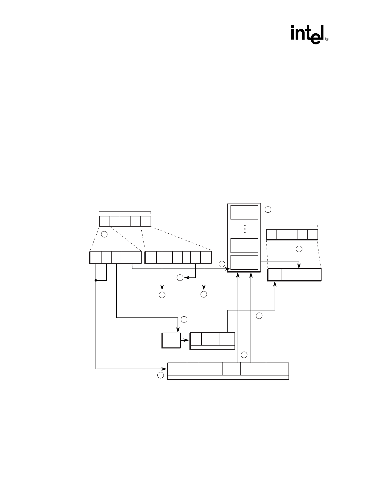
4.1.2 VC_TABLE_HASHED Structure
VC_TABLE_HASHED supports the entire ATM VC name-space by employing the IXP12xx
hashing hardware as follows:
• At initialization, microcode loads the hash48 multipli er CSRs with the largest prime number
that fits in to 48 bits: 0xffffffffff c5.
• At run-time, ATM Receive locates entries like so:
key = (atm_header & 0xFFFFFFF0) | port#)
hash_output = hash1_48[key]
Index = ((hash_output) ^ (hash_output >> 16) ^ (hash_output >> 32)) & 0xFFFF
The index is used to read an entry from a 64K entry "primary" hashed VC Table in SRAM. If the
key in the entry matches the starting key, the hash table has successfully delivered the right VC
table entry with just one SRAM read. If the key does not match the key in the entry read from the
primary table, it follows a linked "collision" list threaded with the entry "Next" field (see figure
Figure 23)
30 Application Note
Modified on: 3/20/02,
Page 31

IXP1200 Network Processor Family ATM OC-3/12/Ethernet IP Router Example Design
Figure 21. Hashed VC Table Structure
Primary VC Table
(SRAM)
Primary VC Entry
with a collision list
VC Entry on
collision list
Primary VC Entry
without a collision list
…
Hardware Top
of Stack Registers
Collision freelist starting with
SRAM top of stack register
When atm_vc_table_entry_create() attempts to add an entry to the table and determines that the
entry in the primary table is alread y o ccup ied, it needs to co me u p with an available entry to thread
onto the Next pointer. Although other implementations (which have less available RAM) take
entries from the primary table to perform this task, this implementation has a dedicated pool of 16K
collision entries that are available in a buf.uc style freelist threaded on hardware stack 1. The
motivation is that VC lookup is on the critical performance path. Therefore, this design needs to
maximize the chances that entries will be found in the primary table rather than on the collision
lists. However, the optimal primary table and collision free-list sizes will depend on the target
workload (an implementation issue).
4.1.3 VC_TABLE_LINEAR Structure
VC_TABLE_LINEAR implements a simple linear array of VC table entry structures in SRAM.
The size of the table depends on the number of VCs being supported, which correspondingly
depends on the number of ports and the number of significant VCI and VPI bits in the ATM header .
The defaults for these parameters are set in system_config.h, and can be overridden in
project_config.h.
VC Entry at
end of freelist
. . .
A9633-01
Application Note 31
Modified on: 3/20/02,
Page 32

IXP1200 Network Processor Family ATM OC-3/12/Ethernet IP Router Example Design
Figure 22. VC Ta ble Index
bit positions: Z Y X
- Port VPI VCI
Bit Position Description
X VCI_SIGNIFICANT_BITS - 1
Y VCI_SIGNIFICANT_BITS + VPI_SIGNIFICANT_BITS - 1
Z VCI_SIGNIFICANT_BITS + VPI_SIGNIFICANT_BITS + PORT_SIGNIFICANT_BITS - 1
The project defaults to support a 64K-entry VC table - independent of the number of ports. It does
this with eight significant VCI bits, and eight more bits split between VPI and ports. This means
that the design can distinguish the difference between 64K different VCs. However, it does not
mean that the design can simultaneously reassemble PDUs on all 6 4K entries. The sys tem supports
only 16K packet buffers, and would run out of buffers were it to attempt to assemble PDUs on
more than 16K VCs.
4.1.4 VC Table Management API - atm_utils.c
atm_utils.c implements C-language utilities to manage the VC Lookup Table. These utilities are
available both in simulation at the Transactor command prompt, as well as VxWorks kernel entry
points.
The current implementation assumes Permanent Virtual Circuits (PVCs), i.e. it does not support the
StrongARM core updating the VC table while the microcode is using the table. Switched Virtual
Circuit (SVC) support could be added by employing SRAM locks or atomic operations to avoid
conflicts between simultaneous StrongARM core and microengine access to the same VC entry.
4.1.5 VC Table Entry
The format of the VC Table entry for VC_TABLE_HASHED is the same as for
VC_TABLE_LINEAR, with the addition of 2 32-bit words to hold the Next address and the hash
Key for the entry.
This format is only partially hidden from ATM Receive, the consumer of the VC table API, though
macros could be implemented to make it appear to opaque.
Figure 23. VC Lookup Entry Table (VC_TABLE_HASHED)
3130292827262524232221201918171615141312111
00 Next
1Key
2 Buffer Offset Buffer Index LLC/SNAP Q AAL
3 CRC
4 Cell data11
9876543210
0
32 Application Note
Modified on: 3/20/02,
Page 33

IXP1200 Network Processor Family ATM OC-3/12/Ethernet IP Router Example Design
Entry Description
Next
Key
Buffer Offset
Buffer Index
LLC/SNAP
Q
AAL
CRC
Cell Data11
Address of the next entry in the chain of entries that hash to the same row. 0 indicates no
next entry. (21 bit SRAM address)
Hash key used to find this entry, also used to confirm arrival at the desired entry. Key =
(atm_header & 0xFFFFFFF0) | port#
Indicates which 64-bit DRAM word in the buffer should receive the next payload. On
completion of PDU assembly, this field is copied to the buffer descriptor.
Buffer descriptor (and data buffer) to be used by ATM Receive to deposit payloads on this
VC.
1: LLC0_IP, LLC1_IP
else: available for other patterns
Queue To St rongARM core "Q" flag
1: queue all traffic to core
0: do not queue to core
5: ATM Adaptation Layer 5
0: VC is not open
The CRC-32 syndrome associated with the PDU. It is saved in the VC table entry after a cell
is moved, and then retrieved and used when the next cell in the PDU is received.
The last four bytes of the previous cell in this PDU. Used during re-assembly of PDUs to
allow 8-byte quadword burst writes to DRAM without using DRAM Read/Modify/Write
instructions.
Figure 24. VC Lookup Table Entry (VC_TABLE_LINEAR)
3130292827262524232221201918171615141312111
0 Buffer Offset Buffer Index LLC/SNAP Q A AL
1CRC
2 Cell data11
Entry Description
Buffer Offset
Buffer Index Buffer descriptor (and data buffer) to be used by ATM Receive to deposit payloads on this VC.
LLC/SNAP
Q
Indicates which 64-bit DRAM word in the buffer should receive the next payload. On
completion of PDU assembly, this field is copied to the buffer descriptor.
1: LLC0_IP, LLC1_IP
else: available for other patterns
Queue To St rongARM core "Q" flag
1: queue all traffic to core
0: do not queue to core
9876543210
0
Application Note 33
Modified on: 3/20/02,
Page 34

IXP1200 Network Processor Family ATM OC-3/12/Ethernet IP Router Example Design
Entry Description
AAL
CRC
Cell Data11
5: ATM Adaptation Layer 5
0: VC is not open
The CRC-32 syndrome associated with the PDU. It is saved in the VC table entry after a cell
is moved, and then retrieved and used when the next cell in the PDU is received.
The last four bytes of the previous cell in this PDU. Used during re-assembly of PDUs to allow
8-byte quadword burst writes to DRAM without using DRAM Read/Modify/Write instructions.
4.2 Virtual Circuit Lookup Table Cache
4.2.1 VC Cache Function
4.2.1.1 OC-12 Configuration
The intent of the VC cache is not to reduce average latency but to account for back to back cells
from the same VC. It is not possible to reduce average latency because the design has to account
for worst case cache miss on every VC lookup anyway.
The OC-12 configuration caches the results of VC Table lookup operations in absolute registers.
The intent of the VC cache is not to reduce average latency, but rather to account for back-to-back
cells from the same VC. It is not possible to reduce average latency, because the design has to
account for worst-case cache miss on every VC lookup. In this scenario, processing of the
subsequent cell can only commence once processing of the previous cell has been completed and
recorded in the VC Table Entry. In particular, the subsequent cell can access the VC Table Entry
only after the previous cell has updated the buffer offset telling the cell where to go, and updated
the CRC syndrome. The CRC syndrome is known only after the previous cell is done transferring
from RFIFO to DRAM, and it must be known before the subsequent cell starts transferring from
RFIFO to DRAM.
4.2.1.2 OC-3 Configuration
The OC-3 configuration does not require, and thus does not enable, the VC Cache. In the OC-3
receiver, there is a single thread dedicated to each port. Therefo re, by definition the cells coming in
on each port are on different VCs and threads will thus never have to wait for access to the same
VC Table Entry.
4.2.2 VC Cache Structure
There are four VC Cache entries, enough to guarantee that every thread in the ATM Receive
microengine will always be able to find one to use. Each VC Cache entry occupies 6 absolute
registers.
Register(s) Description
@vc_key0...@vc_key3 VC and port associated with the entry
@seq_enter0...@seq_enter3
@seq_exit0... @seq_exit3
@vc_flags0...@vc_flags3 Local working copy of the flags in the VC Table Entry.
34 Application Note
Modified on: 3/20/02,
Implement a sequence number for each entry to maintain the order that
multiple threads attempt to access the entry.
Page 35

IXP1200 Network Processor Family ATM OC-3/12/Ethernet IP Router Example Design
Register(s) Description
@vc_crc0...@vc_crc3 Local working copy of the CRC syndrome in the VC Table Entry.
@data11_0...@data11_3
@vc_address...@vc_address3
4.2.3 VC Cache API
There is no interaction between the StrongARM core and the VC Cache. In particular, there is no
method for the StrongARM core to force the ATM Receive microengine to invalidate cache entries
to synchronize with StrongARM core initiated updates to the VC Table. If the design is enhanced
to support SVCs in addition to PVCs, then the Core will need such an interface to guarantee that
the ATM Receive microengine does not operate with stale cache entries. (As the ATM Receive
microengine does not consume any inter-thread signals after initialization, they are available for
interaction with the StrongARM core.)
The macros that implement the microcode API to the VC Cache are implemented and described in
atm_rx.uc.
Holds the last four bytes of the previous cell in the VC table, so the
microengine can combine it with the first four bytes of the subsequent cell
and perform a single 8-byte DRAM write including them both.
Records the address in SRAM where the backing VC Table Entry came
from, so that it is not necessary to re-compute it when it is time to write the
updated entry back to SRAM.
4.3 IP Lookup Table
The IP lookup table used in the ATM/Ethernet router is an extension of the implementation used in
the homogeneous Ethernet example designs. The same table is used to store both ATM and
Ethernet port destinations. The two IP Lookup Table Entry formats are shown in Figure 25 and
Figure 26.
4.3.1 IP Table Function
The route table provides routing information for a given IP destination address. The type of
information provided by the table differs slightly depending on which technology (ATM or
Ethernet) will be used to transmit the packet.
• If the output port is Ethernet, the route table will provide the output port number and the MAC
address information.
• If the output port is ATM, the route table will provide the output queue (In the current
implementation this is a physical port identifier, future designs may use this queue designation
to represent a "virtual" port), the VCI/VPI for the connection, and the LLC/SNAP header to
use when encapsulating the IP packet.
4.3.2 IP Table Structure
The ATM project uses the Trie5 Longest Pref ix Match algo rithm implemented in ip.uc. The lookup
portion of the table is maintained in SRAM with the actual route table entries in DRAM.
Application Note 35
Modified on: 3/20/02,
Page 36

IXP1200 Network Processor Family ATM OC-3/12/Ethernet IP Router Example Design
4.3.3 IP Table Management API
The route table is managed by the Route Table Manager (RTM), which may be used from both
Transactor Scripts and VxWorks. It may be compiled and loaded as a local foreign model, thus
allowing its C functions to be called from a Transactor Script. Or, it can be compiled as a VxWorks
loadable object.
The API ma y be printed o ut by entering rt_help() at the command line of either VxWo rks, or the
Transactor simulator.
4.3.3.1 route_table_init()
Initializes route table memory and data structures.
route_table_init(int sram_base_addr, int dram_base_addr)
Parameter Description
sram_base_addr The starting address of the SRAM memory allocated for route lookup entries.
dram_base_addr The starting address of the DRAM memory allocated for the route table entries.
4.3.3.2 mtu_change()
Sets the MTU for subsequent route table additions.
mtu_change(int new_mtu)
Parameter Description
int new_mtu New default MTU.
4.3.3.3 atm_route_add()
Adds a route for ATM destination to the route table.
atm_route_add(char *dest, char *netmask,char *gateway, int port_type,int
queue_index,int atm_hdr,int llc_snap_hi, int llc_snap_lo)
Parameter Description
char *dest String IP destination, e.g. "1.1.1.1"
char *netmask String netmask, e.g., "255.255.0.0"
char *gateway String next hop gateway, e.g., "255.255.0.0"
int port_typ e Type of port.
int queue_index Index of the output queue.
int atm_hdr vpi/vci for the connection.
int llc_snap_hi hi 32 bits of llc/snap header.
int llc_snap_lo lo 32 bits of llc/snap header.
36 Application Note
Modified on: 3/20/02,
Page 37

IXP1200 Network Processor Family ATM OC-3/12/Ethernet IP Router Example Design
4.3.3.4 enet_route_add()
Adds a route with Ethernet destination to the route table.
enet_route_add(char *dest, char *netmask, char *gateway, int itf, int
gateway_da_hi32, int gateway_da_lo16,int gateway_sa_hi16, int gateway_sa_lo32)
Parameter Description
char *dest String IP destination, e.g. "1.1.1.1"
char *netmask String netmask, e.g., "255.255.0.0"
char *gateway String next hop gateway, e.g., "255.255.0.0"
int itf Physical interface id (outputport number).
int gateway_da_hi32 High 32 bits of the MAC destination address.
int gateway_da_lo16 Low 16 bits of the MAC destination address.
int gateway_sa_hi16 High 32 bits of the MAC source address.
int gateway_sa_lo32 Low 16 bits of the MAC source address.
4.3.3.5 rt_ent_info()
Displays the available route table information for a given destination address.
rt_ent_info(char *destination)
Parameter Description
destination The destination address, in dotted decimal form, of the route entry to display.
4.3.3.6 route_delete()
Deletes a route from the route table.
route_delete(char *dest, char *netmask)
Parameter Description
dest String IP destination, e.g. "1.1.1.1"
netmask String netmask, e.g., "255.255.0.0"
4.3.3.7 rt_help ()
Outputs a list of command line RTM functions.
4.3.4 IP Route Table Entry
The IP lookup table entries reside in DRAM. The same table is used for both ATM and Ethernet
destinations. The ATM and Ethernet Receive threads call the macro route_lookup() to obtain an
index in the route table to the table entry. If the ITF field contains the ATM port type bit
(0x80000000), then the entry is interpreted as an ATM destination, otherwise it is an Ethernet
destination.
Application Note 37
Modified on: 3/20/02,
Page 38

IXP1200 Network Processor Family ATM OC-3/12/Ethernet IP Router Example Design
Figure 25. IP Route Table Entry - ATM Destination
0123456789
ATM Bit +
MTU
ATM bit + MTU 0x80000000 | MTU
Queue Index queue index (16 bits)
ATM Header ATM header for this VC, sans PTI bits
IP Dest IP destination address (32 bits)
IP mask IP subnet mask (32 bits)
IP Gateway IP next hop gateway (32 bits)
LLC High upper 32 bits of LLC/SNAP header
LLC Low lower 32 bits of LLC/SNAP header
Queue
Index
Entry Description
1011121314151617181920212223242526272829303
ATM
Header
IP Dest IP Mask
Figure 26. IP Route Table Entry - Ethernet Destination
0123456789
ITF
MAC DA
(0-3)
1011121314151617181920212223242526272829303
0
IP Dest IP Mask
IP
Gateway
IP
Gateway
LLC High LLC Low
MAC SA
(0-3)
Bytes ->
1
Bytes ->
1
MAC DA (4,5)
Entry Description
ITF Output interface (32 bits).
MAC DA 0-3 Upper 32 bits of the destination MAC address.
MAC DA 4-5 Lower 16 bits of the destination MAC address.
IP Dest IP destination address (32 bits).
IP Mask IP subnet mask (32 bits)
IP Gateway IP next hop gateway (32 bits).
MAC SA 0-3 Upper 16 bits of this gateway’s source MAC address.
MAC SA (4,5)
MTU Maximum packet size.
Lower 32 bits of this gateway’s source MAC address.
4.4 SRAM Buffer Descriptors and DRAM Data Buffers
SRAM Buffer Descriptors and DRAM Data Buffers are a fundamental component of this design.
Each descriptor occupies 16 bytes of SRAM, and is used as a handle to describe and manage the
buffer. Each data buffer occupies 2K bytes of DRAM and holds the PDU payloads.
MAC SA (4,5)
MTU
38 Application Note
Modified on: 3/20/02,
Page 39

IXP1200 Network Processor Family ATM OC-3/12/Ethernet IP Router Example Design
Both descriptors and buffers are stored in arrays. The array index is used to associate a unique
DRAM Data Buffer with each SRAM Descriptor:
Figure 27. SRAM Descriptor to DRAM Buffer Mapping
SRAM
SRAM
data buffer [i+2]
descriptor [i+2]
descriptor [i+1]
descriptor [i]
4.4.1 SRAM Buffer Descriptor Format
This buffer descriptor format is used throughout the design, except when a descriptor is enqueued
onto a packet_queue for Ethernet transmit.
Figure 28. Buffer Descriptor Format for ATM Transmit Destination Port
3130292827262524232221201918171615141312111
0Z Next BD
1 Las t Quad X
2 Queue Index Start Byte Offset Y
3 ATM Header
Entry Description
Z Unused - will be overwritten upon enqueue/dequeue address updates
Next BD 32-bit SRAM address of the next buffer descriptor in the same queue
Last Quad Offset of the last quadword in the buffer that contains data
X Unused - will be erased every time LAST_QUAD is updated, Rx any cell
Queue Index Index of the queue where this descriptor came from
Start Byte Offset Offset of the first byte of data to be transmitted
Y Unused - will be erased every time Start byte offset is updated, Rx first cell -- Tx any cell
ATM Header ATM Header (w/o HEC) to be attached to each cell of the PDU in the buffer
data buffer [i+1]
data buffer [i]
A9783-01
9876543210
0
Application Note 39
Modified on: 3/20/02,
Page 40

IXP1200 Network Processor Family ATM OC-3/12/Ethernet IP Router Example Design
Figure 29. Buffer Descriptor Format for Ethernet Transmit Destination Port
3130292827262524232221201918171615141312111
0
1 RCV_PORT FL_ID START_BYTE END_BYTE ELE_COUNT
2-1
3
Entry Description
RCV_PORT Receive Port
FL_ID Free list ID
START_BYTE Frame start location in the buffer (zero-based)
END_BYTE
ELE_COUNT Number of 64-byte MPKTs in packet
Number of bytes in the last MPKT - minus 1 (e.g. 0 means 1 byte)
4.4.2 DRAM Data Buffer Format
Packet payloads are stored in DRAM data buffers. Depending on if the data was received on an
ATM or Ethernet port, the payload will land in a different place within the data buffer..
Figure 30. DRAM Data Buffer Format - 12 Byte Offset (Received by ATM)
0123456789
101112131415161718192
0
9876543210
0
... Bytes ->
ATM
Header
LLC/SNAP IP ... IP Pad AAL5 Trailer
Figure 31. DRAM Data Buffer Format - 6 Byte Offset (Received by ATM, Transmitted by
Ethernet)
0123456789
Enet Dest Addr Enet Src Addr Typ IP ... IP
101112131415161718192
0
... Bytes ->
Figure 32. DRAM Data Buffer Format - 6 Byte Offset (Received by Ethernet, Transmitted by
ATM)
0123456789
10111213141
LLC/SNAP IP ... IP Pad AAL5 Trailer
... Bytes ->
5
Figure 33. DRAM Data Buffer Received by Ethernet
0123456789
Enet DstAdr Enet SrcAdr TYP IP ... IP
40 Application Note
101112131
... Bytes ->
4
Modified on: 3/20/02,
Page 41

IXP1200 Network Processor Family ATM OC-3/12/Ethernet IP Router Example Design
4.4.3 System Limit on Packet Buffers
Several factors are involved in the number of packet buffers the system can support:
• The Ethernet transmitter uses packetqs (packetq.uc), and the implementation of packetqs can
address onl y 16,000 different buffers.
• DRAM capacity used = 2KB/buffer * number o f buf fers. Therefo re, for 16, 000 buf fers , 32MB
of DRAM is consumed, which is half the memory capacity of most baseboards. (DRAM
capacity used by packet buffers can be crunched by reducing the buff er size to just fit a 1500
byte MTU. (2KB is overkill for this, but a handy power of 2), as well as enhancing the design
to also supporting small data buffers to hold small packets).
• SRAM capacity used = 16B * number of buf fer s. Theref ore, for 16, 000 buf fe rs only 256 KB of
SRAM is used, vs. an 8MB SRAM capacity.
4.5 Sequence Numbers - sequence.uc
Intra-microengine register-based sequence numbers are supplied by sequence.uc, and are used
extensively throughout the ATM portion of this design. This example employs a singlemicroengine fast port receiver and so unlike other designs, it has no use for the global hardware
enqueue sequence number registers. ATM Receive has inters ecting sequence numbers to de-coup le
RFIFO receive order, VC cache/table lookup, and msgq_send(). ATM Transmit has sequence
numbers to decouple cell within a PDU order from TFIFO validate order. On the IXP1200 software
CRC microengine, sequence numbers are used to maintain PDU order within a VC.
sequence.uc contains the following API calls:
API Call Description
sequence_init(SEQUENCE_HANDLE) Initialize global state for the sequence number.
sequence_enter(SEQUENCE_HANDLE)
sequence_wait(SEQUENCE_HANDLE) Wait until exit sequence number is equal to mine.
sequence_exit(SEQUENCE_HANDLE) Increment exit sequence number and continue.
4.5.1 SEQUENCE_HANDLE Usage
All sequence.uc calls use the same parameters. For convenience, a handle is typically defined and
used for all of the calls, as shown in the example below.
Parameter Description
in_my_seq Relative GPR to hold sequence number for this thread.
in_enter Absolute GPR to hold ENTER sequence for all threads.
in_enter_inc
io_exit Absolute GPR to hold the EXIT sequence for all threads.
in_exit_inc
NUM_BITS
A register containing the value 1, or the constant 1. Register gives highest
performance.
A register containing the value 1, or the constant 1 Register gives highest
performance.
Number of bits in the sequence number. Must be a power of 2, from 1 to 32
inclusive. 32 is highest performance.
Increment absolute enter sequence number, and return that
number in a relative GPR.
Application Note 41
Modified on: 3/20/02,
Page 42

IXP1200 Network Processor Family ATM OC-3/12/Ethernet IP Router Example Design
4.5.2 Usage Mo del
The following model is described by an analogy to waiting in line at a bakery:.
Step Sequence Operation Bakery Line Analogy
sequence_enter() returns a sequence number to a thread
and updates the absolute.enter so that the next time
1
sequence_enter() is invoked, the following sequence
number will be returned
sequence_wait() compares its sequence number with the
2
absolute.exit, and context swaps until they are the same.
Having gotten past sequence_wait(), the thread
3
processes the critical region.
sequence_exit() increments absolute.exit to let the next
4
sequence number past sequence_wait().
Enter bakery and take a ticket.
Wait in line for the "Now Serving" sign to
match your ticket.
Get served, keep others in line away from
counter.
Exit bakery, "Now Serving..." sign gets
incremented to let next customer to
counter.
4.5.2.1 Example
#define MY_SEQUENCE_HANDLE my_seq_number, @enter, @one, @exit, @one, 32
sequence_init(MY_SEQUENCE_HANDLE) // initilize global state
while()
<...> // get work in order
sequence_enter(MY_SEQUENCE_HANDLE) // record the order
<...> // process non-critical section
sequence_wait(MY_SEQUENCE_HANDLE) // wait my turn
msgq_send() // process critical section
sequence_exit(MY_SEQUENCE_HANDLE) // let the next guy go
4.6 Message Queues - msgq.uc
The Message Queue subsystem supports 31-bit messages between microengines. The queues are
implemented with circular buffers, typically in scratchpad RAM. The queues are point-to-point,
there can be only one sender microeng ine, and one receiver microengin e because the q ueue indexes
are stored privately in microengine registers rather than shared in RAM.
If the sender sends to a fu ll queue, it will return an err or so that the send er is able to determine what
to do with the unsent message.
The threads within the sender must cooperate and not simultaneously access the same queue. This
is typically done by putting the msgq_send() or msgq_receive() inside a critical section.
The message queue handle can specify that receives be either asynchronous or synchronous:
• Asynchronous receives (MSGQ_ASYNC) will return after reading what was in the queue, no
matter if it was valid or invalid. The invoking thread must look at the invalid bit to decide what
to do with the message.
• Synchronous receives can either loop internally on receipt of invalid messages
(MSGQ_SYNC_POLL), or go to sleep after receiving an invalid message
(MSGQ_SYNC_SLEEP). The sender must know to (always) wake up the receiver if
MSGQ_SYNC_SLEEP is used.
42 Application Note
Modified on: 3/20/02,
Page 43

IXP1200 Network Processor Family ATM OC-3/12/Ethernet IP Router Example Design
4.6.1 MSGQ_HANDLE Parameters
The following parameters make up MSGQ_HANDLE and are common to all macros in msgq.uc:
Parameter Description
io_index
in_base_addr
in_const_one
BASE_ADDR Base address of the queue in RAM_TYPE -- loaded into in_base_addr by msgq_init().
SYNC_TYPE
RAM_TYPE RAM type. Typically scratchpad, can also be SRAM.
MSGQ_SIZE
GPR storing the current index into the queue. An absolute register is used to share the
index between threads. However, if t he threads don’t share access to the queue, a relative
GPR can be used.
GPR storing the base address of the queue in RAM_TYPE (scratchpad or SRAM). An
absolute GPR is used when the queue is shared between threads.
The value one in a GPR, typically absolute, or the constant 1. The register is generally
used to save cycles.
Synchronization type, as follows:
#define MSGQ_ASYNC 0 - return immediately, with or without data
#define MSGQ_SYNC_POLL 1 - wait for data -- poll while waiting
#define MSGQ_SYNC_SLEEP 2 - wait for data -- sleep while waiting, sender must know
to wake up receiver
Number of longwords in the message queue. Must be a power of 2. 16 is typically used for
scratchpad queues because it saves instructions.
4.6.2 msgq_init_queue()
Initializes the global queue in RAM_TYPE. Called by central initialization code before queues are
accessed.
msgq_init_queue(MSGQ_HANDLE)
Parameter Description
MSGQ_HANDLE Parameters described in “MSGQ_HANDLE Parameters”.
4.6.3 msgq_init_regs()
Initializes the registers used to access the queue. Called by both producer and consumer.
msgq_init_regs(MSGQ_HANDLE)
Parameter Description
MSGQ_HANDLE Parameters described in “MSGQ_HANDLE Parameters”.
4.6.4 msgq_send()
Sends a message to the queue.
Application Note 43
Modified on: 3/20/02,
Page 44

IXP1200 Network Processor Family ATM OC-3/12/Ethernet IP Router Example Design
msgq_send(io_message, MSGQ_HANDLE, RAM_OPTION)
Parameter Description
io_message
MSGQ_HANDLE Parameters described in “MSGQ_HANDLE Parameters”.
RAM_OPTION
4.6.5 msgq_receive()
Receives a message from the queue.
msgq_receive(io_xfer, MSGQ_HANDLE)
Parameter Description
io_xfer
MSGQ_HANDLE Parameters described in “MSGQ_HANDLE Parameters”.
4.6.6 Example
In the following example, a single microengine uses four threads to receive from INPUT_MSGQ,
perform some processing , then se nd to OUTPUT_MSGQ in the order received. The example shows
how critical sections are used to control multiple threads accessing the same queue, and how
sequence numbers can be used to maintain queue order.
#define INPUT_MSGQ @msgq_in_index, @msgq_in_base, MSGQ_IN_BASE_ADDR, MSGQ_SYNC,
scratch, LWCOUNT16
#define OUTPUT_MSGQ @msgq_out_index, @msgq_out_base, MSGQ_OUT_BASE_ADDR,
MSGQ_SYNC, scratch, LWCOUNT16
#define MY_SEQUENCE_HANDLE my_seq_number, @enter, @one, @exit, @one, 32
The message to be sent. Valid messages must have bit 31 clear, and must not
be 0. 0 is returned on success, the message is untouched on failure.
ctx_swap, sig_done, no_option -- depending on the behavior desired for the
write at the end of msgq_send().
A read/write SRAM transfer register for use by msgq_receive(). The write
transfer is terminated and the read transfer returns the message.
msgq_init_queue(INPUT_MSGQ) ; must complete before any threads access queue
msgq_init_queue(OUTPUT_MSGQ) ; must complete before any threads access queue
...
msgq_init_regs(INPUT_MSGQ)
msgq_init_regs(OUTPUT_MSGQ)
sequence_init(MY_SEQUENCE)
critsect_init(@mutex)
...
critsect_enter(@mutex) ; allow only 1 thread to access queue at a time
sequence_enter(MY_SEQUENCE) ; remember the order messages were received
msgq_receive($xfer, INPUT_MSGQ) ; receive a message
critsect_exit(@mutex) ; allow next thread to receive
44 Application Note
Modified on: 3/20/02,
Page 45

IXP1200 Network Processor Family ATM OC-3/12/Ethernet IP Router Example Design
... ; process the message, threads may get out of order.
move(message, $xfer)
sequence_wait(MY_SEQUENCE) ; wait until it is my turn to send
msgq_send(message, $xfer, MY_MSGQ, ctx_swap)
.if (message != 0)
counter_inc(OUTPUT_MSGQ_IS_FULL) ; record failure
buf_push(message, ...)
; if message is descriptor, return it...
.endif
sequence_exit(MY_SEQUENCE)
; allow next thread through sequence_wait()
4.7 Buffer Descriptor Queues - bdq.uc
This design uses a generic buffer descriptor queuing s ubsystem to pass data between microengin es.
This section describes the facility so that it will be clear when it is applied throughout the design.
Buffer Descriptor Queues (BDQs) are analogous to packet queues, as defined in packetq.uc and
tx.uc. BDQs support cached dequeues, and are therefore more efficient when a microengine
dequeues from a small number of queues.
4.7.1 BDQ Management Macros
Buffer descriptor queue management macros are used for queueing SRAM buffer descriptors
between microengines.
4.7.1.1 Features
Feature Description
Arbitrary queue capacity
High water marks (HWMs)
and low water marks (LWMs)
Non-blocking simultaneous
enqueue and dequeue
Empty queue notification
Queues are implemented via a linked list of buffer descriptors in SRAM.
These lists can grow to any size up to a configurable water mark, or the
enqueuing microengine exhausts its supply of available buffers.
The queue handle has settings for LWMs and HWMs to manage queue
length. bdq_enqueue() will reject all enqueues when the queue size is above
the HWM. bdq_enqueue() will reject a handle-specified ratio of the enqueues
when queue length is between LWM and HWM.
If the queue has more than 1 entry, then the dequeuing thread can perform a
"cached deqeueue" where it not only doesn’t contend for the lock on the
queue header, it doesn’t read the queue header at all
The dequeuing threads have the option of sleeping on an inter-thread signal if
the queue is empty.
4.7.1.2 Limitations
For the dequeue front of queue to be cached by the dequeuing microengine, a single microengine
must be assigned to dequeue from each queue, and must have three available absolute registers.
Application Note 45
Modified on: 3/20/02,
Page 46

IXP1200 Network Processor Family ATM OC-3/12/Ethernet IP Router Example Design
For the synchronous empty->non-empty queue notification feature to be used, only one
microengine can be assigned to dequeue from each queue. Further, it is optimal when threads on
that microengine dequeue from a single queue rather than from multiple queues.
If the dequeuing thread services multiple queues, it can use packetq_send queues and associated
dequeue code, or the polled scratchpad bit-vector notification mechanism can be added to these
macros. Queue headers must be in SRAM, as these macros do not currently support scratchpad
RAM headers
Figure 34. Buffer Descriptor Queue API
bdq_init() Initialize queue structure.
bdq_enqueue() Enqueue on Back.
bdq_dequeue() Dequeue from Front.
Figure 35. Buffer Descriptor Queue Descriptor Structure (Resides in SRAM)
3130292827262524232221201918171615141312111
0 reserved Count
1 Back (32 bit address)
2 Front (32 bit address)
Figure 36. Buffer Descriptor Queue Structure (Only Relevant Part Shown)
3130292827262524232221201918171615141312111
0 overwritten Next BD Address
4.8 Counters
This design uses a counter subsystem wrapper around incrementing scratchpad RAM locations.
The subsystem manages counter names, enabling and disabling counters at compile time, and
pretty printing. Part of the counter subsystem runs on the microengines, and part on the
StrongARM core
counters.uc provides the following microcode API:
• counter_reset()
• counter_inc()
• port_counter_inc()
9876543210
0
9876543210
0
counters.c provides the following API to the Transactor command prompt as well as VxWorks
console (neither macro requires parameters):
• counters_init()
• counters_print()
The counter names are allocated in system_config.h.
• In simulation, counters.c is compiled into the atm_utils.dll Transactor foreign model.
46 Application Note
Modified on: 3/20/02,
Page 47

IXP1200 Network Processor Family ATM OC-3/12/Ethernet IP Router Example Design
• On hardware, counters.c is compiled into the atm_utils.o VxWorks-loadable module to
provide counters at the VxW o rks console.
4.8.1 Global Parameters
Parameter Description
COUNTERS_BASE Base address of the scratchpad counter array (mandatory)
COUNTER_LOCATIONS Size of the counter array (optional). Default is 64
COUNTER_STRINGn
String to print for counter n, where n is from 0 until
COUNTER_LOCATIONS -1 (optional). Default is "Counter n"
4.8.2 Use of the Counter Subsystem
In this design, system_config.h controls the counter subsystem and defines a handle for each
counter. This handle provides the parameters to counter_inc() in the microcode. For example,
counter_inc(ATM_RX_CELL_DROP_VC_CLOSED) is invoked in ATM Receive threads every
time a cell is discarded because it arrived on a VC that is not open.
#define ATM_RX_CELL_DROP_VC_CLOSED COUNTERS_BASE, 5, COUNT_CELL_DROP
The counter handle has three members:
• The base address of the counter array.
• The index of the counter in the array.
• The flags to determine at compile-time if the counter should be invoked.
4.8.2.1 Counter Base Address
The base address of the counter array is defined so that it starts immediately after the per-port
exception counters defined in mem_map.h, and it is used as the first member of every counter
handle. (This is why the counter example in “counters_print()”starts at (decimal) scratchpad
location 195.)
#define COUNTERS_BASE 0xc3
4.8.2.2 Counter Index
The index of the counter is simply entered directly into the list of counter handle definitions. Be
careful not to duplicate any counter indexes, because it would cause multiple handles to increment
the same location.
Application Note 47
Modified on: 3/20/02,
Page 48

IXP1200 Network Processor Family ATM OC-3/12/Ethernet IP Router Example Design
4.8.2.3 Global Counter Enable and Flags Global Counter Enable and Flags
COUNTERS_ENABLE_MASK is the global counter enable and is set via a #define statement in
system_config.h:
#define Statement Description
COUNTERS_ENABLE_MASK 0xFFFFFFFF Enable all counters (default).
COUNTERS_ENABLE_MASK 0 Disable all counters.
To enable a counter for a command:
1. Ensure that the COUNTERS_ENABLE_MASK is set to enable.
2. Set the individual command’s IN_ENABLE_FLAGS parameter to match the
COUNTERS_ENABLE_MASK definition.
Counter Flags
The counters are enabled by membership in the “counter groups” enumerated in the table; the
counter groups are enabled by having their corresponding bit set in the
COUNTERS_ENABLE_MASK.
The default COUNTERS_ENABLE_MASK enables all the error counters and disables all the
normal counters in an effort to record abnormal events without a measurable performance impact.
For example, the following definition enables just the cell and packet drop related counters.
#define COUNTERS_ENABLE_MASK (COUNT_CELL_DROP | COUNT_PACKET_DROP)
For the benefit of counters_print(), system_config.h also defines a string for each counter. For
example:
#define COUNTER_STRING2 "ATM_RX_CELL_DROP_VC_CLOSED"
While this could be any string, in the interest of brevity, generally just the name of the associated
counter handle is used.
The counters are partitioned into 10 groups - each group with a unique flag:
Counter Group Description
COUNT_CELL (1 << 1) normal per-cell activity
COUNT_CELL_DROP (1 << 2) dropped cells
COUNT_PACKET (1 << 3) normal per-packet activity
COUNT_PACKET_DROP (1 << 4) dropped packets
COUNT_BUFFER (1 << 5) normal buffer (push/pop) activity
COUNT_BUFFER_FAIL (1 << 6) buffer subsystem failures
COUNT_QUEUE (1 << 7) normal enqueue/dequeue events
48 Application Note
Modified on: 3/20/02,
Page 49

IXP1200 Network Processor Family ATM OC-3/12/Ethernet IP Router Example Design
Counter Group Description
COUNT_QUEUE_FAIL (1 << 8) enqueue/dequeue error events
COUNT_CRC32 (1 << 9) normal CRC-32 activity
COUNT_CRC32_FAIL (1 << 10) CRC-32 error
4.8.3 counters.uc
4.8.3.1 counter_reset()
Resets the specified counter to zero.
counter_reset(in_counter_base, in_counter_offset, IN_ENABLE_FLAGS)
Parameter Description
in_counter_base Base counter number.
in_counter_offset Counter offset.
IN_ENABLE_FLAGS Counter increment flag. Must match the COUNTERS_ENABLE_MASK bit.
4.8.3.2 counter_inc()
Increments the specified counter.
counter_inc(in_counter_base, in_counter_offset, IN_ENABLE_FLAGS)
Parameter Description
in_counter_base Base counter number.
in_counter_offset Counter offset.
IN_ENABLE_FLAGS Counter increment flag. Must match the COUNTERS_ENABLE_MASK bit.
4.8.3.3 port_counter_inc()
Increments the per-port counter, and optionally, the global discard counter.
port_counter_inc(in_port_index, IN_PORT_BASE, IN_EXCEPTION_INDEX,
IN_PORT_COUNTERS_BASE, IN_TOTAL_DISCARDS, IN_MAX_PORT_NUMBER, IN_ENABLE_FLAGS)
Parameter Description
in_port_index Port index.
IN_PORT_BASE Base port number.
IN_EXCEPTION_INDEX T he per-port counter to be incremented.
IN_PORT_COUNTERS_BASE Address of 0th counter for port 0.
Application Note 49
Modified on: 3/20/02,
Page 50

IXP1200 Network Processor Family ATM OC-3/12/Ethernet IP Router Example Design
Parameter Description
IN_TOTAL_DISCARDS Address of global discard counter.
Highest valid port number -- from a per-port counters point of view.
If the sum of IN_PORT_BASE and in_port_index exceeds
IN_MAX_PORT_NUMBER
IN_ENABLE_FLAGS
IN_MAX_PORT_NUMBER, then the port number is truncated to
IN_MAX_PORT_NUMBER. This allows limiting the scratchpad
RAM dedicated to counters while still allowing event counting on
very high numbered ports (e.g., logical ports used by the
StrongARM core)
Counter increment flag. Must match the
COUNTERS_ENAB LE_M ASK bit. If set to
COUNT_PORT_EXCEPTIONS, the global counter at
IN_TOTAL_DISCARDS will be incremented in addition to the perport counter.
port_counter_inc() Algorithm
#if (IN_ENABLE_FLAGS & COUNTERS_ENABLE_MASK)
addr = IN_PORT_COUNTERS_BASE + 16 * (IN_PORT_BASE + in_port_index) +
IN_EXCEPTION_INDEX
*addr += 1
#endif
#if (IN_ENABLE_FLAGS & COUNT_PORT_EXCEPTIONS)
IN_TOTAL_DISCARDS += 1
#endif
Example
#define COUNT_PORT_EVENTS (1 << 11) // normal port activity
#define COUNT_PORT_EXCEPTIONS (1 << 12) // per-port exceptions
The 16 per-port counters are named by various include files, as summarized by the string table that
counters_print() uses to prin t the per-port c ounters:
char *port_counter_strings [] = {
"PORT_FULLQ",//0x00 port.uc
"PORT_RXERROR", //0x01 port.uc
"PORT_RXFAIL",//0x02 port.uc
"port counter 3",
"PORT_RXCANCEL",//0x04 port.uc
"PORT_SHDBE_SOP",//0x05 port.uc
"PORT_SHDBE_NOT_SOP", //0x06 port.uc
"port counter 7",
"IP_BAD_TOTAL_LENGTH", //0x08 ip.uc
"IP_BAD_TTL", //0x09 ip.uc
"IP_BAD_CHECKSUM", //0x0a ip.uc
"IP_NO_ROUTE", //0x0b ip.uc
"IP_INVALID_ADDRESS", //0x0c ip.uc
"MAC_INVALID_ADDRESS", //0x0d ether.uc
"IP_DBCAST_ADDRESS", //0x0e ip.uc
"PORT_DISABLED", //0x0f ip.uc
#define PORT_EXCEPTION EXCEPTION_COUNTERS, TOTAL_DISCARDS, ATM_PORT3,
COUNT_PORT_EXCEPTIONS
port_counter_inc(port_idx, ATM_PORT0, PORT_FULLQ, PORT_EXCEPTION)
50 Application Note
Modified on: 3/20/02,
Page 51

IXP1200 Network Processor Family ATM OC-3/12/Ethernet IP Router Example Design
4.8.4 counters.c
4.8.4.1 counters_init()
Initializes all counters.
4.8.4.2 counters_print()
Prints the names and values of all counters.
Example
In this example of output from counters_print(), the system ran the dual-OC-3 software-CRC
configuration overnight with an ATM loop-back cable. All counters were enabled. The first column
is the word’s location in scratchpad RAM, the second column, the number in [] brackets, is the
counter index, the third column is the counter value, and after that starts a string identifying the
counter. At the end we see a few of the per-port counters have incremented as well.
-> counters_print
195:[ 0]: 32 ATM_RX_CELL_IDLE
196:[ 1]: 1688083162 ATM_RX_FIRST_CELLS
197:[ 2]: 3376166321 ATM_RX_CELLS_MOVED
198:[ 3]: 1688083167 ATM_RX_LAST_CELLS
199:[ 4]: 0 ATM_RX_CELL_DROP_NOT_USER
200:[ 5]: 0 ATM_RX_CELL_DROP_VC_CLOSED
201:[ 6]: 9 ATM_RX_CELL_DROP_LLC_SNAP
202:[ 7]: 0 ATM_RX_PDU_DROP_AAL5_LENGTH
203:[ 8]: 0 ATM_RX_CELL_DROP_NO_BUFFERS_ON_RX
204:[ 9]: 0 ATM_RX_IP_OPTIONS_OR_FRAG_Q2CORE
205:[10]: 4 ATM_RX_CRC_BAD
206:[11]: 0 ATM_RX_SNMP
207:[12]: 0 ATM_RX_ICMP
208:[13]: 0 ATM_RX_IGMP
209:[14]: 0 ATM_RX_PORT_RXCANCEL
210:[15]: 0 ATM_RX_VC_LOOKUP_ERROR
211:[16]: 3316353954 ETHER_RX_SOPS
212:[17]: 3316353962 ETHER_RX_EOPS
213:[18]: 0 ETHER_RX_MPACKETS_MOVED
214:[19]: 0 ETHER_RX_DROP_NOT_IPV4
215:[20]: 0 ETHER_RX_DROP_MULTICAST
216:[21]: 0 ETHER_RX_DROP_BROADCAST
217:[22]: 0 ETHER_RX_IP_OPTIONS_OR_FRAG_Q2CORE
218:[23]: 0 ETHER_RX_SNMP
219:[24]: 0 ETHER_RX_ICMP
220:[25]: 0 ETHER_RX_IGMP
221:[26]: 0 Counter 26
222:[27]: 0 Counter 27
223:[28]: 0 Counter 28
224:[29]: 0 Counter 29
225:[30]: 1688085155 ATM_RX_ALLOC_BUFFER
226:[31]: 0 ATM_RX_ALLOC_BUFFER_FAIL
227:[32]: 3316355686 ETHER_RX_ALLOC_BUFFER
228:[33]: 0 ETHER_RX_ALLOC_BUFFER_FAIL
229:[34]: 1688087130 ATM_TX_BUF_PUSH
230:[35]: 1688085175 ETHER_TX_BUF_PUSH
231:[36]: 0 BUF_POP_BAD_BDA
232:[37]: 0 BUF_PUSH_BAD_BDA
233:[38]: 0 Counter 38
234:[39]: 0 Counter 39
235:[40]: 0 ATM_RX_PKT_ENQUEUE_ETHER
236:[41]: 1805817709 ETHER_RX_PDU_ENQUEUE_ATM
Application Note 51
Modified on: 3/20/02,
Page 52

IXP1200 Network Processor Family ATM OC-3/12/Ethernet IP Router Example Design
237:[42]: 0 ETHER_RX_PACKET_ENQUEUE_ETHER
238:[43]: 1805817712 ATM_TX_CRC_PDU_DQ
239:[44]: 1688091717 ATM_TX_CRC_PDU_ENQ
240:[45]: 1688086138 ATM_RX_CRC_PDU_DQ
241:[46]: 1688086138 ATM_RX_CRC_PDU_ENQ
242:[47]: 0 ATM_RX_IPR_FULLQ
243:[48]: 0 ATM_RX_CRC_CHK_FULLQ
244:[49]: 1510539591 ATM_TX_CRC_GEN_FULLQ
245:[50]: 0 PACKETQ_SEND_BAD_BDA
246:[51]: 0 PACKETQ_SEND_BAD_INDEX
247:[52]: 0 BDQ_ENQUEUE_BAD_INDEX
248:[53]: 0 QUEUE_BAD_BDA
249:[54]: 0 ATM_RX_CRC_BAD_BD
250:[55]: 0 ATM_TX_CRC_BAD_BD
251:[56]: 1688087098 ATM_LOOPBACK forwarded packet with ATM dest to Ethernet
252:[57]: 0 Counter 57
253:[58]: 0 Counter 58
254:[59]: 0 Counter 59
192: 117726288 Total Packets Discarded
128:[port 8]: 68882072 PORT_FULLQ
138:[port 8]: 1 IP_BAD_CHECKSUM
144:[port 9]: 48844381 PORT_FULLQ
4.9 Global $transfer Register Name Manager - xfer.uc
SRAM transfer registers are easily allocated and deallocated by using .local/.endlocal, or by using
the xbuf.uc subsystem, which is based on .local. This works well for read transfer registers, because
the programmer always knows when the read is done, and thus when the read transfer register can
be freed.
However, write transfer registers are a different problem. While it is possible to use the same
mechanism as for read transfer registers, this requires waiting for writes to complete before reusing the write transfer registers, and this wait may impact performance.
An alternative is to not wait for the write to complete, but to infer the completion of writes by their
order before subsequent reads in the ordered SRAM queue. The .local mechanism and xbuf.uc
require strict block structure, and are thus not well suited to write transfer registers becoming
available based on seemingly unrelated events. The question becomes then how to manage the
name space for write transfer registers.
The answer, at leas t fo r som e imp lementations s uch as the ATM receive microengine, is to allocate
transfer registers globally, and to use the new xfer.uc subsystem to help manage the name space.
// Macros to aid in manually allocating transfer registers.
// Essentially wrappers for .xfer_order, .operand_synonym
// that use the pre-processor to do as much assembly-time
// sanity checking as possible.
// API
// xfer_init(NUM_READ_WRITE)
// xfer_reserve(NAME, POSITION, FLAGS)
// xfer_free(NAME, POSITION, FLAGS)
// Example:
// xfer_init(1) ;; use 1 of 8 $transfers
// xfer_reserve($foo, 0, XFER_RESERVE_READ | XFER_RESERVE_WRITE)
// sram[write, $foo], ordered
// sram[read, $foo], ordered, ctx_swap
// xfer_free($foo, 0, XFER_RESERVE_WRITE)
// xfer_reserve($bar, 0, XFER_RESERVE_WRITE)
// sram[write, $bar], ordered
52 Application Note
Modified on: 3/20/02,
Page 53

IXP1200 Network Processor Family ATM OC-3/12/Ethernet IP Router Example Design
// sram[read, $foo], ordered, ctx_swap
4.10 Mutex Vectors
Mutex vectors are an extension to critical sections that allows multiple critical sections to be
contained within a single absolute register . (critsect.uc implements critical sections, critsect macros
are documented in the IXP1200 Macro Library Reference Manual.) Critsect macros are used to
allow only 1 of the 4 threads of a microengine to execute a critical code section at one time. The
critsect macros allow the four threads within a microengine to use a semaphore implemented in an
absolute register. The semaphore is used to restrict use of a resource shared by the threads in a
microengine. The OC-3 Ethernet receiver uses them to prevent multiple threads from enqueuing on
the same transmit queue, while allowing them to concurrently enqueue on different transmit
queues. The mutex vector subsystem is implemented in mutex_vector.uc.
The following critical section macros are for use within a microengine. Up to 32 critical sections
can be implemented with each absolute register. These macros are used where run-time selection
between multiple mutexes is necessary. If only one mutex is needed, the macros in critsect.uc are
slightly smaller and faster.
4.10.1 mutex_vector_init()
Initializes critical sections to enable subsequent mutex_vector_enter() to succeed.
mutex_vector_init(out_abs_reg)
Parameter Description
out_abs_reg Absolute register containing the semaphores.
4.10.2 mutex_vector_enter()
Enters the specified microengine critical section.
mutex_vector_enter(io_abs_reg, in_bit_number)
Parameter Description
out_abs_reg Absolute register containing the semaphores.
bit number of the semaphore
in_bit_number
0 bits: critical section available
1 bits: critical section occupied
init: clears all bits
4.10.3 mutex_vector_exit()
Exits the specified microengine critical section.
mutex_vector_exit(io_abs_reg, in_bit_number)
Application Note 53
Modified on: 3/20/02,
Page 54

IXP1200 Network Processor Family ATM OC-3/12/Ethernet IP Router Example Design
Parameter Description
out_abs_reg Absolute register containing the semaphores.
bit number of the semaphore.
in_bit_number
0 bits: critical section available.
1 bits: critical section occupied.
mutex_vector_exit clears specified bit.
4.11 Inter-Thread Signalling
Inter-thread signals are used in four ways:
• Initialization, as detailed in the “Microengine Initialization” section.
• Notification to a BDQ (Buffer Descriptor Queue) dequeue thread that data is available, as
detailed in the BDQ section.
• Within the Ethernet Transmit microengine.
• The StrongARM core signals the Ethernet Transmit microengine to notify it that it has
enqueued packets to send.
5.0 Project Configuration / Modifying the Example Design
The design can be assembled with a variety of options, all of which are configurable in the header
files: project_config.h and system_config.h.
5.1 project_config.h
As detailed in the project’s README.txt, shared project source code can be simultaneously
complied and run in a number of different configurations. project_config.h is a small top-level
header file that is copied and modified into those different configurations.
// ATM Wire Rate
#define ATM_OC3_PORTS
// Number of ATM Ports -- OC3 defaults to 4.
// To run on IXD4521 "Rainsford" WAN Card Daughter Card, limit to 2 ports.
#define NUMBER_OF_ATM_PORTS 2
// Define NUMBER_OF_ETHERNET_PORTS to 4 for IXP1200.
// Default is 8, as supported by the IXP1240 version of this project.
#define NUMBER_OF_ETHERNET_PORTS 4
// Define SW_CRC_RX to enable CRC-32 checking via microcode table lookup.
// Project build must also load the appropriate threads.
#define SW_CRC_RX
// Define SW_CRC_TX to enable CRC-32 checking via microcode table lookup.
// Project build must also load the appropriate threads.
#define SW_CRC_TX
54 Application Note
Modified on: 3/20/02,
Page 55

IXP1200 Network Processor Family ATM OC-3/12/Ethernet IP Router Example Design
// Define DEBUG to enable all the counters and run-time checking.
// Disable for maximum performance.
// #define DEBUG
// Define COUNTERS_ENABLE_MASK to all 1’s to enable every system counter.
// Otherwise its default is set in system_config.h
// #define COUNTERS_ENABLE_MASK0xFFFFFFFF
// Define ATM_LOOPBACK to allow hardware configurations with ATM outputs
// connected directly to ATM inputs -- either via board loopback jumper
// or external loopback cable. Normally the design would discard
// an IP packet received on ATM with an IP destination on an ATM port.
// ATM_LOOPBACK simply forwards it to the next ethernet port.
#define ATM_LOOPBACK
// Define ETHERNET_LOOPBACK to allow routing packets from Ethernet
// Receive to Ethernet Transmit. Otherwise packets received on
// Ethernet ports with Ethernet destinations will be discarded.
// Useful for equipment check-out in the lab.
// #define ETHERNET_LOOPBACK
// Define RFC1812 to enable all the required router tests under spec RFC1812
// on ethernet to ethernet and ATM to ethernet traffic.
#define RFC1812
5.2 system_config.h
The system_config.h header file is used to define ATM headers, counters, and other settings. The
project’s README.txt file should be consulted for more detail.
5.3 Switching Between Hardware Configurations
As detailed in the README.txt file, the project source code comes with three sub-projects, one for
each of the configurations shown above. All of the project source code is shared by the three
projects, except for the three files that are necessary to distinguish the hardware configurations atm_ether.dwp, atm_ether.dwo, and project_config.h. Additional projects can be built from the
same source tree by simply copying and modifying the closest sub-project and its three unique
files.
The software-CRC configuration can run on any version of the IXP12xx hardware. However , the
hardware-CRC configurations depend on the IXP1240 or greater (CHIP_ID >= 6). OC-3 and OC12 configurations require different versions of the WAN daughter card (the OC-12 requires a
modified OC-3 daughter card).
6.0 Testing Environments
In simulation, this project was tested with IXA SDK V2.01 Development Environment on
Windows 2000. On hardware, it has been tested with VxWorks Tornado 2.1, on the IXDP1240
Advanced Development Platform.
Application Note 55
Modified on: 3/20/02,
Page 56

IXP1200 Network Processor Family ATM OC-3/12/Ethernet IP Router Example Design
7.0 Simulation Support (Scripts, etc.)
Simulation support for this example design is provided by using a comb ination of the Foreign
Model DLLs (libraries linked to the Transactor simulator), with interpreted T ransactor scripts (.ind
files).
The IP Route Table Manager and associated RFC1812 utilities are implemented in the rtm_dll.dll
foreign model. The ATM VC table manage r and asso ciated utilities are implemented in the
atm_utils.dll foreign model. Entry points in these DLLs, such as route_populate() and atm_init()
are called from the atm_ether_init.ind Transactor script upon initialization. DLL entry points are
also available from the Transactor command line interface. The same utilities are compiled into the
atm_utils.o VxWorks kernel module, and are thus available at the VxWorks command prompt.
Some simple C programs are also provided to check the Developer’s Workbench output files for
correct output data (i.e. CRC verification for PDUs; and integrity of output stream). See the
README.txt file for more details.
8.0 Limitations
This design supports the entire ATM VC name space. However, the implementation has 16K
buffers, and thus can support simultaneous reassembly of no more than 16K PDUs. The buffer
limitation comes from two sources.
• The fixed-length 2KB DRAM buffers must fit in p hysical memory. 16K 2KB buffers consume
32MB of DRAM.
• The Ethernet Transmit Packetq implementation can address only 16K buffer descriptors.
9.0 Extending the Example Design
This example design shows how microcode handles "fast-path" data-plane processing. It queues
exception packets to the StrongARM core where they are simply discarded. Customers can supply
their own software running on the StrongARM core to process these packets.
• This design supports only AAL5. The ATM receiver with its VC table, and the ATM
Transmitter could be modified to support other AALs.
• This design does not support ATM traffic shaping. However, this code could be applied to
other configurations where threads are dedicated to traffic shaping.
• This design does not support ATM receive policing, but the ATM receiver could be enhanced
to do so.
• Switched Virtual Circuits (SVCs) are not implemented, only Permanent Virtual Circuits
(PVCs) are currently implemented.
56 Application Note
Modified on: 3/20/02,
Page 57

IXP1200 Network Processor Family ATM OC-3/12/Ethernet IP Router Example Design
10.0 Document Conventions
In illustrations of 32-bit registers, or data structures in memory; smaller addresses appear toward
the top of the figure, - as they would appear in a memory dump on the screen. Bit positions are
numbered from the right to the left.
Figure 37. Illustration of Array of 32-bit Words
bits
address
address
n+1
address
n+2
3130292827262524232221201918171615141312111
n
Byte 0 Byte 1 Byte 2 Byte 3
Byte 4 Byte 5 Byte 6 Byte 7
Byte 8 Byte 9 Byte 10 Byte 11
Bytes are numbered from left to right as shown in the array in Figure 37, as well as in the example
byte sequence inFigure 38. Bytes of a word are numbered starting at the most significant byte.
Figure 38. Illustration of Byte Sequence
012345678910111213141516...Bytes
Ethernet Dest. Address Ethernet Source Address Type IP ... .. IP
11.0 Acronyms & Definitions
Figure 39. Definitions
Term Definition
AAL ATM Adaptation Layer
AAL5 ATM Adaption Layer 5 (data)
API Application Programming Interface
ARP (or ATM ARP) Address Resolution Protocol
ATM Asynchronous Transfer Mode
BDQ Buffer Descriptor Queue
CRC Cyclic Redundancy Check
CS (or AAL5-CS) Convergence Sub-Lay er
DLL Dynamic Link Library
DWBF
Fast Port A port that has its own dedicated status lines
GPR
IP Internet Protocol
MAC Media Access Controller
Developer’s Workbench - Integrated Development
environment for the IXP1240 Network Processor
9876543210
0
Application Note 57
Modified on: 3/20/02,
Page 58

IXP1200 Network Processor Family ATM OC-3/12/Ethernet IP Router Example Design
Figure 39. Definitions (Continued)
Term D efinition
PDU Protocol Data Unit
Rosetta Intel IXB8055 IX Bus to Utopia Bridge
RTM Route Table Manager
Slow Port
Transactor IXP1240 Software Simulator
UBR Unspecified Bit Rate
VC Virtual Circuit
A port that does not have dedicated status lines, and
must poll for status
12.0 Related Documents
Title Description
RFC1577 Classical IP over ATM.
Release notes bundled with source code.
README.txt
IXP1200 Network Processor
RFC 1812 Compliant Layer 3
Forwarding Example Design
Implementation Details
IXP1240 Software Reference
Manual
IXP1240 Development Tools
User’s Guide
RFC 1812 Requirements of IP
Version 4 Routers
There are two README.txt files. One is in the atm_ether project source
directory, and is a "Quick Start and Source Code Guide." The second
README.txt file can be found in the vxworks subdirectory, and describes
how to run the project on hardware.
58 Application Note
Modified on: 3/20/02,
 Loading...