

Page 1

Intel® Blade Server Ethernet Switch
Module IXM5414E: Installation and
User’s Guide
A Guide for Technically Qualified Assemblers of Intel® Identified Subassemblies/Products
C66107-004
Page 2

ii
Page 3

Contents
Safety . . . . . . . . . . . . . . . . . . . . . . . . . . . . . . . . . . . . . . . . . . . . . . . . . . . . . . . . . . . . . . . . . . . . . v
1 Introducing the Intel® Blade Server Ethernet Switch Module IXM5414E . . . . . . . 1
Related publications. . . . . . . . . . . . . . . . . . . . . . . . . . . . . . . . . . . . . . . . . . . . . . . . . . 2
Notices and statements used in this book . . . . . . . . . . . . . . . . . . . . . . . . . . . . . . . . 3
Major components of the IXM5414E switch module . . . . . . . . . . . . . . . . . . . . . . . . 3
Specifications and features . . . . . . . . . . . . . . . . . . . . . . . . . . . . . . . . . . . . . . . . . . . . 4
2 Installing and Removing the Intel® Blade Server Ethernet Switch Module
IXM5414E. . . . . . . . . . . . . . . . . . . . . . . . . . . . . . . . . . . . . . . . . . . . . . . . . . . . . . . . . . 9
Ethernet interface requirements . . . . . . . . . . . . . . . . . . . . . . . . . . . . . . . . . . . . . . . . 9
Installation guidelines. . . . . . . . . . . . . . . . . . . . . . . . . . . . . . . . . . . . . . . . . . . . . . . . 10
Installing the IXM5414E switch module . . . . . . . . . . . . . . . . . . . . . . . . . . . . . . . . . 11
Removing the IXM5414E switch module. . . . . . . . . . . . . . . . . . . . . . . . . . . . . . . . . 14
3 Information Panel LEDs and External Ports . . . . . . . . . . . . . . . . . . . . . . . . . . . . . 17
Information panel . . . . . . . . . . . . . . . . . . . . . . . . . . . . . . . . . . . . . . . . . . . . . . . . . . . 17
LEDs . . . . . . . . . . . . . . . . . . . . . . . . . . . . . . . . . . . . . . . . . . . . . . . . . . . . . . . . . . . . . . 17
4 Switch Management and Operating Concepts . . . . . . . . . . . . . . . . . . . . . . . . . . . 19
Intel® Blade Server Ethernet Switch Module IXM5414E overview . . . . . . . . . . . . 19
Switch module management and control . . . . . . . . . . . . . . . . . . . . . . . . . . . . . . . . 20
Switching concepts. . . . . . . . . . . . . . . . . . . . . . . . . . . . . . . . . . . . . . . . . . . . . . . . . . 24
Security . . . . . . . . . . . . . . . . . . . . . . . . . . . . . . . . . . . . . . . . . . . . . . . . . . . . . . . . . . . 35
Quality of Service (QoS). . . . . . . . . . . . . . . . . . . . . . . . . . . . . . . . . . . . . . . . . . . . . . 38
5 Web-Based Network Management . . . . . . . . . . . . . . . . . . . . . . . . . . . . . . . . . . . . . 41
Introduction . . . . . . . . . . . . . . . . . . . . . . . . . . . . . . . . . . . . . . . . . . . . . . . . . . . . . . . . 41
Remotely managing the switch module . . . . . . . . . . . . . . . . . . . . . . . . . . . . . . . . . 41
Getting started. . . . . . . . . . . . . . . . . . . . . . . . . . . . . . . . . . . . . . . . . . . . . . . . . . . . . . 42
System . . . . . . . . . . . . . . . . . . . . . . . . . . . . . . . . . . . . . . . . . . . . . . . . . . . . . . . . . . . . 45
Switching . . . . . . . . . . . . . . . . . . . . . . . . . . . . . . . . . . . . . . . . . . . . . . . . . . . . . . . . . . 91
Class of service. . . . . . . . . . . . . . . . . . . . . . . . . . . . . . . . . . . . . . . . . . . . . . . . . . . . 115
Security . . . . . . . . . . . . . . . . . . . . . . . . . . . . . . . . . . . . . . . . . . . . . . . . . . . . . . . . . . 116
QoS. . . . . . . . . . . . . . . . . . . . . . . . . . . . . . . . . . . . . . . . . . . . . . . . . . . . . . . . . . . . . . 137
Logout . . . . . . . . . . . . . . . . . . . . . . . . . . . . . . . . . . . . . . . . . . . . . . . . . . . . . . . . . . . 147
6 Updating the Ethernet Switch Software. . . . . . . . . . . . . . . . . . . . . . . . . . . . . . . . 149
Determining the software version . . . . . . . . . . . . . . . . . . . . . . . . . . . . . . . . . . . . . 149
Upgrading the switch software . . . . . . . . . . . . . . . . . . . . . . . . . . . . . . . . . . . . . . . 150
Resetting and restarting the switch module. . . . . . . . . . . . . . . . . . . . . . . . . . . . . 152
7 Command Line Interface Management . . . . . . . . . . . . . . . . . . . . . . . . . . . . . . . . 155
Command Line Interface (CLI) conventions. . . . . . . . . . . . . . . . . . . . . . . . . . . . . 155
Remotely managing the IXM5414E switch module . . . . . . . . . . . . . . . . . . . . . . . 158
IXM5414E switch module system commands . . . . . . . . . . . . . . . . . . . . . . . . . . . 160
Switching configuration commands . . . . . . . . . . . . . . . . . . . . . . . . . . . . . . . . . . . 187
Class of Service commands . . . . . . . . . . . . . . . . . . . . . . . . . . . . . . . . . . . . . . . . . 205
Security configuration commands . . . . . . . . . . . . . . . . . . . . . . . . . . . . . . . . . . . . 206
Quality of Service (QoS) commands . . . . . . . . . . . . . . . . . . . . . . . . . . . . . . . . . . . 219
iii
Page 4

Appendix A RJ-45 Pin Specifications . . . . . . . . . . . . . . . . . . . . . . . . . . . . . . . . . . 227
Appendix B Cable Lengths . . . . . . . . . . . . . . . . . . . . . . . . . . . . . . . . . . . . . . . . . . . 229
Appendix C Run-time Switching Software Default Settings . . . . . . . . . . . . . . . . 231
Appendix D CLI Command Tree . . . . . . . . . . . . . . . . . . . . . . . . . . . . . . . . . . . . . . . 239
Appendix E CLI Configuration Examples . . . . . . . . . . . . . . . . . . . . . . . . . . . . . . . 249
IEEE 802.1w configuration example . . . . . . . . . . . . . . . . . . . . . . . . . . . . . . . . . . . 251
VLAN configuration example . . . . . . . . . . . . . . . . . . . . . . . . . . . . . . . . . . . . . . . . . 252
Link aggregation configuration example . . . . . . . . . . . . . . . . . . . . . . . . . . . . . . . 253
IGMP snooping configuration example . . . . . . . . . . . . . . . . . . . . . . . . . . . . . . . . 254
Access Control List configuration example . . . . . . . . . . . . . . . . . . . . . . . . . . . . . 255
Appendix F Troubleshooting the Spanning Tree Protocol. . . . . . . . . . . . . . . . . . 257
Appendix G Getting Help and Technical Assistance . . . . . . . . . . . . . . . . . . . . . . 275
Appendix H Notices . . . . . . . . . . . . . . . . . . . . . . . . . . . . . . . . . . . . . . . . . . . . . . . . . 277
iv
Page 5

Safety
Before installing this product, read the Safety Information.
Antes de instalar este produto, leia as Informações de Segurança.
Pred instalací tohoto produktu si prectete prír ucku bezpecnostních instrukcí.
Læs sikkerhedsforskrifterne, før du installerer dette produkt.
Lees voordat u dit product installeert eerst de veiligheidsvoorschriften.
Ennen kuin asennat tämän tuotteen, lue turvaohjeet kohdasta Safety Information.
Avant d'installer ce produit, lisez les consignes de sécurité.
Vor der Installation dieses Produkts die Sicherheitshinweise lesen.
Prima di installare questo prodotto, leggere le Informazioni sulla Sicurezza.
Les sikkerhetsinformasjonen (Safety Information) før du installerer dette produktet.
Antes de instalar este produto, leia as Informações sobre Segurança.
v
Page 6

Antes de instalar este producto, lea la información de seguridad.
Läs säkerhetsinformationen innan du installerar den här produkten.
Statement 1:
DANGER
Electrical current from power, telephone, and communication cables is hazardous.
To avoid a shock hazard:
• Do not connect or disconnect any cables or perform installation,
maintenance, or reconfiguration of this product during an electrical storm.
• Connect all power cords to a properly wired and grounded electrical outlet.
• Connect to properly wired outlets any equipment that will be attached to this
product.
• When possible, use one hand only to connect or disconnect signal cables.
• Never turn on any equipment when there is evidence of fire, water, or structural
damage.
• Disconnect the attached power cords, telecommunications systems, networks, and
modems before you open the device covers, unless instructed otherwise in the
installation and configuration procedures.
• Connect and disconnect cables as described in the following table when installing,
moving, or opening covers on this product or attached devices.
To Connect: To Disconnect:
1. Turn everything OFF.
2. First, attach all cables to devices.
3. Attach signal cables to connectors.
4. Attach power cords to outlet.
5. Turn device ON.
1. Turn everything OFF.
2. First, remove power cords from outlet.
3. Remove signal cables from connectors.
4. Remove all cables from devices.
vi
Page 7
Statement 2:
xxCAUTION:
When laser products (such as CD-ROMs, DVD drives, fiber optic devices, or transmitters) are
installed, note the following:
• Do not remove the covers. Removing the covers of the laser product could result in
exposure to hazardous laser radiation. There are no serviceable parts inside the device.
• Use of controls or adjustments or performance of procedures other than those specified
herein might result in hazardous radiation exposure.
DANGER
Some laser products contain an embedded Class 3A or Class 3B laser diode. Note the
following.
Laser radiation when open. Do not stare into the beam, do not view directly with optical
Class 1 Laser Product
Laser Klasse 1
Laser Klass 1
Luokan 1 Laserlaite
Appareil A Laser de Classe 1
`
vii
Page 8
Statement 3:
≥ 18 kg (39.7 lb) ≥ 32 kg (70.5 lb) ≥ 55 kg (121.2 lb)
xxCAUTION:
Use safe practices when lifting.
Statement 4:
xxCAUTION:
If you install a strain-relief bracket option over the end of the power cord that is connected to
the device, you must connect the other end of the power cord to an easily accessible power
source.
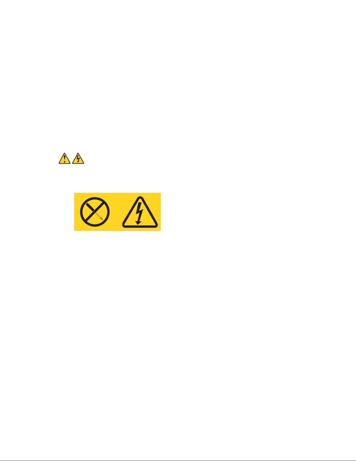
Statement 5:
xxCAUTION:
Never remove the cover on a power supply or any part that has the following label attached.
Hazardous voltage, current, and energy levels are present inside any component that has this
label attached. There are no serviceable parts inside these components. If you suspect a
problem with one of these parts, contact a service technician.
viii
Page 9
Statement 6:
DANGER
Overloading a branch circuit is potentially a fire hazard and a shock hazard under
certain conditions. To avoid these hazards, ensure that your system electrical
requirements do not exceed branch circuit protection requirements. Refer to the
Statement 7:
xxCAUTION:
Hazardous voltage, current, and energy levels might be present. Only a qualified service
technician is authorized to remove the covers where the following label is attached.
ix
Page 10

x
Page 11

1 Introducing the Intel® Blade Server Ethernet
Switch Module IXM5414E
Thank you for purchasing an Intel® Blade Server Ethernet Switch Module IXM5414E. This
Installation and User’s Guide contains information about:
• Setting up and installing your switch module
• Configuring your switch module
For installation details, see Chapter 2 “Installing and Removing the Intel® Blade Server Ethernet
Switch Module IXM5414E” on page 9. For additional information, see the instructions in your
appropriate server board chassis publications.
Your IXM5414E switch module is one of up to four switch modules that can be installed in the
SBCE configuration of the blade chassis.
This high-performance IXM5414E switch module is ideally suited for networking environments that
require superior microprocessor performance, efficient memory management, flexibility and reliable
data storage.
Performance, reliability and expansion capabilities were key considerations in the design of your
switch module. These design features make it possible for you to customize the system hardware to
meet your needs today, while providing flexible expansion capabilities for the future.
The product name, machine type and serial number are located on the identification label on the side
of the IXM5414E switch module. The Media Access Control (MAC) address also is located on the
identification label. See
illustration showing the location of the identification label.
“Major components of the IXM5414E switch module” on page 3 for an
/ NOTE
The MAC address is also located on a separate label on the information panel under the
external Ethernet port connectors.
1
Page 12

Record your product information in this table.
Product name Intel® Blade Server Ethernet Switch Module IXM5414E
Type _________________________________________________
Model number _________________________________________________
Serial number _________________________________________________
Media access
control (MAC)
address
Verify that the shipping carton contains an Intel® Blade Server Ethernet Switch Module IXM5414E.
If the switch module is missing or damaged, contact your local reseller for replacement. Otherwise,
return the switch module to its static-protective package.
/ NOTE
The illustrations in this document may differ slightly from your hardware.
_________________________________________________
Related publications
This Installation and User’s Guide contains setup and installation instructions for your IXM5414E
switch module. This publication also provides general information about your switch module,
including getting started and how to configure the switch module.
In addition to this Installation and User’s Guide, the Intel® Server Boards and Server Chassis Safety
Information is included with your switch module. This multilingual publication is provided in PDF
on the Resource CD. It contains translated versions of the caution and danger statements that appear
in the documentation.
Depending on your switch model, additional publications might be included on the Resource CD.
2 Intel® Blade Server Ethernet Switch Module IXM5414E
Page 13

Notices and statements used in this book
The caution and danger statements that appear in this book are also in the multilingual Safety
Information Book on the Resource CD. Each statement is numbered to refer to the corresponding
statement in the Safety Information Book.
The following notices and statements are used in this book:
• Note: These notices provide important tips, guidance or advice.
• Important: These notices provide information or advice that might help you avoid inconvenient
or problematic situations.
• Attention: These notices indicate possible damage to programs, devices or data. An attention
notice is placed just before the instruction or situation in which damage could occur.
• Caution: These statements indicate situations that can be potentially hazardous to you. A
caution statement is placed just before the description of a potentially hazardous procedure, step
or situation.
• Danger: These statements indicate situations that can be potentially lethal or extremely
hazardous to you. A danger statement is placed just before the description of a potentially lethal
or extremely hazardous procedure, step or situation.
Major components of the IXM5414E switch module
The green on components and labels on your IXM5414E switch module and on the platform
identifies hot-swap or hot-plug components. You can install or remove these components while the
system is running, provided that your system is configured to support this function.
The blue color on components and labels indicates touch points where a component can be gripped,
a latch can be moved, and so on.
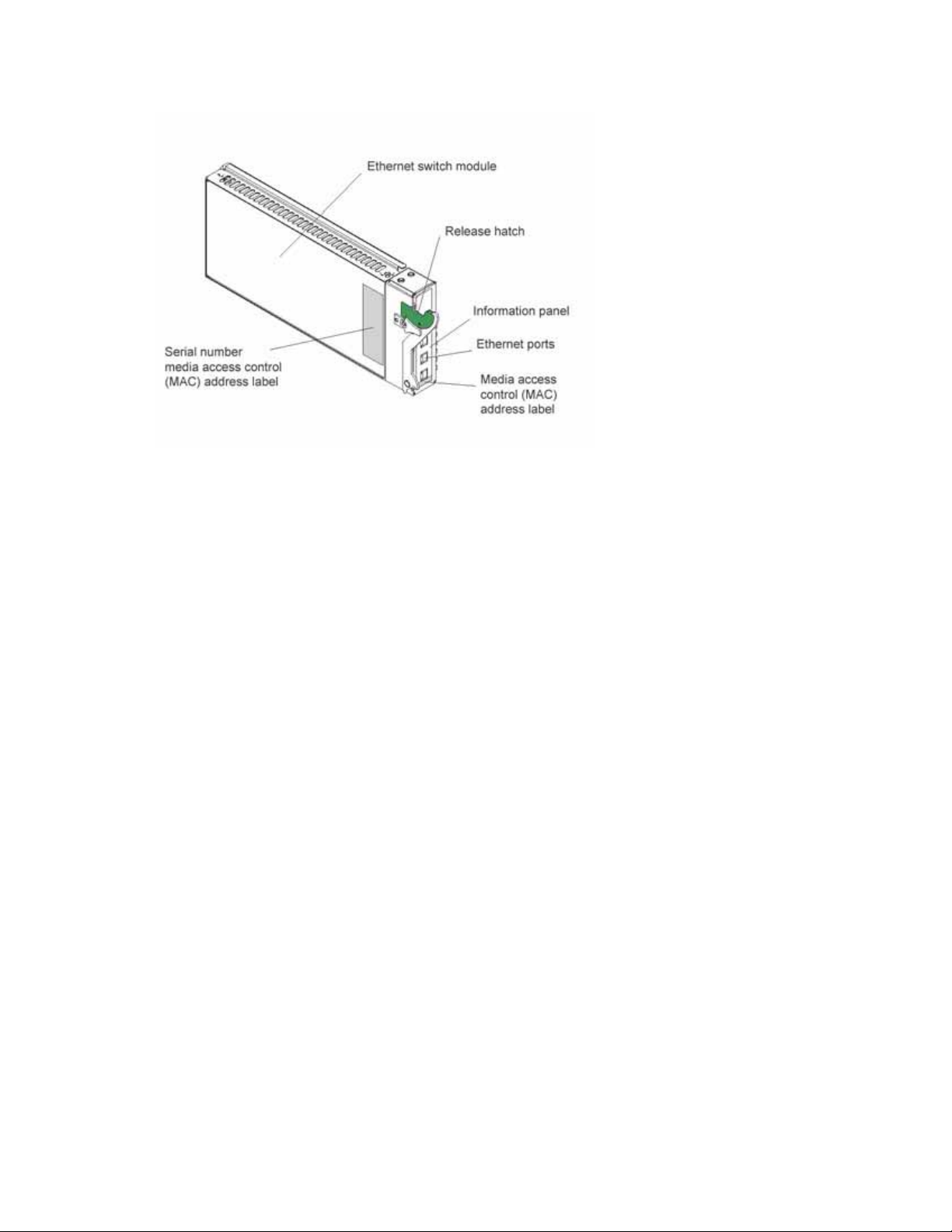
The following illustration shows the major components of your switch module.
/ NOTE
The illustrations in this document may differ slightly from your hardware.
Intel® Blade Server Ethernet Switch Module IXM5414E 3
Page 14
For more information about the components of the information panel, see Chapter 3 “Information
Panel LEDs and External Ports” on page 17. For more information about the MAC address, see “IP
addresses and SNMP community names” on page 21.
Specifications and features
The following section provides a summary of the specifications and features for your IXM5414E
switch module.
• Ports
— Four external 1000BASE-T ports for making 10/100/1000 Mbps connections to a backbone,
end stations, and servers
— Fourteen internal full-duplex gigabit ports, one connected to each of the blade servers
— Two internal full-duplex 100 Mbps ports connected to the management modules
• Performance features
— Transmission method: Store-and-forward
— Packet filtering/forwarding rate
– Full-wire speed for all connections
• 148k packets per second per port (for 100 Mbps)
• 1.48m packets per second (pps) per port (for 1000 Mbps)
— Media Access Control (MAC) address learning: Automatic update. Supports 3584 MAC
address.
— Forwarding table age time: Maximum age: 10 to 1,000,000 seconds. Default is 300 seconds
— Support for 128 concurrent VLANs
— Switch Topology: Star
4 Intel® Blade Server Ethernet Switch Module IXM5414E
Page 15

• Standards
The following standards apply to the IXM5414E switch module.
— Switching Support
– IEEE 802.3 10BASE-T Ethernet
– IEEE 802.3 Auto-negotiation
– IEEE 802.3u 100BASE-TX Fast Ethernet
– IEEE 802.3z Gigabit Ethernet
– IEEE 802.3ab 1000BASE-T
– IEEE 802.1Q Tagged VLAN
– IEEE 802.1p Priority
– GARP
–GMRP
– GVRP
– IEEE 802.3ac - VLAN Tagging
– IEEE 802.3ad - Link Aggregation
– IEEE 802.1s - Spanning Tree
– IEEE 802.1w - Rapid Spanning Tree
– IEEE 802.1X - Port Based Authentication
– IEEE 802.3X - Flow Control
– RFC 768 - UDP
– RFC 783 - TFTP
– RFC 791 - IP
– RFC 792 - ICMP
– RFC 793 - TCP
– RFC 826 - ARP
– RFC 1321 - Message Digest Algorithm
– RFC 2131 - DHCP Client
– RFC 2865 - RADIUS Client
• RFC 2866 - RADIUS Accounting
• RFC 2868 - RADIUS Attributes for Tunnel Protocol Support
• RFC 2869 - RADIUS Extensions
• RFC 2869bis - RADIUS Support for Extensible Authentication Protocol (EAP)
– Advanced Layer 2 Functionality:
• Broadcast Storm Recovery
• Multicast Storm Recovery
Intel® Blade Server Ethernet Switch Module IXM5414E 5
Page 16

• Independent VLAN Learning (IVL) support
• Port Mirroring
• IGMP Snooping
• Static MAC Filtering
– System Facilities
• Event and Error Logging Facility
• Run-time and Configuration Download Capability
• PING Utility
— Quality of Service (QOS) Support
– Bandwidth Provisioning
• Maximum Burst Rate (MBR)
• Per Port (Interface)
• Per VLAN
– Access Control Lists
• Source IP
• Destination IP
• Source L4 Port
• Destination L4 Port
• Management
— RMON - Groups 1, 2, 3 and 9 supported
— Simple Network Management Protocol (SNMP) versions 1, 2 and 3
— Flash memory for software upgrades, done using Trivial File Transfer Protocol (TFTP)
— Supports Web-based management
– HTML 4.0 Specification - December, 1997
– Java Script 1.3
–Java 1.3
– RFC 2068 - HTTP/1.1 protocol as updated by draft-ierf-http-v11-spec-rev-03
– HTML/2.0 Forms with file upload extensions
— Command Line Interface (CLI) with the following features
– Scripting capability
– Command completion
– Context sensitive help
– Multi-session Telnet Server
— RFC 854 - Telnet
— RFC 855 - Telnet Option
6 Intel® Blade Server Ethernet Switch Module IXM5414E
Page 17

— RFC 1155 - SMI v1
— RFC 1157 - SNMP
— RFC 1212 - Concise MIB Definitions
— RFC 1901 - Community-based SNMP v2
— RFC 1905 - Protocol Operations for SNMP v2
— RFC 1906 - Transport Mappings for SNMP v2
— RFC 1907 - Management Information Base for SNMP v2
— RFC 1908 - Coexistence between SNMP v1 and SNMP v2
— RFC 2295 - Remote Variant Selection; RSVA/1.0 State Management “cookies” - draft-ietf-
http-state-mgmt-05
— RFC 2571 - Architecture for Describing SNMP Management Frameworks
— RFC 2572 - Message Processing and Dispatching for SNMP
— RFC 2573 - SNMP v3 Applications
— RFC 2574 - User Based Security Model for SNMP v3
— RFC 2575 - View-based Access Control Model for SNMP
— RFC 2576 - Coexistence between SNMP v1, v2, and v3
— RFC 2580 - Conformation statements for SMI v2
— Configurable management VLAN
– Secure Socket Layer (SSL) 3.0 and Transport Layer Security (TLS) 1.0
• RFC 2246 - The TLS Protocol, Version 1.0
• RFC 2818 - HTTP over TLS
• RFC 2346 - AES Ciphersuites for TLS
– Secure Shell (SSH) 1.5 and 2.0
• Draft-ietf-secsh-transport-16 - SSH Transport Layer Protocol
• Draft-ietf-secsh-userauth-17 - SSH Authentication Protocol
• Draft-ietf-secsh-connect-17 - SSH Connection Protocol
• Draft-ietf-secsh-architecture-14 - SSh Protocol Architecture
• Draft-ietf-secsh-publickeyfile-03 - SECSH Public Key File Format
• Draft-ietf-secsh-dh-group-exchange-04 - Diffie-Hellman Group Exchange for the
SSH Transport Layer Protocol
— MIBs Supported
– Switching MIBs
• RFC 1213 - MIB-II
• RFC 1493 - Bridge MIB
• RFC 1643 - Ethernet-like MIB
Intel® Blade Server Ethernet Switch Module IXM5414E 7
Page 18

• RFC 2674 - VLAN MIB
• RFC 2618 - RADIUS Authentication Client MIB
• RFC 2620 - RADIUS Accounting MIB
• RFC 2819 - RMON Groups 1, 2, 3 and 9
• IEEE 802.1X MIB (IEEE 802.1-PAE-MIB)
• Enterprise MIB
– QOS / SNMP Support in Enterprise MIBs
• Available through Management Module
• Private MIBs for full configuration of ACL and Bandwidth Provisioning
• Network Cable Support
— 10BASE-T
– UTP Category 3, 4, 5 (100 meters maximum)
– 100-ohm STP (100 meters maximum)
functionality
— 100BASE-TX
– UTP Category 5 (100 meters maximum)
– EIA/TIA-568 100-ohm STP (100 meters maximum)
— 1000BASE-T
– UTP Category 5e (100 meters maximum)
– UTP Category 5 (100 meters maximum)
– EIA/TIA-568B 100-ohm STP (100 meters maximum)
8 Intel® Blade Server Ethernet Switch Module IXM5414E
Page 19
2 Installing and Removing the Intel® Blade
Server Ethernet Switch Module IXM5414E
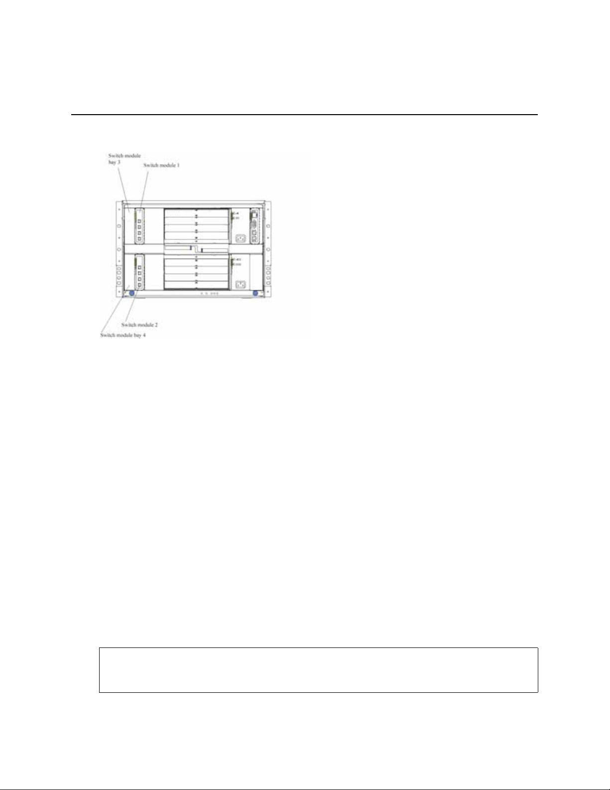
The following illustration shows the I/O module bay locations in the SBCE platform.
Attention: To maintain proper system cooling, each I/O module bay must contain either a module
or a filler module; each blade bay must contain either a blade or a filler blade.
Ethernet interface requirements
The SBCE platform supports a minimum of one hot-swap Ethernet switch module in I/O module
bay 1. This switch module is a fully functional four-connector Ethernet switch that provides a
network connection to Ethernet Link 1 in all the blade servers in the SBCE. To provide a network
connection for Ethernet Link 2 in each blade server, install an Ethernet switch module in I/O module
bay 2.
If you install an interface option on any blade server, you must install a hot-swap switch module of
the same interface type in I/O module bay 3 to obtain connection 1 for the interface option. To
provide connection 2 for the interface option, install a switch module of that interface type in I/O
module bay 4. The switch modules in I/O module bays 3 and 4 provide connections to all the
interface options in the SBCE.
Important: The switch modules in I/O module bays 3 and 4 and all blade server interface options in
the SBCE must use the same interface type. For example: if you install an Ethernet interface option
on a blade server, the switch modules that you install in I/O module bays 3 and 4 must be Ethernet.
All other interface options in the SBCE must also be Ethernet interface options.
The following table summarizes the application for each switch module.
I/O module
bay
1 Connection 1 (Ethernet Link 1) for all blade servers in the SBCE
Switch-module function
9
Page 20

I/O module
bay Switch-module function
2 Connection 2 (Ethernet Link 2) for all blade servers in the SBCE
3 Connection 3 (from all blade server interface options in the SBCE)
4 Connection 4 (from all blade server interface options in the SBCE)
For additional information, see the Intel® Blade Server Chassis SBCE : Installation and User’s
Guide on the Resource CD.
Installation guidelines
Before you begin installing the IXM5414E switch module in your SBCE, read the following
information:
• Become familiar with the safety and handling guidelines specified under Appendix H “Notices”
on page 277 and “Handling static-sensitive devices”, and read the safety statements in the SBCE
option publications.
• The green color on components and labels in your SBCE identifies hot-swap or hot-plug
components. You can install or remove hot-swap modules while the SBCE is running. For
complete details about installing or removing a hot-swap or hot-plug component, see the
detailed information in this chapter.
• The blue color on components and labels identifies touch points where you can grip a
component, move a latch, and so on.
• You do not need to turn off the SBCE to install or replace any of the hot-swap modules on the
rear of the SBCE.
System reliability considerations
Attention: To help ensure proper cooling and system reliability, make sure that:
• Each of the I/O module bays on the rear of the SBCE has either a module or filler module
installed.
• A removed hot-swap module is replaced with an identical module or filler module within 1
minute of removal.
• Cables for the optional modules are routed according to the illustrations and instructions in this
document.
Handling static-sensitive devices
Attention: Static electricity can damage electronic devices and your system. To avoid damage,
keep static-sensitive devices in their static-protective packages until you are ready to install them.
To reduce the possibility of electrostatic discharge, observe the following precautions:
• Limit your movement. Movement can cause static electricity to build up around you.
• Handle the device carefully, holding it by its edges or its frame.
• Do not touch solder joints, pins, or exposed printed circuitry.
10 Intel® Blade Server Ethernet Switch Module IXM5414E
Page 21
• Do not leave the device where others can handle and possibly damage it.
• While the device is still in its static-protective package, touch it to an unpainted metal part of the
SBCE platform for at least two seconds. (This drains static electricity from the package and
from your body.)
• Remove the device from its package and install it directly into your SBCE without setting it
down. If it is necessary to set the device down, place it in its static-protective package. Do not
place the device on your SBCE platform or on a metal table.
• Take additional care when handling devices during cold weather because heating reduces indoor
humidity and increases static electricity.
Installing the IXM5414E switch module
Statement 8:
xxCAUTION:
Never remove the cover on a power supply or any part that has the following label attached.
Hazardous voltage, current, and energy levels are present inside any component that has this
label attached. There are no serviceable parts inside these components. If you suspect a
problem with one of these parts, contact a service technician.
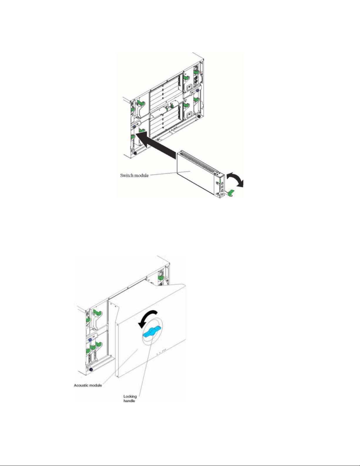
The following illustrations show how to install a switch module in the rear of the SBCE platform.
Intel® Blade Server Ethernet Switch Module IXM5414E 11
Page 22
SBCE
Complete the following steps to install the IXM5414E switch module.
1. Review the information in “Safety” on page v and in “Installation guidelines” on page 10.
2. Remove the acoustic attenuation module, if installed, from the rear of the SBCE platform. The
following illustrations show how to remove the module from the SBCE platform.
12 Intel® Blade Server Ethernet Switch Module IXM5414E
Page 23
3. Select an I/O module bay in which to install the switch module, in accordance with the
instructions in
“Ethernet interface requirements” on page 9.
4. Remove the filler module from the selected I/O module bay. Store the filler module for future
use.
5. If you have not already done so, touch the static-protective package that contains the switch
module to an unpainted metal part of the SBCE platform for at least two seconds.
6. Remove the switch module from its static-protective package.
7. Ensure that the release latch on the switch module is in the open position (perpendicular to the
module).
8. Slide the switch module into the appropriate I/O module bay until it stops.
9. Push the release latch on the front of the switch module to the closed position.
10. Make sure that the LEDs on the switch module indicate that it is operating properly. Verify that:
• The DC power LED and the ac power LED on each power module are lit.
• The OK LED on each management module is lit.
• The OK LED on each switch module is lit.
11. If you have other switch modules to install, do so now; otherwise, continue with the next step.
12. Attach any cables required by the switch module. For the location of the connectors on the
SBCE platform, see Intel® Server Chassis SBCE Installation and User’s Guide on the Resource
CD.
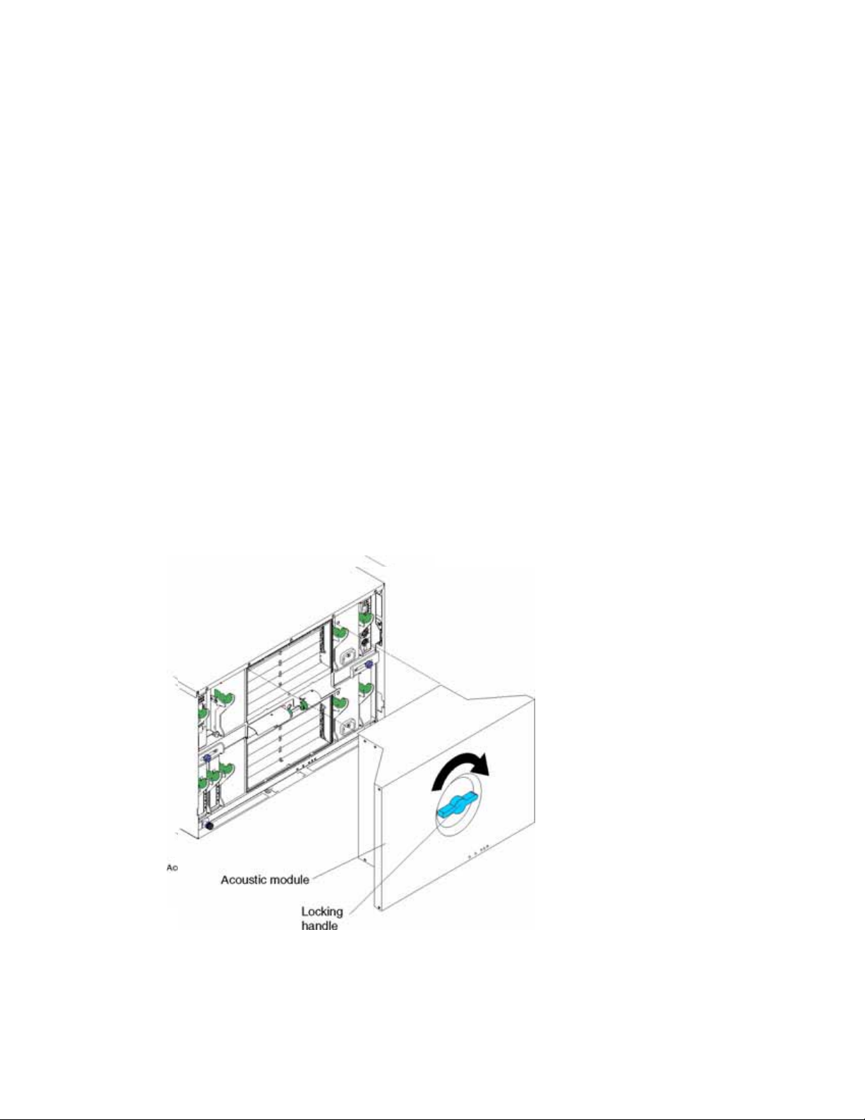
13. Replace the acoustic attenuation module if you removed it in Step 2. The following illustration
shows how to replace the acoustic attenuation module in the SBCE platform.
Intel® Blade Server Ethernet Switch Module IXM5414E 13
Page 24

Removing the IXM5414E switch module
Statement 8:
xxCAUTION:
Never remove the cover on a power supply or any part that has the following label attached.
Hazardous voltage, current, and energy levels are present inside any component that has this
label attached. There are no serviceable parts inside these components. If you suspect a
problem with one of these parts, contact a service technician.
Complete the following steps to remove the IXM5414E switch module.
1. Select an appropriate I/O module bay from which to remove a switch module, in accordance
with the instructions in
2. Unplug any cables from the selected switch module.
3. For the SBCE platform, pull the release latch toward the side of the switch module as shown in
the illustration below. The module moves out of the I/O module bay about 0.64 cm (0.25 inch).
“Ethernet interface requirements” on page 9.
SBCE
14 Intel® Blade Server Ethernet Switch Module IXM5414E
Page 25

4. Slide the switch module out of the I/O module bay and set it aside.
5. Place either another switch module or a filler module in the I/O module bay within 1 minute.
6. If you placed another switch module in the I/O module bay, reconnect any cables that you
unplugged in Step 2.
7. Replace the acoustic attenuation module option if you removed it in step 1.
Intel® Blade Server Ethernet Switch Module IXM5414E 15
Page 26

16 Intel® Blade Server Ethernet Switch Module IXM5414E
Page 27

3 Information Panel LEDs and External Ports
This chapter describes the information panel and LEDs (also known as indicators) on the Intel®
Blade Server Ethernet Switch Module IXM5414E. This chapter also identifies the external ports on
the information panel.
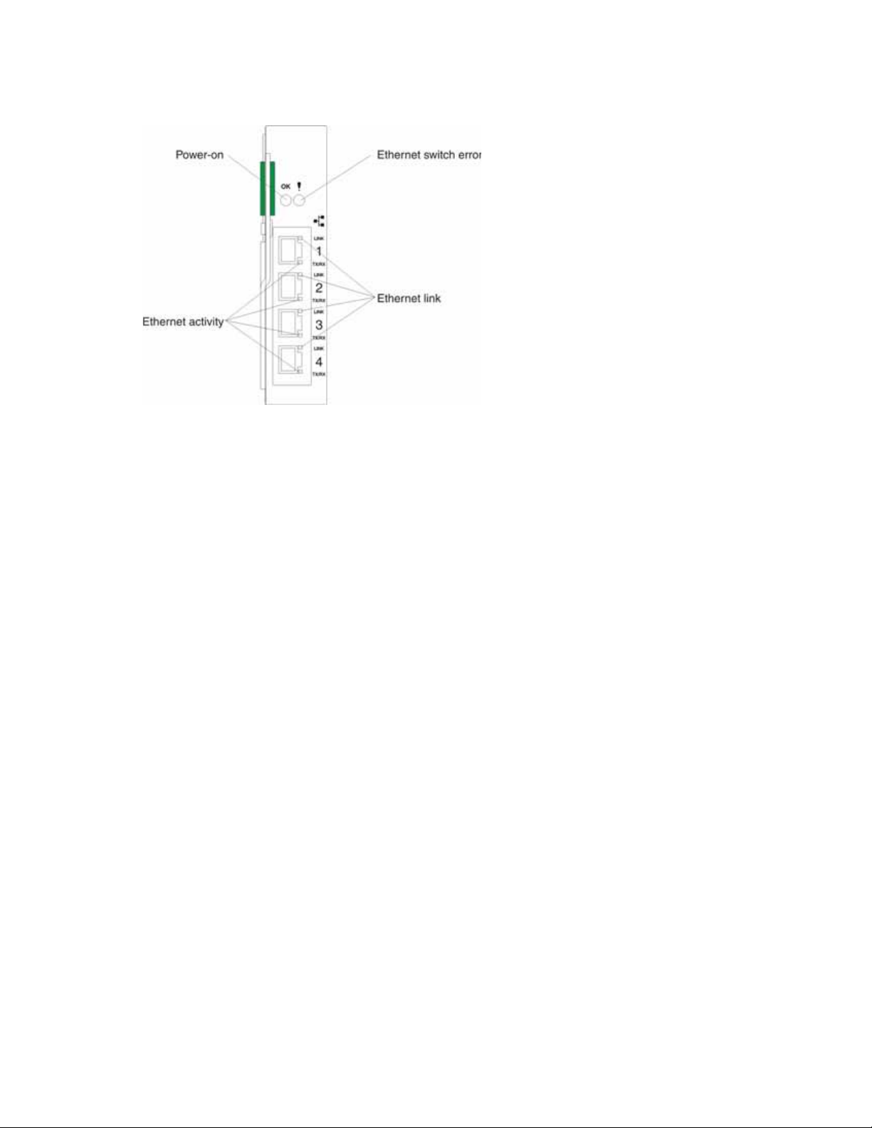
Information panel
The information panel of the IXM5414E switch module consists of LEDs and four external
1000BASE-T ports, as shown in the following illustration.
LEDs
OK
LINK
1
TX/RX
LINK
Por ts
TX/RX
LINK
TX/RX
LINK
TX/RX
2
3
4
LEDs
HHampton -T
The Intel® Blade Server Ethernet Switch Module IXM5414E contains:
• Comprehensive LEDs, which display the status of the switch module and the network (see
“LEDs”).
• Fourteen internal ports, one connected to each of the processor blades.
• Two internal full-duplex 10/100 Mbps ports connected to the management module.
• Four external 1000BASE-T Ethernet ports for 10/100/1000 Mbps connections to external
Ethernet devices such as backbones, end stations and servers. These ports are identified as Ext1,
Ext2, Ext3 and Ext4 in the switch configuration menus and are labeled 1 through 4 (from top to
bottom) on the switch module, as shown in the preceding illustration.
LEDs
The LEDs on the information panel of the IXM5414E switch module include OK, !, Ethernet link,
and Ethernet activity. The following illustration shows the LEDs on the switch module. A
description of each LED follows the illustration.
17
Page 28
Notes:
1. The illustrations in this document may differ slightly from your hardware.
2. An amber LED illuminates when a system error or event has occurred. To identify the error or
event, check the LEDs on the information panel of the switch module.
OK (power-on): This green LED is located above the four external 10/100/1000 Mbps ports on the
information panel. When this LED is on, it indicates that the switch module has passed the PowerOn Self-Test (POST) and is operational.
! (Ethernet switch error): This amber LED is located next to the OK (power-on) LED on the
information panel. This LED indicates that the switch module has a fault. If the switch module fails
the POST, this fault LED will be lit.
Ethernet link: This green link status LED is located at the top of each external 10/100/1000 Mbps
port. When this LED is lit on a port, it indicates that there is a connection (or link) to a device on that
port.
Ethernet activity: This green activity LED is located at the bottom of each external 10/100/1000
Mbps port. When this LED blinks on a port, it indicates that data is being received or transmitted
(that is, activity is occurring) on that port. The blink frequency is proportional to the amount of
traffic on that port.
18 Intel® Blade Server Ethernet Switch Module IXM5414E
Page 29

4 Switch Management and Operating Concepts
This chapter discusses many of the concepts and features used to manage the Intel® Blade Server
Ethernet Switch Module IXM5414E and the concepts necessary to understand how it functions. In
addition, this chapter explains many important points regarding these features.
Configuring the switch module to implement these concepts and use its many features is discussed
in detail in the following chapters.
Intel® Blade Server Ethernet Switch Module IXM5414E
overview
This section provides information that you should be familiar with when managing and configuring
the internal switch modules. If you are familiar with Ethernet switches, you will recognize the
industry-standard parameters and terminology used in this document. However, it is important that
you also understand the operating environment of the SB-HE platform with regard to the internal
switches.
IXM5414E switch modules are hot-swappable subsystems that provide Ethernet switching
capabilities within the chassis of the SB-HE platform. The primary purpose of the switch module is
to provide Ethernet interconnectivity among the processor blades, management modules and the
external network infrastructure.
The SB-HE platform may be configured with up to four independent switch modules, supporting up
to fourteen server blades. Ports 1 through 14 on the switch module correspond to server blades 1
through 14, respectively (numbered left to right when viewed from the front of the chassis). Each
switch module has four external 10/100/1000 Mbps Ethernet ports for connection to the external
network infrastructure. These ports are identified as Ext.1, Ext.2, Ext.3 and Ext.4 in the switch
module configuration menus and are labeled 1 through 4 on the switch module (see Chapter
3 “Information Panel LEDs and External Ports” on page 17 for an illustration).
Depending on the application, the external Ethernet interfaces can be configured to meet a variety of
requirements for bandwidth or function.The IXM5414E switch module has been pre-configured
with default parameter settings that can be used with some typical installations. Most installations
will need some configuration of parameters. Information on initial software configuration can be
found in
module system commands” on page 160.
“Remotely managing the IXM5414E switch module” on page 158 and “IXM5414E switch
Chassis configuration and operation
Each IXM5414E switch module is an integral subsystem within an overall SB-HE platform. For
additional platform level information, see the applicable Installation and User’s Guide publications
on the Resource CD. Each chassis includes one or two management modules (MM) as the central
element for overall chassis management and control. The switch module includes 100-Mbps internal
Ethernet ports that can only be accessed by the management modules. To prevent inadvertent
changes, this management port is “hidden” and does not appear in the port configuration and status
screens. The factory default settings will only permit management and control access to the switch
module through the 10/100 Mbps Ethernet port on the management module. You can use the four
external 10/100/1000 Mbps Ethernet ports on the switch module for management and control of the
19
Page 30

module by selecting this mode as an option through the management module configuration utility
program (see the applicable Installation and User’s Guide publications on the Resource CD for more
information).
Switch module management and control
This document describes the user interfaces, screens, parameters and other information that you need
for remote management and control of your IXM5414E switch module. Complete the following initial
configuration steps:
1. Connect the Ethernet port of the management module to a 10/100 Mbps network (with access to a
management station) or directly to a management station.
2. Initially configure the management module with the appropriate IP addresses for network access
(see the applicable SB-HE Installation and User’s Guide publications on the Resource CD for more
information).
3. From the management-module Web interface, click I/O Module Tasks, click Management; then,
click the bay in which the switch module is installed.
4. Click Advanced Management under the selected bay and make sure that the following Ethernet
switch module features are enabled:
• External ports
• External management over all ports
• Preserve new IP configuration on all resets
5. Click Save.
Note: When management of the Ethernet switch module is enabled through the four external ports,
the switch module will acquire its IP address from a Dynamic Host Configuration Protocol (DHCP)
server when the switch module is turned on or reset.
Once a transmission control protocol/Internet protocol (TCP/IP) communication path has been
established with the switch module through the Management Module’s Ethernet port, you can perform
a series of management and control tasks. These tasks are in the following categories:
• Configuration
• Modification of the switch module’s parameter settings
• Remote management setup
• Network monitoring
— Automatically receive error alerts (traps)
— View/reset port traffic statistics
— Monitor data traffic on selected output ports
• Maintenance
— Update the switch module’s software
— View and configure the message and event logs
— Restore factory default settings
The switch module supports three primary management and control user interfaces. A built-in Web
browser interface is the primary interface (see Chapter
41 for detailed information). The Web browser interface can be invoked from the management and
configuration utility program, along with the Telnet interface that provides a Command Line Interface
20 Intel® Blade Server Ethernet Switch Module IXM5414E
5 “Web-Based Network Management” on page
Page 31

(CLI) (see Chapter 7 “Command Line Interface Management” on page 155 for detailed information).
Both interfaces provide access to the same switch information and control parameters.
In addition, you can access an extensive set of both standard and private MIB objects through SNMP
protocols.
IP addresses and SNMP community names
Each switch module must be assigned its own Internet protocol (IP) address, which is used for
communication with a Simple Network Management Protocol (SNMP) network manager or other
transmission control protocol/Internet protocol (TCP/IP) application. The switch module default IP
address is 10.90.90.9x, where x depends on the number of the I/O module bay into which you have
installed the switch module, as shown in Table 1.
Table 1. Default IP addresses based on I/O module bay numbers
I/O module bay number Default IP address
Switch Module Bay 1 10.90.90.91
Switch Module Bay 2 10.90.90.92
Switch Module Bay 3 10.90.90.94
Switch Module Bay 4 10.90.90.97
The following illustration shows the I/O module bay locations.
You can change the default switch module IP address to meet the requirements of your networking
address scheme.
The switch module also has a unique, factory-assigned media access control (MAC) address. The
switch module MAC address is located on one side of the switch module, on the same label as the serial
number, as shown in the following illustration.
/ NOTE
The MAC address is also located on a separate label on the information panel under the external
Ethernet port connectors.
Intel® Blade Server Ethernet Switch Module IXM5414E 21
Page 32

The switch MAC address can also be displayed using CLI command show inventory or from the
Web Interface.
In addition, you can also set an IP address for a gateway router. This becomes necessary when the
network management station and switch modules are located on different IP networks, requiring
management packets to go through a router to reach the network manager.
For security, you can specify the IP addresses of the network managers that are permitted to manage
the switch module using the config snmpcommunity ipaddr CLI command or the Web Interface
equivalent. You can also change the default SNMP community strings in the switch module and set
the access rights of these community strings.
Traps
Traps are messages that alert you of certain events that occur on the switch module. The events can
be as serious as a restart (for example, someone accidentally turned off the switch module) or less
serious, such as a port-status change. The switch module generates traps and sends them to the
network manager (trap recipient).
Trap recipients are special users of the network who are given certain rights and access to oversee
the maintenance of the network. Trap recipients will receive traps sent from the switch module; they
may then need to take certain actions to avoid future failure or breakdown of the network.
You can also specify which network managers can receive traps from the switch module by entering
a list of the IP addresses of authorized network managers. You can enter up to four trap recipient IP
addresses and four corresponding SNMP community strings.
SNMP community strings function like passwords in that the community string entered for a given
IP address must be used in the management station software, otherwise a trap will be sent.
The following are trap types that the switch module can send to a trap recipient:
Cold start This trap indicates that the switch module has been turned on and initialized such
that software settings are reconfigured and hardware systems are restarted. A cold
start is different from a factory reset in that configuration settings saved to
22 Intel® Blade Server Ethernet Switch Module IXM5414E
Page 33

nonvolatile random-access memory (NVRAM) are used to reconfigure the switch
module.
Warm start This trap indicates that the switch module has been restarted; however, the power-
on self-test (POST) is skipped.
Authentication failure
This trap indicates that someone has tried to log on to the switch module using an
invalid SNMP community string. The switch module automatically stores the
source IP address of the unauthorized user.
Topology change (Spanning Tree Protocol (STP))
This trap indicates that one or more of the configured ports has changed from the
learning state to the forwarding state, or from the forwarding state to the blocking
state.
Link up This trap indicates that the link state of a port has changed from link down to link
up.
Link down This trap indicates that the link state of a port has changed from link up to link
down.
Management Information Bases (MIB)
Management and counter information are stored in the switch module in the management
information base (MIB). The switch module uses the standard MIB-II management information base
module. Consequently, values for MIB objects can be retrieved using any SNMP-based network
management software. In addition to the standard MIB-II module, the switch module also supports
its own proprietary enterprise MIB as an extended management information base. This MIB can also
be retrieved by specifying the object identifier (OID) of the MIB as the network manager. MIB
values can be either Read-only or Read/Write.
Read-only MIB variables can be either constants that are programmed into the switch module or
variables that change while the switch module is in operation. Examples of Read-only constants are
the number of ports and type of ports. Examples of Read-only variables are the statistics counters,
such as the number of errors that have occurred, or how much data (in kilobytes) has been received
and forwarded through a port.
Read/Write MIBs variables are usually related to user-customized configurations. Examples of these
are the switch module IP address, Spanning Tree Protocol (STP) parameters and port status.
If you use a third-party vendor’s SNMP software to manage the switch module, a diskette listing the
switch module proprietary enterprise MIBs can be obtained by request. If your software provides
functions to browse or modify MIBs, you can also get the MIB values and change them (if the
attributes of the MIBs permit the write operation). However, this process can become complicated,
because you must know the MIB OIDs and retrieve them one by one.
Port mirroring
The IXM5414E switch module enables you to copy packets that were transmitted and received on a
source port and to redirect the copies to another target port. The source port can be either one of the
four 10/100/1000 Mbps external ports, or one of the fourteen internal blade server ports. The target
port is where you will connect a monitoring/troubleshooting device, such as a sniffer or an RMON
probe. The target port must be one of the four 10/100/1000 Mbps external ports.
Intel® Blade Server Ethernet Switch Module IXM5414E 23
Page 34

You can attach a monitoring device to the mirrored port, such as a sniffer or an RMON probe, to
view details about the packets that pass through the first port. This is useful for network monitoring
and troubleshooting purposes.
Simple Network Management Protocol (SNMP)
The Simple Network Management Protocol (SNMP) is an open system interconnection (OSI) layer
7 (application layer) protocol for remotely monitoring and configuring network devices. SNMP
enables network management stations to read and modify the settings of gateways, routers, switches
and other network devices. SNMP can be used to perform many of the same functions as a directly
connected console, or can be used within an integrated network management software package such
as
IBM® NetView or Hewlett Packard OpenView. SNMP performs the following functions:
• Sending and receiving SNMP packets using the IP protocol
• Collecting information about the status and current configuration of network devices
• Modifying the configuration of network devices
The switch module has a software program, called an agent, that processes SNMP requests, but the
user program that makes the requests and collects the responses runs on a management station (a
designated computer on the network). The SNMP agent and the user program both employ the user
datagram protocol/Internet protocol (UDP/IP) to exchange packets.
Authentication
The authentication protocol ensures that both the SNMP agent in the switch module and the remote
user SNMP application program discard packets from unauthorized users. Authentication is
accomplished by using community strings which function like passwords. The remote user SNMP
application and the switch module’s SNMP agent must use the same community string. SNMP
community strings of up to 20 characters can be entered using the CLI snmp community commands
described in Chapter
7 “Command Line Interface Management” on page 155.
Switching concepts
This section introduces the concepts and protocols relevant to the switching functionality of the
Intel® Blade Server Ethernet Switch Module IXM5414E.
Packet forwarding
The switch module uses a forwarding table to store the information that it collects about the location
of devices on the network. The table holds destination MAC addresses and the destination port
number through which they can be reached. Packets sent to known addresses are therefore
transmitted only through relevant destination ports, thus reducing network traffic. For example, if
port 1 receives a packet destined for a station on port 2, the switch module transmits that packet
through port 2 only and transmits nothing through the other ports. Creating the table is referred to as
learning the network topology.
An aging timer is used to make sure that the table is updated if devices are moved. Dynamic entries,
those learned by the switch by observing network traffic, are deleted from the table if they are not
accessed within the aging time. Static entries, those entered by a network administrator, are not
subject to the aging process.
24 Intel® Blade Server Ethernet Switch Module IXM5414E
Page 35

The aging time can be from 10 to 1,000,000 seconds, with a default value of 300 seconds. Setting the
value too high could mean that some entries in the table become out of date, causing the switch
module to make incorrect packet-forwarding decisions. If the aging time is too short, however,
entries may be aged out too soon and have to be relearned. While the entries are being relearned,
received packets whose source addresses cannot be found in the forwarding table will be transmitted
through all ports on the switch, thus unnecessarily increasing network traffic.
Spanning Tree Protocol (STP)
The Institute of Electrical and Electronics Engineers (IEEE) 802.1D Spanning Tree Protocol (STP)
enables the blocking of links between switches that form loops within the network. When multiple
links between switches are detected, a primary link is established. Duplicated links are blocked from
use and become standby links. The protocol enables the duplicate links to be used in the event of a
failure of the primary link. When the STP is configured and enabled, primary links are established,
and duplicated links are blocked automatically. The reactivation of the blocked links (at the time of a
primary link failure) is also accomplished automatically, without operator intervention.
This automatic network reconfiguration provides maximum uptime to network users. However, the
concepts of the Spanning Tree Algorithm and Protocol are complicated and complex subjects and
must be fully researched and understood. It is possible to cause serious degradation of the
performance of the network if the spanning tree is incorrectly configured. Read the following
information before making any changes from the default values.
The switch module STP performs the following functions:
• Creates a single spanning tree from any combination of switching or bridging elements
• Automatically reconfigures the spanning tree to compensate for the failure, addition or removal
of any element in the tree
• Reconfigures the spanning tree without operator intervention
Improper configuration of the switch module’s external ports or improper cabling of the external
ports to another switch device can create duplicate links that might cause network loops. Consult
your network administrator for details about the configuration requirements for your system.
The single spanning tree created by the Spanning Tree Algorithm is referred to as the Common
Spanning Tree (CST) in some of the commands described in this document.
The original Spanning Tree Algorithm defined in IEEE 802.1D has been updated to allow for faster
reconfiguration in the event of a change to network topology or configuration parameters. This new
protocol is defined in IEEE 802.1w as Rapid Reconfiguration and is based on the ability of the
bridging device to recognize ports which are full-duplex and ports which are connected directly to
end stations. The IEEE 802.1 standards committee recommends the use of IEEE 802.1w in
preference to IEEE 802.1D, except when running certain protocols (e.g. LLC2 and NETBEUI) that
are sensitive to the slightly increased probability of frame misordering. The IXM5414E switch
module defaults to IEEE 802.1D operation, but can be configured to use the algorithm and protocols
defined in IEEE 802.1w instead.
IEEE 802.1D has been further revised in IEEE 802.1s, which incorporates IEEE 802.1w and defines
a multiple Spanning Tree Protocol along with an IEEE 802.1D compatibility mode. The IXM5414E
switch module defaults to IEEE 802.1D compatibility mode operation, but can be configured to use
the algorithm and protocols defined in IEEE 802.1w instead. Where this document refers to IEEE
802.1D, you should be aware that the reference is to IEEE 802.1D compatibility mode.
Intel® Blade Server Ethernet Switch Module IXM5414E 25
Page 36

For additional information about both forms of the Spanning Tree Protocol, see Appendix H on page
277.
Virtual Local Area Networks (VLAN)
A virtual local area network (VLAN) is a network topology configured according to a logical
scheme rather than the physical layout. VLANs can be used to combine any collection of blade
servers into an autonomous user group that appears as a group within one or more chassis. VLANs
also logically segment the blade servers into different broadcast domains so that packets are
forwarded only between blade servers and the four external ports within the VLAN.
VLANs can enhance performance by conserving bandwidth and improve security by limiting traffic
to specific domains.
Notes about VLANs on the IXM5414E switch module
No matter what basis is used to uniquely identify blade servers and assign these nodes VLAN
membership, packets cannot cross VLANs without a network device performing a routing function
between the VLANs.
The switch module supports only IEEE 802.1Q VLANs. The port untagging function can be used to
remove the 802.1Q tag from packet headers to maintain compatibility with devices that are tagunaware.
The switch module default is to assign all blade servers and the four external ports to a single
802.1Q VLAN named DEFAULT with a VLAN ID (VID) of 1.
The switch module can be configured to enable a wide variety of VLAN configurations among the
various external ports.
IEEE 802.1Q VLANs
The following terms are relevant to VLANs and important with respect to understanding how
VLANs function:
Tagging The act of adding 802.1Q VLAN information to the header of a packet.
Untagging The act of stripping 802.1Q VLAN information out of the packet header.
Ingress port A port on a switch where packets are flowing into the switch and where VLAN
decisions must be made.
Egress port A port on a switch where packets are flowing out of the switch, either to another
switch or to an end station, and where tagging decisions must be made.
The IXM5414E switch module implements IEEE 802.1Q VLANs, which require tagging. This
enables them to span the entire network (provided that all switches on the network are IEEE 802.1Qcompliant).
VLANs enable a network to be segmented to reduce the size of broadcast domains. All packets
entering a VLAN will be forwarded (over IEEE 802.1Q enabled switches) only to the stations that
are members of that VLAN. This includes broadcast packets, multicast packets and unicast packets
from unknown sources.
VLANs can also provide a level of security to your network. IEEE 802.1Q VLANs will deliver
packets only between stations that are members of the VLAN.
Any port can be configured as either tagging or untagging. The untagging feature of IEEE 802.1Q
VLANs enables VLANs to work with legacy switches that do not recognize VLAN tags in packet
26 Intel® Blade Server Ethernet Switch Module IXM5414E
Page 37

headers (tag-unaware devices). The tagging feature enables VLANs to span multiple 802.1Qcompliant switches through a single physical connection and enables the Spanning Tree Protocol to
be enabled on all ports and work normally.
The IEEE 802.1Q standard restricts the forwarding of untagged packets to the VLAN of which the
receiving port is a member.
The main characteristics of IEEE 802.1Q are as follows:
• Assigns packets to VLANs by filtering
• Assumes the presence of a single global spanning tree
• Uses an explicit tagging scheme with one-level tagging
IEEE 802.1Q VLAN packet forwarding
The switch module makes packet-forwarding decisions based on the following types of rules:
Forwarding rules between ports
The switch module decides whether to filter or forward the packet.
Egress rules The switch module determines whether the packet must be sent tagged or untagged.
The following illustration shows the 802.1Q VLAN packet-forwarding decision-making process of
the switch module. For more information about packet forwarding, see
24. For more information about port VLAN IDs (PVIDs), see “Port VLAN ID” on page 29. For
more information about tagging and untagging, see “Tagging and untagging” on page 29. For more
information about port states, see “IEEE 802.1D STP port states” on page 259 and “IEEE 802.1w
STP port states” on page 260.
“Packet forwarding” on page
Intel® Blade Server Ethernet Switch Module IXM5414E 27
Page 38

Destination Address (6 octets)
Source Address (6 octets)
EtherType = 0x8100
Tag Control Information
MAC Length/Type
Begining of Data
IEEE 802.1Q Tag
User Priority
VLAN ID (VID) (12 bits)
3 bits
1 bit
12 bits
Cyclic Redundancy Check (4 octets)
IEEE 802.1Q VLAN tags
The following illustration shows the 802.1Q VLAN tag. Four additional octets are inserted between
the source MAC address and the packet’s EtherType field. Their presence is indicated by a value of
0x8100 in the two bytes following the MAC address, in the VLAN tag’s EtherType field, indicating
that the packet carries an IEEE 802.1Q/802.1p tag. The tag is contained in the following 2 octets and
consists of 3 bits of user priority, 1 bit of Canonical Format Identifier (CFI) and 12 bits of VLAN ID
(VID). The 3 bits of user priority are used according to the protocols defined in IEEE 802.1p (now
part of IEEE 802.1D). The VID is the VLAN identifier and its use is defined by the 802.1Q standard.
Because the VID is 12 bits long, 4094 unique VLANs can be identified.
The tag is inserted into the packet header, increasing the length of the entire packet by 4 octets. All
of the information that was originally contained in the packet is retained.
IEEE 802.1Q Tag
Octets
0
1
Destination Address (6 octets)
2 3
4
EtherType = 0x8100
The EtherType and VLAN ID are inserted after the MAC source address, but before the original
EtherType/Length or Logical Link Control. Because the packet is now longer than it was
originally, the cyclic redundancy check (CRC) must be recalculated.
MAC Length/Type
Cyclic Redundancy Check (4 octets)
User Priority
3 bits
Source Address (6 octets)
CFI
1 bit
VLAN ID (VID) (12 bits)
12 bits
Tag Control Information
Begining of Data
28 Intel® Blade Server Ethernet Switch Module IXM5414E
Page 39

VLAN ID
Adding an IEEE 802.1Q Tag
Adding an IEEE 802.1Q Tag
Old
CRC
New
CRC
Orginal Ethernet
Packet
New Tagged
Packet
Dest. Src.
Dest.
Src.
Length/EType
EType
Tag
Data
Length/EType Data
Old
CRC
Orginal Ethernet
Packet
New Tagged
Packet
New
CRC
Priority
VLAN ID
Port VLAN ID
Packets that are tagged (are carrying the 802.1Q VID information) can be transmitted from one
802.1Q compliant network device to another with the VLAN information intact. This enables
802.1Q VLANs to span network devices (and indeed, the entire network, if all network devices are
802.1Q compliant).
Not all network devices are 802.1Q compliant. These devices are referred to as tag-unaware. 802.1Q
devices are referred to as tag-aware.
Before the adoption of 802.1Q VLANs, port-based and MAC-based VLANs were in common use.
These VLANs relied upon a port VLAN ID (PVID) to forward packets. A packet received on a
given port would be assigned that port PVID and then be forwarded to the port that corresponded to
the packet destination address (found in the switch forwarding table). If the PVID of the port that
receives the packet is different from the PVID of the port that is to transmit the packet, the switch
module will drop the packet.
A switch port can have only one PVID but can have as many VIDs as the switch module has
memory in its VLAN table to store them.
Tagging and untagging
Every port on an 802.1Q compliant switch can be configured to admit or discard packets that are
received without a tag. Untagged packets that are admitted will be tagged with the port’s PVID.
Every port on an 802.1Q compliant switch can also be configured to transmit packets with or
without tags. Ports with tagging enabled will leave the 802.1Q tag received with the packet or
inserted by the ingress port unchanged. Ports with untagging enabled will strip the 802.1Q tag from
all packets that it transmits. Untagging is used to send packets from an 802.1Q-compliant network
device to a noncompliant one.
Egress rules
If the packet is not tagged with VLAN information, the ingress port will tag the packet with its own
PVID as a VID (if the port is configured to accept untagged packets) and pass it to the forwarding
function.
Intel® Blade Server Ethernet Switch Module IXM5414E 29
Page 40

The forwarding function determines the destination port. If the destination, or egress, port is a
member of the same VLAN as the packet the destination port transmits the packet on its attached
network segment. If the egress port is not a member of the VLAN, the packet is dropped.
IEEE 802.1Q VLAN configuration
The switch module initially configures one VLAN (VID = 1) named DEFAULT. The factory default
setting assigns all ports on the switch module to VLAN I. As new VLANs are configured, their
respective member ports are removed from VLAN 1. In addition, the VLAN ID value of 4095 is
reserved for internal use. Following is additional configuration information:
• Packets cannot cross VLANs. If a member of one VLAN is to connect to a member of another
VLAN, the link must be through an external router.
• If no VLANs are configured on the switch module, all packets will be forwarded to any
destination port. Packets with unknown source addresses will be flooded to all ports. Broadcast
and multicast packets will also be flooded to all ports.
Static MAC filtering
Static MAC Filtering allows you to add a small number (in the order of hundreds) of unicast or
multicast MAC addresses directly to the forwarding database. Associated with each Static MAC
address is a set of destination ports and VLAN information.
Any packet with a particular Static MAC Address in a particular VLAN is admitted only if the
ingress port is in the set of source ports, otherwise the packet is dropped. On the egress side the
packet, if admitted, is sent out of all the ports that are in the set of destination ports.
Upon ingress, each packet's destination MAC address is compared against the forwarding database.
If the address is not in the table, the packet is flooded within the VLAN. If the address is in the table,
then it is checked to see if it has been defined as a filter. If the MAC address is not defined as a filter,
forwarding is performed as a normal parced address.
If the specific destination MAC address is defined as a filter, the packet is forwarded to the set of
destination ports defined in the filter.
Static entries are never aged and can only be removed by user command.
/ NOTE
Even though the above discussion pertains to the forwarding database, MAC filters are not
configured and displayed as part of the forwarding database; they are configured and
displayed separately.
Generic Attribute Registration Protocol (GARP)
This protocol is used to exchange information between GARP participants to register and de-register
attribute values within a bridged LAN. When a GARP participant declares or withdraws a given
attribute, the attribute value is recorded with the applicant state machine for that attribute for the port
from which the declaration or withdrawal was made. Registration occurs only on ports that receive
the GARP PDU containing a declaration or withdrawal. De-registration occurs only if all GARP
participants connected to the same LAN segment as the port withdraw the declaration.
30 Intel® Blade Server Ethernet Switch Module IXM5414E
Page 41

GARP VLAN Registration Protocol (GVRP)
GVRP (GARP VLAN Registration Protocol) is used to propagate VLAN membership information
throughout the network. GVRP is based on the Generic Attribute Registration Protocol (GARP),
which defines a method of propagating a defined attribute (i.e. VLAN membership) throughout the
network. GVRP allows both end stations and the switch module to issue and revoke declarations
relating to membership in VLANs. The Intel® Blade Server Ethernet Switch Module IXM5414E
complies with the specifications in IEEE 802.1D and IEEE 802.1Q.
End stations that participate in GVRP register VLAN membership via GARP Protocol Data Unit
(GPDU) messages. Networking devices that implement the GVRP protocol and enable GVRP then
process the GPDUs. The VLAN registration is made in the context of the port that receives the
GPDU. The switch module propagates this VLAN membership on all of its other ports in the active
topology. Thus, the end station's VLAN ID is propagated throughout the network.
GARP Multicast Registration Protocol (GMRP)
Networking devices use the GARP Multicast Registration Protocol to dynamically register (and deregister) Group membership information with other networking devices attached to the same
segment and across all the bridged LAN devices that support Extended Filtering Services.
The operation of GMRP relies upon the services provided by the GARP. The information registered,
de-registered and disseminated via GMRP is in the following forms:
Group Membership Information
This indicates that there exists one or more GMRP participants which are members of a
particular Group, and carries the group MAC address(es) associated with this Group.
Registration of group membership information allows networking devices to be made aware
that frames destined for these group MAC address(es) should be forwarded in the direction
of registered members of the group. Forwarding of frames destined for the group MAC
address(es) occurs on ports on which such membership registration has been received.
Group Service Requirements Information
This indicates that one or more GMRP participants require Forward all Groups or Forward
Unregistered to be the default filtering behavior. Registration of group services requirement
information allows networking devices to be made aware that any of their ports that can
forward frames in the direction from which the group service requirement information has
been received should modify their default group behavior in accordance with the group
service requirement.
When the switch module receives GMRP PDUs it will update the multicast table with a new entry or
modify an existing entry with the new information. The switch module will forward multicast
packets through only those ports for which GMRP has created a group registration entry (for that
multicast address).
GMRP registrations are specific to a VLAN, which allows the Group filtering behavior for one
VLAN to be independent of the Group filtering behavior for other VLANs. The same ingress rules
are applied to GMRP PDUs as to other packets. Therefore:
• GMRP frames with no VLAN classification (i.e., untagged or priority-tagged GMRP frames)
are discarded if the Acceptable Frame Types parameter for the Port is set to Admit Only VLANtagged frames. Otherwise, they are classified according to the PVID (Port VLAN ID) for the
Port.
• VLAN-tagged GMRP frames are classified according to the VID carried in the tag header.
Intel® Blade Server Ethernet Switch Module IXM5414E 31
Page 42

The VLAN classification thus associated with received GMRP PDUs establishes the VLAN context
for the received PDU, and identifies the GARP participant instance to which the PDU is directed.
GMRP PDUs transmitted by GMRP participants are VLAN-classified according to the VLAN
context associated with that participant. GMRP Participants in VLAN networking devices apply the
same egress rules that are defined for the transmission port. Therefore:
• GMRP PDUs are transmitted through a given port only if the port is a member of the VLAN
concerned.
• GMRP PDUs are transmitted as VLAN-tagged frames or untagged frames, in accordance with
the state of the Untagged Set for that port for the VLAN concerned. Where VLAN-tagged
frames are transmitted, the VID field of the tag header carries the VLAN Context Identifier
value.
Internet Group Management Protocol (IGMP) snooping
Internet Group Management Protocol (IGMP) snooping is a feature that allows a switch to forward
multicast traffic intelligently on the switch. Multicast IP traffic is traffic destined to a host group.
Host groups are identified by class D IP addresses, which range from 224.0.0.0 to 239.255.255.255.
Based on the IGMP query and report messages, the switch forwards traffic only to the ports that
request the multicast traffic. This prevents the switch from broadcasting the traffic to all ports and
possibly affecting network performance.
Note that the IP address range 224.0.0.1 through 224.0.0.255 is reserved for routing protocols and
other low-level topology discovery or maintenance protocols. For example, the address 224.0.0.1 is
the “all hosts” address, and 224.0.0.2 indicates all routers on this subnet. Also, only the least
significant 23 bits of the IP address are mapped to MAC addresses, so, for example, 225.0.0.123 and
239.128.0.123 and similar IP multicast addresses all map to MAC address 01-00-5E-00-00-7B (for
Ethernet). Therefore, a switch using IGMP Snooping may collapse IP multicast group memberships
into a single Ethernet multicast group.
A traditional Ethernet network may be physically separated into different network segments to
prevent overload of the shared media. Bridges and switches connect these segments. When a packet
with a broadcast or multicast destination address is received, the switch will forward a copy into
each of the remaining network segments in accordance with IEEE 802.1D. Eventually, the packet is
made accessible to all nodes connected to the network.
This approach works well for broadcast packets that are intended to be seen or processed by all
connected nodes. In the case of multicast packets, however, this approach can lead to less efficient
use of network bandwidth, particularly when the packet is intended for only a small number of
nodes. Packets will be flooded onto network segments where no node has any interest in receiving
the packet. The problem of wasting bandwidth is even worse when the LAN segment is not shared,
for example in full duplex links.
Allowing switches to snoop IGMP packets is one way to solve this problem. The switch uses the
information in the IGMP packets as they are being forwarded throughout the network to determine
which segments should receive packets directed to particular group addresses.
32 Intel® Blade Server Ethernet Switch Module IXM5414E
Page 43

Group addresses are stored in the Multicast Forwarding Database (MFDB). An IGMP address will be
removed from the database if a report for it is not received within the query interval. An interface may be
removed from an IGMP group in response to an IGMP Leave Group message.
Link aggregation
(LAG)
The Intel® Blade Server Ethernet Switch Module IXM5414E supports Link Aggregation (LAG), or
port trunking. Port trunks (aggregated ports) can be used to increase the bandwidth of a network
connection or to ensure fault recovery.You can configure up to two trunk connections (combining
two to four ports into one fat pipe) between any two SB-HEs or other Layer 2 switches. However,
before making any physical connections between devices, use the Link Aggregation commands to
specify the ports that will belong to the trunking group on both switches.
When using a port trunk, note that:
• The ports used in a trunk must all be of the same speed (100 Mbps or 1000 Mbps) and operate in
full-duplex mode only.
• The ports that can be assigned to the same trunk have certain other restrictions, as described in
this section.
• Each port can only be assigned to one trunk group, whether a static or dynamic group.
• The ports at both ends of a connection must be configured as trunk ports.
• All of the ports in a trunk have to be treated as a whole when moved from/to, added, or deleted
from a VLAN.
• The Spanning Tree Protocol (STP) will treat all the ports in a trunk as a whole.
• Enable the trunk before connecting any cable between the switches to avoid creating a data loop.
• Disconnect all trunk port cables or disable the trunk ports before removing a port trunk to avoid
creating a data loop.
Trunking can be set as a static or a dynamic port/group using the IEEE 802.3ad Link Aggregation
commands. When trunking is enabled, a blue border will be placed around the ports on the Web
device panel display.
Static LAGs
When you create a LAG, the member links will attempt to exchange LACPDUs with their partners.
If a link does not receive a LACPDU within 3 seconds, it will come up with default values. If a
LACPU is later received with different values, the link will drop out of the LAG. When all member
links have dropped out, the LAG will reconfigure itself with the new values from the received
LACPDUs.
It is important that when you configure LAGs, you should configure the LAGs and enable STP on
both partner devices before connecting the cables.
Distribution method
Link aggregation, or port trunking, enables several ports to be grouped together and to act as a single
link. This gives a bandwidth that is a multiple of a single-link bandwidth.
Port trunking is most commonly used to link a bandwidth intensive network device or devices, such
as a server, to the backbone of a network.
Intel® Blade Server Ethernet Switch Module IXM5414E 33
Page 44

The switch module offers link aggregation on four external ports for up to two static trunk groups or
two LACP 802.3ad link aggregation groups. The trunked ports can be non-continuous (that is, have
non-sequential port numbers). All of the ports in the group must be members of the same VLAN. In
addition, the trunked ports must connect at the same speed in full-duplex mode.
Load balancing is automatically applied to the ports in the trunked group, and a link failure within
the group causes the network traffic to be directed to the remaining links in the group.
The STP will treat a port trunking group as a single link on the switch level. On the port level, the
STP will use the port parameters of the Master Port in the calculation of port cost and in determining
the state of the port trunking group. If two redundant port trunking groups are configured on the
switch module, STP will block one entire group in the same way STP will block a single port that
has a redundant link.
Dynamic Host Configuration Protocol (DHCP)
The Dynamic Host Configuration Protocol (DHCP) can reduce the administrative burden of
assigning and maintaining IP address information. DHCP provides reliable and simple TCP/IP
network configuration, ensures that address conflicts do not occur, and helps to conserve the use of
IP addresses through centralized management of address allocation.
Dynamic address allocation enables a client to be assigned an IP address from a pool of free
addresses. Each address is assigned with a lease and a lease expiration period. The client must renew
the lease to continue using the assigned address. Dynamically assigned addresses can be returned to
the free address pool if the computer is not being used, if it is moved to another subnet, or if its lease
expires. Usually, network policy ensures that the same IP address is assigned to a client each time
and that addresses returned to the free address pool are reassigned.
When the address lease expires, the DHCP client enters the renewing state. The client sends a
request message to the DHCP server that provided the address. The DHCP server sends an
acknowledgement that contains the new lease and configuration parameters. The client then updates
its configuration values and returns to the bound state.
When the DHCP client is in the renewing state, it must release its address immediately in the rare
event that the DHCP server sends a negative acknowledgment. The DHCP server sends this message
to inform a client that it has incorrect configuration information, forcing it to release its current
address and acquire new information.
If the DHCP client cannot successfully renew its lease, the client enters a rebinding state. The client
then sends a request message to all DHCP servers in its range, attempting to renew its lease. Any
DHCP server that can extend the lease sends an acknowledgment containing the extended lease and
updated configuration information. If the lease expires or if a DHCP server responds with a negative
acknowledgment, the client must release its current configuration and then return to the initializing
state.
If your DHCP client uses more than one network adapter to connect to multiple networks, this
protocol is followed for each adapter that you want to configure for TCP/IP. Multi-homed systems
are selectively configured for any combination of system interfaces.
When a DHCP-enabled computer is restarted, it sends a message to the DHCP server with its current
configuration information. The DHCP server either confirms this configuration or sends a negative
reply so that the client must begin the initializing state again. System startup might therefore result
in a new IP address for a client computer, but neither the user nor the network administrator has to
take any action in the configuration process.
34 Intel® Blade Server Ethernet Switch Module IXM5414E
Page 45

Before loading TCP/IP with an address acquired from the DHCP server, DHCP clients check for an
IP address conflict by sending an Address Resolution Protocol (ARP) request containing the
address. If a conflict is found, TCP/IP does not start, and the user receives an error message. The
conflicting address should be removed from the list of active leases, or it should be excluded until
the conflict is identified and resolved.
Security
IEEE 802.1X
Local Area Networks (LANs) are often deployed in environments that permit the attachment of
unauthorized devices. The networks also permit unauthorized users to attempt to access the LAN
through existing equipment. In such environments, you may want to restrict access to the services
offered by the LAN. This section introduces the concepts associated with the two forms of security
available on the IXM5414E switch module: Local Authentication and Remote Authentication DialIn User Service (RADIUS). These mechanisms are used to authenticate user access to the switch
module and conform to the specifications in IEEE 802.1X.
Port-based network access control makes use of the physical characteristics of LAN infrastructures
to provide a means of authenticating and authorizing devices attached to a LAN port. Port-based
network access control prevents access to the port in cases in which the authentication and
authorization process fails.
Access control is achieved by enforcing authentication of entities seeking access to a port on the
switch module. These entities are referred to as supplicants. The result of the authentication process
determines whether the supplicant is authorized to access services on that controlled port.
A Port Access Entity (PAE) can adopt two different roles in an access control interaction:
Authenticator
A port that enforces authentication before allowing access.
Supplicant A port that attempts to access services offered by an authenticator.
Additionally, there is a third role:
Authentication server
Performs the authentication function necessary to check the credentials of the
Supplicant on behalf of the Authenticator.
All three roles are required to complete the authentication process.
The IXM5414E switch module operates in the authenticator role only. The authenticator PAE is
responsible for submitting information received from the supplicant to the authentication server in
order for the credentials to be checked, which will determine the authorization state of the port. The
authenticator PAE controls the authorized/unauthorized state of the controlled port depending on the
outcome of the authentication process. Authentication messages use the Extensible Authentication
Protocol (EAP).
A port may take one of two states:
Controlled Traffic will only be exchanged if the port is in the Authorized state.
Uncontrolled
Allows the uncontrolled exchange of EAP over IEEE 802 LANs (EAPoL) PDUs
between the Authenticator and Supplicant.
Intel® Blade Server Ethernet Switch Module IXM5414E 35
Page 46

A controlled port is configured by management to be in one of three states:
ForceUnauthorized
The port is set to the unauthorized state.
ForceAuthorized
The port is set to the authorized state.
Auto The port’s state will be set based on the outcome of authentication exchanges
between the Supplicant, Authenticator and the Authentication server. This is the
default port state when port-based access control is enabled.
Local authentication
Local authentication matches a user ID/password combination received from the supplicant to the
switch module’s local database. The switch module will transmit an EAP-Request/Identity packet to
the supplicant to obtain the combination, and if a match is found will then send an EAPRequest/MD5 packet to the supplicant. The supplicant’s MD5 response is sent to the authenticator
for validation. A match results in a successful authentication of the port.
/ NOTE
The switch module’s Authenticator supports only the EAP-MD5 authentication type for local
authentication.
RADIUS authentication
When Remote Authentication Dial-In User Service (RADIUS) authentication is used, the
authenticator basically becomes a pass through to facilitate communication between the supplicant
and the RADIUS server. The authenticator encapsulates the EAP messages exchanged between the
supplicant and the server in either EAPoL or RADIUS frames (depending on the direction of the
frame). The authenticator determines the authorization status of the port based on RADIUS AccessAccept or Access-Reject frames. The authenticator switch also needs to send and process all
appropriate RADIUS attributes.
Secure Shell (SSH)
Interactive login is widely used as a means to control and/or configure an entity across a network.
For decades the Telnet protocol, and its cousin rlogin, have provided this capability. However, these
protocols permit the transmission of sensitive information over unprotected networks. The current
standard for providing interactive login in a secure fashion is the Secure SHell (SSH).
Table 2. Secure Shell Feature Details
SSH Feature Component Type
Connection Type Interactive Login
Authentication Method Password
Ciphers • 3DES-CBC
• Blowfish-CBC
• Twofish128-CBC
• AES128-CBC
36 Intel® Blade Server Ethernet Switch Module IXM5414E
Page 47

Table 2. Secure Shell Feature Details
SSH Feature Component Type
Hash Algorithms • MD5
• SHA-1
• SHA-1-96
Key Exchange Methods Diffie-Hellman
Compression Algorithms • zlib
• none (i.e. no compression)
Public Key Algorithms • SSH-DSA
• SSH-RSA
SSH Protocol Versions • SSH 2.0
• SSH 1.5
Secure Socket Layer (SSL)
Managing devices with a web browser has been standard practice for several years. Unfortunately
standard HTTP transactions are no more secure than Telnet. The solution is the use of the Secure
Sockets Layer (SSL) protocol which provides a means of abstracting an encrypted connection
between two stations. Once established, such a connection is virtually no different to use than an
unsecured connection. This allows an established protocol (e.g. HTTP) to operate in a secure
manner on an open network.
Table 3. Secure Sockets Layer Details
SSL Feature Component Type
Protocols Secured HTTP
Ciphers • RC4
• DES
• 3DES
Hash Algorithms • MD5
• SHA-1
Key Exchange Methods • Diffie-Hellman
• RSA
SSL Protocol Versions • TLS 1.0
• SSL 3.0
Intel® Blade Server Ethernet Switch Module IXM5414E 37
Page 48

Quality of Service (QoS)
The Quality of Service (QoS) features of the Intel® Blade Server Ethernet Switch Module
IXM5414E allow you to allocate network bandwidth according to the needs of the network users.
This section will give you an overview of the methods available.
Quality of Service technologies are intended to provide guaranteed, timely, delivery of specific
application data to a particular destination. In contrast, standard IP-based networks are designed to
provide “best effort” data delivery service. Best effort service implies that the network will attempt
to deliver the data in a timely fashion, although there is no guarantee. During times of congestion,
packets may be delayed, sent sporadically or dropped. For typical Internet applications, such as
electronic mail and file transfer, a slight degradation in service is acceptable and in many cases is
unnoticeable. Conversely, any degradation of service has undesirable effects on applications with
strict timing requirements, such as voice or multimedia.
QoS is a means of providing consistent, predictable data delivery by distinguishing packets that have
strict timing requirements from those that are more tolerant of delay. Packets with strict timing
requirements are given special treatment in a QoS-capable network. To accomplish this, all elements
of the network must be QoS-capable. If one node is unable to meet the necessary timing
requirements, this creates a deficiency in the network path and the performance of the entire packet
flow is compromised.
Bandwidth provisioning
Bandwidth provisioning allows you to deliver varying levels of allocated bandwidth to users sharing
the same physical interface. By mapping a subscriber’s traffic profile to a predefined policy and then
actively provisioning the maximum bandwidth consumed by that subscriber, you can provide
enhanced service offerings to your users. Bandwidth provisioning reduces the risk of network
congestion and prevents a small number of applications or users from consuming all the available
bandwidth.
Bandwidth provisioning provides Maximum Burst Rate (MBR) management for an interface and a
flexible framework for defining and extending traffic classes. It allows you to allocate bandwidth by
mapping a subscriber’s traffic profile (e.g. source/destination IP address, traffic type) to a prescribed
policy. Bandwidth provisioning actively provisions maximum bandwidth. For example, bandwidth
provisioning can enable monitoring and management of bandwidth for VLAN traffic based on
VLAN class IDs over an interface.
To run bandwidth provisioning you need to define Bandwidth Allocation Profiles (BAPs) and
Traffic Classes (TCs), and then associate the two:
Bandwidth Allocation Profile
A transmission link definition which specifies a Bandwidth Bucket Identifier, as
well as maximum bandwidth allowances.
Traffic Class The definition of the traffic to which a set of rules will apply. A class is defined by
specifying a VLAN Identifier and an interface number, along with the class priority.
A default BAP, which you cannot modify, is assigned to all new TCs. Any given BAP may be
assigned to multiple TCs. Once you have defined the BAPs and TCs, and attached BAPs to the TCs,
VLAN traffic on the specified interfaces will not exceed the maximum configured bandwidth.
38 Intel® Blade Server Ethernet Switch Module IXM5414E
Page 49

Access Control Lists (ACL)
You use Access Control Lists (ACLs) to control the traffic entering or exiting a network, for
example where two networks are connected, or an internal network is connected through a firewall
router to the Internet. This allows you to ensure that only authorized users have access to specific
resources while blocking off any unwarranted attempts to reach them.
You can use ACLs to:
• Provide traffic flow control
• Determine which types of traffic will be forwarded or blocked
• Provide network security
An ACL consists of one or more rules or filtering criteria. A packet is accepted or rejected based on
whether or not it matches the criteria. After you create the set of rules for an ACL, you attach the
ACL to an interface. Filtering is done on inbound traffic.
An ACL rule may apply to any one or more of the following fields:
• Source IP address
• Source Port (Layer 4)
• Destination IP
• Destination Port (Layer 4)
• IP Protocol Number
An ‘implicit deny’ rule is added to the end of every ACL. This means that if a packet does not match
any of the rules you have defined it will be dropped.
Intel® Blade Server Ethernet Switch Module IXM5414E 39
Page 50

40 Intel® Blade Server Ethernet Switch Module IXM5414E
Page 51

5 Web-Based Network Management
This chapter describes how to use the Web-based network management module to access and
configure the internal switching software.
Important: Before you configure your Intel® Blade Server Ethernet Switch Module IXM5414E, be
sure that the management modules in your SBCE platform are properly configured. In addition, to
access and manage your switch module from an external environment, you might need to enable
certain features, such as the external ports and external management over all ports. See the
applicable Installation and User’s Guide publications on the Resource CD for more information.
Introduction
The Intel® Blade Server Ethernet Switch Module IXM5414E offers an embedded Hypertext
Markup Language (HTML), Web-based interface that enables you to manage the switch through a
standard browser, such as Opera
Explorer. The Web browser acts as an access tool and can communicate directly with the switch
using the HTTP protocol.
/ NOTE
This Web-based management module does not accept Chinese language input (or other
double-byte character-set languages).
*, Netscape* Navigator/Communicator or Microsoft* Internet
The Web-based management module and the Telnet program are different ways to access and
configure the same internal switching software. Thus, all the settings that you encounter in Webbased management are the same as those found in the Telnet program. If your system application
requires that you use the Telnet program, see Chapter
page 155 for additional information.
This chapter explains the menus and parameters used by the web management interface. Note that
your browser window may not exactly match the window illustrations in this guide.
7 “Command Line Interface Management” on
Remotely managing the switch module
The IXM5414E switch module supports two remote-access modes for management through
Ethernet connections. You can select the mode that is best suited for your
The switch module has an internal Ethernet path to the management module and the four external
Ethernet ports on the switch module.
• The default mode uses the internal path to the management module only. In this mode, the
remote-access link to the management console must be attached to the 100 Mbps Ethernet port
on the management module. With this mode, the IP addresses and Simple Network Management
Protocol (SNMP) parameters of the switch modules can be assigned manually through the
SBCE Management and Configuration Program. This mode enables the system administrator to
provide a secure LAN for management of the
network.
Important: With this mode, the IXM5414E switch module does not respond to remotemanagement commands through the four external Ethernet ports on the switch module.
platform’s subsystems separately from the data
platform’s environment.
41
Page 52

See the applicable Installation and User’s Guide on the Resource CD for additional instructions
for configuring the switch module for this mode of operation.
• The system administrator can select to enable remote management of the IXM5414E switch
module through the four external Ethernet ports on the switch module, instead of, or in addition
to, access through the management module. This mode can only be enabled through the
management module configuration interface. Once this mode is enabled, the external Ethernet
ports will support both management traffic and
IXM5414E switch module can transmit DHCP request frames through the external Ethernet
ports.
This mode enables the switch module’s IP addresses to reside on a different subnet than the
management modules. This is useful when the switch modules are to be managed and controlled
as part of the overall network infrastructure, while maintaining secure management of other
SBCE subsystems through the management module. However, management access to the
IXM5414E switch module link will be lost if its IP address is not on the same subnet as the
management module. This chapter contains additional instructions for configuring the
IXM5414E switch module for this mode of operation.
The two previously described modes are only applicable to the IXM5414E switch module. The
management module can only be remotely accessed through the 10/100 Mbps Ethernet port on the
management module.
SBCE application data traffic. Also, the
Getting started
The first step in getting started using Web-based management for your switch is to install a web
browser on the endstation you will be using. The web browser will allow you to connect to the
switch and read the management screens. Some popular browsers are Opera*, Netscape*
Navigator/Communicator and Microsoft* Internet Explorer. Follow the installation instructions for
the browser.
You are now ready to begin managing your switch by simply running the browser installed on your
computer and pointing it to the IP address defined for the device. The URL in the address bar should
have the following format and contain information similar to: http://123.123.123.123, where the
numbers 123.123.123.123 represent the IP address of the switch.
Note: When the switch module is attached to the 100 Mbps port on the management module, use the
statically assigned switch module IP address. When management of the Ethernet switch module is
enabled through the four external ports, use the IP address the switch module acquired from a
Dynamic Host Configuration Protocol (DHCP) server when the switch module was turned on or
reset.
Depending on which browser you are using, a Login hyperlink displays:
42 Intel® Blade Server Ethernet Switch Module IXM5414E
Page 53

Click on Login, and a dialog box similar to the following will open:
Enter “USERID” in the User name field and enter “PASSW0RD” (with a zero in place of the O) in
the Password field. Click the OK button. This opens the main page in the management module.
/ NOTE
The User name and Password fields are case sensitive. To increase system security, set a
password after you log onto the system for the first time and be sure to store the new password
in a safe location.
Intel® Blade Server Ethernet Switch Module IXM5414E 43
Page 54

If java mode is enabled for the switch (the default is enabled) the top panel shows a real-time
information-panel display of the switch module, as shown below. You can change the java mode on
the Network Connectivity Configuration menu (See
External port
status
Switch
module
(rear view)
“Network connectivity” on page 49).
Blade server bays
Link status
The panel on the left side of the screen displays the main menu. The main menu contains:
•System
•Switching
• Class of service
•Security
• QOS
• Logout
All of these main menu options (except Logout) have sub-menus, some of which have further submenus, as shown below. All of the Web-based switch module management features are accessed
from these sub-menus and are described in the remainder of this chapter.
44 Intel® Blade Server Ethernet Switch Module IXM5414E
Page 55

When you first log on to the switch, you will see the System Description details in the center of the
screen. For more details on the information displayed, see
“System description” on page 48.
System
The System menu provides access to the following panels and menus:
• Address Resolution Protocol (ARP) cache
• Inventory information
• Configuration
• Forwarding database
• Logs
Intel® Blade Server Ethernet Switch Module IXM5414E 45
Page 56

•Port
•SNMP
• Statistics
• System utilities
• Trap manager
ARP cache
This panel displays the connectivity between the switch and other devices. The ARP cache identifies
the Media Access Control (MAC) addresses of the IP stations communicating with the switch.
MAC Address
A unicast MAC address of a device on a subnet attached to one of the switch's
interfaces for which the switch has forwarding and/or filtering information. The
format is six two-digit hexadecimal numbers separated by hyphens; for example,
01-23-45-67-89-AB.
IP Address The IP address associated with the MAC address.
Port The identification of the port being used for the connection.
Click the Refresh button to retrieve and display the database again, starting with the first entry in the
table.
Inventory information
This panel displays inventory information for the switch.
46 Intel® Blade Server Ethernet Switch Module IXM5414E
Page 57

System Description
The product name of this switch.
Machine Type
The machine type of this switch.
Machine Model
The model within the machine type.
Serial Number
The unique box serial number for this switch.
FRU Number
The field-replaceable unit number.
Part Number
The manufacturing part number.
Maintenance Level
The identification of the hardware change level.
Manufacturer
The code that identifies the manufacturer, displayed as two two-digit hexadecimal
numbers.
Base MAC Address
The burned-in, universally administered, MAC address of this switch, displayed as
six two-digit hexadecimal numbers separated by hyphens.
Software Version
The release.version.maintenance number of the code currently running on the
switch.
Intel® Blade Server Ethernet Switch Module IXM5414E 47
Page 58

Operating System
The operating system currently running on the switch.
Network Processing Device
The network processor hardware.
Additional Packages
The list of optional software packages installed on the switch, if any. For example,
Quality of Service.
Configuration
The Configuration menu gives you access to panels used for switch module management. The
options are:
• System description
• Network connectivity
•Telnet
• User accounts
• Login configuration
• Login session
• Login summary
• User login
System description
This panel displays and allows configuration of system information.
48 Intel® Blade Server Ethernet Switch Module IXM5414E
Page 59

System Description
The product name of this switch.
System Name
The name used to identify this switch. The range for name is from 1 to 31
alphanumeric characters.
System Location
The physical location of this switch. May be up to 31 alphanumeric characters. The
factory default is blank.
System Contact
The person or organization responsible for this switch. May be up to 31
alphanumeric characters. The factory default is blank.
IP Address The IP address of the interface.The factory default value is 10.90.90.9x, where x is
determined by the number of the I/O-module bay into which you have installed the
Ethernet switch module. (See
bay numbers” on page 21)
System Object ID
The base object ID for the switch’s enterprise MIB.
System Up Time
The time in days, hours and minutes since the last reboot.
MIBs Supported
The list of MIBs supported by the management agent running on this switch.
Click the Apply button to update the switch with the values on the screen. If you want the switch to
retain the new values across a power cycle you must perform a save.
Table 1.“Default IP addresses based on I/O module
Network connectivity
This panel displays network configuration settings necessary for in-band connectivity. The network
interface is the logical interface used for in-band connectivity with the switch via any of the switch's
front panel ports. The configuration parameters associated with the switch's network interface do not
affect the configuration of the front panel ports through which traffic is switched or routed.
To access the switch over a network, the switch must first be configured with its IP information (IP
address, subnet mask and default gateway).
Once you have established in-band connectivity, you can change the IP information using any of the
following:
• Terminal interface via telnet or SSH connections
• SNMP-based management
• Web-based management
Intel® Blade Server Ethernet Switch Module IXM5414E 49
Page 60

IP Address The IP address of the interface.The factory default value is 10.90.90.9x, where x is
determined by the number of the I/O-module bay into which you have installed the
Ethernet switch module (see
numbers” on page 21).
Subnet Mask The IP subnet mask for this interface. The factory default value is 255.255.255.0.
Default Gateway
The default IP gateway address for this interface. The factory default value is
0.0.0.0.
Network Configuration Protocol
Indicates what network protocol was used on the last or current power-up cycle, if
any. The configuration methods are DHCP, BootP and none. The factory default
method is none. When management of the Ethernet switch module is enabled
through the four external ports, the switch module will acquire its IP address from a
Dynamic Host Configuration Protocol (DHCP) server when the switch module is
turned on or reset.
Burned In MAC Address
The burned-in MAC address used for in-band connectivity if you choose not to
configure a locally administered address.
Web Mode Specify whether the switch may be accessed from a web browser through TCP port
80. If you choose to Enable web mode you will be able to manage the switch from a
web browser. The factory default is Enabled.
Java Mode Enable or Disable the java applet that displays a picture of the switch at the top right
of the screen. If you run the applet you will be able to click on the picture of the
switch to select configuration screens instead of using the navigation tree at the left
side of the screen. The factory default is Enabled.
Table 1.“Default IP addresses based on I/O module bay
50 Intel® Blade Server Ethernet Switch Module IXM5414E
Page 61

Click the Apply button to update the switch with new values. If you want the switch to retain the
new values across a power cycle you must perform a save.
Telnet
Use this panel to configure Telnet settings.
Telnet Login Timeout (minutes)
Specify how many minutes of inactivity should occur on a Telnet or SSH session
before the switch logs off. A zero means there will be no timeout. You may enter
any number from 0 to 160. The factory default is 5.
Maximum Number of Telnet Sessions
Use the pull-down menu to select how many simultaneous Telnet and SSH sessions
will be allowed. The maximum is 5, with 5 being the factory default.
Allow New Telnet Sessions
Indicates whether new Telnet sessions are allowed. If you set this to no, new Telnet
and SSH sessions will not be allowed. The factory default is yes.
Click the Apply button to update the switch with new values. If you want the switch to retain the
new values across a power cycle you must perform a save.
User accounts
Use this panel to reconfigure an existing user account or to create a new one. This panel is only
available for the user with Read/Write privileges, herein referred to as admin.
Intel® Blade Server Ethernet Switch Module IXM5414E 51
Page 62

User Use this pull-down menu to select one of the existing accounts, or select Create to
add a new one, provided the maximum of five Read-only accounts has not been
reached.
User Name The name the user will use to login using the serial port, Telnet or Web. It can be up
to eight alphanumeric characters and is not case-sensitive. Six user names can be
defined, including the Read-only user “GUEST” which cannot be changed. The
admin user will enter USERID (all caps, case sensitive) in this field.
Password Enter the optional new or changed password for the account. It will not display as it
is typed, only asterisks (*) will show. The password is up to eight alphanumeric
characters and is case-sensitive. Default for GUEST is blank and for the admin is
“PASSW0RD” (please note the use of zero instead of “O”).
Confirm Password
Enter the password again to confirm that you entered it correctly. The information
entered in this field will not display, but will show as asterisks (*).
Access Mode Displays whether the user is able to change parameters on the switch (Read/Write)
or is only able to view them (Read-only). As a factory default, admin has
Read/Write access and GUEST has Read-only access. There can only be one
Read/Write user and up to five Read-only users.
SNMP v3 Access Mode
Indicates the SNMPv3 access privileges for the user account. If the value is set to
Read/Write, the SNMPv3 user will be able to set and retrieve parameters on the
system. If the value is set to Read-only, the SNMPv3 user will only be able to
retrieve parameter information. The SNMPv3 access mode may be different from
the CLI and Web access mode.
52 Intel® Blade Server Ethernet Switch Module IXM5414E
Page 63

Authentication Protocol
The protocol (if any) used to authenticate the user. This field specifies the protocol
to be used to authenticate a user account. The valid authentication protocols are
None, MD5 or SHA. If MD5 or SHA are specified, the user login password will be
used as the SNMPv3 authentication password.
Encryption Protocol
Specify the SNMPv3 Encryption Protocol settings for the selected user account.
The valid encryption protocols are None or DES. If you select the DES protocol you
must enter a key in the Encryption Key field. The key may be up to 16 characters
long. If None is specified for the protocol, the Encryption Key is ignored.
Encryption Key
If you selected DES in the Encryption Protocol field, enter the SNMPv3 Encryption
Key here. Otherwise this field is ignored. Valid keys are 0 to 15 characters long. The
Apply checkbox must be checked in order to change the Encryption Protocol and
Encryption Key.
Click the Apply button to update the switch with the values on this screen. If you want the switch to
retain the new values across a power cycle, you must perform a save.
Click the Delete button to delete the displayed user; this button is only visible when you have
selected a user account with Read-only access. You cannot delete the Read/Write user.
Login configuration
Use this panel to configure login lists. A login list specifies the authentication method(s) you want
used to validate switch or port access for the users associated with the list. The pre-configured users,
admin and GUEST, are assigned to a pre-configured list named defaultList, which you may not
delete. All newly created users are also assigned to the defaultList until you specifically assign them
to a different list.
Intel® Blade Server Ethernet Switch Module IXM5414E 53
Page 64

Login Select the authentication login list you want to configure. Select Create to define a
new login list. When you create a new login list, Local is set as the initial
authentication method.
Login Name If you are creating a new login list, enter the name you want to assign. It can be up
to 15 alphanumeric characters long and is not case sensitive. The pull-down menus
you use to specify authentication methods only appear after you create a list by
entering a name.
Method 1 Use the pull-down menu to select the method that should appear first in the selected
authentication login list. If you select a method that does not time out as the first
method, such as local, no other method will be tried, even if you have specified
more than one method. Note that this parameter will not appear when you first
create a new login list. The options are:
Local
The user's locally stored ID and password will be used for authentication.
Radius
The user's ID and password will be authenticated using the RADIUS server
instead of locally.
Reject
The user is never authenticated.
Undefined
The authentication method is unspecified (this may not be assigned as the
first method).
Method 2 Use the pull-down menu to select the method, if any, that should appear second in
the selected authentication login list. This is the method that will be used if the first
method times out. If you select a method that does not time out as the second
method, the third method will not be tried. Note that this parameter will not appear
when you first create a new login list.
Method 3 Use the pull-down menu to select the method, if any, that should appear third in the
selected authentication login list. Note that this parameter will not appear when you
first create a new login list.
Click the Apply button to cause the changes made on this screen to take effect on the switch. If you
want the switch to retain the new values across a power cycle, you must perform a save.
Click the Delete button to remove the selected authentication login list from the configuration. The
delete will fail if the selected login list is assigned to any user (including the default user) for system
login or IEEE 802.1X port access control. You can only use this button if you have Read/Write
access.
Login session
This panel displays the details for all user login sessions.
54 Intel® Blade Server Ethernet Switch Module IXM5414E
Page 65

ID The ID of this row.
User Name The user name of user made the session.
Connection From
The user is connected from which machine.
Idle Time The idle session time.
Session Time
The total session time.
Click the Refresh button to update the information on the page.
Login summary
This panel displays a list of all users set up for each authentication login list.
Intel® Blade Server Ethernet Switch Module IXM5414E 55
Page 66

Login Identifies the authentication login list summarized in this row.
Method List The ordered list of methods configured for this login list.
Login Users The users you assigned to this login list on the User Login Configuration screen.
This list is used to authenticate the users for system login access.
802.1X Port Security Users
The users you assigned to this login list on the Port Access Control User Login
Configuration screen. This list is used to authenticate the users for port access, using
the IEEE 802.1X protocol.
Click the Refresh button to update the information on the page.
User login
Use this panel to assign a user to an authentication login list.
56 Intel® Blade Server Ethernet Switch Module IXM5414E
Page 67

Each configured user is assigned to a login list that specifies how the user should be authenticated
when attempting to access the switch or a port on the switch. After creating a new user account on
the User Account screen, you should assign that user to a login list for the switch using this screen
and, if necessary, to a login list for the ports using the Port Access Control User Login Configuration
screen. If you need to create a new login list for the user, you would do so on the Login
Configuration screen.
The pre-configured users are assigned to a pre-configured list named defaultList, which you may not
delete. All newly created users are also assigned to the defaultList until you specifically assign them
to a different list.
A user that does not have an account configured on the switch is termed the default or nonconfigured user. If you assign the non-configured user to a login list that specifies authentication via
the RADIUS server, you will not need to create an account for all users on each switch. However, by
default the non-configured user is assigned to defaultList, which by default uses local authentication.
User Select the user you want to assign to a login list. Note that you must always
associate the admin user with the default list. This forces the admin user to always
be authenticated locally to prevent full lockout from switch configuration. If you
assign a user to a login list that requires remote authentication, the user’s access to
the switch from all CLI, web, and Telnet sessions will be blocked until the
authentication is complete.
Login Select the authentication login list you want to assign to the user for system login.
Click the Refresh button to update the information on the page.
Click the Apply button to cause the changes made on this screen to take effect on the switch click. If
you want the switch to retain the new values across a power cycle, you must perform a save.
Intel® Blade Server Ethernet Switch Module IXM5414E 57
Page 68

Forwarding database
The first option on this menu is the Configuration panel, which allows you to configure the
forwarding database aging interval. The second option is the Search panel, which displays the
forwarding database entries specified by a MAC address or filter you enter.
Configuration
Use this panel to configure the forwarding database aging interval.
Aging Interval (secs)
The forwarding database contains static entries, which are never aged out, and
dynamically learned entries, which are removed if they are not updated within a
given time. You specify that time by entering a value for the Aging Interval. Enter
any number of seconds between 10 and 1000000. IEEE 802.1D recommends a
default of 300 seconds, which is the factory default.
Click the Apply button to cause the changes made on this screen to take effect on the switch. If you
want the switch to retain the new values across a power cycle, you must perform a save.
Search
This panel displays the forwarding database entries. You can specify a filter to determine which
addresses are displayed or a MAC address to display the table entry for the requested MAC address
(and all entries following the requested MAC address).
58 Intel® Blade Server Ethernet Switch Module IXM5414E
Page 69

Filter Specify the entries you want displayed from the pull-down menu. Once a choice is
made the list is automatically refreshed with the selected filter. Filter choices are:
Learned
Only MAC addresses that have been learned will be displayed.
All The entire table will be displayed.
MAC Address Search
You may also search for an individual MAC address. Enter the two byte
hexadecimal Virtual Local Area Network (VLAN) ID followed by the six byte
hexadecimal MAC address in two-digit groups separated by hyphens; for example,
01-23-00-67-89-AB-CD-EF where 01-23 is the VLAN ID and 45-67-89-AB-CDEF is the MAC address. Then click the Search button. If the address exists, that
entry will be displayed as the first entry followed by the remaining (greater) MAC
addresses. An exact match is required.
MAC Address
A unicast MAC address for which the switch has forwarding and/or filtering
information. The format is a two byte hexadecimal VLAN ID number followed by a
six byte MAC address with each byte separated by hyphens, for example 00-01-0023-45-67-89-AB.
Source Port The port where this address was learned – i.e. the port through which the MAC
address can be reached. In the above example, CMM refers to Chassis Management
Module ports.
ifIndex The ifIndex of the MIB interface table entry associated with the port.
Status The status of this entry. The possible values are:
Learned
The entry was learned by observing the source MAC addresses of incoming
traffic, and is currently in use.
Intel® Blade Server Ethernet Switch Module IXM5414E 59
Page 70

Management
The value of the corresponding instance is also the value of an existing
instance of dot1d StaticAddress. Currently this is used when enabling
VLANs for routing.
Self The MAC address of one of the switch’s physical interfaces.
GMRP Learned
The value of the corresponding instance was learned via GARP Multicast
Registration Protocol (GMRP).
Other
The value of the corresponding instance does not fall into one of the other
categories.
Click the Search button to search for the specified MAC address.
Click the Refresh button to retrieve and display the database again starting with the first entry in the
table.
Logs
This menu provides access to the following two logs:
• Message log
• Event log
The message log tracks non-critical error information, while the event log tracks critical event
information.
Message log
This panel displays the message log maintained by the switch. The message log contains system
trace information that records non-critical problems. Message log information is not retained across
a switch reset and wraps after 512 entries.
60 Intel® Blade Server Ethernet Switch Module IXM5414E
Page 71

Time The time the event occurred, calculated from the time the switch was last reset, in
days, hours, minutes and seconds.
File The source code filename identifying the code that detected the event.
Line The line number within the source file of the code that detected the event.
Description An explanation of the problem being reported.
Click the Refresh button to retrieve and display the database again starting with the first entry in the
table.
Event log
This panel displays the event log, which is used to hold error messages for critical events. After the
event has been logged and the updated log has been saved in FLASH memory, the switch will be
reset. The log can hold at least 2,000 entries (the actual number depends on the platform and OS),
and is erased when an attempt is made to add an entry after it is full. The event log is preserved
across system resets.
Intel® Blade Server Ethernet Switch Module IXM5414E 61
Page 72

Entry The number of the entry within the event log. The most recent entry is first.
Filename The source code filename identifying the code that detected the event.
Line The line number within the source file of the code that detected the event.
TaskID The OS-assigned ID of the task reporting the event.
Code The event code passed to the event log handler by the code reporting the event.
Time The time the event occurred, measured from the previous reset, in days, hours,
minutes and seconds.
Click the Refresh button to retrieve and display the database again starting with the first entry in the
table.
Port
This menu provides access to port configuration and display options, including:
• Configuration
• Summary
• Mirroring
Configuration
Use this panel to enable or disable one or more ports. The port will only participate in the network
when it is enabled.
62 Intel® Blade Server Ethernet Switch Module IXM5414E
Page 73

Port Selects the interface for which data is to be displayed or configured.
Port Type For normal and LAG ports this field will be blank. Otherwise the possible values
are:
Probe
Monitoring port, participating in Port Mirroring. Following is how this
panel displays when the port type is Probe.
Intel® Blade Server Ethernet Switch Module IXM5414E 63
Page 74

Mirrored
Port being mirrored.
LAG Member of a Link Aggregation (LAG) trunk. Following is how this panel
displays when the port type is LAG.
STP Mode Select the Spanning Tree Protocol (STP) Administrative Mode for the port or LAG.
The possible values are Enabled and Disabled.
Admin Mode
Use the pull-down menu to select the port control administration state. You must
select Enabled if you want the port to participate in the network. The factory default
is Enabled.
Flow Control Mode
Use the pull-down menu to Enable or Disable flow control for the port. The factory
default is Disabled.
LACP Mode
Selects the Link Aggregation Control Protocol administration state. The mode must
be Enabled in order for the port to participate in Link Aggregation. It may be
Enabled or Disabled by selecting the corresponding line on the pull-down entry
field. The factory default is Enabled.
Physical Mode
Use the pull-down menu to select the port's speed and duplex mode. If you select
auto the duplex mode and speed will be set by the auto-negotiation process. Note
that the port's maximum capability (full duplex and 100 Mbps) will be advertised.
Otherwise, your selection will determine the port's duplex mode and transmission
rate. The factory default is auto. You can only use this menu for the external ports.
Physical Status
Indicates the port speed and duplex mode. This field only displays if the Link Status
is Up.
64 Intel® Blade Server Ethernet Switch Module IXM5414E
Page 75

Link Status Indicates whether the Link is Up or Down. Following is how this panel displays
when the link status is link up.
Link Trap This object determines whether or not to send a trap when link status changes. The
factory default is Enabled.
ifIndex The ifIndex of the interface table entry associated with this port.
Click the Apply button to update the switch with the values you entered. If you want the switch to
retain the new values across a power cycle you must perform a save.
Summary
This panel displays the status of all ports in the box.
Intel® Blade Server Ethernet Switch Module IXM5414E 65
Page 76

Port Identifies the physical port.
Port Type If not blank, this field indicates that this port is a special type of port. The possible
values are:
Mirrored
Port being mirrored.
Probe
Probe port, participating in Port Mirroring.
LAG Member of a link aggregation trunk.
STP Mode The Administrative Mode for the port or LAG. The possible values are Enabled and
Disabled.
Forwarding State
The port’s current spanning tree state. This state controls what action a port takes on
receipt of a frame. If the bridge detects a malfunctioning port it will place that port
into the Broken state. The other four states are defined in IEEE 802.1s as:
•Disabled
• Manual Forwarding
• Learning
• Forwarding
Port Role Each Enabled bridge port is assigned a port role. The port role will be one of the
following values: Root Port, Designated Port, Alternate Port, Backup Port, Master
Port or Disabled Port.
Admin Mode
Displays the port administration mode. The port must be Enabled in order for it to
be allowed into the network. The factory default is Enabled.
66 Intel® Blade Server Ethernet Switch Module IXM5414E
Page 77

Control Mode
Displays whether flow control is Enabled or Disabled on this port.
The following displays the right side of the panel. Descriptions of these fields follow.
LACP Mode
Displays whether Link Aggregation Control Protocol (LACP) is Enabled or
Disabled on this port.
Physical Mode
Displays the selected port speed and duplex mode. If auto-negotiation support is
selected, then the duplex mode and speed will be set by the auto-negotiation
process. Note that the port's maximum capability will be advertised. Otherwise, you
must enter the port’s speed and duplex mode manually. The factory default is auto.
Physical Status
Indicates the current port speed and duplex mode.
Link Status
Indicates whether the link is Up or Down.
Link Trap
Indicates whether or not a trap will be sent when link status changes. The factory
default is Enabled.
ifIndex
Indicates the ifIndex of the interface table entry associated with this port.
Mirroring
This panel displays the port mirroring information for the switch module.
Intel® Blade Server Ethernet Switch Module IXM5414E 67
Page 78

Port Mirroring Mode
Select the Port Mirroring Mode by selecting the corresponding line on the pulldown entry field. The factory default is Disabled.
Probe Port The interface you want to act as the Probe. Once configured there is no network
connectivity on the probe port. The probe port will not forward or receive any
traffic. The probe tool attached to the probe port will not be able to ping the switch
or through the switch, and nobody will be able to ping the probe tool.
Port to be Mirrored
The interface selected as the Mirror. Every packet seen at the mirrored port is
copied to the probe port. That includes all packets received and admitted, received
and dropped, and transmitted out of the mirrored port.
Click the Delete button to remove the Port Mirroring configuration. The mode must be Disabled
before the configuration can be deleted.
Click the Apply button to update the switch with the values on this screen. If you want the switch to
retain the new values across a power cycle, you must perform a save.
SNMP
This menu provides access to the following Simple Network Management Protocol (SNMP)
options:
• Community configuration
• Trap receiver configuration
• Trap receiver summary
• Supported MIBs
68 Intel® Blade Server Ethernet Switch Module IXM5414E
Page 79

Community configuration
By default, two SNMP Communities exist:
• private, with Read/Write privileges and status set to Enable
• public, with Read-only privileges and status set to Enable
These are well-known communities; you can use this menu to change the defaults or to add other
communities. Only the communities that you define using this menu will have access to the switch
using the SNMPv1 and SNMPv2c protocols. Only those communities with Read-Write privileges
will have access to this menu via SNMP.
Use this panel when you are using the SNMPv1 or SNMPv2c protocol; if you want to use SNMP v3
you should use the User Accounts menu.
Six communities are supported. You can add, change or delete communities. The switch does not
have to be reset for changes to take effect.
The SNMP agent of the switch complies with SNMPv1 (for more about the SNMP specification, see
the SNMP RFCs). The SNMP agent sends traps through TCP/IP to an external SNMP manager
based on the SNMP configuration (the trap receiver and other SNMP community parameters).
Community Use this pull-down menu to select one of the existing community names, or select
Create to add a new one.
Name A community name is associated with the switch and with a set of SNMP managers
that manage it with a specified privileged level. The length of the name can be up to
16 case-sensitive characters. There are two default community names: public (with
Read-only access) and private (with Read/Write access). You can replace these
default community names with unique identifiers for each community. The default
values for the remaining four community names are blank. Community names in
the SNMP community table must be unique. If you make multiple entries using the
Intel® Blade Server Ethernet Switch Module IXM5414E 69
Page 80

same community name, the first entry is kept and processed and all duplicate entries
are ignored.
Client IP Address
Enter the IP address (or portion thereof) from which this device will accept SNMP
packets with the associated community name. The requesting entity's IP address is
ANDed with the Client IP mask before being compared to the Client IP address.
Note that if the Client IP mask is set to 0.0.0.0, an IP address of 0.0.0.0 matches all
IP addresses. The default value is 0.0.0.0.
Client IP Mask
Enter the mask to be ANDed with the requesting entity's IP address before
comparison with the Client IP address. If the result matches the Client IP address
then the address is an authenticated IP address. For example, if the IP address =
9.47.128.0 and the corresponding Subnet Mask = 255.255.255.0, a range of
incoming IP addresses would match, i.e. the incoming IP address could equal
9.47.128.0 - 9.47.128.255. The default value is 0.0.0.0.
Access Mode Specify the access level for this community by selecting Read/Write or Read-only
from the pull-down menu. This field restricts access to switch information.
Status Specify the status of this community by selecting Enable or Disable from the pull-
down menu. This field activates or deactivates an SNMP community. If a
community is Enabled, an SNMP manager associated with this community is
allowed to access the switch. If the community is Disabled, no SNMP requests
using this community name are accepted. In this case the SNMP manager
associated with this community cannot manage the switch until the Status is
changed back to Enable.
Click the Delete button to delete the currently selected Community Name. If you want the switch to
retain the new values across a power cycle, you must perform a save.
Click the Apply button to update the switch with the values on this screen. If you want the switch to
retain the new values across a power cycle, you must perform a save.
Trap receiver configuration
Use this panel to assign a new IP address to a specified trap receiver community. The maximum
length of name is 16 case-sensitive alphanumeric characters.
IP addresses in the SNMP trap receiver table must be unique. If you make multiple entries using the
same IP address, the first entry is retained and processed. All duplicate entries are ignored.
70 Intel® Blade Server Ethernet Switch Module IXM5414E
Page 81

Community This field adds an SNMP trap receiver community name and associated IP address.
Name Enter the community string for the SNMP trap packet to be sent to the trap manager.
This may be up to 16 characters and is case sensitive.
IP Address Enter the IP address to receive SNMP traps from this device.
Status This field Enables or Disables the SNMP trap receiver identified by trap receiver
community name and IP address. Enabled trap receivers are active (able to receive
traps). Disabled trap receivers are inactive (not able to receive traps).
Click the Delete button to delete the currently selected Community Name. If you want the switch to
retain the new values across a power cycle, you must perform a save.
Click the Apply button to update the switch with the values on this screen. If you want the switch to
retain the new values across a power cycle, you must perform a save.
Trap receiver summary
This panel displays information about SNMP trap receivers. Trap messages are sent across a
network to an SNMP Network Manager. These messages alert the manager to events occurring
within the switch or on the network. Up to six trap receivers are supported at the same time.
Intel® Blade Server Ethernet Switch Module IXM5414E 71
Page 82

Community Displays the community string for the SNMP trap packet to be sent to the trap
manager. Note that trap receiver communities and SNMP communities are separate
and distinct.
IP Address Displays the IP address to receive SNMP traps from this device.
Status Indicates whether traps are currently Enabled for this community:
Enable Traps will be sent.
Disable Traps will not be sent.
Supported Management Information Bases (MIB)
This panel displays a list of all the MIBs supported by the switch.
72 Intel® Blade Server Ethernet Switch Module IXM5414E
Page 83

Name The RFC number if applicable and the name of the MIB.
Description The RFC title or MIB description.
Click the Refresh button to retrieve and display the database again starting with the first entry in the
table.
Statistics
This menu provides access to menu options that display various switch statistics, including:
• Switch detailed
• Switch summary
• Port detailed
• Port summary
Switch detailed
This panel displays detailed statistics for all CPU traffic.
Intel® Blade Server Ethernet Switch Module IXM5414E 73
Page 84

ifIndex This object indicates the ifIndex of the interface table entry associated with the
processor of this switch.
Received
Octets Received
The total number of octets of data received by the processor (excluding framing bits
but including FCS octets).
Packets Received Without Error
The total number of packets (including broadcast packets and multicast packets)
received by the processor.
Unicast Packets Received
The number of subnetwork-unicast packets delivered to a higher-layer protocol.
Multicast Packets Received
The number of packets received that were directed to a multicast address. Note that
this number does not include packets directed to the broadcast address.
Broadcast Packets Received
The number of packets received that were directed to a broadcast address. Note that
this number does not include packets directed to the multicast address.
Receive Packets Discarded
The number of inbound packets that were chosen to be discarded even though no
errors had been detected that would prevent their being deliverable to a higher-layer
protocol. One possible reason for discarding a packet could be to free up buffer
space.
Transmitted
74 Intel® Blade Server Ethernet Switch Module IXM5414E
Page 85

Octets Transmitted
The total number of octets of data transmitted on the network including framing
bits.
Packets Transmitted Without Errors
The total number of packets that have been transmitted on the network without an
error occurring.
Unicast Packets Transmitted
The total number of packets that higher-level protocols requested be transmitted to a
subnetwork-unicast address, including those that were discarded or not sent.
Multicast Packets Transmitted
The total number of packets that higher-level protocols requested be transmitted to a
multicast address, including those that were discarded or not sent.
Broadcast Packets Transmitted
The total number of packets that higher-level protocols requested be transmitted to a
broadcast address, including those that were discarded or not sent.
Transmit Packets Discarded
The number of outbound packets that were chosen to be discarded even though no
errors had been detected. One possible reason for discarding a packet could be to
free up buffer space.
Table Entries:
Most Address Entries Ever Used
The highest number of Forwarding Database Address Table entries used by this
switch module since the last reboot.
Address Entries In Use
The number of learned and static Forwarding Database Address Table entries
currently in use by this switch module.
Maximum VLAN Entries
The maximum number of VLANs allowed on the switch module.
Most VLAN Entries Ever Used
The highest number of VLANs that have been active on this switch module since
the last reboot.
Static VLAN Entries
The number of VLANs currently active on this switch module that were created
statically.
Dynamic VLAN Entries
The number of VLANs currently active on this switch module that were created by
GARP VLAN Registration Protocol (GVRP) registration.
VLAN Deletes
The number of VLANs that have been created and then deleted on this switch
module since the last reboot.
Time Since Counters Last Cleared:
The elapsed time in days, hours, minutes and seconds since the statistics for this
port were last cleared.
Intel® Blade Server Ethernet Switch Module IXM5414E 75
Page 86

Click the Clear Counters button to clear all the counters, resetting all summary and switch detailed
statistics to defaults, except for the counts of discarded packets, which cannot be cleared.
Click the Refresh button to refresh the data on the screen with the present state of the data in the
switch.
Switch summary
This panel displays a summary of the statistics for CPU traffic.
ifIndex This object indicates the ifIndex of the interface table entry associated with the
processor of this switch.
Total Packets Received Without Errors
The total number of packets (including multicast and broadcast packets) received by
the processor without an error occurring.
Broadcast Packets Received
The total number of packets received that were directed to the broadcast address.
Note that this does not include multicast packets.
Packets Received With Error
The number of inbound packets that contained errors that prevented them being
delivered to a higher-layer protocol.
Packets Transmitted Without Errors
The total number of packets transmitted from the switch module without an error
occurring.
Broadcast Packets Transmitted
The total number of packets that higher-layer protocols requested to be transmitted
to the broadcast address, including those that were discarded or not sent.
76 Intel® Blade Server Ethernet Switch Module IXM5414E
Page 87

Transmit Packet Errors
The number of outbound packets that could not be transmitted because of errors.
Address Entries Currently In Use
The number of learned and static Forwarding Database Address Table entries
currently in use by this switch module.
VLAN Entries Currently In Use
The number of VLANs currently in the VLAN table on this switch module.
Time Since Counters Last Cleared
The elapsed time in days, hours, minutes and seconds since the statistics for this
port were last cleared.
Click the Clear Counters button to clear all the counters, resetting all summary and switch detailed
statistics to defaults, except for the counts of discarded packets, which cannot be cleared.
Click the Refresh button to refresh the data on the screen with the present state of the data in the
switch.
Port detailed
This panel displays detailed statistics for a specified port.
Port Use this field to select the port for which to display statistics. Click the down arrow
to display the list of ports from which to choose.
ifIndex This object indicates the ifIndex of the interface table entry associated with this
port.
Packets Received:
Intel® Blade Server Ethernet Switch Module IXM5414E 77
Page 88

Octets Received
The total number of octets of data (including those in bad packets) received on the
network (excluding framing bits but including FCS octets). This object can be used
as a reasonable estimate of Ethernet utilization. If greater precision is desired, the
etherStatsPkts and etherStatsOctets objects should be sampled before and after a
common interval.
Packets Received 64 Octets
The total number of packets (including bad packets) received that were 64 octets in
length (excluding framing bits but including FCS octets).
Packets Received 65-127 Octets
The total number of packets (including bad packets) received that were between 65
and 127 octets in length (excluding framing bits but including FCS octets).
Packets Received 128-255 Octets
The total number of packets (including bad packets) received that were between 128
and 255 octets in length (excluding framing bits but including FCS octets).
Packets Received 256-511 Octets
The total number of packets (including bad packets) received that were between 256
and 511 octets in length (excluding framing bits but including FCS octets).
Packets Received 512-1023 Octets
The total number of packets (including bad packets) received that were between 512
and 1023 octets in length (excluding framing bits but including FCS octets).
Packets Received 1024-1518 Octets
The total number of packets (including bad packets) received that were between
1024 and 1518 octets in length (excluding framing bits but including FCS octets).
Packets Received 1519-1522 Octets
The total number of packets (including bad packets) received that were between
1519 and 1522 octets in length (excluding framing bits but including FCS octets).
Packets Received >1522 Octets
The total number of packets (including bad packets) received that were >1522
octets in length (excluding framing bits but including FCS octets).
Total Packets Received Without Error
Total Packets Received Without Errors
The total number of packets received that were without error.
Unicast Packets Received
The number of subnetwork-unicast packets delivered to a higher-layer protocol.
Multicast Packets Received
The number of packets received that were directed to a multicast address. Note that this
number does not include packets directed to the broadcast address.
Broadcast Packets Received
The number of packets received that were directed to a broadcast address. Note that this
number does not include packets directed to the multicast address.
Total Packets Received with MAC Errors
Total Packets Received with MAC Errors
The total number of inbound packets that contained errors that prevented them from being
delivered to a higher-layer protocol.
78 Intel® Blade Server Ethernet Switch Module IXM5414E
Page 89

Jabbers Received
The total number of packets received that were longer than 1518 octets (excluding framing
bits, but including FCS octets), and had either a bad Frame Check Sequence (FCS) with an
integral number of octets (FCS Error) or a bad FCS with a non-integral number of octets
(Alignment Error). Note that this definition of jabber is different than the definition in IEEE-
802.3 section 8.2.1.5 (10BASE5) and section 10.3.1.4 (10BASE2). These documents define
jabber as the condition where any packet exceeds 20 ms. The allowed range to detect jabber
is between 20 ms and 150 ms.
Fragments/Undersize Received
The total number of packets received that were less than 64 octets in length (excluding
framing bits but including FCS octets).
Alignment Errors
The total number of packets received that had a length (excluding framing bits but including
FCS octets) of between 64 and 1518 octets, inclusive, but had a bad Frame Check Sequence
(FCS) with a non-integral number of octets.
Rx FCS Errors
The total number of packets received that had a length (excluding framing bits but including
FCS octets) of between 64 and 1518 octets, inclusive, but had a bad Frame Check Sequence
(FCS) with an integral number of octets.
Total Received Packets Not Forwarded
802.3x Pause Frames Received
A count of MAC Control frames received on this interface with an opcode indicating the
PAUSE operation. This counter does not increment when the interface is operating in halfduplex mode.
Total Packets Transmitted (Octets)
Total Packets Transmitted (Octets)
The total number of octets of data (including those in bad packets) transmitted on the
network (excluding framing bits but including FCS octets). This object can be used as a
reasonable estimate of Ethernet utilization. If greater precision is desired, the etherStatsPkts
and etherStatsOctets objects should be sampled before and after a common interval.
Packets Transmitted 64 Octets
The total number of packets (including bad packets) transmitted that were 64 octets in
length (excluding framing bits but including FCS octets).
Packets Transmitted 65-127 octets
The total number of packets (including bad packets) transmitted that were between 65 and
127 octets in length (excluding framing bits but including FCS octets).
Packets Transmitted 128-255 Octets
The total number of packets (including bad packets) transmitted that were between 128 and
255 octets in length (excluding framing bits but including FCS octets).
Packets Transmitted 256-511 Octets
The total number of packets (including bad packets) transmitted that were between 256 and
511 octets in length (excluding framing bits but including FCS octets).
Packets Transmitted 512-1023 Octets
The total number of packets (including bad packets) transmitted that were between 512 and
1023 octets in length (excluding framing bits but including FCS octets).
Intel® Blade Server Ethernet Switch Module IXM5414E 79
Page 90

Packets Transmitted 1024-1518 Octets
The total number of packets (including bad packets) transmitted that were between 1024 and
1518 octets in length (excluding framing bits but including FCS octets).
Packets Transmitted 1519-1522 Octets
The total number of packets (including bad packets) transmitted that were between 1519 and
1530 octets in length (excluding framing bits but including FCS octets).
Max Info
The maximum size of the information (non-MAC) field that this port will receive or
transmit.
Total Packets Transmitted Successfully
Total Packets Transmitted Successfully
The total number of packets that have been transmitted by this port to its segment without an
error occurring.
Unicast Packets Transmitted
The total number of packets that higher-level protocols requested be transmitted to a
subnetwork-unicast address, including those that were discarded or not sent.
Multicast Packets Transmitted
The total number of packets that higher-level protocols requested be transmitted to a
multicast address, including those that were discarded or not sent.
Broadcast Packets Transmitted
The total number of packets that higher-level protocols requested be transmitted to a
broadcast address, including those that were discarded or not sent.
Total Transmit Errors
Total Transmit Errors
The sum of Single, Multiple and Excessive Collisions.
Tx FCS Errors
The total number of packets transmitted that had a length (excluding framing bits but
including FCS octets) of between 64 and 1518 octets, inclusive, but had a bad Frame Check
Sequence (FCS) with an integral number of octets.
Tx Oversized
The total number of packets that exceeded the maximum permitted frame size. This counter
has a maximum increment rate of 815 counts per second at 10 Mbps.
Underrun Errors
The total number of packets discarded because the transmit FIFO buffer became empty
during frame transmission.
Total Transmit Packets Discarded
Total Transmit Packets Discarded
The sum of single collision frames discarded, multiple collision frames discarded, and
excessive collision frames discarded.
Single Collision Frames
The number of successfully transmitted packets which encountered exactly one collision.
Multiple Collision Frames
The number of successfully transmitted packets which encountered more than one collision.
80 Intel® Blade Server Ethernet Switch Module IXM5414E
Page 91

Excessive Collision Frames
The number of packets which were not successfully transmitted because of excessive
collisions.
STP BPDUs Received
The number of STP BPDUs (Bridge Protocol Data Units) received by the spanning tree
layer.
STP BPDUs Transmitted
The number of STP BPDUs transmitted from the spanning tree layer.
RSTP BPDUs Received
The number of RSTP BPDUs received at the selected port.
RSTP BPDUs Transmitted
The number of RSTP BPDUs transmitted from the selected port.
802.3x Pause Frames Transmitted
A count of MAC Control frames transmitted on this interface with an opcode indicating the
PAUSE operation. This counter does not increment when the interface is operating in halfduplex mode.
GVRP PDUs Received
The number of GVRP PDUs received by the Generic Attribute Registration Protocol
(GARP) layer.
GVRP PDUs Transmitted
The number of GVRP PDUs transmitted by the GARP layer.
GVRP Failed Registrations
The number of times attempted GVRP registrations could not be completed.
GMRP PDUs Received
The number of GMRP PDUs received by the GARP layer.
GMRP PDUs Transmitted
The number of GMRP PDUs transmitted by the GARP layer.
GMRP Failed Registrations
The number of times attempted GMRP registrations could not be completed.
Time Since Counters Last Cleared
The elapsed time in days, hours, minutes and seconds since the statistics for this port were
last cleared.
The following displays the bottom of the panel, showing the buttons available.
Intel® Blade Server Ethernet Switch Module IXM5414E 81
Page 92

Click the Clear Counters button to clear all the counters, resetting all statistics for this port to default
values.
Click the Clear All Counters button to clear all the counters for all ports, resetting all statistics for all
ports to default values.
Click the Refresh button to refresh the data on the screen with the present state of the data in the
switch.
Port summary
This panel displays a summary of the statistics for a specified port.
82 Intel® Blade Server Ethernet Switch Module IXM5414E
Page 93

Port Use this field to select the port for which to display statistics. Click the down arrow
to display the list of ports from which to choose.
ifIndex This object indicates the ifIndex of the interface table entry associated with this port
on an adapter.
Total Packets Received Without Errors
The total number of packets (including multicast and broadcast packets) received on
this port without an error occurring.
Packets Received With Error
The number of inbound packets that contained errors that prevented them being
delivered to a higher-layer protocol.
Broadcast Packets Received
The total number of packets received that were directed to the broadcast address.
Note that this does not include multicast packets.
Packets Transmitted Without Errors
The total number of packets transmitted from the interface without an error
occurring.
Transmit Packet Errors
The number of outbound packets that could not be transmitted because of errors.
Collision Frames
The best estimate of the total number of collisions on this Ethernet segment.
Time Since Counters Last Cleared
The elapsed time in days, hours, minutes and seconds since the statistics for this
port were last cleared.
Click the Clear Counters button to clear all the counters, resetting all statistics for this port to default
values.
Intel® Blade Server Ethernet Switch Module IXM5414E 83
Page 94

Click the Clear All Counters button to clear all the counters for all ports, resetting all statistics for all
ports to default values.
Click the Refresh button to refresh the data on the screen with the present state of the data in the
switch.
System utilities
This menu provides access to several systems-related panels. These include:
• Save all applied changes
•System reset
• Reset configuration to default
• Reset passwords to default
• Download file to switch
• Upload file from switch
•Ping
Save all applied changes
Click the Save button to have configuration changes you have made saved across a system reboot.
All changes submitted since the previous save or system reboot will be retained by the switch.
System reset
Click the Reset button to reset the switch without powering off. Reset means that all network
connections are terminated and the boot code executes. The switch uses the stored configuration to
initialize the switch. You are prompted to confirm that the reset should proceed. A successful reset is
indicated by the LEDs on the switch.
84 Intel® Blade Server Ethernet Switch Module IXM5414E
Page 95

Reset configuration to defaults
Click the Reset button to reset the configuration of the switch module to the factory defaults. The
switch is automatically reset when this command is processed. All configuration changes that you
have made, including those saved to NVRAM, will be lost. You are prompted to confirm that the
reset should proceed.
Reset passwords to defaults
Click the Reset button to reset all user passwords to the factory defaults (since only the ADMIN can
set passwords, this is blank). You are prompted to confirm that the password reset should proceed.
Intel® Blade Server Ethernet Switch Module IXM5414E 85
Page 96

Download file to switch
Use this panel to configure the information needed to download a file to the switch.
86 Intel® Blade Server Ethernet Switch Module IXM5414E
Page 97

File Type
Specify the type of file to be downloaded to the switch:
Code
8051 MCU Code
Config
SSH RSA1 Key File
SSH RSA2 Key PEM File
SSH DSA Key PEM File
SSL Trusted Root Certificate PEM File
SSL Server Certificate PEM File
SSL DH Weak Encryption Parameter PEM File
SSL DH Strong Encryption Parameter PEM File
8051 MCU Code
TFTP Server IP Address
Enter the IP address of the TFTP server. The factory default is 0.0.0.0.
TFTP File Path
This field specifies the directory path on the TFTP server where the file to be downloaded to
the switch is located. The switch will retain the last file path used.
TFTP File Name
This field specifies the name of the file that is to be downloaded to the switch. The switch
will remember the last file name used.
The last row of the table is used to display information about the progress of the file transfer. The
screen will refresh automatically until the file transfer completes.
The Intel® Blade Server Ethernet Switch Module IXM5414E software supports the use of a TFTP
client. The TFTP client path statement requirement is server dependent. A path statement is
generally required to setup the TFTP client; however, the client path may remain blank. See the
example of the path setup.
TFTP Upload Example:
The TFTP upload example details three scenarios for TFTP client-to-server file transfer. Each
scenario involves uploading the config.bin file from the switch to the location c:\tftp\ on the server.
The different scenarios are detailed below:
Table 4. TFTP Upload Scenarios
TFTP Server path TFTP Client path
c:\tftp\ blank
c:\ tftp\
c: \tftp\
Click the Start File Transfer button to apply any changes made to the fields and initiate the
download.
Click the Apply button to send the updated screen to the switch; this does not perform the file
download.
Intel® Blade Server Ethernet Switch Module IXM5414E 87
Page 98

Upload file from switch
Use this panel to configure the information needed to upload a file from the switch. See the previous
menu option
Paths and Names.
“Download file to switch” on page 86 for more information about specifying TFTP File
File Type
This field sets the type of file to be uploaded from the switch. The datatype is one of the
following:
config Configuration file
errorlog Error log
msglog Message log
TFTP Server IP Address
Enter the IP address of the TFTP server. The factory default is 0.0.0.0.
TFTP File Path
This field specifies the directory path on the TFTP server where the file to be uploaded from
the switch is to be located. The switch will remember the last file path used.
TFTP File Name
This field specifies the name of the file that is to be uploaded from the switch. The switch
will remember the last file name used.
The last row of the table is used to display information about the progress of the file transfer. The
screen will refresh automatically until the file transfer completes.
Click the Start File Transfer button to apply any changes made to the fields and initiate the upload.
Click the Apply button to send the updated screen to the switch; this does not perform the file
upload. This command is valid only when the transfer mode is TFTP.
88 Intel® Blade Server Ethernet Switch Module IXM5414E
Page 99

Ping
Use this panel to have the switch transmit a Ping request to a specified IP address. This checks
whether the switch can communicate with a particular IP device. Once you click the Apply button,
the switch will send three pings and the results will be displayed in the Ping field, below the IP
address.
The switch can be pinged from any IP workstation with which the switch is connected through the
default VLAN (VLAN 1), as long as there is a physical path between the switch and the workstation.
IP Address Enter the IP address of the station you want the switch to ping. The initial value is
blank. The IP address you enter is not retained across a power cycle.
Ping Displays the results of the ping. If a reply to the ping is not received, you will see
No Reply Received from IP xxx.xxx.xxx.xxx, otherwise you will see Reply
received from IP xxx.xxx.xxx.xxx: (send count = 3, receive count = n).
Click the Apply button to initiate the ping.
Trap manager
The following trap-related panels are available from this menu:
• Trap flags
• Trap log
Trap flags
This panel displays trap conditions. When the condition identified by an active trap is encountered
by the switch, a trap message will be sent to any enabled SNMP Trap Receivers and a message will
be written to the trap log. Cold and warm start traps are always enabled.
Intel® Blade Server Ethernet Switch Module IXM5414E 89
Page 100

Authentication
Indicates whether authentication failure traps will be sent (Enable) or not (Disable).
This field Enables or Disables the Authentication Flag, which determines whether a
trap message is sent when the switch detects an authentication failure. The factory
default is Enabled.
Link Up/Down
Indicates whether a trap will be sent when the link status changes from Up to Down
or vice versa. This field Enables or Disables Link Up/Down traps for the entire
switch. When Enabled, link trap messages are sent only if the Link Trap flag
associated with the affected port is also set to Enabled.
Multiple Users
Indicates whether a trap will be sent when the same user ID is logged into the switch
more than once at the same time (either via Telnet or the serial port). This field
Enables or Disables Multiple User traps. When Enabled, a multiple user trap
message is sent when a user logs in to the terminal interface (EIA 232 or Telnet) and
there is an existing terminal interface session for the same user account.
Spanning Tree
Indicates whether spanning tree traps will be sent. This field Enables or Disables
STP traps. When Enabled, topology change notification trap messages will be sent.
Click the Apply button to send the updated screen to the switch and cause the changes to take effect
on the switch. These changes will not be retained across a power cycle unless a save is performed.
Trap log
This panel displays the entries in the trap log.
90 Intel® Blade Server Ethernet Switch Module IXM5414E
 Loading...