

Page 1

Intel® Desktop Board
DZ87KLT-75K
Technical Product Specification
May 2013
Order Number: G89979-001
The Intel® Desktop Board DZ87KLT-75K may contain design defects or errors known as errata that may cause the product to deviate from published
specifications. Current characterized errata are documented in the Intel Desktop Board DZ87KLT-75K Specification Update.
Page 2

Revision History
Revision Revision History Date
001 First release o f the Intel® Desktop Board DZ87KLT-75K Technical Product
Specification
This product spec ification applies to only the standard Intel® Desktop Board DZ87KLT-75K with
BIOS identifier KLZ8711D.86A.
INFORMATION IN THIS DOCUMENT IS PROVIDED I N C ONNEC TION WITH INTEL® PRODUCTS. NO LICENSE,
EXPRESS OR IMPLIED, BY ESTOPPEL OR OTHERWI S E, TO A NY INTELLECTUAL PROPERTY RIGHTS IS
GRANTED BY THIS DOCUMENT. EXCEPT AS PROVIDED IN INTEL’S TERMS AND CONDITIONS OF SALE FOR
SUCH PRODUCTS, INTEL ASSUMES NO LIABILITY WHATSOEVER, AND INTEL DISCLAIMS ANY EXPRESS OR
IMPLIED WARRANTY, RELA TING TO SALE AND/OR USE O F INTEL PRODUCTS IN C LUD ING LIABILITY O R
WARRANTIES RELATI NG TO FI TNESS FOR A PARTIC U LA R PURPOSE, MERCHANTABILITY, OR
INFRINGEMENT OF ANY PATENT, CO PY R IGHT OR OTHER IN TELLECTU A L PR O PERTY RIGHT. UNLESS
OTHERWISE AGREED IN WRITING BY INTEL, THE INTEL PRODUCTS ARE NOT DESIGNED NOR INTENDED
FOR ANY APPLICATION IN WHICH THE FAILURE O F THE INTEL PRODUCT COULD CREATE A SITUATION
WHERE PERSONAL INJUR Y OR DEATH MAY OCCUR.
®
All Intel
computers (PC) fo r installation in homes, offices, schools, co mputer rooms, and si mila r locations. The
suitability of this pr o duct for other PC or embedded no n-PC ap plications or other e nv ironments, such as
medical, industrial, alarm sy s te ms , te s t e q uipment, etc. may not be sup p orted without furthe r e valuation by
Intel.
Intel Corporation may have patents o r pending patent applic a tio ns , trademarks, cop y rights, or other
intellectual proper ty rights that relate to the presented subject matter. The furnishing o f documents and
other materials and inf ormation does not p rovide any license , e x press or implied , by estoppel or otherwise,
to any such patents, trad e marks, copyrig hts , o r other intellectual property rights.
Intel may make change s to specifications and p roduct descrip tions at any time, without notice.
Designers must not rely on the absence or characteristics of any features or instructions marked “reserved”
or “undefined.” Intel reserves the s e for future def inition and shall have no resp onsibility whatsoev e r for
conflicts or inco mpatibilities arising from future changes to the m .
Intel desktop boards may contain d e s ign defects or errors known as e rrata, which may cause the p roduct to
deviate from p ub lis he d specifications. C ur rent characterized errata are available o n request.
Contact your local Intel sales office o r your distributor to obtain the latest sp e c ifications befor e p lac i ng y our
product order.
Intel and Intel Core are trademarks of Intel Cor poration in the U.S. and/or other countries.
* Other names and brands may be claimed a s the property of others.
Copyright 2 013, Intel Cor p oration. All rights re s e rved.
desktop boa r ds are evaluated as Information Techno logy Equipment (I.T.E.) f or use in personal
May 2013
Page 3
Board Identification Information
Basic Desktop Board DZ87KLT-75K Identification Information
AA Revision BIOS Revision Notes
G74721-003 KLZ8711D.86A 1,2
Notes:
1. The AA number is fo und on a small label on the comp o ne nt s ide of the board.
2. The Z87 chipset used on this AA r e v i s io n c onsists of the follo wing component:
Device Stepping S-Spec Numbers
Intel Z87 Express Chipset C1 SR13A
Errata
Current characterized errata, if any, are documented in a separate Specification
Update. See
motherboards/motherboards.html?wapkw=desktop+boards for the latest
documentation.
http://www.intel.com/content/www/us/en/motherboards/desktop-
iii
Page 4

Intel Desktop Board DZ87KLT-75K Technical Product Specification
iv
Page 5
3
The features supported by the BIOS Setup program
Preface
This Technical Product Specification (TPS) specifies the board layo ut, components,
connectors, power and environmental requirements, and the BIOS for the
®
Intel
Desktop Board DZ87KLT-75K.
Intended Audience
The TPS is intended to provide detailed, technical information about the Intel Desktop
Board DZ87KLT-75K and its components to the ve ndors, system integrators, and other
engineers and te chnicia ns who need this level of information. It is specifically not
intended for general audiences.
What This Document Contains
Chapter Description
1 A description of the hardware used on the Intel Desktop Board DZ87KLT-75K
2 A map of the resou r ces of the Intel Desktop Board
4 A description of the BIOS er r or m es s a ges , beep codes, and POST codes
5 Regulatory compliance and battery dis pos al information
Typographical Conventions
This section cont ains information about the conventions u sed in this specification. Not
all of these symbols and abbreviations appear in all specifications of this type.
Notes, Cautions, and Warnings
NOTE
Notes call attention to important information.
CAUTION
Cautions are included to help you avoid damaging hardware or losing data.
v
Page 6

Intel Desktop Board DZ87KLT-75K Technical Product Specification
Other Common Notation
# Used after a signal na me to identify an active-low s ig na l (s uc h as USBP0#)
GB Gigabyte (1,073,741,824 bytes)
GB/s Gigabytes per second
Gb/s Gigabits per second
KB Kilobyte (1024 bytes)
Kb Kilob it (1024 bits)
kb/s 1000 bits per second
MB Megabyte (1,048,576 bytes)
MB/s Megabytes per second
Mb Megabit (1,048 ,576 bits)
Mb/s Megabits per second
TDP Thermal Design Powe r
xxh An address or d ata v al ue ending with a lowercase h ind i c ate s a he x a d e c im al value.
x.x V Volts. Voltages are DC unless otherwise specified.
* This symbol is used to indicate third-party brands and names that are the p roperty of thei r
respective owners.
vi
Page 7

Contents
Revision History
Board Identification Information .................................................................. iii
Errata ...................................................................................................... iii
Preface
Intende
What This Document Contains ..................................................................... v
Typographical Conventions ......................................................................... v
1 Product Description
1.1 Overview ......................................................................................... 11
1.2 Online Support ................................................................................. 17
1.3 Processor ........................................................................................ 17
1.4 Intel
1.5 System Memory ............................................................................... 21
1.6 Real-Time Clock Subsyst em ............................................................... 27
1.7 Super I/O Controller ......................................................................... 27
1.8 Audio Subsystem .............................................................................. 28
1.9 Connectivity ..................................................................................... 30
1.10 Bluetooth*/Wi Fi Module ..................................................................... 33
1.11 Hardware Management Subsystem ..................................................... 35
1.12 Power Management .......................................................................... 37
d Audience ..................................................................................... v
1.1.1 Feature Summary ................................................................. 11
1.1.2 Board Layout ........................................................................ 13
1.1.3 Block Diagram ...................................................................... 16
1.3.1 Processor Graphics Subsystem ................................................ 18
®
Z87 Express Chipset ................................................................ 21
1.4.1 Direct Media Interface (DMI) .................................................. 21
1.5.1 Memory Configurations .......................................................... 23
1.5.2 USB ..................................................................................... 25
1.5.3 SATA Interfaces .................................................................... 26
1.8.1 Audio Subsystem Software ..................................................... 28
1.8.2 Audio Subsystem Components ................................................ 29
1.9.1 LAN Subsystem ..................................................................... 30
1.9.2 Thunderbolt™ Technology Interface ......................................... 33
1.10.1 Bluetooth Technology (Modul e) ............................................... 33
1.10.2 WiF
1.11.1 Hardware Monitoring and Fan Control ...................................... 35
1.11.2 Fan Monitoring ...................................................................... 35
1.11.3 Chassis Intrusion and Detection .............................................. 35
1.11.4 Thermal Monitoring ............................................................... 36
1.12.1 ACPI .................................................................................... 37
1.12.2 Hardware Support ................................................................. 40
i 802.11 Wireless (Module) ................................................ 34
vii
Page 8

Intel Desktop Board DZ87KLT-75K Technical Product Specification
1.13 Board Status LEDs ............................................................................ 46
1.14 Onboard Power and Reset Buttons ...................................................... 48
2 Technical Reference
2.1 Memory Resources ........................................................................... 49
2.1.1 Addressable Memory ............................................................. 49
2.2 Connectors and Headers .................................................................... 50
2.2.1 Back Panel Connectors ........................................................... 51
2.2.2 Component-side Connectors and Headers................................. 52
2.3 BIOS Security Jumper ....................................................................... 63
2.4 Mechanical Considerations ................................................................. 65
2.4.1 Form Factor .......................................................................... 65
2.5 Electrical Considerations .................................................................... 66
2.5.1 Power Supply Considerations .................................................. 66
2.5.2 Fan Header Current Capability ................................................ 67
2.5.3 Add-in Board Considerations ................................................... 67
2.6 Thermal Considerations ..................................................................... 68
2.7 Reliability......................................................................................... 70
2.8 Environmental .................................................................................. 70
3 Overview of BIOS Features
3.1 Introduction ..................................................................................... 71
3.2 BIOS Flash Memory Organization ........................................................ 73
3.3 Resource Configuration ..................................................................... 73
3.3.1 PCI Express Autoconfiguration ................................................ 73
3.4 System Management BIOS (SMBIOS) ................................................. 73
3.5 Legacy USB Support ......................................................................... 74
3.6 BIOS Updates .................................................................................. 75
3.6.1 Language Support ................................................................. 75
3.6.2 Custom Splash Screen ........................................................... 76
3.7 BIOS Recovery ................................................................................. 76
3.8 Boot Options ....................................................................................
3.8.1 Optical Drive Boot ................................................................. 77
3.8.2 Network Boot ........................................................................ 77
3.8.3 Booting Without Attached Devices ........................................... 77
3.8.4 Changing the Default Boot Device During POST ......................... 77
3.9 Adjusting Boot Speed ........................................................................ 78
3.9.1 Peripheral Selection and Configuration ..................................... 78
3.9.2 BIOS Boot Optimizations ........................................................ 78
3.9.3 Power Button Menu ............................................................... 79
3.10 Hard Disk Drive Password Security Feature .......................................... 79
3.11 BIOS Security Features ..................................................................... 80
3.12 BIOS Performance Features ............................................................... 82
3.13 Back to BIOS Button ......................................................................... 82
77
viii
Page 9

Contents
4 Error Messages and Beep Codes
4.1 Speaker .......................................................................................... 83
4.2 BIOS Beep Codes ............................................................................. 83
4.3 Front-panel Power LED Blink Codes ..................................................... 84
4.4 BIOS Error Messages ........................................................................ 84
4.5 Port 80h Power On Self Test (POST) Codes .......................................... 85
5 Regulatory Compliance and Battery Disposal Information
5.1 Regulatory Compliance ...................................................................... 91
5.1.1 Safety Standards................................................................... 91
5.1.2 European Union Declaration of Conformity Statement ................ 92
5.1.3 Product Ecology Statements ................................................... 93
5.1.4 EMC Regulations ................................................................... 93
5.1.5 ENERGY STAR* 5.2, e-Standby, and ErP Compliance ................. 96
5.1.6 Regulatory Compliance Marks (Board Level) ............................. 97
5.2 Battery Disposal Information .............................................................. 98
Figures
1. Major Board Components .................................................................. 13
2. Block Diagram .................................................................................. 16
3. DIMM Configuration .......................................................................... 24
4. Back Panel Audio Connectors ............................................................. 29
5. LAN Connectors LED Locations ........................................................... 32
6. Bluetooth/WiFi Module ...................................................................... 33
7. Thermal Sensors and Fan Headers ...................................................... 36
8. Location of the Standby Power LED ..................................................... 44
9. Location of the VR Status LEDs .......................................................... 45
10. Location of Board Status LEDs ............................................................ 46
11. Location of the Onboard Power and Reset Buttons ................................ 48
12. Back Panel Connectors ...................................................................... 51
13. Component-side Connectors and Headers ............................................ 52
14. Connection Diagram for Front Panel Header ......................................... 60
15
. Connection Diagram for the Front Panel Dual-Port USB 2.0 Connectors ... 62
16. Connection Diagram for the Front Panel USB 3.0 Connector ................... 62
17. Location of the Jumper ...................................................................... 63
18. Board Dimensions ............................................................................. 65
19. Localized High Temperature Zones ..................................................... 69
20. Intel Visual BIOS Scr een ................................................................... 72
Tables
1. Feature Summary ............................................................................. 11
2. Components Shown in Figure 1 .......................................................... 14
3. HDMI Port Status Conditions .............................................................. 19
4. Audio Formats Supported by the HDMI Interface .................................. 19
ix
Page 10

Intel Desktop Board DZ87KLT-75K Technical Product Specification
5. Supported Memory Configurations ...................................................... 22
6. Audio Jack Support ........................................................................... 28
7. LAN Connector LED States ................................................................. 32
8. Effects of Pressing the Power Switch ................................................... 37
9. Power States and Targeted System Power ........................................... 38
10. Wake-up Devices and Events ............................................................. 39
11. Board Status LEDs ............................................................................ 47
12. Component-side Connectors and Headers Shown in Figure 13 ................ 53
13. IEEE 1394a Header ........................................................................... 54
14. Front Panel Audio Header for Intel HD Audio ........................................ 54
15. Front Panel Audio Header for AC ’97 Audio ........................................... 54
16. S/PDIF Header ................................................................................. 54
17. SATA Connectors .............................................................................. 55
18. Dual-Port Front Panel USB 2.0 Headers ............................................... 55
19. Front Panel USB 3.0 Connector ........................................................... 55
20. Chassis Intrusion Header ................................................................... 56
21. Processor, Front and Rear Chassis, and Auxiliary (4-Pin) Fan Headers ..... 56
22. Front Panel CIR Receiver (Input) Header ............................................. 56
23. Alternate Power LED Header .............................................................. 57
24. PCI Express Full-/Half-Mini Card Connector .......................................... 57
25. Processor Core Power Connec t or ........................................................ 59
26. Main Power Connector ....................................................................... 59
27. Front Panel Header ........................................................................... 60
28. States for a One-Color Power LED ....................................................... 61
29. States for a Two-Color Power LED ...................................................... 61
30. BIOS Setup Security Jumper Settings.................................................. 64
31. Recommended Power Supply Current Values ........................................
32. Fan Header Current Capability ............................................................ 67
33. Thermal Considerations for Components .............................................. 69
34. Environmental Specifications .............................................................. 70
35. Intel Visual BIOS Setup Display Areas ................................................. 72
36. BIOS Setup Program Function Keys .................................................... 73
37. Acceptable Drives/Media Types for BIOS Recovery ................................ 76
38. Boot Device Menu Options ................................................................. 77
39. Master Key and User Hard Drive Password Functions ............................ 79
40. Supervisor and User Password Functions ............................................. 81
41. BIOS Beep Codes ............................................................................. 83
42. Front-panel Power LED Blink Codes ..................................................... 84
43. BIOS Error Messages ........................................................................ 84
44. Port 80h POST Code Ranges .............................................................. 85
45. Port 80h POST Codes ........................................................................ 86
46. Typical Port 80h POST Sequence ........................................................ 90
47. Safety Standards .............................................................................. 91
48. EMC Regulations ............................................................................... 93
49. Regulatory Compliance Marks ............................................................ 97
66
x
Page 11

Four 240-pin DDR3 SDRAM D ual Inline Memory Module (DIMM) sockets
®
10-channel (7.1 + 2) Intel® High Definition (Intel® HD) Audio via the R e alte k*
Integrated gr aphics support v ia an HDMI v1.4a interface
1 Product Description
1.1 Overview
1.1.1 Feature Summary
Table 1 summarizes the major features of the board.
Table 1. Feature Summary
Form Factor
Processor
Memory
Chipset
Audio
Graphics
Legacy I/O Control Nuvoton* legacy I/O controller for Consumer Infrared (CI R ) and hardware
ATX (12.00 inches b y 9.60 inches [30 4 .80 millimeters by 243.84 millimeters])
• 4th generation Intel® Core™ processor with up to 95 W T D P in an LGA1150
socket
― PCI Express* 3.0 x16 graphics interfaces
― Integrated memo ry controller w ith d ua l c hanne l DDR3 memory support
― Integrated graphics processing (processors with Intel
― External graphics inte rface controlle r
•
• Support for DDR3 1066 MHz up to 2400+ MHz DIMMs (see Section 1.5 for
complete details)
• Support for 1 Gb, 2 Gb, and 4 Gb memory technology
• Support for up to 32 GB of sys te m me mory with four DIMMs using 4 Gb
memory technolo g y
• Support for non-ECC memory
• Support for 1.5 V (standard v oltage) and 1.35 V (low voltage) JEDEC memory
• Support for XMP memory
Intel
Z87 Express Chip s e t c onsisting of the Intel® Z87 Platform Controller
Hub (PCH)
•
ALC898 audio codec incl ud ing:
― Front panel audio connector with supp o rt for Intel HD A ud io and AC ’97
Audio
― Five analog audio j ac ks on the back panel
― Onboard S/PDIF out header and b ac k panel optical S/PDI F out connector
• 8-channel (7.1) Intel HD Audio via the High Defi nitio n Multim e d ia Interface*
(HDMI*)
•
• Support for PCI Express 3.0 x16 add-in graphics card
management suppor t
®
HD Graphics)
continued
11
Page 12

Intel Desktop Board DZ87KLT-75K Technical Product Specification
Separate module that provides both Blue to oth* and WiFi included w ith the
Intel® BIOS resid e nt in S PI Flash device
Hardware monitoring and fan control through the Nuvoton I /O c o ntroller
Table 1. Feature Summary (continued)
Peripheral
Interfaces
Wireless Module
Intel® Visual BIOS
Instantly Available
PC Technology
Connectivity
Expansion
Capabilities
Hardware Monitor
Subsystem
• USB 3.0 ports:
― Six ports imple m e nte d w ith s tac ked back panel co nne c tors (blue)
― Two ports imple me nte d through one dual-por t inte rnal connector (blue)
• USB 2.0 ports:
― Two ports imple me nte d with stacked back p ane l c onnectors (orange high
current charging p orts)
― Six front panel p orts are implemente d through three dual-port internal
connectors (two b lac k and one orange high current charging port)
• Serial ATA (SATA) ports:
― Six SATA 6.0 Gb/s interfaces thro ugh the Intel Z87 Express Chipset with
®
Rapid Storag e Te c hno l o gy RAID support (blue)
Intel
― Two SATA 6.0 Gb /s inte rfaces through a Marvel 88SE9172 controller
(gray)
• Two IEEE 1394a ports:
― One port via a back panel connector
― One port via a fr ont-panel connector (blue)
•
desktop board
Note: Only Bluethooth v2.1 is supported
•
• Support for Advanced Conf i g uration and Power I nte r face (ACPI), Plug and
Play, and SMBIOS
• Support for PCI* Local Bus S p e c ification Revision 2.2
• Support for PCI Express * Revision 2.0
• Suspend to RAM support
• Wake on PCI, PCI Express, LAN, f ront panel, CIR, and U S B p orts
• Two Gigabit (10/100/1000 Mb /s ) LA N s ub s ystems using the Intel® i217V
Gigabit Ethernet Contr oller and Intel
®
i210 Gigabit Ethernet Controller
• Thunderbolt™ Technology Interfac e
• Three PCI Express 3.0 x16 bus add-in card connectors from the processor
st
PCI Express x16 slot is electr ic allyx8 or x16
― 1
nd
PCI Express x16 slot is electric ally x8 or disab le d
― 2
rd
PCI Express x16 slot is electric a lly x4
― 3
• Three PCI Express 2.0 x1 bus add-in card connector s from the PCH
• One Conventional PCI bus add-in card c onnector from the PC H v i a a PC I
bridge
• One PCI Express Full-/Half-Mini Card slo t w ith s up port for mSAT A
Note: No USB is routed to the PCI Exp ress Full-/Half-Mini Card s lo t
•
• Voltage sense to detect out of range p ower supply voltages
• Thermal sense to detect out of range thermal values
• Six fan headers using PWM control
• Fan sense inputs used to monitor fan activity
• Fan speed control using voltage co ntrol (4-pin fan header s f ront, rear, and
auxiliary) with selectable support in BI O S for 3-wire fans
• Support for Platform Environme nta l C ontrol Interfac e (PEC I)
12
Page 13
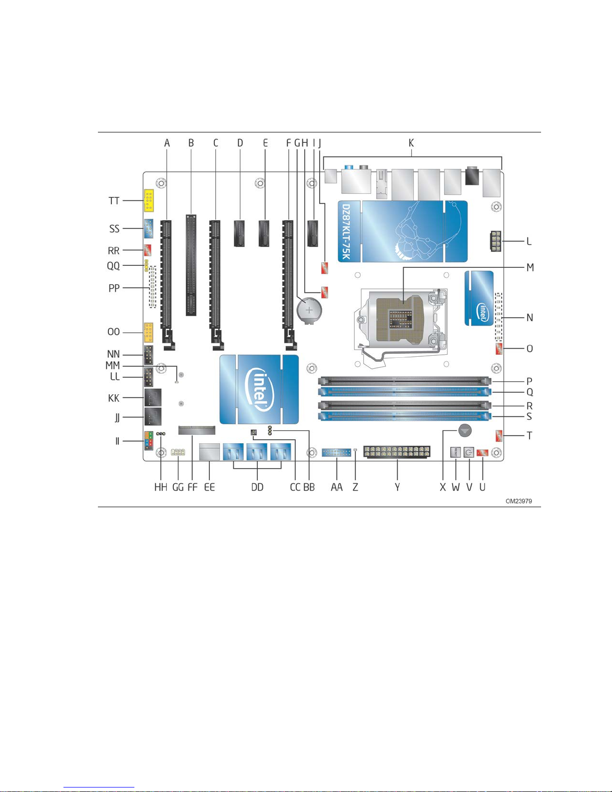
1.1.2 Board Layout
Figure 1 shows the location of the major components on Intel Desktop Board
DZ87KLT-75K.
Product Description
Table 2 lists the components identified in Figure 1.
Figure 1. Major Board Components
13
Page 14

Intel Desktop Board DZ87KLT-75K Technical Product Specification
Table 2. Components Shown in Figure 1
Label Description
A PCI Express x16 add-in card connector (x4 elec tr ic a l; x 16 compatible)
B Conventional PCI add-in card conne c to r
C PCI Express x16 add-in card connec to r (x8 electrical; x16 compatible)
D PCI Express x1 add-in card c onnector
E PCI Express x1 add-in card connector
F PCI Express x16 add-in car d c onnector
G Battery
H Rear chassis fan header 2
I PCI Express x1 add-in car d connector
J Rear chassis fan header 1
K Back panel connectors
L 12 V pro cessor cor e v oltage connector (2 x 4 pin)
M LGA 1150 processor socket
N Volta g e regulator status LEDs
O Processor fan header
P DIMM 3 (Channel A DIMM 0)
Q DIMM 1 (Channel A D IMM 1)
R DIMM 4 (Channel B DIMM 0)
S DIMM 2 (Channel B DIMM 1)
T Front chassis fa n hea d e r 1
U F ront chassis fan heade r 2
V Onboard power button
W Onboard rese t button
X Piezoelectric speaker
Y Main power connec tor (2 x 12)
Z Standby power LED
AA Front panel USB 3 .0 connector
BB BIOS security jumper
CC Chassis intrusion header
DD SATA 6.0 Gb/s connectors through the PC H (b lue )
EE SATA 6.0 Gb/s co nne c tors through a Marvel 88SE9172 controller (gray)
FF PCI Express Full-/Half-Mini Card slot
GG Consumer IR receiver (input) head e r
HH Alternate front panel po w e r/sleep LED header
II Front panel connector
JJ Power On Self Te s t (PO S T) LE D d i s p lay
KK POST LED display
LL Front panel USB 2.0 connector (black)
continued
14
Page 15

Table 2. Components Shown in Figure 1 (continued)
Label Description
MM Power Superv is or LED
NN Fr ont panel USB 2.0 conne c tor (black)
OO Front panel USB 2.0 co nne c tor (orange high cur r e nt c ha r ging)
PP Board status LEDs
QQ S/PDIF header
RR Auxiliary fan header
SS IEEE 1394a front panel connector
TT Front pane l aud io connector
Product Description
15
Page 16
Intel Desktop Board DZ87KLT-75K Technical Product Specification
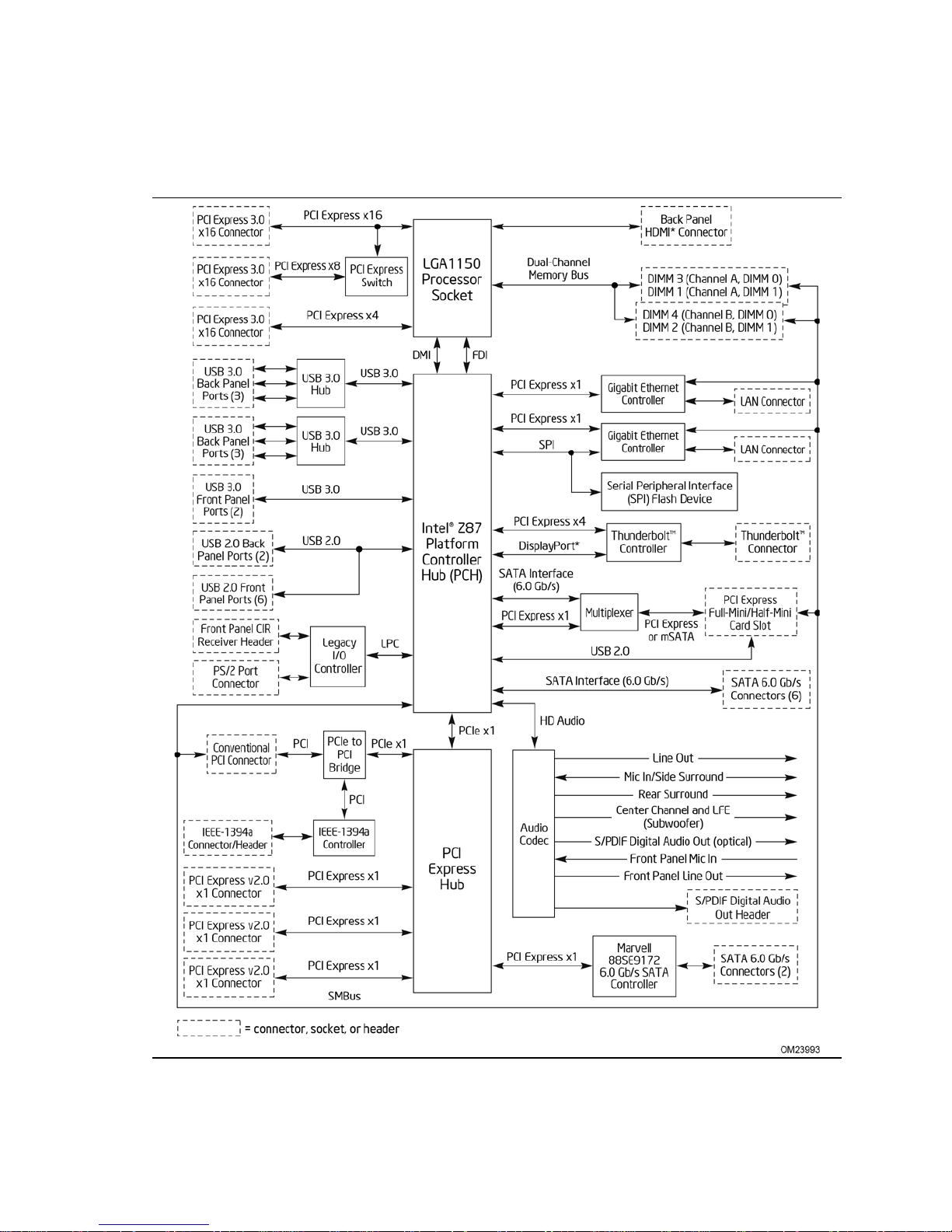
1.1.3 Block Diagram
Figure 2 is a block diagram of the major functional areas of the board.
16
Figure 2. Block Diagram
Page 17
1.2 Online Support
To find information about… Visit this World Wide Web site:
Intel Desktop B oard DZ87KLT-75K http://www.intel.com/products/motherboard/index.htm
Desktop Board Support http://www.intel.com/p/en_US/support?iid=hdr+support
Available config ur a tio ns for the Intel
Desktop Board DZ87KLT-75K
Supported processors http://processormatch.intel.com
Chipset informatio n https://www-
BIOS and driver updates http://downloadcenter.intel.com
Tested memory http://www.intel.com/support/motherboards/desktop/sb/CS-
Integration info r m ation http://www.intel.com/support/go/buildit
1.3 Processor
Product Description
http://ark.intel.com
ssl.intel.com/content/www/us/en/chipsets/performancechipsets/chipsets.html
025414.htm
The board support s 4th generation Intel Core processors. Other processors may be
supported in the future. This board supports processors w ith a maximum wattage of
95 W Thermal Design Power (TDP). The processors listed above are only supported
when falling within the wattage requirements of Intel Desktop Board DZ87KLT-75K.
See the Intel web site listed below for the most up-to-date list of supported
processors.
For information about… Refer to:
Supported processors http://processormatch.intel.com
CAUTION
Use only the processors listed on the web site above. Use of unsupported processors
can damage the board, the processor, and the power supply.
NOTE
This board has specific requirements for providing power to the processor. Refer to
Section 2.5.1 on page 66 for information on power supply requirements for this board.
17
Page 18

Intel Desktop Board DZ87KLT-75K Technical Product Specification
1.3.1 Processor Graphics Subsystem
The board supports graphics through either the processor Intel HD Graphics or a PCI
Express x16 add-in graphics card.
The board support s integrated graphics for processors with Intel HD Graphics.
1.3.1.1 Intel® High Definition (Intel® HD) Graphics
The Intel HD graphics controller features the following:
• 3D Features
DirectX* 11.1 support
OpenGL* 4.0 support
• Video
Next Generation Intel
video playback and enhancement features that improve the end user’s viewing
experience
Encode/transcode HD content
Playback of high definition content including Blu-ray* disc
Superior image quality with sharper, more colorful images
Playback of Blu-ray disc S3D content using HDMI (1.4a spec compliant
with 3D)
DirectX* Video Acceleration (DXVA) support for accelerating video processing
Full AVC/VC1/MPEG2 HW Decode
®
Intel
HD Graphics with Advanced H a rdware Video Trans coding (Intel® Quick
Sync Video)
Note: Intel Quick Sync Video is enabled by an appropriate software application.
®
Clear Video Technology HD support is a collection of
1.3.1.2 High Definition Multimedia Interface* (HDMI*)
The High-Definition Multimedia Interface (HDMI) is provided for transmitting
uncompressed digital audio and video signals to telev ision sets, projectors and other
video displays. It can carry high quality multi-channel audio data and all standard and
high-definition consumer electronics video formats. The HDMI display interface
connecting the processor and display devices utiliz es transition minimized differential
signaling (TMDS) to carry audiovisual information through the same HDMI ca b le. The
processor HDMI interface is designed according to the High-Definition Multimedia
Interface Specification with 3D, 4K, Deep Color, and x.v.Color.
The maximum supported resolution is 4096 x 2304 @ 24Hz or 2560 x 1600 @ 60Hz.
The HDMI interface supports the HDMI 1.4a specification.
Depending on the type of a d d-in card installed in the PCI Express x16 connector, the
HDMI port will behave as described in Table 3.
18
Page 19
Product Description
PCI Express x16 add -in card installed
Enabled
(Note)
Table 3. HDMI Port Status Conditions
PCI Express x16 Connector Status HDMI Port Status
No add-in card installed Enabled
Note: May require B IOS setup menu change s .
1.3.1.3 High-bandwidth Digital Content Protection (HDCP)
HDCP is the technology for protecting high definition content against unauthorized
copy or intercep tion between a source (computer, digital set top boxes, etc.) and the
sink (panels, monitor, and TVs). The PCH supports HDCP 1.4 for content protection
over wired displays (HDM I).
1.3.1.4 Integrated Audio Provided by the HDMI Interface
The HDMI interface from the PCH supports audio. The processor supports two High
Definition audio streams on two digital ports simultaneous ly.
Table 4 shows the specific audio technologies supported by the PCH.
Table 4. Audio Formats Supported by the HDMI Interface
Audio Formats HDMI
AC-3 - Dolby* Digital Yes
Dolby Digital Plus Yes
DTS-HD* Yes
LPCM, 192 kHz/24 bit, 8 Channel Yes
Dolby TrueHD, DTS-HD Master
Audio* (Lossless Blu-ray Disc
Audio Format)
Yes
1.3.1.5 Multiple Display Configurations
The f ollowing multiple display configuration modes are supported (with appropr iate
driver software):
• Single Display is a mode with one display port activated to display the output to
one display device.
• Intel
• Extended Desktop is a mode with up to three display po rts activated to drive the
®
Display Clone is a mode with up to three display ports activated to drive the
display content of same color depth setting but potentially different r efresh rate
and resolution settings to all the active display devices connected.
content with potentially different color depth, refresh rate, and resolution settings
on each of the active display devices connected.
19
Page 20

Intel Desktop Board DZ87KLT-75K Technical Product Specification
1.3.1.6 PCI Express Graphics
4th generation Intel Core processors support PCI Express 3.0, 2.x, and 1.x:
• PCI Express 3.0 with a raw bit rate of 8.0 GT/s results in an effective bandwidth of
1 GB/s each direction per lane. The maximum theoretical bandwidth of the x16
interface is 16 GB/s in each direction, simultaneously, for a total bandwidth of
32 GB/s.
• PCI Express 2.x with a raw bit rate of 5.0 GT/s results in an effective bandwidth of
500 MB/s each direction per lane. The maximum theoretical bandwidth of the x16
interface is 8 GB/s in each direc tion, simultaneously, for a total bandwidth of
16 GB/s.
• PCI Express 1.x with a raw bit rate of 2.5 GT/s results in an effective bandwidth of
250 MB/s each direction per lane. The maximum theoretical bandwidth of the x16
interface is 4 GB/s in each direc tion, simultaneously, for a total bandwidth of
8 GB/s.
For information about Refer to
PCI Express te c hnology http://www.pcisig.com
20
Page 21

Product Description
1.4 Intel® Z87 Express Chipset
Intel Z87 Express Chipset with Direct Media Interface (DMI) interconnect provides
interfaces to the processor and USB, SATA, LPC, LAN, and PCI Express. The Intel Z87
Express Chipset is a centralized controller for the board’s I/O paths.
For information about Refer to
The Intel Z87 chipset
Resources used by the chipset Chapter 2
http://www.intel.com/products/desktop/chipsets/index.htm
1.4.1 Direct Media Interface (DMI)
Direct Media Interface (DMI) is the chip-to-chip connection between the processor and
the PCH. This high-speed interface integrates advanced priority-based servicing
allowing for concurrent traffic and true isochronous transfer capabilities.
1.5 System Memory
The board has four DIMM sockets and supports the following memory features:
• 1.5 V DDR3 SDRAM DIMMs with gold plated contacts, with the option to raise the
voltage to support higher performance DD R3 S DRAM DIMMs.
• 1.35 V Low Voltage DDR3 DIMMs (JEDEC specification)
• Unbuffered, single-sided or double-sided DIMMs with the following restriction:
Double-sided DIMMs with x16 organization are not suppor ted.
• 32 GB maximum total system memory (using 4 Gb memory technology). Refer to
Section 2.1.1 on page 49 for information on the total amount of addressable
memory.
• Minimum total system memory: 1 GB using 512 MB x16 module
• Non-ECC DIMMs
• Serial Presence Detect
• Support for DDR3 1066 MHz up to 2400+ M Hz DIMMs
DDR3 2133 dual channel mode is s upported via the Overclocking Assistant
DDR3 2400 dual channel mode is s upported via XMP profiles and manual mode
DDR3 2667 single channel mode is supported via XMP profiles and manual
mode
• XMP version 1.3 performance profile support for memory speeds above 1600 MHz
NOTE
To be fully compliant with all applicable DDR SDRAM memory specifications , the board
should be populated with DIMMs that support the Seri a l Presence Detect (SPD) data
structure. This allows the BIOS to read the SPD data and program the chipset to
accurately configure memory settings for optimum performance. If non-SPD memory
is installed, the BIOS will attempt to correctly configure the memory settings, but
performance and reliability may be impacted or the DIMMs may not functi on under the
determined frequency.
21
Page 22
Intel Desktop Board DZ87KLT-75K Technical Product Specification
CAUTION
1.5 V is the recommended and default setting for DDR3 memory voltage. The other
memory voltage settings in the BIOS Setup program are provided for performance
tuning purposes only. Altering the memory voltage may (i) reduce system stability
and the useful life of the system, memory, and processor; (ii) cause the processor and
other system components to fail; (iii) cause reductions in system performance; (iv)
cause additional heat or other damage; and (v ) affect system da ta integrity.
Intel has not tested and does not warranty the operation of the processor beyond its
specifications. For information on the processor warranty, refer to
http://www.intel.com/support/processors/sb/CS-
020033.htm?wapkw=(processor+warranty).
Intel assumes no responsibility that the memory installed on the deskto p board, if used
with altered clock frequencies and/or voltages, will be fit for any particular purpose.
Check with the memory manufacturer for warranty terms and additional details.
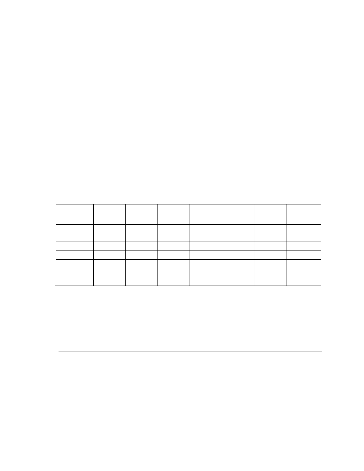
Table 5 lists the supported DIMM configurations.
Table 5. Supported Memory Configurations
DIMM
Capacity Configuration
1024 MB SS 1 Gbit 128 M x8/empty 8
1024 MB SS 2 Gbit 128 M x16/empty 4
2048 MB DS 1 Gbit 128 M x8/128 M x8 16
2048 MB SS 2 Gbit 128 M x16/empty 8
4096 MB DS 2 Gbit 256 M x8/256 M x8 16
4096 MB SS 4 Gbit 512 M x8/empty 8
8192 MB DS 4 Gbit 512 M x8/512 M x8 16
Note: “DS” ref er s to d ouble-sided memor y modules (containing two rows of SDRAM) and “SS” refers to
single-sided memor y modules (containing o ne r ow of SDRAM).
(Note)
For information about… Refer to:
Tested Memory http://support.intel.com/support/motherboards/desktop/sb/CS-
XMP Tested Memory http://www.intel.com/personal/gaming/extremememory.htm
SDRAM
Density
025414.htm
SDRAM Organization
Front-side/Back-side
Number of SDRAM
Devices
22
Page 23

Product Description
1.5.1 Memory Configurations
4th generation Intel Core processors support the following types of memory
organization:
• Dual channel (Interleaved) mode. This mode offers the highest throughput for
real world applications. Dual c hannel mode is enabled when the installed memory
capacities of both DIMM channels are equal. Technology and device width can vary
from one channel to the other but the installed memory capacity for each channel
must be equal. If different speed DIMMs are used between channels, the slowest
memory timin g will be u sed.
• Single channel (Asymmetric) mode. This mode is equivalent to single channel
bandwidth operation for real world applications. This mode is used when o nly a
single DIMM is installed or the memory capacities are unequal. Technology and
device width can vary from one channel to the other. If different speed DIMMs are
used between channels, the slowest memory timing will be used.
For information about… Refer to:
Memory Config uration Examples http://www.intel.com/support/motherboards/desktop/sb/cs-
011965.htm
23
Page 24
Intel Desktop Board DZ87KLT-75K Technical Product Specification
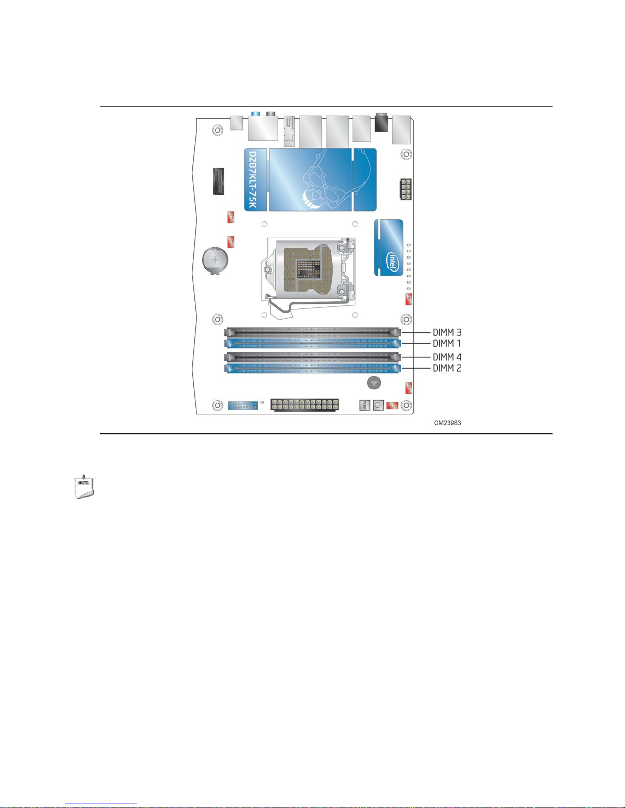
Figure 3 illustrates the DIMM configuration.
Figure 3. DIMM Configuration
NOTE
For best memory performance always install memory in the blue DIMM sockets if
installing only two DIMMs on your board.
24
Page 25

Product Description
1.5.2 USB
The PCH contains up to two Enhanced Host Controller Interface (EHCI) host controllers
that support USB high-speed signaling. High-speed USB 2.0 a llows da ta transfers up to
480 Mb/s. All ports are high-speed, full-speed, and low-speed capable.
The PCH also contains an integrated eXtensible Host Controller Interface (xHCI) host
controller which supports USB 3 .0 ports. This contr oller allows data transfers up to
5 Gb/s. The controller supports SuperSpeed (SS), high-speed (HS), full-speed (FS),
and low-speed (LS) traffic on the bus.
The Intel Z87 Express Chipset provides the USB controller for the USB 2.0/3.0 ports.
The port arrangement is as follows:
• USB 3.0 ports:
Six ports implemented with stacked back panel connectors (blue)
Two ports implemented through one dual-port internal connectors (blue)
• USB 2.0 ports:
Two ports implemented with stac ked back panel connec tors (orange high
current charging ports)
Six front panel por t s are implemented through three dual-port internal
connectors (two black and one orange high current charging po rt)
NOTE
Computer systems that have an unshielded cable atta ched to a USB port may not meet
FCC Class B requirements, even if no device is attached to the cable. Use a shielded
cable that meets the requirements for full-speed devices.
For information about Refer to
The location of the USB c onnectors on the back panel Figure 12, page 51
The location of the front panel USB headers Figure 13, page 52
25
Page 26

Intel Desktop Board DZ87KLT-75K Technical Product Specification
1.5.3 SATA Interfaces
The board provides eight SATA connectors, through the PCH, which support one device
each:
• Six SATA 6.0 Gb/s interfaces through the Intel Z87 Express Chipset with Intel
Rapid Storage Technology RAID support (blue)
• Two SATA 6.0 Gb/s interface s through a Marvel 88SE9172 controller (gray)
The PCH provides independent SATA ports with a theoretical maximum transfer rate of
6.0 Gb/s. A point-to-point interface is used for host to device connections.
The PCH supports the Serial ATA Specification, Revision 3.0. The PCH also supports
several optional sections of the Serial ATA II: Extensions to Serial ATA 1.0
Specification, Revision 1.0 (AHCI support is required for some elements).
NOTE
Many SATA drives use new low-voltage power connectors and require adapters or
power supplies equipped with low-voltage power connectors.
®
For more information, see: http://www.serialata.org/
For information about Refer to
The location of the SA TA c onnectors Figure 13, page 52
.
1.5.3.1 Intel® Rapid Storage Technology/SATA RAID
The PCH supports Intel® Rapid Storage Technology, providing both AHCI and
integrated RAID functionality. The RAID capability provides high-performance RAID 0,
1, 5, and 10 functio nality on all SATA ports. Other RAID features include hot spare
support, SMART alerting, and RAID 0 auto replace. Software components include an
Option ROM for pre-boot configuration and boot functionality, a Microsoft* Windows*
compatible driver, and a user interface for configuration and management of the RAID
capability of the PCH.
1.5.3.2 Intel® Smart Response Technology
Intel® Smart Response Technology is a disk caching solution that can provide improved
computer system performance with improved power savings. It allows configuration of a
computer syste m w ith the a dvantage of having HDDs for maximum storage ca pacity
with system performance at or near SSD performance levels.
For more information on Intel Smart Response Technology, go to
http://www.intel.com/support/chipsets/sb/CS-032826.htm
NOTE
In order to use supported RAID and Intel Smart Response Technology features, you
must first enable RAID in the BIOS.
26
Page 27

Product Description
1.6 Real-Time Clock Subsystem
A coin-cell battery (CR2032) powers the real-time clock and CMOS memory. When the
computer is not plugged into a wall socket, the battery has an estimated life of three
years. When the computer is plugged in, the standby current from the power supply
extends the life of the battery. The clock is accurate to ± 13 minutes/year at 25 ºC
with 3.3 VSB applied via the power supply 5V STBY rail.
NOTE
If the battery and AC po w er fail date and time values will be reset and the user will be
notified during POST.
When the voltage drops below a certain level, the BIOS Setup progr am settings stored
in CMOS RAM (for example, the date and time) might not be accurate. Replace the
battery with an equivalent one. Figure 1 on page 13 shows the location of the battery.
1.7 Super I/O Controller
The I/O controller provides the following features:
• Consumer Infrared (CIR) header
• PS/2-style keyboard/mouse interface on the back panel
• Serial IRQ interface c ompatible with serialized IRQ support for PCI systems
• Intelligent power management, including a programmable wake-up event interface
• PCI power management support
The BIOS Setup program provides configuration options for the I/O controller.
27
Page 28
Intel Desktop Board DZ87KLT-75K Technical Product Specification
Line-Out
Mic-In
1.8 Audio Subsystem
The board support s Intel HD Audio through the Realtek ALC898 audio codec as well as
the HDMI interface. The audio subsystem supports the following features:
• Advanced jack sense for the back panel audio jacks that enables the audio codec to
recognize the device tha t is connected to an audio por t.
• Digital-to-Analog Converters (DAC) with 110 dB SNR (A-weighting) and Analog-toDigital Converters (ADC) with 104 dB SNR (A-weighting).
• Ten DAC channels support 16/20/24-bit PCM format for 7.1 channel sound
playback, plus two channels of concurre nt inde pendent stereo sound output
(multiple streaming) through the front panel output.
• Three stereo ADCs support 16/20-bit PCM format, multiple stereo recording
• Microphone Acoustic Echo Cancellation (AEC), Noise Suppr ession (NS), and Beam
Forming (BF) technology for voice applications.
• Windows 7 Ultimate c ertification.
Table 6 lists the supported functions of the front panel and back panel audio jacks.
Table 6. Audio Jack Support
Audio Jack
FP Green Default
FP Pink Default
Rear Blue Ctrl panel Ctrl panel Default Ctrl panel Ctrl panel Ctrl panel
Rear Green Ctrl panel Default Ctrl panel Ctrl panel Ctrl panel C trl panel
Rear Pink Ctrl panel Ctrl panel Ctrl panel Ctrl panel Ctrl panel Ctrl panel Default
Rear Black Ctrl panel Ctrl panel Ctr l p ane l Default Ctrl panel Ctrl panel
Rear Orange Ctrl panel Ctrl panel Ctrl panel Ctrl panel Default Ctrl panel
Microphone
Head-
phones
(Front
Speaker)
Line-In
Rear
Surround
Center/
Sub
1.8.1 Audio Subsystem Software
Audio software and drivers are available from Intel’s World Wide Web site.
For information about Refer to
Obtaining audio sof tw a r e and drivers Section 1.2, page 17
(Side
Surround)
28
Page 29
Product Description
1.8.2 Audio Subsystem Components
The audio subsystem includes the following components:
• Intel Z87 Express Chipset
• Realtek ALC898 audio codec
• Front panel audio header that supports Intel HD audio and AC ’97 audio (a 2 x 5-
pin header that provides mic in and line out signals for front panel audio
connectors) (yellow)
• S/PDIF digital audio out header (1 x 4-pin header) (yellow)
• S/PDIF digital audio out connector on the back panel
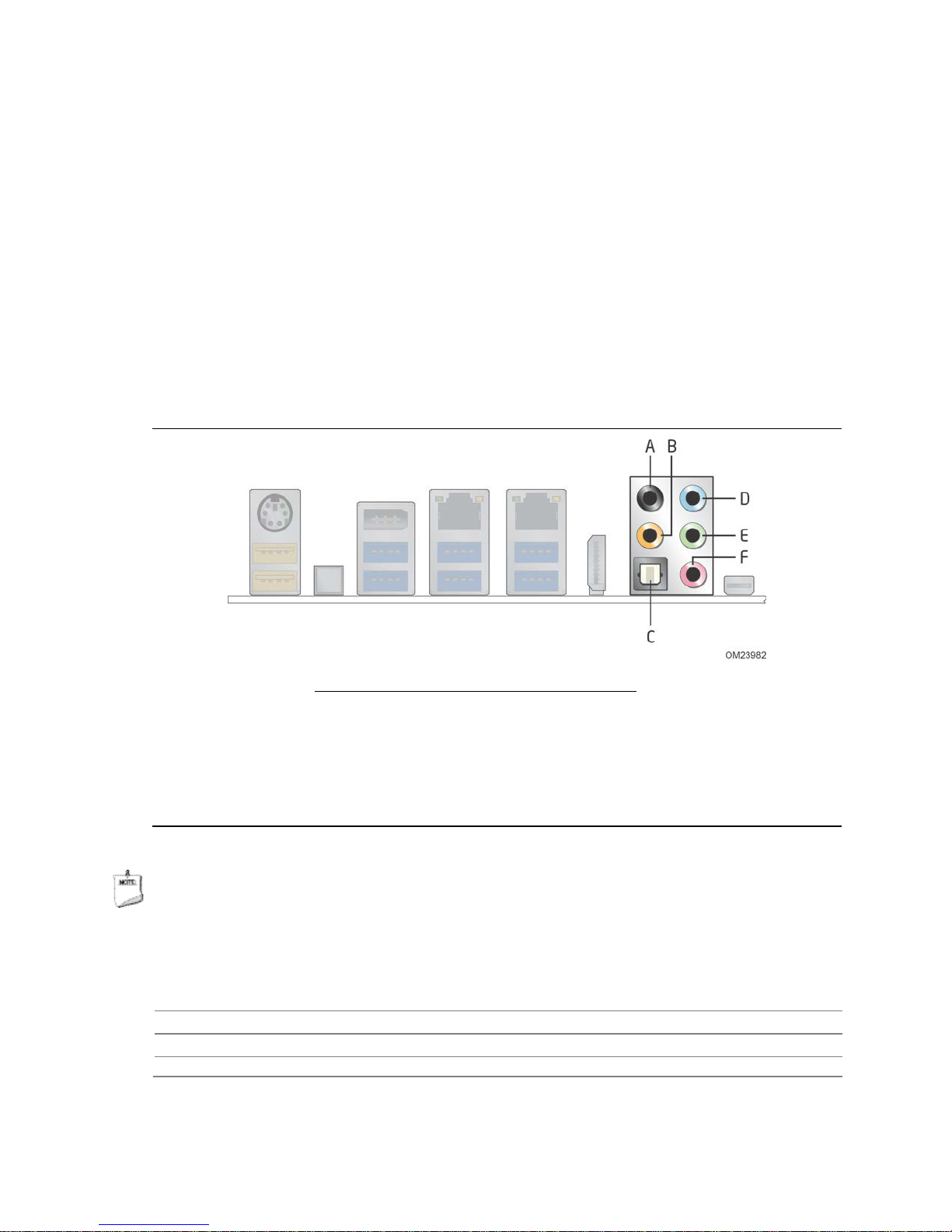
• 5-port analog audio input/output stack on the back panel
The back panel audio connectors are configurable through the audio device drivers.
The available configur able back panel audio c onnectors are shown in Figure 4.
Item Description
A Rear surround
B Cente r c ha nne l and LFE (Subwoofer )
C S/PDI F out (optical)
D Line-in
E Line-out (front speaker)
F Mic-in (side surround)
Figure 4. Back Panel Audio Connectors
NOTE
The back panel audio line out connector is designed to power headphones or amplified
speakers only. Poor audio quality occurs if passive (non-amplified) speakers are
connected to this output.
For information about Refer to
The locations of the f ront panel audio header and S/PDIF audio header Figure 13, page 52
The signal names of the f ront panel audio header and S/PDIF audio header Section 2.2.2.1, page 54
The back panel audio c onnectors Section 2.2.1, page 51
29
Page 30

Intel Desktop Board DZ87KLT-75K Technical Product Specification
1.9 Connectivity
1.9.1 LAN Subsystem
The two LAN subsystems consist of the following:
• Intel i217V Gigabit Ethernet Controller and Intel i210 Gigabit Ethernet Controller
(10/100/1000 Mb/s)
• Intel Z87 Express Chipset
• RJ-45 LAN connector w ith integrated status LEDs
Additional features of the LAN subsystem include:
• CSMA/CD protocol engine
• LAN connect interface between the PCH and the LAN controller
• Conventional PCI bus power management
ACPI tec hnology support
LAN wake capabilities
• LAN subsystem software
For information about Refer to
LAN software and d rivers http://downloadcenter.intel.com
1.9.1.1 Intel® i217V Gigabit Ethernet Controller and Intel® i210
Gigabit Ethernet Controller
The Ethernet Controllers support the following features:
Network Features:
• Compliant with the 1 Gb/s Ethernet 802.3, 802.3u, 802.3z, 8 02.3ab specifications
• Multi-speed operation: 10/100/1000 Mb/s
• Full-duplex operation at 10/100/1000 Mb/s; Half-duplex operation at 10/100 Mb/s
• Flow control support compliant with the 802.3X specification as w ell as the specific
operation of asymmetrical flow control defined by 802.3z
• VLAN support compliant with the 802.3q specification
• MAC address filters: perfect match unicast filters, multicast hash filtering,
broadcast filter, and promiscuous mode
Performance Features:
• Configurable receive and transmit data FIFO, programmable in 1 KB increments
• TCP segmentation capability compatible with Windows NT 5. x off-loading features
• Fragmented UDP checksum offload for packet reassembly
• IPv4 and IPv6 c hecksum offload suppo rt (receive, tr a nsmit, and TCP segmentation
offload)
• Split header support to eliminate payload copy from user space to host spac e
• Receive Side Scaling (RSS) with two hardware receive queues
• Supports 9018 bytes of jumbo packets
• Packet buffer size
30
Page 31

Product Description
• LinkSec of fload compliant with 802.3ae specification
• TimeSync offload compliant with 802.1as specification
Power Management Features:
• Magic Packet* wake-up enable with unique MAC address
• ACPI register set and power down functionality supporting D0 and D3 states
• Full wake up support (APM, ACPI)
• MAC power down at Sx, DMoff with and without WoL
• Auto connect battery saver at S0 no link and Sx no link
• Energy Efficient Ethernet (EEE) support
• Latency Tolerance Reporting (LTR)
• Optimized Buffer Flash/Fill (OBFF) support
• ARP and ND proxy support through LAN Connec ted Device proxy
• Wake on LAN (WoL) from Deep Sx
• Provides lower power usage to meet ENERGY STAR 5.2 and ErP specifications
1.9.1.2 LAN Subsystem Software
LAN software and drivers are available from Intel’s World Wide Web site.
For information about Refer to
Obtaining LAN softw are and drivers http://downloadcenter.intel.com
31
Page 32

Intel Desktop Board DZ87KLT-75K Technical Product Specification
1.9.1.3 RJ-45 LAN Connectors with Integrated LEDs
Two LEDs are built into the RJ-45 LAN connectors (shown in Figure 5).
Item Description
A Link LED (green)
B Data Rate LED (green/yellow)
C Link LED (green)
D D ata R a te LED (green/yellow)
Figure 5. LAN Connectors LED Locations
Table 7 describes the LED states w hen the board is power ed up and the LAN
subsystems are operating.
Table 7. LAN Connector LED States
LED LED Color LED State Condition
Off LAN link is not establishe d .
Link Green
Data Rate Green/Yellow
On LA N link is e s tablished.
Blinking LAN activity is occurring.
Off 10 Mb/s data rate is selected.
Green 100 Mb/s data rate is selected.
Yellow 1000 Mb/s data rate is selected.
32
Page 33

Product Description
1.9.2 Thunderbolt™ Technology Interface
The board’s Thunderbolt Technology Interface is supported by an Intel® L3310L CIO
10 Gb Controller.
The Thunderbolt controller connects a PC and other dev ices, transmitting and receiving
information for PCI Express and DisplayPort protocols. The Thunderbolt controller
switches between the two protocols to support communications over a single cable.
Thunderbolt technology is implemented o n Intel Desktop Board DZ87KLT-75K as a
plug and play interface. No software drivers are required.
1.10 Bluetooth*/WiFi Module
The Bluetooth*/WiFi module is suppleme nta l har dware that is included with certain
Desktop Boards (see Figure 6).
Figure 6. Bluetooth/WiFi Module
1.10.1 Bluetooth Technology (Module)
The Bluetooth Module enables the user to connect with a variety of Bluetooth enabled
devices. Driver support is provided by Microsoft operating systems like Microsoft Vista
and Microsoft Windows 7. The Bluetooth driver stack is supplied by Microsoft but some
Bluetooth enable devices might provide additional Bluetooth features and for proper
functioning of those features, will need their own sup plied driver s installed.
• CSR Bluetooth module (BC0401PC08)
• Maximum data rate 3.0 Mb/s
• Forward and backward compatibility with Bluetooth v1.1, v1.2, v2.0, and v2.1
• Integrated antenna
• Operating system support (Windows XP, Windows Vista, and Windows 7 both 32 bit
and 64 bit)
For information about Refer to
Obtaining Bluetooth information and drive r s http://msdn.microsoft.com/en-
us/library/aa362932(VS.85).aspx
33
Page 34

Intel Desktop Board DZ87KLT-75K Technical Product Specification
1.10.2 WiFi 802.11 Wireless (Module)
The WiFi Module enables the user to connect with a variety of WiFi enabled networks,
access points and allows peer to peer connections. Driver support is provided by
Microsoft operating systems like Microsoft Vista and Microsoft Windows 7 with
additional support provided by the supplied WiFi driver included on the Driver DVD and
online.
• Ralink WiFi 802.11 (RT8070)
• Range up to 300 meters
• Supports the following:
IEEE 80 2.11B supports up to 11 Mb/s data rate
IEEE 80 2.11G supports up to 54 Mb/s data rate
IEEE 80 2.11N supports up to 150 Mb/s data rate
• Integrated antenna
• Operating system support (Windows XP, Windows Vista, and Windows 7 both 32 bit
and 64 bit)
For information about Refer to
Obtaining WiFi infor ma tio n and drivers http://msdn.microsoft.com/en-
us/library/aa362932(VS.85).aspx
34
Page 35

Product Description
1.11 Hardware Management Subsystem
The hardware management features enable the board to be compatible with the Wired
for Management (WfM) specification. The board has several hardware management
features, including the following:
• Fan monitoring and control
• Thermal and voltage monitoring
• Chassis intrusion detection
1.11.1 Hardware Monitoring and Fan Control
The hardware monitoring and fan control subsystem is based on the Nuvoton device,
which supports the following:
• Processor and system ambient temperature monitoring
• Chassis fan speed monitoring
• Power monitoring of +12 V, +5 V, +3.3 V, V
• SMBus interface
SM
, +V
, and PCH VCC
CCP
1.11.2 Fan Monitoring
Fan monitoring can be implemented using Intel® Desktop Control Center or third-party
software.
For information about Refer to
The functions of the f an he aders Section 1.12.2.2, page 41
1.11.3 Chassis Intrusion and Detection
The board supports a chassis security feature that detects if the chassis cover is
removed. The security feature uses a mechanical switch on the chassis that attaches
to the chassis intrusion header. When the chassis cover is removed, the mechanical
switch is in the closed position.
For information about Refer to
The location of the chas s is intrusion header Figure 13, page 52
35
Page 36

Intel Desktop Board DZ87KLT-75K Technical Product Specification
1.11.4 Thermal Monitoring
Figure 7 shows the locations of the thermal sensors and fan headers.
36
Item Description
A R ear chassis fan header 1
B Rear chassis fan header 2
C Ther mal d iode, located on pr ocessor die
D Processor fan header
E Front fan heade r 1
F Front fan header 2
G Thermal diode, located on the Intel Z87 Exp ress
Chipset
H Auxiliary fan header
Figure 7. Thermal Sensors and Fan Headers
Page 37

Product Description
1.12 Power Management
Power management is implemented at several levels, including:
• Software support through Advanced Configuration and P ower Interface (ACPI)
• Hardware support
1.12.1 ACPI
ACPI gives the operating system direct control over the power management and Plug
and Play functions of a computer. The use of ACPI with this board requires an
operating system that provides full ACPI support. ACPI features include:
• Plug and Play (including bus and device enumeration)
• Power management control of individual devices, add-in boards (some add-in
boards may require an ACPI-aware driver), video displays, and hard disk drives
• Methods for achieving less than 15-watt system operation in the power-on/standby
sleeping state
• A Soft-off feature that enables the oper a t ing sy stem to power-off the computer
• Support for multiple wake-up events (see Table 10 on page 39)
• Support for a front panel power and sleep mode switch
Table 8 lists the system states based on how long the power switch is pressed,
depending on how ACPI is configured with an ACPI-aware operating system.
Table 8. Effects of Pressing the Power Switch
If the system is in this
state…
Off
(ACPI G2/G5 – Soft off)
On
(ACPI G0 – wo rking state)
On
(ACPI G0 – wo rking state)
Sleep
(ACPI G1 – slee ping state)
Sleep
(ACPI G1 – slee ping state)
…and the power switch is
pressed for
Less than four seconds Power-on
Less than four seconds Soft-off/Standby
More than six second s Fail safe power-off
Less than four seconds Wake-up
More than six second s Power-off
…the system enters this state
(ACPI G0 – wo rking state)
(ACPI G1 – slee ping state)
(ACPI G2/G5 – Soft off)
(ACPI G0 – wo rking state)
(ACPI G2/G5 – Soft off)
1.12.1.1 System States and Power States
Under ACPI, the operating system directs all system and device power state
transitions. The opera ting sy stem puts devices in and out of low-power states based
on user preferences and knowledge of how devices are being used by applications.
Devices that are not being used can be turned off. The operating system uses
information from applications and user settings to put the system as a whole into a
low-power state.
Table 9 lists the power states supported by the board along with the assoc iate d system
power targets. See the ACPI specification for a complete description of the various
system and power states.
37
Page 38

Intel Desktop Board DZ87KLT-75K Technical Product Specification
Table 9. Power States and Targeted System Power
Global States Sleeping States
G0 – working
state
G1 – sleeping
state
G1 – sleeping
state
G2/S5 S5 – Soft off.
G3 –
mechanical off
AC power is
disconnected
from the
computer.
Notes:
1. To tal system power is d e p e ndent on the system configuration, including add-in boards and per ipherals
powered by the system chassis’ power supply.
2. D e p e ndent on the standby po w e r consumption of w ake-up devices used in the system.
S0 – working C0 – working D0 – working
S3 – Suspend to
RAM. Context
saved to RAM.
S4 – Suspend to
disk. Context
saved to disk.
Context not saved .
Cold boot is
required.
No power to the
system.
Processor
States
No power D3 – no power
No power D3 – no power
No power D3 – no power
No power D3 – no power for
Device States
state.
except for
wake-up logic.
except for
wake-up logic.
except for
wake-up logic.
wake-up logic,
except when
provided by
battery or
external source.
Targeted System
Power
Full power > 30 W
Power < 5 W
Power < 5 W
Power < 5 W
No power to the s y s te m .
Service can be performed
safely.
(Note 1)
(Note 2)
(Note 2)
(Note 2)
38
Page 39

Product Description
Note 1)
(Note 1)
(Notes 1 and 3)
(Note 1)
(Note 1)
1.12.1.2 Wake-up Devices and Events
Table 10 lists the devices or specific events that can wake the computer from specific
states.
Table 10. Wake-up Devices and Events
These devices/events can wake up the computer… …from this state
Power switch S3, S4, S5
RTC alarm S3, S4, S5
LAN S3, S4, S5
USB S3
PME# signal S3, S4, S5
WAKE# S3, S4, S5
Consumer IR S3, S4, S5
Notes:
1. S 4 im p lie s operating system s up port only.
2. Wake from S4 and S5 is recommended by Microsoft.
3. Wak e on LAN is only suppo r te d from sleep (S3) or hibernate (S4 ) in Wind ows 8.
4. Whe n D e e p S4/S5 is enabled o nly Wake from RTC and Front Panel is supported.
NOTE
(
(Notes 2 and 4)
The use of these wake-up events from an ACPI state requires an operating system that
provides full ACPI support. In addition, software, drivers, and peripherals must fully
support ACPI wake events.
39
Page 40

Intel Desktop Board DZ87KLT-75K Technical Product Specification
1.12.2 Hardware Support
CAUTION
Ensure that the powe r supply provides adequate +5 V standby current if LAN wake
capabilities and Instantly Avai lable PC technology f eatures are used. Failure to do so
can damage the power supply. The total amount of standby current required depends
on the wake devices supported and manufac turing options.
The board provides several power management hardware features, including:
• Power connector
• Fan headers
• LAN wake capabilities
• Instantly Available PC technology
• Wake from USB
• Power Manageme nt Event signal (PME#) wake-up suppor t
• PCI Express WAKE# signal support
• Wake from Consumer IR
• Wake from S5
• Power Supervisor
• +5 V Standby Power Indicator LED
LAN wake capabilities and Instantly Available PC technology require power from the
+5 V standby line.
NOTE
The use of Wake from USB from an ACPI state requires an operating system that
provides full ACPI support.
1.12.2.1 Power Connector
ATX12V-compliant power supplies can turn off the system power through system
control. When an ACPI-enabled system receives the correct command, the power
supply removes all non-standby voltages.
When resuming from an AC power failure, the computer returns to the power state it
was in before power was interrupted (on or off). The computer’s response can be set
using the Last Power State feature in the BIOS Setup program’s Boot menu.
For information about Refer to
The location of the main p o w e r connector Figure 13, page 52
The signal names of the main p ower connector Table 26, page 59
40
Page 41

Product Description
1.12.2.2 Fan Headers
The function/operation of the fan headers is as follows:
• The fans are on when the board is in the S0 state
• The fans are off when the board is off or in the S3, S4, or S5 state
• Each fan header is wired to a fan tachometer input of the hardware monitoring and
fan control ASIC
• All fan headers support closed-loop fan control that can adjust the fan speed or
switch the fan on or off as needed
• All fan headers have a +12 V DC connection
• 4-pin fan headers are controlled by Pulse Width Modulation
For information about Refer to
The location of the fan he a d e rs Figure 13, page 52
The location of the fan he a d e rs and sensors for thermal monitoring Figure 7, page 36
1.12.2.3 LAN Wake Capabilities
CAUTION
For LAN wake capabi li ties, the +5 V standby line for the power supply must be capable
of providing adequate +5 V standby current. Fail ure to provide ad equate standby
current when implementing LAN wake capabilities can damage the power supply.
LAN wake capabilities enable remote wake-up of the computer through a network. The
LAN subsystem PCI bus network adapter monitors networ k traffic at the Media
Independent Inte rface. Upon detecting a Magic Packet* frame, the LAN subsystem
asserts a wake-up signal that powers up the computer. D epending on the LAN
implementation, the board supports LAN wake capabilities with ACPI in the following
ways:
• The PCI Express WAKE# signal
• The PCI bus PME# signal for PCI 2.3 co mp liant LAN designs
By Ping
Magic Packet
• The onboard LAN s ubsystem
41
Page 42

Intel Desktop Board DZ87KLT-75K Technical Product Specification
1.12.2.4 Instantly Available PC Technology
CAUTION
For Instantly Available PC technology, the +5 V standby line for the power supply must
be capable of providing adequate +5 V standby current. Failure to provide adequate
standby current when implementing Instantly Available PC technology can damage the
power supply.
Instantly Available PC technology enables the board to enter the ACPI S3 (Suspend-toRAM) sleep-state. While in the S3 sleep-state, the computer will appear to be off (the
power supply is off, a nd the front panel LED is ambe r if dual colored, or off if single
colored.) When signaled by a w ake-up device or event, the system quickly returns to
its last known wake state. Table 10 on page 39 lists the devices and events that can
wake the computer from the S3 state.
The board support s the PCI Bus Power Management Interface Specification. Add-in
boards that also suppor t this s pecification can participate in power managem ent and
can be used to wake the computer.
The use of Instantly Available PC technology requires operating system support and
PCI 2.2 compliant add-in cards, PCI Express add-in cards, and drivers.
1.12.2.5 Wake from USB
USB bus activity wakes the computer from an ACPI S3 state.
NOTE
Wake from USB requires the use of a USB peripheral that supports Wake from USB and
is supported by the operating system.
1.12.2.6 PME# Signal Wake-up Support
When the PME# signal on the Conventional PCI bus is asserted, the computer wakes
from an ACPI S3, S4, o r S5 state (with Wake on PME enabled in the BIOS).
1.12.2.7 WAKE# Signal Wake-up Support
When the WAKE# signal on the PCI Express bus is asserted, the computer wakes from
an ACPI S3, S4, or S5 state.
1.12.2.8 Wake from Consumer IR
CIR activity wakes the computer from an ACPI S3, S4, or S5 state.
1.12.2.9 Wake from S5
When the RTC Date and Time is set in the BIOS, the computer will automatically wake
from an ACPI S5 state.
42
Page 43

Product Description
1.12.2.10 Power Supervisor
The Power Supervisor actively monitors the input voltages from the power supply and
protects the board and any attached peripherals from electrical overstress and possible
physical damage. The Power Supervisor will activate if it detects the power supply
voltage rails have deviated outside the current ATX po wer supply specification and safe
operating levels.
If the Power Supervisor detects an out of spec voltage, the f ollowing will happen:
1. The board will be powered down immediately to protect circuits from electrical
overstress and possible physical damage.
2. A red warning LED (see Figure 1) on the board will activate as a visual cue.
3. During the next power on, a message will be displayed on the screen to notify the
user that the power supply voltage rails have deviated outside the current ATX
power supply specification and sa fe operating levels.
4. A message will be added to the BIOS Event Log fo r each event that takes place
until the BIOS Event Log is cleared.
1.12.2.11 +5 V Standby Power Indicator LED
The +5 V standby power indicator LED shows that power is still present even when the
computer appears to be off. Figure 10 shows the location of the standby power LED.
CAUTION
If AC power has been switched off and the standby power indica tor is still lit,
disconnect the power cord before installing or removing any devices connected to the
board. Failure to do so could damage the board and any attached de vices.
43
Page 44

Intel Desktop Board DZ87KLT-75K Technical Product Specification
Figure 8. Location of the Standby Power LED
44
Page 45

Product Description
1.12.2.12 Voltage Regulator (VR) Status LEDs
The VR status LEDs provide a real-time indication of how many processor VR phases
are active. During normal system operation the power requirements of the processor
can vary due to its power saving features. When the processor is in a low-power or
idle state it requires less power to be provided by the VR. The VR res p onds to the
lower power demand by shutting down unneeded phases thereby increasing overall
power efficiency. Each VR phase has an L ED connected to it that indicates w hen that
phase is active. Figure 9 shows the location of the VR status LEDs.
Item Description
A VR S tatus LEDs
Figure 9. Location of the VR Status LEDs
45
Page 46

Intel Desktop Board DZ87KLT-75K Technical Product Specification
1.13 Board Status LEDs
The Desktop Board provides 11 LEDs that allow you to monitor the board’s pro g ress
through the BIOS Power-on Self-Test. At initial pow er on, all the LEDs are off. When
the BIOS starts an activity such as memory initialization, the corre sponding LED starts
flashing. Once the activity has completed, the LED will remain on. Figure 10 shows
the location of the board status LEDs.
Figure 10. Location of Board Status LEDs
46
Page 47

Product Description
Table 11 gives a description of the LEDs shown in Figure 10.
Table 11. Board Status LEDs
Item/Callout
in Figure 10 LED Name
A Hard Drive Activity Blue On/Off Hard drive
B CPU Hot Red On/Off Discrete circuit
C VR Hot Red On/Off Discrete circuit
D Watch Dog Fire / Bac k to
BIOS
E CPU Ini tializ ation Green On/Off/Flash BIOS
F Memory Initializatio n Green On/Off/Flash BIOS
G Video Initialization Green On/Off/Flash BIOS
H USB Initialization Green On/Off/Flash BIOS
I Hard D rive Initialization Green On/Off/Flash BIOS
J Option ROM Initialization Green On/Off/Flash BIOS
K O perating System Start Green On/Off/Flash BIOS
LED
Color Supported Modes Control Source
controller(s)
Red On/Off/Flash BIOS
47
Page 48

Intel Desktop Board DZ87KLT-75K Technical Product Specification
1.14 Onboard Power and Reset Buttons
The lighted onboard power button has the same functionality as the front panel power
button connected via the front panel header. The onboard power button does not
remove standby power. This button is intended fo r use at integration facilities for
testing purposes. The power button on the front panel is recommended for all other
instances of turning the computer on or off. To turn the computer off using the
onboard power button, keep the button pr essed down for three seco nds.
The lighted onboard reset button can be used to reset the board. This button
duplicates the function of the front panel reset button. Figure 11 shows the location of
the onboard power and reset buttons.
Item Description
A Onboard reset
B Onboard power
Figure 11. Location of the Onboard Power and Reset Buttons
CAUTION
Electrostatic discharge (ESD) can damage components. The onboard power button
should be used only at a n ESD workstation using an antista ti c wrist strap and a
conductive foam pad. If such a station is not available, some ESD protection can be
provided by wearing an antistatic wrist strap and attaching it to a metal part of the
computer chassis.
48
Page 49

2 Technical Reference
2.1 Memory Resources
2.1.1 Addressable Memory
The board utilizes 32 GB of addressable system memory. Typically the address space
that is allocated for Conventional PCI bus add-in cards, PCI Express configuration
space, BIOS (SPI Flash device), and chipset overhead resides above the top of DRAM
(total system memory). On a system that has 32 GB of syst em memory installed, it is
not possible to us e all of the installed memory due to system address space being
allocated for other system critical functions. These functions include the following:
• BIOS/SPI Flash device (8 MB)
• Local APIC (19 MB)
• Direct Media Interface (40 MB)
• PCI Express configuration space (256 MB)
• PCH base address registers PCI Express ports (up to 256 MB)
• Memory-mapped I/O that is dynamically allocated for Conv entional PCI and PCI
Express add-in cards (256 MB)
The board provides the capability to reclaim the physical memory overlapped by the
memory mapped I/O logical address space. The board remaps physical memory from
the top of usable DRAM bo undary to the 4 GB boundar y to an equivalent sized logical
address range located just above the 4 G B boundary. All installed system memor y can
be used when there is no overlap of system addresses.
49
Page 50

Intel Desktop Board DZ87KLT-75K Technical Product Specification
2.2 Connectors and Headers
CAUTION
Only the following connectors and headers have overcurrent protection: back panel
and front panel USB, as well as I EEE 1394a.
The other internal connectors and headers are not overcurrent protected and should
connect only to devices inside the computer’s chassis, such as fans and internal
peripherals. Do not use these connectors or headers to power devices external to the
computer’s chas sis. A fault in the load pr esented by the external devices could cause
damage to the computer, the power cable, and the external devices themselves.
Furthermore, improper connection of USB or 1394 header single wire connectors may
eventually overload the overcurrent protection and cause damage to the board.
This section describes the board’s connectors. The connectors can be divided into
these groups:
• Back panel I/O connectors
• Component-side connectors and headers (see page 52)
50
Page 51

2.2.1 Back Panel Connectors
Figure 12 shows the location of the back panel connectors for the board.
Item Description
A PS/2 port
B USB 2.0 high-current charging ports
C Back to BIOS button
D IEEE 1394a connector
E USB 3.0 ports
F LAN port
G USB 3.0 ports
H LAN port
I USB 3.0 ports
J HDMI connector
K Rear surround
L Center channel and LFE (Subwoofer)
M S/PDIF out ( optic al)
N Line-in
O Line-out (front speaker)
P Mic-in (side surround)
Q Thunderbolt connector
Technical Reference
NOTE
The back panel audio line out connector is designed to power headphones or amplified
speakers only. Poor audio quality occurs if passive (non-amplified) speakers are
connected to this output.
Figure 12. Back Panel Connectors
51
Page 52

Intel Desktop Board DZ87KLT-75K Technical Product Specification
2.2.2 Component-side Connectors and Headers
Figure 13 shows the locations of the component-side connectors and headers.
Figure 13. Component-side Connectors and Headers
Table 12 lists the component-side connectors and headers identified in Figure 13.
52
Page 53

Technical Reference
Table 12. Component-side Connectors and Headers Shown in Figure 13
Item/callout
from Figure 13 Description
A PCI Express x16 add-in card co nne c tor (x4 electric al; x16 compatible)
B Conventional PCI add-in card connector
C PCI Express x16 add-in card conne c tor (x8 electrical; x16 compatible)
D PCI Express x1 add-in card connector
E PCI Express x1 add-in ca r d connector
F PCI Express x16 bus add-in card conne c tor
G Rear chassis fan header 2
H PCI Express x1 add-in card connector
I R ear chassis fan header 1
J 12 V processor core voltage connector (2 x 4 pin)
K Processor fan header
L Fro nt c has s is fan header 1
M Front chassis fan header 2
N Main power connector (2 x 1 2)
O Front panel USB 3.0 conne c tor
P Chassis intrusion head e r
Q SATA 6.0 Gb/s connectors through the PCH (blue)
R SATA 6.0 Gb/s connectors through a Marvel 88SE91 7 2 controller (gr ay)
S PCI Express Full-/Half-Mini Card slot
T Consumer IR re c e iver (input) header
U Alternate front panel pow e r/sleep LED header
V Front panel co nne c tor
W Front panel USB 2.0 co nne c tor (black)
X Front panel USB 2.0 connector (black)
Y Front panel USB 2.0 c onnector (orange high current charging)
Z S/PDIF head e r
AA Auxiliary fan heade r
BB IEEE 1394a front panel connector
CC Front panel audio connector
53
Page 54

Intel Desktop Board DZ87KLT-75K Technical Product Specification
2.2.2.1 Signal Tables for the Connectors and Headers
Table 13. IEEE 1394a Header
Pin Signal Name Pin Signal Name
1 Data A (p o s itive) 2 Data A (negative)
3 Ground 4 Ground
5 Data B (positive) 6 Data B (ne g ati v e )
7 +12 V DC 8 +12 V DC
9 Key (no p in) 10 Ground
Table 14. Front Panel Audio Header for Intel HD Audio
Pin Signal Name Pin Signal Name
1 [Port 1 ] Le ft channel 2 Ground
3 [Port 1 ] R i g ht c hanne l 4 PRESENCE# (Dongle pres e nt)
5 [Port 2 ] R i g ht c hanne l 6 [Port 1] SENSE_RETURN
7 SENSE_ S E ND (Jack detection) 8 Key (no pin)
9 [Port 2 ] Le ft channel 10 [Port 2] SENSE_RETURN
Table 15. Front Panel Audio Header for AC ’97 Audio
Pin Signal Name Pin Signal Name
1 MIC 2 AUD_GND
3 MIC_BIAS 4 PRESENCE#
5 FP_OUT_R 6 AUD_GND
7 No_Connect 8 KEY (no pin)
9 FP_OUT_L 10 AUD_GND
Table 16. S/PDIF Header
Pin Signal Name
1 Ground
2 S/PDIF out
3 Key (no pin)
4 +5 V DC
54
Page 55

Table 17. SATA Connectors
Pin Signal Name
1 Ground
2 TXP
3 TXN
4 Ground
5 RXN
6 RXP
7 Ground
Table 18. Dual-Port Front Panel USB 2.0 Headers
Pin Signal Name Pin Signal Name
1 +5 V DC 2 +5 V DC
3 D− 4 D−
5 D+ 6 D+
7 Ground 8 Ground
9 KEY (no pin) 10 No Co nne c t
Technical Reference
Table 19. Front Panel USB 3.0 Connector
Pin Signal Name Description
1 Vbus Power
2 IntA_P1_SSRX− USB3 ICC Port1 SuperSpeed Rx−
3 IntA_P1_SSRX+ USB3 ICC Port1 SuperSpeed Rx+
4 GND Ground
5 IntA_P1_SSTX− USB3 ICC Port1 SuperSpeed Tx−
6 IntA_P1_SSTX+ USB3 ICC Port1 SuperSpeed Tx+
7 GND Ground
8 IntA_P1_D− USB3 ICC Port1 D− (USB2 Signal D−)
9 IntA_P1_D+ USB3 ICC Port1 D+ (USB2 Signal D+)
10 ID Over Current Protec tion
11 IntA_P2_D+ USB3 ICC Port2 D+ (USB2 Signal D+)
12 IntA_P2_D− USB3 ICC Port2 D− (USB2 Signal D−)
13 GND Ground
14 IntA_P2_SSTX+ USB3 ICC Port2 SuperSpeed Tx+
15 IntA_P2_SSTX− USB3 ICC Port2 SuperSpeed Tx−
16 GND Ground
17 IntA_P2_SSRX+ USB3 ICC Port2 SuperSpeed Rx+
18 IntA_P2_SSRX− USB3 ICC Port2 SuperSpeed Rx+
19 Vbus Power
20 Key No pin
55
Page 56

Intel Desktop Board DZ87KLT-75K Technical Product Specification
Table 20. Chassis Intrusion Header
Pin Signal Name
1 Ground
2 Intruder#
Table 21. Processor, Front and Rear Chassis, and Auxiliary
(4-Pin) Fan Headers
Pin Signal Name
1 Ground
2 +12 V
3 FAN_TACH
4 FAN_CONTROL
Note: These fan headers use Pulse Width Modulation control fo r fan speed.
(Note)
Table 22. Front Panel CIR Receiver (Input) Header
Pin Signal Name
1 Ground
2 LED
3 NC
4 Learn-in
5 5 V standb y
6 VCC
7 Key (no pin)
8 CIR Input
56
Page 57

Table 23. Alternate Power LED Header
Pin Signal Name
1 MAIN_COLOR_LED
2 KEY (no pin
3 ALT_COLOR_LED
Table 24. PCI Express Full-/Half-Mini Card Connector
Pin Signal Name Additional Signal Name Pin Signal Name
1 WAKE# 2 3.3 V
3 Reserved 4 GND
5 Reserved 6 1.5 V
7 CLKREQ# 8 Reserved
9 GND 10 Reserved
11 REFCLK- 12 Reserved
13 REFCLK+ 14 Reserved
15 GND 16 Reserved
17 Reserved 18 GND
19 Reserved 20 Reserved
21 GND 22 PERST#
23 PERn0 24 +3.3 V aux
25 PERp0 26 GND
27 GND 28 +1.5 V
29 GND 30 SMB_CLK
31 PETn0 32 SMB_DATA
33 PETp0 34 GND
35 GND 36 USB_D−
37 GND (mSATA) GND 38 USB_D+
39 +3.3 V aux (mS A T A ) 3 .3 V 40 GND
41 +3.3 V aux (mS A T A ) 3 .3 V 42 LED_WWAN#
43 Reserved (mSATA indicator) 44 LED_WLAN#
45 Reserved (mSATA) Vendor 46 LED_WPAN#
47 Reserved (mSATA) Vendor 48 +1.5 V
49 Reserved (mSATA) DA/DSS 50 GND
51 Reserved (mSATA) Presence Detection 52 _3.3 V
Technical Reference
57
Page 58

Intel Desktop Board DZ87KLT-75K Technical Product Specification
2.2.2.2 Add-in Card Connectors
The board has the following add-in card connectors:
• Three PCI Express 3.0 x16 bus add-in card connectors from the processor
1st PCI Express x16 slot is electrically x8 or x16
2nd PCI Express x16 slot is electrically x8 or disabled
3rd PCI Express x16 slot is electrically x4
• Three PCI Express 2.0 x1 bus add-in card connectors from the PCH
• One Conventional PCI bus add-in card connector from the PCH via a PCI bridge
• One PCI Express Full-/Half-Mini Card slot with support for mSAT A
Note: No USB is routed to the PCI Express Full-/Half-Mini Card slot
Note the following considerations for the Conventional PCI bus connector:
• The Conventional PCI bus connectors are bus master capable.
• SMBus signals are routed to the Conventional PCI bus connectors. This enables
Conventional PCI bus add-in boards with SMBus support to access sensor data on
the desktop board. The specific SMBus signals are as follows:
The SMBus clock line is connected to pin A40.
The SMBus data line is connected to pin A41.
NOTE
If the system is overclocked and a video card is installed in the PCI Express x16 (x4
electrical) slot, the system will not complete P OST. No POST issue is caused by the
overclocked PCI Express base clock differential compared to the alternate generated
clock use for the P C I Express x16 (x4 electrical) slot.
58
Page 59

Technical Reference
(Note)
(Note)
(Note)
(Note)
2.2.2.3 Power Supply Connectors
The board has the following power supply connectors:
• Main power – a 2 x 12 connector. This connector is compatible with 2 x 10
connectors previously used on Intel Desktop boards. T he board supports the use of
ATX12V power supplies with either 2 x 10 or 2 x 12 main power cables. When
using a power supply with a 2 x 10 main power cable, attach that cable to the main
power connector , leaving pins 11, 12, 23, and 24 unconnected.
• Processor core power – a 2 x 4 connector. This connector provides power
directly to the proce ssor voltage regulator and must always be used. Failure to do
so will prevent the board from booting.
Table 25. Processor Core Power Connector
Pin Signal Name Pin Signal Name
1 Ground 2 +12 V
3 Ground 4 +12 V
5 Ground 6 +12 V
7 Ground 8 +12 V
Table 26. Main Power Connector
Pin Signal Name Pin Signal Name
1 +3.3 V 13 +3.3 V
2 +3.3 V 14 -12 V
3 Ground 15 Ground
4 +5 V 16 PS-ON# (p o wer supply remote on/off)
5 Ground 17 Ground
6 +5 V 18 Ground
7 Ground 19 Ground
8 PWRGD (Power Goo d ) 20 No connect
9 +5 V (Standby) 21 +5 V
10 +12 V 22 +5 V
11 +12 V
12 2 x 12 connector detect
Note: When using a 2 x 10 power supply c a b le , this p i n w ill b e unc onnected.
23 +5 V
24 Ground
For information about Refer to
Power supply c o ns iderations Section 2.5.1 on page 66
59
Page 60

Intel Desktop Board DZ87KLT-75K Technical Product Specification
2.2.2.4 Front Panel Header
This section describes the functions of the front panel header. Table 27 lists the signal
names of the front panel header. Figure 14 is a connection diagram for the front panel
header.
Table 27. Front Panel Header
Pin Signal
Hard Drive Activity LED Power LED
1 HD_PWR Out Hard dis k LED
3 HDA# Out Hard disk ac tive
Reset Switch On/Off Switch
5 Ground Ground 6 FPBUT_IN In Pow e r switch
7 FP_RESET# In Reset switch 8 Ground Ground
Power Not Connected
9 +5 V Power 10 N/C Not connected
In/
Out Description
pull-up to +5 V
LED
Pin Signal
2 HDR_BLNK_GRN Out Front panel gre e n
4 HDR_BLNK_YEL Out F r ont panel yellow
In/
Out Description
LED
LED
Figure 14. Connection Diagram for Front Panel Header
2.2.2.4.1 Hard Drive Activity LED Header
Pins 1 and 3 can be connected to an LED to pro vide a visual indicator that data is
being read from or written to a hard drive. Proper LED function requires a SATA hard
drive or optical drive connected to an onboard SATA connector.
60
Page 61

Technical Reference
2.2.2.4.2 Reset Switch Header
Pins 5 and 7 can be connected to a momentary single pole, single throw (SPST) type
switch that is normally open. When the s w itch is closed, the board resets and runs the
POST.
2.2.2.4.3 Power/Sleep LED Header
Pins 2 and 4 can be conne cted to a one- or two-color LED. Table 28 shows the
possible states for a one-color LED. Table 29 shows the possible states for a two-color
LED.
Table 28. States for a One-Color Power LED
LED State Description
Off Power off/s le e p ing
Steady Green Running
Table 29. States for a Two-Color Power LED
LED State Description
Off Power off
Steady Green Running
Steady Yellow Sleeping
NOTE
The colors listed in Table 28 and Table 29 are suggested colors only. Actual LED colors
are chassis-specific.
2.2.2.4.4 Power Switch Header
Pins 6 and 8 can be connected to a front panel momentary-contact power switch. The
switch must pull the SW_ON# pin to ground for a t lea st 50 ms to signal the power
supply to switch on or off. (The time requirement is due to internal debounce circuitry
on the board.) At least two seconds must pass before the power supply will recognize
another on/o ff signal.
61
Page 62

Intel Desktop Board DZ87KLT-75K Technical Product Specification
2.2.2.5 Front Panel USB Connectors
Figure 15 and Figure 16 are connection diagrams for the front panel USB connectors.
NOTE
• The +5 V DC power on the USB connectors is fused.
• Use only a front panel USB c onnector that conforms to the USB 2.0 specifica tion for
high-speed USB devices.
Figure 15. Connection Diagram for the Front Panel Dual-Port
USB 2.0 Connectors
Figure 16. Connection Diagram for the Front Panel
62
USB 3.0 Connector
Page 63

Technical Reference
2.3 BIOS Security Jumper
CAUTION
Do not move the jumper with the p ower on. Always turn off the power and unplug the
power cord from the computer before changing a jumper setting. Otherwise, the board
could be damaged.
Figure 17 shows the location of the jumper. The 3-pin jumper determines the BIOS
Security program’s mode. Table 30 describes the jumper settings for the three modes:
normal, lockdown, and configuration.
Figure 17. Location of the Jumper
63
Page 64

Intel Desktop Board DZ87KLT-75K Technical Product Specification
Table 30. BIOS Setup Security Jumper Settings
Function/Mode Jumper Setting Configuration
Normal 1-2 The BIOS use s c urrent configuratio n information and passwords
for booting.
Lockdown 2-3 The BIOS use s c urrent configuratio n information and passwords
for booting, e x c e pt:
• All POST Hotkeys are suppressed (prompts are not displayed
and keys are not accepted. For example, F2 for Setup, F10
for the Boot Menu).
• Power Button Menu is not available (see S e c ti o n 3.9.3 Power
Button Menu).
BIOS updates are not available except for automatic Recovery
due to flash corr uption.
Configuration
Mode
None BIOS Recovery Upd a te p rocess if a matching * .bio file is found.
Recovery Update can be cancelled by pressing the Esc key.
If the Recovery Update was cancelled or a matching *.bio file
was not found, a Config Menu will be display e d. The Config
Menu consists of the f o ll o w i ng (followed by the Po wer Button
Menu selections):
[1] Suppress this me nu until the B IOS Security Jump e r is
replaced.
[2] Clear BIOS U s e r and Supervisor Passwords.
[3] Reset Intel AMT to d e fault factory setting s .
[4] Clear Trusted Platform Module.
See Section 3.9.3 Power Butto n Menu.
64
Page 65

Technical Reference
2.4 Mechanical Considerations
2.4.1 Form Factor
The board is designed to fit into an ATX-form-factor chassis. Figure 18 illustrates the
mechanical form factor for the board. Dimensions are given in inches [millimeters].
The outer dimensions are 12.00 inches by 9.60 inches [304.80 millimeters b y
243.84 millimeters]. Loc ation of the I/O connectors and mounting holes a re in
compliance with the ATX specification .
Figure 18. Board Dimensions
65
Page 66

Intel Desktop Board DZ87KLT-75K Technical Product Specification
2.5 Electrical Considerations
2.5.1 Power Supply Considerations
CAUTION
The +5 V standby line fr om the power supply must be capable of providing adequate
+5 V standby current. Failure to do so can da mage the power supply . The total
amount of standby curr ent required depe nds on the wake devices supported and
manufacturing opt ions.
Additional power required will depend on configurations chosen by the integrator.
Due to improvements in 4
requirements for the processor’s power supply have changed. More specifically, the
latest Power Supply Design Guide rev 1.3 has indicated a minimum current of 0.05A
on +12 V2DC and recommends 0A. This is to prevent Power Supply Unit (PSU)
protection from triggering during minimum loading.
th
generation Intel Core processor power efficiency, the
Intel recommends that system integrators and builders check the late st list of tested
PSUs to find out which are capable of supporting the 4
th
generation Intel Core
processor . This list may be found at: http://www.intel.com/go/powersupplies/
the filters at the top right of the page, set 12V2 Min Load 0A to “Yes” to see which
PSUs are capable of supporting the processor’s new power requirements.
The power supply must c omply with the indicated parameters o f the ATX form factor
specification.
• The potential relation between 3.3 V DC and +5 V DC power rails
• The current capability of the +5 VSB line
• All timing parameters
• All voltage tolerances
For example, for a system consisting of a supported 95 W processor (see Section 1.3
on page 17 for a list of supported processors), 4 GB DDR3 RAM, one high end video
card, one hard disk drive, one optical drive, and all board peripherals enabled, the
minimum recommended power supply is 460 W. Table 31 lists the recommended
power supply current values.
Table 31. Recommended Power Supply Current Values
Output Voltage 3.3 V 5 V 12 V1 12 V2 -12 V 5 VSB
Current 22 A 20 A 16 A 16 A 0.3 A 1.5 A
For information about Refer to
Selecting an appro priate power sup ply http://support.intel.com/support/motherboards/desktop/sb
/CS-026472.htm
Selecting a power supply capable o f
supporting the 4
processor
th
generation Inte l C ore
http://www.intel.com/go/powersupplies/
. From
66
Page 67

Technical Reference
2.5.2 Fan Header Current Capability
CAUTION
The processor fan must be connected to the processor fan header, not to a chassis fan
header. Connecting the processor fan to a chassis fan header may result in onboard
component damage that will halt fan operation.
Table 32 lists the current capability of the fan headers.
Table 32. Fan Header Current Capability
Fan Header Maximum Available Current
Processor fan 2.0 A
Front chassis fans 1.5 A
Rear chassis fans 1.5 A
Auxiliary chassis f a n 1.5 A
2.5.3 Add-in Board Considerations
The board is designed to provide 2 A (average) of current for each add-in board from
the +5 V rail. The total +5 V current draw for add-in boards for a fully loaded board
(all six expansion slots filled) must not exceed the system’s power supply +5 V
maximum current or 14 A in total.
67
Page 68

Intel Desktop Board DZ87KLT-75K Technical Product Specification
2.6 Thermal Considerations
CAUTION
A chassis with a maximum internal ambient temperature of 38 oC at the processor fan
inlet is a requirement. Use a processor heat sink that provides omni-directional airflow
to maintain required airflow across the processor voltage regulator area. If a non
omni-directional thermal solution is used customer might need to provide supplemental
cooling to the processor voltage regulator area.
CAUTION
Failure to ensure appropriate airflow may result in reduced performance of both the
processor and/or voltage regulator or, in some instances, damage to the board. For a
list of chassis that hav e been tested with Intel desktop boards pl ease refer to the
following website:
http://www3.intel.com/cd/channel/reseller/asmo-na/eng/tech_reference/53211.htm
All responsibility for determining the adequacy of any thermal or system design
remains solely with the reader. Intel makes no warranties or representations that
merely following the instructions presented in this document will result in a system
with adequate thermal performance.
CAUTION
Ensure that the ambient temperature does not exceed the board’s maximum operating
temperature. Failure to do so could cause components to exceed their maximum case
temperature and malfunction. For information about the maximum o perating
temperature, see the environmental specifications in Section 2.8.
CAUTION
Ensure that proper airflow is maintained in the processor voltage regulator circuit.
Failure to do so may result in damage to the voltage regulator circuit. The processor
voltage regulator area (shown in Figure 19) can reach a temperature of up to 85
an open chassis.
o
C in
68
Page 69

Technical Reference
For information about
Refer to
Figure 19 shows the locations of the localized high temperature zones.
Item Description
A Proces s or voltage reg ulator area
B Processor
C Intel Z87 Express Chipset
Figure 19. Localized High Temperature Zones
Table 33 provides maximum case temperatures for the components that are sensitive
to thermal changes. The operating temperature, current load, or operating frequency
could affect case temperatures. Maximum case temperatures are important when
considering proper airflow to cool the board.
Table 33. Thermal Considerations for Components
Component Maximum Case Temperature
Processor For processor case temperature, see processor datasheets and
processor specification updates
Intel Z87 Express Chipset 104 oC (under bias)
Processor datasheets and specification upd ate s Section 1.2, page 17
69
Page 70

Intel Desktop Board DZ87KLT-75K Technical Product Specification
2.7 Reliability
The Mean Time Between Failures (MTBF) prediction is calculated using a parts count
method. The calculation is based on the Telcordia SR-332, Issue 2, Method I Case 1
50% electrical stress, 55 ºC ambient. The MTBF prediction is used to estimate repair
rates and spare parts requirements. The MTBF data is calculated from predicted data
at 55 ºC. The MTBF for the board is 148,826 hours.
2.8 Environmental
Table 34 lists the environmental specifications for the board.
Table 34. Environmental Specifications
Parameter Specification
Temperature
Non-Operating
Operating
Shock
Unpackaged 50 g trapezoidal waveform
Velocity change of 170 inches/second²
Packaged Half s ine 2 millisecond
Product Weight (pounds) Free Fall (inches) Velocity Change (inc he s /s e c ²)
<20 36 167
21-40 30 152
41-80 24 136
81-100 18 118
Vibration
Unpackaged 5 Hz to 20 Hz: 0.01 g² Hz sloping up to 0 .02 g² Hz
20 Hz to 500 Hz: 0.02 g² Hz (flat)
Packaged 5 Hz to 40 Hz: 0.015 g² Hz (flat)
40 Hz to 500 Hz: 0.015 g² Hz sloping down to 0.00015 g² Hz
Note: Before attempting to operate this board, the overall temp e r a tur e of the board must b e ab ove the
minimum operating tempe rature specified . It is recommende d that the b oard temperature be at least
room temperatur e before attempting to p ower on the boar d .
-20 °C to +70 °C
0 °C to +55 °C
The operating tempe rature of the boar d may be determined by measuring the
air temperature f rom within 1 inch of the ed ge of the chipset/PCH he ats ink and
1 inch above the bo ard, in a closed chassis , w hil e the s ystem is in operation.
(Note)
70
Page 71

3 Overview of BIOS Features
3.1 Introduction
The board uses an Intel Visual BIOS that is stored in the Serial Peripheral Interface
Flash Memory (SPI Flash) and can be updated using a disk-based program. The SPI
Flash contains the Visual BIOS Setup pro gram, POST, the PCI auto-configuration
utility, LAN EEPROM information, and Plug and Play support.
The BIOS displays a message during POST identifying the type o f BIOS and a rev ision
code. The initial production BIOSs a re identified as
When the BIOS Setup configuration jumper is set to configure mode and the computer
is powered-up, the BIOS compares the CPU version and the microcode version in the
BIOS and reports if the two match.
The BIOS Setup program can be used to view and change the BIO S settings for the
computer. The BIOS Setup program is accessed by pressing the <F2> key after the
POST memory te st begins and before the operating system boot begins.
KLZ8711D.86A.
71
Page 72

Intel Desktop Board DZ87KLT-75K Technical Product Specification
Figure 20. Intel Visual BIOS Screen
Table 35 lists the BIOS Setup program menu features.
Table 35. Intel Visual BIOS Setup Display Areas
Home 1
Displays
processor,
graphics,
memory, and
configuration with
quick launch to
tuning, UEFI
apps, BIOS
update, and
system profiles
Home 2
Environmental
monitoring
display and
attached SATA
devices
Home 3
System,
desktop
board,
chassis, and
processor
information
Main
Displays
processor,
memory,
configuration,
event log,
date, and
time
Devices &
Peripherals Cooling
Configures
advanced
features
available
through the
chipset and
other discrete
controllers
Real-time system
monitoring, adjust
fan speeds, set
temperature set
points, and define
system voltage
settings
continued
72
Page 73

Overview of BIOS Features
Table 35. Intel Visual BIOS Setup Display Areas (continued)
Performance Security Power Boot Exit
Displays and
Configures Memo ry,
Graphics, Bus, and
Processor overrides
Sets passwords
and security
features
Configures po wer
management features
and power supply
controls
Selects boot
options and
boot display
options
Table 36 lists the function keys available for menu screens.
Table 36. BIOS Setup Program Function Keys
BIOS Setup Program
Function Key
<←> or <→>
<↑> or <↓>
<Tab> Sele c ts a f i e ld (N o t im p le m e nte d )
Mouse Allows control of all options and slid e r controls in Intel Visual BIOS
<Enter> Executes command or selects the submenu
<F9> Load the default configuration values for the current menu
<F10> Save the current values and exits the BIO S S e tup program
<Esc> Exits the menu
Description
Selects a different menu screen (Move s the c ur s or left or right)
Selects an item (Move s the c ursor up or do w n)
Saves or discards
changes to Setup
program options
3.2 BIOS Flash Memory Organization
The Serial Peripheral Interface Flash Memory (SPI Flash) includes a 96 Mb (12288 KB)
flash memory device.
3.3 Resource Configuration
3.3.1 PCI Express Autoconfiguration
The BIOS can automatically configure PCI Express devices. PCI Express devices may
be onboard or ad d-in cards. Autoconfiguration lets a user insert or remove PCI
Express cards without having to configure the system. When a user turns on the
system after adding a PCI Express card, the BIOS automatically configures inter rupts,
the I/O space, and other system resources. Any interrupts set to Available in Setup
are considered to be available for use by the add-in card.
3.4 System Management BIOS (SMBIOS)
SMBIOS is a Desktop Management Interface (DMI) compliant method fo r managing
computers in a managed network.
The main component of SMB IOS is the Management Information Format (MIF)
database, which contains information about the computing system and its
components. Using SMBIOS, a system administrator can obtain the system types,
73
Page 74

Intel Desktop Board DZ87KLT-75K Technical Product Specification
capabilities, operational status, and installation dates for system components. The MIF
database defines the data and provides the method for accessing this informa tion. The
BIOS enables applications such as third-party management software to use SMBIOS.
The BIOS stores and reports the following SMBIOS information:
• BIOS data, such as the BIOS revision level
• Fixed-system data, such as peripherals, serial numbers, and asset tags
• Resource data, such as memory size, cache size, and processor speed
• Dynamic data, such as event detection and error logging
Non-Plug and Play operating systems re quire an additional interface for obtaining the
SMBIOS information. The BIOS supports an SMBIOS table interface for such operating
systems. Using this support, an SMBIOS service-level application running on a
non-Plug and Play operating system can obtain the SMBIOS information. Additional
board information can be f ound in the BIOS under the Additional Information header
under the Main BIOS page.
3.5 Legacy USB Support
Legacy USB support enables USB devices to be used even when the operating system’s
USB drivers are not yet available. Legacy USB support is used to access the BIOS
Setup program, and to install an operating system that supports USB . By default,
Legacy USB support is set to Enabled.
Legacy USB support operates as follows:
1. When you apply power to the computer, legacy support is disabled.
2. POST begins.
3. Legacy USB support is enabled by the BIOS allowing you to use a USB keyboard to
enter and configure the BIOS Setup program and the maintenance menu.
4. POST completes.
5. The operating system loads. While the operating sys tem is loading, USB keyboards
and mice are recognized and may be used to configure the operating system.
(Keyboards and mice are not recognized during this period if Legacy USB support
was set to Disabled in the BIOS Setup program.)
6. After the operating system loads the USB drivers, all legacy and non-legacy USB
devices are recognized by the operating system, and Legacy US B support from the
BIOS is no longer used.
®
7. Additional USB legacy feature options can be access by using Intel
Integrator
Toolkit version 5.
To install an operating system that supports USB, verify that Legacy USB support in
the BIOS Setup program is set to Enabled and follow the operating system’s
installa tion ins truct ions.
74
Page 75

Overview of BIOS Features
3.6 BIOS Updates
The BIOS can be updated using either of the following utilities, which are a vailable on
the Intel World Wide Web s ite (see Section 1.2 on page 17):
• Intel
• Intel
• Intel® F7 switch allows a user to select where the BIOS .bio file is located and
• Intel Visual BIOS Update Utility allows the user to select the BIOS .bio file from the
Both utilities verify that the updated BIOS m a tches the target sy stem to prevent
accidentally installing an incompatible BIOS.
®
Express BIOS Update utility, which enables automated updating while in the
Windows environment. Using this utility, the BIOS c an be updated from a file on a
hard disk, a USB drive (a flash drive or a USB hard drive), or a CD-ROM, or from
the file location on the Web.
®
Flash Memory Update Utility, which requires booting from DOS. Using this
utility, the BIOS can be updated from a file on a hard disk, a USB dr ive (a flash
drive or a USB hard drive), or a CD-ROM.
perform the update from that location/device. Similar to performing a BIOS
Recovery without removing the BIOS configuration jumper.
internet, USB device, hard disk drive, or other media.
NOTE
Review the instructions distributed with the upgrade utility before a ttempting a BIOS
update.
For information about Refer to
BIOS update utilities http://support.intel.com/support/motherboards/desktop/sb
/CS-022312.htm.
3.6.1 Language Support
The BIOS Setup program and help messages are supported in US E nglish.
75
Page 76

Intel Desktop Board DZ87KLT-75K Technical Product Specification
3.6.2 Custom Splash Screen
During POST, an Intel® splash screen is displayed by default. This splash screen can
be augmented with a custom splash screen. The Intel Integrator’s Toolkit version 5
that is available from Intel can be used to create a custom splash screen.
NOTE
If you add a custom spl a sh screen, it will share space with the I ntel branded logo.
For information about Refer to
Intel Integrato r Toolkit http://www.intel.com/go/itk
3.7 BIOS Recovery
It is u nlikely that anything will interrupt a BIOS update; however, if an interruption
occurs, the BIOS could be damaged. Table 37 lists the drives and media types that
can and cannot be used for BIOS recovery. The BIOS recovery media does not need to
be made bootable.
Table 37. Acceptable Drives/Media Types for BIOS Recovery
Media Type Can be used for BIOS recovery?
CD-ROM drive connec te d to the SATA interfac e Yes
USB removable drive (a USB Flash Drive, for example) Yes
USB diskette drive (with a 1.44 MB diskette ) No
USB hard disk drive No
For information about Refer to
BIOS recovery http://www.intel.com/support/motherboards/desktop/sb
/cs-023360.htm
76
Page 77

Overview of BIOS Features
3.8 Boot Options
In the BIOS Setup program, the user can choose to b oot from a hard drive, optical
drive, removable drive, or the network. The default setting is for the optical drive to
be the first boot device, the hard drive second, removable drive third, and the network
fourth.
3.8.1 Optical Drive Boot
Booting from the optical drive is supp orted in compliance to the El Torito bootable
CD-ROM format specification. U nder the Boot menu in the BIOS Setup program, the
optical drive is listed as a boot device. Boot devices are defined in priority order.
Accordingly, if there is not a bootable CD in the optical drive, the system will attempt
to boot from the next defined drive.
3.8.2 Network Boot
The network can be selected as a boot device. This selection allows booting from the
onboard LAN or a network add-in card with a remote boot ROM installed.
Pressing the <F12> key during POST automatically forces booting from the LAN. To
use this key during POST, the User Access Level in the BIOS Setup program's Security
menu must be set to Full.
3.8.3 Booting Without Attached Devices
For use in embedded applications, the BIOS has been designed so that after pa ssing
the POST, the operating system loader is invoked even if the following devices are not
present:
• Video adapter
• Keyboard
• Mouse
3.8.4 Changing the Default Boot Device During POST
Pressing the <F10> key during POST causes a bo ot device menu to be displayed. This
menu displays the list of available boot devices. Table 38 lists the boot device menu
options.
Table 38. Boot Device Menu Options
Boot Device Menu Function Keys Description
<↑> or <↓>
<Enter> Exits the menu and boots from the selected device
<Esc> Exits the menu and boots ac c ording to the boo t p riority
Selects a default boot device
defined through B IOS setup
77
Page 78

Intel Desktop Board DZ87KLT-75K Technical Product Specification
3.9 Adjusting Boot Speed
These factors affect system boot speed:
• Selecting and configuring peripherals properly
• Optimizing BIOS boot parameters
• Enabling the Fast Boot feature
3.9.1 Peripheral Selection and Configuration
The following techniques help improve sy stem boot speed:
• Choose a hard drive with parameters such as “power-up to data ready” in less than
eight seconds that minimizes hard drive startup delays.
• Select a CD-ROM drive with a fas t initialization rate. This rate can influence POST
execution time.
• Eliminate unnecessary add-in adapter features, such as logo displays, screen
repaints, or mode changes in POST. These features may add time to the boot
process.
• Try different monitors. Some monitors initialize and communicate with the BIOS
more quickly, which enables the system to boot more quickly.
3.9.2 BIOS Boot Optimizations
Use of the following BIO S S etup program settings reduces the POST execution time:
• In the Boot m enu, enable the settings for Fast Boot. This o ption w ill allow the BIOS
to skip through various stages of POST and boot quickly to the last detected boot
device.
• In the Boot Menu, set the hard disk drive as the first boot device. As a result, the
POST does not first seek a diskette drive, which saves about one second from the
POST execution time.
• In the Peripheral Configuration submenu, disable the LAN device if it will not be
used. This can reduce option ROM boot time by up to four seconds.
NOTE
It is possible to optimize the boot proc ess to the point where the system boots so
quickly that the Intel logo screen (or a custom logo splash screen) will not be seen.
Monitors and hard disk drive s with minimum initialization times can also contribute to a
boot time that might be so fast that necessary logo screens and POST messages
cannot be seen.
This boot time may be so fast that some drives might be not be initialized at all. If this
condition should occur, it is possible to introduce a programmable delay ranging from
zero to 30 seconds by 5 second increments (using the Hard Disk Pre-Delay feature of
the Advanced Menu in the Drive C onfiguration Submenu of the BIOS Setup program).
78
Page 79

Overview of BIOS Features
3.9.3 Power Button Menu
The Power Button Menu can be accessed during power on if the user presses the power
button and holds it down until three short beep sounds are emitted by the board
piezoelectric speaker. The BIOS will display the following prompt and wait for a
keystroke:
[ESC] Normal Boot
[F2] Intel
[F3] Disable Fast Boot
[F4] BIOS Recovery
[F7] Update BIOS
[F10] Enter Boot Menu
[F12] Network Boot
NOTE
[F3] Disable Fast Boot is only displayed if at lea st one Fast Boot o p tim iza ti on is
enabled.
If an unrecognized key is pressed, the BIOS will beep and wait for another keystroke.
If one of the listed hotkeys is pressed, the BIOS will follow the indicated boot path.
Password requirements must still be honored.
®
Visual BIOS
If Disable Fast Boot is selected, the BIO S will disable all Fast Boot optimizations and
reset the system.
3.10 Hard Disk Drive Password Security Feature
The Hard Disk Drive Password Security feature blocks read and write accesses to the
hard disk drive until the correct password is given. Hard Disk Drive Passwords are set
in BIOS SETUP and are p rompted for during BIOS POST. For convenient support of S3
resume, the system BIOS will automatically unlock drives on resume from S3.
The User hard disk drive password, when installed, will be required upon each powercycle until the Master Key or User hard disk drive password is submitted.
The Master Key hard disk drive password, when installed, will not lock the drive. The
Master Key hard disk drive password exists as an unlock override in the event that the
User hard disk drive password is forgotten. Only the installation of the User hard disk
drive password will cause a hard disk to be locked upon a system power-cycle.
Table 39 shows the effects of setting the Hard Disk Drive Passwords.
Table 39. Master Key and User Hard Drive Password Functions
Password Set Password During Boot
Neither None
Master only None
User only Us e r only
Master and User Set Master or User
79
Page 80

Intel Desktop Board DZ87KLT-75K Technical Product Specification
During every POST, if a User hard disk drive password is set, POST execution will
pause with the following prompt to force the user to enter the Master Key or User hard
disk drive password:
Enter Hard Disk Drive Password:
Upon successful entry of the Master Key or User hard disk drive password, the system
will continue with normal POST.
If the hard disk drive pa s sword is not correctly entered, the system will go back to the
above prompt. The user will have three attempts to correctly enter the hard disk drive
password. After the third unsuccessful hard disk drive password atte m pt, the system
will halt with the message:
Hard Disk Drive Password Entry Error
A manual power cycle will be required to resume system operation.
NOTE
As implemented on DZ87KLT-75K, Hard Disk Drive Password Security is only supported
on SATA port 0. The passwords are stored on the hard disk drive so if the drive is
relocated to another SATA port or computer that does not support Hard Disk Drive
Password Security feature, the drive will not be accessible.
NOTE
Hard Disk Drive Password Security i s not supported in PCH RAID mode. Secured hard
disk drives attached to the system when the system is in PCH RAID mode will not be
accessible due to the disabling of BIOS Hard Disk Drive Password support.
3.11 BIOS Security Features
The BIOS includes security features that restrict access to the BIOS Setup program
and who can boot the computer. A supervisor password and a user password can be
set for the BIOS Setup program and for booting the computer, with the following
restrictions:
• The supervisor password gives unrestricted access to view and change all the Setup
options in the BIOS Setup program. This is the superv isor mode.
• The user password gives restricted access to view and change Setup options in the
BIOS Setup program. This is the user mode.
• If only the supervisor password is set, pressing the <Enter> key at the password
prompt of the BIOS Setup program allows the user restricted access to Setup.
• If both the supervisor and user passwords are set, users can enter either the
supervisor password or the user password to access Setup. Users have access to
Setup respective to which password is entered.
80
Page 81

Overview of BIOS Features
• Setting the user password restricts who can b oot the computer. The password
prompt will be displayed before the computer is booted. If only the supervisor
password is set, the computer boots w ithout asking for a password. If both
passwords are set, the user can enter either password to boot the computer.
• For enhanced security, use different passwords for the supervisor and user
passwords.
• Valid password characters are A-Z, a-z, and 0-9. Passwords may be up to
19 characters in length.
Table 40 shows the effects of setting the supervisor password and user password. This
table is for reference only and is not displayed on the screen.
Table 40. Supervisor and User Password Functions
Password
Set
Neither Can c hang e a ll
Supervisor
only
User only N/A Can change all
Supervisor
and user set
Note: If no password is set, any user can change all Setup options.
Supervisor
Mode
options
Can change all
options
Can change all
options
(Note)
User Mode
Can change all
options
Can change a
limited
number of
options
options
Can change a
limited
number of
options
(Note)
Setup Options
None None None
Supervisor Password Supervisor None
Enter Password
Clear User Password
Supervisor Password
Enter Password
Password
to Enter
Setup
User User
Supervisor or
user
Password
During
Boot
Supervisor or
user
NOTE
The BIOS complies with NIST Special Publication 800-147 BIOS Protection Guidelines /
Recommendations of the National Institute o f Standards and Technology. Refer to
http://csrc.nist.gov/publications/nistpubs/800-147/NIST-SP800-147-April2011.pdf
more information.
for
81
Page 82

Intel Desktop Board DZ87KLT-75K Technical Product Specification
3.12 BIOS Performance Features
The BIOS includes the following options to provide custom performance enhancements
when using 4
• Processor maximum non-turbo ratio (processor multiplier can only be adjus ted
down)
• Processor turbo ratio adjustment
• Host clock frequency
• Various other processor adjustments
• Memory multiplier adjustment
• Memory voltage adjustment
• Memory latency adjustments
• Graphics multiplier adjustment
• Graphics voltage adjustment
th
generation Intel Core processors in an LGA1150 socket.
3.13 Back to BIOS Button
The back panel Back to B IOS button duplicates the functionality of the B IOS
configuration jumper with the following exceptions:
• It can only be used to force the board to power on to the BIOS Maintenance Menu
using default values but it will retain all previously saved changes.
• It cannot be used to override pass w ords set in the BIO S .
• It cannot be used to invoke BIOS recovery mode.
The button glows red when it is activated.
NOTE
Using the Back to BIOS butto n d oes not set the board to the factory BIOS defaults. To
restore settings to the factory defaults, use the <F9> key once BIOS setup mode is
active.
82
Page 83

4 Error Messages and Beep Codes
4.1 Speaker
The board-mounted speaker provides audible error code (beep code) information
during POST.
For information about Refer to
The location of the onb oard speaker Figure 1, page 13
4.2 BIOS Beep Codes
Whenever a recoverable error occurs during POST, the BIOS causes the board’s
speaker to beep an error message describing the problem (see Table 41).
Table 41. BIOS Beep Codes
Type Pattern Frequency
F2 Setup/F10 B o ot
Menu Prompt
BIOS update in progress None
Video error On-off (1.0 second eac h) tw o times, then
Memory error On-off (1.0 second each) thre e time s , the n
Thermal trip warning Alter nate hig h and low beeps (1.0 s e c ond each)
One 0.5 second beep when BIOS is ready to
accept keyboard input
2.5-second pause (o ff), entire pattern r e p e ats
(beeps and pause) o nc e and the BIOS will
continue to boot.
2.5-second pause (o ff), entire pattern r e p e ats
(beeps and pause) until the s y s te m is p o wered
off.
for 8 beeps, followed by system shut down.
932 Hz
932 Hz
When no VGA option R O M is
found.
932 Hz
High beep 2000 Hz
Low beep 1500 Hz
83
Page 84

Intel Desktop Board DZ87KLT-75K Technical Product Specification
4.3 Front-panel Power LED Blink Codes
Whenever a recoverable error occurs during POST, the BIOS causes the board’s front
panel power LED to blink an error message describing the problem (see Table 42).
Table 42. Front-panel Power LED Blink Codes
Type Pattern Note
F2 Setup/F10 B o ot
Menu Prompt
BIOS update in progress Off when the upda te b e g i ns , then on for
Video error On-off (1.0 second eac h) tw o times, then
Memory error On-off (1.0 second each) three times, then
Thermal trip warning Each bee p will be accompanied by the following
None
0.5 seconds, then off for 0.5 seconds. The
pattern repeats until the B IOS update is
complete.
2.5-second pause (o ff), entire pattern r e p e ats
(blink and pause) until the sy s te m is p owered
off.
2.5-second pause (o ff), entire pattern r e p e ats
(blinks and pause) until the system is powered
off.
blink pattern: .25 se c onds on, .25 seconds off,
.25 seconds on, .25 seconds off. This will result
in a total of 16 blinks.
When no VGA option R O M is
found.
4.4 BIOS Error Messages
Table 43 lists the error messages and provides a brief description of each.
Table 43. BIOS Error Messages
Error Message Explanation
CMOS Battery Low The battery may be losing power. Re place the battery so o n.
CMOS Checksum Bad The CMOS checksum is incorrect. CMOS memory may have
been corrupted. Run Setup to reset values.
Memory Size Decreased Memory size has decreased since the last boot. If no memory
was removed, then memory may be bad.
No Boot Device A vailable System did not find a device to bo ot.
84
Page 85

Error Messages and Beep Codes
4.5 Port 80h Power On Self Test (POST) Codes
During the POST, the BIOS generates diagnostic progress code s (POST codes) to I/O
port 80h. If the P OST fails, execution stops and the last POST code generated is left at
port 80h and displayed on the Desktop Board’s s even-segment LED displays s hown in
Figure 1 (JJ, KK). This code is useful for determining the point where an error
occurred during the POST.
The following tables provide information ab out the POST codes generated by the B IOS:
• Table 44 lists the Port 80h POST code ranges
• Table 45 lists the Port 80h POST codes themselves
• Table 46 lists the Port 80h POST sequence
NOTE
In the tables listed above, all POST codes and range values are listed in hexadecimal.
Table 44. Port 80h POST Code Ranges
Range Subsystem
0x00 – 0x05 Entering SX states S0 to S5.
0x10, 0x20, 0x30,
0x40, 0x50
0x08 – 0x0F Security (SEC) phas e
0x11 – 0x1F PEI phase pre MRC execution
0x21 – 0x29 MRC memory detection
0x2A – 0x2F PEI phase post MRC execution
0x31 – 0x35 Recovery
0x36 – 0x3F Platform DXE driver
0x41 – 0x4F CPU Initialization (PEI, D X E, S MM)
0x50 – 0x5F I/O Buses: PCI, USB , A T A e tc . 0 x5F is an unreco v e rable error. S tart with PCI.
0x60 – 0x6F BDS
0x70 – 0x7F Output devices: All output consoles.
0x80 – 0x8F For future use
0x90 – 0x9F Input devices: Keyboard/Mouse.
0xA0 – 0xAF For f utur e us e
0xB0 – 0xBF Boot Devices: Includes fixed media and r e movable media. Not that cr i tic al s inc e
0xC0 – 0xCF For future use
0xD0 – 0xDF For future use
0xF0 – 0xFF
Resuming from S X s tate s . 0x10 – 0x20 – S2, 0x30 – S3, e tc .
consoles should b e up at this point.
85
Page 86

Intel Desktop Board DZ87KLT-75K Technical Product Specification
Table 45. Port 80h POST Codes
Port 80 Code Progress Code Enumeration
ACPI S States
0x00,0x01,0x02,0x03,0x04,0x05 Entering S 0, S2, S3, S4, or S 5 state
0x10,0x20,0x30,0x40,0x50 Resuming fro m S 2, S3, S4, S5
Security Phase (SEC)
0x08 Starting BIOS e x e c ution after CPU BIST
0x09 SPI prefetching and caching
0x0A Load BSP microcode
0x0B Load APs microcodes
0x0C Platform program baseaddresses
0x0D Wake Up A ll A Ps
0x0E Initialize NEM
0x0F Pass e ntr y point of the PEI co re
PEI before MRC
PEI Platform driver
0x11 Set bootmode, G PIO init
0x12 Early chipset reg is te r programming inc lud ing graphics init
0x13 Basic PCH init, discrete d e vice init (1394, SAT A )
0x14 LAN init
0x15 Exit early platform init driver
PEI SMBUS
0x16 SMBUSriver init
0x17 Entry to SMBUS exe c ute read/write
0x18 Exit SMBUS execute r e a d /w rite
PEI CK505 Clock Programming
0x19 Entry to CK505 p rogramming
0x1A Exit CK505 programming
PEI Over-Clock Programming
0x1B Entry to entry to PEI over-cl o c k programming
0x1C Exit PEI over-clock programming
Memory
0x21 MRC entry point
0x23 Reading SPD from memory DIMMs
0x24 Detecting presence of memory DIMMs
0x27 Configuring memo ry
0x28 Testing memory
0x29 Exit MRC driver
PEI after MRC
0x2A Start to Program MTRR Setting s
0x2B Done Programming MTRR Settings
continued
86
Page 87

Error Messages and Beep Codes
Table 45. Port 80h POST Codes (continued)
Port 80 Code Progress Code Enumeration
PEIMs/Recovery
0x31 Crisis Recov e r y has initiated
0x33 Loading recovery capsule
0x34 Start recover y capsule/ valid caps ule is found
CPU Initialization
CPU PEI Phase
0x41 Begin CPU PEI Init
0x42 XMM instruction enabling
0x43 End CPU PEI Init
CPU PEI SMM Phase
0x44 Begin CPU SMM Init smm r e locate bases
0x45 Smm relocate bases for APs
0x46 End CPU SMM Init
CPU DXE Phase
0x47 CPU DXE Phase begin
0x48 Refresh memory space attribute s ac c o rding to MTRRs
0x49 Load the microcode if needed
0x4A Initialize strings to HII database
0x4B Initialize MP support
0x4C CPU DXE Phase End
CPU DXE SMM Phase
0x4D CPU DXE S MM Phas e b e gin
0x4E Relocate SM bases for all APs
0x4F CPU D X E S MM Phas e e nd
I/O BUSES
0x50 Enumerating PCI buse s
0x51 Allocating resources to PCI bus
0x52 Hot Plug PCI contro ll e r initi aliz ation
USB
0x58 Resetting USB bus
0x59 Reserved for USB
ATA/ATAPI/SATA
0x5A Resetting PATA/SATA bus and all d evices
0x5B Reserved for ATA
continued
87
Page 88

Intel Desktop Board DZ87KLT-75K Technical Product Specification
Table 45. Port 80h POST Codes (continued)
Port 80 Code Progress Code Enumeration
BDS
0x60 BDS driver entry point initialize
0x61 BDS service ro utine e ntry point (can be called multiple times)
0x62 BDS Step2
0x63 BDS Step3
0x64 BDS Step4
0x65 BDS Step5
0x66 BDS Step6
0x67 BDS Step7
0Z87 BDS Step8
0x69 BDS Step9
0x6A BDS Step10
0x6B BDS Step11
0x6C BDS Step12
0x6D BDS Step13
0x6E BDS Step14
0x6F BDS r e tur n to DXE core (should not get here)
Keyboard (PS/2 or USB)
0x90 Resetting keyboard
0x91 Disabling the keyb oard
0x92 Detecting the presence of the keyboard
0x93 Enabling the keyboard
0x94 Clearing keyboard input buffer
0x95 Instructing key b oard controller to run Self Test (PS/2 only)
Mouse (PS/2 or USB)
0x98 Resetting mouse
0x99 Detecting mouse
0x9A Detecting presence of mouse
0x9B Enabling mouse
Fixed Media
0xB0 Resetting fixed media
0xB1 Disabling fixed media
0xB2 Detecting presence of a fixed media (I D E hard drive dete c tion etc.)
0xB3 Enabling/configuring a fix e d me dia
continued
88
Page 89

Error Messages and Beep Codes
Table 45. Port 80h POST Codes (continued)
Port 80 Code Progress Code Enumeration
Removable Media
0xB8 Resetting removable me d i a
0xB9 Disabling removable me d ia
0xBA Detecting presence of a removable media (IDE, CDROM detection
etc.)
0xBB Enabling/configuring a removable media
DXE Core
0xE4 Entered D X E phase
BDS
0xE7 Waiting fo r user input
0xE8 Checking password
0xE9 Entering B IOS setup
0xEB Calling Legacy Option ROMs
Runtime Phase/EFI OS Boot
0xF8 EFI boo t service ExitBootServices ( ) has b e e n c alle d
0xF9 EFI runtime service SetVirtualAddre s s Map ( ) has b e e n c all e d
89
Page 90

Intel Desktop Board DZ87KLT-75K Technical Product Specification
Table 46. Typical Port 80h POST Sequence
POST Code Description
21 Initializing a chipset component
22 Reading SPD from memory DIMMs
23 Detecting presence of memory DIMMs
25 Configuring memory
28 Testing memory
34 Loading recovery capsule
E4 Entered DXE pha s e
12 Starting application pr ocessor initialization
13 SMM initialization
50 Enumerating PCI buses
51 Allocating resourc e d to PCI bus
92 Detecting the presence of the keyboard
90 Resetting keybo ard
94 Clearing keyboa r d input buffer
95 Keyboard Self Test
EB Ca lling Video BIOS
58 Resetting USB bus
5A Resetti ng PA TA/SATA bus and all dev i c e s
92 Detecting the presence of the keyboard
90 Resetting keybo ard
94 Clearing keyboa r d input buffer
5A Resetti ng PA TA/SATA bus and all dev i c e s
28 Testing memory
90 Resetting keybo ard
94 Clearing keyboa r d input buffer
E7 Waiting for user input
01 INT 19
00 Ready to boot
90
Page 91

5 Regulatory Compliance and Battery
Disposal Information
5.1 Regulatory Compliance
This section cont ains the following regulatory compliance information for Intel Desktop
Board DZ87KLT-75K:
• Safety standards
• European Union Declaration of Conformity statement
• Product Ecology statements
• Electromagnetic Compatibility (EMC) standards
• Product certification mark ings
5.1.1 Safety Standards
Intel Desktop Board DZ87KLT-75K complies with the safety standards stated in
Table 47 when correctly installed in a compatible host sys tem.
Table 47. Safety Standards
Standard Title
CSA/UL 60950-1 Information T e c hno logy Equipment – Safety - Part 1: Gener al
Requirements (USA and C anad a)
EN 60950-1 Information Technolo gy Equipment – Safety - Part 1: General
Requirements (Euro pean Union)
IEC 60950-1 Information Tec hno l o gy Equipment – Safety - Part 1: General
Requirements (I nte r na tio na l)
91
Page 92

Intel Desktop Board DZ87KLT-75K Technical Product Specification
5.1.2 European Union Declaration of Conformity
Statement
We, Intel Corporation, declare under our sole responsibility that the product Intel
Desktop Board DZ87KLT-75K is in conformity with all applicable essential requirement s
necessary for CE marking, following the provisions of the European Council Directive
2004/108/EC (EMC Directive), 2006/95/EC (Low Voltage Directive), and 2002/95/EC
(ROHS Directive).
The product is properly CE marked demonstrating this conformity and is for
distribution within all member states of the EU with no restrictions.
This product follows the provisions of the European Directives 2004/108/EC,
2006/95/EC, and 2002/95/EC.
Čeština Tento výrobek odpovídá požadavkům evropských směrnic 2004/108/EC,
2006/95/EC a 2002/95/EC.
Dansk Dette produkt er i overensstemmelse med det europæiske direktiv
2004/108/EC, 2006/95/EC & 2002/95/EC.
Dutch Dit product is in navolging van de bepalingen van Europees Directief
2004/108/EC, 2006/95/EC & 2002/95/EC.
Eesti Antud toode vastab Euroopa direk tiivides 2004/108/EC, ja 2006/95/EC ja
2002/95/EC kehtestatud nõuetele.
Suomi Tämä tuote noudattaa EU-direktiivin 2004/108/EC, 2006/95/EC & 2002/95/EC
määräyksiä.
Français Ce produit est conforme aux exigences de la Directive Européenne
2004/108/EC, 2006/95/EC & 2002/95/EC.
Deutsch Dieses Produkt entspricht den Bestimmungen der Europäischen Richtlinie
2004/108/EC, 2006/95/EC & 2002/95/EC.
Ελληνικά Το παρόν προϊόν ακολουθεί τις διατάξεις των Ευρωπαϊκών Οδηγιών
2004/108/EC, 2006/95/EC και 2002/95/EC.
Magyar E termék megfelel a 2004/108/EC, 2006/95/EC és 2002/95/EC Európai
Irányelv előírásainak.
Icelandic Þessi vara stenst reglugerð Evrópska Efnahags Bandalagsins númer
2004/108/EC, 2006/95/EC, & 2002/95/EC.
Italiano Questo prodotto è conforme alla Direttiva Europea 2004/108/EC,
2006/95/EC & 2002/95/EC.
Latviešu Šis produkts atbilst Eiropas Direktīvu 2004/108/EC, 2006/95/EC un
2002/95/EC noteikumiem.
Lietuvių Šis produktas atitinka Europos direktyvų 2004/108/EC, 2006/95/EC, ir
2002/95/EC nuostatas.
Malti Dan il-prodott hu konformi mal-provvedimenti tad-Direttivi Ewropej
2004/108/EC, 2006/95/EC u 2002/95/EC.
Norsk Dette produktet er i henhold til bestemmelsene i det europeiske direktivet
2004/108/EC, 2006/95/EC & 2002/95/EC.
Polski Niniejszy produkt jest zgodny z postanowieniami Dyrektyw Unii Europejskiej
2004/108/EC, 206/95/EC i 2002/95/EC.
92
Page 93

Regulatory Compliance and Battery Disposal Information
Portuguese Este produto cumpre com as normas da Diretiva Européia 2004/108/EC,
2006/95/EC & 2002/95/EC.
Español Este producto cumple con las normas del Directivo Europeo 2004/108/EC,
2006/95/EC & 2002/95/EC.
Slovensky Tento produkt je v súlade s ustanoveniami európskych direktív
2004/108/EC, 2006/95/EC a 2002/95/EC.
Slovenščina Izdelek je skladen z določbami evropskih direktiv 2004/108/EC,
2006/95/EC in 2002/95/EC.
Svenska Denna produkt har tillverkats i enlighet med EG-direktiv 2004/108/EC,
2006/95/EC & 2002/95/EC.
Türkçe Bu ürün, Avrupa Birliği’nin 2004/108/EC, 2006/95/EC ve 2002/95/EC
yönergelerine uyar.
5.1.3 Product Ecology Statements
The following information is provided to address worldwide product ecology concerns
and regulations.
5.1.3.1 Disposal Considerations
This product contains the fo llowing mater ials that may be regulated upon disposal:
printed wiring board assembly and lithium battery.
5.1.4 EMC Regulations
Intel Desktop Board DZ87KLT-75K complies with the EMC regulations stated in
Table 48 when correctly installed in a compatible host system.
Table 48. EMC Regulations
Regulation Title
FCC 47 CFR Part 15,
Subpart B
ICES-003 Interference-Causing Equipment Standard, Digital Apparatus. (Canada)
EN55022 Limits and methods of me as urement of Radio Interference C haracteristics
EN55024 Information Tec hno l o gy Equipment – Immunity Characteristics Limits and
EN55022 Australian Communications A uthority, Standard f o r Electromagnetic
CISPR 22 Limits and methods of me as urement of Radio D is turbance Character is tic s
CISPR 24 Information Tec hno l o gy Equipment – Immunity Characteristics – Limits
VCCI V-3, V-4 Voluntary Control for I nte rference by Information Techno lo gy Equipment.
KN-22, KN-24 Kore an C ommunications Commission – Framework Act on
CNS 13438 Bureau of Standards, Metrology, a nd Inspection (Taiwan)
Title 47 of the Code of Federal R e gulations, Part 15, Subp a r t B , Radio
Frequency Devices. (USA)
of Information Technology Equip me nt. (European Union)
methods of measurement. (European Union)
Compatibility. (Austr ali a and N e w Z e al and )
of Information Technology Eq uip m e nt. (International)
and Methods of Measurement. (International)
(Japan)
Telecommunications and Radio Waves Act (So uth Korea)
93
Page 94

Intel Desktop Board DZ87KLT-75K Technical Product Specification
FCC Declaration of Conformity
This device complies with Part 15 of the FCC Rules. Operation is subject to the
following two conditions: (1) this device may not cause harmful interference, and (2)
this device must accept any interference received, including interference that may
cause undesired operation.
For questions related to the EMC performance of this product, contact:
Intel Corporation, 5200 N.E. Elam Young Parkway, Hillsboro, OR 97124
1-800-628-8686
This equipment has been teste d a nd found to comply with the limits for a Class B
digital device, pursuant to Part 15 of the FCC Rules. These limits are de signed to
provide reasonable protection against harmful interference in a residential installation.
This equipment generates, uses, and can radiate radio frequency energy and, if not
installed and used in accordance with the instructions, may cause harmful interference
to radio communications. However, there is no guarantee that interference will not
occur in a particular installation. If this equipment does cause harmful interference to
radio or television reception, which can be determined by turning the equipment off
and on, the user is encouraged to try to correct the interference by one or more of the
following measures:
• Reorient or relocate the receiving antenna.
• Increase the separation between the equipment and the receiver.
• Connect the equipment to an outlet o n a circuit other than t he one to which the
receiver is connected.
• Consult the dealer or an experienced radio/TV technician for help.
Any changes or modifications to the equipment not expressly approved by Intel
Corporation could void the us er’s authority to op erate the equipment.
Tested to comply with FCC sta nda rds for home or office use.
Canadian Department of Communications Compliance Statement
This digital apparatus does not exceed the Class B limits for r adio noise emissions from
digital apparatus set out in the Radio Interf erence Regulations of the Canadian
Department of Comm unications.
Le présent appareil numerique német pas de bruits radioélectriques dépassant les
limites applicables aux appareils numériques de la classe B prescrites dans le
Réglement sur le broullage radioélectrique édicté par le ministére des Communications
du Canada.
94
Page 95

Regulatory Compliance and Battery Disposal Information
Japan VCCI Statement
Japan VCCI Statement translation: This is a Class B product based on the standard of
the Voluntary Control Council for Interference from Information Technology Equipment
(VCCI). If this is used near a radio or television receiver in a domestic environment, it
may cause radio interference. Install and use the equipment according to the
instruction manual.
Korea Class B Statement
Korea Class B Statement trans lation: This equipment is for home use, and h as
acquired electromagnetic conformity registration, so it can be used not only in
residential areas, but also other areas.
95
Page 96

Intel Desktop Board DZ87KLT-75K Technical Product Specification
5.1.5 ENERGY STAR* 5.2, e-Standby, and ErP
Compliance
The US Department of Energy and the US Environmental Protection Agency have
continually revised the ENERGY STAR requirements. Intel has worked directly with
these two governmental agencies in the definition of new requirements.
Intel Desktop Board DZ87KLT-75K allows for a compliant system built to meet the
following program requirements, including appropriate selection of an efficient power
supply:
• ENERGY STAR v5.2, category A
• EPEAT*
• Korea e-Standby
• European Union Energy-related Products Directive 2009 (ErP) Lot 6, Tier 2
• ENERGY STAR v6.0 draft 3
NOTE
ENERGY STAR denotes a system level energy specification, defined by the US
Environmental Protection Agency, that relies upon all of the system's components,
including processor, chipset, power supply, HDD, graphics controller, memory, etc. to
meet the specification. For more information on ENERGY STAR Computers Program
requirements version 5.2, go to:
http://www.energystar.gov/
For information about Refer to
ENERGY STAR req uirements and recomme nded configuratio ns http://www.intel.com/go/energystar
Electronic Produc t Environmental Assessm e nt To ol (EPEAT) http://www.epeat.net/
Korea e-Standby Pr o gram http://www.kemco.or.kr/new_eng/pg02
European Union Energ y-related Products Directive 200 9 (ErP) http://ec.europa.eu/enterprise/policies/s
/pg02100300.asp
ustainable-business/sustainableproduct-policy/ecodesign/index_en.htm
96
Page 97

Regulatory Compliance and Battery Disposal Information
5.1.6 Regulatory Compliance Marks (Board Level)
Intel Desktop Board DZ87KLT-75K has the regulatory compliance marks shown in
Table 49.
Table 49. Regulatory Compliance Marks
Description Mark
UL joint US/Canada Rec o gnized Component mark. Includes adjac e nt U L file
number for Intel Desktop Boards: E210882.
FCC Declaratio n o f Conformity lo g o mark for Clas s B e quipment.
CE mark. Declaring c o m p li anc e to the European Union (EU) EMC d irective,
Low Voltage dire c tive, and RoHS dire c tiv e .
Australian Communications A uthority (ACA) and New Z e aland Radio
Spectrum Management (NZ RSM) C-tick mark. Inc lud e s adjacent Intel
supplier code num b e r, N-232.
Japan VCCI (Voluntary Control Counc il f or Interfer e nc e ) mark.
Korea Certificati o n ma r k. Includes an adjace nt KC C (Korean
Communications Commis s ion) certification numbe r :
KCC-REM-CPU-DZ87KLT-75K.
Taiwan BSMI (Bureau o f Standards, Metrology and Inspec tio ns ) m ark.
Includes adjacent Intel company number, D33025.
Printed wiring boa r d manufacturer’s r e c o gnition mark. Consists o f a unique
UL recognized manuf a c tur e r’s logo, along wi th a f la mm ab il ity rating (solder
side).
China RoHS/Enviro nm e ntally Friendly Use Period Logo: This is an example of
the symbol used on Intel Desktop Boards and associa te d c o l late ral. The
color of the mar k may vary depe nd ing upon the application. The
Environmental Friendly Usage Period (EFUP) for Intel Desktop Boards has
been determined to be 10 years.
V-0
97
Page 98

Intel Desktop Board DZ87KLT-75K Technical Product Specification
PRÉCAUTION
FORHOLDSREGEL
OBS!
VIKTIGT!
VARO
VORSICHT
AVVERTIMENTO
5.2 Battery Disposal Information
CAUTION
Risk of explosion if the battery is r eplaced with an incorrect type. Batteries should be
recycled where possible. Disposal of used batteries must be in accordance with local
environmental regulations.
Risque d'explosion si la pile usagée est remplacée par une pile de type incorrect. Les
piles usagées doivent être recyclées dans la mesure du possible. La mise au rebut des
piles usagées doit respecter les réglementations locales en vigueur en matière de
protection de l'environnement.
Eksplosionsfare, hvis batteriet erstattes med et batteri af en forkert type. Batterier bør
om muligt genbruges. Bortskaffelse af brugte batterier bør foregå i overensstemmelse
med gældende miljølovgivning.
Det kan oppstå eksplosjonsfare hvis batteriet skiftes ut med feil type. Brukte batterier
bør kastes i henhold til gjeldende miljølovgivning.
Risk för explosion om batteriet ersätts med felaktig b a tterityp. Batterier ska kasseras
enligt de lokala miljövårdsbestämmelserna.
Räjähdysvaara, jos pariston tyyppi on väärä. Paristot on kierrätettävä, jos se on
mahdollista. Käytetyt par i stot on hävitettävä paikallisten ympäristömäär ä ysten
mukaisesti.
Bei falschem Einsetzen einer neuen Batterie besteht Explosionsgefahr. Die Batterie
darf nur durch denselben oder einen entsprechenden, vom Hersteller empfohlenen
Batterietyp ersetzt werden. Entsorgen Sie verbrauchte Batterien den Anweisungen des
Herstellers entsprechend.
Esiste il pericolo di un esplosione se la pila non viene sostituita in modo corretto.
Utilizzare solo pile uguali o di tipo equivalente a quelle consigliate da l produttore. Per
disfarsi delle pile usate, seguire le istruzioni del produttore.
98
Page 99

Regulatory Compliance and Battery Disposal Information
PRECAUCIÓN
WAARSCHUWING
ATENÇÃO
AŚCIAROŽZNAŚĆ
UPOZORNÌNÍ
Προσοχή
VIGYÁZAT
Existe peligro de explosión si la pila no se cambia de forma adecuada. Utilice
solamente pilas iguales o del mismo tipo que las recomendadas por el fabricante del
equipo. Para deshacerse de las pilas usadas, siga igualmente las instrucciones del
fabricante.
Er bestaat ontploffingsgevaar als de batterij wordt vervangen door een onjuist type
batterij. Batterijen moeten zoveel mogelijk worden gerecycled. Houd u bij het
weggooien van gebruikte batterijen aan de plaatselijke milieuwetgeving.
Haverá risco de explosão se a bateria for substituída por um tipo de bateria incorreto.
As baterias devem ser recicladas nos locais apropriados. A eliminação de baterias
usadas deve ser feita de acordo com as regulamentações ambientais da região.
Існуе рызыка выбуху, калі заменены акумулятар неправільнага тыпу.
Акумулятары павінны, па магчымасці, перепрацоўвацца. Пазбаўляцца ад старых
акумулятараў патрэбна згодна з мясцовым заканадаўствам па экалогіі.
V případě výměny baterie za nesprávný druh může dojít k výbuchu. Je-li to možné,
baterie by měly být recyklovány. Baterie je třeba zlikvidovat v souladu s místními
předpisy o životním prostředí.
Υπάρχει κίνδυνος για έκρηξη σε περίπτωση που η μπαταρία αντικατασταθεί από μία
λανθασμένου τύπου. Οι μπαταρίες θα πρέπει να ανακυκλώνονται όταν κάτι τέτοιο είναι
δυνατό. Η απόρριψη των χρησιμοποιημένων μπαταριών πρέπει να γίνεται σύμφωνα με
τους κατά τόπο περιβαλλοντικούς κανονισμούς.
Ha a telepet nem a megfelelő típusú telepre cseréli, az felrobbanhat. A telepeket
lehetőség szerint újra kell hasznosítani. A használt telepeket a helyi környezetvédelmi
előírásoknak megfelelően kell kiselejtezni.
99
Page 100

Intel Desktop Board DZ87KLT-75K Technical Product Specification
AWAS
OSTRZEŻENIE
PRECAUŢIE
ВНИМАНИЕ
UPOZORNENIE
POZOR
UYARI
OСТОРОГА
Risiko letupan wujud jika bateri digantikan dengan jenis yang tidak betul. Bateri
sepatutnya dikitar semula jika boleh. Pelupusan bateri terpakai mes tila h mematuhi
peraturan alam sekitar tempatan.
Istnieje niebezpieczeństwo wybuchu w przypadku zastosowania niewłaściwego typu
baterii. Zużyte baterie należy w miarę możliwości utylizować zgodnie z odpowiednimi
przepisami ochrony środowiska.
Risc de explozie, dacă bateria este înlocuită cu un tip de baterie necorespunzător.
Bateriile trebuie reciclate, dacă este posibil. Depozitarea bateriilor uzate trebuie să
respecte reglementările locale privind protecţia mediului.
При использовании батареи несоответствующего типа существует риск ее взрыва.
Батареи должны быть утилизированы по возможности. Утилизация батарей должна
проводится по правилам, соответствующим местным требованиям.
Ak batériu vymeníte za nesprávny typ, hrozí nebezpečenstvo jej výbuchu.
Batérie by sa mali podľa možnosti vždy recyklovať. Likvidácia použitých batérií sa musí
vykonávať v súlade s miestnymi predpismi na ochranu životného prostredia.
Zamenjava baterije z baterijo drugačnega tipa lahko povzroči eksplozijo.
Če je mogoče, baterije reciklirajte. Rabljene baterije zavrzite v skladu z lokalnimi
okoljevarstvenimi predpisi.
Yanlış türde pil takıldığında patlama riski vardır. Piller mümkün olduğunda geri
dönüştürülmelidir. Kullanılmış piller, yerel çevre yasalarına uygun olarak atılmalıdır.
Використовуйте батареї правильного типу, інакше існуватиме ризик вибуху.
Якщо можливо, використані батареї слід утилізувати. Утилізація використаних
батарей має бути виконана згідно місцевих норм, що регулюють охорону довкілля.
100
 Loading...