

Page 1

Intel® Desktop Board
DX58SO2/DX58OG
Performance Tuning Guide
Revision 1.0
May 2011
Order Number: G35408-001
Page 2

Intel DX58SO2/DX58OG Desktop Board Performance Tuning Guide
WARNING
Altering clock frequency and/or voltage may (i) reduce system stability and useful life
of the system and processor; (ii) cause the processor and other system components to
fail; (iii) cause reductions in system performance; (iv) cause additional heat or other
damage; and (v) affect system data integrity. Intel has not tested and does not
warranty the operation of the processor beyond its specifications.
WARNING
Altering PC memory frequency and/or voltage may (i) reduce system stability and
useful life of the system, memory and processor; (ii) cause the processor and other
system components to fail; (iii) cause reductions in system performance; (iv) cause
additional heat or other damage; and (v) affect system data integrity. Intel assumes
no responsibility that the memory included, if used with altered clock frequencies
and/or voltages, will be fit for any particular purpose. Check with the memory
manufacturer for warranty and additional details.
INFORMATION IN THIS DOCUMENT IS PROVIDED IN CONNECTION WITH INTEL® PRODUCTS. NO LICENSE,
EXPRESS OR IMPLIED, BY ESTOPPEL OR OTHERWISE, TO ANY INTELLECTUAL PROP ERTY RIGHTS IS
GRANTED BY THIS DOCUMENT. EXCEPT AS PROVIDED IN INTEL’S TERMS AND CONDITIONS OF SALE FOR
SUCH PRODUCTS, INTEL ASSUMES NO LIABILITY WHATSOEVER, AND INTEL DISCLAIMS ANY EXPRESS OR
IMPLIED WARRANTY, RELATING TO SALE AND/OR USE OF INTEL PRODUCTS INCLUDING LIABILITY OR
WARRANTIES RELATING TO FITNESS FOR A PARTICULAR PURPOSE, MERCHANTABILITY, OR INFRING EMENT
OF ANY PATENT, COPYRIGHT OR OTHER INTELLECTUAL PROPERTY RIGHT. Intel products are not intended
for use in medical, life saving, or life sustaining applications.
Intel may make changes to specifications and product descriptions at any time, without notice.
Designers must not rely on the absence or characteri stics of any features or instructions marked "reserved"
or "undefined." Intel reserves these for future definition and shall have no responsibility whatsoever for
conflicts or incompatibilities arising from future changes to them.
®
Intel
Desktop Board DX58SO2 and Intel® Desktop Board DX58OG may contain design defects or errors
known as errata which may cause the product to deviate from published specifications. Current
characterized errata are available on request.
Contact your local Intel sales off ice o r y our distributor to obtain the latest specifications and before placing
your product order.
Intel, Core, and the Intel logo are trademar ks of Intel Corporation in the U.S. and/or other countries.
*Other names and brands may be claimed as the property of others.
Copyright © 2011, Intel Corporation. All rights reserved.
2
Page 3

Intel DX58SO2/DX58OG Desktop Board Performance Tuning Guide
Contents
1 Introduction
1.1 Intel® Extreme Tuning Utility .............................................................. 8
2 Intel® Core™ Processor Family and Intel® X58 Express
Chipset General Concepts
2.1 Architecture...................................................................................... 9
3 Intel Desktop Board DX58SO2/DX58OG Performance
Tuning Using BIOS Setup
3.1 Hardware Considerations for Performance Tuning ................................ 11
3.1.1 Board ................................................................................. 11
3.1.2 Processor............................................................................ 11
3.1.3 Memory .............................................................................. 11
3.1.4 Power Supply....................................................................... 12
3.1.5 System Cooling.................................................................... 12
3.2 Suggestions for Effective Tuning........................................................ 12
3.3 Accessing BIOS Setup...................................................................... 13
3.4 Recovering from an Unstable System ................................................. 13
3.4.1 Hardware Watchdog Timer .................................................... 14
3.4.2 Back to BIOS (B2B) Button.................................................... 15
3.4.3 BIOS Configuration Jumper.................................................... 15
3.4.4 Remove Power and Reboot .................................................... 16
3.5 Intel Desktop Board DX58SO2/DX58OG Performance Tuning Process...... 16
3.5.1 Simplified Tuning Process for Intel® Core™ i7 Extreme Edition
Processors........................................................................... 16
3.5.2 Simplified Tuning Process for Intel® Core™ i7 Non-Extr eme
Edition Processors ................................................................ 17
3.5.3 Detailed Performance Tuning Process Steps ............................. 18
3.5.3.1 Configure BIOS for Performance Tuning ..................... 19
3.5.3.2 Set Processor Overrides (Voltage, Current,
and Power) ............................................................ 20
3.5.3.3 Decrease Memory Speed.......................................... 21
3.5.3.4 Decrease QPI Data Rate........................................... 23
3.5.3.5 Increase Core Ratio Limits (Also Referred to
as Multipliers or Turbo Ratios) and/or Host Clock
Frequency.............................................................. 23
3.5.3.6 Check Stability ....................................................... 26
3.5.3.7 Tune Memory......................................................... 27
3.5.3.8 Tune QPI............................................................... 30
3.5.3.9 Recheck Stability .................................................... 30
3.5.3.10 Balance Settings Between Processor, Memory,
and QPI................................................................. 31
3
Page 4

Intel DX58SO2/DX58OG Desktop Board Performance Tuning Guide
3.5.3.11 Fine Tune Voltage and Power Settings ....................... 31
3.5.3.12 Recheck Stability .................................................... 31
3.5.3.13 Archive Performance Settings ................................... 31
4 Performance Tuning Examples
4.1 Intel Core i7-990X Extreme Edition Processor on Intel Desktop
Board DX58SO2.............................................................................. 33
4.2 Intel Core i7-920 Non-Extreme Edition Processor on Intel Desktop
Board DX58SO2.............................................................................. 34
4.3 Intel Core i7-920 non-Extreme Edition Processor on Intel Desktop
Board DX58OG................................................................................ 35
A Parameter Descriptions for BIOS Performance Settings
B Parameter Descriptions for Memory Performance Settings
Figures
2.1. Intel Desktop Board DX58SO2/DX58OG Simplified Block Diagram ......... 10
3.1. Screen Displayed When the Watchdog Timer Detects an Issue.............. 14
3.2. Screen Displayed When the System is Started with the Back to BIOS
Button Depressed........................................................................... 15
3.3. BIOS Performance Tuning Disclaimer ................................................ 19
3.4. Processor Overrides BIOS Screen Showing Default Settings with an
Intel Core i7-990X Extreme Edition Processor Installed........................ 20
3.5 BIOS Screen Showing Memory Multiplier Selection Options................... 22
3.6. BIOS Screen Showing QPI Data Rate Change Options.......................... 23
3.7. Performance BIOS Screen Showing Multiplier (Core Ratios) Increased
to 33 and Host Clock Frequency Increased to 136 MHz ........................ 25
3.8. Intel Extreme Tuning Utility Showing Passing Stress Test Result on a
Performance Tuned System Using an Intel Core i7-990X Processor and
XMP 2133 MHz Memory................................................................... 27
3.9. BIOS Screen Showing Selection of XMP 2133 Profile From the
Options List................................................................................... 28
3.10. BIOS Memory Performance Settings Screen ....................................... 29
3.11. Storing Performance Profiles in the BIOS ........................................... 32
4.1. 4.50 GHz on an Intel Desktop Board DX58SO2 with an
Intel Core i7-990X Extreme Edition Processor Using Core Ratio
and Host Clock Changes.................................................................. 33
4.2. 4.09 GHz on an Intel Desktop Board DX58SO2 with an
Intel Core i7-920 Processor Using Host Clock Changes......................... 34
4.3 3.98 GHz on an Intel Desktop Board DX58OG with an
Intel Core i7-920 Processor Using Host Clock Changes......................... 35
4
Page 5

Intel DX58SO2/DX58OG Desktop Board Performance Tuning Guide
Tables
3-1. Resulting CPU Frequency Values for Various Multipliers......................... 24
3-2. Resulting Memory Frequency Values for Various Multipliers ................... 30
A-1. BIOS Performance Settings............................................................... 37
B-1. Memory Performance Settings........................................................... 39
5
Page 6

Intel DX58SO2/DX58OG Desktop Board Performance Tuning Guide
6
Page 7

Intel DX58SO2/DX58OG Desktop Board Performance Tuning Guide
1 Introduction
Performance tuning of Intel® Desktop Board DX58SO2/DX58OG enables useful gains
that can enhance overall system performance for gaming, video editing, computation,
performance benchmarking, and other uses. Performance tuning can be done using
the board BIOS or the Intel
The Intel Extreme Tuning Utility was developed for the user wanting performance
benefits while minimizing their time and involvement in the tuning process. A brief
introduction to this utility is provided in Section 1.1. Even those not considering use of
the Intel Extreme Tuning Utility for performance tuning will find the system monitoring
and stress testing features included with this software to be useful.
This remainder of this guide focuses on using the BIOS for performance tun in g of Intel
Desktop Board DX58SO2/DX58OG. The main performance tuning focus areas include
the Intel
examples included in this guide are for reference only and may not work in all
situations and system configurations.
®
Core™ processors and the memory subsystem. The procedures and
®
Extreme Tuning Utility.
The board is designed with a number of enhancements to support performance tuning.
These enhancements include:
• Fan speed control — the processor and system fan speeds automatically increase
when elevated temperatures are sensed.
• Processor thermal protection — the electrical current applied to the processor is
automatically reduced when the thermal protection temperature set point is
reached.
• IOH heat pipe (DX58SO2) or IOH heat sink (DX58OG) — these provide increased
cooling capability for the IOH component and the processor voltage regulator.
• Processor voltage regulator heat pipes (DX58SO2 only) — these provide increased
cooling capability to the voltage regulation system components.
• Eight-phase processor voltage regulator (DX58SO2) or five phase processor
voltage regulator (DX58OG) — component stress is reduced since overall electrical
load is distributed among multiple phases.
• Processor voltage regulator thermal protection — the voltage regulator current is
automatically reduced when the thermal protection temperature set point is
reached.
7
Page 8

Intel DX58SO2/DX58OG Desktop Board Performance Tuning Guide
1.1 Intel® Extreme Tuning Utility
The Intel Extreme Tuning Utility software allows performance tuning and monitoring of
critical system parameters in a run-time environment on Intel Desktop Boards using
the Intel
Extreme Tuning Utility is a useful tool for monitoring most Intel desktop board-based
systems and is available for download from Intel at
http://www.intel.com/design/motherbd/software/xtu/
Although beyond the scope of this guide, the Intel Extreme Tuning Utility is another
valuable resource for performance tuning.
®
X58, Intel® P55, and Intel® P67 Express Chipsets. Additionally, the Intel
.
8
Page 9

Intel DX58SO2/DX58OG Desktop Board Performance Tuning Guide
2 Intel® Core™ Processor Family and
Intel
®
X58 Express Chipset General
Concepts
2.1 Architecture
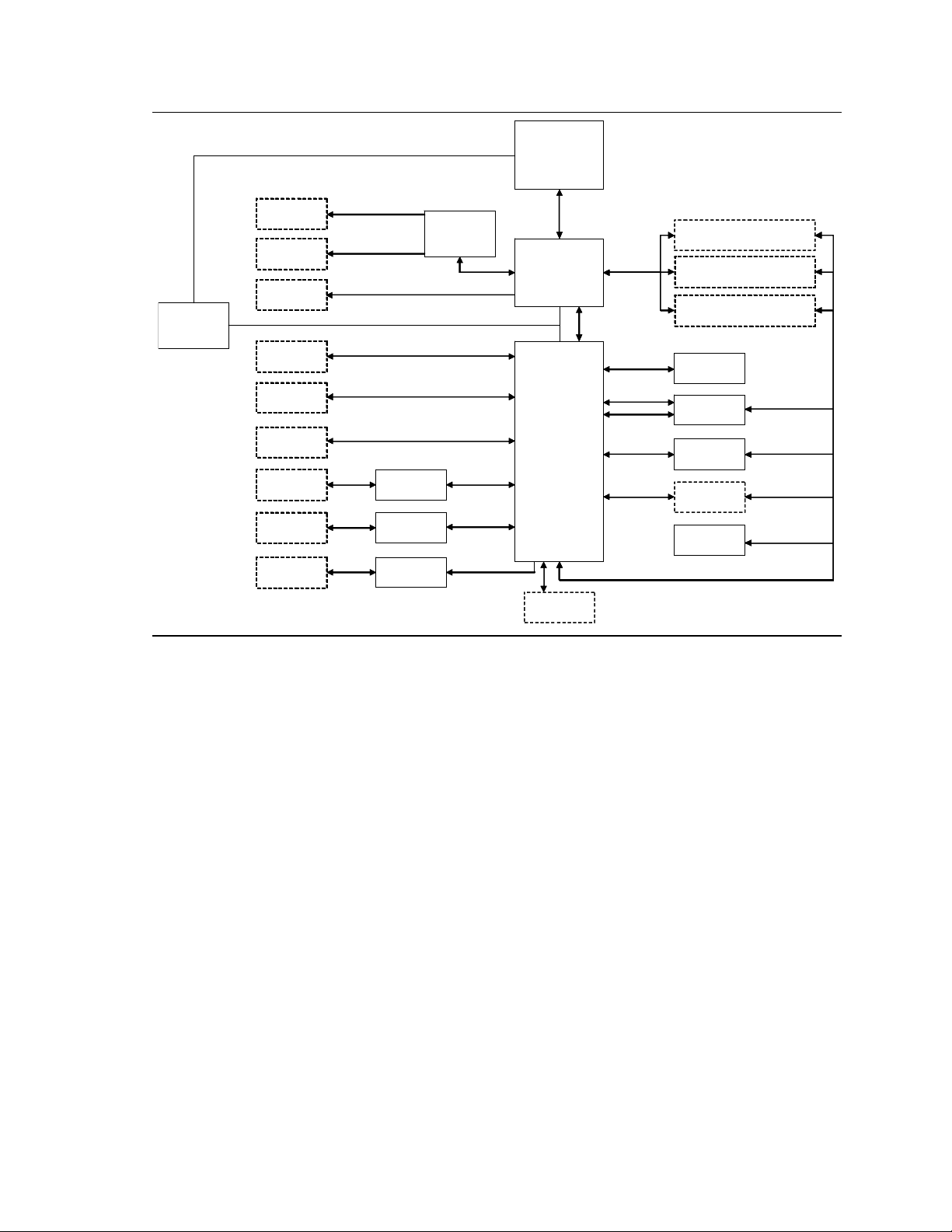
Intel Desktop Board DX58SO2/DX58OG consists of the Intel Core i7 processor and the
Intel X58 Chipset including the IOH (I/O Hub) and th e ICH10R (I/O Controller Hub).
The Intel Core i7 processor integrates the system memory controller and accesses
DDR3 memory through three independent memory channels. The IOH provides
support for two PCI Express* x16 graphics slots, the PCI Express x4 slot, and connects
to the processor via the Quick Path Interconnect™ (QPI™) bus. The ICH10R provides
support for SATA, USB, and other system interfaces in addition to communicating with
the IOH via the DMI bus.
BIOS performance tuning controls include the host clock, processor turbo ratios, QPI
data rate, IOH, and processor and memory voltages. A simplified system block
diagram is shown in Figure 2.1.
9
Page 10
Intel DX58SO2/DX58OG Desktop Board Performance Tuning Guide
LGA 1366
LGA 1366
Processor
Processor
PCIe x8
PCIe x8
PCIe x8
PCIe x8
PCIe x16
PCIe x16
(DX58SO2 only)
(DX58SO2 only)
PCIe x16
PCIe x16
PCIe x1
PCIe x1
PCIe x1
PCIe x1
SATA Interface
SATA Interface
eSATA
eSATA
3.0 Gb/s
3.0 Gb/s
Controller
Controller
eSATA
eSATA
6.0 Gb/s
6.0 Gb/s
Controller
Controller
USB 3 .0
USB 3 .0
Controller
Controller
Mult iple xer
Mult iple xer
PCIe x16
PCIe x16
PCIe x1
PCIe x1
PCIe x1
PCIe x1
PCIe x1
PCIe x1
Qu ick P a t h
Qu ick Pat h
Interconnect™
Interconnect™
Intel X58
Intel X58
I/O Hub (I OH)
I/O Hub (I OH)
DMI
DMI
Inte l IC H10 R
Inte l IC H10 R
I/O Controller
I/O Controller
Hub (ICH)
Hub (ICH)
USB 2.0
USB 2.0
Connec tor
Connec tor
Tri-Channel
Tri-Channel
Memory Bus
Memory Bus
PCIe x1
PCIe x1
PCIe x1
PCIe x1
PCIe x1
PCIe x1
PCI
PCI
Host C lo ck
Host Clock
133 MHz
133 MHz
(Default)
(Default)
PCIe x16
PCIe x16
Connec tor
Connec tor
PCIe x16
PCIe x16
Connec tor
Connec tor
PCIe x16
PCIe x16
Connec tor
Connec tor
PCIe x1
PCIe x1
Connec tor
Connec tor
PCIe x1
PCIe x1
Connec tor
Connec tor
SATA
SATA
3 Gb/ s
3 Gb/ s
Connec tor
Connec tor
SATA
SATA
3.0 Gb/s
3.0 Gb/s
Connec tor
Connec tor
SATA
SATA
6.0 Gb/s
6.0 Gb/s
Connec tor
Connec tor
USB 3.0
USB 3.0
Connec tor
Connec tor
LCI
LCI
DIMM 4 Channel A, DIMM 0
DIMM 4 Channel A, DIMM 0
DIMM 1 Channel A, DIMM 1
DIMM 1 Channel A, DIMM 1
DIMM 5 Channel A, DIMM 0
DIMM 5 Channel A, DIMM 0
DIMM 2 Channel A, DIMM 1
DIMM 2 Channel A, DIMM 1
DIMM 6 Channel A, DIMM 0
DIMM 6 Channel A, DIMM 0
DIMM 3 Channel A, DIMM 1
DIMM 3 Channel A, DIMM 1
1394a
1394a
Controller
Controller
LAN
LAN
Controller
Controller
LAN
LAN
Controller
Controller
(DX58SO2 Only)
(DX58SO2 Only)
PCI
PCI
Connector
Connector
Hardware
Hardware
Monitoring/Fan
Monitoring/Fan
Control ASIC
Control ASIC
SMBus
SMBus
Figure 2.1. Intel Desktop Board DX58SO2/DX58OG Simplified Block Diagram
10
Page 11

Intel DX58SO2/DX58OG Desktop Board Performance Tuning Guide
3 Intel Desktop Board DX58SO2/DX58OG
Performance Tuning Using BIOS Setup
3.1 Hardware Considerations for Performance Tuning
Performance tuning in this guide was developed using Intel Desktop Board DX58SO2
and Intel Desktop Board DX58OG using both Intel
Extreme Edition processors. The processor was air cooled using an Intel E88216-001
fan heat sink.
®
Core™ i7 Extreme Edition and non-
3.1.1 Board
The additional processor voltage regulator phases and heat pipe cooling on Intel
Desktop Board DX58SO2 enable greater performance tuning capability in comparison
to Intel Desktop DX58OG.
3.1.2 Processor
Intel Desktop Board DX58SO2 and Intel Desktop Board DX58OG support Intel Core i7
processors. These processors include the Intel Core Extreme Edition processors, the
Intel Core i7 processors, and some Intel
controls are available with the Extreme Edition processors. With non-Extreme Edition
Intel Core processors, turbo ratios are locked and not adjustable. A list of supported
processors for the boards can be found at:
Intel Desktop Board DX58SO2
http://processormatch.intel.com/CompDB/SearchResult.aspx?BoardName=DX58SO2
Intel Desktop Board DX58OG
http://processormatch.intel.com/CompDB/SearchResult.aspx?BoardName=DX58OG
®
Xeon® processors. All performance tuning
3.1.3 Memory
Memory modules with XMP profiles have preprogrammed optimized performance
settings created by the manufacturer that can be selected in the BIOS. Using XMP
profiles can simplify memory performance tuning. Capability for memory performance
tuning will likely be limited if low speed, low cost DIMMs are being used.
For specific memory support information, see the Technical Product Specification for
your board located at http://downloadcenter.intel.com
.
11
Page 12

Intel DX58SO2/DX58OG Desktop Board Performance Tuning Guide
3.1.4 Power Supply
Performance tuning will increase the demand on the system power supply. Lower
wattage power supplies may have insufficient capacity once the load imposed by the
board, graphics card(s), the processor cooler, other system fans, hard drives, CD/DVD
drives, and other accessories are combined. Inadequate power supply capacity will
result in system shutdowns and stability problems when performance tuning is
attempted or later when a performance tuned system is being operated.
For Intel Desktop Board DX58SO2/DX58OG, the power supply should have at least
200 watts of unused capacity to accommodate the typical needs of performance tuned
processor and memory. For more extreme performance, additional capacity beyond
the extra 200 watts will be needed. Additional power supply capacity will also be
needed if a performance tuned graphics card or pair of graphics cards will be included
in the system. Consult the graphics card manufacturer’s specifications to determine
these additional capacity requirements.
3.1.5 System Cooling
Performance tuning will result in additional system heat generation. Increased cooling
capability may be required to allow performance tuning and stable operation of a
performance tuned system. Considerations for increasing cooling capability may
include, but are not limited to, chassis type, selection of air or liquid cooling, processor
cooler design, memory module design, and overall system airflow. Extreme
performance tuning requires system designs with increasingly sophisticated cooling
capabilities. It is beyond the scope of this guide to provide detailed recommendations
for system cooling.
CAUTION
Cooling induced moisture condensation from refrigerant systems, dry ice, liquid
nitrogen, or other uncommon cooling methods will result in risk for electrical shorting
and subsequent damage to the board and/or the system.
3.2 Suggestions for Effective Tuning
Optimal results will occur if tuning efforts are directed appropriately. For example, if
performance improvements with a certain gaming application are desired, then tuning
efforts should be directed at the system resources used by the game. If the game
software has intensive processor computational work, but relatively l ight demands on
system memory, then focusing performance tuning efforts on memory will not yield
significant improvements.
System resource (processor, memory, etc.) utilization can be determined by running
your software application while monitoring resource usage. Resource usage can be
monitored with the Intel Extreme Tuning Utilit y. Also, your software supplier should
be able to provide information about system resource utiliza tion with their application.
12
Page 13

Intel DX58SO2/DX58OG Desktop Board Performance Tuning Guide
Video graphics performance increases may be needed to improve the overall
performance of gaming software. The supplier of the graphics card should be
contacted for information about performance tuning their hardware. External graphics
tuning is specific to the graphics card manufacturer and cannot be done using either
the Intel Desktop Board DX58SO2/DX58OG BIOS or the Intel Extreme Tuning Utility.
Keeping a written log of performance tuning settings and the results w ill be extremely
helpful. Your tuning efforts will be much more efficient if you can refer to the log for
settings that you have already tried. If you need to restore BIOS parameters to
something that worked previously, then information recorded in the log can be used.
The log will also be convenient for entering parameters if prof iles will be setup using
the Intel Extreme Tuning Utility.
The user may have different performance setting profiles that are needed, depending
on the software applications being run. The Intel Desktop Board DX58SO2/DX58OG
BIOS supports multiple BIOS parameter settings (profiles). Storage and retrieval of
BIOS profiles is described in Section 3.5.3.13.
3.3 Accessing BIOS Setup
The BIOS setup screen can be accessed at system startup by pressing the F2 key at
the BIOS screen prompt. It is advisable to run the most recent revision of the BIOS to
ensure that performance features are at the highest level of optimization. The latest
version BIOS can be obtained from http://downloadcenter.intel.com
loading the BIOS into the board can also be found at this link.
Before initiating performance tuning, ensure that the BIOS setup defaults have been
loaded by pressing the F9 key while in BIOS setup mode and then pressing the F10
key to save those settings.
NOTE
If you configured your system to boot to RAID or IDE, pressing the F9 key will reset
your SATA configuration to AHCI. If you are not using AHCI, be sure to restore your
SATA configuration prior to pressing the F10 key to save the settings.
. Instructions for
3.4 Recovering from an Unstable System
Should performance values be set beyond the point of stable system operation, the
system may exhibit a failure to boot, a blue screen, a system hang, or a recovery
screen as described in the sections below. Exceeding the system stability l imit s is a
normal, expected occurrence during the performance tuning process and there are
multiple reliable and easy to use options for restoring system operation as described in
the following subsections.
13
Page 14

Intel DX58SO2/DX58OG Desktop Board Performance Tuning Guide
3.4.1 Hardware Watchdog Timer
A hardware watchdog timer is included as part of the board circuitry and is enabled by
default in the BIOS. This timer will automatically enable the board to startup if
unstable system operation or a failure to boot is detected. If the watchdog timer
detects an issue, the screen shown in Figure 3.1 will be displayed. In addition, on
Intel Desktop Board DX58SO2/DX58OG, at the Diagnostic LED bank, the red
WD Fire/B2B LED will light when the Watchdog Timer is activated. The user can then
go into the BIOS screen and manually reset performance parameters or use the F9 key
to reset all BIOS defaults to restore system stability. This process can be repeated
over and over, so if the user’s parameter changes do not restore system stability, the
watchdog timer will again intervene and allow the user another opportunity to adjust
the BIOS settings. The watchdog timer works in many, but not all, cases. If the
watchdog timer did not detect an issue or was disabled by the user, then one of the
alternate recovery options described in Section 3.4.2, 3.4.3, or 3.4.4 can be used.
14
Figure 3.1. Screen Displayed When the Watchdog Timer
Detects an Issue
Page 15

Intel DX58SO2/DX58OG Desktop Board Performance Tuning Guide
3.4.2 Back to BIOS (B2B) Button
A second recovery option is to use the Back to BIOS button that is located on the
board’s back panel. This button provides a convenient method of invoking the BIOS
setup menu, as shown in Figure 3.2, in a safe, bootable mode without opening the
system chassis to access the BIOS configuration jumper. When the Back to BIOS
button is depressed, both the button and the red WD Fire/B2B LED located on the Intel
Desktop Board DX58SO2/DX58OG Diagnostic LED bank will light. The F9 key can then
be used to restore all BIOS settings to defaults at this point or specific performance
settings can be individually revised by the user to restore system stability. Additional
information regarding this feature can be found in the Intel Desktop Board DX58SO2
(or DX58OG) Product Guide.
Figure 3.2. Screen Displayed When the System is Started with
the Back to BIOS Button Depressed
3.4.3 BIOS Configuration Jumper
A third recovery option is to use the BIOS configuration jumper on the board to force
the board to boot to BIOS Setup in a safe mode. The user will need to open their
system chassis to access this jumper. Refer to the Intel Desktop Board DX58SO2 (or
DX58OG) Product Guide for additional information on using the BIOS jumper for
resetting purposes.
15
Page 16

Intel DX58SO2/DX58OG Desktop Board Performance Tuning Guide
3.4.4 Remove Power and Reboot
For a system hang, resetting your system or removing, reapplying AC power, and
rebooting will allow the system to initiate a reboot. Note that BIOS settings will
remain unchanged during a reset or removal of AC power. The watchdog timer, the
Back to BIOS button, the BIOS configuration jumper, or pressing the F2 key at the
setup screen prompt will allow the user to adjust performance settings in BIOS to
restore system stability.
3.5 Intel Desktop Board DX58SO2/DX58OG Performance Tuning Process
Simplified tuning processes for use with either Intel Extreme Edition or non-Extreme
Edition processors are included below. The simplified tuning process allows users to
make a significant increase in performance in a few easy steps. More in depth tunin g
procedures are included in Section 3.5.3 of this guide for users wanting to increase
performance levels beyond those obtained with the simplif ied tuning processes.
3.5.1 Simplified Tuning Process for Intel® Core™ i7
Extreme Edition Processors
These performance settings are applicable with the Intel Core i7 E xtreme Edition
processors. This includes the Intel Core i7-990X, i7-980X, i7-975, and i7-965
processors. An Intel tower model E88216-001 fan heatsink was used for processor
cooling with the performance settings listed below.
Performance Settings
1. Power up the system and press the F2 key to go into BIOS setup mode.
2. These instructions assume default BIOS settings are present and only changes
from those defaults are listed below. Optionally, the F9 key may be pressed to
load Setup Defaults. If other BIOS configuration changes have been previously
made (i.e., SATA Configuration), they will need to be reapplied after loading Setup
Defaults.
3. From the BIOS Performance menu where the disclaimer asks if you wish to
continue, select Yes. This will enable the Performance screen to be displayed.
4. Scroll down and select the Processor submenu. From the Processor Overrides
screen, make the following settings:
a. Set the Processor Voltage Override Type to Dynamic.
16
b. Set the Dynamic Processor reference Voltage to 1.3500 volts.
c. Set TDC current limit override to 200 amps.
d. Set TDP Power Limit Override 150 watts.
e. Set core ratio limits (also referred to as multipliers or Turbo ratios) to 31 for
each processor core.
Page 17

Intel DX58SO2/DX58OG Desktop Board Performance Tuning Guide
5. If you have compatible XMP based memory, an XMP profile can be selected from
the Memory settings BIOS subpage under the performance settings. See
http://www.intel.com/consumer/game/extreme-memory.htm
for more information
on XMP memory.
6. Press the F10 key to save settin g s and exit BIOS. The system will automatically
reboot with the new performance settings enabled. If the system fails to boot, see
Section 3.4 on recovering from an unstable system.
3.5.2 Simplified Tuning Process for Intel® Core™ i7 NonExtreme Edition Processors
These performance settings will result in a processor frequen cy of about 4 GHz and are
applicable with the Intel Core i7 non-Extreme Edition processors. This includes the
Intel Core i7-970, i7-960, i7-950, i7-940, i7-930, and i7-920 processors. An Intel
tower model E88216-001 fan heatsink was used for processor cooling with these
performance settings.
Performance Settings
1. Power up system and press the F2 key to go into BIOS setup mode
2. These instructions assume default BIOS settings are present and only changes
from those defaults are listed below. Optionally, the F9 key may be pressed to
load Setup Defaults. If other BIOS configuration changes have been previously
made (i.e., SATA Configuration), they will need to be reapplied after loading Setup
Defaults.
3. From the BIOS Performance menu where the disclaimer asks if you wish to
continue, select Yes. This will enable the Performance screen to be displayed.
4. Scroll down to the Processor submenu and set the Processor Voltage Override type
to Dynamic and set the Dynamic Processor Reference Voltage to 1.3500 volts.
Press the ESC key to go back to the Performance screen.
5. Scroll up to the Host Clock Frequency (MHz) menu and set the Host Clock
Frequency according to the table below.
Processor Processor Frequency Host Clock Frequency Setting
Intel Core i7-970 3.20 GHz 153 MHz
Intel Core i7-960 3.20 GHz 153 MHz
Intel Core i7-950 3.06 GHz 160 MHz
Intel Core i7-940 2.93 GHz 167 MHz
Intel Core i7-930 2.80 GHz 173 MHz
Intel Core i7-920 2.66 GHz 181 MHz
17
Page 18

Intel DX58SO2/DX58OG Desktop Board Performance Tuning Guide
6. Increasing the host clock f requency will increase the memory frequency. It may be
necessary to reduce the memory speed to restore memory stability. This can be
done in the Performance Memory Profiles submenu by selecting Manual – User
Defined and then scrolling down to the memory multiplier. The memory frequency
can be reduced by selecting a lower memory multiplier value.
7. If you have compatible XMP based memory, an XMP profile can be selected from
the Memory settings BIOS subpage under the performance settings. Note that XMP
profile memory frequencies will also be increased when the host clock frequency is
increased. See http://www.intel.com/consumer/game/extreme-memory.htm
more information on XMP memory.
8. Press the F10 key when you are ready to save settings and exit BIOS. The system
will automatically attempt reboot with the new performance settings enabled. If
the system fails to boot, see Section 3.4 on recovering from an unstable system.
3.5.3 Detailed Performance Tuning Process Steps
There are various sequences of steps possible for doing board performance tuning.
The approach presented in this guide is a general starting point, but may not be
optimal for all cases.
for
Intel Desktop Board DX58SO2 and Intel Desktop Board DX58OG allow performance
tuning using the host clock, turbo ratios, or a combination of both. The applicable
tuning method depends on what type of processor is being used. If a non-Extreme
Edition processor is being used, then performance tuning will be done by increasing
the frequency of the host clock. If an Extreme Edition processor is being used, then
performance tuning using turbo ratios, host clock settings, or a combination of turbo
ratios and host clock settings are options.
A full processor and memory tuning sequence consists of the steps suggested below.
Depending on your objectives, it may not be necessary to complete all of the steps in
this sequence. More discussion about these steps is included in Sections 3.5.3.1
through 3.5.3.13. Detailed descriptions of the various BIOS controls are included in
Appendix A, Table A-1. Checking system stability appears frequently du ring this
sequence. This check ensures that the work done up to that point will provide stable
system performance. If instability is encountered, the source of the problem can be
more easily determined if regular stability checks have been completed.
Performance tuning is an iterative process. The settings made for one parameter may
affect which settings will work for another paramet er. For example, increasing the
host clock frequency may require that previous tuning adjustments for system
memory be revised to maintain memory stability. The sequence of steps below was
designed to minimize the number of iterations required for performance tuning.
1. Configure the BIOS for performance tuning.
2. Set processor overrides (voltage, current and power).
3. Decrease memory speed.
4. Decrease QPI data rate.
5. Increase core ratio limits and/or host clock frequency.
18
Page 19

Intel DX58SO2/DX58OG Desktop Board Performance Tuning Guide
6. Check stability.
7. Tune memory.
8. Recheck stability.
9. Tune QPI.
10. Recheck stability.
11. Balance settings between processor, QPI, and memory.
12. Recheck stability.
13. Fine tune voltage and power settings.
14. Recheck stability.
15. Archive performance settings.
3.5.3.1 Configure BIOS for Performance Tuning
Power up the system and press the F2 key at the BIOS screen prompt to go into BIOS
setup mode.
3.5.3.1.1 Performance Disclaimer
Performance tuning options are located in the menu section labeled “Performance”.
Reading and agreeing to the disclaimer by selecting “Yes”, as shown in Figure 3.3,
allows the detailed BIOS performance menu to be displayed.
Figure 3.3. BIOS Performance Tuning Disclaimer
19
Page 20
Intel DX58SO2/DX58OG Desktop Board Performance Tuning Guide
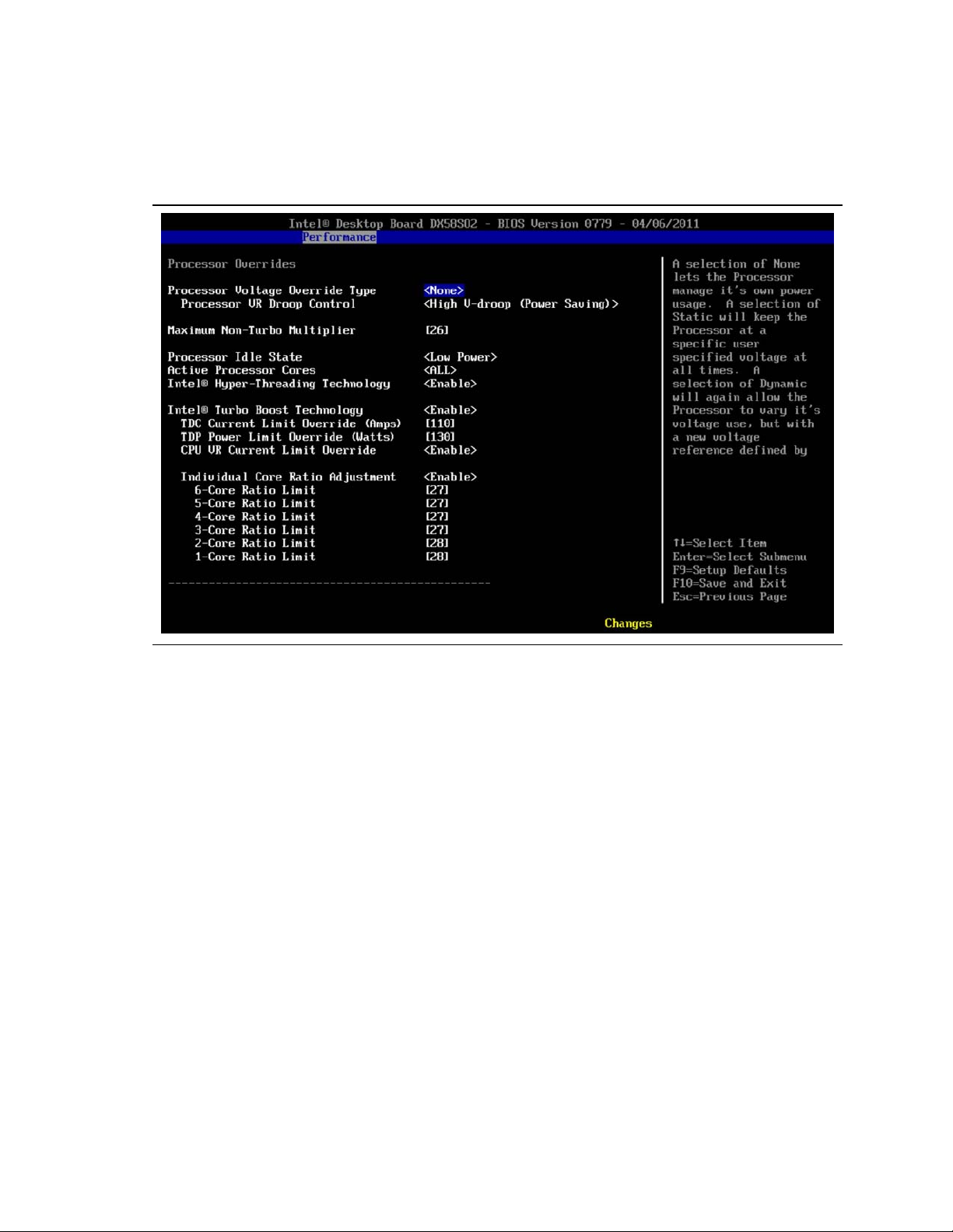
3.5.3.2 Set Processor Overrides (Voltage, Current, and Power)
From the Performance page, processor tuning options are under the Processor
submenu section shown in Figure 3.4.
Figure 3.4. Processor Overrides BIOS Screen Showing Default Settings with
an Intel Core i7-990X Extreme Edition Processor Installed
3.5.3.2.1 Processor Voltage Override Type
For CPU Override Type, select Static. This setting prevents dynamic adjustments that
could confuse tuning efforts. At the end of the tuning procedure, this setting can be
changed to dynamic for more energy efficient operation.
3.5.3.2.2 Processor Voltage Override
At the CPU Voltage Override, increase the voltage setting. This needs to be done to
provide the extra voltage to support performance tuning. The amount of voltage
increase needed depends on the amount of performance increase that is desired. The
objective is to provide just enough voltage so the processor can sustain the desired
level of performance. Use the voltage provided in the simplified tuning procedures
described in Section 3.5.1 or Section 3.5.2, as a starting point. Note that high voltage
settings may potentially cause processor damage. At the end of the tuning process,
the voltage will be reduced to the lowest level that provides stability.
20
Page 21

Intel DX58SO2/DX58OG Desktop Board Performance Tuning Guide
3.5.3.2.3 Processor VR Droop Control
Set Processor VReg Droop Control to Low V-droop (Performance) if you are attempting
to maximize processor performance. If you are attempting moderate performance
increases, then the Mid or the High V-droop (Power Saving) selection is acceptable.
3.5.3.2.4 Maximum Non-Turbo Multiplier
Leave this multiplier at the default setting provided in the BIOS. Note that this setting
may be different depending on the processor that is being used.
3.5.3.2.5 Processor Idle State
Leave setting at Low Power.
3.5.3.2.6 Active Processor Cores
Leave setting at ALL.
®
3.5.3.2.7 Intel
Hyper-Threading Technology
Leave setting at Enable.
®
3.5.3.2.8 Intel
Turbo Boost Technology
Leave setting at Enable.
3.5.3.2.9 TDC Current Limit Override (Amps)
Set the TDC Current Limit Override (Amps). Use the amps provided in the simplified
tuning procedures, Section 3.5.1, as an initial starting point. This control will not be
available with some processors.
3.5.3.2.10 TDP Power Limit Override (Watts)
Set the TDP Power Limit Override (Watts). Use the watts provided in the simplified
tuning procedure, Section 3.5.1, as an initial starting point. This control will not be
available with some processors.
3.5.3.2.11 CPU VR Current Limit Override
Leave set to Enable.
3.5.3.3 Decrease Memory Speed
The memory speed is initially being reduced to help prevent subsequent host clock
changes from increasing the memory speed to where it becomes unstable. The
memory speed will be reset later in the performance tuning process.
From the Performance menu, scroll down to the Memory submenu and press <Enter>.
3.5.3.3.1 Performance Memory Profiles
Reset this to Manual – User defined.
21
Page 22
Intel DX58SO2/DX58OG Desktop Board Performance Tuning Guide
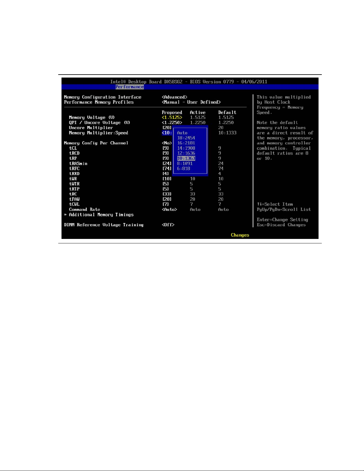
3.5.3.3.2 Memory Multiplier: DDR3 Speed
Select the lowest memory multiplier speed from the list as shown in Figure 3.5.
Figure 3.5 BIOS Screen Showing Memory Multiplier Selection Options
22
Page 23

Intel DX58SO2/DX58OG Desktop Board Performance Tuning Guide
3.5.3.4 Decrease QPI Data Rate
The QPI data rate is initially being reduced to help prevent subsequent host clock
changes from increasing the QPI bus speed to where it becomes unstable. The QPI
speed will be increased later in the performance tuning process.
From the Performance menu, scroll down to the Bus submenu and press <Enter>. On
the Bus Overrides screen, scroll down to QPI Data Rate and set the data strap to
4.8 GT/s as shown in Figure 3.6. Note that with some processors, the data strap may
already be locked at 4.8 GT/s.
Figure 3.6. BIOS Screen Showing QPI Data Rate Change Options
3.5.3.5 Increase Core Ratio Limits (Also Referred to as Multipliers
or Turbo Ratios) and/or Host Clock Frequency
NOTE
Only Extreme Edition processors allow modifying the core ratio limits (also referred to
as the multiplier or turbo ratios). Skip this section if you are using a non-Extreme
Edition processor since their multipliers are not adjustable. If you have already
increased the host clock frequency as much as possible, you may not be able to
increase the multipliers without processor stability issues occurring.
23
Page 24

Intel DX58SO2/DX58OG Desktop Board Performance Tuning Guide
3.5.3.5.1 Increase Core Ratio Limits
Gradually increase the multiplier for each of the core ratio limits. Four core processors
will have core ratio settings for cores 1-4. Six core processors will have core ratio
settings for cores 1-6. The ratio multiplied by the host clock frequency determines the
processor frequency that will be obtained. Making these settings is a trial and error
process. If ratios are set too high, the processor will be unstable and will not operate.
Reducing the ratios or increasing the CPU Voltage Override (Section 3.5.3.2.2) and/or
the TDC Current Limit Override (Amps) (Section 3.5.3.2.9) can be used to restore
processor stability.
For the default host clock setting of 133 MHz, Table 3-1 shows the resulting processor
frequency with various multiplier values.
Table 3-1. Resulting CPU Frequency Values for Various Multipliers
Multiplier Resulting CPU Core Frequency (GHz)
20 2.66
21 2.80
22 2.93
23 3.06
24 3.20
25 3.33
26 3.46
27 3.60
28 3.72
29 3.86
30 4.00
31 4.12
32 4.26
33 4.40
34 4.52
35 4.66
24
Page 25
Intel DX58SO2/DX58OG Desktop Board Performance Tuning Guide
3.5.3.5.2 Increase Host Clock Frequency
From the BIOS performance screen, gradually increase the frequency of the host clock
until the board is unable to boot. If you are using a non-Extreme Edition processor,
use the settings provided in the table included with the simplified tuning procedure,
Section 3.5.2 as an initial starting point.
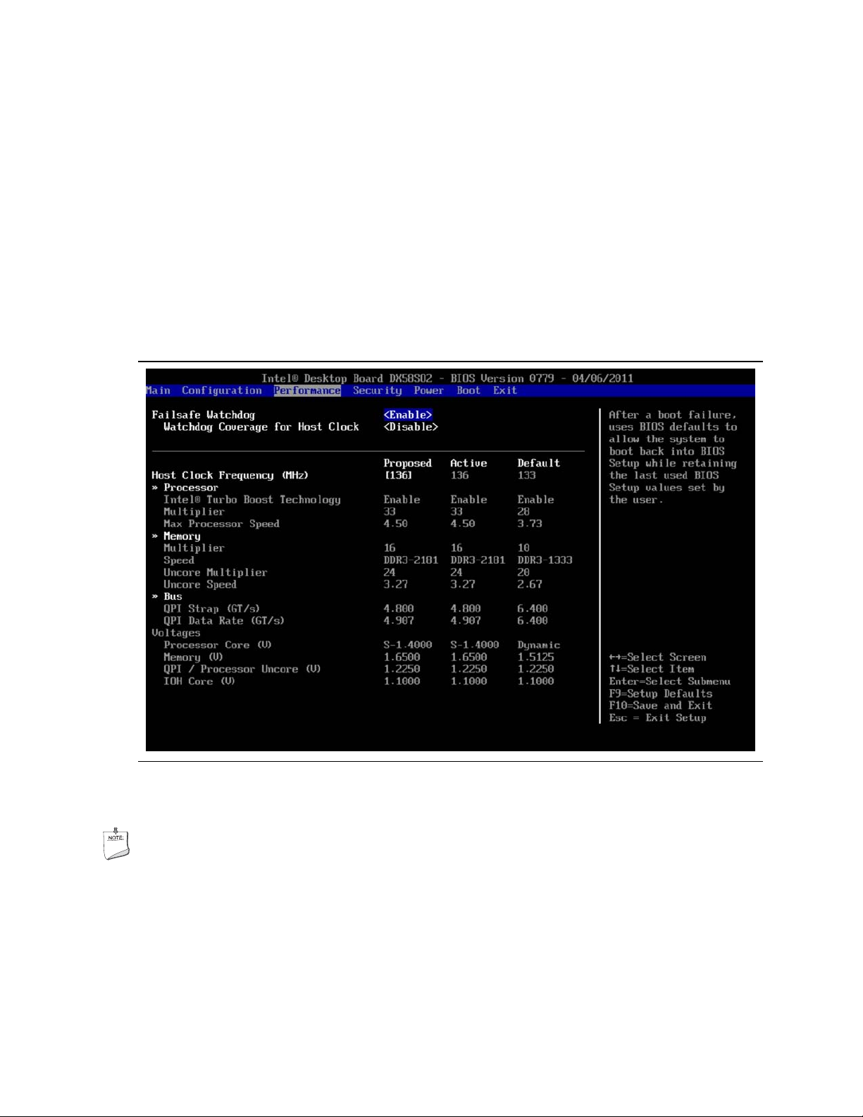
In Figure 3.7, the host clock frequency was changed using the BIOS screen as shown.
The column labeled “Proposed” shows the results of increasing the system clock
setting from 133 MHz to 136 MHz with the resulting processor speed increase from
3.47 GHz to 4.50 GHz ((core ratio multiplier of 33) x (136 MHz host clock frequency) =
4.488 or about 4.50 GHz).
Figure 3.7. Performance BIOS Screen Showing Multiplier (Core Ratios)
Increased to 33 and Host Clock Frequency Increased to 136 MHz
NOTE
Since the speeds of the other board subsystems are derived from the host clock, the
QPI data rate and memory speed will be increased as well.
25
Page 26

Intel DX58SO2/DX58OG Desktop Board Performance Tuning Guide
3.5.3.6 Check Stability
Establishing stability should be done frequently during the performance tuning
process. A good initial check of system stability is to see if the system can boot into
the operating system. If the system has become unstable, refer to Section 3.4 for
recovery options.
When the system can successfully boot into the operating system, various software
applications can be used to stress the processor, memory, and other subsystems.
When processor cores are idle, the Intel Core processors will operate at a reduced
multiplier value. While running in the operating system, the application of a heavy
load will bring all processor cores out of the idle and run them at the multiplier values
selected in the BIOS setup. Heavy loads can be applied by using commonly available
processor and memory stress testing software.
During stress testing, look for erratic software behavior, a blue screen or a system
hang. Any of these are indications of system instability. Solutions to instability
include revising the performance settings described in the various areas of Section 3.5.
When processor stability issues occur, revising host clock frequency settings, QPI data
rates, voltage settings, multipliers, or a combination of these changes will be required.
The Intel Extreme Tuning Utility includes processor and memory stress testing
capabilities in addition to allowing the processor temperature to be monitored as
shown in Figure 3.8. Being able to stress test subsystems such as the processor and
memory with relative independence is helpful. This enables you to determine which
subsystem exhibits instability so you know which group of performance parameters to
revise. Revising processor parameters will not improve stability if memory settings
are actually causing the issue.
If processor temperature is steadily increasing or processor throttling is occurring
during stress testing, then additional tuning or improved cooling is needed.
After system stability has been established with stress testing software, confirm
stability while running the software applications (games, video editing, etc.) that you
normally use.
26
Page 27

Intel DX58SO2/DX58OG Desktop Board Performance Tuning Guide
Figure 3.8. Intel Extreme Tuning Utility Showing Passing Stress Test Result
on a Performance Tuned System Using an Intel Core i7-990X Processor and
XMP 2133 MHz Memory
3.5.3.7 Tune Memory
A wide variety of memory timing parameters can be adjusted in the BIOS setup as
described in the sections below. See Appendix B for a summary description of
memory settings and their effects.
In addition, DIMM socket population will also affect system performance. Intel
Desktop Board DX58SO2/DX58OG has three independent memory channels which are
indicated by blue or black memory DIMM sockets. For best performance, all sockets
should be populated with memory matched by manufacturer, size, speed, and type.
This matching allows the processor to access data across each of the memory channels
concurrently. When installing memory, insert memory in the blue DIMM connectors
first. If more than three memory modules will be installed, install the additional
memory in the black DIMM connectors.
27
Page 28

Intel DX58SO2/DX58OG Desktop Board Performance Tuning Guide
3.5.3.7.1 XMP Memory Profiles
Although each memory parameter can be modified individually, the easiest method of
optimizing performance is to use memory that supports Extreme Memory Profiles
(XMP). These profiles are preprogrammed by the manufacturer into the memory
module itself and can be selected from the XMP profile list as shown in Figure 3.9.
These profiles are validated by the manufacturer and are optimized for both
performance and system stability. The listed XMP profiles will vary depending on the
memory being used.
CAUTION
Operating memory at voltages higher than JEDEC approved 1.5 volts may reduce
processor life.
28
Figure 3.9. BIOS Screen Showing Selection of XMP 2133 Profile
From the Options List
Page 29

Intel DX58SO2/DX58OG Desktop Board Performance Tuning Guide
3.5.3.7.2 Memory Performance Options
The Memory Configuration BIOS page, shown in Figure 3.10 contains all the memory
timing options that can be adjusted.
NOTE
For each of the timings, except the multipliers, lower number settings correspond with
higher performance and potential memory system instability.
Figure 3.10. BIOS Memory Performance Settings Screen
3.5.3.7.3 Determining Memory Frequency
On the DX58SO2/DX58OG board, memory frequency is controlled directly from the
host clock. The default host clock frequency is 133.3 MHz. Increasing the host clock
frequency affects the memory frequency according to the following formula:
Memory frequency = (memory multiplier) * (percent increase in host clock
frequency) * (133.3 MHz)
Example: If the host clock frequency was increased by 1% and a multiplier of 8 was
being used, then the new memory frequency would be (8) * (1.01) * (133.3 MHz) =
1077 MHz
For the default 133.3 MHz memory clock, the resulting memory frequency with various
multipliers is shown in Table 3-2.
29
Page 30

Intel DX58SO2/DX58OG Desktop Board Performance Tuning Guide
Table 3-2. Resulting Memory Frequency Values for Various Multipliers
Multiplier Resulting Memory Frequency (MHz)
8 1066
10 1333
12 1600
14 1866
16 2133
3.5.3.7.4 Going Beyond XMP Profiles
Using XMP profiles provides much of the obtainable memory performance benefit with
minimum effort. Further increases in memory performance can be obtained by setting
the tCL, tRCD, tRP, and tRAS parameters to their maximum values and increasing the
system clock in small increments while checking system stability between each clock
increase until the system becomes unstable. Note that system clock ch anges will also
affect the processor frequency and may affect processor stability.
Once the point of memory instability has been reached with syst em clock increases,
reduce the system clock frequency until the memory is once again stable (the board
will boot again). Next, reduce the tCL, tRCD, tRP, and tRAS parameter values until the
system once again becomes unstable, then increase the values by one increment.
3.5.3.8 Tune QPI
If your processor allows, attempt to increase the QPI data rate using the settings
shown earlier in Figure 3.6.
The QPI data rate can be determined according to the following formula:
QPI Data Rate = (QPI data strap) * (percent increase in host clock)
Example: If a QPI data strap of 6.4 GT/s was set and the host clock frequency was
increased by 1%, then the resulting QPI data rate would be (6.4) * (1.01) =
6.44 GT/s.
3.5.3.9 Recheck Stability
Recheck stability as described in Section 3.5.3.6.
30
Page 31

Intel DX58SO2/DX58OG Desktop Board Performance Tuning Guide
3.5.3.10 Balance Settings Between Processor, Memory, and QPI
Best system performance will typically occur by maximizing processor frequen cy
followed by memory frequency and then finally QPI data rate. Intel Extreme Edition
processors have greater flexibility for maximizing overall system performance because
both core ratios and host clock frequency settings can be used for tuning.
Since Intel non-Extreme Edition processors only support host clock frequency changes,
balancing overall system performance will likely require some performanc e tradeoffs
between the processor, memory, and QPI to be made. If a little more memory
performance is desired, reducing the host clock frequency slightly may allow a higher
memory multiplier to be used and result in greater memory speed. If the host clock
frequency is reduced, the processor and QPI speeds will also be reduced. These are
the typical adjustments and tradeoffs that are made during this part of the
performance tuning process.
If you are attempting to maximize the performance for a particular software
application, you may want to compare various possible tradeoff options an d determine
where the best software performance occurs.
3.5.3.11 Fine Tune Voltage and Power Settings
The processor override voltage type can now be set to dynamic if additional system
energy efficiency is desired. Note that the processor voltage override value may also
need to be revised if changing from static to dynamic. Gradually reduce voltage and
power settings that were made in the applicable portions of Section 3.5.3.2. When
instability is encountered, increase the setting(s) as needed to restore stable
operation.
3.5.3.12 Recheck Stability
Recheck stability as described in Section 3.5.3.6.
3.5.3.13 Archive Performance Settings
The Intel Desktop Board DX58SO2/DX58OG BIOS allows storing multiple BIOS profiles
(groups of BIOS parameter settings). These profiles may be retrieved or deleted as
desired by the user. BIOS profiles may be saved by going to the BIOS Exit menu
screen and scrolling down to Save BIOS Profile and selecting New BIOS Profile as
shown in Figure 3.11. Type the desired name for the New BIOS profile and then press
<Enter> to save the profile.
31
Page 32

Intel DX58SO2/DX58OG Desktop Board Performance Tuning Guide
Figure 3.11. Storing Performance Profiles in the BIOS
The Load BIOS profile option allows users to load profiles that have been previously
stored in the BIOS. BIOS profiles may be retrieved by going to the BIOS Exit menu
screen and scrolling down to Load BIOS Profile and selecting the BIOS profile from the
list of stored profiles that appears.
32
Page 33

Intel DX58SO2/DX58OG Desktop Board Performance Tuning Guide
4 Performance Tuning Examples
4.1 Intel Core i7-990X Extreme Edition Processor
on Intel Desktop Board DX58SO2
Figure 4.1 shows the BIOS settings to achieve a speed of 4.50 GHz with an Intel Core
i7-990X Extreme Edition processor. Core ratios were set at 33 and a host clock setting
of 136 MHz was used. A memory speed of 2133 MHz was set using XMP profiles. With
a host clock setting of 136 MHz, the resulting memory frequency was 2181 MHz. A
QPI data strap of 4.8 GT/s was required in order to allow obtainin g memory operation
at 2181 MHz. No processor thermal throttling occurred during stress testing with
these settings.
These results were obtained on an Intel Desktop Board DX58SO2 with XMP 2133
memory installed. The board was located on an open bench top and the processor
was air cooled using an Intel tower model E88216-001 fan heatsink.
Figure 4.1. 4.50 GHz on an Intel Desktop Board DX58SO2 with an
Intel Core i7-990X Extreme Edition Processor Using Core Ratio
and Host Clock Changes
33
Page 34

Intel DX58SO2/DX58OG Desktop Board Performance Tuning Guide
4.2 Intel Core i7-920 Non-Extreme Edition
Processor on Intel Desktop Board DX58SO2
Figure 4.2 shows the BIOS settings to achieve a processor speed of 4.09 GHz with an
Intel Core i7-920 processor. A host clock setting of 186 MHz was used. A memory
speed of 1489 MHz was obtained using a memory multiplier of 8 when combined with
the host clock setting of 186 MHz. With the Intel Core i7-920 processor, the QPI data
strap is locked at 4.8 GT/s, resulting in an overall QPI data rate of 6. 701 GT/s when
combined with the 186 MHz host clock setting. No processor thermal throttling
occurred during stress testing with these settings.
These results were obtained on an Intel Desktop Board DX58SO2 with XMP 2133
memory installed. The board was located on an open bench top and the processor
was air cooled using an Intel tower model E88216-001 fan heatsink.
34
Figure 4.2. 4.09 GHz on an Intel Desktop Board DX58SO2 with an
Intel Core i7-920 Processor Using Host Clock Changes
Page 35

Intel DX58SO2/DX58OG Desktop Board Performance Tuning Guide
4.3 Intel Core i7-920 non-Extreme Edition
Processor on Intel Desktop Board DX58OG
Figure 4.3 shows the BIOS settings to achieve a processor speed of 3.98 GHz with an
Intel Core i7-920 processor. A host clock setting of 181 MHz was used. A memory
speed of 1448 MHz was obtained using a memory multiplier of 8 when combined with
the host clock setting of 181 MHz. With the Intel Core i7-920 processor, the QPI data
strap is locked at 4.8 GT/s, resulting in an overall QPI data rate of 6. 518 GT/s when
combined with the 181 MHz host clock setting. No processor thermal throttling
occurred during stress testing with these settings.
These results were obtained on a Intel Desktop Board DX58OG with XMP 2133
memory installed. The board was located on an open bench top and the processor
was air cooled using an Intel tower model E88216-001 fan heatsink.
Figure 4.3 3.98 GHz on an Intel Desktop Board DX58OG with an
Intel Core i7-920 Processor Using Host Clock Changes
35
Page 36

Intel DX58SO2/DX58OG Desktop Board Performance Tuning Guide
36
Page 37

Intel DX58SO2/DX58OG Desktop Board Performance Tuning Guide
A Parameter Descriptions for
BIOS Performance Settings
Table A-1. BIOS Performance Settings
Setup Option Description
Host Clock
Frequency
Processor
Voltage Override
Type
Processor VR
Droop Control
Maximum NonTurbo Multiplier
Processor Idle
State
Active Processor
Cores
Intel® HyperThreading
Technology
Intel® Turbo
Boost
Technology
TDC Current
Limit Override
(Amps)
Changing this setting overrides the host clock default frequency of 133.3 MHz. The
host clock frequency x processor ratio = processor speed. Changing the host clock
frequency also changes the memory and QPI speeds.
None: Allows the processor to manage it’s power usage
Static: Overrides the voltage requested by the processor and allows a user sele cted
Processor Static Voltage to be applied at all times. This option disables the dynamic
voltage control of the processor.
Dynamic: Defines an offset that will always be applied to the voltage requested by the
processor. The offset is the difference between the sele cted voltage and the voltage at
power on. For example, if the selected voltage is 1.3 V and the processor powers on at
1.1 V, an offset of 0.2 V will always be added to the voltage requested by the
processor.
This field is enabled when an override voltage is selected. CPU Voltage Droop occurs
when the processor is put under load. Selecting an option to decrease the voltage
droop will generally increase processor stability, but may consume more power and
generate heat.
Used to lower the maximum non-turbo processor speed. The maximum allowed value
is hard coded into your processor model. For overclocking, use the host clock or turbo
ratios (core ratios).
When “Low Power” is selected, the BIOS will report a full range of available Enhanced
Intel SpeedStep Technology frequency steps to the operating system. When “High
Performance” is selected, the BIOS will report only the top frequency step. Note: Cstates may impact the ability of some frequency monitoring tools to accurately report
the full frequency.
This setting allows the user to change the n umber of cores enabled for the processor.
Allows Hyper-Threading Technology to be enabled or disabled. When Hyper-Threading
is disabled, only one thread per active processor core is available.
Enabling Intel Turbo Boost Technology also enables Enhanced Intel SpeedStep
Technology and automatically allows pr ocessor cores to run faster than the base
operating frequency if the core(s) is operating below power, current, and temperature
specification limits.
Allows the user to set the upper current limit (in amps) that the processor can
consume. This parameter is designed to set the maximum current that your processor
voltage regulator can support. If this is exceeded, the maximum non-turbo ratio will
be used by the processor.
37
Page 38

Intel DX58SO2/DX58OG Desktop Board Performance Tuning Guide
Setup Option Description
TDP Power Limit
Override (Watts)
CPU VR Current
Limit Override
Individual Core
Ratio Adjustment
6-Core Ratio
Limit
5-Core Ratio
Limit
4-Core Ratio
Limit
3-Core Ratio
Limit
2-Core Ratio
Limit
1-Core Ratio
Limit
IOH Core Voltage
Override
QPI Data Rate Allo ws the QPI data rate to be selected. Some processors have the QPI data rate
PCI Express Bus
Frequency
Defines the maximum power (in watts) that can be used by the processor when Turbo
Mode is active. If the processor exceeds this value, Turbo mode will be disengaged
and the maximum non-Turbo ratio will be used until the power level average drops
below the limit. This parameter allows you to set the maximum wattage in order to
prevent exceeding the cooling capability of your thermal solution. If the cooling
capability of your thermal solution is exceeded, processor throttling will occur.
Setting this to Enable will under report the actual TDC current used in the TDC and
TDP Overrides.
When this setting is enabled, all core ratio limits can be reset to the same value by
making a single adjustment. When this is disabled, each of the core ratios are
adjusted individually.
Sets the core multiplier to be used when six processor cores are in use.
Sets the core multiplier to be used when five processor cores are in use.
Sets the core multiplier to be used when four processor cores are in use.
Sets the core multiplier to be used when three processor cores are in use.
Sets the core multiplier to be used when two processor cores are in use.
Sets the core multiplier to be used when one processor core is in use.
This setting allows the user to increase the voltage to the IOH.
locked at 4.8 GT/s and the QPI data rate cannot be changed.
Allows the user to change the frequency of the PCI express bus.
38
Page 39

Intel DX58SO2/DX58OG Desktop Board Performance Tuning Guide
B Parameter Descriptions for
Memory Performance Settings
Table B-1. Memory Performance Settings
Setup Option Description
Performance Memory
Profiles
Memory Voltage (V) Allows the user to adjust the voltage applied to the memory DIMMs.
QPI/Uncore Voltage (V) Allows the user to adjust the QPI/Uncore voltage.
Uncore Multiplier Allows selection of the uncor e frequency of the processor which includes the
Memory
Multiplier:Speed
tCL Column address strobe (CAS) Latency: The amount of time in cycles between
tRCD Row address strobe (RAS) to CAS Delay: The amount of time in cycles for
tRP RAS Precharge Time: This is the minimum time between active commands and
tRASmin Minimum RAS Active Time: The amount of time between a row being a ctivated
tRFC RAS Refresh Cycle Timing: This determines the amount of cycles to refresh a
tRRD RAS to RAS Delay: The amount of cycles that it takes to activate the next bank
tWR Write Recover Time: The amount of cycles that are required after a valid write
tWTR Write to Read Delay: The amount of cycles required between a valid write
tRTP Controls the number of clocks that are inser ted between a row precharge
tRC Determines the minimum number of clock cycles used to complete row
tFAW Specifies the time window where four activates are allowed in the same rank.
tCWL Column address strobe Write Latency: The amount of time in cycles between
Command Rate The amount of time that commands can be issued.
Automatic setting uses specification co mpliant values provided by the memory
module.
If the memory module supports XMP there will be additional selections for each
profile stored in the module. Selecting a profile will populate all the se ttings
with values recommended by the DIMM manufacturer. Selecting Manual Mode
allows the user to change each of the settings.
integrated memory controller. Four core processors require a 2:1 ratio and six
core processors require a 1.5:1 ratio with the memory multiplier. BIOS
automatically enforces the proper ratios for this setting.
Allows selection of memory speed from a list of choices.
sending a read command and the time to act on it.
issuing an active command and the read/write commands.
the read/writes of the next bank on the memory module.
by precharge and deactivated.
row on a memory bank.
of memory.
operation and precharge.
command and the next read command.
command and an activate command to the same rank.
activation to precharging of the active row.
sending a write command and the time to act o n it.
39
Page 40

Intel DX58SO2/DX58OG Desktop Board Performance Tuning Guide
40
 Loading...