

Page 1

Viglen Limited
Quick Start Guide
Viglen Product description: Intel DQ963GS Motherboard
Viglen Order Code: PMPGS001
Viglen System: Genie (s775)
Viglen Ltd. PMPGS001
-1-
Page 2
Product Specification
Motherboard Form Factor
microATX (243.84 millimetres [9.60 inches] x 243.84 millimetres
[9.60 inches])
Motherboard chipset
Intel® Q963 Express Chipset, consisting of:
• Intel® 82Q963 Graphics and Memory Controller Hub (GMCH)
• Intel® 82801HB I/O Controller Hub (ICH8)
CPU connector type (s370,
slot1 etc)
LGA 775
Number of CPUs supported
1
If >1 does it require a
terminator?
N/A
Supported CPU types (C,
P3 or P4 etc)
Support for the following:
• Intel® Core™2 Duo processor with 1066 or 800 MHz system bus
• Intel® Pentium® D processor with 800 or 533 MHz system bus
• Intel® Pentium® 4 processor with 800 or 533 MHz system bus
• Intel® Celeron® D processor with 533 MHz system bus
Supported CPU speeds
CPU No. CPU speed FSB L2 cache
E6300- E6400
E6600- E6700
1.86 –2.13GHz
2.40--2.66GHz
1066MHz
1066Mhz
2MB
4MB
805
820
915-960
2.66GhZ
2.80Ghz
2.80GHz-3.60GHz
533MHz
800MHz
800MHz
2MB
2MB
4MB
524
520-551
620-662
3.20GHz
2.80GH – 3.40Ghz
2.80GHz-3.60GHz
533MHz
800MHz
800MHz
1MB
1MB
2MB
320-355
352,356,360
2.40-3.33GHz
3.20,-3.46GHz
533MHz
533MHz
256KB
512KB
Front side bus speed
1066MHz, 800MHz and 533MHz
Number of PCI slots
2
PCI slot speeds
33MHz
Number of PCI-E slots
1 x PCI-e x1
Number of AGP slots
0
Number of AMR slots
0
Additional slots
0
On board video fitted?
Type
Intel® GMA 3000 onboard graphics subsystem
Ram size?
Shared system Memory (Max 256MB)
Upgradeable?
N/A
Onboard audio fitted? Type
6-channel (5.1) onboard subsystem, featuring:
• Intel® High Definition Audio interface
• SigmaTel* STAC9227 audio codec
• HD Audio Link header
Front facing audio header
and type
Yes
Audio Upgradeable?
Yes via PCI
Onboard network fitted?
Type
Gigabit (10/100/1000 Mbits/sec) LAN subsystem using the
Intel® 82566DC Gigabit Ethernet Controller
Number of network
1
Viglen Ltd. PMPGS001
-2-
Page 3

connections?
Upgradeable?
Yes via PCI
Onboard SCSI fitted? Type
No
No of channels?
N/A
Manufacturer?
N/A
Model Number?
N/A
Speed?
N/A
Number of IDE channels
One Parallel ATA IDE interface with UDMA 33, ATA-66/100/133 support
Maximum number of disks
2
Number of SATA Channels
Four Serial ATA (SATA) channels (3.0GB/s), via the ICH8, one device
per channel.
Diskette drive Interface
1
2 x USB connectors for 4 additional
USB 2.0 devices
1 x Serial port header
Internal connectors
1 x HD Audio Link Header 1 x Front panel audio header
1 x Parallel Port 1 x RJ045 LAN Port
1 x VGA port 1 x Audio In
6 x USB 2.0 ports 1 x Audio Out
1 x MIC
Rear I/O connectors
2 x PS/2 Ports
Memory type
DDR2
Supports:
• Unbuffered, non-registered single or double-sided DIMMs
• Non-ECC memory
• Serial Presence Detect (SPD) memory only
For RIMMs install CRIMM in
empty sockets
N/A
Number of memory sockets
Four 240-pin DDR2 1.8 V SDRAM Dual Inline memory Module (DIMM)
sockets
Maximum memory support
• Support up to 8GB of system memory using DDR2 533 or DDR2 667
DIMMS
Supported memory speed
DDR2 533/667 MHz single or Dual channel DDR2 DIMMS
BIOS
• Intel® BIOS (resident in the SPI Flash device)
• Support for Advanced Configuration and Power Interface (ACPI), Plug
and Play,
Instantly
Available PC
Technology
• Support for PCI Local Bus Specification Revision 2.3
• Support for PCI Express Revision 1.0a
• Suspend to RAM support
• Wake on PCI, RS-232, front panel, PS/2 devices, and USB ports
Hardware Monitor
Subsystem
• Intel® Quiet System Technology implemented through ICH8
• Voltage sense to detect out of range power supply voltages
• Thermal sense to detect out of range thermal values
• Three fan headers
• Three fan sense inputs used to monitor fan activity
MTBF
130,087 hours.
Viglen Ltd. PMPGS001
-3-
Page 4
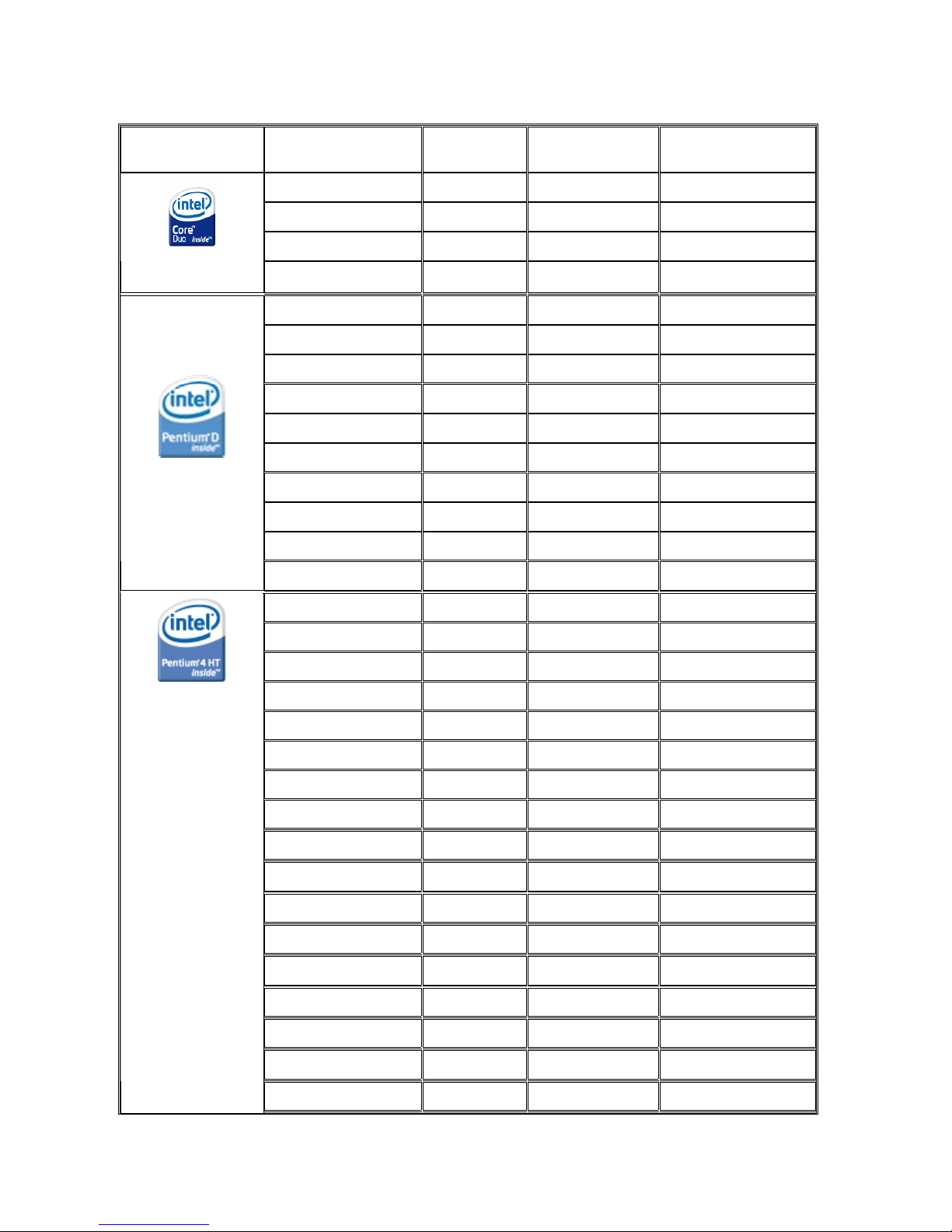
Supported CPU List in Detail
See the table below for a complete list of supported processors.
Processor Family Processor Number
Processor
Speed
System Bus
Frequency
L2 Cache Size
E6700 2.66 GHz 1066 MHz 4 MB
E6600 2.40 GHz 1066 MHz 4 MB
E6400 2.13 GHz 1066 MHz 2 MB
Intel® Core™2
Duo
E6300 1.86 GHz 1066 MHz 2 MB
960 3.60 GHz 800 MHz 2x2 MB
950 3.40 GHz 800 MHz 2x2 MB
945 3.40 GHz 800 MHz 2x2 MB
940 3.20 GHz 800 MHz 2x2 MB
930 3 GHz 800 MHz 2x2 MB
925 3 GHz 800 MHz 2x2 MB
920 2.80 GHz 800 MHz 2x2 MB
915 2.80 GHz 800 MHz 2x2 MB
820 2.80 GHz 800 MHz 2x1 MB
Intel® Pentium® D
805 2.66 GHz 533 MHz 2x1 MB
662 3.60 GHz 800 MHz 2 MB
661 3.60 GHz 800 MHz 2 MB
651 3.40 GHz 800 MHz 2 MB
650 3.40 GHz 800 MHz 2 MB
641 3.20 GHz 800 MHz 2 MB
640 3.20 GHz 800 MHz 2 MB
631 3 GHz 800 MHz 2 MB
630 3 GHz 800 MHz 2 MB
620 2.80 GHz 800 MHz 2 MB
551 3.40 GHz 800 MHz 1 MB
550J 3.40 GHz 800 MHz 1 MB
550 3.40 GHz 800 MHz 1 MB
541 3.20 GHz 800 MHz 1 MB
540J 3.20 GHz 800 MHz 1 MB
540 3.20 GHz 800 MHz 1 MB
531 3 GHz 800 MHz 1 MB
Intel® Pentium® 4
530J 3 GHz 800 MHz 1 MB
Viglen Ltd. PMPGS001
-4-
Page 5

530 3 GHz 800 MHz 1 MB
521 2.80 GHz 800 MHz 1 MB
520J 2.80 GHz 800 MHz 1 MB
520 2.80 GHz 800 MHz 1 MB
524 3.20 GHz 533 MHz 1 MB
360 3.46 GHz 533 MHz 512 KB
356 3.33 GHz 533 MHz 512 KB
355 3.33 GHz 533 MHz 256 KB
352 3.20 GHz 533 MHz 512 KB
347 3.06 GHz 533 MHz 256 KB
350 3.20 GHz 533 MHz 256 KB
346 3.06 GHz 533 MHz 256 KB
345J 3.06 GHz 533 MHz 256 KB
341 2.93 GHz 533 MHz 256 KB
340J 2.93 GHz 533 MHz 256 KB
336 2.80 GHz 533 MHz 256 KB
335
2.80 GHz 533 MHz 256 KB
330-331 2.66 GHz 533 MHz 256 KB
325-326 2.53 GHz 533 MHz 256 KB
Intel® Celeron® D
320 2.40 GHz 533 MHz 256 KB
Viglen Ltd. PMPGS001
-5-
Page 6

• System Board Components
Figure 1 - Motherboard Layout & Components
Table 1
Item Description Item Description
A Front panel audio header P Front chassis fan header
B PCI Conventional bus add-in card
connector 1
Q Chassis intrusion h eader
C PCI Express x1 connector R Intel 82801HO I/O Controller Hub
(ICH8DO)
D Back panel connectors S BIOS Setup configuration jumper block
E Processor core power connector T Auxiliary front panel power LED header
F Rear chassis fan header U Front panel header
G LGA775 processor socket V Serial ATA connectors [4]
H Intel 82Q963 GMCH W Front panel USB header
I Processor fan header X Speaker
J DIMM Channel A sockets Y Front panel USB header
K Serial port header Z Parallel ATE IDE connector
L DIMM Channel B socket s AA PCI Conventional bus add-in card
connector 2
M Diskette drive connector BB High Definition Audio header
N Main Power connector - O Battery - -
Viglen Ltd. PMPGS001
-6-
Page 7

• Back Panel Connectors 5.1 SigmaTel audio STAC9227
The Motherboard external IO connectors are attached to a metallic I/O shield. This shield
serves several purposes:
• It protects the sensitive Motherboard from any external EMC interference.
• It stops the computer from interfering with other electrical devices.
• It allows the Motherboard to be easily upgraded in the future without having to resort to
buying a whole new case. Simply change the I/O shield to match the Motherboard.
The I/O shield provides external access to onboard VGA port, Parallel Port, six USB
connectors as well as one LAN Port and audio connectors.
Figure 2 - Back Panel Connectors
Table 2
Item Description Item Description
A PS/2 Mouse Port F LAN (RJ45)
B PS/2 Keyboard Port G USB 2.0 ports (2)
C Parallel port (Burgundy) H
Audio line in/Retasking Jack
[Blue]
D VGA port (blue) I
Line out/retasking jack
[Green]
E USB 2.0 ports (4) J
Mic in/retasking jack
[Pink]
- -
Viglen Ltd. PMPGS001
-7-
Page 8

• Internal headers
There are connector headers on the motherboard for Front Panel, Alternative front panel
Power LED, USB1/USB2, HD Audio Link, Audio and Serial connector headers. The location
and or details of these internal headers are shown below (Figure 3).
Figure 3 - Internal Headers
Table 3
Item Description
A Front Panel connectors
B Alternative Front Panel Power LED
C USB1/USB2
D Intel HD Audio Link
E Audio (HD/AC’97)
F Serial Connector
Viglen Ltd. PMPGS001
-8-
Page 9

• Front Panel connections
The following are all connectors situated along the front edge of the motherboard. They are
often connected to buttons and LED’s situated on the front panel.
Figure 4 – Front Panel Connectors
Table 4
Pin Connector Comments
1-3 HD LED This goes to the Hard Disk L.E.D. on the front
panel, which lights up when the SATA Hard Disk
is in use.
2-4 Power LED This attaches to the power L.E.D on the front
panel, to display if the computer is active or not.
5-7 Reset switch
connector
When these pins are shorted, it will cause the
computer to perform a cold reboot.
6-8 Power On/Off When these pins are shorted it turns the
computer on and off.
Viglen Ltd. PMPGS001
-9-
Page 10

• Memory
The board has four DIMM sockets and supports the following memory features:
• 1.8 V (only) DDR2 SDRAM DIMMs with gold-plated contacts
• Unbuffered, single-sided or double-sided DIMMs with the following restriction:
Double-sided DIMMS with x16 organization are not supported.
• 8 GB maximum total system memory using DDR2 667 or DDR2 533 DIMMs;
• Minimum total system memory: 512 MB
• Non-ECC DIMMs
• Serial Presence Detect
• DDR2 533 and DDR2 667 MHz SDRAM DIMMs
NOTE: A minimum of 512 MB of system memory is required to fully enable
both the onboard graphics and the manageability engine.
NOTE: To be fully compliant with all applicable DDR SDRAM memory specifications, the
board should be populated with DIMMs that support the Serial Presence Detect (SPD) data
structure. This enables the BIOS to read the SPD data and program the chipset to accurately
configure memory settings for optimum performance. If non-SPD mem ory is installed, the
BIOS will attempt to correctly configure the memory settings, but performance and reliability
may be impacted or the DIMMs may not function under the determined frequency. Table 5 lists the supported DIMM configurations
.
Table 5. Supported Memory Configuration
DIMM
Type
SDRAM
Technology
Smallest
usable
DIMM (one x16
Single-sided
DIMM)
Largest usable
DIMM (one x8
Double-sided
DIMM)
Maximum
capacity
with four
identical
x8 Doublesided
DIMMs
DDR2 533 256 Mbit 128 MB 512 MB 2 GB
DDR2 533 512 Mbit 256 MB 1 GB 4 GB
DDR2 533 1 Gbit 512 MB 2 GB 8 GB
DDR2 667 256 Mbit 128 MB 512 MB 2 GB
DDR2 667 512 Mbit 256 MB 1 GB 4 GB
DDR2 667 1 Gbit 512 MB 2 GB 8 GB
NOTE: Regardless of the DIMM type used, the memory frequency will either be equal to or
less than the processor system bus frequency. For example, if DDR2 667 memories is used
with a 533 MHz system bus frequency processor, the memory will operate at 533 MHz. Table
6 lists the resulting operating memory frequencies based on the combination of DIMMs and
processors.
Table 6- Operating Memory Frequencies
DIMM Type Processor system bus
frequency
Resulting memory
frequency
DDR2 533 533 MHz 533 MHz
DDR2 533 800 MHz 533 MHz
DDR2 533 1066 MHz 533 MHz
DDR2 667 533 MHz 533 MHz
DDR2 667 800 MHz 667 MHz
DDR2 667 1066 MHz 667 MHz
Viglen Ltd. PMPGS001
-10-
Page 11

Initial BIOS Release.
MQ96510J.86A.1577.2006.1115.2315 (VERSION: 1577)
Driver’s initial release
Windows 98SE, Windows ME, Windows NT4 are not supported
Windows 2000 & Windows XP Drivers
Audio: Sigmatel STAC9227 5.10.5208 11.2MB 08/11/2006
INF: Intel® Chipset Software Installation Utility 8.1.1.1010 665KB 08/12/2006
LAN: Intel® PRO Network Connections
(Intel® 82566DC Gigabit Ethernet Controller)
11.2 86.2MB 19/10/2006
Intel Management Engine AFSC 2.1.22.1026 916KB 11/7/2006
Graphics: Intel Graphics (Intel® GMA 3000) 14.25.4704 11.5MB 09/10/2006
Windows XP Professional x64 Edition Drivers
Audio: Sigmatel STAC9227 5.10.5208 12MB 08/11/2006
INF: Intel® Chipset Software Installation Utility 8.1.1.1010 665KB 08/12/2006
LAN: Intel® PRO Network Connections
(Intel® 82566DC Gigabit Ethernet Controller)
11.2 86.2MB 19/10/2006
IntelManagement Engine AFSC 2.1.22.1026 916KB 11/7/2006
Graphics: Intel Graphics (Intel® GMA 3000) 14.25.64.4704 11.5MB 15/10/2006
Windows XP64 Audio driver Hot fix:
IMPORTANT: Audio drivers may fail to install in Windows* XP 64-Bit Edition. Symptoms may
include error messages, such as "Error in installation" or "Unknown error". Microsoft's Update
for Windows XP x64 Edition (KB901105) fixes this issue. After installing this update, the audio
drivers for Windows XP 64-Bit Edition will successfully install.
(
http://support.microsoft.com/default.aspx?scid=kb;en-us;901105)
WindowsServer2003.WindowsXPKB901105-v3-x64-ENU.exe
KB901105 734KB
-
NDSIS2
Intel(R) PRO/1000 Gigabit Ethernet
Connection Driver
4.96 1.61MB -
Note: All the above drivers are PC99 certified.
Other Drivers and Patches
Patch-USBBIOSx (Registry Patch for
Windows XP Pro & Windows Home for wakeup under S3 via USB mouse/Keyboard)
- 260 KB 06 Sept 2006
DOS CDROM Support Driver Instruction
(SBIDE.SYS)
- 614 KB 15 April 1997
Viglen Ltd. PMPGS001
-11-
Page 12

Drivers Installation Instruction
When carrying out fresh installation of operating systems it is recommended device drivers be
installed in following order.
1. Chipset (Intel® Chipset Software Installation Utility)
2. Intel Manage ment Engine AFSC
3. Display (Intel Grap hics (Intel® GMA 3000)
4. Audio (Sigmatel STAC9227)
5. LAN (Intel® PRO Network Connections)
Viglen Ltd. PMPGS001
-12-
 Loading...