

Page 1

Model 3100C
Service Manual
The circuit schematics herein provided for reference only are not necessarily the latest version.
Mainboard 77-31C00-D04A
Switch Board 77-31B0S-D01
LED Board 77-31B04-D01
D/D Board 77-31C00-D04A Mainboard 31 to 33
Power Board 71-31B0E-D05
Specifications are subject to change without notice. May. 2000
Page 2

3100 C
Specifications ................................................................................................................................. 1
Processor Module................................................................................................................... 1
Memory.................................................................................................................................. 1
System BIOS.......................................................................................................................... 1
Display ................................................................................................................................... 1
Mass Storage.......................................................................................................................... 1
PC Card Socket ..................................................................................................................... 1
Audio ..................................................................................................................................... 2
Input/output ............................................................................................................................ 2
Communication ....................................................................................................................... 2
Power Management ................................................................................................................ 2
AC adapter..................................................................................................................... ........ 2
Rechargeable Battery Pack ..................................................................................................... 2
Size & W eight ......................................................................................................................... 3
Optional.................................................................................................................................. 3
Device Components.......................................................................................................................4
Floppy disk drive ......................................................................................................................... 4
Removable hard disk drive ........................................................................................................... 4
Keyboard.................................................................................................................................... 4
LCD display module .................................................................................................................... 5
Maps........................................................................................................................................... 6
Motherboard ............................................................................................................................... 7
Microprocessor ...................................................................................................................... 7
Northbridge Chip – INTEL 82443BX Host Bridge Controller ................................................. 7
Southbridge Chip - INTEL 82371EB (PIIX4E)....................................................................... 7
VGA controller – A TI 3D RAGE LT PRO .............................................................................. 8
PC CARD 95 (CARD BUS) interface controller - TI-1225..................................................... 8
ZV Port Custom Interface ....................................................................................................... 9
Super I/O Floppy disk Controller – FDC37N869 ................................................................... 9
High Performance PCI Audio Chip – ES1978S....................................................................... 9
Audio CODEC ES1918 ....................................................................................................... 10
Keyboard controller - M38867M8 ....................................................................................... 10
Battery Information ..................................................................................................................... 11
Power loss................................................................................................................................. 11
Battery storage .......................................................................................................................... 11
Outside the computer ............................................................................................................ 11
Inside the computer ............................................................................................................... 11
Battery Testing ........................................................................................................................... 11
Battery alarm ............................................................................................................................. 12
Device port connectors and Pin assignments ............................................................................. 13
Floppy Disk Drive & Secondary Hard Disk Drive Interface ........................................................ 13
Hard Disk Drive Interface .......................................................................................................... 14
Secondary Master CD-ROM Drive Interface............................................................................. 14
RS-232C Serial Interface........................................................................................................... 15
Page 3

Parallel Interface ........................................................................................................................ 15
Expansion Memory Socket ........................................................................................................ 16
Port Replicator connector pin assignment.................................................................................... 18
Internal trackpad Interface ......................................................................................................... 19
External Monitor Interface.......................................................................................................... 19
External TV-out Interface........................................................................................................... 19
External Keyboard/PS2 Mouse Interface ................................................................................... 20
PCMCIA CardBus Interface ..................................................................................................... 21
Socket A: ............................................................................................................................. 21
Socket B:.............................................................................................................................. 22
Internal PCI Interface (For optional modem or LAN card) ......................................................... 23
LCD Interface ( For XGA TFT) ................................................................................................ 24
DC/DC Converter Board ............................................................................................................ 24
Input Characteristics .................................................................................................................. 24
Efficiency ................................................................................................................................... 24
Output Characteristics................................................................................................................ 24
Inverter Board ............................................................................................................................. 25
Pin Assignment .......................................................................................................................... 25
Connector 1; Input Connector............................................................................................... 25
Connector 2; Output Connector ............................................................................................ 25
Electrical Specifications ......................................................................................................... 25
System Resource Allocation (In Windows 98) ........................................................................... 26
IRQ: .......................................................................................................................................... 26
DMA:........................................................................................................................................ 26
Installation Procedures................................................................................................................ 27
Installing/Upgrading a processor ................................................................................................ 27
Removing the heat sink.......................................................................................................... 28
Remove the existing processor............................................................................................... 29
Replace the HEX STUDS ( if you are installing a PPGA-370 type processor) ........................ 31
Install a new processor.......................................................................................................... 32
Install the heat sink ................................................................................................................ 34
Updating the Flash ROM BIOS ................................................................................................. 35
A: Download the BIOS update from the website................................................................... 35
B: Create a bootable Floppy Disk. ....................................................................................... 35
C: Copy your BIOS files onto the bootable Floppy Disk....................................................... 35
D: Set the DIP switches to ON............................................................................................. 36
E: Reboot your computer from the FDD ............................................................................... 36
F: Set the DIP switches to the OFF position ......................................................................... 37
G: Reboot your computer from the HDD .............................................................................. 37
Page 4

1
Specifications
The Model 3100C is a powerful Intel Pentium !!! processor based Notebook PC, which can also
use Intel Celeron Processors. The main unit is designed to support 600 Mhz and higher should you
need a faster processor in the future.
Processor Module
- Intel® Pentium !!! (FC-PGA 370) 500, 550 and 600 MHz processor with 256KB integrated
full speed L2 cache packaged in a 370 pin PGA socket.
- Intel® Celeron (PPGA 370) 300A, 333, 360, 400 and 430 Mhz with 128 KB integrated full
speed L2 cache packaged in a 370 pin PGA socket.
Memory
- Provides 64-bit data bus system memory
- T wo 144 pin SODIMM sockets, supports 3.3V, PC-100 compliant, Sync DRAM SODIMM
- Expandable memory up to 256 MB, depends on 32 / 64/ 128 MB SODIMM Module
System BIOS
- One 256KB Flash ROM
- Insyde BIOS with Smart Battery
- Plug and Play 1.0a
- ACPI 1.0
Display
- XGA TFT flat panel 13.3" / 14.1" LCD screen
- AGP 2X
- Complete 64 bit hardware 2D / 3D Accelerator Graphics Engine
- Motion Compensation
- High quality TV-out (6 Line buffer quality) with MacroV ision® V7.01 anti-copy technology
- 8MB display memory SGRAM type (100MHz)
- V ertically Interpolate 720V x 480H pixel wide video source
- Supports TFT panel resolution up to 1024x768x16M
- CRT resolution up to 1280x1024x16M (non-interlaced)
- TV resolution 1024x768
- Tri-view for triple display devices: TV, CR T and LCD
- DuoView display capability under W indows 98
- Supports Zoomed Video Port
- Supports Software MPEG II
Mass Storage
- One removable intelligent bay for 3.5" 3-mode FDD / 12.7mm(h) LS-120/2.5" 12.7mm(h) 2nd
HDD
- One easy change bay for DVD-ROM(12.7mm) / CD-ROM (24X speed or higher)
- Removable 2.5" 12.7mm (h) or 9.5mm (h) HDD, supports LBA mode
- Supports DMA mode 2/ PIO mode 4/ ATA-33 (Ultra DMA) IDE
PC Card Socket
- T wo (PCI) PCMCIA 3.3V/5V sockets , 2 type II or 1 type III
Page 5

2
- Supports Zoom Video Port (Socket A)
- Supports CardBus (PC Card95)
Audio
- 3D stereo enhancement sound system
- Full duplex support
- Compatible with Sound-Blaster PRO version 3.01
- Built in microphone
- 2 built in speakers
- Hardware W avetable
Input/output
- Built in Trackpad (PS/2)
- Dual USB ports
- One serial port
- One parallel port (LPT1)
- One Infrared (FIR) file transfer
- One external CRT monitor
- One S-Video jack for TV output
- One External keyboard / Mouse (PS/2 type) port
- One line-in jack
- One headphone jack
- One microphone jack
- One RJ-11 jack for 56K S/W Modem (optional) or one RJ-45 jack for
10M/ 100M LAN Module (optional)
- One (120 pins) connector for Port Replicator
- DC-in jack
Communication
- Wireless Infrared: 4M bps data rate/ 1cm ~1M operating distance, and compliant with IrDA 1.
1 or ASKIR (SHARP standard)
Power Management
- Supports ACPI v1.0
- Supports APM v1.2
- CPU Over T emperature Protection
- Device Power Management for all devices
- Supports suspend to disk (APCI mode excluded)
- Battery low suspend
- Resume from alarm time/modem ring (Com Port only)
AC adapter
- Full Range AC adapter - AC in 100~240V,47~63Hz.
Rechargeable Battery Pack
- Supports one pack removable Smart Lithium-Ion Battery or Dumb Ni-MH Battery
Page 6

3
Size & Weight
- 316 mm (w) x 256 mm (d) x 38.5 mm (h)
- 3 kg with Li-Ion battery
Optional
- 3001S Lithium-Ion smart battery pack
- 3002D Ni-MH battery pack
- 2005 Car Adapter
- 3006 Port Replicator
- 3007 LS-120 120 MB Floppy Drive Kit
- 1008A S/W MPEG II
- 3009 56K Modem Module (V.90 Compliant)
- 300D DVD-ROM Drive Kit
- 300F 10M/ 100M LAN Module
Page 7

4
Device Components
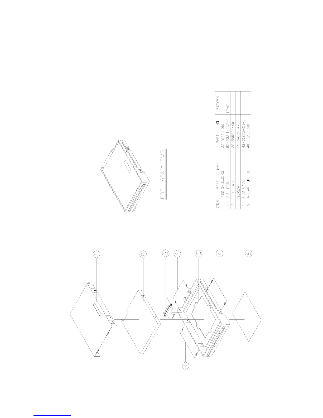
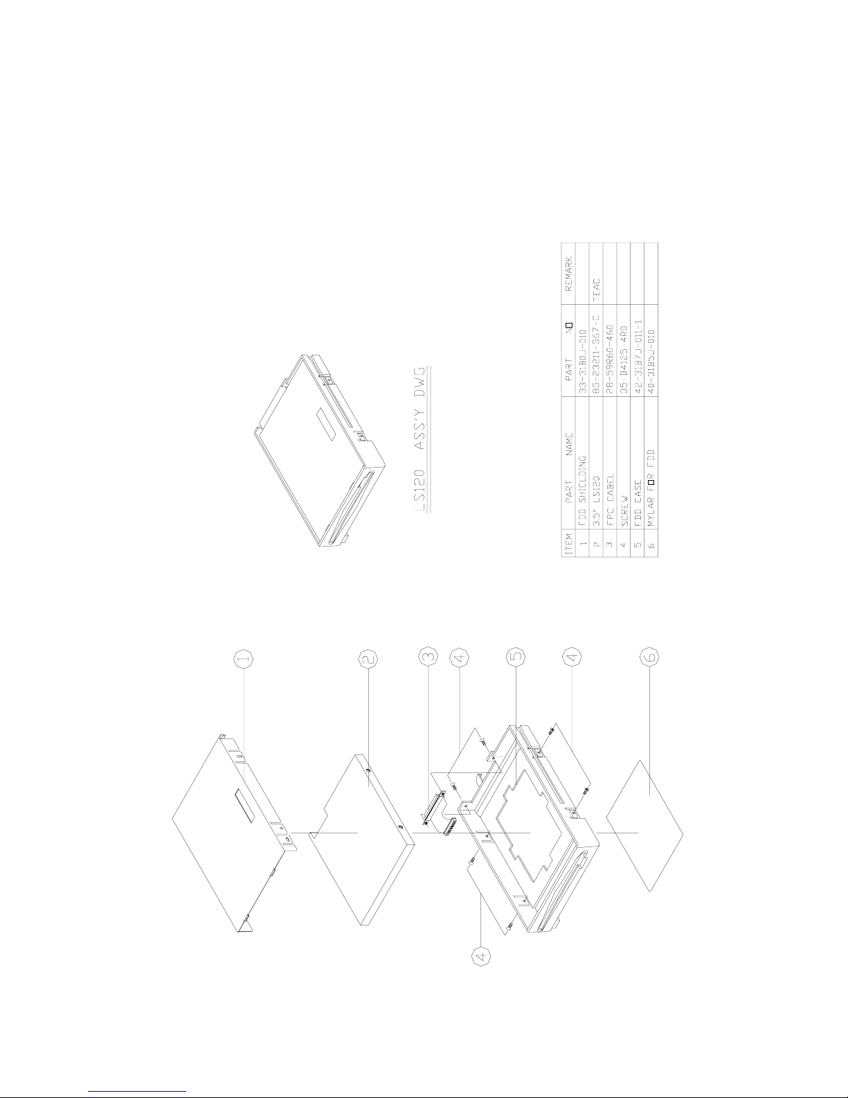
Floppy disk drive
The Model 3100C Notebook PC includes 3.5" removable 1.44MB floppy disk drive.
A. Specifications :
••
••
• Media: 3.5" floppy diskette, double side, high density, 135 TPI
••
••
• Storage capacity: 1.44MB (formatted) per drive, 18 sectors/track, and 512 bytes/sector.
••
••
• Track to track seeks time: 3ms
••
••
• Recording density: 2 heads, 160 tracks
••
••
• Data transfer rate: 500K bits/sec (MFM)
••
••
• Disk rotation speed: 300 rpm (typ.)
••
••
• A verage track access time: 17ms
B. Qualified vendors:
••
••
• PANASONIC JU-227AF
••
••
• TEAC FD-04HF-1300
Removable hard disk drive
The Model 3100C Notebook PC has an internal mountable 2.5" hard disk drive. It is specially
shock-mounted for durability and reliability in a portable environment.
A: Specifications:
••
••
• Storage capacity: 2.0 GB
••
••
• Host transfer rate (PIO mode): 16.6 MB/s
••
••
• Ultra DMA A T A-33: 33MB/S
••
••
• A T A-2/A T A-3 interface support
••
••
• A verage seeks time: 13 ms (average)
••
••
• A verage latency: 7.14 ms
••
••
• Interleave: 1:1
B. Qualified vendors:
• TOSHIBA MK6409MAV 6.4GB
• HIT ACHI DK228A65 6.5GB
• FUJITSU MHE2064A T 6.4GB
• IBM DTDA-26480 6.4GB
Keyboard
The Model 3100C Notebook PC can use a 87, 88 or 89-key keyboard that is compatible with
an IBM PC/AT keyboard.
Keyboard features:
- Full-sized keys and standard spacing between keys
- Embedded numeric keypad with dedicated alteration keys
- Cursor control keys: Left, Right, Up, Down
- Screen control keys: Insert, Delete, Home, End, PgDn, PgUp
- 12 function keys
- Function support for NumLock, CapsLock, ScrollLock
Page 8

5
The keyboard uses membrane key-switches with the following features:
- Contact type : Membrane
- T otal travel : 3.0-mm ±0.3 mm
- Operating point : End on
- T ouch feeling : Soft tactile
- Click sound : Sileat tactile
- Operating lifetime : 5 million cycles
- Operating forces : 57 ± 15g
The keycaps specifications are:
- Material used : ABS
- Legends : Printed with coating
- Operating lifetime of Legends : 5 million cycles
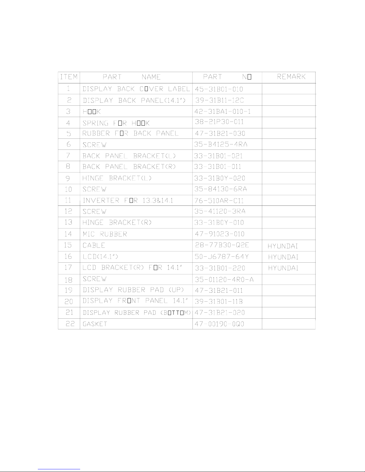
LCD display module
The Model 3100C Notebook PC has a full range of TFT color LCD display modules with
different Clevo internal designed inverters. These display modules can be tilted up for easy viewing of
data display. The selected module will be a dot-matrix color LCD unit with the following features:
- Resolution: XGA 1024X768 pixels
- Interface : LVDS
- Backlight : side edged CCFT
Qualified LCD modules:
• 14.1" TFT color : HYUNDAI HT14X12-101
• 14.1" TFT color : HYUNDAI HT14X11-101
• 14.1" TFT color : LG LP141XA-A1NA
• 13.3" TFT color : HYUNDAI HT13X13-203
• 13.3" TFT color : HYUNDAI HT13X14-101
• 13.3" TFT color : LG LP141XA-A1
• 13.3" TFT color : LG LP133X4
Page 9
6
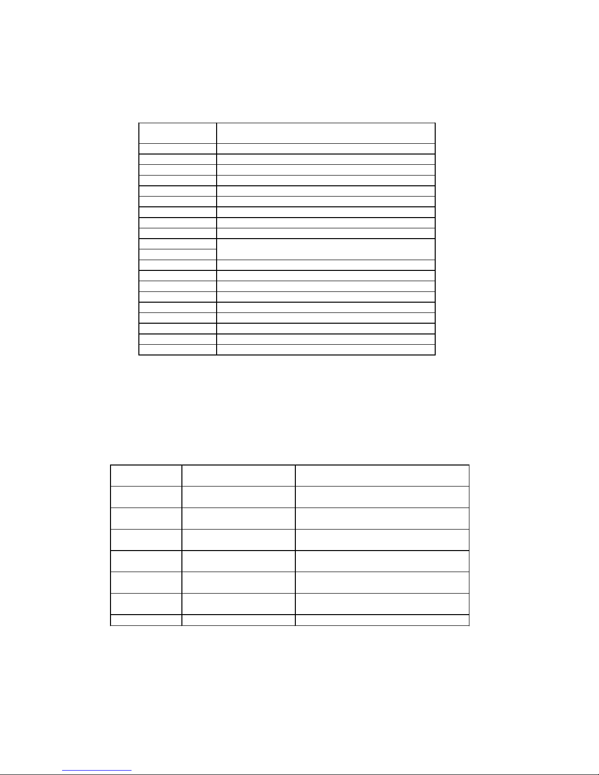
ADDRESS SIZE FUNCTION
000000 09FFFF
640KB 640KB Base Memory
0A0000 0BFFFF
128KB Video RAM
0C0000 0CFFFF
64KB VGA BIOS
0D0000 0DFFFF
64KB Reserved
0E0000 0EFFFF
64KB System BIOS for SCU,
PCI, PnP, PMU
0F0000 0FFFFF
64KB System BIOS for Kernal
100000 - 16MB to 256MB Extended Memory
System Memory Map
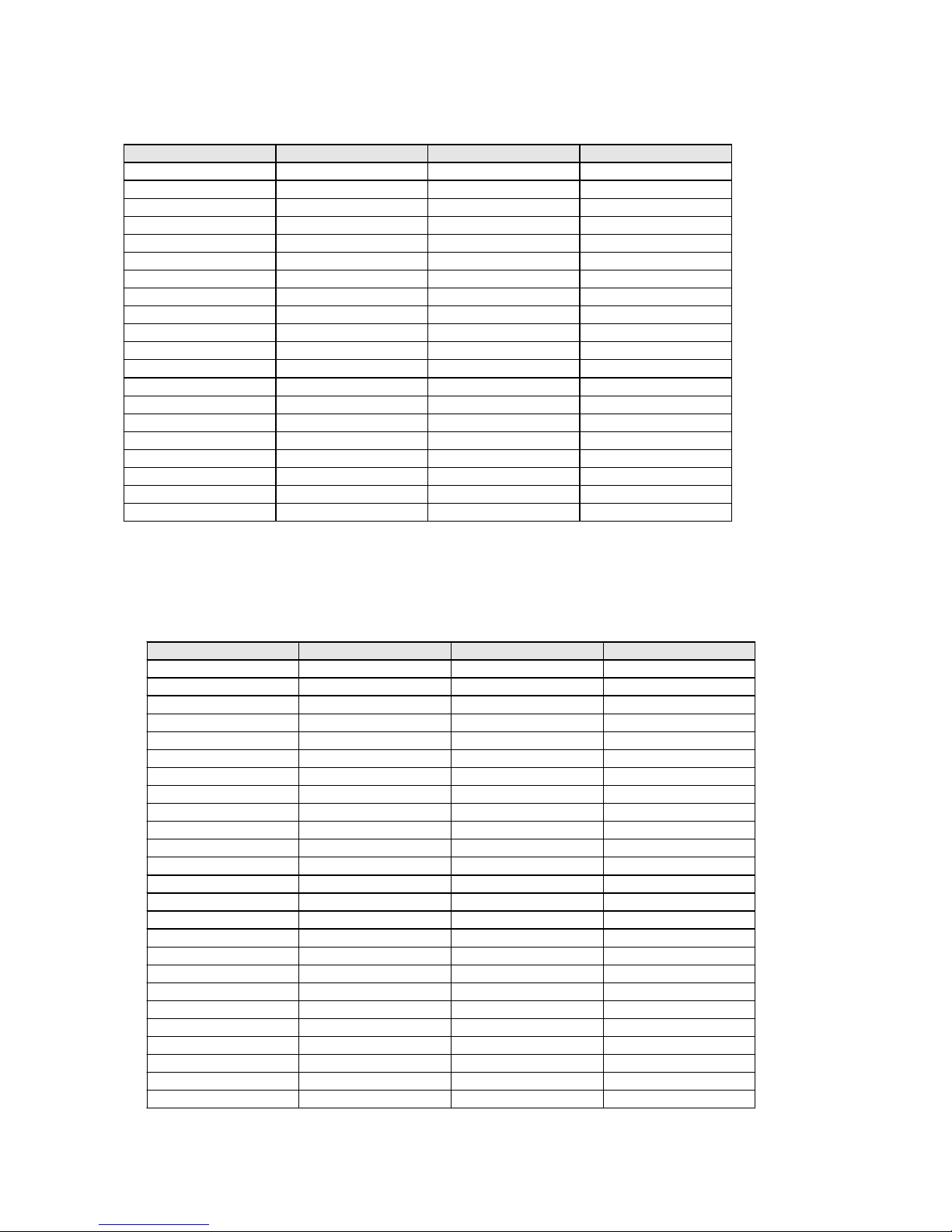
Hex range Device
000 - 00F DMA controller-1
020 - 021 Interrupt controller-1
040 - 043 Timer 1
048 - 04B Timer 2
060 - 06E KB controller M38813 chi
p
070 - 071 RTC and NMI mask
080 - 08F DMA page register
0A0 - 0A1 Interrupt controller-2
0C0 - 0DF DMA controller-2
1F0 - 1F7 Fixed disk select
3F6 , 3F7
2F8 - 2FF Serial port 2
378 - 37A Parallel port 1
3B4 , 3B5 CRT controller index (mono
)
3D4 , 3D5 CRT controller index (color
)
3BA Feature control
3C0 - 3DA
3F2 - 3F7 Flo
ppy
disk controller
3F0 , 3F1 Configuration port
3F8 - 3FF Serial port 1
Maps
I/O Address Map
Page 10

7
Motherboard
The motherboard is designed to accept Intel Celeron/Pentium III processors and includes the
following Chipset function:
- Microprocessor
- 440BX chipset solution from INTEL
- A TI 3D RAGE L T PRO Multimedia Flat Panel Controller
- TI 1225 PC CARD Controller
- FDC37N869 super I/O Controller
- ES1978s PCI Audio Chip and ES1918 AC97’s CODEC
- M38867 Keyboard Controller
Microprocessor
The 3100C Notebook supports the following processors:
A : Intel Celeron 300A/333/366/400/433
B : Intel Pentium !!! 500/550/600 Microprocessor
.
Features:
- Performance improved over existing mobile processors
- Integrated primary (L1) 16Kbyte instruction and data caches
- Integrated second level (L2)128Kbyte cache for Celeron family
256Kbyte cache for Pentium III family
- Low Power GTL+ system bus interface
- Enhanced 64 bits data bus
- Data integrity features
- SL technology power management features
- Multiprocessing support
- Performance monitoring
- Memory page size feature
Northbridge Chip – INTEL 82443BX Host Bridge Controller
The Intel 443BX AGPset is intended for the Pentium II processor platform and emerging 3D
graphics/multimedia applications. Host Bridge provides a Host-to-PCI bridge, optimized DRAM
controller and data path, and an Accelerated Graphic Port (AGP) interface. AGP is a high
performance, component level interconnect targeted at 3D graphics applications and is based on set of
performance enhancements to PCI.
- Processor/Host Interface
- Memory Interface
- PCI bus Interface
- AGP Interface
- Power Management Functions (Only 440BX)
Southbridge Chip - INTEL 82371EB (PIIX4E)
It contains the following features:
- Supported Kits for both Pentium family Microprocessors
- Multifunction PCI to ISA Bridge
Page 11

8
- Supports PCI at 33 MHz
- Supports PCI Rev 2.1 Specification
- Supports Full ISA or Extended I/O bus
- Supports Mobile Deep Green Environments
- 3.3V Operation with 5V T olerant Buffers
- Ultra-low Power for Mobile Environments Support
- Full Support for APCI (Advanced Configuration and Power Interface) Revision 1.0
- Integrated IDE Controller
- Supports Ultra DMA/33
- Supports two 82C37 Enhanced DMA Controller
- Supports two 82C59 Interrupt Controller
- Supports 82C54 Timer Based
- Supports UHCI USB Ports
- Supports SMBus
VGA controller – A TI 3D RAGE LT PRO
The A TI 3D RAGE L T PRO Multimedia Flat Panel Controller is a DRAM based, fully integrated
LCD, CR T & TV 64 bits controller for AGP systems. It contains the following functions:
- Supports displays for 8 MB
- 64bit high performance 2D/3D Graphic Engine
- Supports bus master AGP and SGRAM memory
- Supports 24 bit TFT panels up to 1024x768 resolution
- Supports non-interlaced 1280x1024x64k, 1024x768x16M, 800x600x16M, and
640x480x16M color on CRT
- Simultaneous display in 24 bit color on flat panel and CR T
- Internal buffer provides flicker reduction
- A TI 3D RAGE LT PRO DAC can directly interface with a standard off-the-shelf NTSC/P AL
encoder. Composite synchronization signals support for standard home TV connection up to
1280x1024x16M and 16:9 Wide mode
- Graphic functions optimized by a 64-bit internal data bus and VGA, SVGA, and XGA flat
panel
- Provides flexible and extensive power management capabilities and supports four states of
VESA Display Power Management Signaling standard
- Industry leading DuoView Simultaneous display at W indows 98
- Fully compliant ZV-port interface with device driver support for VPM
- Motion compensation
PC CARD 95 (CARD BUS) interface controller - TI-1225
TI Card bus Interface Controller 1225 implements the PCMCIA 2.0/JEIDA 4.1 standard. It
contains the following functions:
- Supports 2 PCMCIA 2.1& JEIDA 4.2 R2 cards or 2 CardBus cards
- Y enta Registers-compatible
- Supports Zoom Video Mode
- PCMCIA dual-socket interface
- One-Slot plus MPEG three Zoomed Video Ports support
Page 12

9
- Bus Master Transfer capability
- Supports both 5V and 3.3V PC cards
- Support PCMCIA_A T A Specification
- Supports Advanced Submicron Low Power CMOS T echnology
- Supports ACPI 1.0 Compliant
- 208 pin TQFP package
ZV Port Custom Interface
The ZV (Zoomed V ideo) Port is a single source, point-to-point unidirectional video bus between
a PC Card socket and a VGA controller. The ZV Port complies with CCIR601 timing to allow NTSC
decoders to deliver real-time digital video straight into the VGA frame buffer from a PC Card. The ZV
Port also allows an industry standard mechanism for transferring digital audio PCM data to a low cost
DAC for conversion to an analog signal.
Super I/O Floppy disk Controller – FDC37N869
The SMC FDC37N869 super I/O is optimized for motherboard applications. It provides:
- Intelligent Auto Power Management
- 16 Bit Address Qualification
- 1.44MB Super I/O Floppy Disk Controller
••
••
• Support Vertical Recording Format
••
••
• 16 Byte Data FIFO
••
••
• 48 Base I/O Address, 15 IRQ and 4 DMA options
- Enhanced Digital Data Separator. Data rate up to 1Mbps.
- Multi-Mode Parallel Port with ChiProtect Circuitry
••
••
• Standard Mode
IBM PC/A T and PS/2 compatible Bidirectional Parallel port.
••
••
• Enhanced Mode
Enhanced Parallel Port (EPP) Compatible
••
••
• High Speed Mode
Microsoft and Hewlett Packard Extended Capabilities Port (ECP) Compatible
- Serial Port
••
••
• T wo high speed NS16C550 compatible UAR T s with Send/Receive 16 Byte FIFOs
••
••
• Programmable Baud Rate Generator
••
••
• Modem Control Circuitry
••
••
• Infrared-IrDA1.2(4Mbps), HPSIR, ASKIR, Consumer IR Support
High Performance PCI Audio Chip – ES1978S
- 500-MIPS-equivalent dual –engine PCI audio accelerator
- HRTF 3D positional audio accelerator
- 64-Channel wavetable synthesis
••
••
• Advanced platform for interactive 3-D gaming, DVD movie
••
••
• playback, and internet communications
- Full plug and play
••
••
• Multi-Stream Directsound and Directsound 3D
••
••
• Advanced platform for interactive 3D game and DVD movie playback
Page 13

10
••
••
• Full DOS game compatibility
••
••
• I2S Zoomed Video interface
Audio CODEC ES1918
-Single, high-performance, mixed-signal, 16-bit stereo VLSI chip
- Meet Audio Codec ‘97 analog performance specification
- Full-duplex operation for simultaneous record and playback
••
••
• 8-channel record source with stereo inputs for line , CD audio, video audio, auxiliary line,
playback mix, and mono inputs for microphone, phone and mono playback mix.
••
••
• 8-channel playback mixer with stereo inputs for line, CD audio ,video audio, auxiliary line,
digital audio (wave files), and mono inputs for microphone, phone and PC beep.
••
••
• Mixer-controlled record and playback with programmable 5-bit (32 step) logarithmic
master volume control.
Keyboard controller - M38867M8
- Memory size: 1024 bytes (RAM)
- Timers: 8 bit pre-scaler X 4 + 8 bit timer X 3
- Comparator: 4 bit X 8 channels
- Bus interface: 2 bytes
- Key on wake-up: 8 channels
- Interrupts: 8 external, 7 internal and 1 software
- A-D converter: 8 channels
- D-A converter: 2 channels
- PWM: 2 channels
- System bus interface: 8042 type
Page 14

11
Battery Information
Proper care will improve the performance and extend the life and cycle life of your battery. Please
follow these simple guidelines to get the best use out of your battery.
Power loss
When not in use, a battery will gradually lose its power, this is normal. The rate of power loss
depends on the battery type and is approximately:
2% / Day for a Ni-MH Battery
0.2% / Day for a Li-Ion Battery
Battery storage
Outside the computer
If you are going to store a battery outside your computer for an extended period you must:
· Charge the battery to at least 40% capacity prior to storage.
· Follow steps 1 through 3 approximately every 30 days:
1. Completely recharge the battery.
2. Use the battery until it is fully discharged
3. Recharge the battery to at least 40% capacity.
Inside the computer
If a fully charged battery is stored inside the computer and the battery is not used for more
than 30 days, you must follow these steps:
1. Completely recharge the battery.
2. Use the battery until it is fully discharged
3. Recharge the battery to 100% capacity.
(In this case it doesn’t matter whether or not the computer is being used)
Note: An empty battery will become damaged if stored too long and by following these
steps the battery cycle life and the battery life will increase.
Battery Testing
T esting a battery while its temperature remains high could possibly cause inaccurate
measurements, therefore we strongly recommend:
· W aiting 30 minutes before testing a battery that has just been fully charged.
· W aiting at least 30 minutes before recharging a fully discharged battery .
Note: All battery testing should be done on a fully charged or fully discharged battery.
Page 15

12
Battery alarm
The battery alarm is activated by a program and will sound when the battery power is low.
Note: If a fully discharged battery has been charged for less than 3 minutes, this program will
not be activated.
This happens when these 3 steps occur:
1. The computer is being used and the low battery alarm sounds.
2. The AC adapter is connected to charge the battery while the computer continues to be
used.
3. The adapter is unplugged within the first 3 minutes of charging.
After this sequence of steps, the computer will eventually shutdown without the low battery
alarm sounding and you will lose any work you have entered and not saved.
Therefore you should make sure that the AC adapter is firmly plugged into the computer when
charging the battery.
Page 16

13
Device port connectors and Pin assignments
PIN Description Pin Description
1 FDDVCCS 2 VCCS
3 MTR0# 4 DRV0#
5 3MODE# 6 INDEX#
7 TRK0# 8 DSKCHG#
9 HDSEL# 10 DIR#
11 RDATA# 12 STEP#
13 WP_FD# 14 WDAT#
15 WGATE# 16 NC
17 CDRST# 18 GND
19 DDS7 20 DDS8
21 DDS6 22 DDS9
23 DDS5 24 DDS10
25 DDS4 26 DDS11
27 DDS3 28 DDS12
29 DDS2 30 DDS13
31 DDS1 32 DDS14
33 DDS0 34 DDS15
35 GND 36 GND
37 SDREQ 38 CSEL
39 SDIOW# 40 GND
41 SDIOR# 42 SHD LED
43 SIORDY 44 PDIAG
45 SDACK# 46 SDA2
47 CDIRQ 48 SCS3S#
49 SDA1 50 GND
51 SDA0 52 CD VCC
53 CS1S# 54 CD_VCC
55 GND 56 IRR3
57 IRTX2 58 VCC3S
59 IRRX2 60 VCC3S
Floppy Disk Drive & Secondary Hard Disk Drive Interface
Uses one 60 pin B/B connector with the following configuration:
Page 17
14
Hard Disk Drive Interface
Uses a 40 pin B/B connector with the following configuration
Pin Description Pin Description
1 HDRST# 2 GND
3 DDP7 4 DDP8
5 DDP6 6 DDP9
7 DDP5 8 DDP10
9 DDP4 10 DDP11
11 DDP3 12 DDP12
13 DDP2 14 DDP13
15 DDP1 16 DDP14
17 DDP0 18 DDP15
19 GND 20 PDREQ
21 PDIOW# 22 GND
23 PDIOR# 24 GND
25 PIORDY 26 GND
27 PDACK# 28 PD_CSEL
29 PHDIRQ 30 GND
31 PDA1 32 GND
33 PDA0 34 PDA2
35 PCS1P# 36 PCS3P
37 PHD_LED# 38 HDD_VCC
39 HDD_VCC 40 HDD VCC
Secondary Master CD-ROM Drive Interface
Uses a 50-pin B/B connector with the following configuration:
Pin Description Pin Description
1CD_L2CD_R
3 AGND 4 AGND
5 CDRST# 6 DDS8
7 DDS7 8 DDS9
9 DDS6 10 DDS10
11 DDS5 12 DDS11
13 DDS4 14 DDS12
15 DDS3 16 DDS13
17 DDS2 18 DDS14
19 DDS1 20 DDS15
21 DDS0 22 SDREQ
23 GND 24 SDIOR#
25 SDIOW# 26 GND
27 SIORDY 28 SDACK#
29 CDIRQ 30 NC
31 SDA1 32 PDI AG
33 SDA0 34 SDA2
35 SCS1S# 36 SCS3S#
37 SHD_LED# 38 CD_VCC
39 CD_VCC 40 CD_VCC
41 CD_VCC 42 CD_VCC
43 GND 44 GND
45 GND 46 GND
47 SD_CSEL 48 GND
49 NC 50 NC
Page 18

15
RS-232C Serial Interface
The RS-232C Serial Interface uses a 9 pin D-sub male connector with the following configuration:
Pin
Description
1
DCD (DATA Carrier Detect)
2
RXD (Received Data)
3
TXD (Transmitted Data)
4
DTR (Data Terminal Ready )
5
GND (Signal Ground)
6
DSR (Data Set Ready)
7
RTS (Request To Send)
8
CTS (Clear To Send)
9
RI (Ring Indicator)
Parallel Interface
The Parallel interface uses a 25-pin D-sub female connector with the following configuration:
Pin
Description Pin Description
1
Strobe# 2 data 0
3
Data 1 4 Data 2
5
Data 3 6 Data 4
7
Data 5 8 Data 6
9
Data 7 10 ACK#
11
Busy 12 Paper Empty
13
Select 14 Auto Linefeed#
15
Error# 16 Initialize#
17
Select In 18 Ground
19
Ground 20 Ground
21
Ground 22 Ground
23
Ground 24 Ground
25
Ground
Page 19

16
Expansion Memory Socket
The Model 3100C Notebook PC has two 144-pin SODIMM type memory sockets with the following
configuration:
Pin Descri ption Pin Descri ption Pi n Descript ion Pin Description
1 GND 2 GND 3 MD0 4 MD32
5 MD1 6 MD33 7 MD2 8 MD34
9 MD3 10 MD35 11 VCC 12 VCC
13 MD4 14 MD36 15 MD5 16 MD37
17 MD6 18 MD38 19 MD7 20 MD39
21 GND 22 GND 23 DCAS#0 24 DCAS#4
25 DCAS#1 26 DCAS#5 27 VCC 28 VCC
29 MA0 30 MA3 31 MA1 32 MA4
33 MA2 34 MA5 35 GND 36 GND
37 MD8 38 MD40 39 MD9 40 MD41
41 MD10 42 MD42 43 MD11 44 MD43
45 VCC 46 VCC 47 MD12 48 MD44
49 MD13 50 MD45 51 MD14 52 MD46
53 MD15 54 MD47 55 GND 56 GND
57 NC 58 GND 59 NC 60 NC
61 CLK0 62 CKE0 63 VCC 64 VCC
65 SRAS#0 66 SCAS#0 67 MWE#0 68 CKE1
69 DRAS#0 70 MA14 71 DRAS#1 72 MA12
73 QE# 74 CLK1 75 GND 76 GND
77 NC 78 NC 79 NC 80 NC
81 VCC 82 VCC 83 MD16 84 MD48
85 MD17 86 MD49 87 MD18 88 MD50
89 MD19 90 MD51 91 GND 92 GND
93 MD20 94 MD52 95 MD21 96 MD53
97 MD22 98 MD54 99 MD23 100 MD55
101 VCC 102 VCC 103 MA6 104 MA7
105 MA8 106 MA13 107 GND 108 GND
109 MA9 110 MA12 111 MA10 112 MA11
113 VCC 114 VCC 115 DCAS#2 116 DCAS#6
117 DCAS#3 118 DCAS#7 119 GND 120 GND
121 MD24 122 MD56 123 MD25 124 MD57
125 MD26 126 MD58 127 MD27 128 MD59
129 VCC 130 VCC 131 MD28 132 MD60
133 MD29 134 MD61 135 MD30 136 MD62
137 MD31 138 MD63 139 GND 140 GND
141 SMBDATA 142 SMBCLK 143 VCC 144 VCC
SOCKET 1:
Page 20

17
SOCKET 2:
Pin Description Pi n Descripti on Pin Descri pt i on Pin Descriptio n
1 GND 2 GND 3 MD0 4 MD32
5 MD1 6 MD33 7 MD2 8 MD34
9 MD3 10 MD35 11 VCC 12 VCC
13 MD4 14 MD36 15 MD5 16 MD37
17 MD6 18 MD38 19 MD7 20 MD39
21 GND 22 GND 23 DCAS#0 24 DCAS#4
25 ECAS#1 26 ECAS#5 27 VCC 28 VCC
29 MA0 30 MA3 31 MA1 32 MA4
33 MA2 34 MA5 35 GND 36 GND
37 MD8 38 MD40 39 MD9 40 MD41
41 MD10 42 MD42 43 MD11 44 MD43
45 VCC 46 VCC 47 MD12 48 MD44
49 MD13 50 MD45 51 MD14 52 MD46
53 MD15 54 MD47 55 GND 56 GND
57 NC 58 NC 59 NC 60 NC
61 CLK2 62 CKE2 63 VCC 64 VCC
65 SRAS#1 66 SCAS#1 67 MWE#1 68 CKE3
69 DRAS#2 70 MA14 71 IRAS#3 72 MA12
73 QE# 74 CLK3 75 GND 76 GND
77 NC 78 NC 79 NC 80 NC
81 VCC 82 VCC 83 MD16 84 MD48
85 MD17 86 MD49 87 MD18 88 MD50
89 MD19 90 MD51 91 GND 92 GND
93 MD20 94 MD52 95 MD21 96 MD53
97 MD22 98 MD54 99 MD23 100 MD55
101 VCC 102 VCC 103 MA6 104 MA7
105 MA8 106 MA13 107 GND 108 GND
109 MA9 110 MA12 111 MA10 112 MA11
113 VCC 114 VCC 115 DCAS#2 116 DCAS#6
117 DCAS#3 118 DCAS#7 119 GND 120 GND
121 MD24 122 MD56 123 MD25 124 MD57
125 MD26 126 MD58 127 MD27 128 MD59
129 VCC 130 VCC 131 MD28 132 MD60
133 MD29 134 MD61 135 MD30 136 MD62
137 MD31 138 MD63 139 GND 140 GND
141 SMBDATA 142 SMBCLK 143 VCC 144 VCC
Page 21

18
Port Replicator connector pin assignment
Uses a 120-pin Docking connector with the following configuration:
Pin
Description Pin Description Pin Description
1
USBP1+ 2 EMDA 3 GND
4
GND 5 SPDIF 6 GND
7
VCC 8 GND 9 VCC
10
GND 11 VCC 12 GND
13
VCC 14 GND 15 GND
16
GND 17 GND 18 GND
19
GND 20 GND 21 GND
22
GND 23 GND 24 GND
25
AD 26 AD 27 AD
28
AD 29 AD 30 AD
31
USBP1- 32 EMCLK 33 GND
34
GND 35 TXD 36 PHP_SENSE
37
RXD 38 VCC 39 COM2RI
40
VCC 41SOUTA 42VCC
43
CTSA 44 GND 45 GND
46
GND 47 GND 48 GND
49
PACK# 50 GND 51 PBUSY
52
GND 53 PSLIN# 54 AD
55
GND 56 AD 57 DVSYNC
58
AD 59 GND 60 AD
61
USBP0+ 62 EKDA 63 GND
64
GND 65 GD4 66 GD6
67
GD5 68 GD7 69 SIN2
70
RTS2# 71SOUT2 72DTR2#
73
DCDA 74 DTRA 75 DSRA
76
RIA 77 PD4 78 PD6
79
PD5 80 PD7 81 PSTB#
82
PPERR# 83 PATFD# 84 PINIT#
85
BLUE 86 DHSYNC 87 GND
88
GND 89 XLUMA 90 XCOMP
91
USBP0 92 EKCLK 93 GND
94
GND 95 MSPKL 96 GD2
97
MSPKR 98 GD3 99 GD0
100
DCD2# 101 GD1 102 R12#
103
CTS2# 104 SINA 105 DSR2#
106
RTSA 107 PD0 108 PD2
109
PD1 110 PD3 111 PPE
112
PSLCT 113 DDCDA 114 DDCLK
115
RED 116 GREEN 117 GND
118
GND 119 VIDEO_In 120 XCRMA
Page 22

19
Internal trackpad Interface
The internal trackpad interface connector has the following configuration:
Pin Description
1VCC
2 IMDATA
3IMCLK
4 GND
External Monitor Interface
The external monitor interface uses a 15-pin D-sub female connector with the following configuration:
Pin Descript ion
1RED
2 GREEN
3BLUE
4NC
5 GND
6 GND
7 GND
8 GND
9NC
10 GND
11 NC
12 DDCDA
13 HSYNC
14 VSYNC
15 DDCLK
RGB Out:
- Output Impedance : 75 Ohms
- RGB peak voltage: 0.7Vpp
External TV-out Interface
The external TV-out interface connector has the following configuration:
Pin Description
1 GND
2 XCOMP
3XLUMA
4 XCRMA
Page 23

20
External Keyboard/PS2 Mouse Interface
The external keyboard/PS2 mouse interface connector has the following configuration:
Pin Description
1EKDA
2EMDA
3 GND
4VCC
5EKCLK
6EMCLK
7 GND
8 GND
9 GND
External USB (Universal Serial Bus) Interface
Port A:
Pin Description
1 USB_VCCA
2 USBP03 USBP0+
4 GND
Port B:
Pin Description
1 USB_VCCB
2 USBP13 USBP1+
4 GND
Page 24

21
PCMCIA CardBus Interface
Socket A:
Description DescriptionPin
CardBus 16Bit Card
Pin
CardBus 16Bit Card
A1 GND GND A40 A_VPP2 A_VPP2
A2 GND GND A41 A_CCLK A_A16
A3 A_CAD0 A_D3 A42 GND GND
A4 A_CCD1# A_CD1# A43 A_CTRDY# A_A22
A5 A_CAD14 A_D4 A44 A_CIRDY# A_A15
A6 A_CAD2 A_D11 A45 A_CFRAME# A_A23
A7 A_CAD3 A_D5 A46 A_CC/BE2# A_A12
A8 A_CAD4 A_D12 A47 A_CAD17 A_A24
A9 GND GND A48 A_CAD18 A_A7
A10 A_CAD5 A_D6 A49 GND GND
A11 A_CAD6 A_D13 A50 A_CAD19 A_A25
A12 A_CAD7 A_D7 A51 A_CAD20 A_A6
A13 RFU A_D14 A52 A_CVS2 A_VS2#
A14 A_CC/BE0# A_CE1# A53 A_CAD21 A_A5
A15 A_CAD9 A_D15 A54 A_CRST A_RESET
A16 A_CAD10 GND A55 A_CAD22 A_A4
A17 A_CAD9 A_A10 A56 A_CSERR# A_WAIT#
A18 A_CAD10 A_CE2# A57 GND GND
A19 A_CAD11 A_OE# A58 A_CAD23 A_A3
A20 A_CVS1 A_VS1# A59 A_CREQ# A_INPACK
A21 A_CAD12 A_A11 A60 A_CAD24 A_A2
A22 GND GND A61 A_CC/BE3# A_REG#
A23 A_CAD13 A_IORD# A62 A_CAD25 A_A1
A24 A_CAD14 A_A9 A63 A_CAUDIO# A_BVD2
A25 A_CAD15 A_IOWR# A64 A_CAD26 A_A0
A26 A_CC/BE1# A_A8 A65 GND GND
A27 A_CAD16 A_CAD16 A66 A_CSTSCHG A_BVD1
A28 GND GND A67 A_CAD27 A_D0
A29 A_CPAR A_A13 A68 A_CAD28 A_D8
A30 RFU A_A18 A69 A_CAD29 A_D1
A31 A_CPERR# A_A14 A70 A_CAD30 A_D9
A32 A_CBLOCK# A_A19 A71 RFU A_D2
A33 A_CGNT# A_WE# A72 A_CAD31 A_D10
A35 A_CINT# A_CINT# A73 GND GND
A36 A_CDEVSEK# A_CDEVSEL# A74 A_CCLKRUN# A_WP
A37 A_VCC A_VCC A75 A_CCD2# A_CD2#
A38 A_VCC A_VCC A76 GND GND
A39 A_VPP1 A_VPP1 A77 GND GND
Page 25

22
Socket B:
Description DescriptionPin
CardBus 16Bit Card
Pin
CardBus 16Bit Card
B1 GND GND B40 B_VPP2 B_VPP2
B2 GND GND B41 B_CCLK B_A16
B3 B_CAD0 B_D3 B42 GND GND
B4 B_CCD1# B_CD1# B43 B_CTRDY# B_A22
B5 B_CAD14 B_D4 B44 B_CIRDY# B_A15
B6 B_CAD2 B_D11 B45 B_CFRAME# B_A23
B7 B_CAD3 B_D5 B46 B_CC/BE2# B_A12
B8 B_CAD4 B_D12 B47 B_CAD17 B_A24
B9 GND GND B48 B_CAD18 B_A7
B10 B_CAD5 B_D6 B49 GND GND
B11 B_CAD6 B_D13 B50 B_CAD19 B_A25
B12 B_CAD7 B_D7 B51 B_CAD20 B_A6
B13 RFU B_D14 B52 B_CVS2 B_VS2#
B14 B_CC/BE0# B_CE1# B53 B_CAD21 B_A5
B15 B_CAD9 B_D15 B54 B_CRST B_RESET
B16 B_CAD10 GND B55 B_CAD22 B_A4
B17 B_CAD9 B_A10 B56 B_CSERR# B_WAIT#
B18 B_CAD10 B_CE2# B57 GND GND
B19 B_CAD11 B_OE# B58 B_CAD23 B_A3
B20 B_CVS1 B_VS1# B59 B_CREQ# B_INPACK
B21 B_CAD12 B_A11 B60 B_CAD24 B_A2
B22 GND GND B61 B_CC/BE3# B_REG#
B23 B_CAD13 B_IORD# B62 B_CAD25 B_A1
B24 B_CAD14 B_A9 B63 B_CAUDIO# B_BVD2
B25 B_CAD15 B_IOWR# B64 B_CAD26 B_A0
B26 B_CC/BE1# B_A8 B65 GND GND
B27 B_CAD16 B_CAD16 B66 B_CSTSCHG B_BVD1
B28 GND GND B67 B_CAD27 B_D0
B29 B_CPAR B_A13 B68 B_CAD28 B_D8
B30 RFU B_A18 B69 B_CAD29 B_D1
B31 B_CPERR# B_A14 B70 B_CAD30 B_D9
B32 B_CBLOC
K#
B_A19 B71 RFU B_D2
B33 B_CGNT# B_WE# B72 B_CAD31 B_D10
B35 B_CINT# B_CINT# B73 GND GND
B36 B_CDEVSEK#B_CDEVSEL# B74 B_CCLKRUN# B_WP
B37 B_VCC B_VCC B75 B_CCD2# B_CD2#
B38 B_VCC B_VCC B76 GND GND
B39 B_VPP1 B_VPP1 B77 GND GND
Page 26

23
Internal PCI Interface (For optional modem or LAN card)
Pin Description Pin Description
1 GND 2 GND
3 GND 4 GND
5 GND 6 GND
7 AUXBR 8 MIC_MODM
9 AD8 10 AD6
11 AD9 12 AD5
13 AD10 14 AD7
15 AD11 16 CBE#0
17 AD12 18 AD0
19 AD13 20 AD1
21 AD14 22 AD2
23 AD15 24 AD3
25 CBE#1 26 AD4
27 PAR 28 MODEMRI
29 VCC 30 VCC
31 SERR# 32 IDSEL
33 PERR# 34 CBE#3
35 ST OP# 36 PME#
37 DEVSEL# 38 INTA#
39 TRDY# 40 RESET#
41 IRDY# 42 PCLKMODM
43 FRAME# 44 GNT#4
45 CBE#2 46 REQ#4
47 GND 48 GND
49 VCC3 50 VCC3
51 VCC3 52 VCC3
53 VCC3 54 VCC3
55 GND 56 GND
57 GND 58 GND
59 VCC 60 VCC
61 VCC 62 VCC
63 VCC 64 VCC
65 AD16 66 AD31
67 AD17 68 AD30
69 AD18 70 AD29
71 AD19 72 AD28
73 AD20 74 AD27
75 AD21 76 AD26
77 AD22 78 AD25
79 AD23 80 AD24
Page 27

24
LCD Interface ( For XGA TFT)
Pin Description Pin Description
1 TXOUT U0- 2 LCDVDD
3 TXOUTU0+ 4 LCDV DD
5 GND 6 LCDVDD
7 TXOUT1- 8 LCDVDD
9
TXOUTU1+
10 VD47
11 GND 12 VD48
13 TXOUTU2- 14 VCC3
15 TXOUTU2+ 16 VCC3
17 GND 18 BNABKKL
19 TXCLKU- 20 GND
21 TXCLKU+ 22 BRIGAD#
23 GND 24 GND
25 TXOUTU3- 26 NC
27 TXOUTU3+ 28 B+
29 GND 30 B+
DC/DC Converter Board
Input Characteristics
- Input V oltage—From AC Adapter: 10V~20V
- —From Battery: 12V
Efficiency
- The total efficiency is 80% minimum at full load condition.
Output Characteristics
+2V and +3.45V Power on simultaneously.
Voltage Regulation Ripple & Noise Current Typical Current Peak
+5V ±4% 150mVp-p 4.1A 6.0A
+3.45V ±4% 150mVp-p 3.0A 5.0A
+12V ±5% 200mVp-p 0.22A 0.5A
+1.5V - +2V ±4% 150mVp-p 10A 12A
Type Battery Low Shut Down
LI-ION
10.1VÓ0.5V 9.1VÓ0.5V
NI-MH
11.1VÓ0.5V 9.5VÓ0.5V
System Alarm
Page 28

25
Inverter Board
Pin Assignment
Connector 1; Input Connector
14.1” Pin No. 13.1” Pin No. Symbol Description
1 1 B+ DC Voltage Supplies the Operating
Power
2 2 B+ DC Voltage Supplies the Operating
Power
3 3 GND GND
4 4 GND GND
5 5 BRIGADJ Give an analog step by step signal in
the range of 0 to 2.5V DC to Control
the Lamp brightness
6 6 BKLO Control the Inverter ON/OFF
Connector 2; Output Connector
Pin No. Description
1 High voltage side of the Lamp
2 Low voltage side of the Lamp
Electrical Specifications
NO. Item SYM Min Typical Max Unit
1 Input Voltage Vin
(Ripple 800m Vp-p
7 12.0 22.0 Vdc
2 Output Voltage Vout - 700 - Vrms
Iout (Min)
BRIGADJ=0V
3.0 5.5 mArms3 Output Current
Iout(Max)
BRIGADJ=2.5V
5.0 6.0 mArms
4 Output Power Pout - 3.55 4.0 W
5 Working
Frequency
F455055KHz
3.0 3.3 Vdc6 On/Off Control BKLO
>15ms ON
0 0.8 Vdc
7 Brightness Control BRIGADJ 80% 2.5 Vdc
8 Efficiency 70 - - %
9 Kick off Voltage Vopen
@ 0ºC
1400 Vrms
Page 29

26
System Resource Allocation (In W indows 98)
IRQ:
IRQ 0: System timer
IRQ 1: Standard 101/102-key or Microsoft Natural Keyboard
IRQ 2: Programmable interrupt controller
IRQ 3: Infrared PnP Serial Port (*PNP0510)
IRQ 4: Communication Port (COM1)
IRQ 5: ESS Device Manager
IRQ 5: IRQ holder for PCI steering
IRQ 6: Standard Floppy Disk Controller
IRQ 7: Printer Port (LPT1)
IRQ 8: System CMOS/real time clock
IRQ 9: Free
IRQ 10: T exas Instruments OHCI Compliant IEEE 1394 Host Controller
IRQ 10: REALmagic Ventura Plus
IRQ 10: Texas Instruments PCI-1225 CardBus Controller
IRQ 10: Texas Instruments PCI-1225 CardBus Controller
IRQ 10: Intel 82371AB/EB PCI to USB Universal Host Controller
IRQ 10: IRQ Holder for PCI steering
IRQ 10: RAGE LT PRO AGP 2X (English)
IRQ 10: IRQ Holder for PCI steering
IRQ 10: IRQ Holder for PCI steering
IRQ 10: IRQ Holder for PCI steering
IRQ 11: Free
IRQ 12: PS/2 Compatible Mouse Port
IRQ 13: Numeric data processor
IRQ 14: Intel 82371AB/EB PCI Bus Master IDE Controller
IRQ 14: Primary IDE controller (dual fifo)
IRQ 15: Intel 82371AB/EB PCI Bus Master IDE Controller
IRQ 15: Secondary IDE controller (dual fifo)
DMA:
DMA 1: Maestro DOS Games/FM Devices
DMA 2: Standard Floppy Disk Controller
DMA 3: Direct memory access Controller
Page 30

27
Installation Procedures
Installing/Upgrading a processor
The notebook computer supports an Intel Pentium !!! processor of 500 MHz, 550 MHz, and 600
MHz core frequencies.
T wo CPU types are suitable for this machine, FC-PGA 370 and PPGA-370. The processors vary
in height and depending on the processor type you may have to replace the 4 hex studs on the
mainboard.
The mainboard can support a FC-PGA370 type processor without adding the new hex studs.
If you would like to use a PPGA-370 type processor you will need to add new hex studs which is
explained in this chapter.
Note: Remember to wear an antistatic wrist strap when adding or replacing the processor.
The 5 basic steps to Installing/Upgrading a processor are:
1) Remove the heat sink
2) Remove the existing processor
3) Replace the HEX STUDS (if you are installing a PPGA-370 type processor)
4) Install a new processor
5) Install the heat sink
Page 31

28
Removing the heat sink
1) Unscrew and remove the CPU cover.
2) Remove the four screws which hold the heat sink in place.
3) Lift the heat sink out of the computer.
CPU cover
Heat sink
Note: If the thermal pad on the heatsink is br oken, please change the thermal pad. Otherwise, it will
cause CPU temperature too high.
Page 32

29
Remove the existing processor
At this step you should have successfully removed the heat sink and you are now looking at the
CPU dock with processor.
Place the CPU tool (jig) on top of
the CPU
Align the CPU tool (jig) over the CPU
Remove the Zif plug from the CLOSE side of
the CPU dock.
The CPU dock with the Zif plug (lock) in place.
Page 33

30
Place the screwdriver into the open slot on the CPU
case
Hold the CPU tool (jig) in place and move the screwdriver in the towards the CPU. (this will unlock the
CPU from its dock)
Remove the screwdriver and the
CPU tool (jig) and gently lift the
CPU out of the dock.
Page 34

31
Hex studs
CPU (processor)
Replace the HEX STUDS ( if you are installing a PPGA-370 type processor)
There are two heights of hex studs which can be used in the mainboard, 6.5 mm and 7.7 mm
(the 6.5 mm hex studs are gold and the 7.7 mm hex studs are black). If you are going to install a FCPGA type processor you will need 6.5 mm hex studs. These hex studs come with the mainboard so
you don’t need to do this step.
If you want to install a PPGA-370 processor you will need 7.7 mm hex studs. T o add or replace
the hex studs simply:
1) Unscrew the existing hex studs.
2) Screw in the new correct size hex studs.
Caution: You must use 6.5 mm hex studs for the FC-PGA 370 processor and 7.7 mm hex studs
for the PPGA370 processor. Failure to do this will cause the processor to overheat.
Page 35

32
Install a new processor
Now you should be looking at an empty CPU dock and you should have changed the Hex studs
if it was necessary . T o install a new processor simply follow these steps
Gently place the processor into the opened CPU dock and
press it into place
The empty CPU dock without a
processor module.
Place the CPU tool (jig) on top of
the CPU
Align the CPU tool (jig) with the CPU dock.
Page 36

33
Remove the screwdriver and the CPU tool (jig)
Place the Zif plug (lock) on the CLOSE side
of the CPU dock.
The processor is now securely locked
into the CPU dock.
Place the screwdriver into the close slot on the CPU case
Hold the CPU tool (jig) in place and move the screwdriver
in towards the CPU. (this will lock the CPU securely in
place)
Page 37

34
CPU cover
Heat sink
Install the heat sink
1) Place the heat sink on top of the Hex studs.
2) Tighten the screws on the CLOSE side of the CPU dock first.
(this will prevent the dock from unlocking accidentally)
3) Tighten the two screws on the OPEN side of the CPU dock.
4) Make sure the Heat sink fan plug is properly installed
5) Replace and screw in the CPU cover.
Heat sink fan plug
Proper installation of
the heat sink.
Improper installation
of the heat sink.
Page 38

35
Updating the Flash ROM BIOS
T o update the FLASH ROM BIOS you must do six things:
A : Download the BIOS update from the Kapok website.
B: Create a bootable Floppy Disk
C: Copy you BIOS files onto the bootable Floppy Disk.
D : Set the DIP switches for BIOS Update (On position)
E : Reboot your computer from the FDD
F : Set the DIP Switches to the original position (Off position)
G : Reboot from the HDD
A: Download the BIOS update from the website.
1)Using your web browser go to www.clevo.com.tw
2)Choose Kapok from the home page
3)Choose Support at the top of the Kapok page
4)Select Download Drivers
5)Select the model number of your computer and download the zip file to your computer.
6)Unzip the file into a suitable directory.
B: Create a bootable Floppy Disk.
Through Windows 98
1)Insert a Floppy Disk into your FDD. (This disk will be overwritten and all information erased, so
make sure it has no important data on it!)
2)Go to My Computer or W indows Explorer .
3)Highlight the Floppy Drive icon and click the left mouse button, a menu will appear.
4)Select Format.
5)In the “Format 3 ½ Floppy Drive” window select:
Format type = Quick
Other options = Copy system files.
6)Press “Start”. (This will create a disk which you will use to boot your system and update your
BIOS)
Through DOS
1) Insert a Floppy Disk into your FDD. (This disk will be overwritten and all information erased,
so make sure it has no important data on it!)
2) At the DOS prompt type: Format A:/s
C: Copy your BIOS files onto the bootable Floppy Disk.
T ake the Unzipped BIOS files and copy them to the disk you just formatted.
Page 39

36
4) Locate the DIP switches (Drawing 4-2).
5) Set SW1-1 and SW1-2 to the ON position
6) Reinsert the keyboard.
Drawing 4-2
DIP Switch (SW1) Purpose
SW1-1 SW1-2 Flash ROM BIOS
On On Updating BIOS
Drawing 4-1
E: Reboot your computer from the FDD
1)Insert the newly formatted disk with the BIOS files into your Floppy Drive.
2)Restart your computer.
Note: When your system boots from the floppy disk it will automatically update the BIOS since
one of the files your copied from the website is an executable file.
D: Set the DIP switches to ON
1) Turn off the computer .
2) Press the two keyboard latches to elevate the keyboard from its normal position. (refer to
Drawing 4-1)
3) Carefully lift the keyboard assembly out to expose the mainboard.
Page 40

37
DIP Switch (SW1) Purpose
SW1-1 SW1-2 Flash ROM BIOS
Off Off Existing BIOS
F: Set the DIP switches to the OFF position
1) Turn off the computer .
2) Press the two keyboard latches to elevate the keyboard from its normal position. (refer to
Drawing 4-1)
3) Carefully lift the keyboard assembly out to expose the mainboard.
4) Locate the DIP switches (Drawing 4-2).
5) Set SW1-1 and SW1-2 to the OFF position
6) Reinsert the keyboard.
G: Reboot your computer from the HDD
Remove the Floppy disk from the drive and restart your computer like you normally do.
Page 41

38
Page 42

39
Page 43

40
Page 44

41
Page 45

42
Page 46
43
Page 47
44
Page 48

45
Page 49

46
Page 50
47
Page 51

48
Page 52

49
Page 53

50
Page 54

51
 Loading...