

Page 1

AV Receiver
En
DRX-3.4
Instruction Manual
Page 2
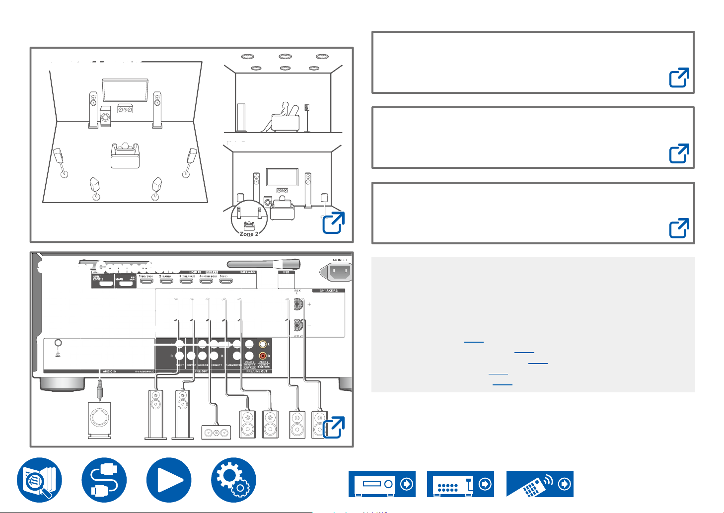
Table of contents
Z
2
Zone 2
Main Room
Roo
Speaker Layout
Main Room
Firmware Update
Troubleshooting
m
Supplementary Information
Speaker Connections
Zone 2Zone 2
one
Reducing the Power Consumption in Standby
State
When the following functions are enabled, the power consumption in
standby state increases. To reduce the power consumption in standby state,
check each setting and set the functions to "Off".
– HDMI CEC ( →p124)
– HDMI Standby Through ( →p124)
– USB Power Out at Standby ( →p131)
– Network Standby ( →p131)
– Bluetooth Wakeup ( →p132)
Detailed contents (Next page)
2
Page 3
Before starting the procedure 6
Firmware Update 7
Update Information of the rmware 7
Firmware Update Procedure 7
Part Names 10
Front Panel 10
Display 12
Rear Panel 13
Remote Controller 15
Inputting Characters 17
Speaker Layout
Connections
Notes regarding connections with HDMI cables 47
Connections 47
Connecting the TV 48
To ARC/eARC TV 48
To Non-ARC TV 48
Connecting the SUB Monitor 49
SUB Monitor 49
Connecting Playback Devices 50
Connections to BD/DVD and GAME with HDMI
jacks 50
The listening room and the speaker layout 19
5.1 Channel System 20
7.1 Channel System 21
5.1.2 Channel System 22
7.1.2 Channel System 23
5.1.4 Channel System 24
Speaker Installation
Speaker Connections
Speakers you can use with this unit and cable
connections 32
Connecting a Power Amplier 45
Connecting a BD/DVD without HDMI Jack Mounted 51
Connecting an Audio Component 52
Connecting a Video Camera, etc. 53
Connecting a TV or Integrated Amplier in a separate
room (Multi-zone) 54
Connecting a TV (ZONE 2) 54
Connecting an Integrated Amplier (ZONE 2) 55
Connecting an Integrated Amplier (ZONE 3) 56
Connecting Antennas 57
Network Connection 58
Connecting External Control Devices 59
IR IN/OUT port 59
12V TRIGGER OUT jack 60
Connecting the Power Cord 61
3
Page 4
Playback
Playing audio from an externally connected device 63
Basic Operations 63
BLUETOOTH
Playing audio from BLUETOOTH wireless technology
enabled devices with this unit 64
Transmitting audio from this unit to BLUETOOTH
wireless technology enabled devices 65
Listening To the Radio 67
Listening To the AM/FM Radio 67
Presetting a Radio Station 70
Listening Mode 71
Selecting a Listening mode 71
Quick Menu 73
Menu operations 73
Spotify 76
AirPlay
®
Basic Operations 77
Playing Back on multiple devices (AirPlay2) 78
DTS Play-Fi
Playing Back 79
Amazon Alexa 80
Registering this unit with an Amazon account 80
Operating this unit 81
®
Playback 64
®
77
79
Amazon Music 82
Registering This Unit with Amazon Music 82
Playing Amazon Music using the Integra
Control Pro 83
Playing Amazon Music using the remote controller 83
TIDAL 84
Registering this unit with TIDAL 84
Playing TIDAL 84
Connecting the Sonos System for Playback 85
Necessary Equipment 85
How to Connect This Unit and Sonos Connect 85
Setting Up 85
Playing Sonos on This Unit 86
Internet Radio 87
Playing Back 87
Multi-zone 89
Playing Back (ZONE 2) 90
Playing Back (ZONE 3) 92
Playing different audio and video 94
Displaying Your Favorite Video on TV While Playing
Music 94
Playing music les saved on a USB storage device 95
USB Storage Device Requirements 96
Music Server 97
4
Page 5
Windows Media® Player 12 settings 97
Operations 142
Playing Back 98
Play Queue 100
Adding Play Queue Information 100
Sort and Delete 100
Playing Back 101
Connecting a transmitter for playback 102
Connections 102
Setting Up 102
Playing Back 102
Setup
Setup Menu 104
Menu list 104
1. Input/Output Assign 107
2. Speaker 112
3. Audio Adjust 118
4. Source 121
5. Listening Mode Preset 123
6. Hardware 124
7. Multi Zone 137
8. Miscellaneous 139
Web Setup 141
Menu operations 141
Initial Setup with Auto Start-up Wizard 142
1. Speaker Setup 143
2. Multi Zone Sound Check 144
3. ARC Setup 144
4. Room EQ 144
Integra Control Pro 148
Main features 148
Initial Setup 148
Dirac Live 149
Measuring with Dirac Live 149
Using Dirac Live 150
Manual Adjust 150
Troubleshooting
Before starting the procedure 153
When the unit is operating erratically 154
Troubleshooting 155
Appendix
Speaker Layouts and Selectable Listening Modes 167
Listening Mode buttons and Selectable
Listening Modes 170
Input Formats and Selectable Listening Modes 172
Listening Mode Effects 176
Speaker Combinations 181
General Specications 182
5
Page 6
Before starting the procedure
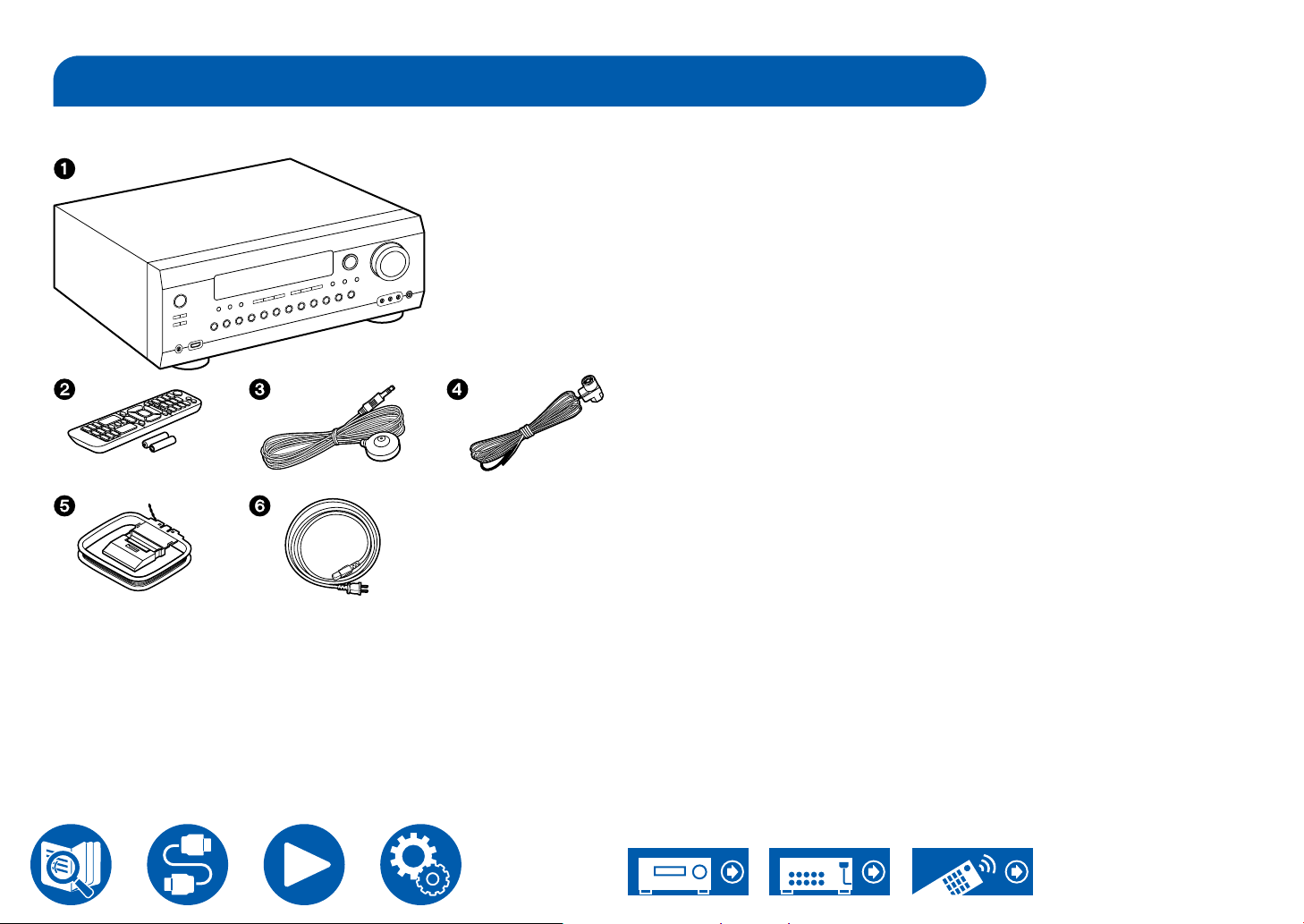
What's in the box
1. Main unit (1)
2. Remote controller (RC-973R) (1), Batteries (AAA/R03) (2)
3. Speaker setup microphone (1)
• Used during Initial Setup.
4. Indoor FM antenna (1)
5. AM loop antenna (1)
6. Power cord (1)
• Initial Setup Guide (1)
* This is an online user manual. This is not supplied with the product.
Note
• Connect speakers with an impedance of 4 Ω to 16 Ω.
• The power cord must be connected only after all other connections are
completed.
• We will not accept any responsibility for damage arising from the connection
with equipment manufactured by other companies.
• Network services and content that can be used may no longer be available
if new functions are added by updating rmware or the service providers
terminate their services. Also, available services may differ depending on
your area.
• Details on the rmware update will be posted on our website and through
other means at a later date.
• The illustrations in this manual use those of North American models unless
otherwise mentioned.
• Specications and appearance are subject to change without prior notice.
6
Page 7
Firmware Update
This unit is equipped with a function to update the rmware via network or USB
port when the rmware update is announced after purchase. This enables
various functions to be added and operations to be improved.
Depending on the manufacturing timing of the product, the rmware may be
switched to the updated one. In such a case, new functions may be added
from the star t. For how to conrm the latest rmware contents and the rmware
version of your product, see the following section.
Update Information of the rmware
For the latest rmware contents and the rmware version, visit our company's
website. If the rmware version of your product differs from the latest one, it is
recommended to update the rmware.
To conrm the rmware version of your product, press the button on the
remote controller, and refer to "8. Miscellaneous" - "Firmware Update" "Version" ( →p139).
Firmware Update Procedure
The update may take approx. 20 minutes to complete via network or via USB
port. Existing settings are guaranteed in either updating method.
When this unit is connected to the network, notications of rmware updates
may be displayed. To update the rmware, select "Update Now" with the cursor
buttons of the remote controller and press Enter. The unit automatically enters
standby mode after "Completed!" is displayed, and the update is completed.
Disclaimer: The program and accompanying online documentation are
furnished to you for use at your own risk.
Our company will not be liable and you will have no remedy for damages for
any claim of any kind whatsoever concerning your use of the program or the
accompanying online documentation, regardless of legal theory, and whether
arising in tort or contract.
In no event will our company be liable to you or any third party for any special,
indirect, incidental, or consequential damages of any kind, including, but not
limited to, compensation, reimbursement or damages on account of the loss of
present or prospective prots, loss of data, or for any other reason whatsoever.
Updating the Firmware via Network
• While updating the rmware, do not do the following:
– Disconnecting and reconnecting cables, USB storage device, speaker
setup microphone or headphones, or performing operations on the unit
such as turning the power off
– Accessing this unit from a PC or smartphone using their applications
• Check that the unit is turned on, and the connection to the Internet is secured.
• Turn off control devices (PC etc.) connected to the network.
• Stop an Internet radio, USB storage device, or server content being played.
• If the multi-zone function is active, turn it off.
• If "HDMI CEC" is set to "On", set it to "Off".
– Press . Next, select "6. Hardware" - "HDMI" and press Enter, then select
"HDMI CEC" and select "Off".
* The descriptions may differ from the actual on-screen displays, however, operations
and functions are the same.
Update
1. Press .
The Setup menu is displayed on the TV screen.
2. Select "8. Miscellaneous" - "Firmware Update" - "Update via NET" with the
cursors in order, then press Enter.
• If "Firmware Update" is grayed out and cannot be selected, wait for a while
until it starts up.
• If there is no updatable rmware, "Update via NET" cannot be selected.
3. Press Enter with "Update" selected, and start update.
• During the update, the TV screen may go black depending on the program
to be updated. In such a case, check the progress on the display of the
unit. The TV screen will remain black until the update is completed and the
power is turned on again.
• When "Completed!" is displayed, the update is complete.
4. Press On/Standby on the main unit to turn the unit into standby mode. The
process is completed, and your rmware is updated to the latest version.
• Do not use on the remote controller.
If an Error Message is Displayed
If an error occurs, "- Error!" is displayed on the display of the unit. (""
7
Page 8
represents an alphanumeric character.) Refer to the following descriptions and
check.
Error Code
• - 01, -10:
Ethernet cable not found. Connect the Ethernet cable properly.
• -02, -03, -04, -05, -06, -11, -13 , -14, -16, -17, -18, -20,
-21:
Internet connection error. Check the following:
– Whether the router is turned on
– Whether this unit and the router are connected via the network
Unplug and plug the power cords of this unit and the router. This may solve
the problem. If you are still unable to connect to the Internet, the DNS server
or proxy server may be temporarily down. Check the server operation status
with your Internet service provider.
• Others:
After removing the power plug once, insert it to the outlet, and then start the
operation from the beginning.
Updating via USB
• While updating the rmware, do not do the following:
– Disconnecting and reconnecting cables, USB storage device, speaker
setup microphone or headphones, or performing operations on the unit
such as turning the power off
– Accessing this unit from a PC or smartphone using their applications
• Prepare a 1 GB or larger USB storage device. The format of USB storage
devices supports FAT16 or FAT32 le system format.
– Media inserted into a USB card reader may not be used for this function.
– USB storage devices equipped with the security function are not
supported.
– USB hubs and USB devices equipped with the hub function are not
supported. Do not connect these devices to the unit.
• Delete any data stored on the USB storage device.
• Turn off control devices (PC etc.) connected to the network.
• Stop an Internet radio, USB storage device, or server content being played.
• If the multi-zone function is active, turn it off.
• If "HDMI CEC" is set to "On", set it to "Off".
– Press . Next, select "6. Hardware" - "HDMI" and press Enter, then select
"HDMI CEC" and select "Off".
* Depending on the USB storage device or its content, long time may be required
for loading, the content may not be loaded correctly, or power may not be supplied
co rre ctl y.
* Our company will not be liable whatsoever for any loss or damage of data, or
storage failure arising from the use of the USB storage device. Please note this in
advance.
* The descriptions may differ from the actual on-screen displays, however, operations
and functions are the same.
Update
1. Connect the USB storage device to your PC.
2. Download the rmware le from the our company's website to your PC and
unzip.
Firmware les are named as below.
ON K AV R_R.zip
Unzip the le on your PC. The number of unzipped les and folders varies
depending on the model.
3. Copy all unzipped les and folders to the root folder of the USB storage
device.
• Make sure to copy the unzipped les.
8
Page 9
4. Connect the USB storage device to the USB port of this unit.
• If an AC adapter is supplied with the USB storage device, connect the AC
adapter, and use it with a household outlet.
• If the USB storage device has been partitioned, each section will be
treated as an independent device.
5. Press .
The Setup menu is displayed on the TV screen.
6. Select "8. Miscellaneous" - "Firmware Update" - "Update via USB" with the
cursors in order, then press Enter.
• If "Firmware Update" is grayed out and cannot be selected, wait for a while
until it starts up.
• If there is no updatable rmware, "Update via USB" cannot be selected.
7. Press Enter with "Update" selected, and start update.
• During the update, the TV screen may go black depending on the program
to be updated. In such a case, check the progress on the display of the
unit. The TV screen will remain black until the update is completed and the
power is turned on again.
• During the update, do not turn the power off, or disconnect or reconnect
the USB storage device.
• When "Completed!" is displayed, the update is complete.
8. Disconnect the USB storage device from the unit.
9. Press On/Standby on the main unit to turn the unit into standby mode. The
process is completed, and your rmware is updated to the latest version.
• Do not use on the remote controller.
If an Error Message is Displayed
If an error occurs, "- Error!" is displayed on the display of the unit. (""
represents an alphanumeric character.) Refer to the following descriptions and
check.
Error Code
• - 01, -10:
The USB storage device cannot be recognized. Check if the USB storage
device or USB cable is securely inserted to the USB port of the unit.
Connect the USB storage device to an external power source if it has its own
power supply.
• -05, -13, -20, -21:
The rmware le is not present in the root folder of the USB storage device,
or the rmware le is for another model. Retry from the download of the
rmware le.
• Others:
After removing the power plug once, insert it to the outlet, and then start the
operation from the beginning.
9
Page 10
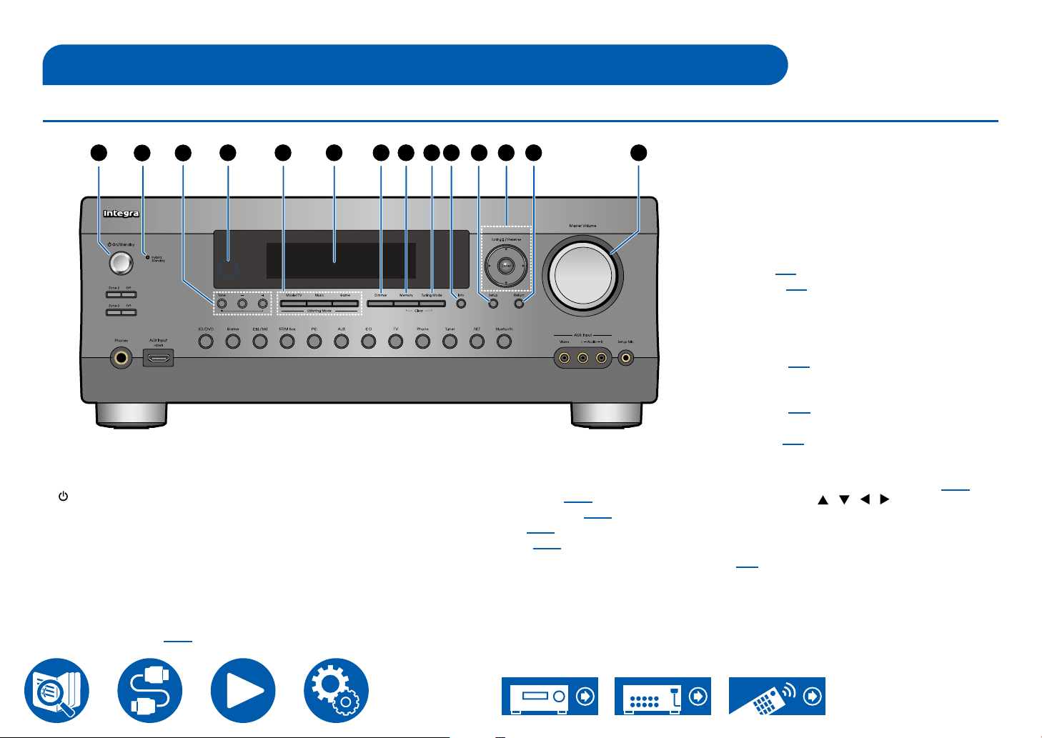
Part Names
Front Panel
1 4
1. On/Standby button
2. Hybrid Standby indicator: Lights up when any
of the following functions is working or enabled
in standby state of this unit. When this indicator
is lighting, the power consumption in standby
state increases, however, the increase in power
consumption is minimized by entering the Hybrid
Standby mode where only the essential circuits
operate.
– HDMI CEC ( →p124)
32
10
98765
– HDMI Standby Through ( →p124)
– USB Power Out at Standby ( →p131)
– Network Standby ( →p131)
– Bluetooth Wakeup ( →p132)
3. To n e button: You can adjust the sound quality of
the speakers. Press the Tone button to select an
item to adjust from "Bass", "Vocal" and "Treble",
and press + and - to adjust.
11 12 13 14
4. Remote control sensor: Receives signals from
the remote controller.
• The reception range of the remote controller
is within a distance of approx. 16´/5 m, and
an angle of 20° in vertical direction and 30° to
right and left.
5. Listening Mode button: Press "Movie/TV",
"Music" or "Game" button to change the listening
mode. ( →p71).
6. Display ( →p12)
7. Dimmer button: Switches the brightness of the
display with three levels. It cannot be turned off
completely.
8. Memory button: Used to register AM/FM radio
stations. ( →p70)
9. Tuning Mode button: Used to switch between
automatic tuning and manual tuning for AM/FM
stations. ( →p67)
10.
Info button: Switches the information on the
display. ( →p72)
11.
Setup button: You can display advanced setting
items on the TV and the display to have a more
enjoyable experience with this unit. ( →p104)
12.
Cursor buttons ( / / / ) and Enter
button: Select an item with the cursors, and
press Enter to conrm your selection. When
using TUNER, use them to tune in to stations.
( →p67)
13.
Return button: Returns the display to the
previous state while setting.
14.
Master Volume
10
Page 11
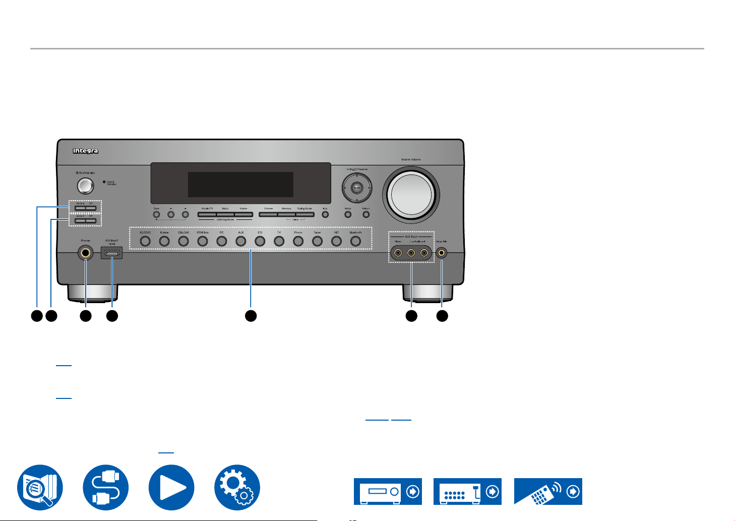
Front Panel
15 16 17 18
15.
Zone 2 button: Controls the multi-zone function.
( →p90)
Off button: Switches the multi-zone function off.
16.
Zone 3 button: Controls the multi-zone function.
( →p92)
Off button: Switches the multi-zone function off.
17.
Phones jack: Connect headphones with a
standard plug (ø1/4″/6.3 mm).
18.
AUX Input HDMI jack: Connect a video camera,
etc. using a HDMI cable. ( →p53)
19
19.
Input selector buttons: Switches the input to be
played.
20.
AUX Input Video/Audio jacks: Input the video
and audio signals from an external player with an
analog audio/video cable.
21.
Setup MIC jack: Connect the supplied speaker
setup microphone. ( →p145, p147)
2120
11
Page 12
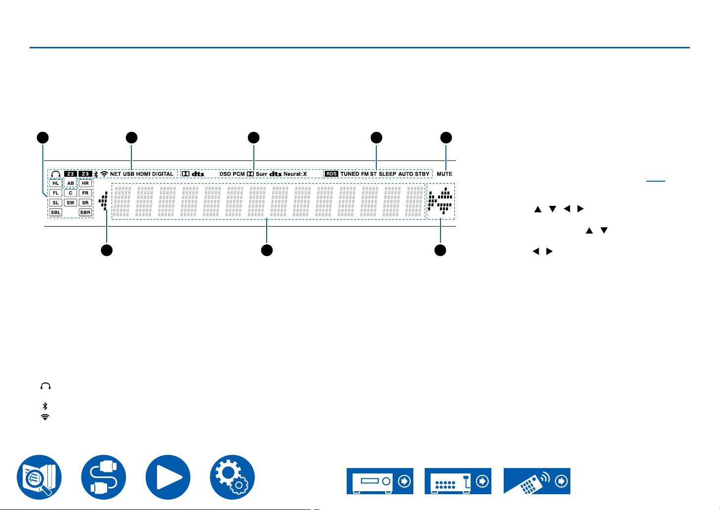
Display
1
2 4 53
5 76
B: Audio is output only to ZONE B.
AB: Audio is output to both ZONE A and ZONE
B.
3. Lights according to the type of input digital audio
signal and the listening mode.
4. Lights in the following conditions.
RDS (Australian models): Receiving RDS
broadcasting.
TUNED: Receiving AM/FM radio
FM ST: Receiving FM stereo.
SLEEP: Sleep timer is set.
AUTO STBY: Auto Standby is set. ( →p131)
5. Blinks when muting is on.
6. Displays various information of the input signals.
7. Cursors ( / / / ): These may light when
performing operations while “NET” is selected
with the input selector. / light when there are
multiple folders or les that are available to be
selected. / light when text information does
not t with the range provided by “6”.
1. Speaker/Channel display: Displays the output
channel that corresponds to the selected
listening mode.
2. Lights in the following conditions.
: Headphones are connected.
Z2/Z3: ZONE 2/ZONE 3 is on.
: Connected by BLUETOOTH.
: Connected by Wi-Fi.
NET: Lights when connected to the network with
the "NET" input selector. It will blink if incorrectly
connected to the network.
USB: Lights when the "NET" input selector is
selected, a USB device is connected and the
USB input is selected. It will blink if the USB
device is not properly connected.
HDMI: HDMI signals are input and the HDMI
input is selected.
DIGITAL: Digital signals are input and the digital
input is selected.
A: Audio is output only to ZONE A.
12
Page 13
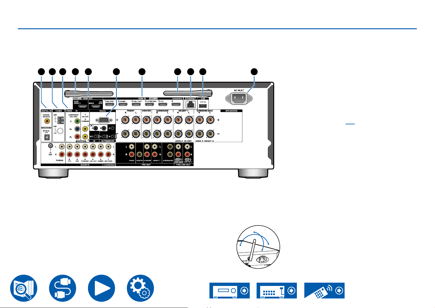
Rear Panel
5. HDMI OUT jacks: Transmit video signals and
audio signals with an HDMI cable connected to a
monitor such as a TV or projector.
6. RS232 port: Connect a home control system
equipped with an RS-232C port. For installing
9
8765321 4 4
10
a home control system, contact the specialized
stores.
7. HDMI IN jacks: Transmit video signals and audio
signals with an HDMI cable connected to an AV
component.
8. ETHERNET port: Connect to the network with
an Ethernet cable.
9. USB port: Connect a USB storage device to
play music les ( →p95). You can also supply
power (5 V/1 A) to USB devices with a USB
cable.
10.
AC INLET: Connect the supplied power cord.
1. DIGITAL IN OPTICAL/COAXIAL jacks: Input
TV or AV component digital audio signals with a
digital optical cable or digital coaxial cable.
2. TUNER AM/FM terminal: Connect the supplied
antennas.
3. COMPONENT VIDEO IN jacks: Input AV
component video signals with a component
video cable. (Compatible only with 480i or 576i
resolution.)
VIDEO IN jacks: Input AV component video
signals with an analog video cable.
4. Wireless antenna: Used for WI-Fi connection or
when using a BLUETOOTH enabled device.
Adjust the angles according to
the connection status.
90°
180°
13
Page 14
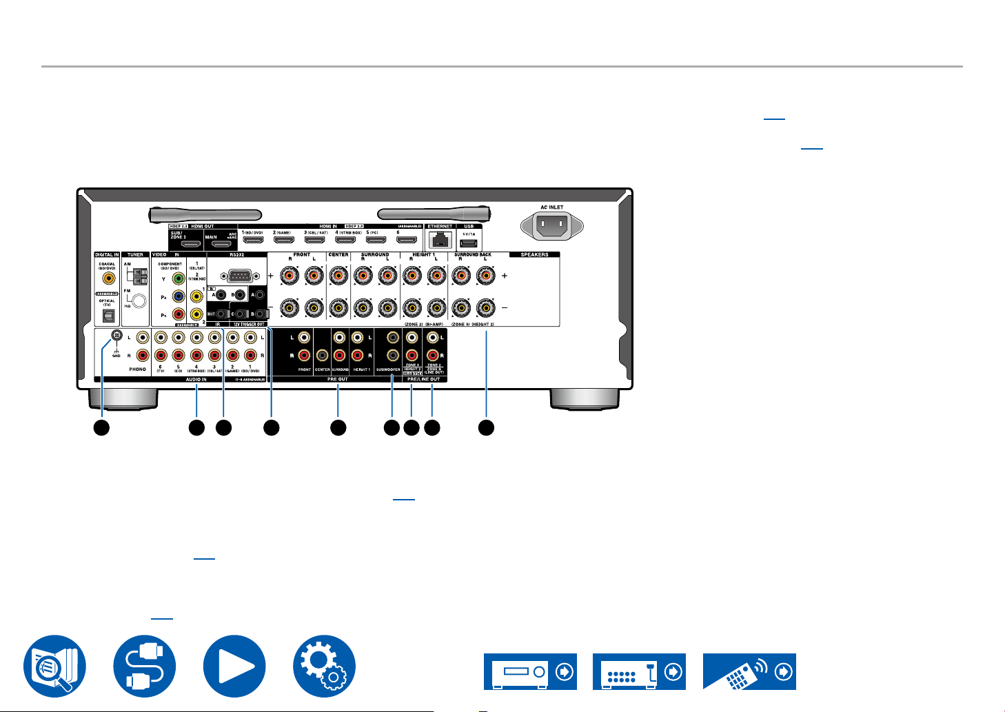
Rear Panel
11 12 13 14 15 16 17 18 19
(ZONE 3).
HEIGHT 2 PRE OUT jacks: Connect to a power
amplier. ( →p45)
SURR BACK PRE OUT jacks: Connect to a
power amplier. ( →p45)
18.
ZONE 2 PRE/LINE OUT jacks: Output audio
signals with an analog audio cable connected
to an integrated amplier in a separate room
(ZONE 2).
ZONE B LINE OUT jacks: Simultaneously
output the same audio source as the speakers
(ZONE A) connected to this unit by connecting
this unit to wireless headphones, wireless
speaker transmitter, etc., using an analog audio
cable.
19.
SPEAKERS terminals: Connect speakers with
speaker cables. (North American models support
banana plugs. Use a plug 4 mm in diameter.) Y
plug connection is not supported.
11.
GND terminal: Connect the ground wire of the
turntable.
12.
AUDIO IN jacks: Input AV component audio
signals with an analog audio cable.
13.
IR IN A/B, IR OUT Por t: Connect a remote
control receiver unit. ( →p59)
14.
12V TRIGGER OUT A/B/C jack: Connect a
device equipped with a 12V trigger input jack to
enable power link operation between the device
and this unit. ( →p60)
15.
PRE OUT jacks: Connect to a power amplier.
( →p45)
16.
SUBWOOFER PRE OUT jacks: Connect a
powered subwoofer with a subwoofer cable.
Up to two powered subwoofers can be
connected. The same signal is output from each
SUBWOOFER PRE OUT jack.
17.
ZONE 3 PRE/LINE OUT jacks: Output audio
signals with an analog audio cable connected
to an integrated amplier in a separate room
14
Page 15
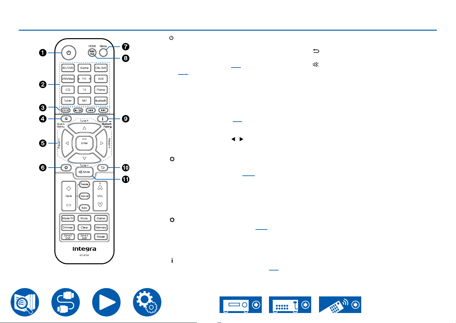
Remote Controller
1. On/Standby button
2. Input selector buttons: Switches the input to be
played.
3. Play buttons: Used for playback operations
for the Music Server ( →p97) or USB device
( →p95). Also, switching to "CEC MODE" with
"19. Mode button" allows you to operate an HDMI
CEC function-enabled AV component. (Some
devices may not be operated.)
4. Q (Quick Menu) button: Pressing this button
during playback allows you to make settings
such as "HDMI" and "Audio" quickly on the TV
screen while playing. ( →p73)
5. Cursor buttons and Enter button: Select an
item with the cursors, and press Enter to conrm
your selection. Pressing / button allows you
to switch the screen when a music folder list or
le list is not displayed on one screen on the TV.
6. button: Displays advanced setting items on
the TV or the display to have a more enjoyable
experience with this unit. ( →p104)
7. Sleep button: You can allow the unit to enter
standby automatically when the specied time
has elapsed. Select the time from "30 min",
"60 min", "90 min" and "Off". When you do not
want to turn the unit to standby automatically,
select "Off". You can also set this by pressing
button and selecting "6. Hardware" - "Power
Management" - "Sleep Timer" ( →p131) on the
Setup menu.
8. HDMI Main/Sub button: Select the HDMI OUT
jack to output video signals from "MAIN", "SUB",
and "MAIN+SUB".
9. button: Switches the information on the
display and is used to operate RDS ( →p68).
Also, when the "BLUETOOTH" input selector is
selected, pressing and holding this button for 5
seconds or more will switch to the pairing mode.
10.
button: Returns the display to the previous
state while setting.
11.
Mute button: Temporarily mutes audio. Press
the button again to cancel muting.
15
Page 16
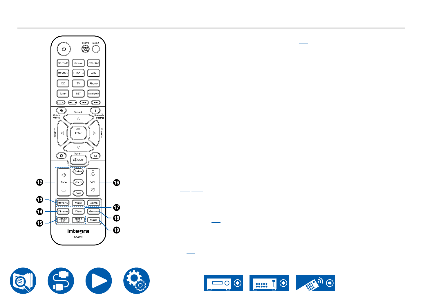
Remote Controller
12.
Tone buttons: Adjusts the sound quality. Press
"Treble", "Bass", or "Vocal" to select what you
want to adjust, then adjust with + and -.
Treble/Bass button: You can adjust the sound
quality of the speakers.
1.Press Treble or Bass to select the content to
adjust.
Treble: Enhances or moderates the high-tone
range of the speakers.
Bass: Enhances or moderates the low-tone
range of the speakers.
2. Press + or - to adjust.
Vocal button: Emphasizes movie dialogues
and music vocals to listen to them more easily.
It is effective to movie lines in particular. Also, it
exerts the effect even if the center speaker is not
used. Select a desired level from "1" (low) to "5"
(high).
1. Press Vocal.
2. Press + or - to adjust.
• Depending on the input source or listening
mode setting, selection is not possible, or the
desired effect may not be achieved.
13.
Listening Mode buttons: Selects a listening
mode ( →p71, p170).
14.
Dimmer button: Switches the brightness of the
display with three levels. It cannot be turned off
completely.
15.
Zone 2/Zone 3 Shift button: Used to control the
multi-zone function ( →p89).
16.
VOLUME buttons
17.
Clear button: Deletes all characters you have
entered when entering text on the TV screen.
18.
Memory button: Used to register AM/FM radio
stations. ( →p70)
19.
Mode button: Switches between automatic
tuning and manual tuning for AM/FM stations
( →p67). Also, when an HDMI CEC functionenabled AV component is connected to this unit,
you can switch "3. Play buttons" between "CEC
MODE" and "RCV MODE" (normal mode).
16
Page 17
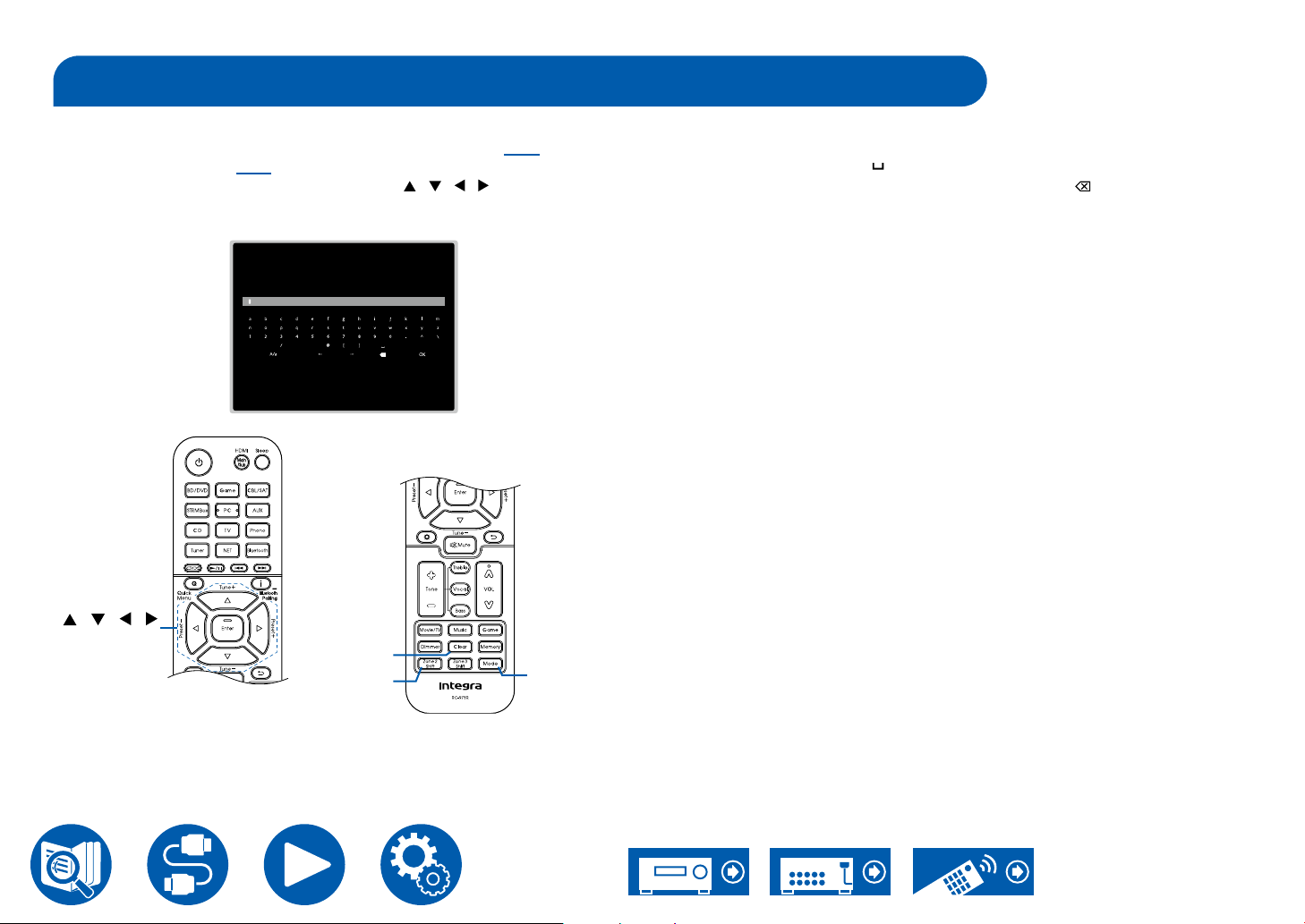
Inputting Characters
You can input characters or symbols on the keyboard displayed on the TV
screen such as when inputting a password for Wi-Fi Setup ( →p126) or naming
a preset radio station ( →p121).
1. Select a character or symbol with the cursors / / / on the remote
controller and press the Enter button.
2. When saving characters after input, select "OK" and press the Enter button.
, . ;/ : ], . ; :
/ / /
Enter
Clear
Zone 2
Mode
Shift
• Select "A/a" to switch between upper and lower cases. (Can also be switched
with the Mode button on the remote controller.)
• To enter a space, select " ".
• To delete a character on the left of the cursor, select " ".
• To delete all the input characters, press the Clear button on the remote
control.
• On the ZONE 2 playback screen, operate the remote controller while pressing
and holding the Zone 2 Shift button. To delete all the input characters, only
press the Clear button without pressing the Zone 2 Shift button.
17
Page 18
Speaker Layout
Speaker Layout
This unit can be used in different ways, depending on the layout of the
speakers you are installing. Select the speaker layout that suits the installation
environment, then conrm the methods for installation and connection.
Speaker layout ( →p20)
Speaker Installation ( →p26)
Speaker Connections ( →p31)
Speaker Combinations ( →p181)
5.1c h
7.1c h
5.1. 2ch
7.1. 2 c h
5.1.4ch
18
Page 19
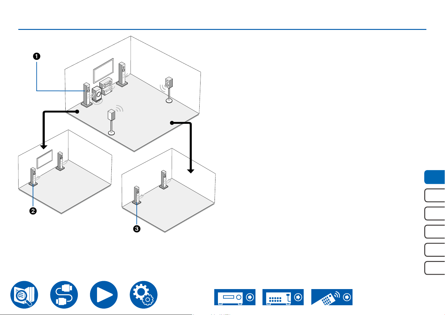
The listening room and the speaker layout
ZONE A
(Main Room)
Speaker Layout
1. ZONE A Speakers
The speaker system set up in the main room (where this unit is located).
2. ZONE 2 Speakers
The 2 ch speaker system set up in a separate room (Zone 2). This enables
you to play the same source in the main room and the separate at the same
time, or to play separate sources.
3. ZONE 3 Speakers
The 2 ch speaker system set up in a separate room (Zone 3). This enables
you to play the same source in the main room and the separate at the same
time, or to play separate sources.
ZONE 2
ZONE 3
5.1c h
7.1c h
5.1. 2ch
7.1. 2 c h
5.1.4ch
19
Page 20
Speaker Layout
Zone 2Zone 2
Zone 2Zone 2 Zone 3Zone 3
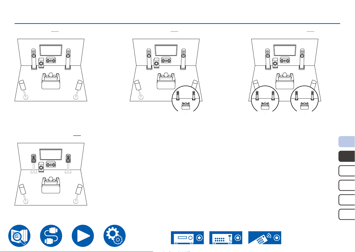
5.1 Channel System
Basic system ( →p27)
5.1 ch (Bi-Amping (Front)) ( →p27)
This is a basic 5.1 Channel System.
5.1 ch + ZONE 2 ( →p27)
Main Room
5.1 ch + ZONE 2/ZONE 3 ( →p27)
Main Room
5.1c h
7.1c h
5.1. 2ch
7.1. 2 c h
5.1.4ch
20
Page 21
Speaker Layout
Zone 2Zone 2
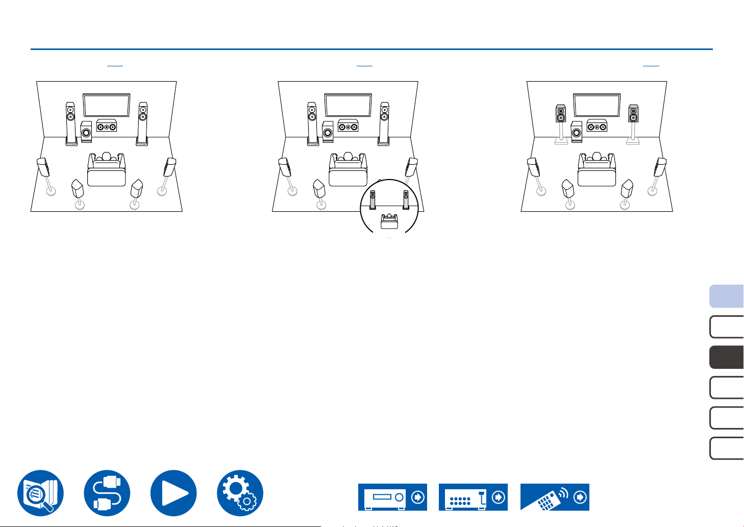
7.1 Channel System
Basic system ( →p27)
This is a 7.1 Channel System that consists of the basic 5.1 Channel System and added surround back speakers.
7.1 ch + ZONE 2 ( →p27) 7.1 ch (Bi-Amping (Front)) ( →p27)
Main Room
5.1c h
7.1c h
5.1. 2ch
7.1. 2 c h
5.1.4ch
21
Page 22
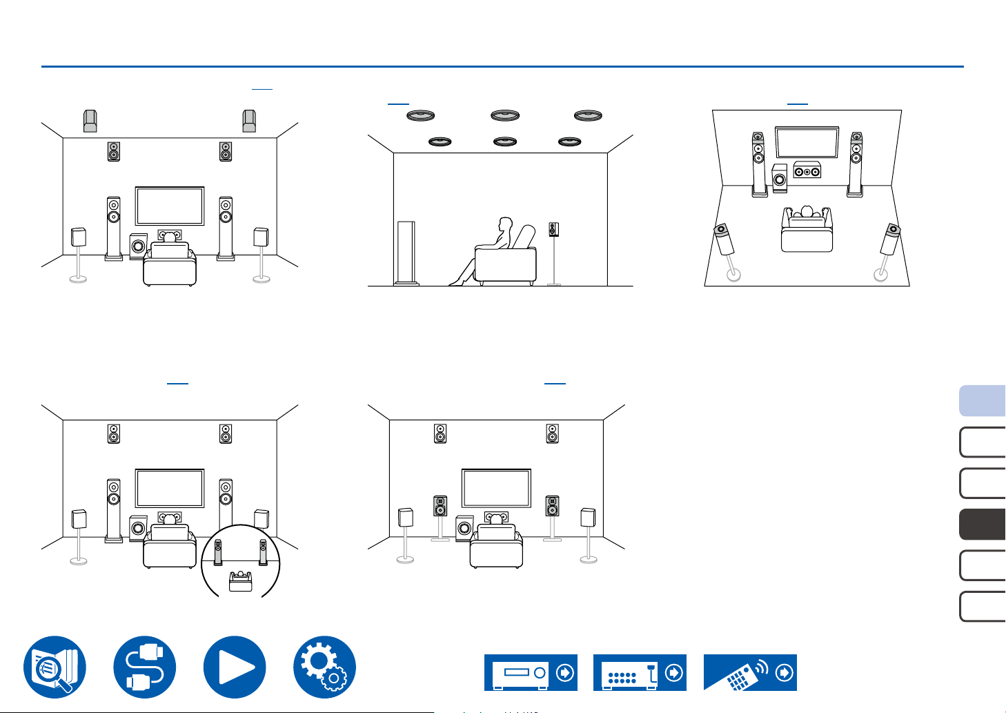
Speaker Layout
Zone 2Zone 2
Main Room
5.1.2 Channel System
5.1.2 ch (Front High or Rear High) ( →p28) 5.1.2 ch (Top Front or Top Middle or Top Rear)
5.1.2 ch + ZONE 2 ( →p28) 5.1.2 ch (Bi-Amping (Front)) ( →p28)
A Speaker System that is a 5.1 Channel System with one set of height speakers added.
( →p28)
5.1.2 ch (Dolby Enabled Speakers (Front or
Surround)) ( →p28)
5.1c h
7.1c h
5.1. 2ch
7.1. 2 c h
5.1.4ch
22
Page 23
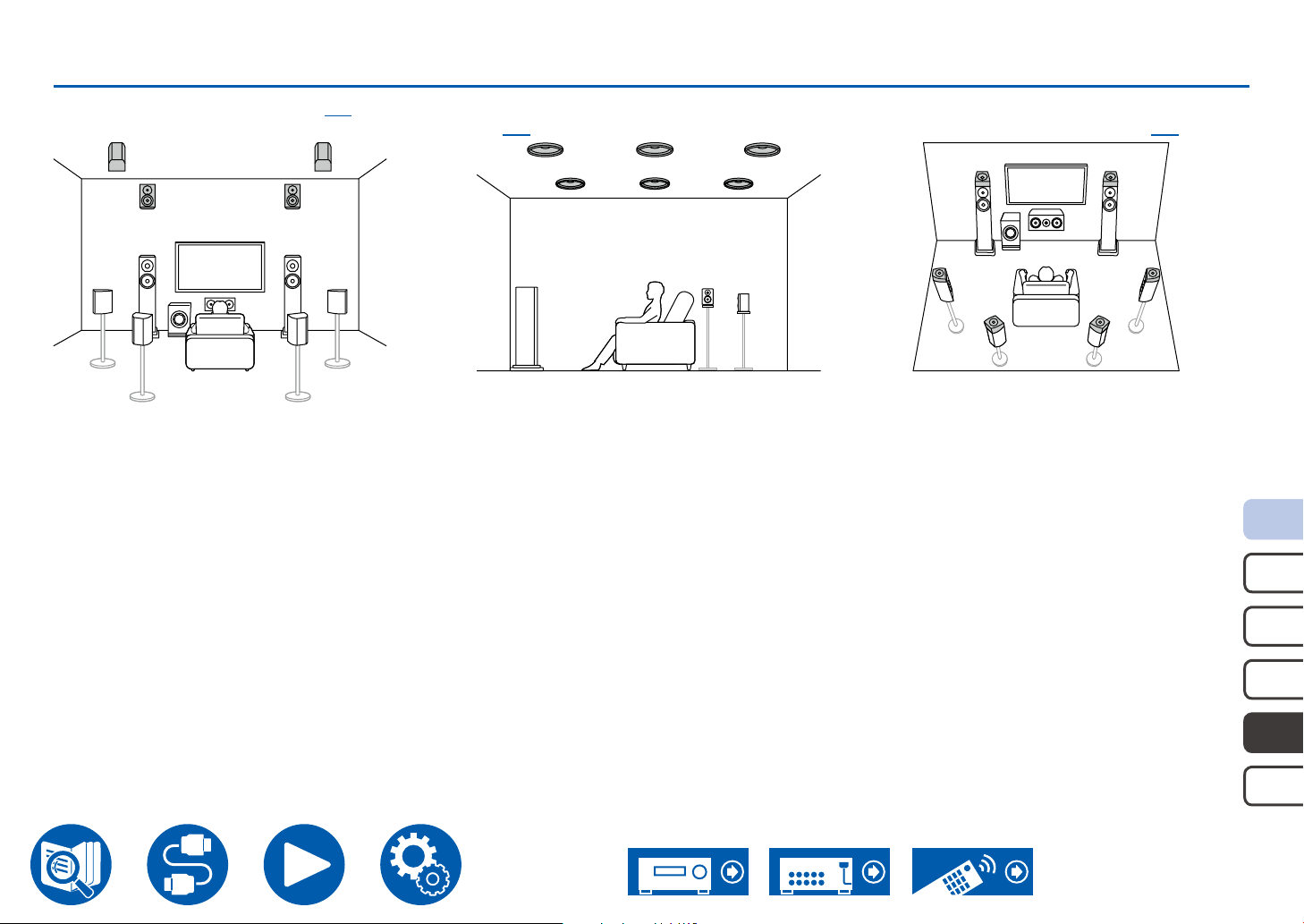
Speaker Layout
7.1.2 Channel System
7.1. 2 ch (Front High or Rear High) ( →p29) 7.1. 2 ch (Top Front or Top Middle or Top Rear)
A Speaker System that is a 7.1 Channel System with one set of height speakers added.
( →p29)
7.1. 2 ch (Dolby Enabled Speakers (Front or
Surround or Surround Back)) ( →p29)
5.1c h
7.1c h
5.1. 2ch
7.1. 2 c h
5.1.4ch
23
Page 24
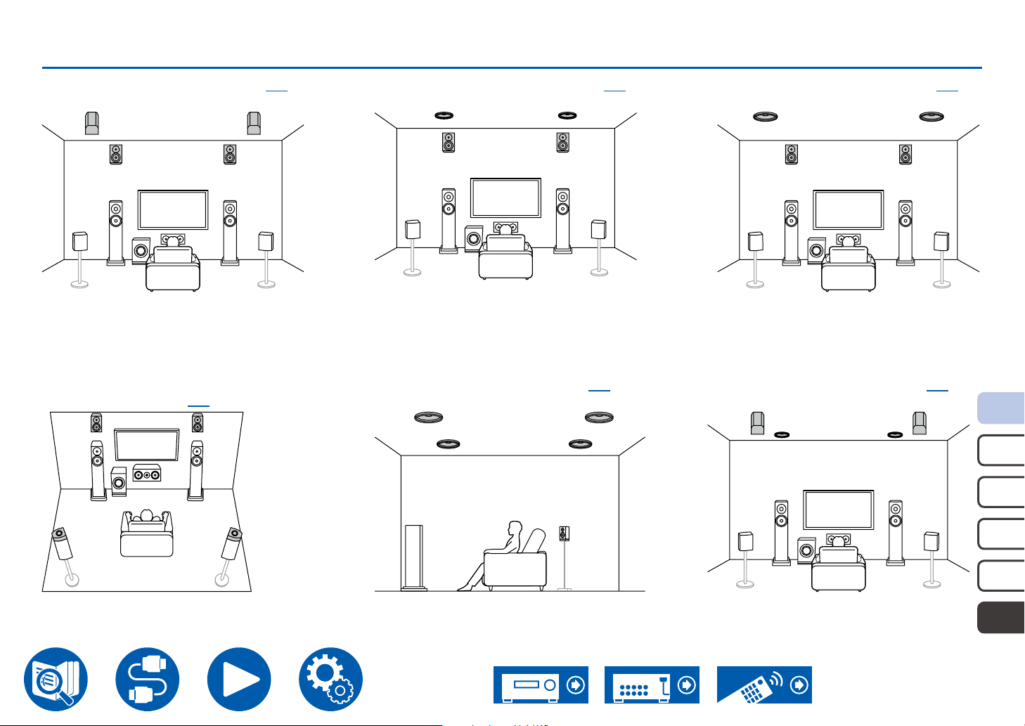
Speaker Layout
5.1.4 Channel System
5.1. 4 ch (Front High and Rear High) ( →p30) 5.1.4 ch (Front High and Top Middle) ( →p30)
5.1. 4 ch (Front High and Dolby Enabled
Speakers (Surround)) ( →p30)
A Speaker System that is a 5.1 Channel System with two sets of height speakers added.
5.1. 4 ch (Top Front and Top Rear) ( →p30) 5.1. 4 ch (Top Front and Rear High) ( →p30)
5.1. 4 ch (Front High and Top Rear) ( →p30)
5.1c h
7.1c h
5.1. 2ch
7.1. 2 c h
5.1.4ch
24
Page 25
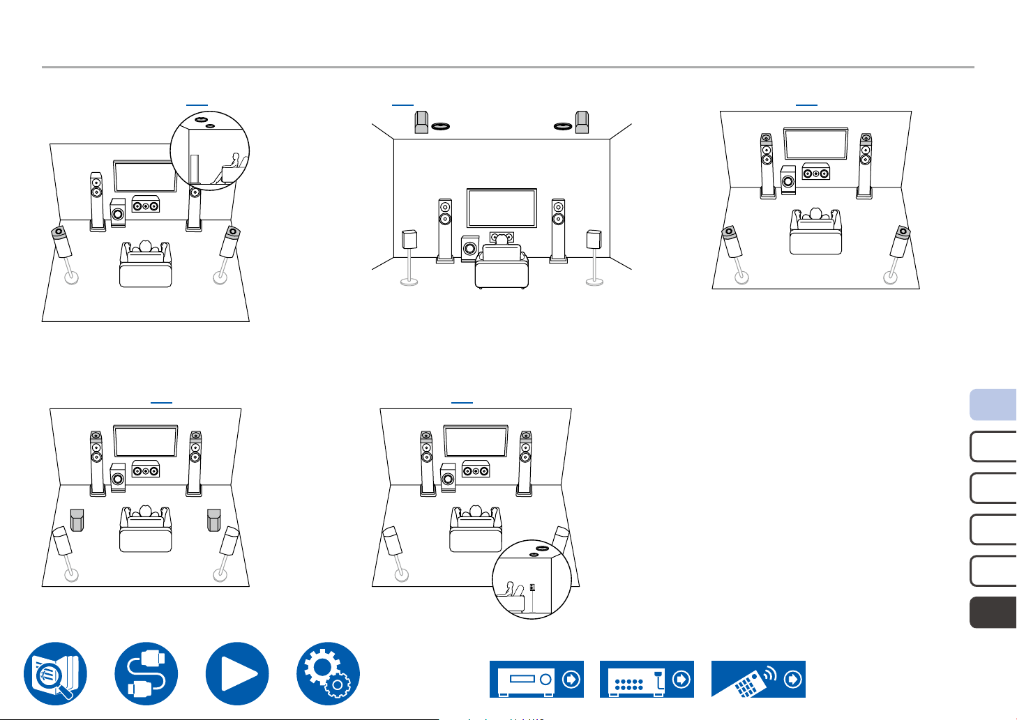
5.1.4 Channel System
Speaker Layout
5.1. 4 ch (Top Front and Dolby Enabled
Speakers (Surround)) ( →p30)
5.1. 4 ch (Dolby Enabled Speakers (Front)
and Rear High) ( →p30)
5.1. 4 ch (Top Middle and Rear High)
( →p30)
5.1. 4 ch (Dolby Enabled Speakers (Front) and
Top Rear) ( →p30)
5.1. 4 ch (Dolby Enabled Speakers (Front and
Surround)) ( →p30)
5.1c h
7.1c h
5.1. 2ch
7.1. 2 c h
5.1.4ch
25
Page 26
Speaker Installation
Speaker Installation
How the speakers are set up depends on the size and shape of the room, so
here we introduce just a basic layout example.
The alphabetic symbols used in this chapter represent the following speakers:
FL Front speaker Left
FR Front speaker Right
C Center speaker
SW powered SubWoofer
SL Surround speaker Left
SR Surround speaker Right
SBL Surround Back speaker Left
SBR Surround Back speaker Right
FHL Front High speaker Left
FHR Front High speaker Right
RHL Rear High speaker Left
RHR Rear High speaker Right
TFL Top Front speaker Left
TFR Top Front speaker Right
TML Top Middle speaker Left
TMR Top Middle speaker Right
TRL Top Rear speaker Left
TRR Top Rear speaker Right
DFL Dolby enabled speaker Front Left
DFR Dolby enabled speaker Front Right
DSL Dolby enabled speaker Surround Left
DSR Dolby enabled speaker Surround Right
DSBL Dolby enabled speaker Surround Back Left
DSBR Dolby enabled speaker Surround Back Right
5.1c h
7.1c h
5.1. 2ch
7.1. 2 c h
5.1.4ch
26
Page 27
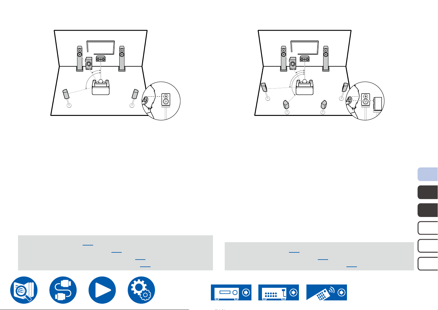
Speaker Installation
5.1 Channel System
FL FR
SW
b
SL SR
a: 22° to 30°, b: 120°
FL, FR Place the Left and Right Front Speakers to match ear height.
C The center speaker should be set up facing the listening position at
an angle.
SW Place the powered subwoofer between the center speaker and a
front speaker.
SL, SR Place the Left and Right Surround Speakers to be just above ear
height.
C
a
7.1 Channel System
FL FR
SW
SL SR
a: 22° to 30°, b: 90° to 110°, c: 135° to 150°
FL, FR Place the Left and Right Front Speakers to match ear height.
C The center speaker should be set up facing the listening position
at an angle.
SW Place the powered subwoofer between the center speaker and a
front speaker.
SL, SR Place the Left and Right Surround Speakers to be just above ear
height.
SBL, SBR Place the Left and Right Surround Back Speakers at ear height.
• If surround back speakers are installed, be sure to install surround
speakers as well.
b
c
SBL SBR
C
a
5.1c h
5.1 ch connection ( →p34)
5.1 ch + ZONE 2 connection ( →p35)
5.1 ch + ZONE 2/ZONE 3 connection ( →p35)
5.1 ch (Bi-Amping (Front)) connection ( →p36)
7.1 ch connection ( →p37)
7.1 ch + ZONE 2 connection ( →p38)
7.1 ch (Bi-Amping (Front)) connection ( →p39)
7.1c h
5.1. 2ch
7.1. 2 c h
5.1.4ch
27
Page 28
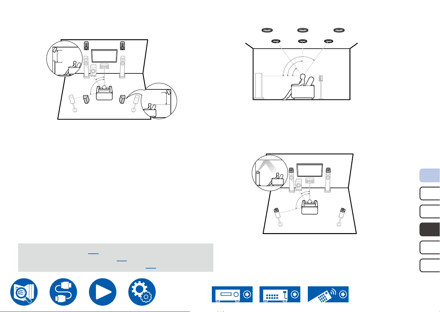
5.1.2 Channel System
TFL
TML
TRL
High Speakers
FHL FHR
3´ (0.9 m)
or more
a
b
RHL RHR
FHL, FHR Place the front high speakers directly above the front speakers,
angled to face the listening position.
RHL, RHR Place the rear high speakers so the lateral distance matches the
front speakers, angled to face the listening position.
a: 22° to 30°
b: 120 °
3´ (0.9 m)
or more
Speaker Installation
Top Speakers
TFR
TFL, TFR
Fit top front speakers on the ceiling in front of the listening position.
TML, TMR Fit top middle speakers on the ceiling directly above the listening
position.
TRL, TRR Fit top rear speakers on the ceiling behind the listening position.
• Match the lateral distance of the top speakers to the front speakers.
Dolby Enabled Speakers
TMR
c
b
a
DFL DFR
TRR
a: 30° to 55°
b: 65° to 100°
c: 125° to 150°
a: 22° to 30°
b: 120 °
5.1.2 ch connection ( →p40)
5.1.2 ch + ZONE 2 connection ( →p41)
5.1.2 ch (Bi-Amping (Front)) connection ( →p42)
a
b
DSL DSR
DFL, DFR The Dolby enabled speakers (front) are installed on top of the
front speakers.
DSL, DSR The Dolby enabled speakers (surround) are installed on top of the
surround speakers.
5.1c h
7.1c h
5.1. 2ch
7.1. 2 c h
5.1.4ch
28
Page 29
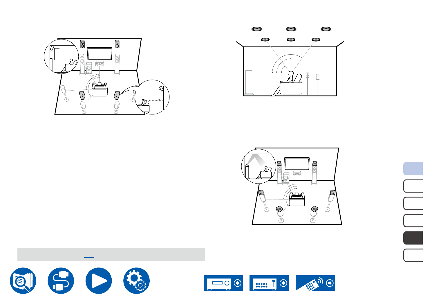
7.1.2 Channel System
TFL
TML
TRL
High Speakers
FHL FHR
3´ (0.9 m)
or more
b
Speaker Installation
Top Speakers
a: 22° to 30°
b: 90° to 110°
c: 135° to 150°
a
TFR
TMR
a
TRR
c
b
a: 30° to 55°
b: 65° to 100°
c: 125° to 150°
c
RHL RHR
3´ (0.9 m)
or more
FHL, FHR Place the front high speakers directly above the front speakers,
angled to face the listening position.
RHL, RHR Place the rear high speakers so the lateral distance matches the
front speakers, angled to face the listening position.
7.1.2 ch connection ( →p43)
TFL, TFR
Fit top front speakers on the ceiling in front of the listening position.
TML, TMR Fit top middle speakers on the ceiling directly above the listening
position.
TRL, TRR Fit top rear speakers on the ceiling behind the listening position.
• Match the lateral distance of the top speakers to the front speakers.
Dolby Enabled Speakers
a: 22° to 30°
DFL DFR
DSL DSR
DSBL DSBR
a
b
c
b: 90° to 110°
c: 135° to 150°
DFL, DFR The Dolby enabled speakers (front) are installed on top of the
front speakers.
DSL, DSR The Dolby enabled speakers (surround) are installed on top of the
surround speakers.
DSBL, DSBR
The Dolby enabled speakers (surround back) are installed on top
of the surround back speakers.
5.1c h
7.1c h
5.1. 2ch
7.1. 2 c h
5.1.4ch
29
Page 30
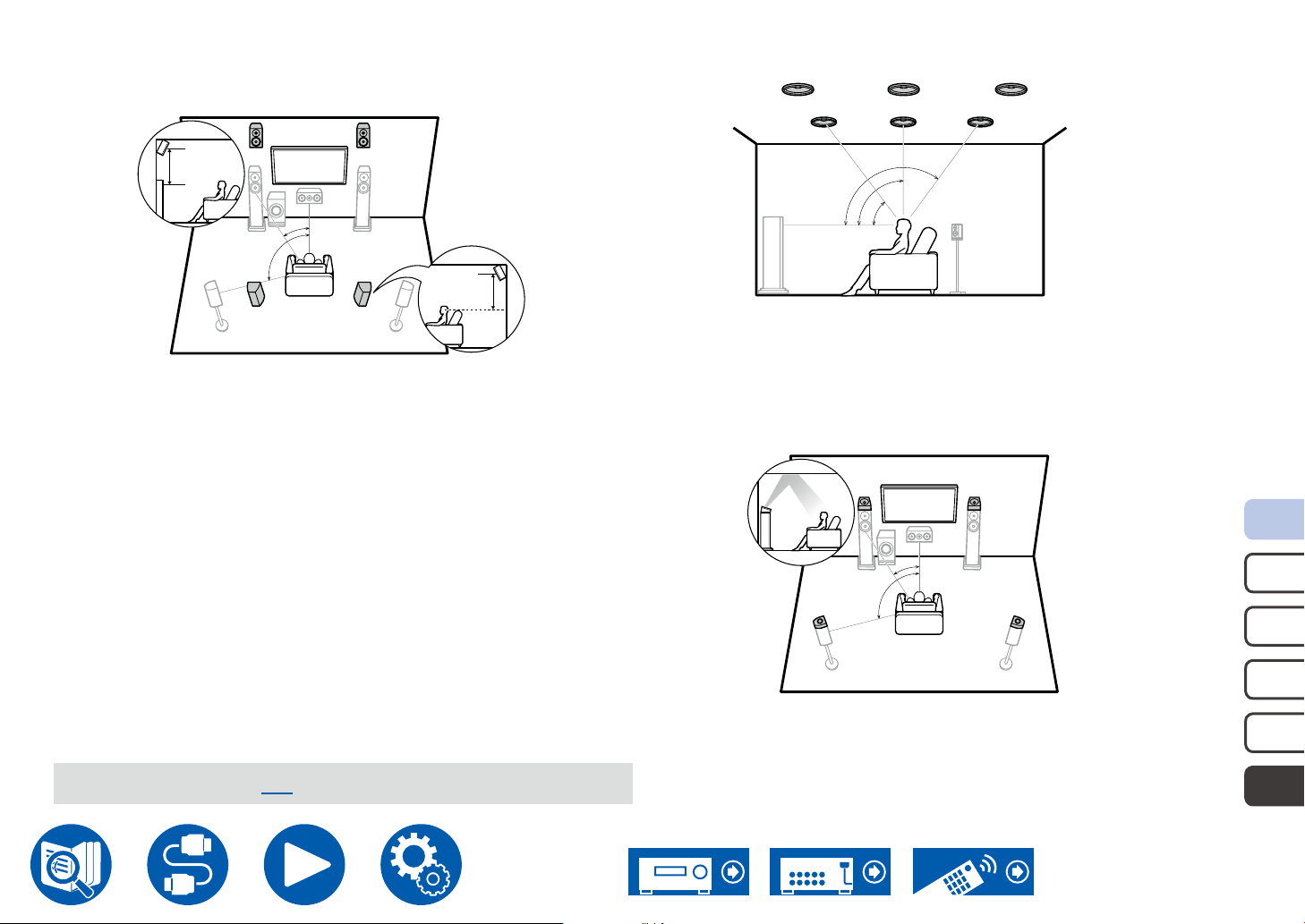
5.1.4 Channel System
TFL
TML
TRL
High Speakers
FHL FHR
3´ (0.9 m)
or more
a
b
RHL RHR
FHL, FHR Place the front high speakers directly above the front speakers,
angled to face the listening position.
RHL, RHR Place the rear high speakers so the lateral distance matches the
front speakers, angled to face the listening position.
a: 22° to 30°
b: 120 °
3´ (0.9 m)
or more
Speaker Installation
Top Speakers
TFR
TFL, TFR
Fit top front speakers on the ceiling in front of the listening position.
TML, TMR Fit top middle speakers on the ceiling directly above the listening
position.
TRL, TRR Fit top rear speakers on the ceiling behind the listening position.
• Match the lateral distance of the top speakers to the front speakers.
Dolby Enabled Speakers
TMR
c
b
a
DFL DFR
TRR
a: 30° to 55°
b: 65° to 100°
c: 125° to 150°
a: 22° to 30°
b: 120 °
5.1. 4 ch connection ( →p44)
a
b
DSL DSR
DFL, DFR The Dolby enabled speakers (front) are installed on top of the
front speakers.
DSL, DSR The Dolby enabled speakers (surround) are installed on top of the
surround speakers.
5.1c h
7.1c h
5.1. 2ch
7.1. 2 c h
5.1.4ch
30
Page 31
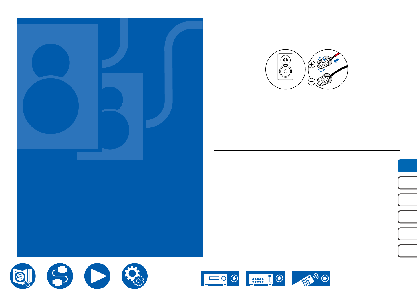
Speaker Connections
(Before starting the procedure)
Speakers you can use with this unit and cable
connections 32
4-16Ω
Speaker Connections
5.1 Channel System 34, 35, 36
7.1 Channel System 37, 38, 39
5.1.2 Channel System 40, 41, 42
7.1.2 Channel System 43
5.1.4 Channel System 44
Connecting a Power Amplier 45
5.1c h
7.1c h
5.1. 2ch
7.1. 2 c h
5.1.4ch
31
Page 32
Speaker Connections
Speakers you can use with this unit and cable connections
Speakers you can use with this unit
This unit supports speakers with 4 Ω to 16 Ω impedance. For speaker impedance, check the speaker instruction manual.
(Note) Speaker Impedance
If any of the speakers to be connected has an impedance of 4 Ω or more and less than 6 Ω, set "Speaker Impedance" to "4ohms" for "Speaker Setup" in the Initial
Setup section ( →p142). When setting "Speaker Impedance" from the Setup menu, press on the remote controller, and set "2. Speaker" - "Conguration" -
"Speaker Impedance" ( →p113) to "4ohms".
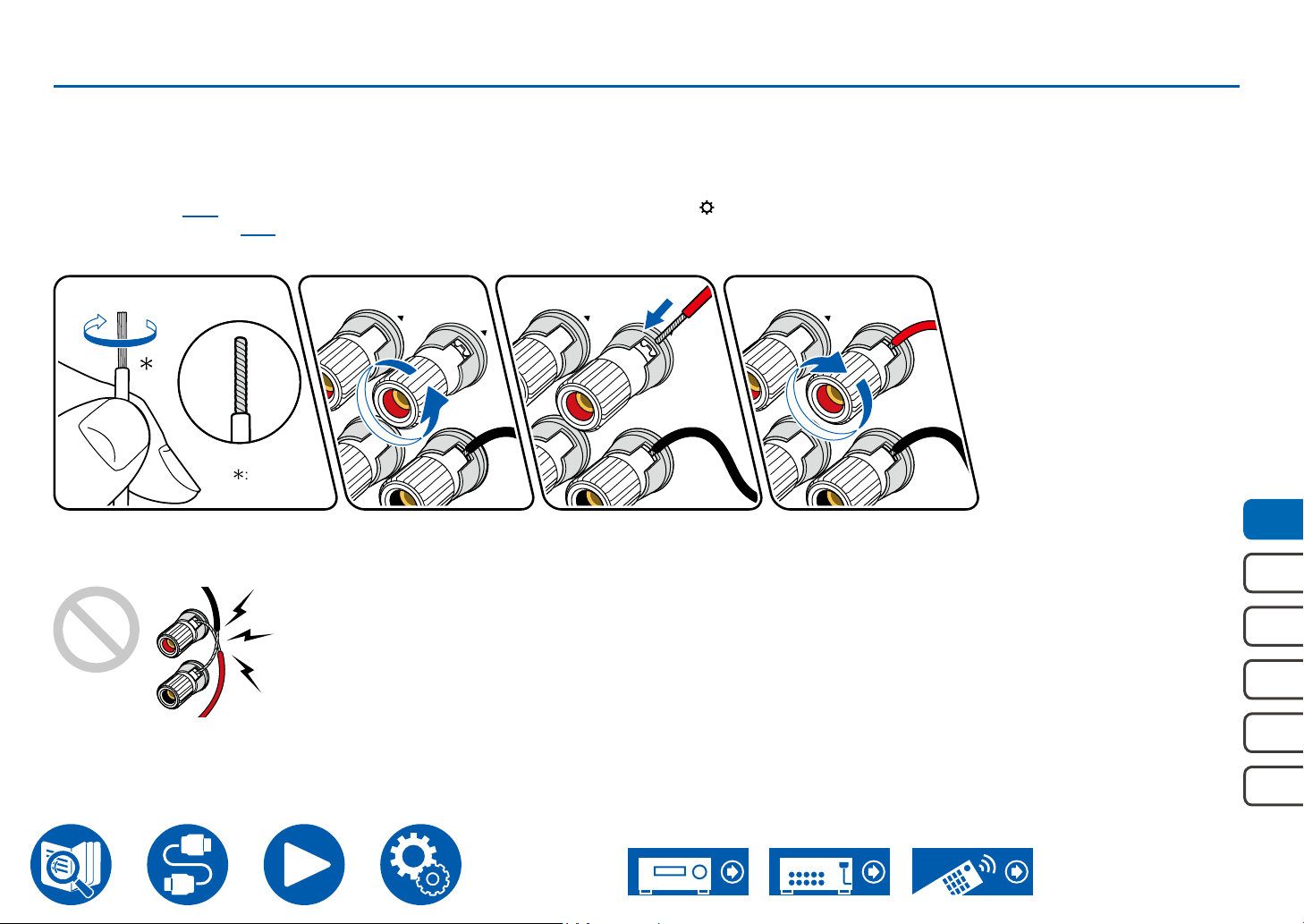
Connect the Speaker Cables
1/2˝
(12 mm)
Make correct connection between the unit's jacks and speaker's jacks (+ side to + side, and - side to - side) for each channel. If the connection is wrong, a bass
sound will not be reproduced properly due to reverse phase. Twist the wires exposed from the tip of the speaker cable so that the wires do not stick out of the
speaker terminal when connecting. If the exposed wires touch the rear panel, or the + side and – side wires touch each other, a malfunction may occur.
5.1c h
7.1c h
5.1. 2ch
7.1. 2 c h
5.1.4ch
32
Page 33
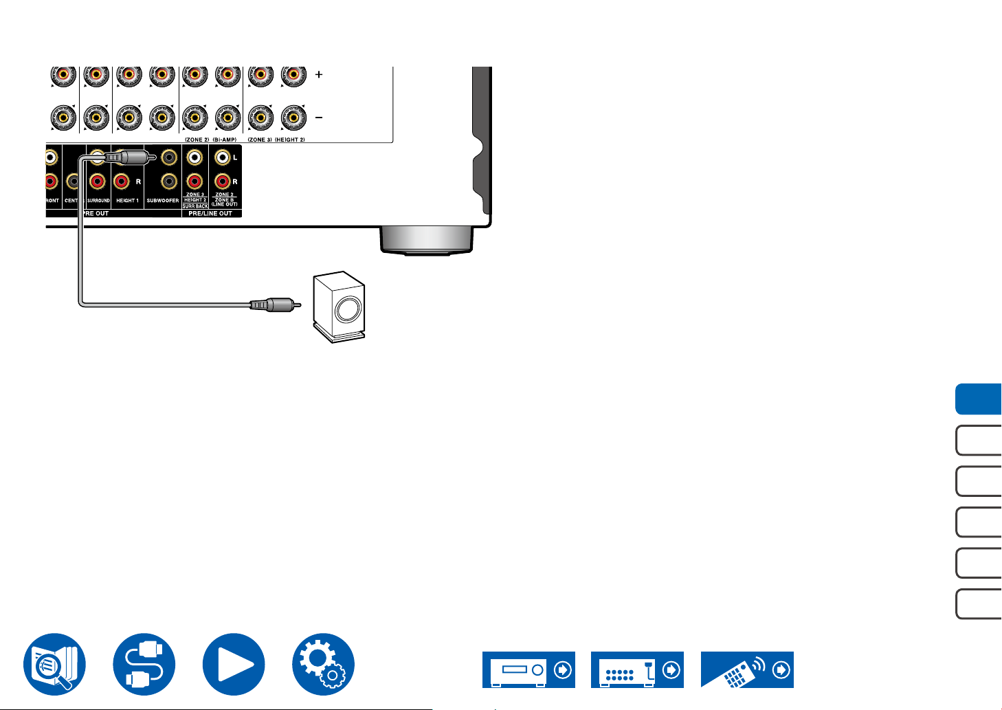
Connect the Subwoofer
a
a Subwoofer cable
Connect a powered subwoofer with this unit using a subwoofer cable. Up to two
powered subwoofers can be connected. The same signal is output from each
SUBWOOFER PRE OUT jack.
Speaker Connections
5.1c h
7.1c h
5.1. 2ch
7.1. 2 c h
5.1.4ch
33
Page 34
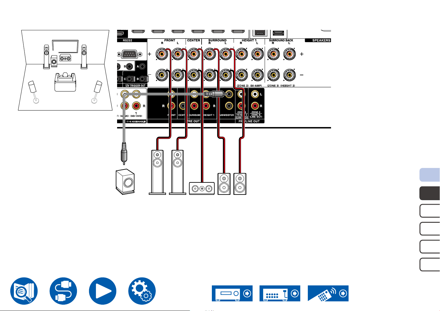
5.1 Channel System
FL FR
SW
SL SR
C
Speaker Connections
SW FR FL C SR SL
5.1c h
7.1c h
5.1. 2ch
7.1. 2 c h
5.1.4ch
34
Page 35
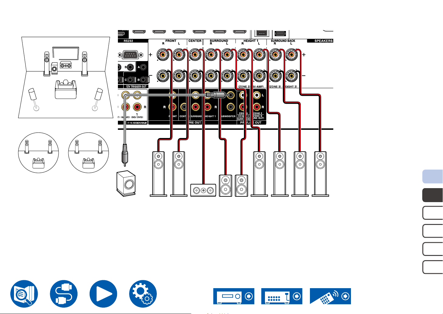
5.1 Channel System + ZONE SPEAKER
Main Room
FL FR
SW
SL SR
C
Speaker Connections
Zone 2
FL(Z2)FR(Z2)
To output audio from an externally connected AV component to ZONE 3, use an analog audio cable for connection. Note that ZONE 3 output is not possible with the
connection using a HDMI cable, digital coaxial cable, or digital optical cable.
Zone 3
FL(Z3)FR(Z3)
SW FR FL C
SR SL
FR(Z2) FL(Z2) FR(Z3) FL(Z3)
5.1c h
7.1c h
5.1. 2ch
7.1. 2 c h
5.1.4ch
35
Page 36
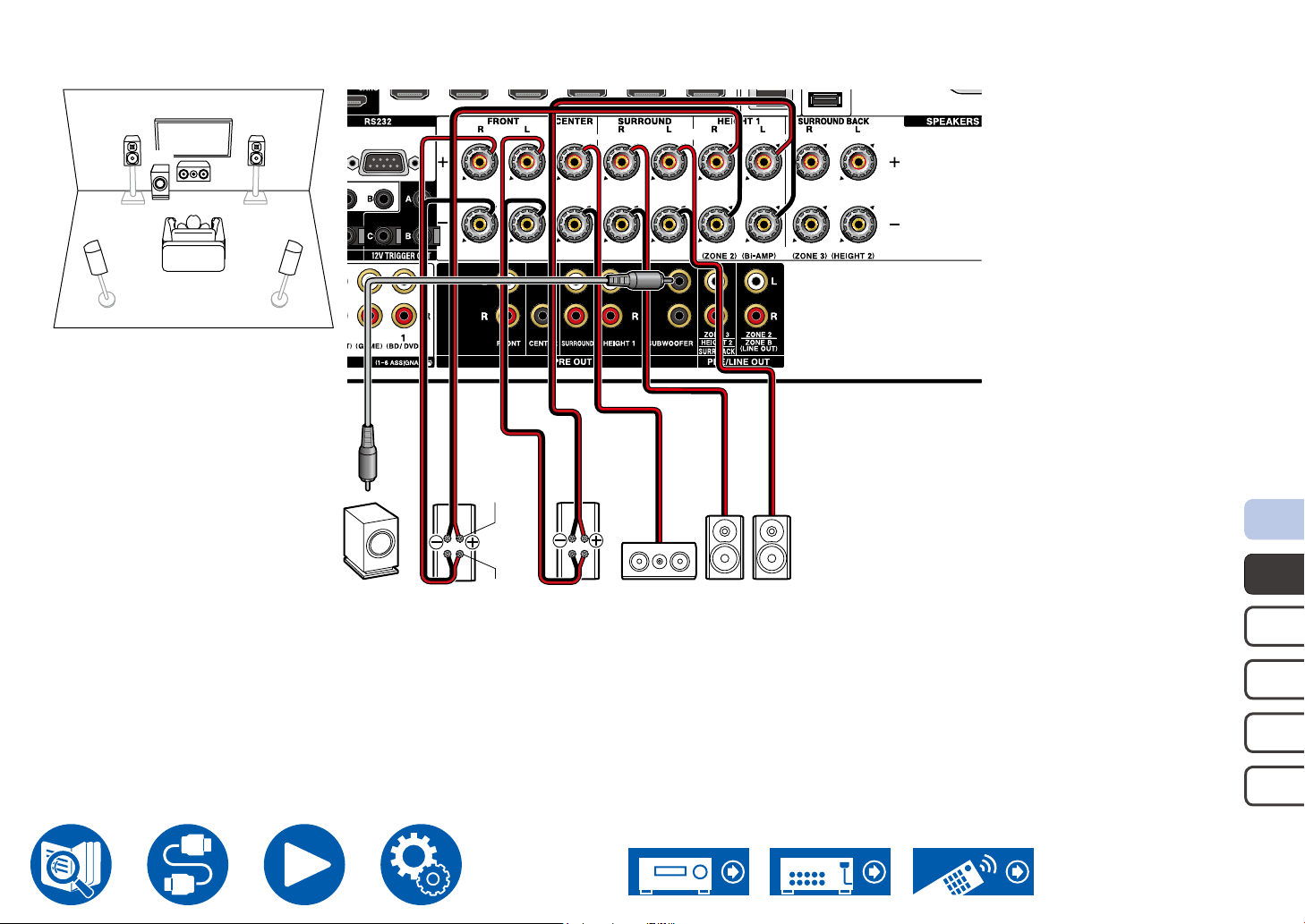
5.1 Channel System (Bi-Amping the Speakers)
FL FR
SW
SL SR
C
For highfrequency
Speaker Connections
SW
Be sure to remove the jumper bar connecting between the woofer jacks and tweeter jacks of the Bi-Amping supported speakers. Refer to the instruction manual of
your speakers as well.
FR
For lowfrequency
FL
C SR SL
5.1c h
7.1c h
5.1. 2ch
7.1. 2 c h
5.1.4ch
36
Page 37
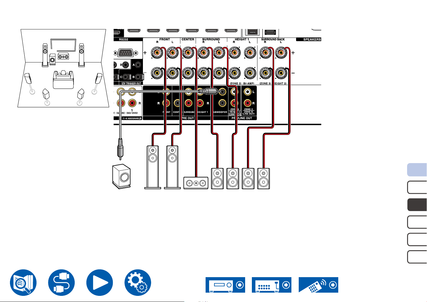
7.1 Channel System
FL FR
SW
SL SR
SBL SBR
C
Speaker Connections
SW FR FL C
5.1c h
SR SL SBR SBL
7.1c h
5.1. 2ch
7.1. 2 c h
5.1.4ch
37
Page 38
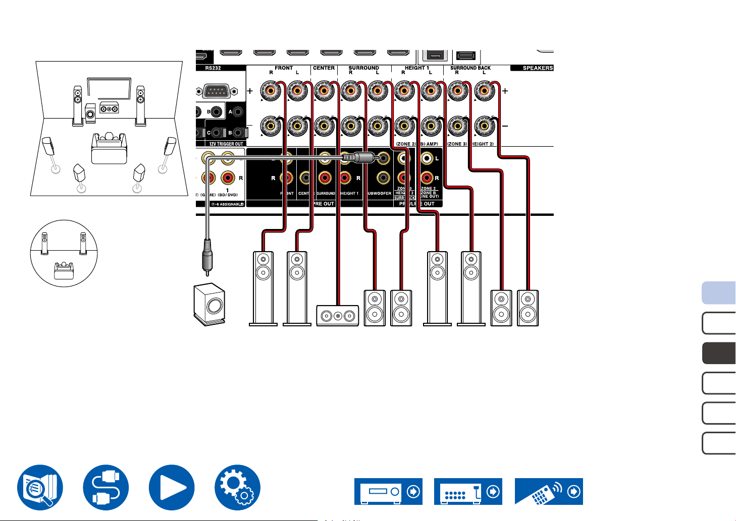
7.1 Channel System + ZONE SPEAKER
Main Room
FL FR
SW
SL SR
SBL SBR
Zone 2
FL(Z2)FR(Z2)
C
Speaker Connections
SW FR FL C SR SL FR(Z2) FL(Z2) SBR SBL
5.1c h
7.1c h
5.1. 2ch
7.1. 2 c h
5.1.4ch
38
Page 39
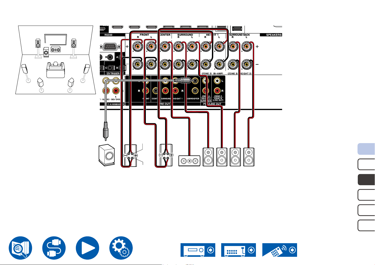
7.1 Channel System (Bi-Amping the Speakers)
FL FR
SW
SL SR
SBL SBR
C
For highfrequency
Speaker Connections
For low-
SW SBR SBL
Be sure to remove the jumper bar connecting between the woofer jacks and tweeter jacks of the Bi-Amping supported speakers. Refer to the instruction manual of
your speakers as well.
FR
frequency
FL
C SR SL
5.1c h
7.1c h
5.1. 2ch
7.1. 2 c h
5.1.4ch
39
Page 40
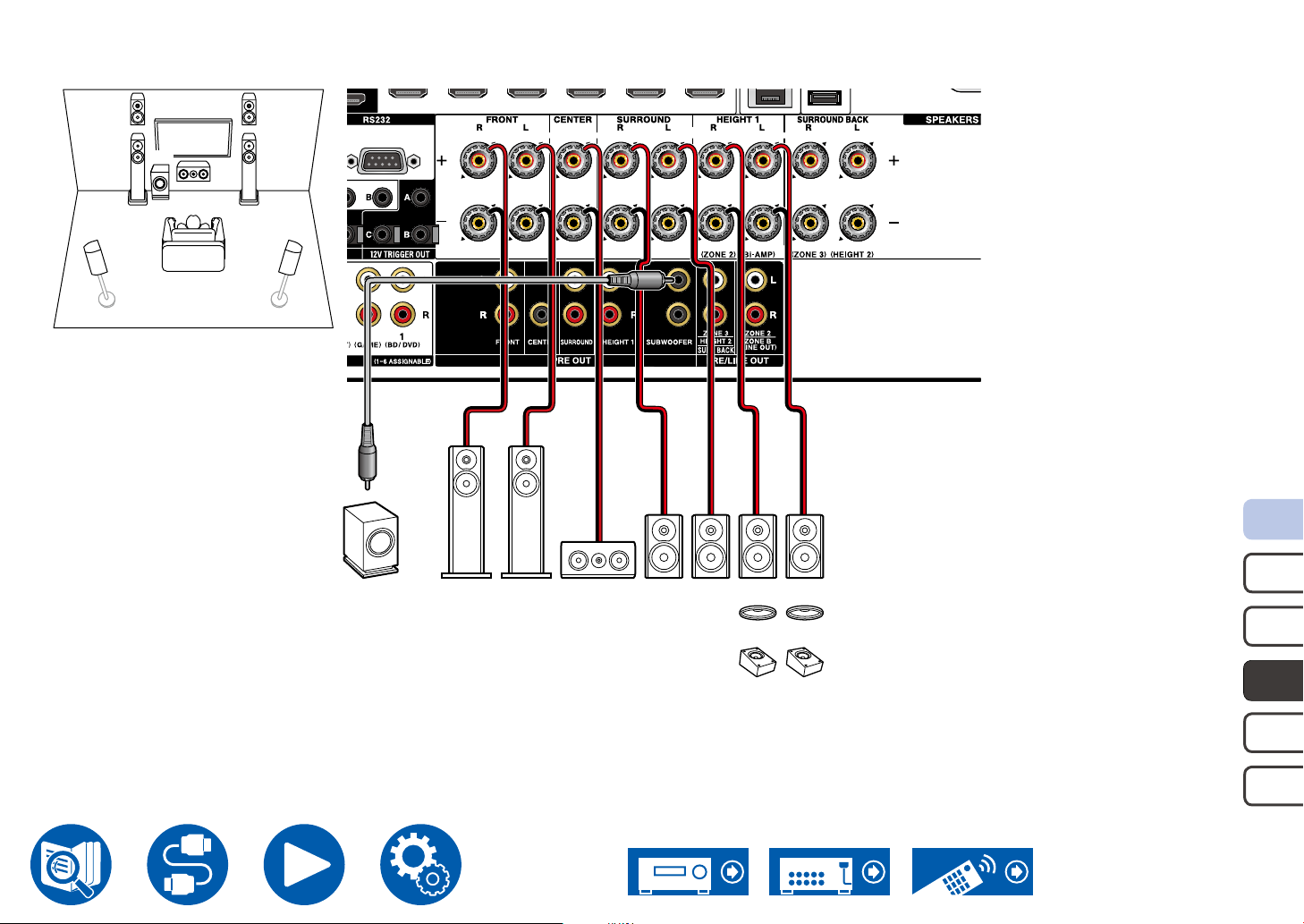
5.1.2 Channel System
HL HR
FL FR
SW
SL SR
C
Speaker Connections
OR
OR
HR
OR
OR
HL
SW FR FL C
SR SL
*1
*1 Connect the Height Speakers you have actually installed (HL/HR: Height Speakers, Top Speakers, Dolby Enabled Speakers).
5.1c h
7.1c h
5.1. 2ch
7.1. 2 c h
5.1.4ch
40
Page 41
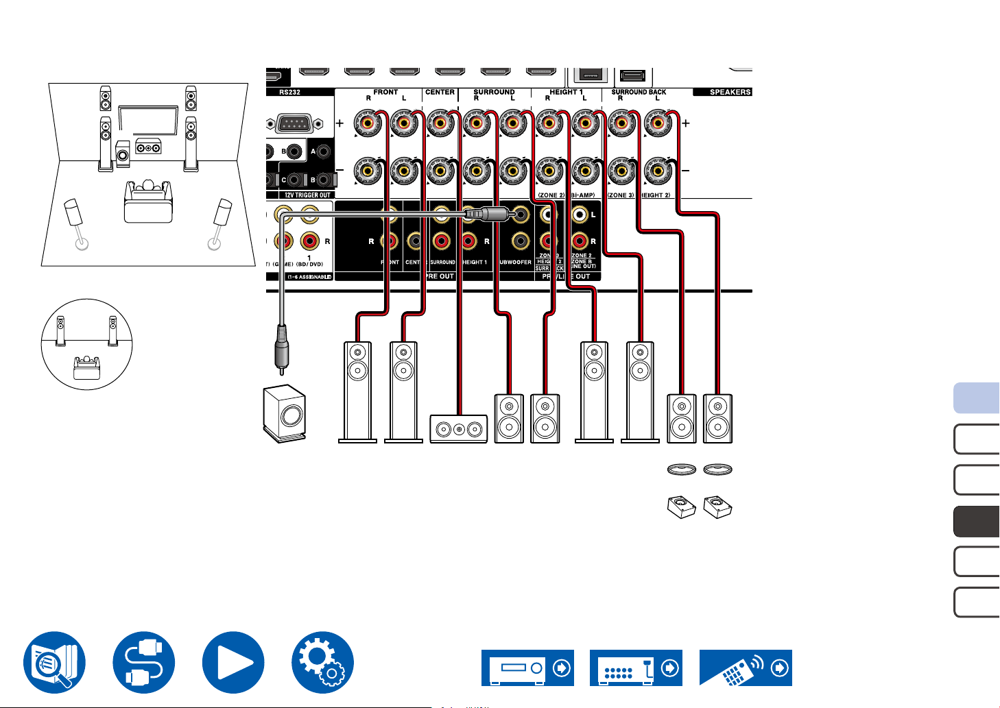
5.1.2 Channel System + ZONE SPEAKER
Main Room
HL HR
FL FR
SW
SL SR
Zone 2
FL(Z2)FR(Z2)
C
Speaker Connections
OR
SW FR FL C
SR SL
FR(Z2) FL(Z2)
OR
OR
HR
OR
HL
*1
*1 Connect the Height Speakers you have actually installed (HL/HR: Height Speakers, Top Speakers, Dolby Enabled Speakers).
5.1c h
7.1c h
5.1. 2ch
7.1. 2 c h
5.1.4ch
41
Page 42
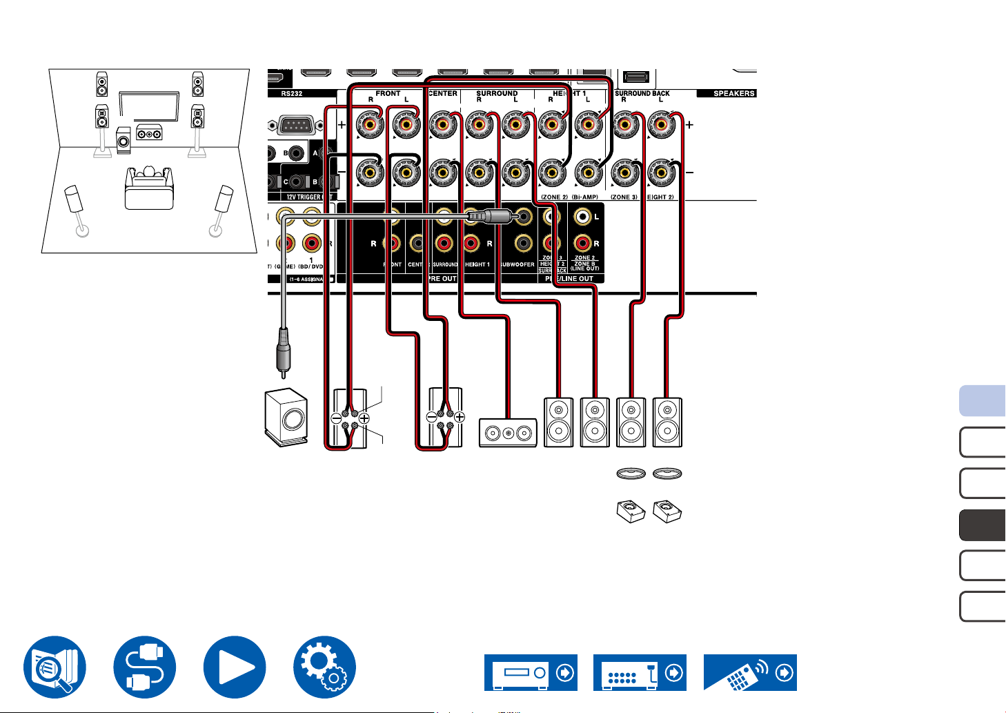
5.1.2 Channel System (Bi-Amping the Speakers)
HL HR
FL FR
SW
C
SRSL
For highfrequency
Speaker Connections
SW
FR
For lowfrequency
FL
C
SR SL
OR
OR
HR
OR
OR
HL
*1
Be sure to remove the jumper bar connecting between the woofer jacks and tweeter jacks of the Bi-Amping supported speakers. Refer to the instruction manual of
your speakers as well.
*1 Connect the Height Speakers you have actually installed (HL/HR: Height Speakers, Top Speakers, Dolby Enabled Speakers).
5.1c h
7.1c h
5.1. 2ch
7.1. 2 c h
5.1.4ch
42
Page 43
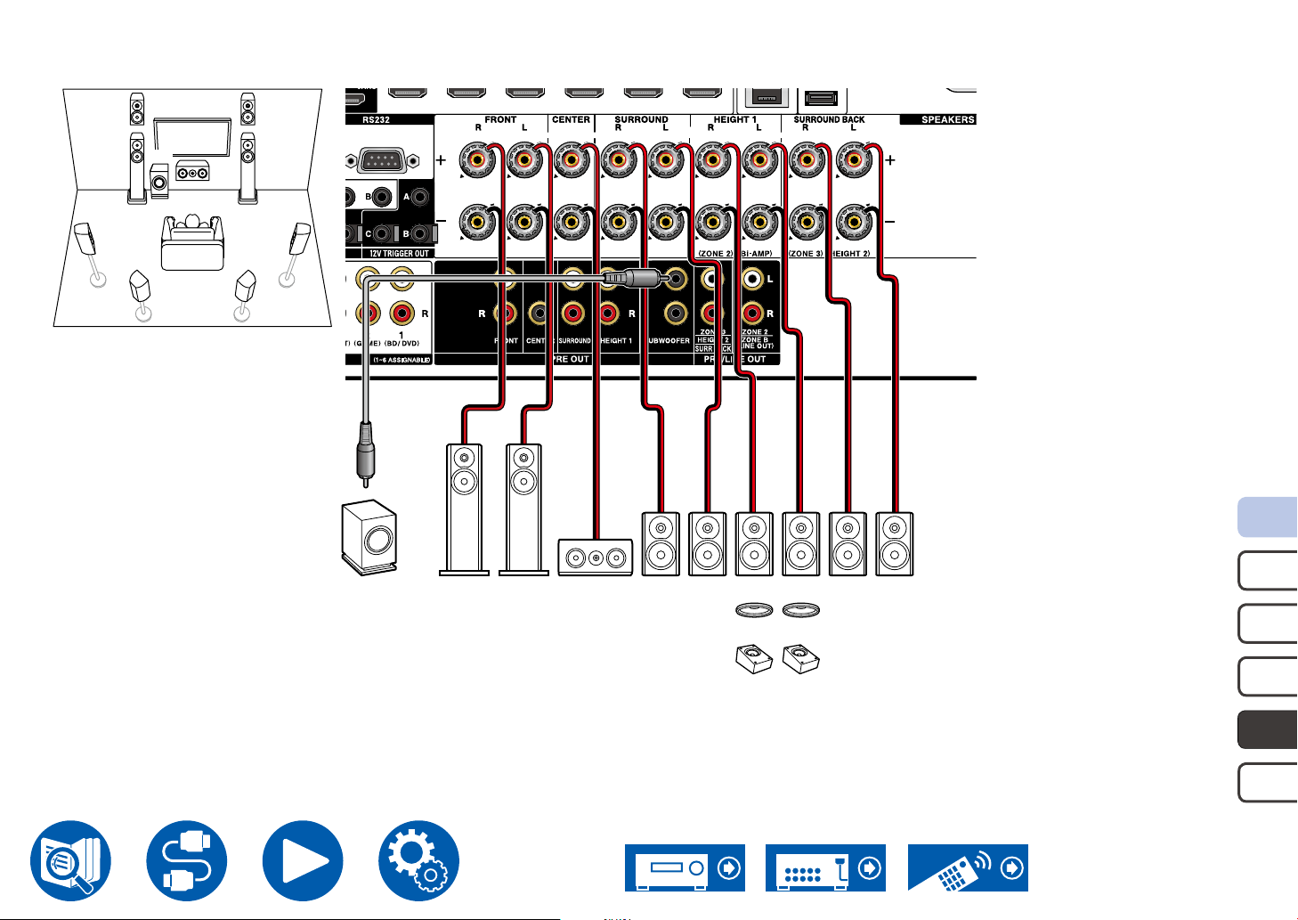
7.1.2 Channel System
HRHL
FL FR
SW
SL SR
SBL SBR
C
Speaker Connections
OR
OR
HR
OR
OR
HL
SBR SBL
SW FR FL C
SR SL
*1
*1 Connect the Height Speakers you have actually installed (HL/HR: Height Speakers, Top Speakers, Dolby Enabled Speakers).
5.1c h
7.1c h
5.1. 2ch
7.1. 2 c h
5.1.4ch
43
Page 44
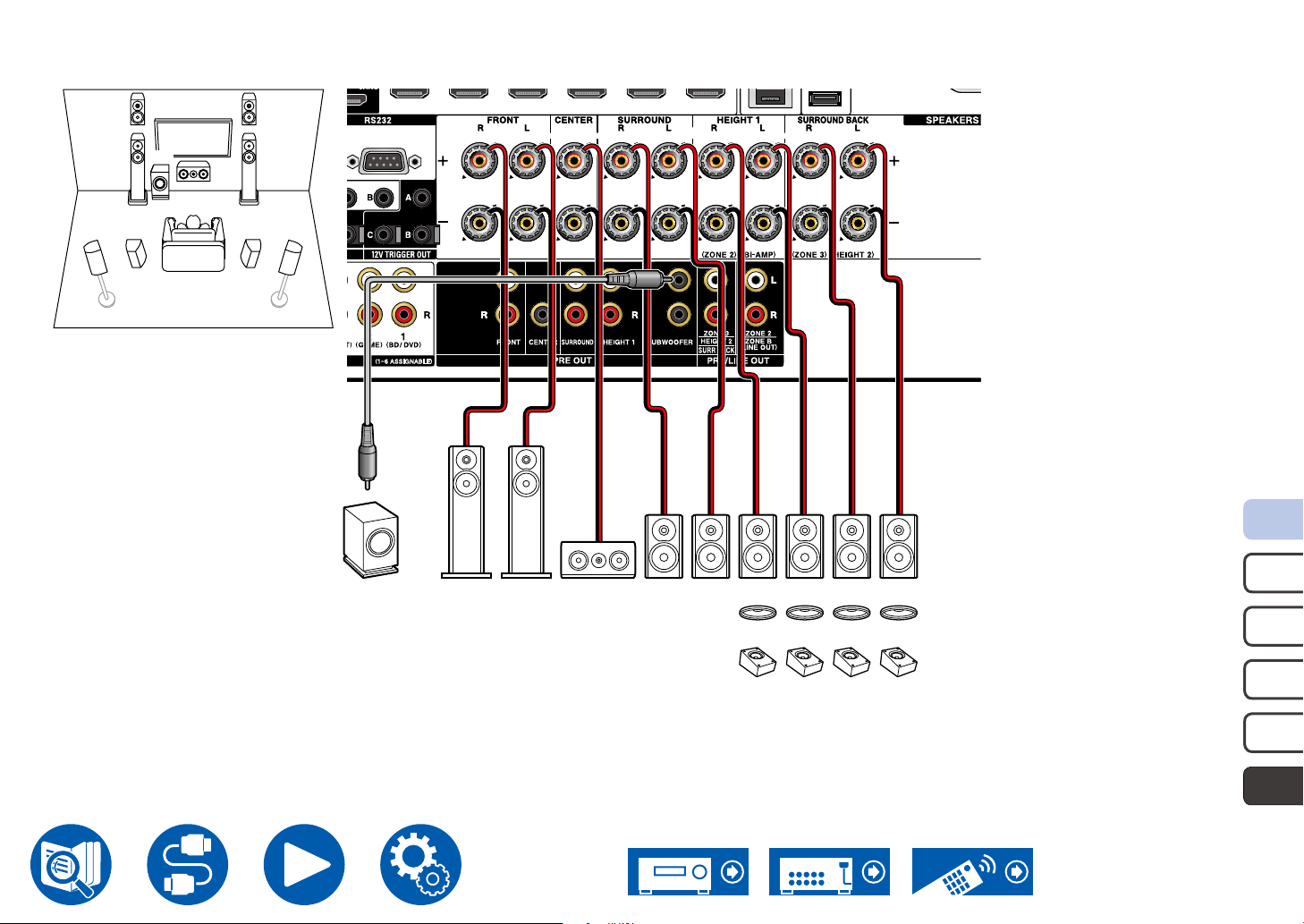
5.1.4 Channel System
HL1 HR1
FL FR
SW
SL SR
SL SR
C
HR2HL2
Speaker Connections
OR
OR
OR
OR
HR2
OR
OR
HL2
SW FR FL C
SR SL
OR
HR1
OR
HL1
*1 *2
*1 Connect the Height Speakers you have actually installed (HL1/HR1: Front Height Speakers, Top (front side) Speakers, Dolby Enabled Speakers (Front)).
*2 Connect the Height Speakers you have actually installed (HL2/HR2: Rear Height Speakers, Top (rear side) Speakers, Dolby Enabled Speakers (Surround)).
5.1c h
7.1c h
5.1. 2ch
7.1. 2 c h
5.1.4ch
44
Page 45
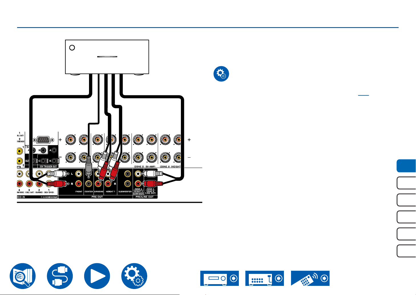
Connecting a Power Amplier
Speaker Connections
Power amplier
a
You can connect a power amplier to the unit and use the unit as a pre-amplier
in order to produce a large volume that cannot be output with the unit only.
Connect the speakers to the power amplier. For details, refer to the power
amplier's instruction manual.
• Use the PRE OUT jacks for connection as show on the left.
Setup
• Set "2. Speaker" - "Conguration" - "Speaker Channels" ( →p112) according
to the number of channels of the connected speakers.
5.1c h
7.1c h
a Analog audio cable
5.1. 2ch
7.1. 2 c h
5.1.4ch
45
Page 46
Connections
Notes regarding connections with HDMI cables 47
Connecting the TV 48
Connecting the SUB Monitor 49
Connecting Playback Devices 50
Connecting a TV or Integrated Amplier in a
separate room (Multi-zone) 54
Connecting Antennas 57
Connections
Network Connection 58
Connecting External Control Devices 59
Connecting the Power Cord 61
46
Page 47
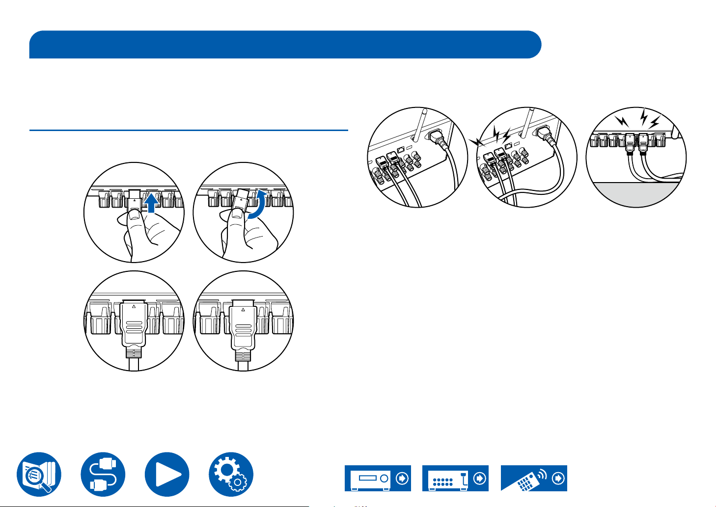
Notes regarding connections with HDMI cables
Connections
HDMI (High-Denition Multimedia Interface) is a digital interface standard for
connecting TVs, projectors, Blu-ray Disc players, game consoles, and other
video components. With HDMI, a single cable can carry control signals, digital
video, and digital audio.
Connections
Push HDMI cables straight in and all the way. You can damage the terminals if
you try to insert at an angle.
Right
Right Wrong
Wrong
(Note) Placement of cables
Putting a load on HDMI cables can lead to poor operational performance. Place
the cables so there is no load put on them.
Right Wrong Wrong
• When 4K high-quality video (4K 60Hz, 4K HDR, etc.) is to be played, use
Premium High Speed HDMI Cable or Premium High Speed HDMI Cable
with Ethernet that have the "PREMIUM Certied Cable" label attached to the
packaging.
• When 8K high-quality video (8K 60Hz, etc.) is to be played, use ULTRA High
Speed HDMI Cable that has the "ULTRA HIGH SPEED" label attached to the
packaging.
• Hold the terminal housing on the HDMI cable when unplugging. Pulling on the
cable may lead to damaged cabling.
47
Page 48
Connections
DIGITAL
OPTICAL
OUT
IN(ARC)
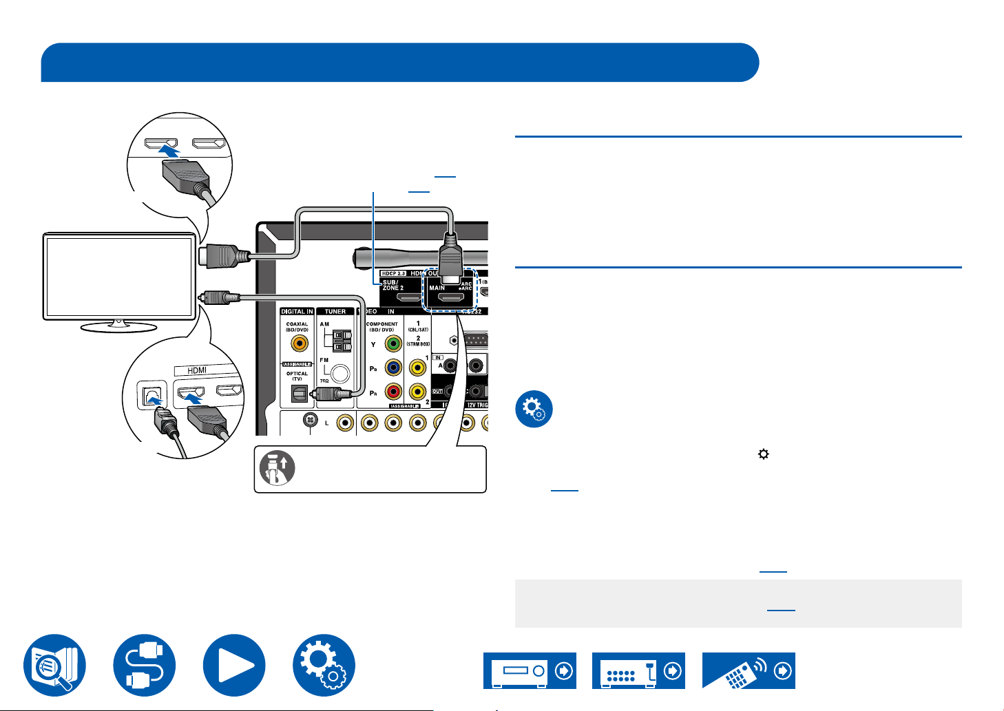
Connecting the TV
By connecting a TV to this unit, you can show the video from AV devices connected to this unit on the TV and also play the sound from the TV through this unit.
To ARC/eARC TV
If the TV supports the ARC (Audio Return Channel) function(*), use only the
HDMI cable to connect with the TV. Use the ARC-compatible HDMI IN jack of
the TV for connection. You connect the HDMI cable to the HDMI OUT MAIN jack
labeled "ARC" on the receiver side.
• When a TV compatible with the eARC function is connected, use an HDMI
cable that supports Ethernet.
ARC TV
SUB Monitor ( →p49)
ZONE 2 ( →p54)
a
To Non-ARC TV
If the TV does not support the ARC (Audio Return Channel) function(*), connect
b
TV
an HDMI cable and digital optical cable. If the TV does not have a DIGITAL
OPTICAL OUT jack, you can use an analog audio cable to connect with the
AUDIO IN TV jack.
• If you use a cable set-top box, etc. connected to the input jack of this unit to
watch TV (without using a TV’s built-in tuner), connection with a digital optical
cable or analog audio cable is not required.
Non-ARC TV
a HDMI cable, b Digital optical cable
Be sure to insert the HDMI
cable all the way in.
Setup
• When not using the ARC function, press on the remote controller, then
set "6. Hardware" - "HDMI" - "Audio Return Channel (eARC supported)"
( →p125) to "Off".
(*)The ARC function and eARC function transmit the audio signals of the TV via
an HDMI cable, and plays the audio of the TV on this unit. To check if the TV
supports the ARC function and eARC function, refer to the instruction manual
of the TV, etc.
ARC/eARC compatible audio formats ( →p184)
• Settings are required when 4K or 8K high-quality video is to be played.
Refer to "HDMI 4K/8K Signal Format" ( →p108) for information on the
settings. Also, use an HDMI cable that supports 4K or 8K video.
48
Page 49
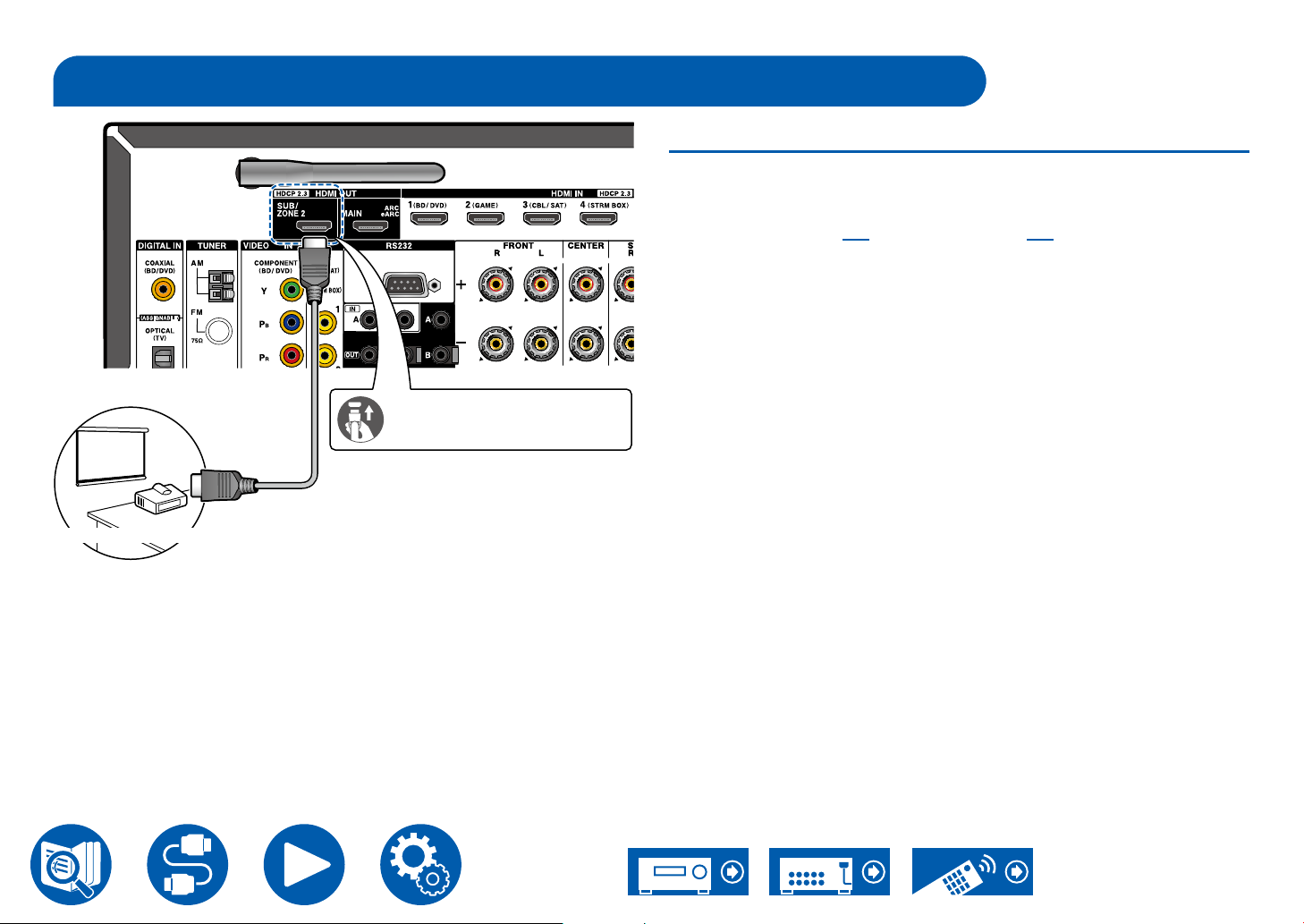
Connecting the SUB Monitor
Be sure to insert the HDMI
cable all the way in.
a
SUB Monitor
Connections
SUB Monitor
This unit has multiple HDMI OUT jacks, and another TV or projector can be
connected to the HDMI OUT SUB jack.
• Switch between MAIN and SUB using the HDMI Main/Sub button on the
remote controller ( →p15) or "Quick Menu" ( →p73). Note that this jack
is not ARC-compatible.
• If devices with different resolutions are connected to HDMI OUT MAIN jack
and SUB jack, images are output with the lower resolution.
a HDMI cable
49
Page 50
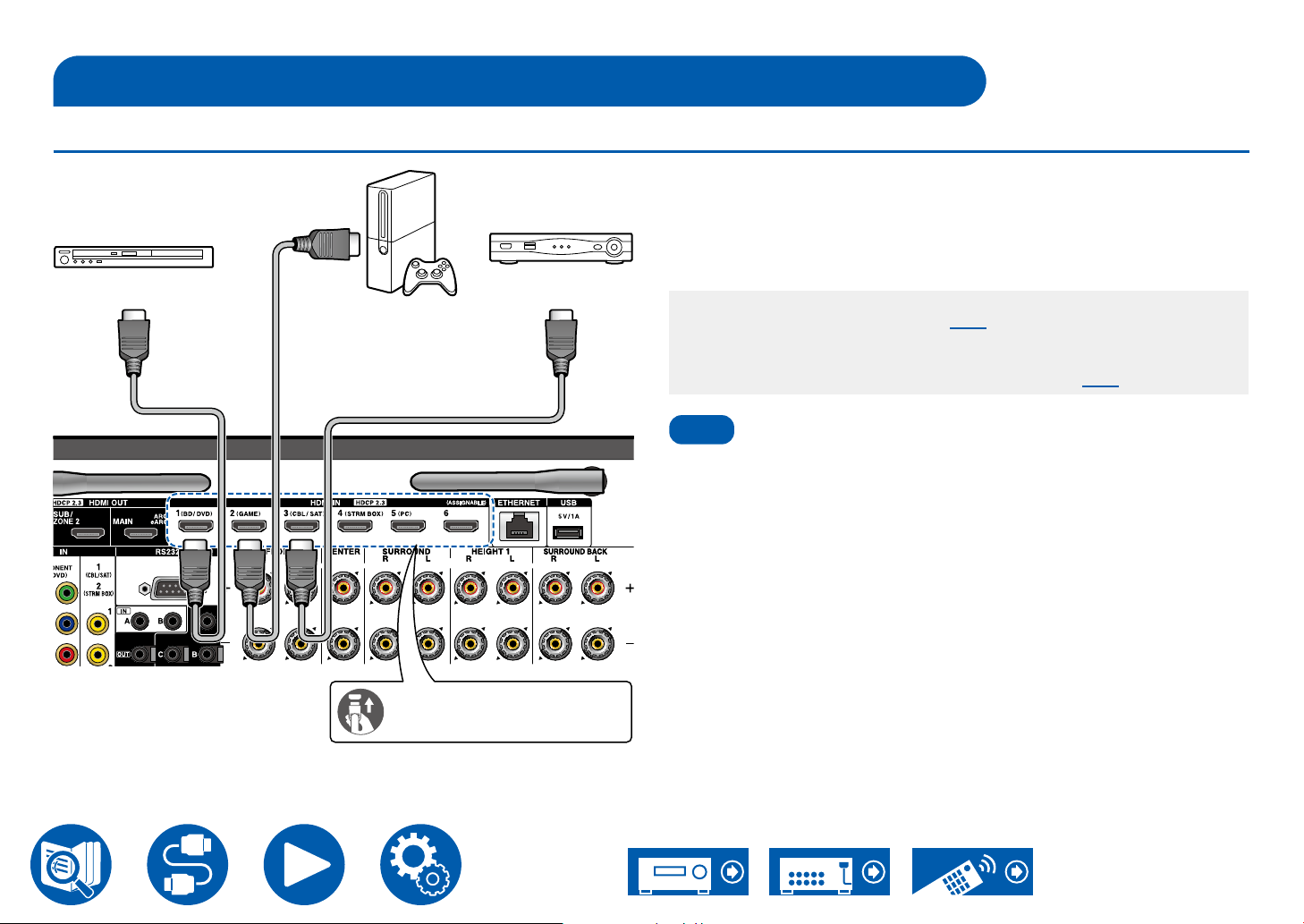
Connecting Playback Devices
a
Note
Connections to BD/DVD and GAME with HDMI jacks
This is a connection example of an AV component equipped with an HDMI jack.
When connecting with an AV component that conforms to the CEC (Consumer
Electronics Control) standard, you can use the HDMI CEC function (*) that
enables linking with input selectors, etc. and the HDMI Standby Through
function that can transmit video and audio signals of the AV component to the
BD/DVD
GAME
Cable/Satellite
set-top box
TV even if this unit is in standby mode.
• Settings are required when 4K or 8K high-quality video is to be played. Refer
to "HDMI 4K/8K Signal Format" ( →p108) for information on the settings.
Also, use an HDMI cable that supports 4K or 8K video.
• The corresponding resolution is different depending on the HDMI jack
connected. See "Corresponding input resolutions" ( →p185) for details.
• To enjoy digital surround sound including Dolby Digital, set the audio output of
the connected Blu-ray Disc player etc. to the Bitstream output.
(*)The HDMI CEC function: This function enables various linking operations with
CEC-compliant devices, such as switching input selectors interlocking with
a CEC-compliant player, switching audio output between TV and this unit or
adjusting the volume using the remote controller of a CEC-compliant TV, and
automatically switching this unit to standby when the TV is turned off.
Connections
Be sure to insert the HDMI
cable all the way in.
a HDMI cable
50
Page 51
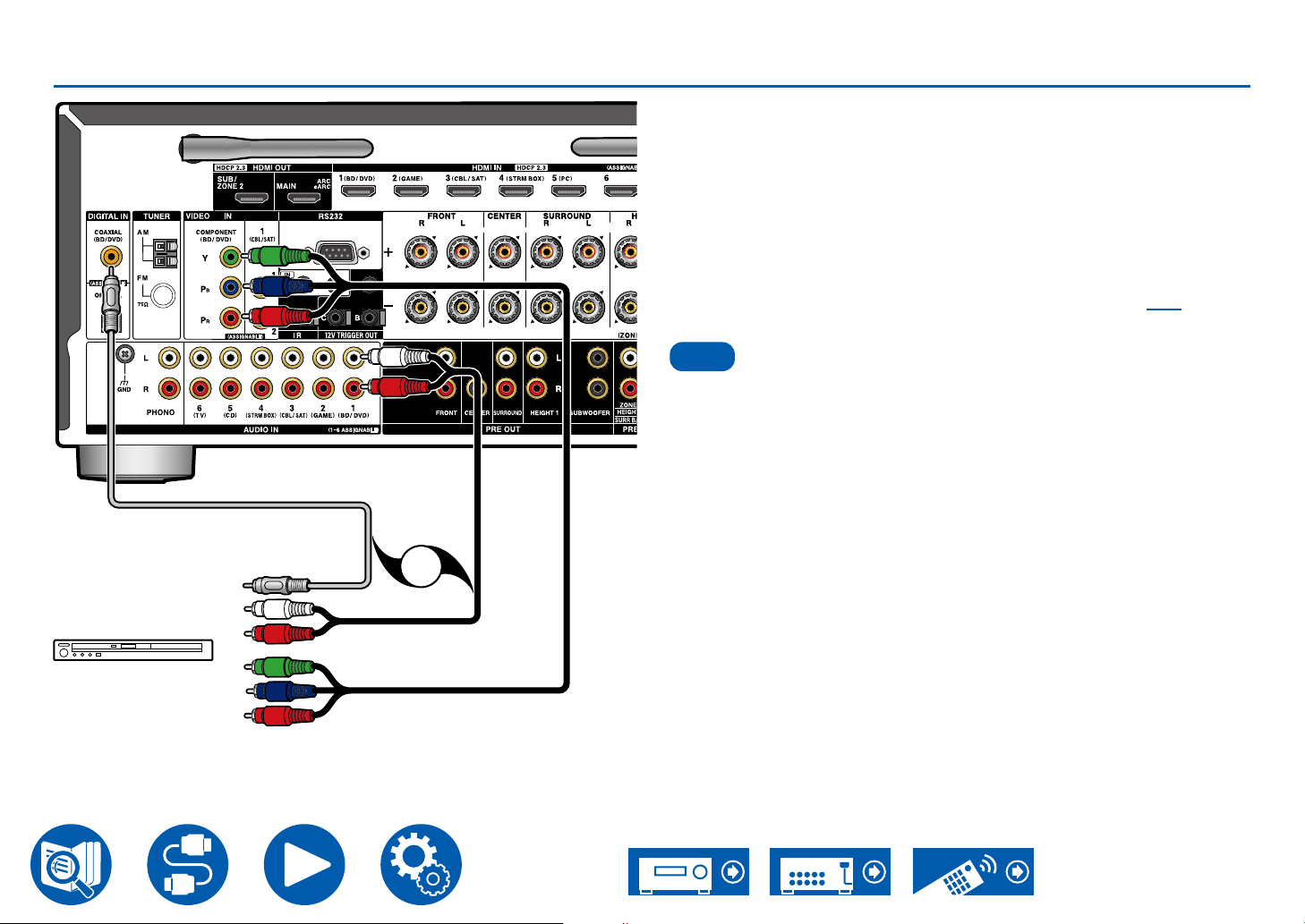
Connecting a BD/DVD without HDMI Jack Mounted
Note
a
c
OR
b
This is a connection example of an AV component unequipped with an HDMI
jack. Select cables that match the jacks of the AV component for connection. For
example, when video input is connected to the BD/DVD jack, connect the audio
input to BD/DVD jack, too. Thus, video input jacks and audio input jacks should
have the same name for connection. Note that video signals input to the VIDEO
IN jack or the COMPONENT VIDEO IN jack are converted to HDMI video
signals, and then output from the HDMI OUT jack.
• To enjoy digital surround playback in formats such as Dolby Digital, you need
to make a connection for audio signals with a digital coaxial cable or a digital
optical cable.
• According to the illustration, changing the input assignment ( →p110)
enables connection to jacks other than the BD/DVD jack.
• The COMPONENT VIDEO IN jacks are compatible only with 480i or 576i
resolution. When connecting to the COMPONENT VIDEO IN jacks, set the
output resolution of the player to 480i or 576i. If there is no option such as
480i, select interlace. If your player does not support 480i or 576i output, use
the VIDEO IN jack.
• To enjoy digital surround sound including Dolby Digital, set the audio output of
the connected Blu-ray Disc player etc. to the Bitstream output.
Connections
BD/DVD
a Digital coaxial cable, b Analog audio cable, c Component video cable
51
Page 52
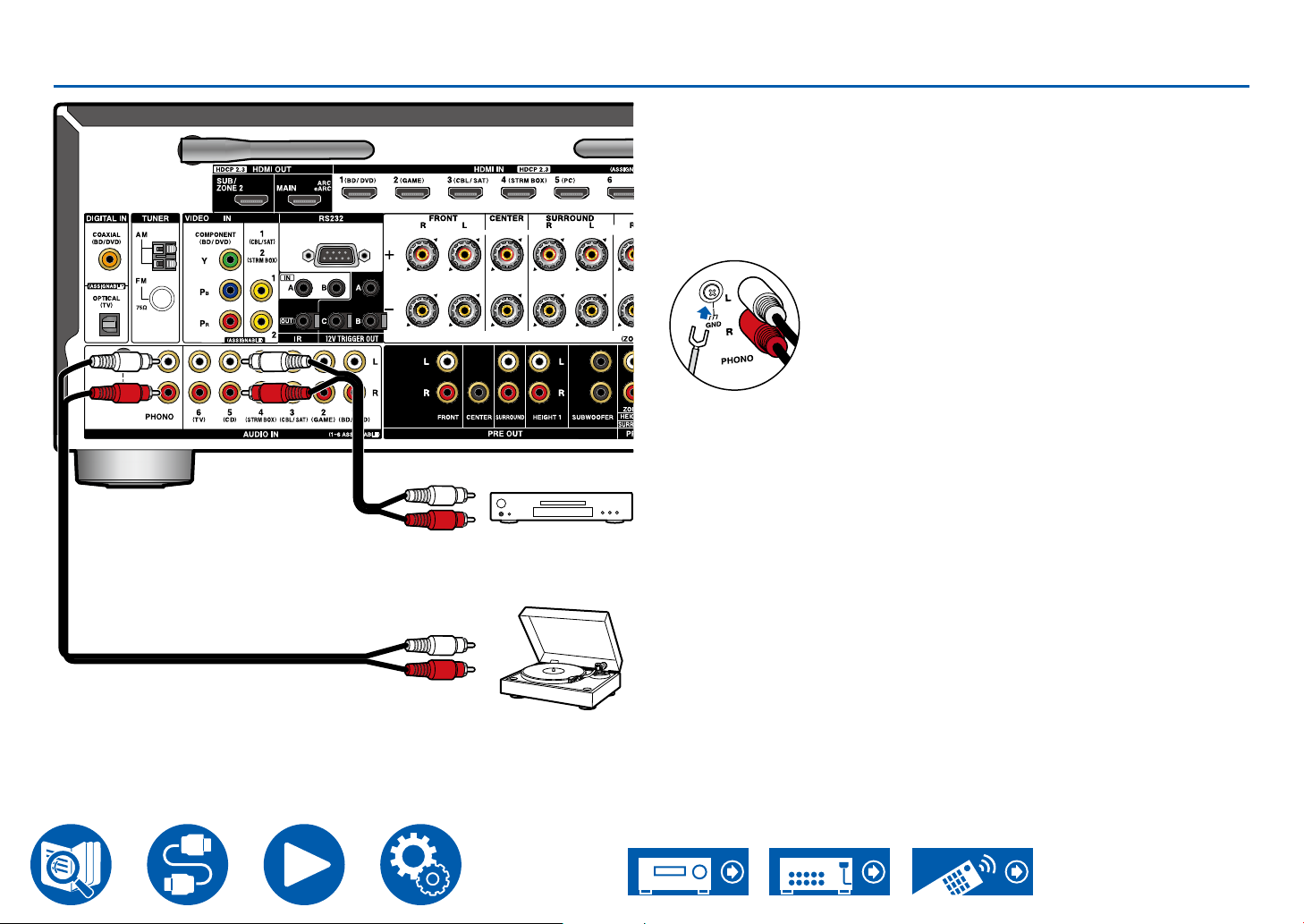
Connecting an Audio Component
a
Connections
This is a connection example of an audio component. Connect a CD player
using an analog audio cable. You can also connect a turntable that has an MMtype cartridge to the PHONO jack.
• If the turntable has a built-in phono equalizer, connect it to any of the AUDIO
IN jacks other than the PHONO jack. Further, if the turntable uses an MC type
cartridge, install a phono equalizer compatible with the MC type cartridge
between the unit and the turntable, and then connect it to any of the AUDIO
IN jacks other than the PHONO jack.
If the turntable has a ground wire, connect it to the GND terminal of this unit.
CD
a
a Analog audio cable
Turntable
52
Page 53
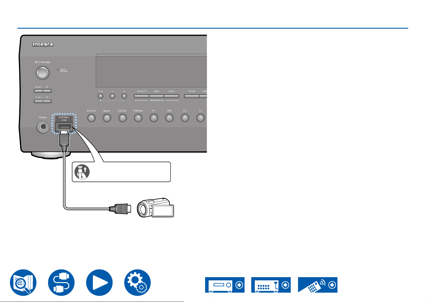
Connecting a Video Camera, etc.
Be sure to insert the HDMI
cable all the way in.
Connections
Connect a video camera, etc. to the AUX Input HDMI jack on the front panel
using an HDMI cable.
a HDMI cable
a
Video camera
53
Page 54
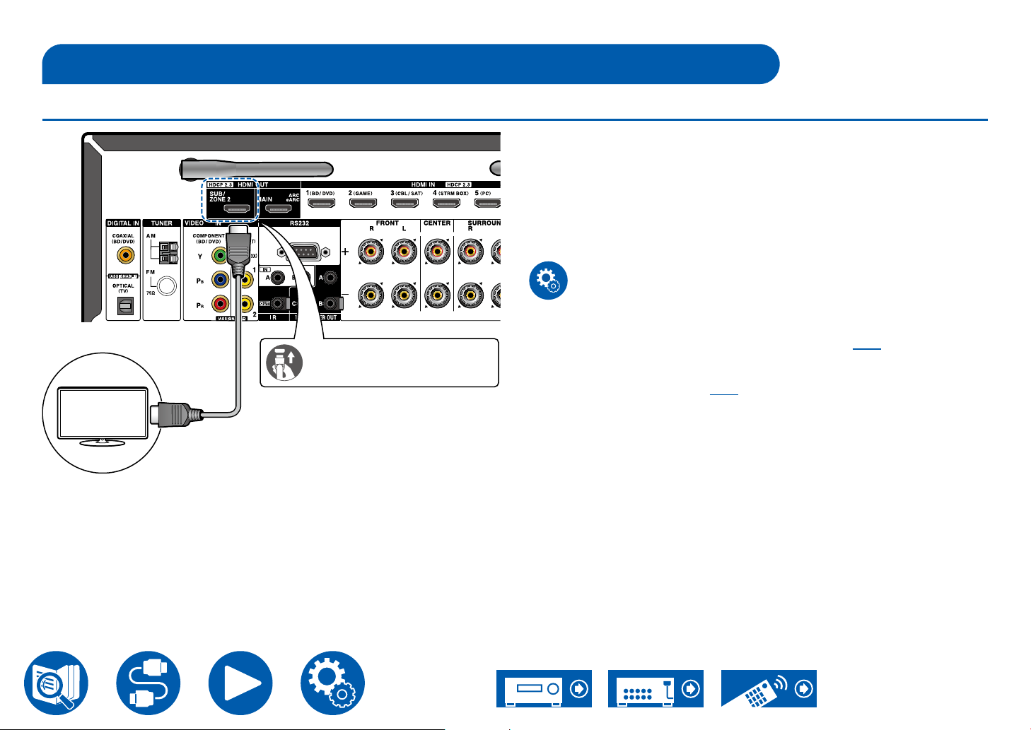
Connecting a TV or Integrated Amplier in a separate room (Multi-zone)
Connecting a TV (ZONE 2)
While a disc is played on a Blu-ray Disc player in the main room (where this unit
is located), you can play the video and audio of the same Blu-ray Disc player or
another AV component on the TV equipped with an HDMI IN jack in a separate
room (Zone 2). Note that only the devices connected to the HDMI IN1 to IN3
jacks can be played on the TV in the separate room.
• Audio from an externally connected AV component can be output only
when the audio is 2 ch PCM audio signal. Also, the audio output of the AV
component may need to be changed to the PCM output.
Setup
• When video and audio via HDMI input are output to ZONE 2, set "1. Input/
Output Assign" - "TV Out / OSD" - "Zone 2 HDMI" ( →p108) to "Use" on the
Be sure to insert the HDMI
a
cable all the way in.
Setup menu. Note that when "Zone 2 HDMI" is set to "Use", the resolution
of the video that can be output by the HDMI OUT SUB/ZONE 2 jack will be
limited to "4K Enhanced" ( →p108).
Connections
TV
a HDMI cable
54
Page 55
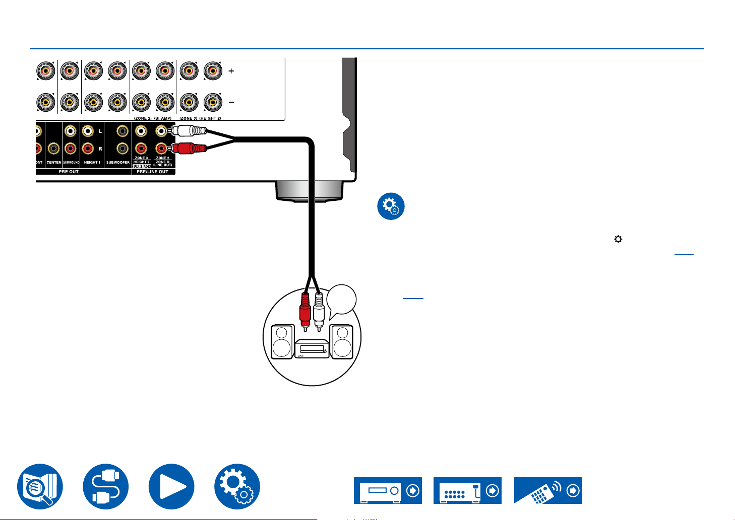
Connecting an Integrated Amplier (ZONE 2)
Connections
You can enjoy 2 ch audio in the separate room (Zone 2) while performing
playback in the main room (where this unit is located). Use an analog audio
cable to connect the ZONE 2 PRE/LINE OUT jacks on this unit to the input jack
on an integrated amplier in the separate room.
• To output audio from an externally connected AV component to ZONE 2,
connect it to any of HDMI IN1 to IN3 jacks. If the AV component is not
equipped with an HDMI jack, use a digital coaxial cable, digital optical
cable or analog audio cable. Also, the audio from externally connected AV
components can be output to ZONE 2 only when the audio is analog or 2 ch
PCM signal. When the AV component is connected to this unit with a digital
coaxial cable or digital optical cable, change the audio output of the AV
component to the PCM output.
a Analog audio cable
a
Integrated
amplier
Input
Terminal
Setup
• Settings are required to output audio to ZONE 2. Press on the remote
controller, and set "2. Speaker" - "Conguration" - "Zone 2 Preout" ( →p113)
to "Zone 2".
• When connecting an integrated amplier that does not have a volume
control, in the Setup menu, set "7. Multi Zone" - "Zone 2" - "Output Level"
( →p137) to "Variable" (Default Value: Fixed). If it is not set, a large volume
is output and the integrated amplier, speakers, etc. may be damaged. When
connecting an integrated amplier that has a volume control, leave this as
"Fixed".
55
Page 56
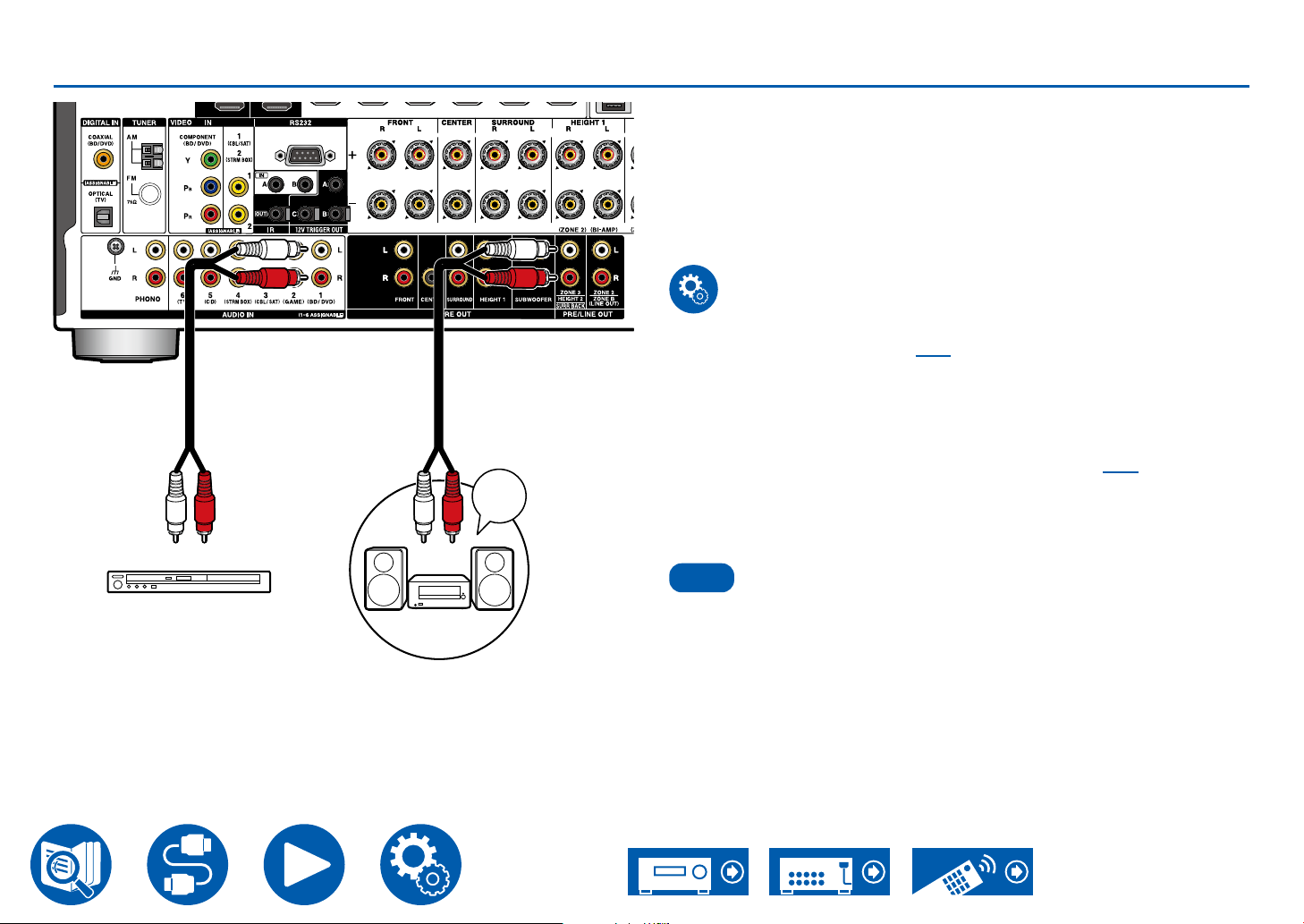
Connecting an Integrated Amplier (ZONE 3)
Note
a a
Input
Terminal
Connections
You can enjoy 2 ch audio in the separate room (Zone 3) while performing
playback in the main room (where this unit is located). Use an analog audio
cable to connect the ZONE 3 PRE/LINE OUT jacks on this unit to the input jack
on an integrated amplier in the separate room.
• To output audio from an externally connected AV component to ZONE 3,
use an analog audio cable for connection. Note that ZONE 3 output is not
possible with the connection using a HDMI cable, digital coaxial cable, or
digital optical cable.
Setup
• With speaker combinations ( →p181) 2.1.2 ch, 3.1.2 ch, 4.1.2 ch, or 5.1.2
ch, this function cannot be used when using Bi-AMP or ZONE 2 (ZONE
SPEAKER). However, when a power amplier without a volume control is
connected to the ZONE 3 PRE/LINE OUT terminals, it is possible to use
ZONE 2 (ZONE SPEAKER) and ZONE 3 (ZONE SPEAKER).
• When connecting an integrated amplier that has an external volume
control, set "7. Multi Zone" - "Zone 3" - "Output Level" ( →p137) to "Fixed
(Default Value)" on the Setup menu. If your external amplier does not have
an external volume control please set this at "Variable". If you do not set this,
the volume output will be very loud and there is a danger of damage to the
integrated amplier, speakers, etc.
a Analog audio cable
BD/DVD
Integrated
amplier
• ZONE 3 PRE/LINE OUT cannot be used when the connected speaker
conguration is "6.1 ch", "7.1 ch", "6.1.2 ch", "7.1.2 ch", "4.1.4 ch", or "5.1.4 ch".
56
Page 57
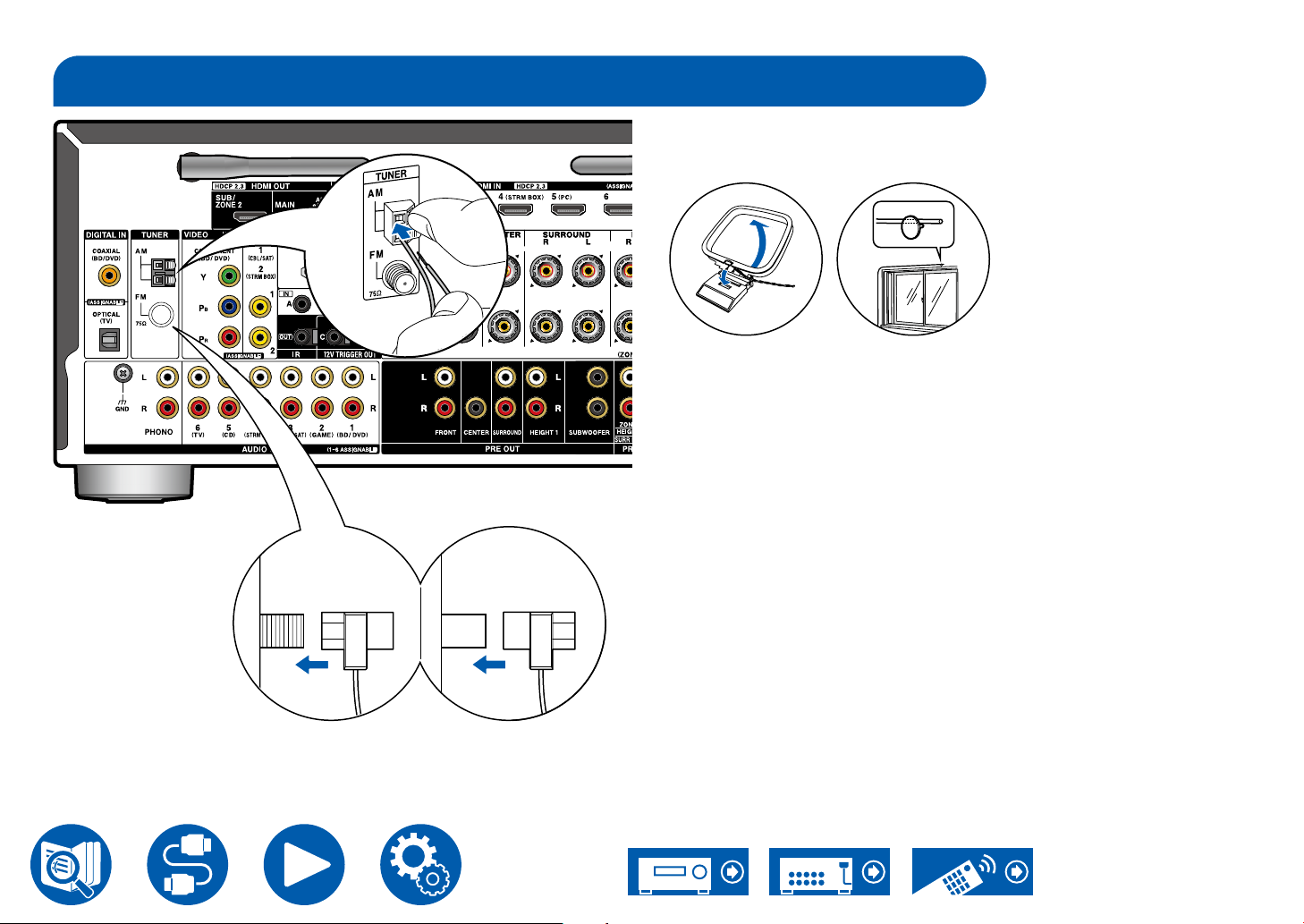
Connecting Antennas
b
b
A B
Connections
Connect the antenna to this unit, and set up the antenna at the best position for
listening while receiving radio signals. Attach the indoor FM antenna to the wall
using push pins or adhesive tape.
AMAM
a
FMFM
(North American
models)
b
(Australian models)
b
a
b
a AM loop antenna, b Indoor FM antenna
57
Page 58
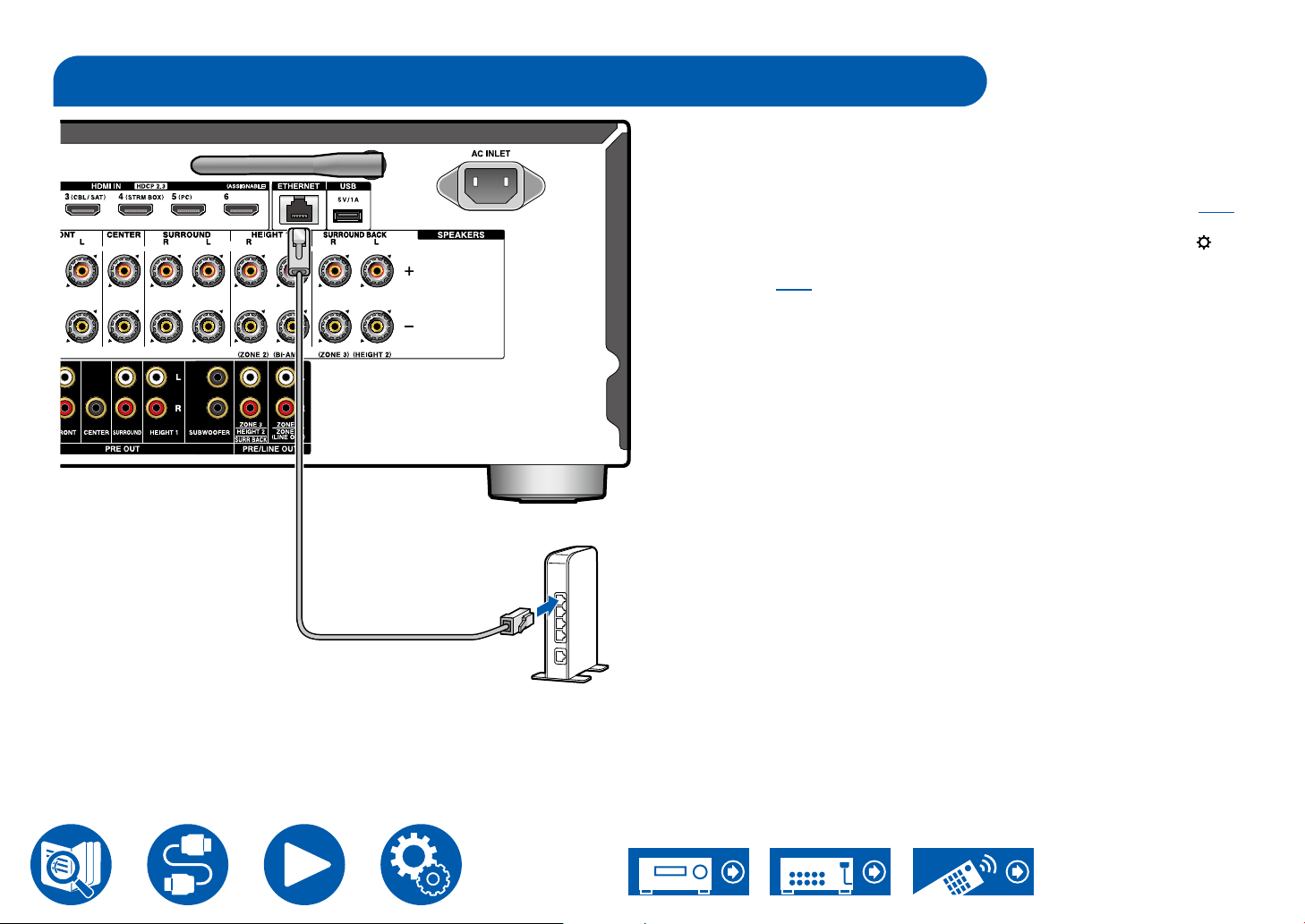
Network Connection
Connections
This unit can be connected to the network using a wired LAN or Wi-Fi (wireless
LAN). You can enjoy network functions such as Internet radio by network
connection. If connection is made by the wired LAN, connect the router and the
ETHERNET jack with the Ethernet cable as shown in the illustration. To connect
by Wi-Fi, select your desired setting method in "Network Connection" ( →p143)
of Initial Setup, and then follow the on-screen instructions. To congure the
setting on the Setup menu after the completion of Initial Setup, press the
button on the remote controller, and select "6. Hardware" - "Network" to make
the setting ( →p126). For the Wi-Fi connection, stand the wireless antenna for
use.
a Ethernet cable
a
Router
58
Page 59
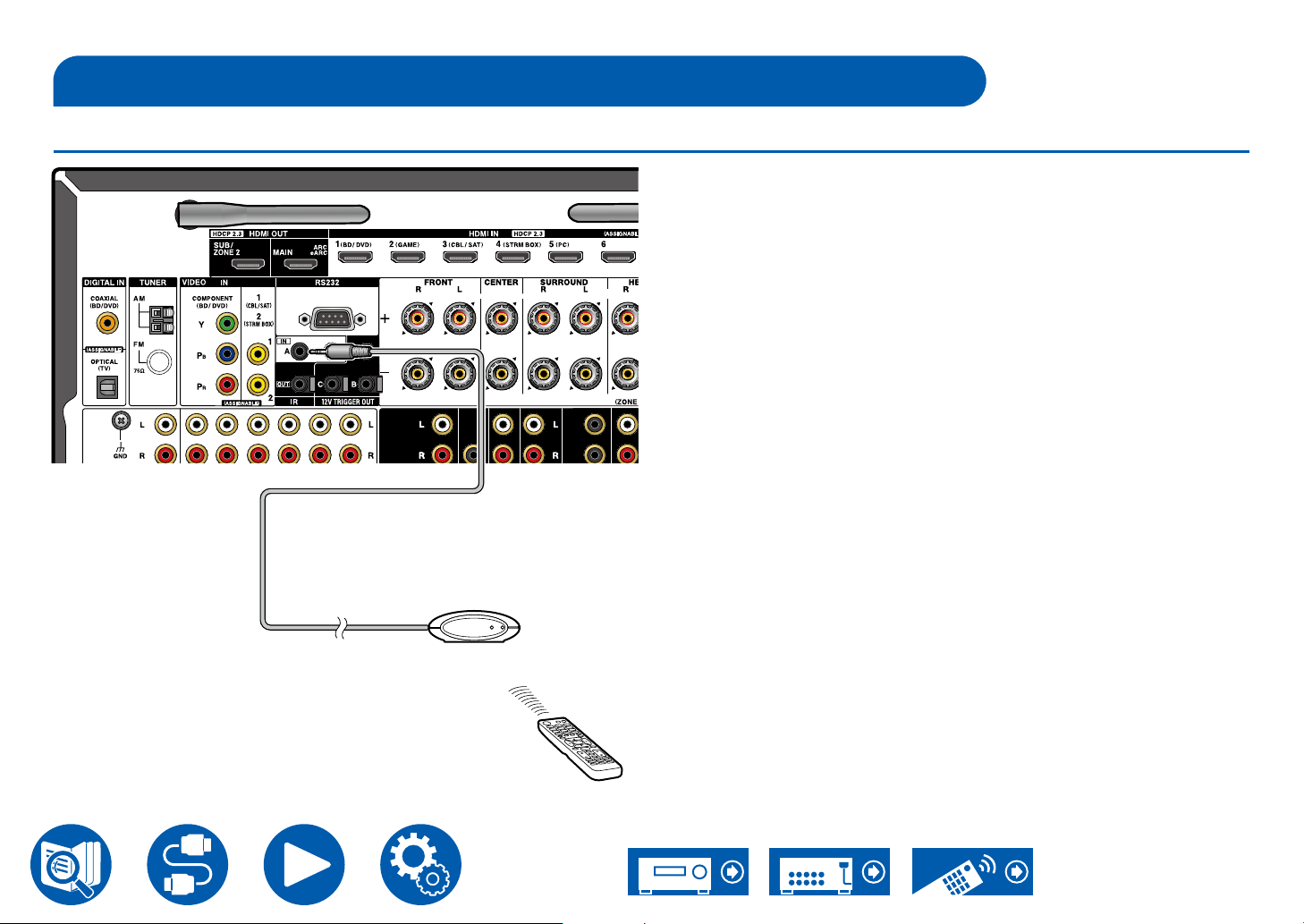
Connecting External Control Devices
IR IN/OUT port
Connections
When connecting a remote control receiver unit consisting of an IR Receiver,
etc. to this unit, operation using the remote controller is possible even if the
remote control signal is difcult to reach (due to installation in the cabinet,
etc.). It is also possible to operate this unit from other room such as ZONE 2
with a remote controller, or operate other devices with the remote controller by
connecting other devices to this unit. For installing a remote control receiver unit,
contact the specialized stores.
• For the type of cable required for connection, refer to the operation manual,
etc. of the remote control receiver unit.
IR Receiver
59
Page 60
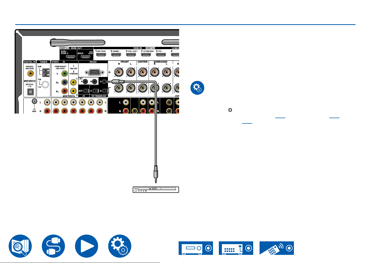
12V TRIGGER OUT jack
Connections
When connecting a device equipped with a TRIGGER IN jack such as a BD/
DVD player to this unit, the device can be turned on or set to standby by
interlocking the operation on this unit. When the desired input is selected on the
unit, power link operation will be activated with a control signal of maximum 12
V/100 mA from the 12V TRIGGER OUT A jack or maximum 12 V/25 mA when
using the 12V TRIGGER OUT B or C jack. You can select the zone to output the
control signal by setting each of the inputs.
• For connection, use a monaural mini plug cable (ø1/8″/3.5 mm) without
resistance. Do not use a stereo mini plug cable.
Setup
• Settings are required to output control signals from the 12 V TRIGGER OUT
jack. Press the button on the remote controller, select the input desired
for "6. Hardware" - "12V Trigger A" ( →p132), "12V Trigger B" ( →p133)
or "12V Trigger C" ( →p134), and set the output destination for the control
signal.
a Monaural mini plug cable (ø1/8″/3.5 mm)
a
BD/DVD
60
Page 61
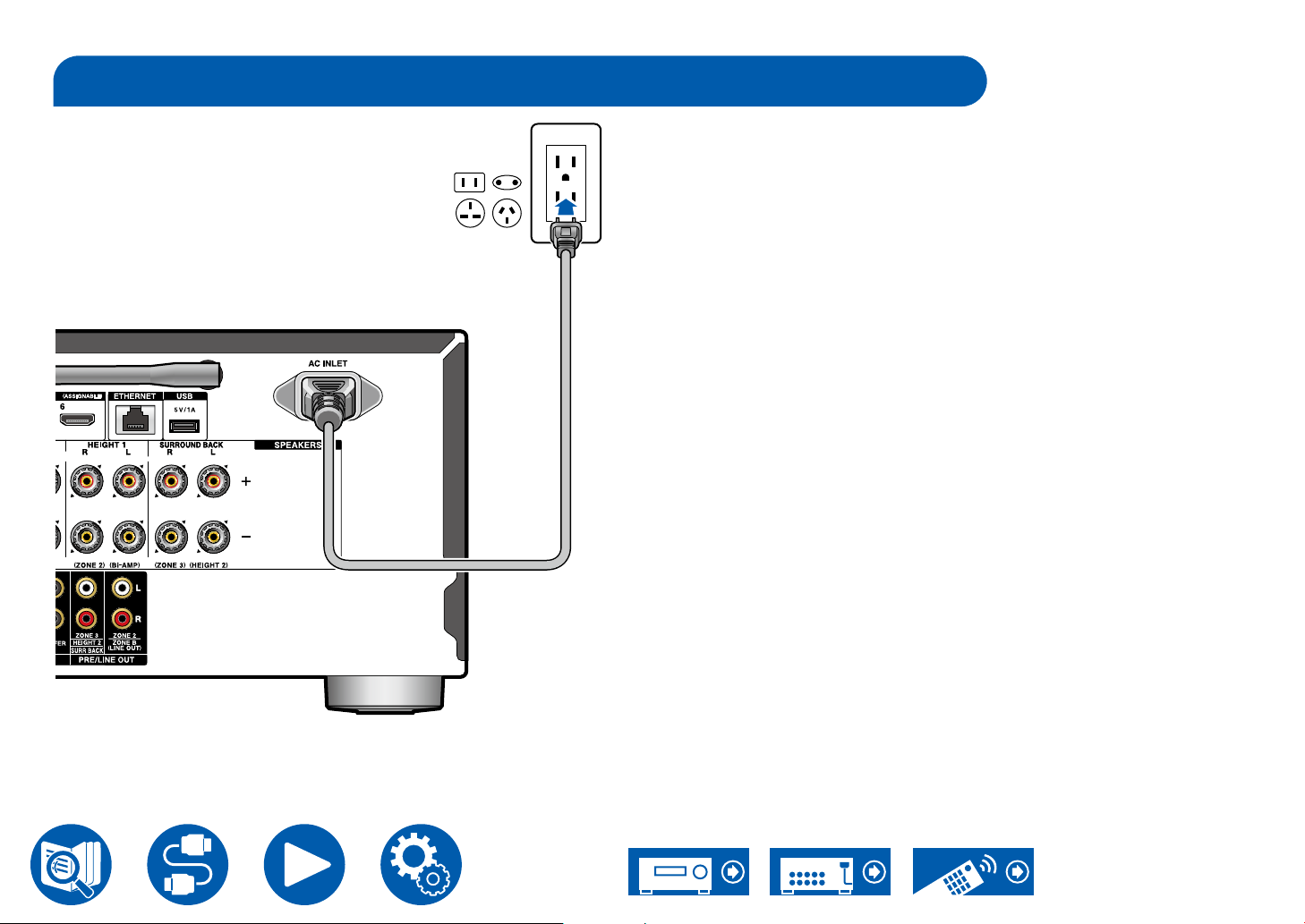
Connecting the Power Cord
Connections
Connect the power cord after all the connections are completed.
• This model includes a removable power cord. Be sure to connect the power
cord to the AC INLET of the unit rst, and then connect it to the outlet. Always
disconnect the outlet side rst when disconnecting the power cord.
a
a Power cord
61
Page 62
Playback
Basic Operations
Playing audio from an externally connected device 63
BLUETOOTH
Listening To the Radio 67
Listening Mode 71
Quick Menu 73
®
Playback 64
Network Services
Playback
Spotify 76
AirPlay
DTS Play-Fi
®
77
®
79
Amazon Alexa 80
Amazon Music 82
TIDAL 84
Connecting the Sonos System for Playback 85
Internet Radio 87
Convenience functions
Multi-zone 89
Playing different audio and video 94
Playing music les saved on a USB storage device 95
Music Server 97
Play Queue 100
Connecting a transmitter for playback 102
62
Page 63
Playing audio from an externally connected device
TV
INPUT
TV
INPUT
You can play the audio from AV components, such as Blu-ray disc players through this unit.
• When a TV is connected to the HDMI OUT SUB jack, use the HDMI Main/Sub button or "Quick Menu" ( →p73) to switch between MAIN and SUB.
Basic Operations
Perform the following procedure when this unit is on.
TV’s REMOTE
Inputs
Inputs
TV
TV
HDMI 1
HDMI 1
HDMI 2
HDMI 2
HDMI 3
HDMI 3
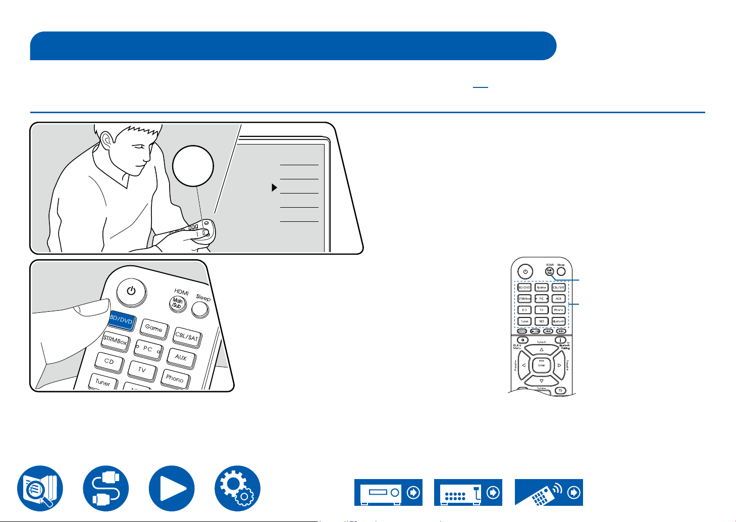
1. Switch the input on the TV to the input connected to the unit.
2. Press the input selector whose name is the same as that of the jack to which
the player is connected.
For example, press BD/DVD to play the player connected to the BD/
DVD jack. Press TV to listen to the sound of the TV. Also, to play a device
connected to the AUX Input HDMI jack or AUX Input Video/Audio jack on the
front panel, press AUX.
• When the CEC link function works, the input switches automatically
when a CEC compliant TV or player is connected to this unit using HDMI
connection.
3. Start play on the AV component.
HDMI Main/Sub
Input selector
Playback
63
Page 64
Playback
Integra DRX- XXX
BLUETOOTH® Playback
You can wirelessly play music on a smartphone or other BLUETOOTH wireless technology enabled device through the speakers connected to this unit. It is also
possible to transmit the audio from this unit to BLUETOOTH enabled headphones, wireless speakers, etc.
Playing audio from BLUETOOTH wireless technology enabled devices with this unit
Perform the following procedure when this unit is on.
Pairing
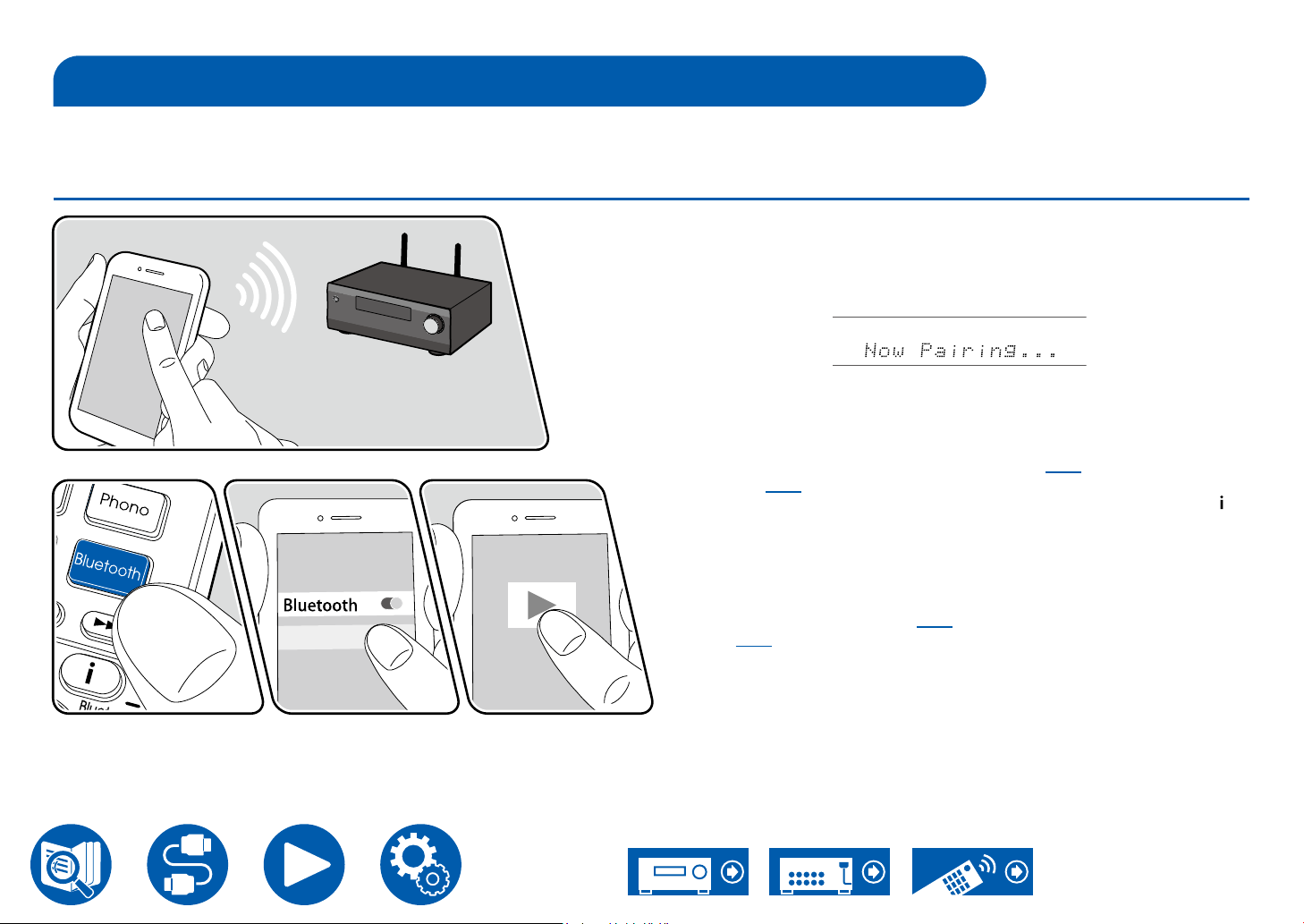
1. When you press the Bluetooth button, "Now Pairing..." appears on the display,
and the pairing mode is enabled.
2. Enable (turn on) the BLUETOOTH function of the BLUETOOTH enabled
device, and then select this unit from among the devices displayed. If a
password is requested, enter "0000".
The illustration shows an image.
• This unit is displayed as "Integra DRX-3.4 XX XXX X". This display can be
changed using the Friendly Name function ( →p127) or Integra Control
Pro ( →p148) (available on iOS or Android™).
• To connect another BLUETOOTH enabled device, press and hold the
button at least 5 seconds, and then perform step 2. This unit can store the
pairing information of up to 8 paired devices.
• The coverage area is approx. 48´/15 m. Note that connection is not always
guaranteed with all BLUETOOTH enabled devices.
• If pairing fails, then in the Setup menu, set "6. Hardware" - "Bluetooth"
- "Bluetooth Transmitter" ( →p129) to "Off" and "Bluetooth Receiver"
( →p129) to "On".
Playing Back
1. Perform the connection procedure on the BLUETOOTH enabled device.
2. Playing the music le.
The input on this unit automatically switches to "BLUETOOTH".
Turn up the volume of the BLUETOOTH enabled device to an appropriate
level.
• Due to the characteristics of BLUETOOTH wireless technology, the sound
produced on this unit may slightly be behind the sound played on the
BLUETOOTH enabled device.
64
Page 65
Playback
Transmitting audio from this unit to BLUETOOTH wireless technology enabled devices
Pairing
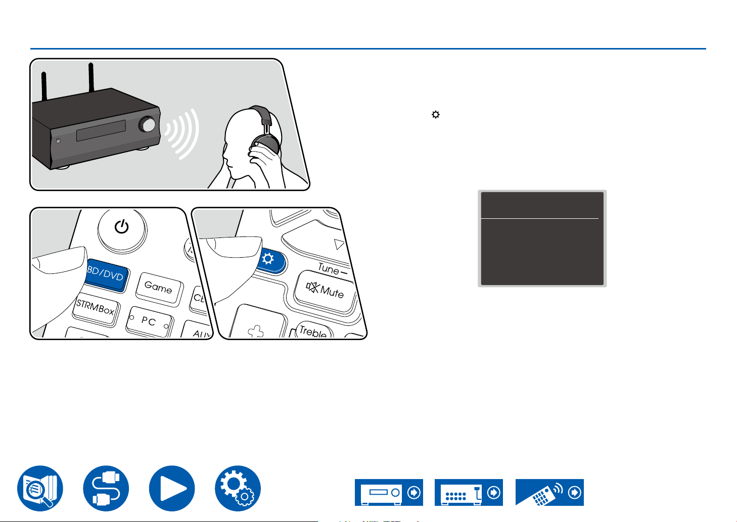
1. Press the input selector you want to play.
• Select a source other than "BLUETOOTH". This function does not work if
you select "BLUETOOTH ".
2. Press the button on the remote controller, select "6. Hardware" -
"Bluetooth" - "Bluetooth Transmitter", and press the Enter button.
3. Select either "On (Tx)" or "On (Main + Tx)" in "Bluetooth Transmitter".
• If you select "On (Tx)", playback is from the BLUETOOTH wireless
technology enabled device only, and if you select "On (Main + Tx)",
playback is from both the BLUETOOTH wireless technology enabled
device and the main unit.
The illustration shows an image.
4. In "Search Devices", press Enter.
• The search starts for BLUETOOTH wireless technology enabled devices
that are able to receive, then a list of relevant devices is displayed.
5. Select the device you want to output the audio from, and when you press
Enter the message "Now Pairing…" is displayed and the two are paired.
• Depending on the BLUETOOTH wireless technology enabled device,
you may need to pair manually. If the device name does not appear in the
list, check the settings of the BLUETOOTH wireless technology enabled
device.
Bluetooth Transmitter
Bluetooth Transmitter
Search Devices
Output Level
aptX HD
Low Latency Mode
Pairing Information
Device
Status
Set to “Off” if you are not using the Bluetooth Transmitter.
On (Tx)
Start
Variable
Clear
Ready
Off
Off
65
Page 66
Playing Back
1. Do the play operations on the AV component connected to this unit. Do the
play operations on this unit when the input is TUNER or NET.
• If "Variable" has been selected for the "Output Level", the volume can
be adjusted on this unit. Adjust to a suitable volume on the connected
BLUETOOTH wireless technology enabled device beforehand. If "Fixed" is
selected, adjust the volume on the BLUETOOTH wireless technology enabled
device.
• You cannot transmit audio to multiple BLUETOOTH wireless technology
enabled devices from this unit.
• The coverage area is approx. 48´/15 m. Note that connection is not always
guaranteed with all BLUETOOTH enabled devices.
• When "Bluetooth Transmitter" is "On (Tx)" or "On (Main + Tx)" and in the
following cases, when this unit detects a paired BLUETOOTH wireless
technology enabled device, it will automatically reconnect with that device.
– When the power is turned on again after the unit is switched to standby
– While other than "BLUETOOTH" is selected
– When the "NET" input is selected and there is audio output from a network
service/content (some services excluded)
When not using this function, select "Off" in "Bluetooth Transmitter" to cancel
the connection. Also disconnect on the receiving device (if disconnection is
possible on the receiving device).
• Audio cannot be output from a BLUETOOTH wireless technology enabled
device in the following cases:
– When the audio le is DSD format
– When playing audio from one of the following network services:
Chromecast built-in, Amazon Alexa, AirPlay, DTS Play-Fi
• Sound quality adjustments and listening modes of this unit cannot be applied
to the output audio.
• This function can be used in the main room (where this unit is located). This
function turns off if you turn on the Multi-zone function which outputs audio
from a separate room (ZONE 2/ZONE 3).
Playback
66
Page 67
Listening To the Radio
You can receive AM/FM radio stations on this unit with the built-in tuner.
Listening To the AM/FM Radio
Playback
Tuning into a Radio Station
Perform the following procedure when this unit is on.
Tuning Automatically
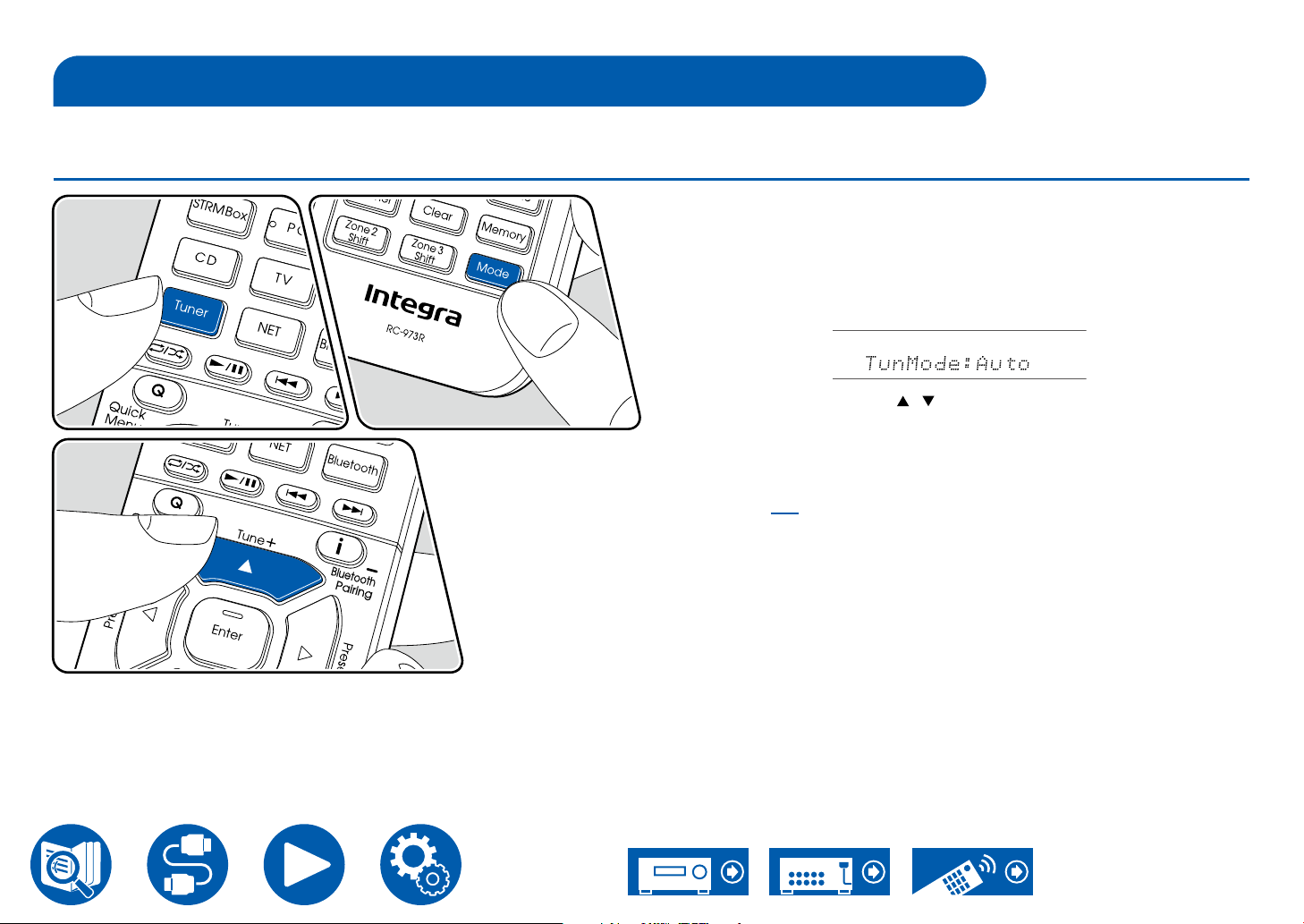
1. Press Tuner repeatedly to select either "AM" or "FM".
2. Press Mode repeatedly to display "TunMode: Auto" on the display.
3. When you press the cursors / , automatic tuning starts, and searching
stops when a station is found. When tuned in to a radio station, the "TUNED"
indicator on the display lights up. When tuned in to an FM radio station, the
"FM ST" indicator lights up.
When FM broadcasts reception is poor: Perform the procedure for "Tuning
Manually" ( →p68). Note that if you tune manually, the reception for FM
broadcasts will be monaural rather than stereo, irrespective of the sensitivity of
the reception.
67
Page 68
Playback
Tuning Manually
Note that if you tune manually, the reception for FM broadcasts will be monaural
rather than stereo, irrespective of the sensitivity of the reception.
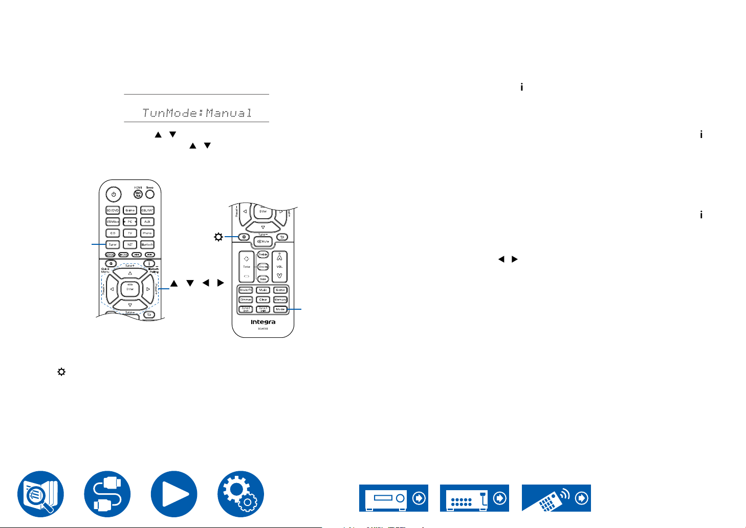
1. Press Tuner repeatedly to select either "AM" or "FM".
2. Press Mode repeatedly to display "TunMode: Manual" on the display.
3. While pressing the cursors / , select the desired radio station.
• Each time you press the cursors / , the frequency changes by 1 step.
If the button is held down, the frequency changes continuously, and if the
button is released, the frequency stops changing.
Tuner
/ / /
Enter
Mode
Frequency step setting
Press , and using the cursors and Enter, select "8. Miscellaneous" - "Tuner"
- "AM/FM Frequency Step" or "AM Frequency Step", and then select the
frequency step for your area. Note that when this setting is changed, all radio
presets are deleted.
Using RDS (Australian models)
RDS stands for Radio Data System, and is a method of transmitting data in FM
radio signals. In regions where RDS can be used, when you tune in to a radio
station broadcasting program information, the radio station name is displayed on
the display. When you press the button on the remote controller in this state,
you can use the following functions.
Display Text Information (Radio Text)
1. While the name of the station is being displayed on the display, press the
button on the remote controller once.
The Radio Text (RT), which is text information delivered by the station, is
displayed scrolling across the display. "No Text Data" is displayed when no
text information is delivered.
Search for Stations by Program Type
1. While the name of the station is being displayed on the display, press the
button on the remote controller twice.
• If none of the Program Types are set for the radio station under reception,
"None" is displayed.
2. Press the cursor buttons / on the remote controller to select the Program
Type you want to search for, and then press the Enter button to start the
search.
• The Program Types displayed are as follows: None / News (News reports)
/ Affairs (Current affairs) / Info (Information) / Sport / Educate (Education) /
Drama / Culture / Science (Science and technology) / Varied / Pop M (Pop
music) / Rock M (Rock music) / Easy M (Middle of the road music) / Light
M (Light classics) / Classics (Serious classics) / Other M (Other music)
/ Weather / Finance / Children (Children's programmes) / Social (Social
affairs) / Religion / Phone In / Travel / Leisure / Jazz (Jazz music) / Country
(Country music) / Nation M (National music) / Oldies (Oldies music) / Folk
M (Folk music) / Document (Documentary)
• The information displayed may not match the content delivered by the
station.
3. When a station is found, the station blinks on the display. Pressing the Enter
button in this state will receive that station. If you don't press the Enter button,
the unit starts to search for another station.
• If no stations are found, the message "Not Found" is displayed.
68
Page 69
• Unusual characters may be displayed when the unit receives unsupported
characters. This is not a malfunction. Also, if the signal from a station is weak,
information may not be displayed.
Playback
Presetting a Radio Station ( →p70)
69
Page 70
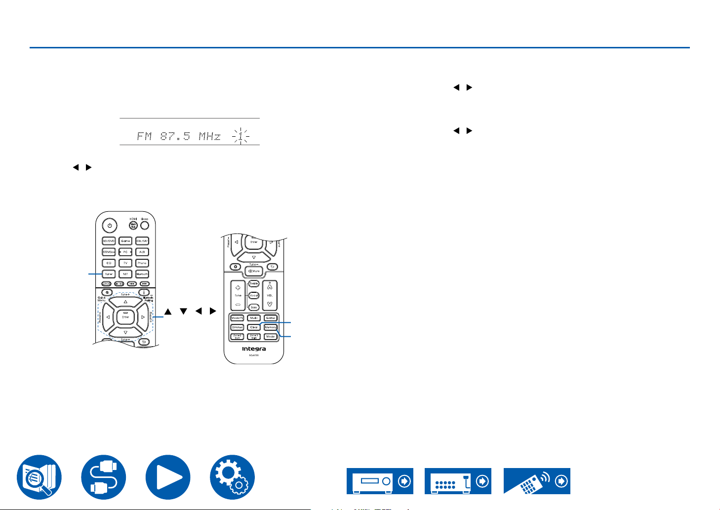
Presetting a Radio Station
Playback
Registration Procedure
You can preset up to 40 of your favorite radio stations.
After tuning in to the radio station you want to register, perform the following
procedure.
1. Press Memory so that the preset number on the display blinks.
2. While the preset number is blinking (approx. 8 seconds), repeatedly press the
cursors / to select a number between 1 and 40.
3. Press Memory again to register the station.
When the station is registered, the preset number stops ashing. Repeat this
procedure for all of your favorite radio stations.
Tuner
/ / /
Enter
Clear
Memory
Selecting a Preset Radio Station
1. Press Tuner.
2. Press the cursors / to select a preset number.
Deleting a Preset Radio Station
1. Press Tuner.
2. Press the cursors / to select the preset number to delete.
3. After pressing Memory, press Clear while the preset number is blinking,
and delete the preset number. When deleted, the number on the display
disappears.
70
Page 71
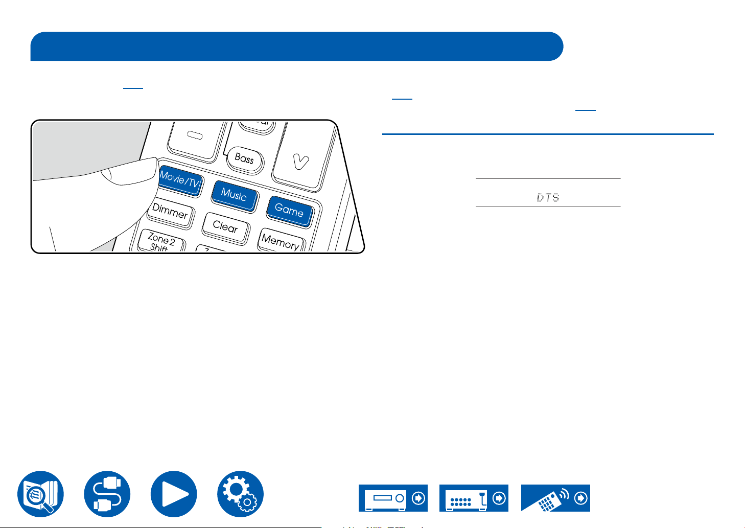
Playback
Listening Mode
This unit is equipped with a variety of listening modes, and you can select the optimum listening mode for movies, TV, music, and games by pressing Movie/TV,
Music, and Game. ( →p170)
• For details of the effects of each listening mode, refer to "Listening Mode Effects" ( →p176).
• For listening modes selectable for each audio format of input signals, refer to "Input Formats and Selectable Listening Modes" ( →p172).
Selecting a Listening mode
1. Press one from among Movie/TV, Music, and Game during playback.
2. Press the selected button repeatedly to switch the modes displayed on the
display of the main unit.
• Each of Movie/TV, Music and Game buttons stores the listening mode that
was selected last. If content incompatible of the listening mode selected last
is played, the most standard listening mode for the content is automatically
selected.
71
Page 72
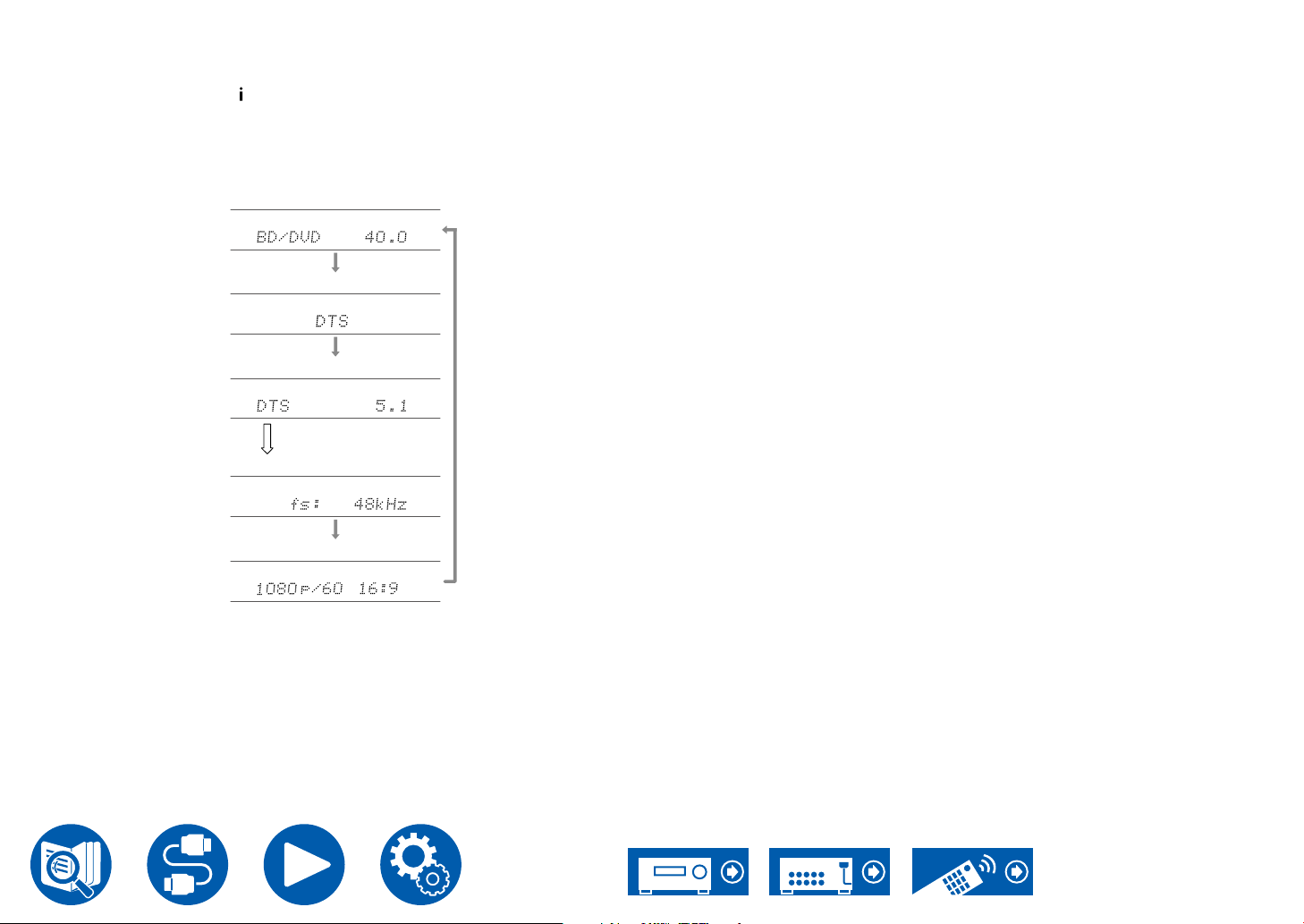
Checking the input format and listening mode
Repeatedly pressing the button on the remote controller switches the display
of the main unit in the following order.
• The content displayed depends on the source, BLUETOOTH, etc., being
played.
• Not all the information is necessarily displayed.
Input source and volume
Listening mode
Input format
The display is switched in
a few seconds.
Sampling frequency
Input signal resolution
Playback
72
Page 73
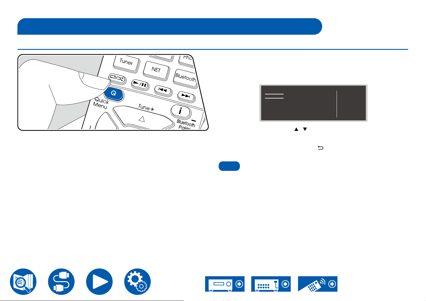
Note
Quick Menu
Menu operations
Playback
You can quickly adjust the settings you frequently use, such as tone
adjustments, etc.
You can make the settings on the TV screen during playback. Press Q on the
remote controller to display the Quick Menu.
Quick Menu
HDMI
Audio
Room EQ
Level
HDMI Out
A/V Sync
Audio Return Channel
BD/DVD
Select the item with the cursors / of the remote controller, and press the
Enter button to conrm your selection.
Use the cursors to change the settings.
• To return to the previous screen, press .
• To exit the settings, press Q.
• When the input signals are ones that need a high bandwidth, such as 8K
signals, the Quick Menu may not be displayed.
73
Page 74
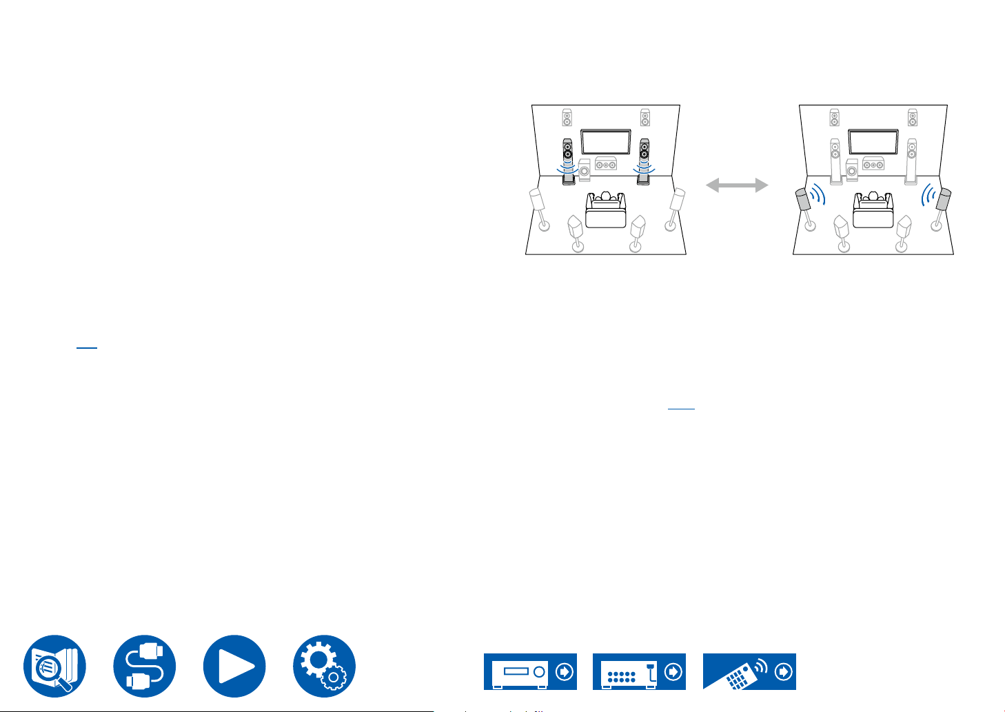
HDMI
"Front" "Surround"
HDMI Out: Select the HDMI OUT jack to output video signals from "MAIN",
"SUB", and "MAIN+SUB".
A/V Sync: If the video is behind the audio, you can delay the audio to offset the
gap. The setting can be set for each input.
• It cannot be set if the listening mode is Direct.
Audio Return Channel: You can enjoy the sound of the HDMI-connected ARC-
compatible T V through the speakers connected to the unit. Select "On" when
listening to the audio of TV using the speakers of this unit. Select "Off" when the
ARC function is not used.
Audio
Music Optimizer: Improve the quality of the compressed audio. Playback sound
of lossy compressed les such as MP3 will be improved. The setting can be set
for each input. This works in signals whose sampling frequencies are 48 kHz or
less. The setting is not effective in the bitstream signals.
• It cannot be set if the listening mode is Direct.
• This cannot be selected when either of the slots is selected with "Dirac Live"
( →p75).
Late Night: Enable small sounds to be easily heard in detail. It is useful when
you need to reduce the volume while watching a movie late night.
• This function cannot be used in the following cases.
– When playing Dolby Digital Plus or Dolby TrueHD with "Loudness
Management" set to "Off"
– When the input signal is DTS:X, and "Dialog Control" is not 0 dB
– When the input signal is Analog/DSD and the listening mode is Direct
Playback
Stereo Assign: This function enables you to select a pair of speakers to output
stereo sound. Apart from the front speakers (Front), you can select the Surround
speakers (Surround), Surround Back speakers (Surround Back), Height 1
speakers (Height 1) and Height 2 speakers (Height 2).
Selectable
• The listening mode switches to "Stereo" if the audio output destination is
changed.
Zone B: Select a method of outputting audio to ZONE B from among "Off",
"On (A+B)" and "On (B)".
• In the following cases, "Zone B" cannot be selected.
– When ZONE 2 is On
– When "2. Speaker" - "Conguration" - "Zone 2 Preout" on the Setup menu
is set to "Zone 2". ( →p113)
Digital Filter: You can switch the type of digital lter in the AUDIO DAC (digital
analog converter). You can choose "Slow" (gives the sound a soft and uid feel),
"Sharp" (gives the sound more structure and rmer feel) or "Auto" (auto). The
setting can be separately set to each input selector. This can be set when the
sampling frequency is 44.1 kHz or more.
74
Page 75
Playback
Room EQ
Dirac Live (*1): You can select the equalizers measured with Dirac Live
( →p145, p149) from "Slot1" to "Slot3". When disabling the equalizer, select
"O f f ".
• The Dirac Live measurement results are saved in "Slot1" to "Slot3", but you
are able to register your own original sound quality with "Manual Adjust"
( →p150).
• This cannot be selected when measurements are made using "AccuEQ
Room Calibration".
AccuEQ (*1)(*2): Enable or disable the equalizer function that corrects for
sound distortion caused by the acoustic environment of the room.
On (All Ch): EQ that corrects according to the room acoustics acquired with the
AccuEQ calibration is applied to all channels.
On (ex. L/R): The same EQ as "On (All Ch)" is applied to speakers other than the
Front Speakers. EQ correction for the Front Speakers is turned off.
• The setting can be separately set to each input selector.
Manual Equalizer (*1)(*2): Select "Preset 1" to "Preset 3" congured in "2.
Speaker" - "Equalizer Settings" on the Setup menu. When this is set to "Off", the
same sound eld setting is applied to all ranges.
Cinema Filter (*1)(*2): Adjusts the soundtrack with the enhanced high range so
that it suits a home theater.
This function can be used in the following listening modes: Dolby Audio - DD,
Dolby Audio - DD+, Dolby Audio - Surr, Dolby Audio - TrueHD, Multichannel,
DTS, DTS-ES, DTS 96/24, DTS-HD High Resolution Audio, DTS-HD Master
Audio, DTS Neural:X, DTS Express and DSD
EQ for Standing Wave (*1)(*2): Setting this "On" will control the effect of
the standing wave generated by the sound wave reected by wall or similar
interfering with the original sound wave.
(*1) It cannot be set if the listening mode is Direct.
(*2) This function cannot be used if Dirac Live ( →p75) is being used.
Furthermore, there is no effect even if it can be selected.
Level
Front: Adjust the speaker level of the front speakers while listening to the sound.
Center: Adjust the speaker level of the center speaker while listening to the
sound.
Subwoofer: Adjust the speaker level of the subwoofer while listening to the
sound.
• If you set the unit to the standby mode, the adjustments you made will be
restored to the previous statuses.
75
Page 76
Spotify
Use your phone, tablet or computer as a remote control for Spotify.
Go to spotify.com/connect to learn how.
Playback
76
Page 77
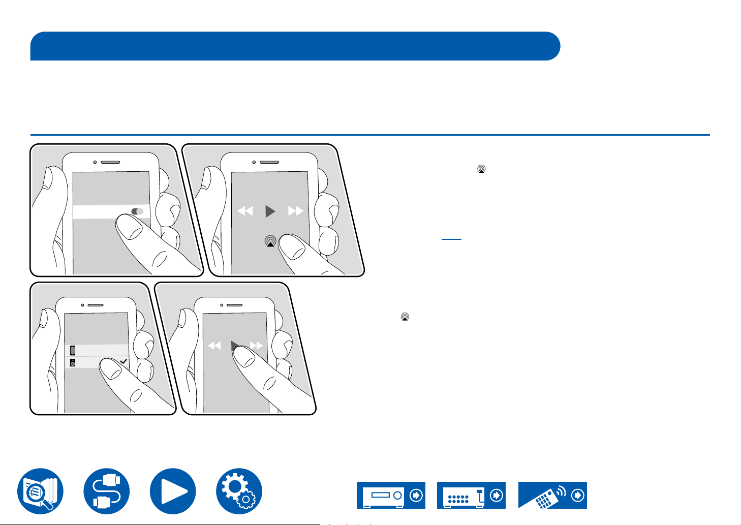
Playback
Integra DRX- XXXXXX
iPhone
Wi-Fi
AirPlay
By connecting this unit to the same network as that of iOS devices such as iPhone®, iPod touch® and iPad®, you can enjoy music les on iOS devices wirelessly.
• Update the OS version on your iOS device to the latest version.
• Depending on the iOS version, operation screens or operation procedures on the iOS device may be different. For details, refer to the operating instructions for the
iOS device.
®
Basic Operations
1. Connect the iOS device to the access point where this unit is connected via
network.
2. Tap the AirPlay icon in the play screen of the music app on an iOS device
that supports AirPlay and select this unit from the list of devices displayed.
3. Play the music le on the iOS device.
• When "6. Hardware" - "Power Management" - "Network Standby" is set to
"Off" in the Setup menu, turn this unit on manually, and press the NET button
on the remote controller. In the factory default setting, the Network Standby
function ( →p131) is set to On.
• Due to the characteristics of AirPlay wireless technology, the sound produced
on this unit may slightly be behind the sound played on the AirPlay-enabled
device.
You can also play the music les on a PC with iTunes (Ver. 10.2 or later)
equipped. Conrm that this unit and the PC are connected to the same network
beforehand. Then, press NET on the remote controller. Next, click the AirPlay
in iTunes, select this unit from the displayed devices, and start play of a
icon
music le.
e.g., iOS 10
77
Page 78
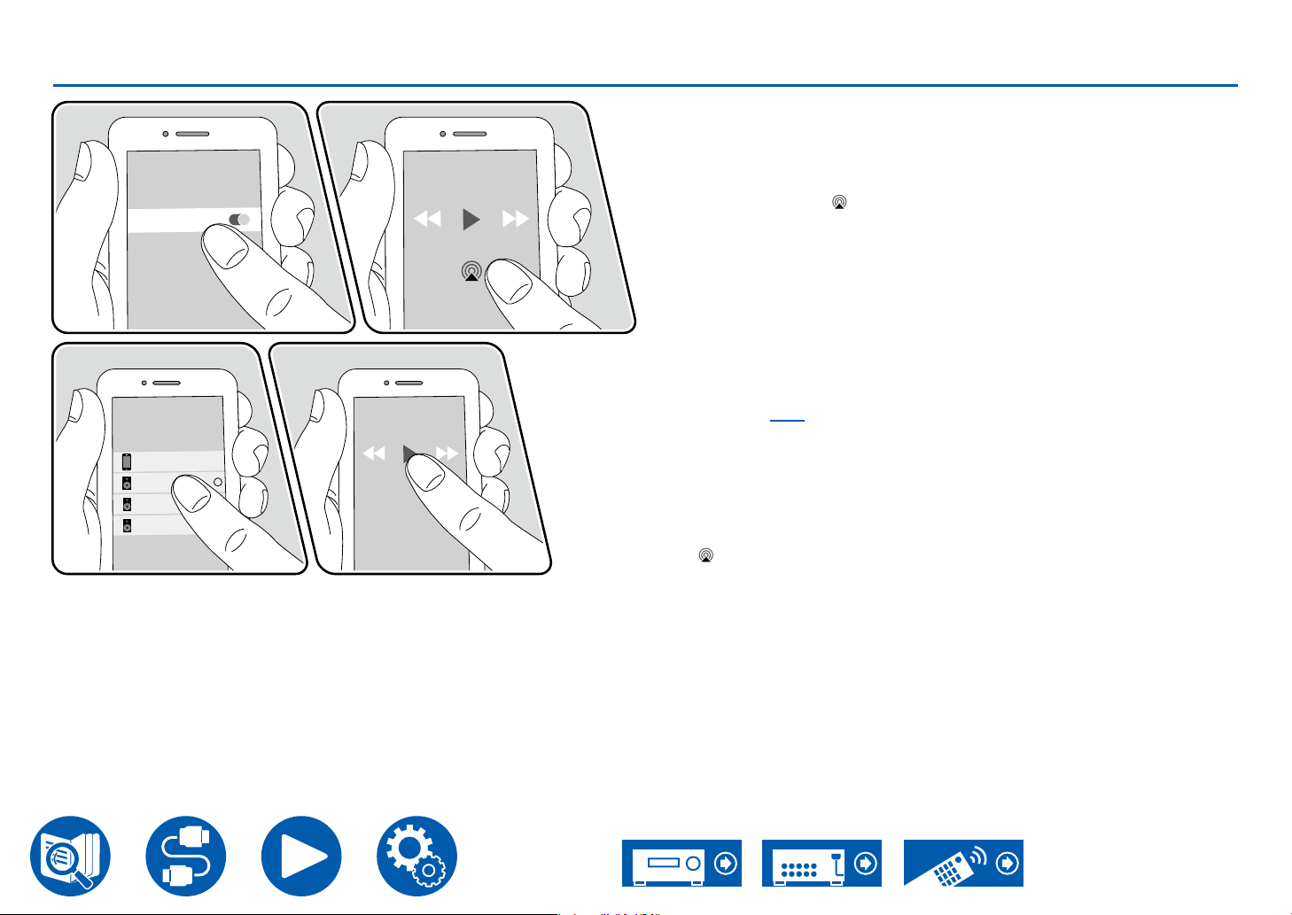
Playing Back on multiple devices (AirPlay2)
Integra DRX- XXXXXX
iPhone
Integra XXXXXXXX
Integra XXXXXXXX
Wi-Fi
e.g., iOS 11.4
Playback
This unit supports AirPlay2. If the version of the iOS device is iOS11.4 or later,
you can play the tracks on the iOS device simultaneously on this device and on
another device that supports AirPlay2.
1. Connect the iOS device to the access point where this unit is connected via
network.
2. Tap the AirPlay icon on the play screen of the music play application on
the iOS device, and select this unit and AirPlay2-supported devices to play
from the displayed devices.
• AirPlay2-supported devices are displayed with white circle on the right
side.
• Multiple AirPlay2-supported devices can be selected.
• The volume can be adjusted on individual devices.
3. Play the music le on the iOS device.
• When "6. Hardware" - "Power Management" - "Network Standby" is set to
"Off" in the Setup menu, turn this unit on manually, and press the NET button
on the remote controller. In the factory default setting, the Network Standby
function ( →p131) is set to On.
• Due to the characteristics of AirPlay wireless technology, the sound produced
on this unit may slightly be behind the sound played on the AirPlay-enabled
device.
You can also play the music les on a PC with iTunes (Ver. 12.8 or later)
equipped. Conrm that this unit and the PC are connected to the same network
beforehand. Then, press NET on the remote controller. Next, click the AirPlay
in iTunes, select this unit and AirPlay2-supported devices to play from
icon
the displayed devices, and start play of a music le.
78
Page 79
Playback
DTS Play-Fi
When connecting this unit to the same network as mobile devices, such as
a smartphone and tablet, you can enjoy music played on the mobile device
wirelessly. Music from a streaming distribution service or music in the music
library on a mobile device can be played. This function also supports a playlist
on iTunes. Also, connecting multiple speakers supporting DTS Play-Fi on
the same network will enable "Group playback" that plays the same music in
separate rooms at home. To enjoy this function, download Integra Music Control
App (available on iOS or Android™).
®
https://play-.com/
Playing Back
1. Download Integra Music Control App using your mobile device.
https://integrahometheater.jp/play/app_i.html
2. Connect the mobile device to the network where this unit is connected.
3. Starting up Integra Music Control App will automatically display compatible
devices.
4. Select this device from the compatible devices. Then, a list of applications
such as a music streaming distribution service is displayed. Select
the content to play, and perform operation according to the on-screen
instructions.
• When "6. Hardware" - "Power Management" - "Network Standby" is set to
"Off" in the Setup menu, turn this unit on manually, and press the NET button
on the remote controller. In the factory default setting, the Network Standby
function ( →p131) is set to On.
• For detailed operation and FAQ, visit the following URL.
https://integrahometheater.jp/play/info_i.html
• To use a music streaming distribution service, user registration may be
required.
• This unit does not support the following DTS Play-Fi functions.
– Spotify
– Wireless Surround Sound
– Line In Rebroadcast
– Internet Radio
• Some of the settings in the "Setup menu" cannot be changed on this unit. To
change those settings, cancel the connection of this unit from the application.
79
Page 80
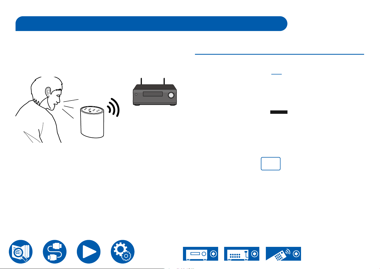
Amazon Alexa
Playback
Alexa is a cloud-based voice service developed by Amazon. When this unit is
registered with an Amazon account, you can use a terminal with Amazon Alexa
(an Amazon Echo, etc.) or Amazon Alexa App (available on iOS and Android™)
to perform operations such as adjusting the volume of this unit or playing music
using voice commands.
• You need an Amazon account to use Amazon Alexa. For more information,
see the Amazon website.
Registering this unit with an Amazon account
1. Register with the Amazon account on Integra Control Pro. This cannot be set
with operations on this unit.
Refer to "Integra Control Pro" ( →p148) for information about the app.
2. Start Integra Control Pro and tap the unit when displayed.
3. Tap "NET" or "NETWORK" at the top of the Integra Control Pro screen, and
after switching to the network menu, tap the "amazon alexa" icon.
• If the login screen is not displayed but an update or installation screen is
displayed instead, perform the update or installation according to the onscreen instructions.
Available ser vices may differ depending on your area.
4. Tap "Start Setup", and in the Setup screen, select the language and register
the device name. Select the same language as the one you have selected
for your other terminals with Amazon Alexa (an Amazon Echo, etc.). For the
device name, use one that can easily be called up vocally.
For example: Speaker
5. Tap "Next" to display the Amazon Alexa screen.
6. Follow the on screen instructions to enter the Amazon account information,
such as your email address and password, to log into Amazon (*1). After
logging in, tap "Allow" and register this unit with an Amazon account.
80
Page 81
(*1) Log in using the same account as other terminals with Amazon Alexa.
7. When registration is nished, the screen returns to the one for Integra
Control Pro. Follow the on screen instructions and talk to the terminal with
Amazon Alexa (an Amazon Echo, etc.), and conrm that you can use voice
commands.
For example: "Alexa, raise the volume of the speaker (*2)"
"Alexa, play music from the speaker (*2)"
(*2) Use the device name you registered in Step 4 when talking.
Playback
Operating this unit
You can use voice commands to adjust the volume on this unit, start and stop
music, and skip music up or down.
1. With the unit on, speak at the terminal with Amazon Alexa (an Amazon Echo,
etc.). When using the Amazon Alexa app, after starting the app, tap the Alexa
logo and speak at the mobile device.
For example: "Alexa, raise the volume of the speaker (*3)"
"Alexa, play music from the speaker (*3)"
(*3) Use the device name you registered in Step 4 of "Registering this unit
with an Amazon account" when talking.
• Refer to the website for details about voice commands. (Click here )
• It is not possible to turn the unit on or off, or to switch the listening mode.
• Refer to the Amazon websites for information about operation of the Amazon
Alexa app.
81
Page 82
Amazon Music
Registering this unit with Amazon Music allows you to enjoy the music
distribution service provided by Amazon.
• To play Amazon Music, you need to have your Amazon account and sign up
for Amazon Prime or Amazon Music Unlimited. For more information, see the
Amazon website.
Amazon Music is now available in several countries. If Amazon Music is not
available in your country, please visit https://music.amazon.com/ for more info.
Playback
Registering This Unit with Amazon Music
1. Register with the Amazon account on Integra Control Pro. This cannot be set
with operations on this unit.
Refer to "Integra Control Pro" ( →p148) for information about the app.
2. Start Integra Control Pro and tap the unit when displayed.
3. Tap "NET" or "NETWORK" on the upper part of the Integra Control Pro’s
screen to switch to the network menu. Then tap the "Amazon Music" icon to
display the login screen of Amazon Music. (Depending on the model, the icon
names may be different.)
• If the login screen is not displayed but an update or installation screen is
displayed instead, perform the update or installation according to the onscreen instructions.
Available ser vices may differ depending on your area.
4. Enter the Amazon account information such as email address and password
to log in to Amazon. When the login is successful and this unit is registered,
the Amazon Music menu is displayed.
For playback, proceed to step 3 in the next section.
82
Page 83
Playing Amazon Music using the Integra Control Pro
1. Start up Integra Control Pro. This unit is automatically displayed after startup.
Then, tap and select this unit displayed.
2. Tap "NET" or "NETWORK" on the upper part of the screen to switch to the
network screen. Then tap the "Amazon Music" icon.
3. Select the content to play from the menu screen of Amazon Music to start
playback.
Playing Amazon Music using the remote controller
1. Switch the input on the TV to the input connected to the unit.
2. Pressing NET will display the Network Functions list screen on the T V.
3. Select "Amazon Music" with the cursors and press Enter to conrm.
4. Select the content to play from the menu screen of Amazon Music to start
playback.
Playback
83
Page 84
TIDAL
Registering this unit with TIDAL allows you to enjoy the music distribution
service provided by TIDAL. You can register this unit on the screen of Integra
Control Pro by downloading Integra Control Pro (available on iOS or Android™)
to mobile devices such as a smartphone and tablet.
• You need a TIDAL account to play back TIDAL. For more information, see the
TIDAL website.
Registering this unit with TIDAL
• You can register this unit with TIDAL using Integra Control Pro. The
registration cannot be performed by operation of this unit.
1. Connect this unit to your home network by the network settings on this unit.
2. Download Integra Control Pro using your mobile device.
3. Connect the mobile device to the network where this unit is connected.
4. Start up Integra Control Pro to automatically display this unit. Tap and select
this unit displayed.
5. Tap "NET" or "NETWORK" on the upper part of the Integra Control Pro’s
screen to switch to the network menu. Then tap the "TIDAL" icon to display
the login screen of TIDAL. (Depending on the model, the icon names may be
different.)
Playback
• If the login screen is not displayed but an update or installation screen
is displayed instead, perform the update or installation according to the
onscreen instructions.
Available ser vices may differ depending on your area.
6. Enter the TIDAL account information such as login ID and password to log in
to TIDAL. When the login is successful and this unit is registered, the TIDAL
menu is displayed.
For playback, proceed to step 3 in the next section.
Playing TIDAL
1. Start up Integra Control Pro. This unit is automatically displayed after startup.
Then, tap and select this unit displayed.
2. Tap "NET" or "NETWORK" on the upper part of the screen to switch to the
network screen. Then tap the "TIDAL" icon.
3. Select the content to play from the menu screen of TIDAL to start playback.
• To play TIDAL using the remote controller, operate the input selector on the
remote controller to display the network menu, and select "TIDAL" from the
menu.
84
Page 85
Connecting the Sonos System for Playback
How to Connect This Unit and Sonos Connect
1. Connect the Sonos Connect to the AUDIO IN jack of this unit with the RCA
Connecting this unit and Sonos Connect allows you to send the music or music
sources on the Sonos App to this unit. Through Sonos Connect, you can play
this unit with the same group of another Sonos device on the network or can
play only on this unit. Also, if you start to play music from Sonos App, this unit is
automatically turned on and the link function to switch input works.
• When "6. Hardware" - "Power Management" - "Network Standby" is set to
"Off" in the Setup menu, turn this unit on manually, and press the NET button
on the remote controller. In the factory default setting, the Network Standby
function ( →p131) is set to On.
• You can register a maximum of 3 Sonos Connect.
Setting Up
A setup is required to play Sonos on this unit. Make the setting according to the
following procedure.
1. Press the button on the remote controller, select "6. Hardware" - "Works
Necessary Equipment
2. Select the following items with the cursors / and set each item.
• Sonos Connect
• RCA audio cable (supplied with Sonos Connect)
Playback
audio cable supplied with the Sonos Connect. Any input jacks other than the
PHONO jack can be used.
• A digital cable can also be connected. For details, refer to the instruction
manual of Sonos.
• You can change the name of the input selector displayed on this unit to
easier-to-understand name. For example, the input connected to Sonos
Connect can be changed from "CD" (or another input selector name) to
"SONOS". Press the
- "Name Edit" and then change the name.
with SONOS", and press the Enter button.
Input Selector:
Enable the interlocking function with the Sonos Connect. With the cursors /
, select the input selector to which the Sonos Connect is connected.
Connected Device:
Press the Enter button to display Sonos devices connected to the same
network as the network of this unit. Select the Sonos Connect connected to
the unit and press the Enter button.
• Products (e.g. Play:3 unequipped with an output terminal) other than the
Sonos Connect are also displayed in the device list and selectable. In
that case, when playback on the Sonos side starts, the input is switched,
however, audio is not output. Select the room name of the connected
Sonos Connect.
button on the remote controller, select "4. Source"
85
Page 86
• Up to 32 devices can be displayed on the Sonos product list screen. If you
cannot nd the Sonos Connect to be interlocked, return to the previous
screen, turn off the product you do not want to interlock, and try again.
Output Zone:
With the cursors / , select the ZONE where you want to listen to the
music.
"Main": Outputs audio only to the main room (where this unit is located).
"Zone 2": Outputs audio only to the separate room (Zone 2).
"Main/Zone 2": Outputs audio to both the main room and separate room
(Zone 2).
"Zone 3": Outputs audio only to the separate room (Zone 3).
"Main/Zone 3": Outputs audio to both the main room and separate room
(Zone 3).
"Zone 2/Zone 3": Outputs audio to both the separate rooms (Zone 2 and Zone
3).
"Main/Zone 2/Zone 3": Outputs audio to the main room and both separate
rooms (Zone 2 and Zone 3).
Preset Volume:
You can set the volume that Sonos Connect will be played at beforehand.
Select a value from "Last" (Volume level before entering standby mode),
"Min", "0.5" to "99.5" and "Max".
• When making the setting for the second and third unit, press the cursor
several times to move to the next page, and change the menu from
"SONOS-1" to "SONOS-2" or "SONOS-3".
Playback
Playing Sonos on This Unit
1. Select desired tracks using Sonos App and send the tracks to the room
where this unit is located (or to the group). It is recommended to give an easyto-remember name to the combination of this unit and Sonos Connect, such
as TV Room or Living Room where this unit is located.
• If the input selector of this unit is not automatically switched even after the
start of music playback, stop the playback once and start again.
• When the "Volume Pass Through" mode has been selected with the Sonos
App settings, you can use the Sonos App to control the volume of this unit.
* You cannot use the "Preset Volume" function when the "Volume Pass
Through" mode has been selected.
86
Page 87
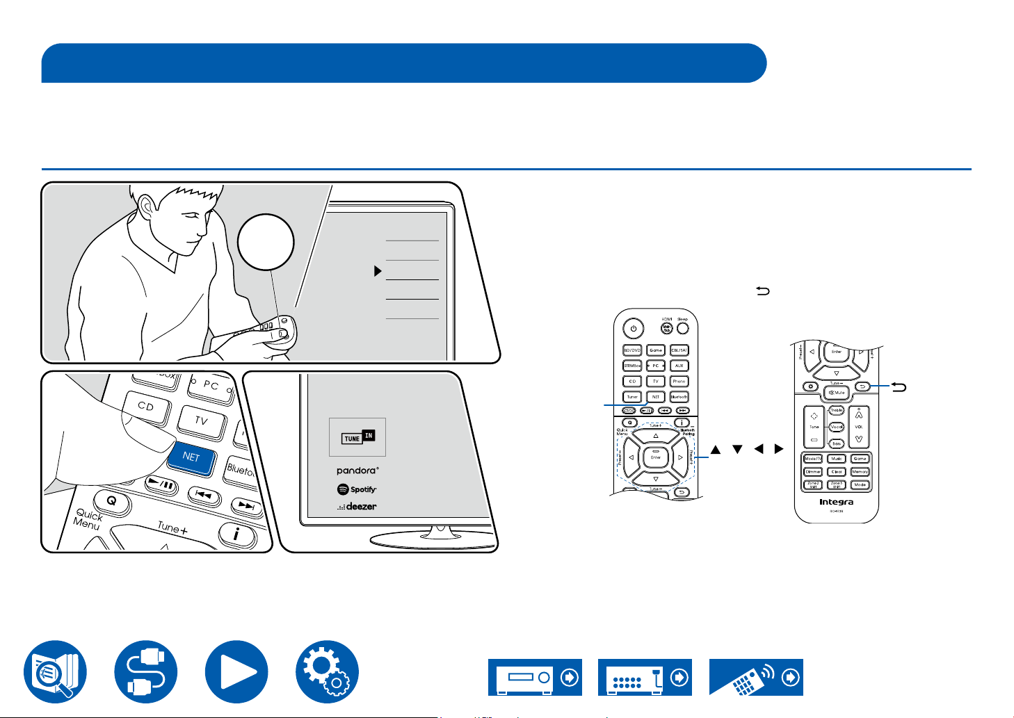
Playback
TV
INPUT
Internet Radio
By connecting this unit to an Internet-connected network, you can enjoy Internet radio services such as TuneIn Radio.
• To play Internet radio services, the network needs to be connected to the Internet.
• Depending on the Internet radio service, a user registration may be required on your PC beforehand. For details of each service, visit the website of each service.
Playing Back
Perform the following procedure when this unit is on.
TV’s REMOTE
Inputs
TV
HDMI 1
HDMI 2
HDMI 3
1. Switch the input on the TV to the input connected to the unit.
2. Pressing NET will display the Network services list screen on the TV.
3. Select your preferred Internet radio service using cursor, and press Enter to
conrm the selection.
4. Following the on-screen instructions, select a radio station and program using
cursor, and then press Enter to play.
• To return to the previous screen, press .
NET
/ / /
Enter
The illustration shows an image.
87
Page 88
Internet Radio Service Menu
You can bookmark specic stations, or delete stations that have been
bookmarked. The displayed menu varies according to the service being
selected.
The menu icon
icon is displayed, pressing Enter will display the menu on the screen. When
multiple icons are displayed, select the
is displayed while a station is being played. When only this
icon with the cursor, and press Enter.
Regarding the TuneIn Radio Account
If you create an account on the TuneIn Radio website (tunein.com), and log in it
from this unit, your favorite radio stations or programs you have followed on the
website are automatically added to your "My Presets" on this unit. "My Presets"
is displayed on the next level in the hierarchical structure of TuneIn Radio. To
display a radio station added to "My Presets", you need log into TuneIn Radio
from the unit. To log in, select "Login" - "I have a TuneIn account" in the "TuneIn
Radio" top list on the unit, and then enter your user name and password.
• If you select "Login" on this unit, a registration code is displayed. By using
this code, you can associate the device on the My Page section of the TuneIn
Radio website so that you can log in from "Login" - "Login with a registration
code" without entering the user name and password.
Playback
88
Page 89
Playback
Multi-zone
You can enjoy 2 ch audio in the separate room (Zone 2/Zone 3) while performing playback in the main room (where this unit is located). The same source can be
played back in the main room and Zone 2/Zone 3 simultaneously. Also, different sources can be played back in both rooms. For the "NET" or "BLUETOOTH" input
selector, you can select only the same source for the main room and separate room. If you select "NET" in the main room and then select "BLUETOOTH" in the
separate room, the main room setting switches to "BLUETOOTH". You cannot select different stations of AM/FM broadcasts for the main room and separate room.
Using Integra Control Pro ( →p148) is convenient for operations of multi-zone playback. You can use it on mobile devices, such as a smartphone and tablet to which
Integra Control Pro (available on iOS or Android™) has been downloaded.
Playing Back (ZONE 2) ( →p90)
89
Page 90
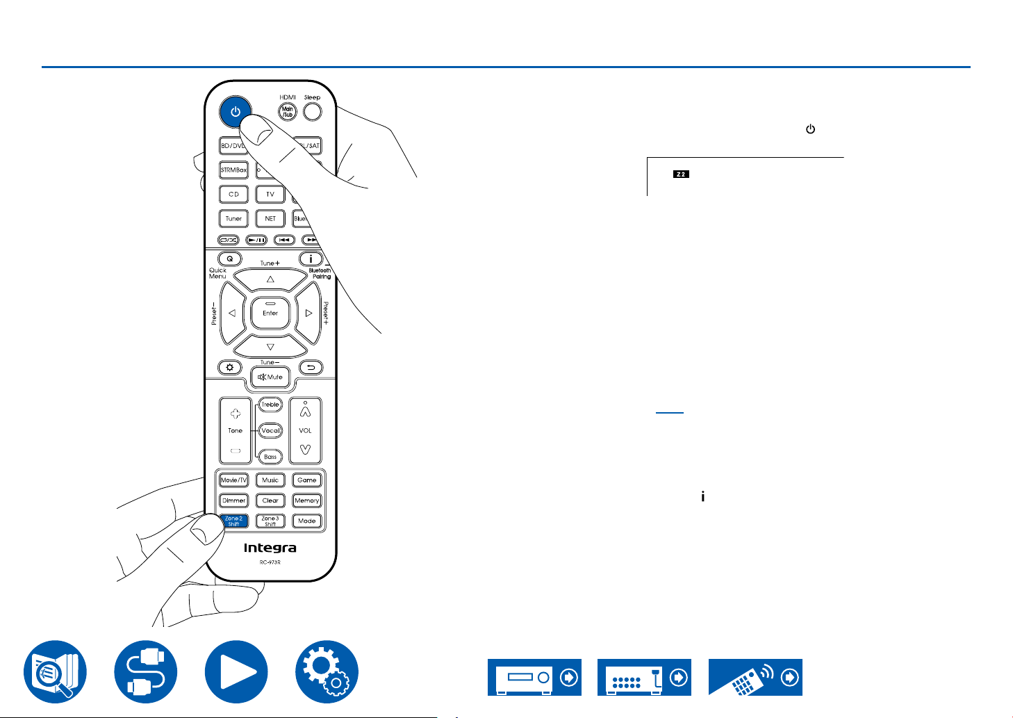
Playing Back (ZONE 2)
2
1
Playback
In remote controller operation, while pressing and holding the Zone 2 Shift
button, press other buttons for operation.
1. While pressing and holding the Zone 2 Shift button on the remote controller,
point the remote controller at this unit and press .
• "Z2" on the display of the main unit lights up.
2. While pressing and holding the Zone 2 Shift button on the remote controller,
press the input selector of the input source you want to play in the separate
room. To control on the main unit, press the Zone 2 button, and then within
8 seconds, press the input selector button of the input to be played in the
separate room. To play the same source in the main room and separate
room, press the Zone 2 button of the main unit twice.
3. When using the ZONE 2 PRE/LINE OUT connection, adjust the sound
volume on the integrated amplier in the separate room. For the ZONE
speaker output, while pressing and holding the Zone 2 Shift button on the
remote controller, adjust the volume with the volume button. To do this on
the main unit, press the Zone 2 button, and then within 8 seconds, adjust the
volume using the Master Volume dial.
• When connecting the power amplier set "7. Multi Zone" - "Zone 2" -
"Output Level" ( →p137) to "Variable". If it is not set, a large volume is
output and the power amplier, speakers, etc. may be damaged.
• The sound quality of the power amplier connected in the separate room
can also be adjusted. Press the Zone 2 button of this unit, and then press
the Tone button within 8 seconds. Press + and - button for adjustment.
• Information of a connected device can be displayed on the T V in the
separate room. Press the button while pressing and holding the Zone 2
Shift button on the remote controller.
• If you turn the unit to standby during multi-zone playback, the Z2 indicator is
dimmed, and the playback mode is switched to playback in a separate room
only. Setting ZONE 2 to on while the unit is in standby also switches the
playback mode to playback in the separate room only.
90
Page 91
• The audio from externally connected AV components can be output to ZONE
2 only when the audio is analog or 2 ch PCM signal. When the AV component
is connected to this unit with an HDMI cable, digital coaxial cable or digital
optical cable, change the audio output of the AV component to the PCM
output.
• When video and audio via HDMI input are output to ZONE 2, set "1. Input/
Output Assign" - "TV Out / OSD" - "Zone 2 HDMI" ( →p108) to "Use" on the
Setup menu.
• DSD audio signals cannot be output to ZONE 2 with the "NET" input selector.
• If ZONE 2 is on, power consumption during standby will increase.
• This function turns off if you use "Transmitting audio from this unit to
BLUETOOTH wireless technology enabled devices" ( →p65).
To disable the function: While pressing and holding the Zone 2 Shift button on
the remote controller, press
.
Playback
Playing Back (ZONE 3) ( →p92)
91
Page 92
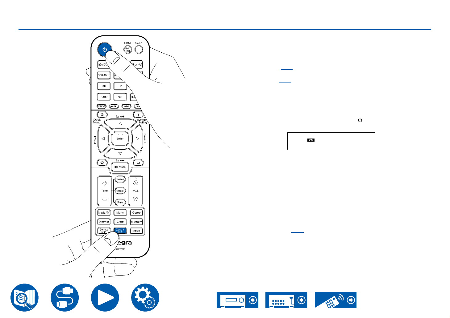
Playing Back (ZONE 3)
2
1
Playback
In remote controller operation, while pressing and holding the Zone 3 Shift
button, press other buttons for operation. Settings are required to playback a
source in ZONE 3.
When outputting from the speakers: Set "2. Speaker" - "Conguration" -
"Zone Speaker" ( →p113) in the Setup menu to "Zone 2/Zone 3".
When outputting from the integrated amplier: Set "2. Speaker" -
"Conguration" ( →p112) in the Setup, to one of the following.
– Set "Speaker Channels" to "2.1 ch", "3.1 ch", "4.1 ch", or "5.1 ch"
– Set "Speaker Channels" to "2.1.2 ch", "3.1.2 ch", "4.1.2 ch", or "5.1.2 ch", and
set "Bi-Amp" and "Zone Speaker" to "No"
1. While pressing and holding the Zone 3 Shift button on the remote controller,
point the remote controller at this unit and press
• "Z3" on the display of the main unit lights up.
2. While pressing and holding the Zone 3 Shift button on the remote controller,
press the input selector of the input source you want to play in the separate
room. To control on the main unit, press the Zone 3 button, and then within
8 seconds, press the input selector button of the input to be played in the
separate room. To play the same source in the main room and separate
room, press the Zone 3 button of the main unit twice.
3. While pressing and holding the Zone 3 Shift button on the remote controller,
adjust the volume with the volume button. To do this on the main unit, press
the Zone 3 button, and then within 8 seconds, adjust the volume using the
Master Volume dial.
• When connecting the power amplier set "7. Multi Zone" - "Zone 3" -
"Output Level" ( →p137) to "Variable". If it is not set, a large volume is
output and the power amplier, speakers, etc. may be damaged.
• If you turn the unit to standby during multi-zone playback, the Z3 indicator is
dimmed, and the playback mode is switched to playback in a separate room
only. Setting ZONE 3 to on while the unit is in standby also switches the
playback mode to playback in the separate room only.
.
92
Page 93
• For ZONE 3 output, audio from externally connected AV components can be
output only when it is an analog audio signal.
• DSD audio signals cannot be output to ZONE 3 with the "NET" input selector.
• If ZONE 3 is on, power consumption during standby will increase.
• This function turns off if you use "Transmitting audio from this unit to
BLUETOOTH wireless technology enabled devices" ( →p65).
To disable the function: While pressing and holding the Zone 3 Shift button on
the remote controller, press
.
Playback
93
Page 94
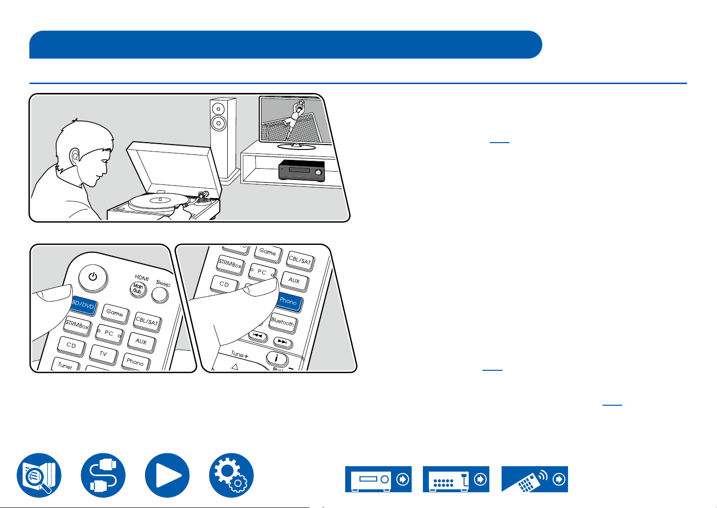
Playing different audio and video
Displaying Your Favorite Video on TV While Playing Music
While listening to the music from a CD or BLUETOOTH enabled device, you can
display video on TV from an AV component such as a Blu-ray Disc player.
• For audio playback, you can select an input selector to which video input is
not assigned, such as "CD", "PHONO", "TUNER", "NET" and "BLUETOOTH".
• When "OSD Language" ( →p108) is set to Chinese, the audio from "NET"
and "BLUETOOTH" cannot be played.
Perform the following procedure when this unit is on.
1. Switch the input on the TV to the input connected to the unit.
2. Press an input selector such as BD/DVD button connected to the AV
component of which the video is to be displayed on TV.
• This operation is not necessary if the same input selector has been
selected in the previous operation.
The illustration shows an image.
3. Press an input selector of the audio you want to play, such as the CD or
Bluetooth button and perform playback operation.
4. Perform the playback operation of the AV component such as a Blu-ray Disc
player. To play the audio of NET or BLUETOOTH, the following step 5
operation is required.
5. To play the audio of NET or BLUETOOTH, press the Mode button to switch
the TV display from the NET or BLOOTOOTH playback screen to the video of
the AV component. Pressing the Mode button again will return to the NET or
BLOOTOOTH playback screen.
• When the TV display is switched to the video of the AV component, the
playback screen of NET or BLUETOOTH is displayed on the corner of the
screen as Mini Player. The setting for Mini Player can be changed on the
Setup Menu so that it automatically turns off in 30 seconds after displayed.
("Mini Player OSD" ( →p109))
Setting the video source to be displayed on TV beforehand: When playing
the audio of "TUNER", "NET" and "BLUETOOTH", you can set the input selector
to be displayed on TV beforehand using "Video Select" ( →p122) on the Setup
Menu. If a value other than "Last" is set, step 2 in the operation procedure is not
required.
Playback
94
Page 95
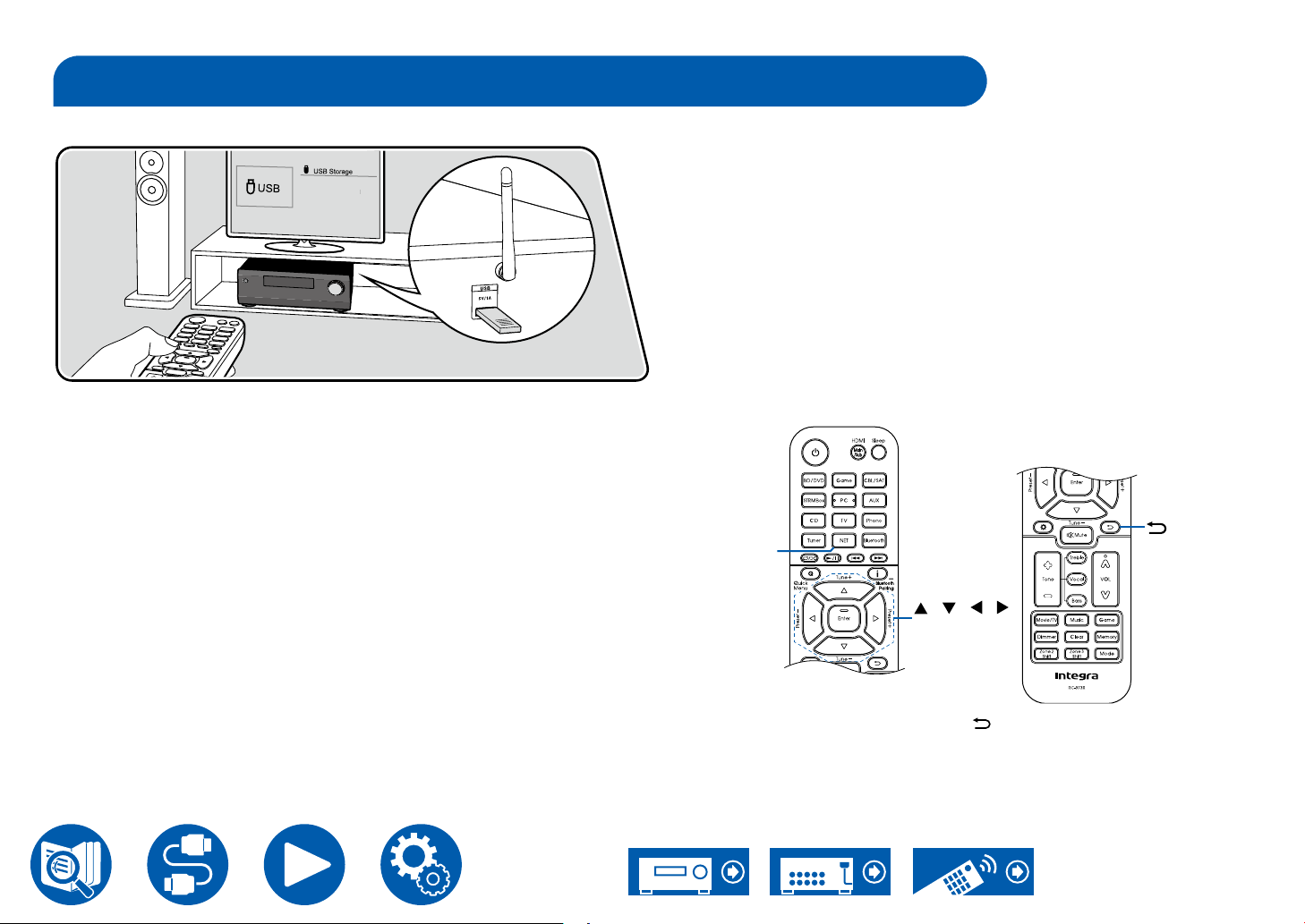
Playing music les saved on a USB storage device
You can play music les stored on a USB storage device.
Perform the following procedure when this unit is on.
1. Switch the input on the TV to the input connected to the unit.
2. Plug your USB storage device with the music les into the USB port on the
rear panel of this unit.
3. Press NET to display the network service list screen.
4. Select "USB" with the cursors, and then press Enter.
• If the "USB" indicator blinks on the display, check whether the USB storage
device is plugged in properly.
• Do not unplug the USB storage device while "Connecting..." is being
displayed on the display. This may cause data corruption or malfunction.
5. Press Enter on the next screen again. The list of folders and music les on
the USB storage device is displayed. Select the folder with the cursors, and
press Enter to conrm your selection.
6. Select the music le with the cursors, and then press Enter to start playback.
Playback
NET
/ / /
Enter
• To return to the previous screen, press .
• Characters that cannot be displayed on this unit appear with "".
• The USB port of this unit complies with the USB 2.0 standard. The transfer
speed may be insufcient for some content you play, and sound interruptions,
etc. may occur.
95
Page 96
• When playing les recorded with VBR (Variable bit-rate), the playback time
may not be displayed correctly.
• This unit supports the gapless playback of the USB storage device in the
following conditions.
When continuously playing WAV, FLAC and Apple Lossless les with the
same format, sampling frequency, the number of channels and quantization
bit rate.
• To display an album title, artist name and album art of a le in WAV format,
make the folder structure and le names as shown below when saving music
les. The album art can be displayed by saving a .jpg le to display on the
screen in the folder of bottom level. Note that a large volume of .jpg le may
take time to be displayed, or may not be displayed.
Folder 1
Artist name
Folder 1-1
Album name
Folder 1-2
Album name
file 1-1
file 2-1
file 3-1
.jpg file
file 1-2
file 2-2
file 3-2
.jpg file
Playback
USB Storage Device Requirements
• This unit can use USB storage devices that comply with the USB mass
storage class standard. Also the format of USB storage devices supports
FAT16 or FAT32 le system format.
• If the USB storage device has been partitioned, each section will be treated
as an independent device.
• Up to 20,000 tracks per folder are supported, and folders can be nested up to
16 levels deep.
• USB hubs and USB storage devices with hub functions are not supported. Do
not connect these devices to the unit.
• If an AC adapter is supplied with the USB storage device, connect the AC
adapter, and use it with a household outlet.
• USB storage devices with security functions are not supported on this unit.
• Media inserted to the USB card reader may not be available in this function.
Furthermore, depending on the USB storage device, proper reading of the
contents may not be possible.
• In use of a USB storage device, our company accepts no responsibility
whatsoever for the loss or modication of data stored on a USB storage
device, or malfunction of the USB storage device. We recommend that you
back up the data stored on a USB storage device before using it with this unit.
• Note that operation is not always guaranteed for all USB storage devices.
96
Page 97
Playback
Music Server
Streaming play of music les stored on PCs or NAS devices connected to the same network as this unit is supported.
• The network servers this unit is compatible with are those PCs with players installed that have the server functionality of Windows Media® Player 12, or NAS that
are compatible with home network functionality. When using Windows Media® Player 12, you need to make the settings beforehand. Note that with PCs, only music
les registered in the library of Windows Media® Player can be played.
Windows Media® Player 12 settings
1. Turn on your PC, and start Windows Media® Player 12.
2. In the "Stream" menu, select "Turn on media streaming" to display a dialog
box.
• If the media streaming is already turned on, select "More streaming
options..." in the "Stream" menu to display the list of playback devices in
the network, and then go to step 4.
3. Click "Turn on media streaming" to display the list of playback devices in the
network.
4. Select this unit in "Media streaming options" and check that it is set to "Allow".
5. Click "OK" to close the dialog.
6. Open the "Stream" menu and conrm that "Allow remote control of my
Player..." is checked.
• Depending on the version of Windows Media® Player, the names of items to
select may differ from the above description.
Playing Back ( →p98)
97
Page 98
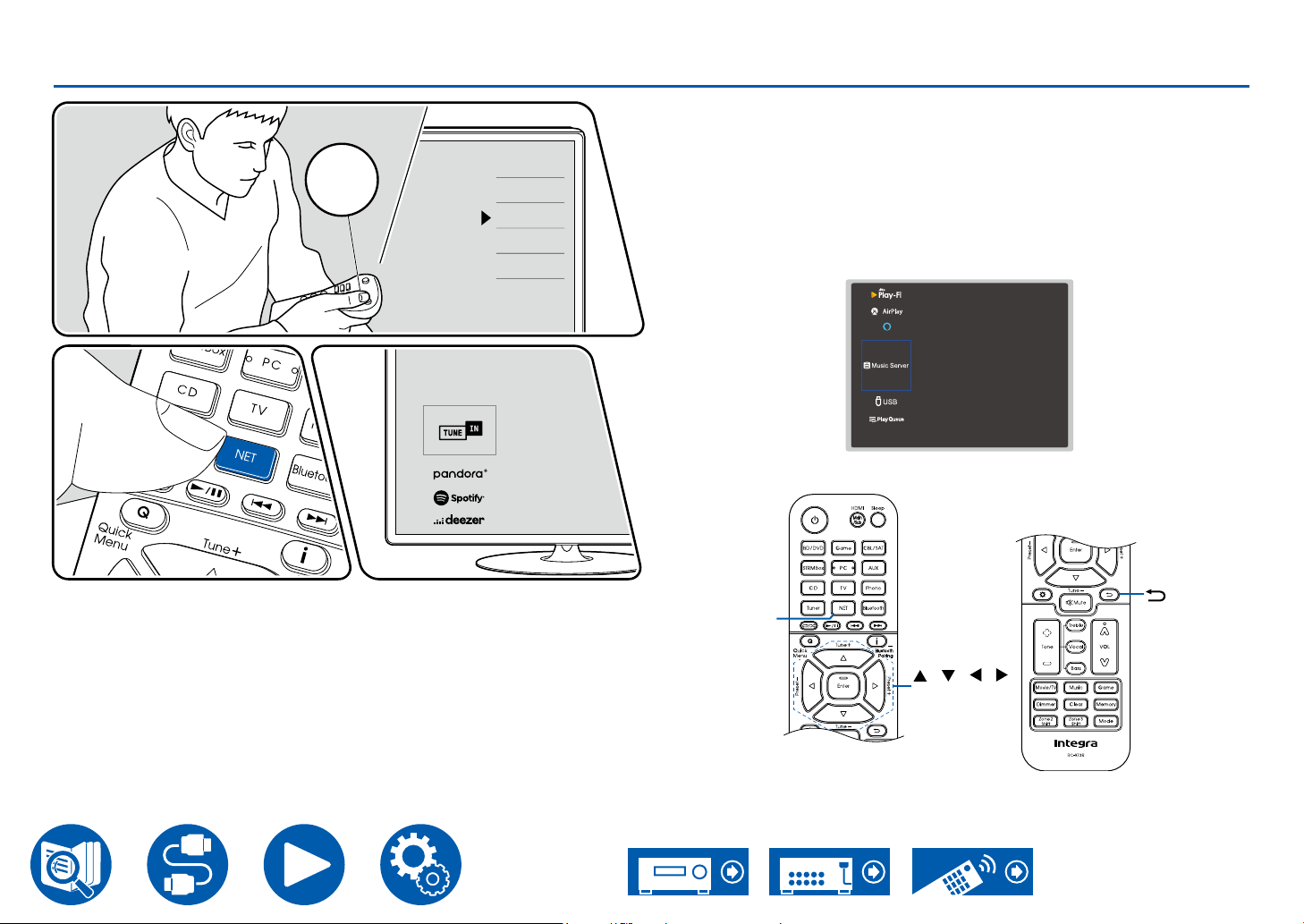
Playing Back
TV
INPUT
TV’s REMOTE
Inputs
TV
HDMI 1
HDMI 2
HDMI 3
Playback
Perform the following procedure when this unit is on.
1. Switch the input on the TV to the input connected to the unit.
2. Start the server (Windows Media® Player 12 or NAS device) containing the
music les to play.
3. Make sure that the PC or NAS is properly connected to the same network as
this unit.
4. Press NET to display the network service list screen.
• If the "NET" indicator on the display blinks, the unit is not properly
connected to the network. Check the connection.
amazonalexa
5. With the cursors, select "Music Server", and then press Enter.
The illustration shows an image.
NET
/ / /
Enter
98
Page 99
6. Select the target server with the cursors, and press Enter to display the items
list screen.
• This unit cannot access pictures and videos stored on servers.
• Depending on the server sharing settings, contents stored on the server
may not be displayed.
7. With the cursors, select the music le to play, and then press Enter to start
playback.
• If "No Item." is displayed on the screen, check whether the network is
properly connected.
• To return to the previous screen, press
• When playing les recorded with VBR (Variable bit-rate), the playback time
may not be displayed correctly.
• For music les on a server, up to 20,000 tracks per folder are supported, and
folders can be nested up to 16 levels deep.
• Depending on the type of media server, the unit may not recognize it, or may
not be able to play its music les.
.
Searching music les to select
If the server you use supports search functions, the following search function
can be used.
Perform the following procedure with available servers displayed using Music
Server.
1. With
2. With
3. With / , select the folder, and press Enter.
4. Input a character string to search for, and press Enter. Then, the search result
5. With
/ , select the server containing music les you want to play, and
select Enter.
/ , select the Search folder, and press Enter. The Search folder
contains the following three folders.
• "Search by Artist": Select this when searching by artist name.
• "Search by Album": Select this when searching by album title.
• "Search by Track": Select this when searching by track title.
is displayed.
/ , select the music les to play, and select Enter.
Playback
Controlling Remote Playback from a PC
You can use this unit to play music les stored on your PC by operating the PC
in your home network. The unit supports remote playback via Windows Media®
Player 12. To use the remote playback function of this unit with Windows Media®
Player 12, it must be congured beforehand. ( →p97)
Remote playback
1. Turn on the power of the unit.
2. Turn on your PC, and start Windows Media
3. Select and right-click the music le to play with Windows Media® Player 12.
• To remotely play a music le on another server, open the target server
from "Other Libraries", and select the music le to play.
4. Select this unit in "Play to" to open the "Play to" window of Windows Media®
Player 12, and start playback on this unit.
• If your PC is running on Windows® 8.1, click "Play to", and select this unit.
If your PC is running on Windows® 10, click "Cast to Device", and select
this unit. Operations during remote playback are possible from the "Play
to" window on the PC. The playback screen is displayed on the HDMIconnected TV.
5. Adjust the volume using the volume bar on the "Play to" window.
• Sometimes, the volume displayed on the remote playback window may
differ from the volume displayed on the display of this unit.
• When the volume is changed on this unit, the value is not reected in the
"Play to" window.
• This unit cannot play music les remotely in the following conditions.
– It is using a network service.
– It is playing a music le on a USB storage device.
• Remote play of FLAC and DSD is not supported.
• Remote playback does not support the gapless playback.
®
Player 12.
99
Page 100
Play Queue
When downloading Integra Control Pro (available on iOS or Android™) to mobile
devices, such as a smartphone and tablet, you can save your favorite playlist
(Play Queue information) among music les stored in the USB storage device
connected to this unit and music les stored in PC or NAS connected to the
same network as this unit, and you can play the music on the playlist. The Play
Queue information is effective until the power cord of this unit is removed from
the outlet. Refer to "Integra Control Pro" ( →p148) for information about the
app.
Adding Play Queue Information
1. Select the "INPUT" input on the application screen, and tap the "USB" icon.
Or, select the "NET" input, and tap the "USB" icon or "Music Server" icon.
(Depending on the model, the icon names may be different.)
Playback
2. Tapping the "+" icon of the track you want to add will open the pop-up to add
the Play Queue information.
3. Touch the "Play Now ", "Play Next " or "Play Last " icon to add the
track to Play Queue.
• If there are no tracks on the Play Queue list, only "Play Now " is
displayed.
Sort and Delete
1. Select the "NET" input, tap the "Play Queue" icon, and enter the Play Queue
service screen.
100
 Loading...