

Page 1
> Before start > Hookup > Setup > Playback > Part Names > Advanced Manual
Troubleshooting | Appendix
AV C o n t r o l l e r
DRC-R1
Hookup
Step1: Speaker Layout ............................................................3
Step2: Connecting Speakers via a Power Amplifier ................9
Step3: Connect the TV ..........................................................12
Step4: Connect the AV Components .....................................14
Step5: Multi-zone Connection ...............................................18
Step6: Connect Other Cables ................................................21
Basic Manual
Setup
Step7: Power On & Initial Setup ............................................22
HDMI Setup ...........................................................................23
Playback
Basic Playback ......................................................................24
Network Functions .................................................................25
Others ....................................................................................26
Part Names
Front Panel ............................................................................29
Rear Panel ............................................................................30
Remote Controller .................................................................31
Display ...................................................................................31
The Basic Manual includes information needed when starting up and
also instructions for frequently used operations. The Advanced Manual
has more detailed information and advanced settings.
Page 2
> Before start > Hookup > Setup > Playback > Part Names > Advanced Manual
Troubleshooting | Appendix
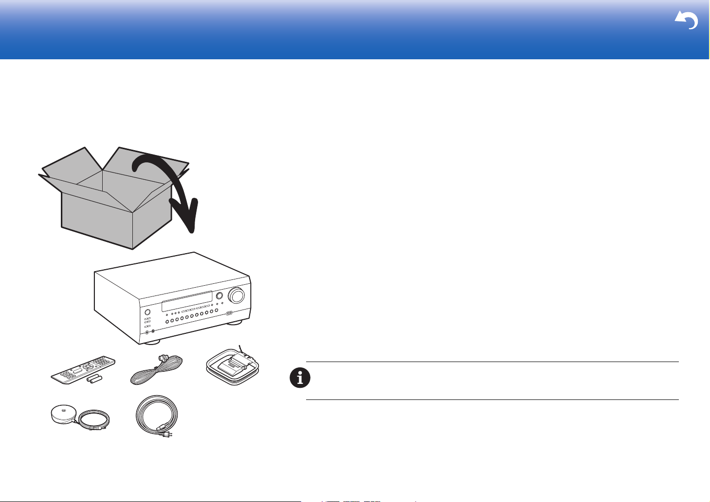
What's in the box
1. Main unit 2. Remote controller (RC-913R) ×1, Batteries (AAA/R03) ×2
3. Indoor FM antenna ×1 4. AM loop antenna ×1 5. Speaker setup microphone ×1
6. Power cord ×1
Glossary
Dolby Atmos
This unit supports playback in the Dolby Atmos format which provides 360e sound placement. Unlike existing
surround systems, Dolby Atmos doesn't rely on channels, but rather enables the accurate placement of sound
objects that have independent motion in a three-dimensional space with even greater clarity. Dolby Atmos is an
optional audio format on Blu-ray Discs and achieves a three-dimensional sound field by introducing a sound field
above the listener.
ARC
The ARC (Audio Return Channel) feature transfers TV audio signals via HDMI cable so that you can play the
1
2
34
56
audio from the TV through this unit. Connection to an ARC compatible TV is complete with one HDMI cable. Refer
to the instruction manual for your TV to see if it supports ARC. (
HDMI CEC functionality
Control features such as linking input switching with the input selector and players conforming to the CEC
standard, switching audio output and volume using the remote controller of a CEC-compliant TV, and
automatically switching this unit to standby when the TV is turned off (
HDMI Standby Through
Video and audio signals from AV components can be transmitted to the TV even if this unit is in standby (
CAUTION: The power cord must be connected only after all other cable connections are completed. We
will not accept responsibility for damage arising from the connection of equipment manufactured by other
companies.
Before start
ÄP12)
ÄP14)
ÄP14)
2
Page 3
> Before start > Hookup > Setup > Playback > Part Names > Advanced Manual
* 1: 22e 〜 30e, * 2: 90e 〜 120e, * 3: 135e 〜 150e
Troubleshooting | Appendix
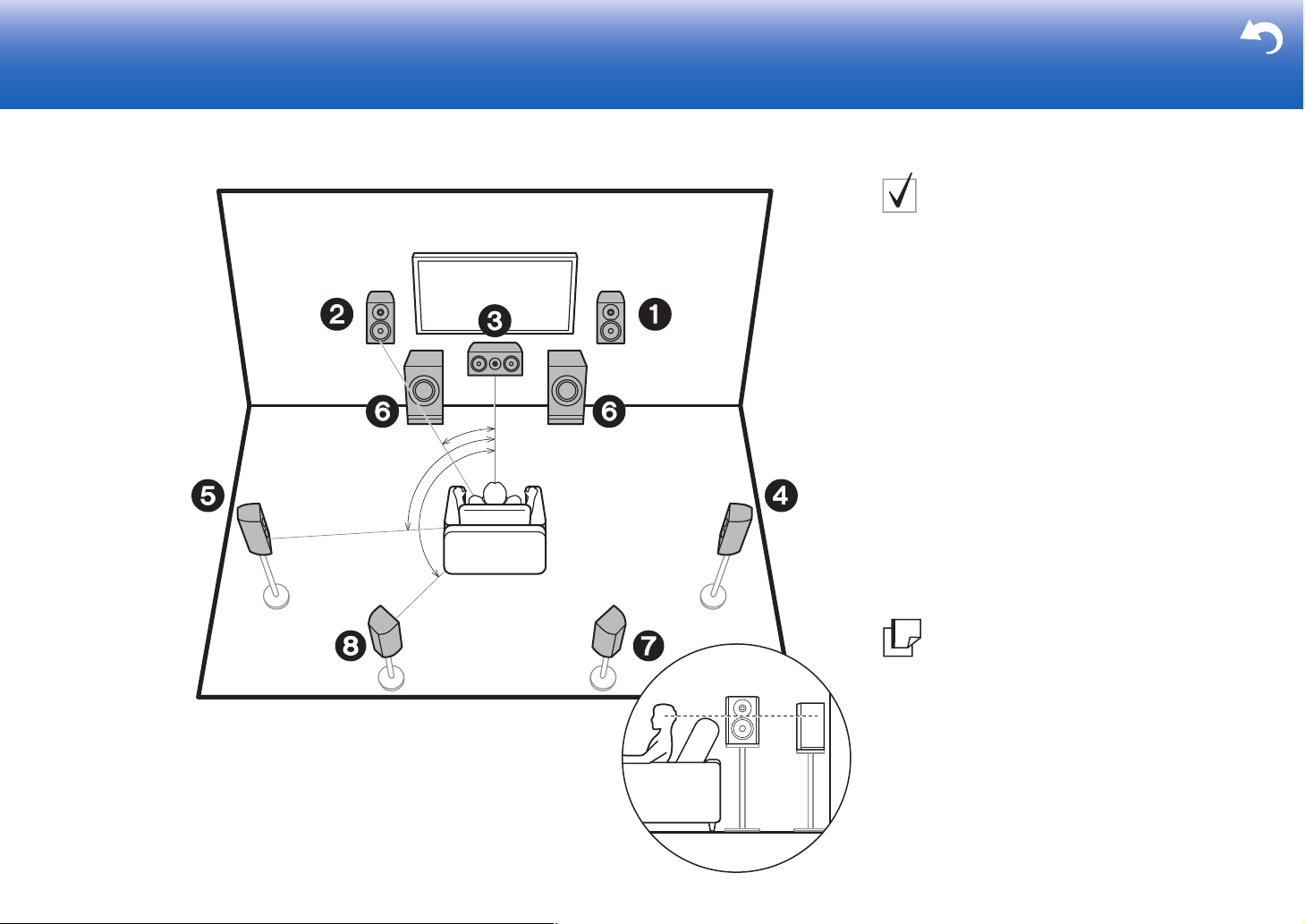
Step1: Speaker Layout
7.1-Channel System
Front speakers output front stereo sound and a center
speaker outputs center sound such as dialogs and vocals.
Surround speakers create back sound field. Powered
subwoofer reproduces bass sounds and creates rich
sound field.
Surround back speakers improve the sense of
envelopment created by the back sound field and provide
a more realistic sound field. Furthermore, by installing
surround back speakers, you can select the Dolby Atmos
listening mode, which realizes the most up-to-date 3D
sound, when the input format is Dolby Atmos.
1
*
2
*
3
*
The front speakers should be positioned at ear height,
while the surround speakers should be positioned just
above ear height. Center speaker should be set up facing
the listening position.
Placing the powered subwoofer between the center
speaker and a front speaker gives you a natural sound
even when playing music.
The optimal positioning is for surround back speakers to
be at ear height.
0 If you are including surround back speakers in the
setup, surround speakers are required.
12
3
45
6
78
Front Speakers
Center Speaker
Surround Speakers
Powered Subwoofer
Surround Back Speakers
Go To "Hookup" (
Hookup
ÄP9)
3
Page 4
> Before start > Hookup > Setup > Playback > Part Names > Advanced Manual
3´ (0.9 m)
or more
3´ (0.9 m)
or more
* 1: 22e 〜 30e, * 2: 90e 〜 120e, * 3: 135e 〜 150e
Troubleshooting | Appendix
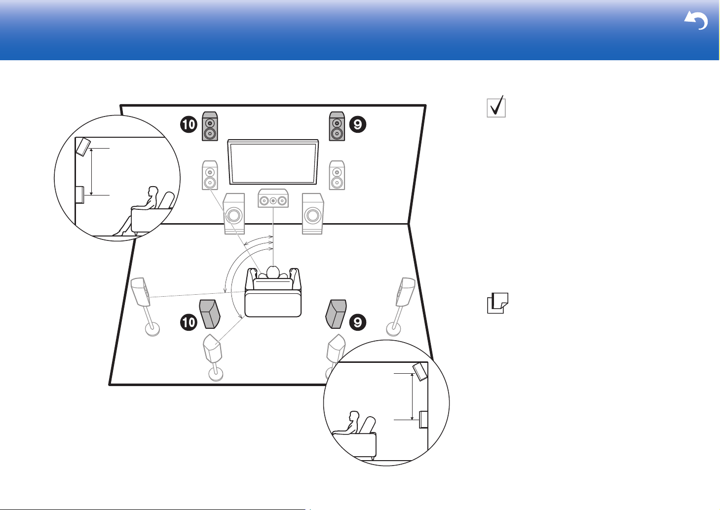
Height Speakers;
Front High Speakers/
Rear High Speakers
These are types of height speakers. Furthermore, by
installing height speakers, you can select the Dolby
Atmos listening mode, which realizes the most up-to-date
3D sound including overhead sounds, when the input
format is Dolby Atmos.
Front high speakers or rear high speakers should be
situated at least 0.9 m higher than the front speakers.
1
*
2
*
Front high speakers should be situated directly above the
front speakers and the distance between the rear high
speakers should match the distance between the front
speakers. Both should be set up facing the listening
position. Note that with height speakers you can install up
to two sets; Height 1 Speaker and Height 2 Speaker.
4
9:
Height Speakers
$
Front High Speakers
$
Rear High Speakers
3
*
Go To "Hookup" (
ÄP9)
Page 5
> Before start > Hookup > Setup > Playback > Part Names > Advanced Manual
* 1: 30e 〜 55e, * 2: 65e 〜 100e, * 3: 125e 〜 150e
Troubleshooting | Appendix
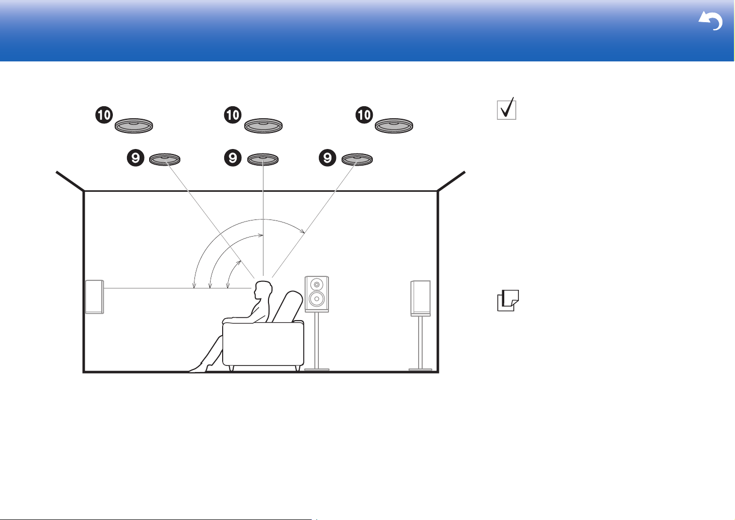
Height Speakers;
Ceiling Speakers
These are types of height speakers. Furthermore, by
installing height speakers, you can select the Dolby
Atmos listening mode, which realizes the most up-to-date
3D sound including overhead sounds, when the input
format is Dolby Atmos.
Fit top front speakers on the ceiling forward of the seating
position, top middle speakers on the ceiling directly above
3
*
2
*
1
*
the seating position, and top rear speakers on the ceiling
behind the seating position. The distance between each
pair should match the distance between the two front
speakers. Note that with height speakers you can install
up to two sets; Height 1 Speaker and Height 2 Speaker.
0 Dolby Laboratories recommends placing this type of
height speakers to obtain the best Dolby Atmos effect.
9:
Height Speakers
$
Top Front Speakers
$
Top Middle Speakers
$
Top Rear Speakers
Go To "Hookup" (
ÄP9)
5
Page 6
> Before start > Hookup > Setup > Playback > Part Names > Advanced Manual
*
1
*
2
*
3
* 1: 22e 〜 30e, * 2: 90e 〜 120e, * 3: 135e 〜 150e
Troubleshooting | Appendix
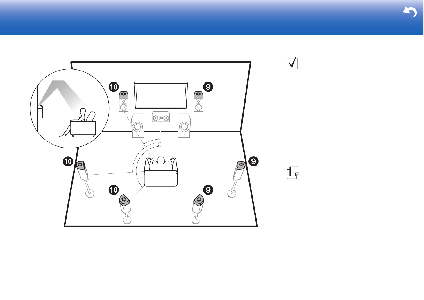
Height Speakers;
Dolby Enabled Speakers
(Dolby Speakers)
These are types of height speakers. Dolby enabled
speakers are special speakers designed to face the
ceiling so that sound is heard after bouncing off the ceiling
so that sound appears to be coming from overhead.
Furthermore, by installing height speakers, you can select
the Dolby Atmos listening mode, which realizes the most
up-to-date 3D sound including overhead sounds, when
the input format is Dolby Atmos.
Place them either above the front speakers or above the
surround speakers or surround back speakers. Note that
with height speakers you can install up to two sets; Height
1 Speaker and Height 2 Speaker.
Go To "Hookup" (
ÄP9)
6
9:
Height Speakers
$
Dolby Enabled Speakers (Front)
$
Dolby Enabled Speakers (Surround)
$
Dolby Enabled Speakers (Surround Back)
Page 7
> Before start > Hookup > Setup > Playback > Part Names > Advanced Manual
*
1
*
2
*
3
* 1: 22e 〜 30e, * 2: 90e 〜 120e, * 3: 135e 〜 150e
Troubleshooting | Appendix
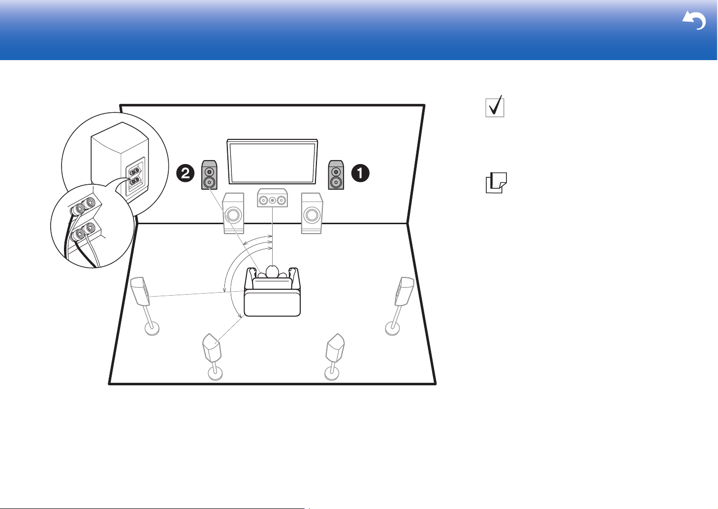
Bi-Amping the Speakers
It is possible to connect front speakers supporting BiAmping to improve quality of the bass and treble. The
effects and placements for speakers are the same as for a
system that doesn't use Bi-Amping speakers.
12
Front Speakers (Bi-Amping)
Go To "Hookup" (
ÄP11)
7
Page 8
> Before start > Hookup > Setup > Playback > Part Names > Advanced Manual
Troubleshooting | Appendix
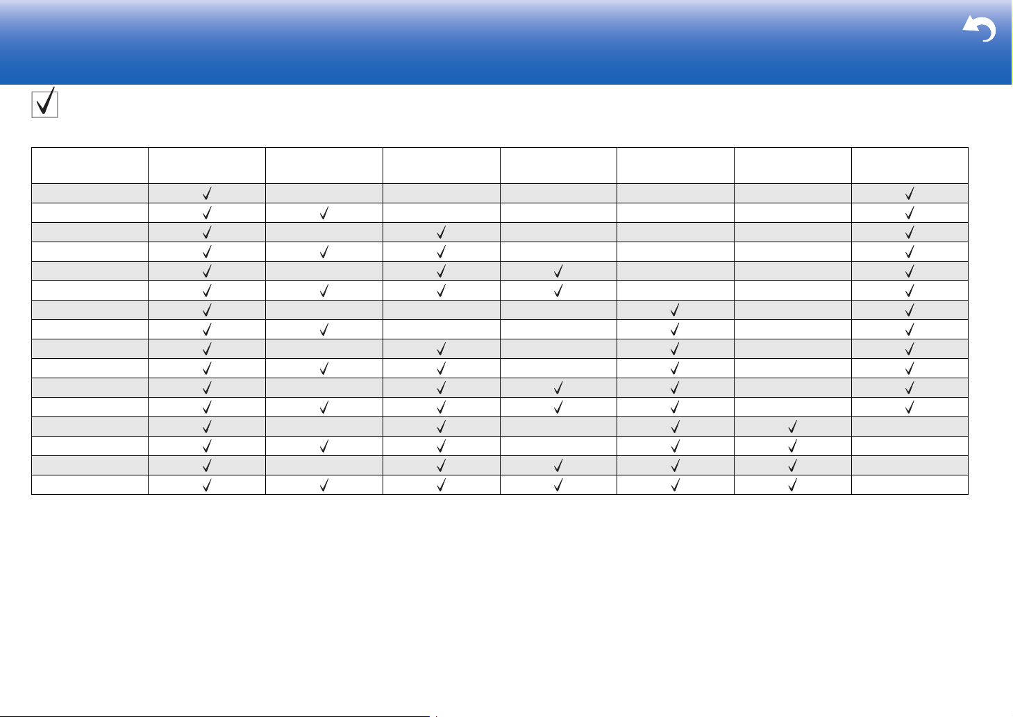
Speaker combinations
In any of the combinations, up to two powered subwoofers can be connected.
Speaker Channels FRONT CENTER SURROUND
2.1 ch
3.1 ch
4.1 ch
5.1 ch
6.1 ch
7.1 ch
2.1.2 ch
3.1.2 ch
4.1.2 ch
5.1.2 ch
6.1.2 ch
7.1.2 ch
4.1.4 ch
5.1.4 ch
6.1.4 ch
7.1.4 ch
SURROUND
BACK
HEIGHT 1 HEIGHT 2 Bi-AMP
*
*
*
*
*
*
Points to note with speaker combinations
* If front speakers are to be Bi-Amping connected, height speakers need to be connected to the HEIGHT
2 jacks.
8
HEIGHT 1/HEIGHT 2
When connecting 2 sets of height speakers, the height speaker combinations you can choose are as follows.
– Height 1 Speaker: Top Middle, Height 2 Speaker: Rear High
– Height 1 Speaker: Front High, Height 2 Speaker: One of Rear High/Top Middle/Top Rear/Dolby Enabled
Speaker (Surround)/Dolby Enabled Speaker (Surround Back)
– Height 1 Speaker: Top Front or Dolby Enabled Speaker (Front), Height 2 Speaker: One of Rear High/Top
Rear/Dolby Enabled Speaker (Surround)/Dolby Enabled Speaker (Surround Back)
When connecting only one set of height speakers, select one type of height speakers from the types
available.
Page 9
> Before start > Hookup > Setup > Playback > Part Names > Advanced Manual
2
1
ᴧᴧ
Subwoofer with built-in
amplifier
Power amplifier
Troubleshooting | Appendix
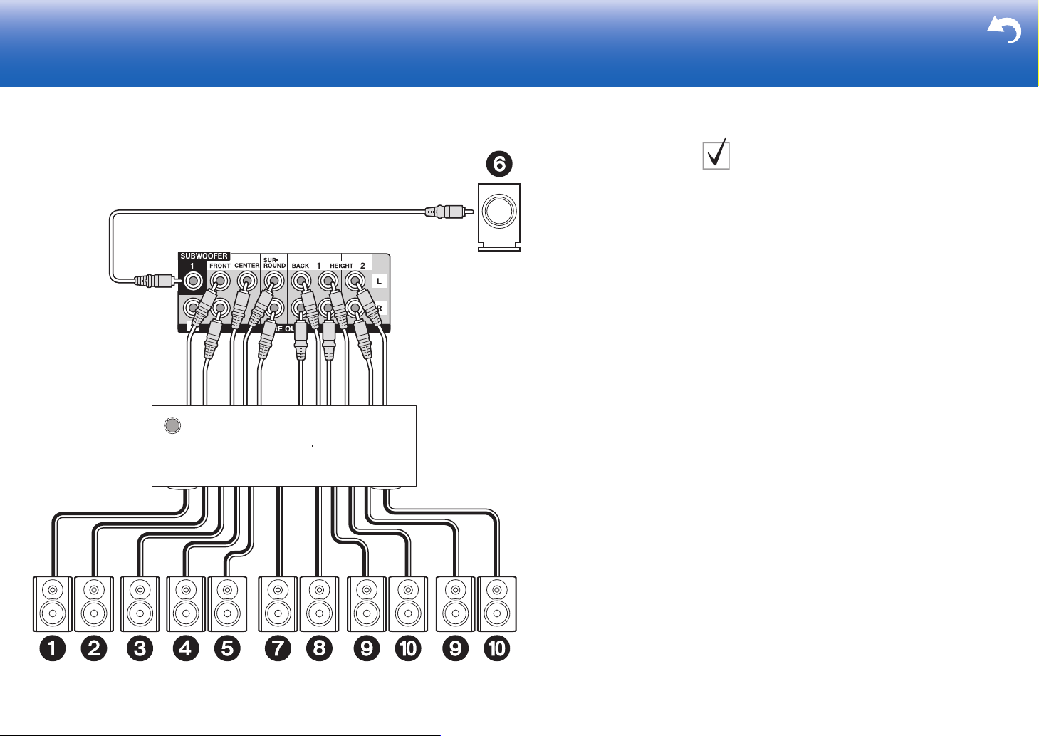
Step2: Connecting Speakers via a Power Amplifier
PRE OUT (RCA) Jacks
Use an analog audio cable to connect the power amplifier
to the PRE OUT (RCA) jacks on this unit. For details on
how to connect the speakers and the power amplifier,
refer to the instruction manual of the power amplifier.
0 If your subwoofer does not have a built-in amplifier,
connect via a power amplifier.
0 Set the crossover frequency, speaker distance and
other settings on this unit.
* Depending on the combination of speakers, you may need to
connect to other jacks. See "Points to note with speaker
combinations" (ÄP8) for details.
1 Analog audio cable, 2 Subwoofer cable
9
Page 10
> Before start > Hookup > Setup > Playback > Part Names > Advanced Manual
1
ᴧᴧ
Subwoofer with
built-in amplifier
Power amplifier
Troubleshooting | Appendix
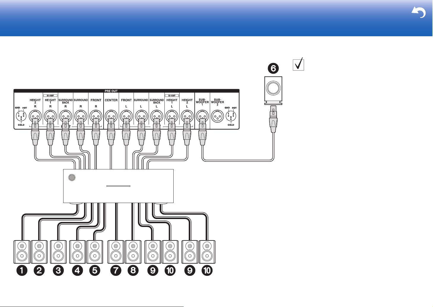
PRE OUT (XLR) Jacks
Use a balanced XLR cable to connect the powered
amplifier to the PRE OUT (XLR) jacks on this unit. For
details on how to connect the speakers and the amplifier,
refer to the instruction manual of the power amplifier.
0 If your subwoofer does not have a built-in amplifier,
connect via a power amplifier.
0 Set the crossover frequency, speaker distance and
other settings on this unit.
* Depending on the combination of speakers, you may need to
connect to other jacks. See "Points to note with speaker
combinations" (ÄP8) for details.
10
1 XLR balanced cable
Page 11
> Before start > Hookup > Setup > Playback > Part Names > Advanced Manual
+−+− +− +−
LRLR
FRONT HEIGHT
1
For highfrequency
For lowfrequency
Power amplifier
Troubleshooting | Appendix
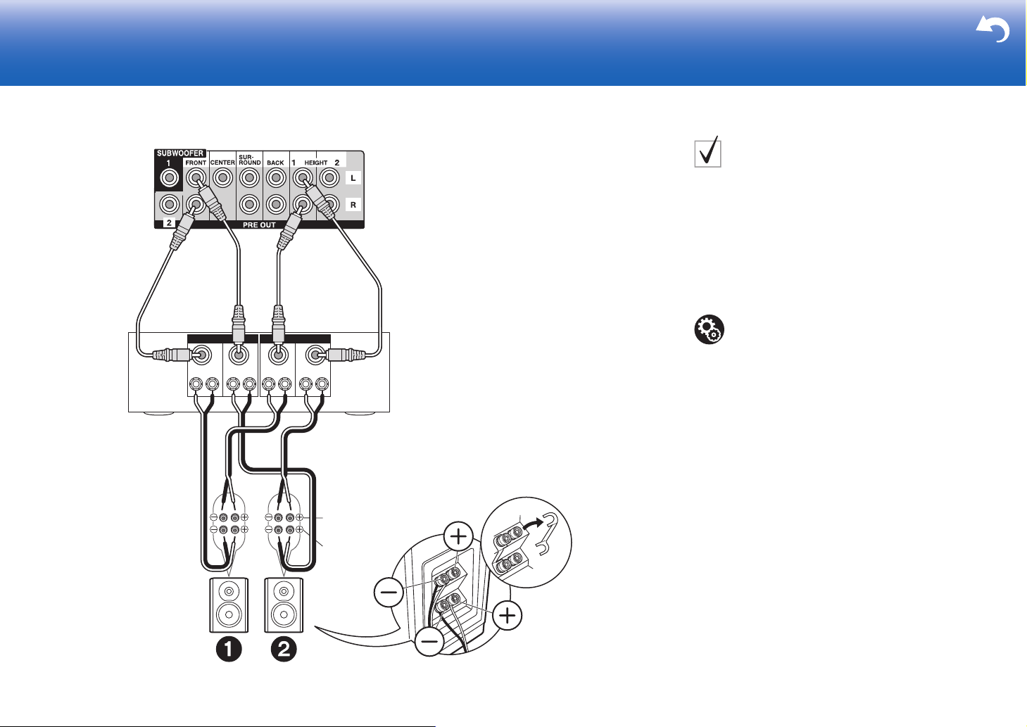
Connections with BiAmping speakers
The illustration at left shows an example of connection
using the PRE OUT (RCA) jacks. Refer to the illustration
at left also when connecting using the PRE OUT (XLR)
jacks. Both connections use the FRONT jacks and
HEIGHT 1 jacks. Make sure you remove the jumper bar
fitted between the woofer jacks and tweeter jacks of the
front speakers. In case of Bi-Amping connection, refer to
the instruction manual of your speakers.
Setup
0 Bi-Amping connection requires you to change
some settings. Select "Yes" in "Bi-Amp" in "1.
AccuEQ Room Calibration" (
Setup.
ÄP22) in the Initial
1 Analog audio cable
11
Page 12
> Before start > Hookup > Setup > Playback > Part Names > Advanced Manual
HDMI IN (ARC)
1
TV
Troubleshooting | Appendix
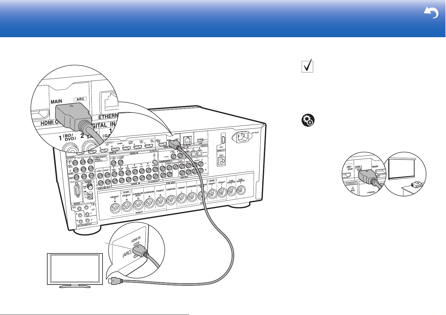
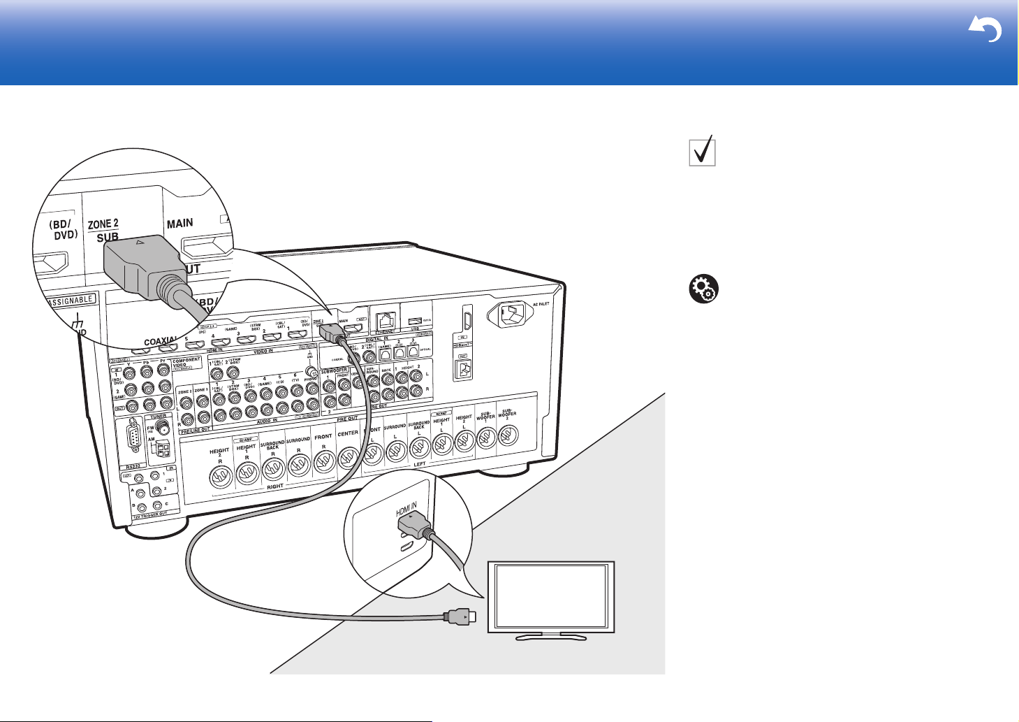
Step3: Connect the TV
TV-1 (ARC TV)
This describes the connections for a TV that supports the
ARC (Audio Return Channel) feature. By connecting with
a single HDMI cable, you can not only output the video
input to this unit to the TV, but you can also play the sound
from the TV through this unit. Choose an HDMI IN jack on
the TV that supports ARC when connecting.
Setup
0 Settings are required to use the ARC function.
Select "Yes" in "5. Audio Return Channel" (
in the Initial Setup.
0 Please refer to the TV's operation manual for
directions on connections and setup for the TV.
ÄP23)
12
1 HDMI cable
Another TV or projector can be connected to the HDMI OUT SUB
jack. This jack does not support ARC. For details about how to
output video from the HDMI OUT SUB jack (ÄP24)
Page 13
> Before start > Hookup > Setup > Playback > Part Names > Advanced Manual
12
TV
Troubleshooting | Appendix
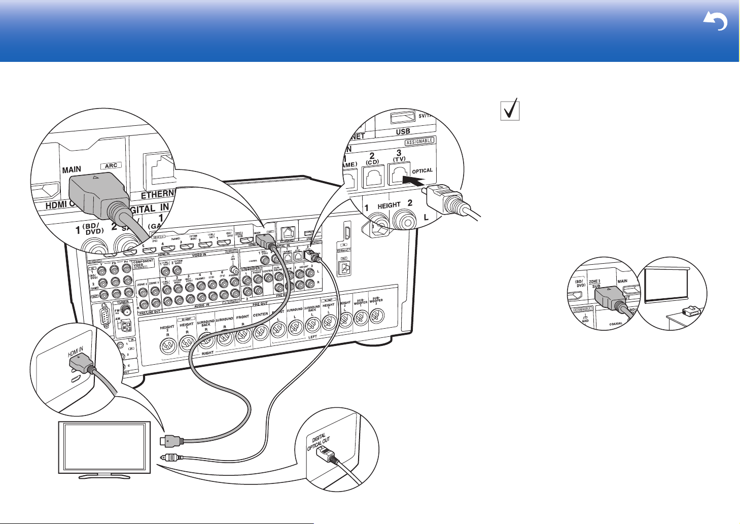
TV-2 (Non-ARC TV)
This describes the connections for a TV that does not
support the ARC (Audio Return Channel) feature. By
connecting with both an HDMI cable and a digital optical
cable, you can not only output the video input to this unit
to the TV, but you can also play the sound from the TV
through this unit.
If the TV doesn't have a DIGITAL OPTICAL OUT jack, use
an analog audio cable and connect the TV's ANALOG
AUDIO OUT jack to the AUDIO IN TV jack on this unit.
0 Connection with a digital optical cable is not necessary
if you will watch TV through a device such as a cable
set-top box (that is, not use a tuner built into the TV)
that you have connected to the INPUT jack on this unit.
1 HDMI cable, 2 Digital optical cable
Another TV or projector can be connected to the HDMI OUT SUB
jack. This jack does not support ARC. For details about how to
output video from the HDMI OUT SUB jack (ÄP24)
13
Page 14
> Before start > Hookup > Setup > Playback > Part Names > Advanced Manual
BD/DVD
GAME
1
Cable/Satellite set-top
box
Streaming media
player
Troubleshooting | Appendix
Step4: Connect the AV Components
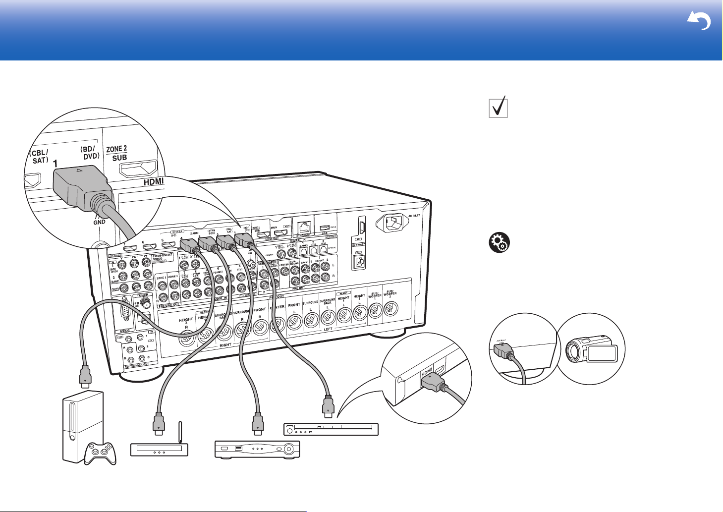
HDMI AV Components
This is an example of connection with an AV component
that has an HDMI jack. With connection to an AV
component that conforms with the CEC (Consumer
Electronics Control) standard, you can use features such
as the HDMI CEC feature that links with the input selector,
and the HDMI Standby Through feature which allows you
to play video and audio from AV components on the TV
even when this unit is in standby mode.
0 To play 4K or 1080p video, use a high speed HDMI
cable. Further, to enjoy HDCP2.2 compatible video,
connect to the HDMI IN1 to IN5 jacks.
Setup
0 HDMI setup (
CEC and HDMI Standby Through features. Make
settings after all connections are complete.
0 To enjoy digital surround sound including Dolby
Digital, audio output should be set to "Bitstream
output" on the connected Blu-ray Disc player or
other device.
ÄP23) is required to use the HDMI
14
1 HDMI cable
You can connect a device such as a video camera to the AUX
Input HDMI jack on the front panel.
Page 15
> Before start > Hookup > Setup > Playback > Part Names > Advanced Manual
OR
1
23
BD/DVD
Troubleshooting | Appendix
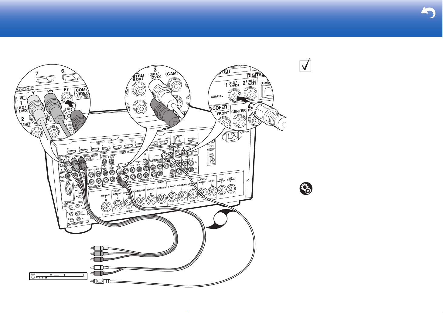
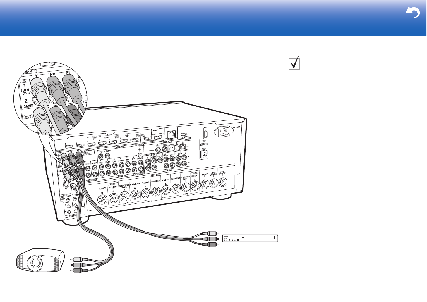
Non-HDMI AV Components
This is an example of connection with an AV component
that does not have an HDMI jack. Make the connections
to the AV component to match the jacks it has. When
video input connection is to the BD/DVD jack, the audio
input connection should also be to the BD/DVD jacks, and
so on, so that you connect the video input jacks to the
jacks with the same name as the audio input jacks. Note
that video signals input to the VIDEO IN jack or the
COMPONENT VIDEO IN jacks will be converted to HDMI
video signals and then output from the HDMI OUT jack.
0 To enjoy digital surround playback in formats such as
Dolby Digital, you need to make a connection for audio
signals with a digital coaxial cable or digital optical
cable.
0 It is possible to change assignment of the input jacks
you see in the illustration at left, so you can also
connect to any jack other than BD/DVD. For details,
see the Advanced Manual.
Setup
0 The COMPONENT VIDEO IN jacks are
compatible only with 480i or 576i resolution. When
you input video signals to the COMPONENT
VIDEO IN jacks, set the output resolution of the
player to 480i or 576i. Select interlace if there is no
option for 480i, etc. If your player does not support
480i or 576i output, use the VIDEO IN jack.
0 To enjoy digital surround sound including Dolby
Digital, audio output should be set to "Bitstream
output" on the connected Blu-ray Disc Player or
other device.
1 Component video cable, 2 Digital coaxial cable, 3 Analog audio cable
15
Page 16
> Before start > Hookup > Setup > Playback > Part Names > Advanced Manual
OR
CD
2
1
Turnta ble
Troubleshooting | Appendix
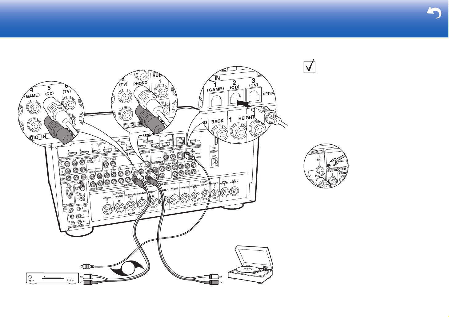
Audio Components
Example of a connection with an Audio Component.
Connect a CD player using a digital optical cable or
analog audio cable. You can also connect a turntable that
has an MM-type cartridge to the PHONO jack.
0 If the turntable has a built-in audio equalizer, connect it
to an AUDIO IN jack other than the PHONO jack.
Further, if the turntable uses an MC type cartridge,
install an audio equalizer compatible with the MC type
cartridge between the unit and the turntable, then
connect to any AUDIO IN jack other than the PHONO
jack.
If the turntable has a ground wire, connect it to the GND terminal
of this unit.
16
1 Digital optical cable, 2 Analog audio cable
Page 17
> Before start > Hookup > Setup > Playback > Part Names > Advanced Manual
1
BD/DVD
Projector, etc.
Troubleshooting | Appendix
Component Video Monitor
Use a component video cable to connect a TV or projector
that has component video input jacks rather than an
HDMI input jack. To output video from the COMPONENT
VIDEO OUT jacks, you must connect the external AV
components using a component video cable.
1 Component video cable
17
Page 18
> Before start > Hookup > Setup > Playback > Part Names > Advanced Manual
TV
ZONE2
MAIN ROOM
1
Troubleshooting | Appendix
Step5: Multi-zone Connection
ZONE 2 TV
You can enjoy content from a Blu-ray Disc player on a TV
equipped with an HDMI input jack in the separate room
(ZONE 2) by playing a Blu-ray Disc player in the main
room (where this unit is located), or play the content from
another AV component. Only the video from devices
connected to the HDMI IN1 to IN5 jacks can be played on
the TV in the separate room.
Setup
0 Settings are required in Initial Setup, "4. Multi
Zone Setup" (
The audio from externally connected AV
0
components can only be played in ZONE 2 when the
audio is analog or 2ch PCM audio.
necessary to convert the audio output of the AV
component to PCM output.
ÄP23) to enjoy this feature.
It may also be
18
1 HDMI cable
Page 19
> Before start > Hookup > Setup > Playback > Part Names > Advanced Manual
ZONE2
ZONE 2 PRE/LINE OUT
1
MAIN ROOM
LINE
IN
Troubleshooting | Appendix
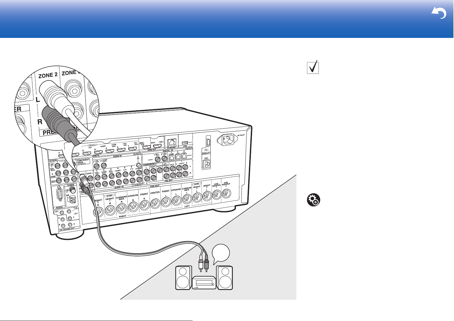
ZONE 2 PRE/LINE OUT
You can enjoy audio in the separate room by, for example,
playing a Blu-ray Disc player in the main room (where this
unit is located) and listening to internet radio in the
separate room (ZONE 2).
Connections with an AV component
Connect with HDMI IN 1 to 5 if you want to output an
external AV component to ZONE 2. If the AV component
doesn't have an HDMI jack, connect using a digital optical
cable, digital coaxial cable, or analog audio cable.
ZONE 2 PRE/LINE OUT
It is possible to play 2 ch sources in a separate room while
sources with a maximum of 11.1 ch are being played in
the main room. Connect the ZONE 2 PRE/LINE OUT
jacks of the unit and the LINE IN jacks of the pre-main
amplifier or the power amplifier in a separate room with an
analog audio cable.
1 Analog audio cable
Setup
0 Settings are required in Initial Setup, "4. Multi
Zone Setup" (
0 The audio from externally connected AV
components can only be played in ZONE 2 when
the audio is analog or 2ch PCM audio. If you have
connected to this unit with an HDMI cable or digital
optical/coaxial cable, may be necessary to convert
the audio output of the AV component to PCM
output.
ÄP23) to enjoy this feature.
19
Page 20
> Before start > Hookup > Setup > Playback > Part Names > Advanced Manual
1
MAIN ROOM
LINE
IN
ZONE3
ZONE 3 PRE/LINE OUT
BD/DVD
Troubleshooting | Appendix
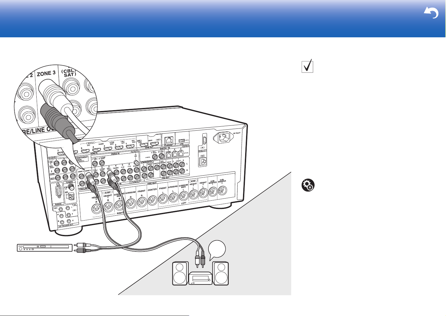
ZONE 3 PRE/LINE OUT
Along with the main room and ZONE 2, you can also
enjoy audio in yet another room (ZONE 3).
Connections with an AV component
To output the audio of an external AV component to ZONE
3, connect using an analog audio cable. Output to ZONE
3 is not possible when you connect with an HDMI cable or
digital optical/coaxial cable.
ZONE 3 PRE/LINE OUT
It is possible to play 2 ch sources in a separate room while
sources with a maximum of 11.1 ch are being played in
the main room. Connect the ZONE 3 PRE/LINE OUT
jacks of the unit and the LINE IN jacks of the pre-main
amplifier or the power amplifier in a separate room with an
analog audio cable.
Setup
0 Settings are required in Initial Setup, "4. Multi
Zone Setup" (
ÄP23) to enjoy this feature.
20
1 Analog audio cable
Page 21
> Before start > Hookup > Setup > Playback > Part Names > Advanced Manual
1
3
4
1
2
(North American
models)
(Australian models)
Troubleshooting | Appendix
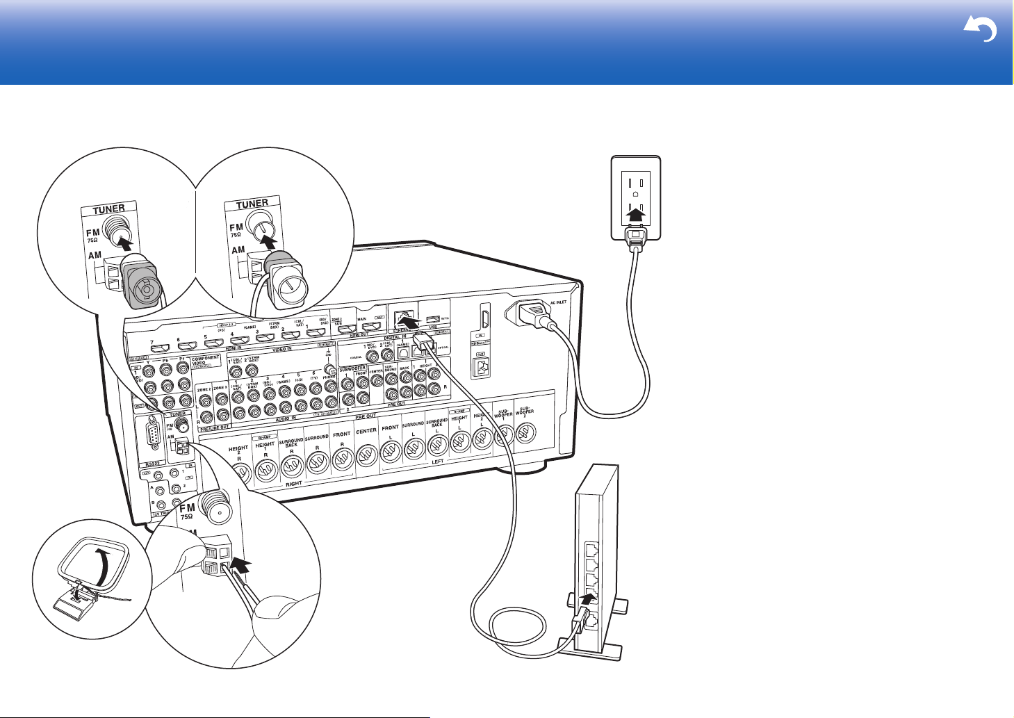
Step6: Connect Other Cables
Antenna Hookup
Move the antenna around while playing the radio to find
the position with the best reception. Use a thumb tack or
similar to attach the indoor FM antenna to a wall.
Network Hookup
Connect this unit to the network using wired LAN. You can
enjoy network features such as internet radio, Music
Server, and AirPlay by connecting the unit to the network.
If you connect by wired LAN, connect with an Ethernet
cable to the ETHERNET port as shown in the illustration.
Power Cord Hookup
This unit includes removable power cords. Connect the
power cord to the power outlet after completing all other
connections. Connect the power cord to AC INLET of the
unit and then connect to the outlet. Always disconnect the
outlet side first when disconnecting the power cord.
1 AM loop antenna, 2 Indoor FM antenna, 3 Ethernet cable, 4 Power cord
21
Page 22
> Before start > Hookup > Setup > Playback > Part Names > Advanced Manual
Troubleshooting | Appendix
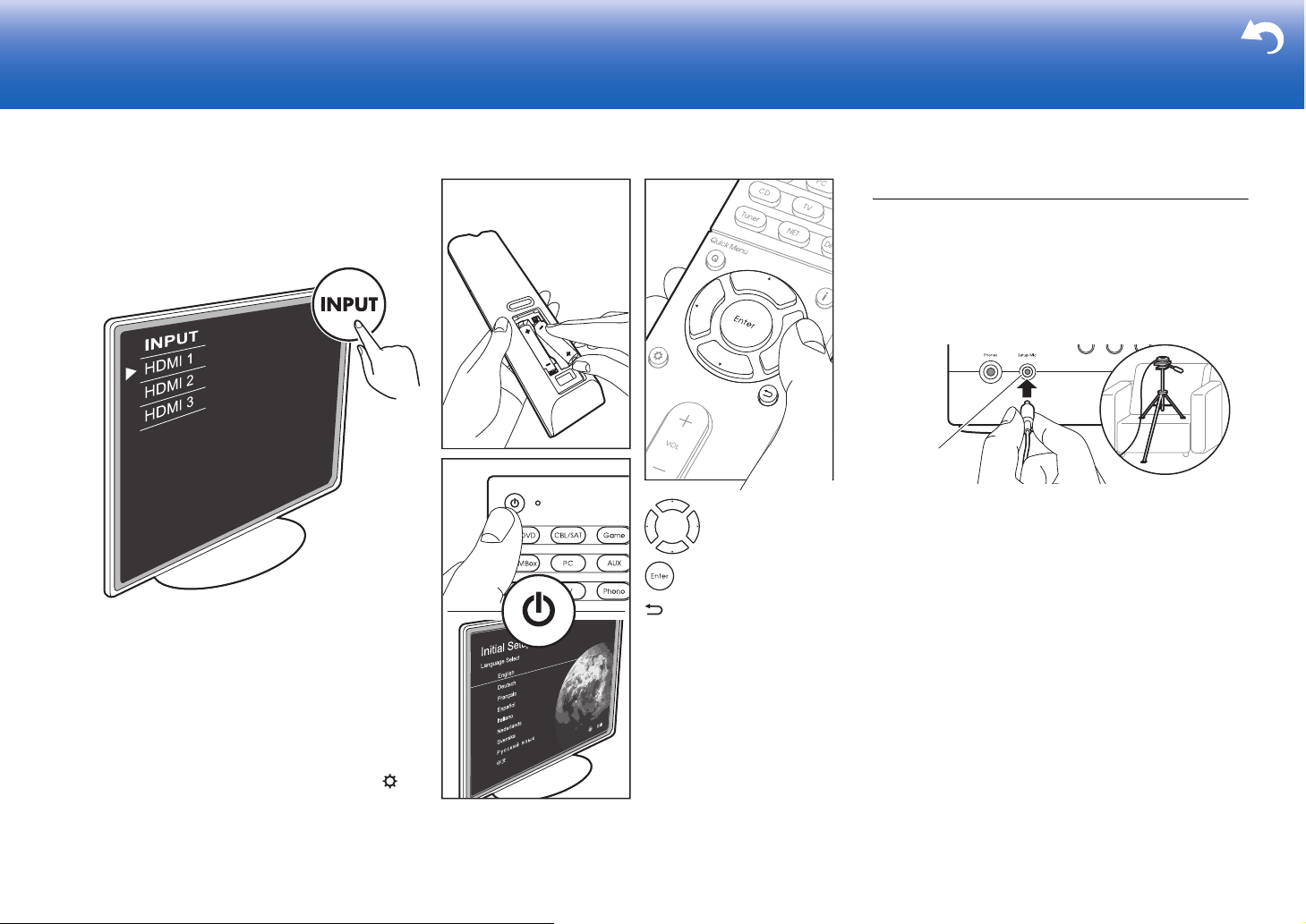
Step7: Power On & Initial Setup
1. AccuEQ Room Calibration
Place the supplied speaker setup microphone in the
listening position, measure the test tones emitted by the
speakers, then the unit automatically sets the optimum
volume level for each speaker, the crossover frequencies,
and the distance from the listening position. This also
enables correction of distortion caused by the acoustic
environment of the room.
Setup Mic
0 When putting the speaker setup microphone on a tripod,
: Selection
: OK
: Return
Initial Setup starts automatically
Switch the input on the TV to that assigned to the unit.
When you turn the unit on for the first time, Initial Setup is
automatically shown on the TV to enable you to make
settings required for startup using simple operations
following onscreen guidance.
0 If you terminate the procedure on the way or want to
change a setting made during Initial Setup, press on
the remote controller, select "8. Miscellaneous" – "Initial
Setup", and press Enter.
refer to the illustration when putting it in place.
0 Set the subwoofer volume to more than halfway.
0 Calibration takes between 3 and 12 minutes to be
completed. The speakers emit the test tone at high
volume during measurement, so be careful of your
surroundings. Keep the room as quiet as possible during
measurement.
0 When using THX certified speakers, THX recommends
setting the crossover frequency to "80Hz(THX)". It is also
recommended to manually adjust the settings for each
speaker to suit the specific characteristics of each room.
Setup
22
Page 23
> Before start > Hookup > Setup > Playback > Part Names > Advanced Manual
6-1 HDMI
HDMI CEC
HDMI Standby Through
Audio TV Out
Audio Return Channel
Auto Lip Sync
On
Auto(Eco)
Auto
Auto
On
Troubleshooting | Appendix
HDMI Setup
2. Source Connection
Check that each input source is connected correctly. Follow
the guidance, select the input you want to confirm, start
play of the selected player, and confirm that the images
appear on the TV and that sound is played.
3. Network Connection
You can check the network connection status.
0 A confirmation screen asking you to agree to the privacy
policy is displayed during network setting. Select "Yes"
and press Enter to indicate agreement.
4. Multi Zone Setup
Make these settings to enjoy video and audio in a room
other than the main room (ZONE 2/ZONE 3).
Select "with External Premain Amplifier" when connecting a
pre-main amplifier in the separate room. Select "with
External Power Amplifier" when connecting a power
amplifier.
If you are going to be connecting a TV in the separate room
(ZONE 2), then when "Would you be using TV in 2nd
room?" is displayed, select "Yes".
5. Audio Return Channel
If you have connected a TV that supports ARC, select
"Yes". This unit's ARC setting turns on and you can listen to
the TV's audio through this unit.
0 If you select "Yes", the HDMI CEC function is enabled
and power consumption increases during standby.
HDMI CEC
Make this setting to enable the control feature for devices
complying with the CEC standard. This is set to on
automatically if you have selected "Yes" in "5. Audio Return
Channel" in the Initial Setup.
Press the button on the remote controller to set "6.
Hardware" – "HDMI" – "HDMI CEC" to "On" on the TV
screen. Also enable the CEC control feature on the CEC
device you have connected.
HDMI Standby Through
Even if this unit is in standby, the input signals from AV
components are transmitted to the TV.
0 "Auto" / "Auto (Eco)": Select one of these settings
when connected AV components comply with the CEC
standard. Irrespective of the input selector selected
immediately before switching the unit to standby, you can
transmit the input signals from AV components to the TV.
Select "Auto (Eco)" if the TV is also CEC-compliant. You
can reduce power consumption in standby mode.
0 Input selector names for "BD/DVD", etc.: You can
transmit the input signals from the set input selector to
the TV. It can be selected when "HDMI CEC" is set to
"Off".
0 "Last": You can transfer the input signals of the input
selector selected immediately prior to the unit being
switched to standby. It can be selected when "HDMI
CEC" is set to "Off".
To exit the settings, press .
23
Page 24
> Before start > Hookup > Setup >Playback > Part Names > Advanced Manual
c
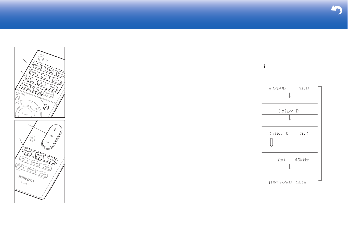
b
Input source & volume
Listening mode
Signal format
Sampling frequency
Input signal resolution
The display changes few
seconds later.
Troubleshooting | Appendix
Basic Playback
a
d
24
AV Component Playback
1. Switch the input on the TV to that assigned to
the unit.
2. Press the input selector (a) on the remote
controller with the same name as the jack to
which you connected the player to switch the
input.
For example, press BD/DVD to play the
player connected to the BD/DVD jack. Press
TV to listen the TV's sound.
0 When the CEC link function works, the
input switches automatically when you
have connected a CEC compliant TV and
player to this unit using HDMI connection.
3. Start play on the player.
4. Use VOL+/– (b) to adjust the volume.
When a TV is connected to the HDMI OUT
SUB jack
Press Q on the remote controller to display the
Quick Menu, and set "Other" – "HDMI Out" to
either "SUB" or "MAIN+SUB".
Listening Mode
This unit is equipped with a variety of listening
modes, and you can select the optimum
listening mode for movies, TV, music, and
games by repeatedly pressing the Movie/TV,
Music, and Game buttons (c). For details on the
listening modes, see the Advanced Manual.
This section introduces some of the popular
modes.
Dolby Digital/DTS modes
When the input signal is a digital surround
format such as Dolby Digital or DTS, you can
select the listening mode that suits the input
signal. Dolby Digital is displayed for Dolby
Digital and DTS-HD Master Audio is displayed
for DTS-HD Master Audio. The output is Stereo
for 2-channel input signals.
Direct
This listening mode can be selected for all input
signals. It shuts down processing that affects
sound quality to deliver a playback sound quality
closer to sources. Speakers play the sound field
according to the number of channels in the input
signal, so there would be output from only the
front speakers for a 2 ch signal, for example.
Dolby Surround/DTS Neural:X
These listening modes allow you to expand the
playback signal to a maximum of 11 channel to
suit the connected speaker configuration when
the input signal is 2 channels or 5.1 channels.
THX surround modes
Multiple surround speakers are installed in
movie theaters so that the moviegoer is
enveloped in a natural surround sound. Even
with just two surround speakers, the THX
Cinema mode achieves, with the high-quality
technology developed by THX, the same kind of
breadth of sound you would get in a movie
theater along with the natural flow of timbre with
the sound field towards the front. Also available
are modes such as THX Music and THX
Games.
Original surround modes
You can select listening modes such as the All
Ch Stereo mode where a stereo image is played
from both the front and the rear, and Orchestra
(only with the Music button) which is best for
playback of classical and opera pieces.
The listening mode last selected for the source
is remembered for each of the Movie/TV, Music,
Game buttons. If content you play is not
supported by the listening mode you selected
last, the listening mode that is standard for that
content is selected automatically.
Press (d) repeatedly to switch the display of
the main unit in order of:
Playback
Page 25
> Before start > Hookup > Setup >Playback > Part Names > Advanced Manual
Troubleshooting | Appendix
Network Functions
Network Services
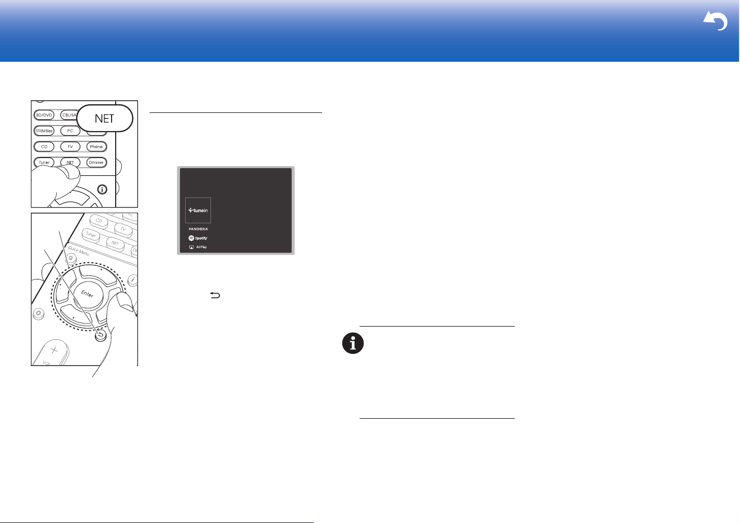
1. Switch the input on the TV to that assigned to
the unit.
2. Press NET to display the network service list
screen.
a
b
3. Select the item with the cursors of the remote
controller and press Enter to confirm your
selection (a). To return to the previous
screen, press (b).
Internet Radio
When this unit is connected to a network, you
can listen to TuneIn or other preregistered
Internet radio services. After selecting the
desired service, follow the on-screen
instructions, using the cursors to select radio
stations and programs, then press Enter to play.
Play starts when 100% is displayed for
buffering.
Music Server
You can play music files stored on homenetwork compliant PCs or NAS devices
connected to the same network as this unit.
Select the server with the cursors, select the
desired music file and press Enter to start
playback. Play starts when 100% is displayed
for buffering.
0 This unit is compatible with Windows Media
®
Player 11 or 12 network servers or NAS that
are compatible with home network
functionality. You may need to make some
settings in advance to use Windows Media
Player 11 or 12. Enable media streaming for
this player in Windows Media
details, see the Advanced Manual.
USB
Play music files on a USB storage device.
Connect the USB storage device to the USB
jack on the rear of the unit, select USB in the list
of network services, and press Enter to confirm.
Select the desired folder or music file with the
cursors, and press Enter to confirm and start
playback.
0 Operation cannot be guaranteed for all USB
storage devices.
0 This unit can use USB storage devices that
comply with the USB mass storage device
class standard. The unit is also compatible
with USB storage devices using the FAT16 or
FAT32 file system formats.
Notes:
0 Network services become selectable after the
network starts up even if they cannot be
selected first.
0 Functionality may be introduced by firmware
updates and service providers may cease
services, meaning that some network services
and content may become unavailable in the
future. Furthermore, available services may
vary depending on your area of residence.
®
Player. For
®
25
Page 26

> Before start > Hookup > Setup >Playback > Part Names > Advanced Manual
a
b
c
d
e
Troubleshooting | Appendix
Others
AirPlay
You can enjoy the music files on an iPhone®, iPod touch®,
®
connected to the same access point as this unit.
or iPad
0 Update the OS version on your iOS device to the latest
version.
1. Connect the iOS device to the access point.
2. Press NET.
3. Tap the AirPlay icon in the control center of the iOS
device and select this unit from the list of devices
displayed, and tap "Done".
4. Play the music files on the iOS device.
0 If "6. Hardware" – "Power Management" – "Network
Standby" is "On" in the Setup menu displayed by
pressing the button on the remote controller, then
iPhone
IntegraDRC-XX
once AirPlay starts, this unit switches on automatically
and the "NET" input source is selected.
0 Due to the characteristics of AirPlay wireless
technology, the sound produced on this unit may slightly
be behind the sound played on the AirPlay-enabled
device.
You can also play back music files on the computer with
iTunes (Ver. 10.2 or later). Before operation, make sure
this unit and the PC are connected to the same network,
then press NET on this unit. Next, click the AirPlay icon
in iTunes, select this unit from the list of devices displayed,
and start play of a music file.
Listening To the Radio
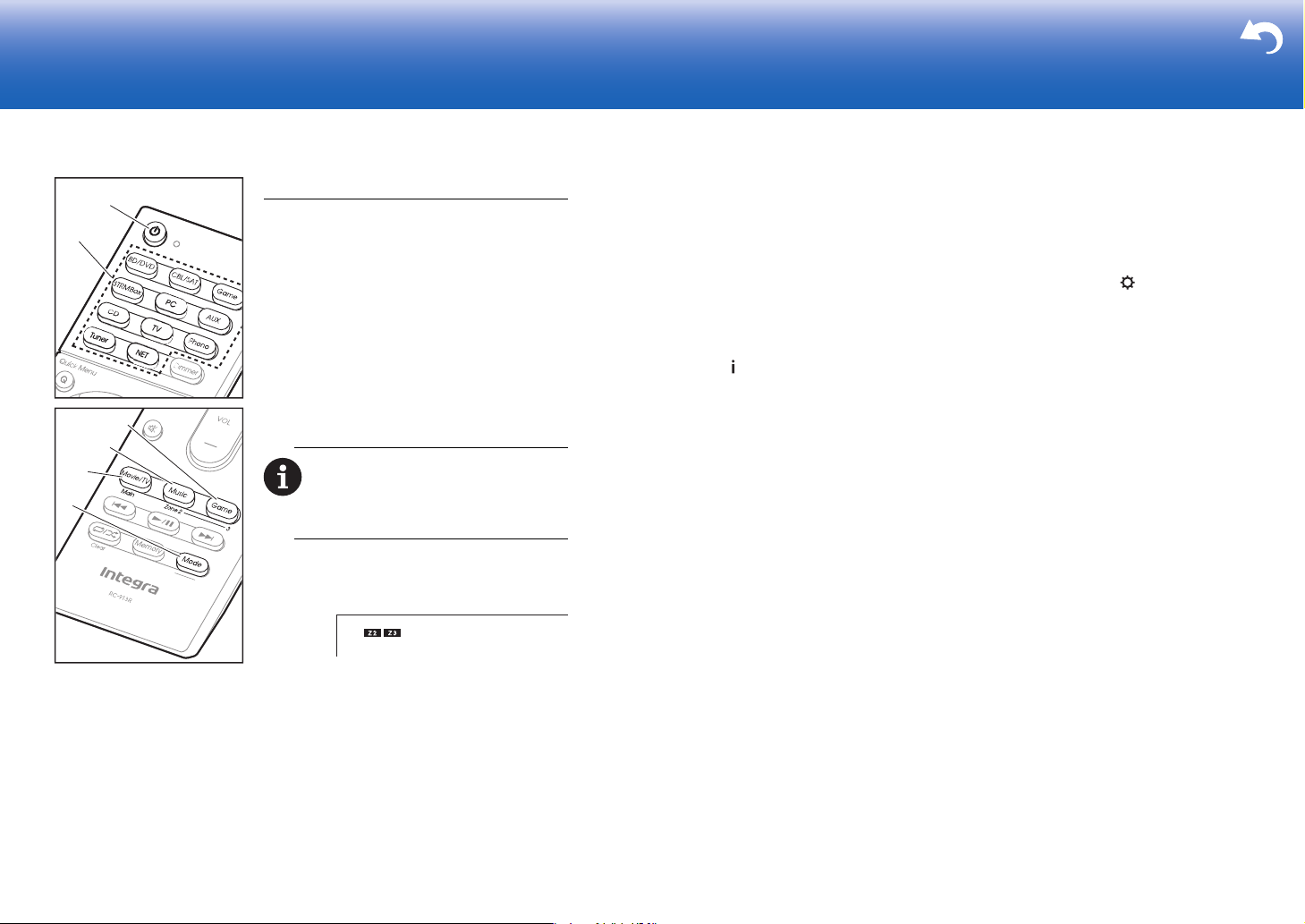
1. Press Tuner (a) on the remote controller repeatedly to
select either "AM" or "FM" on the display.
2. Press Mode (c) on the remote controller, so that the
"TunMode: Auto" is displayed on the display.
3. When you press the S / T cursor (b) buttons on the
remote controller, automatic tuning starts, and searching
stops when a station is found. When tuned into a radio
station, the "TUNED" indicator on the display lights.
You can preset up to 40 stations.
1. Tune into the AM/FM radio station you want to register.
2. Press Memory (d) on the remote controller so that the
preset number on the display flashes.
3. While the preset number is flashing (about 8 seconds),
repeatedly press the W / X cursor (b) buttons on the
remote controller to select a number between 1 and 40.
4. Press Memory (d) again on the remote controller to
register the station. When registered, the preset number
stops flashing. To select a preset radio station, press the
W / X cursor (b) buttons on the remote controller.
0 To delete a preset station, press the W / X cursor (b)
buttons on the remote controller to select the preset
number you want to delete, press Memory (d) on the
remote controller and then press Clear (e) while the
preset number is flashing. When deleted, the number on
the display goes off.
Frequency step setting
Press the button on the remote controller to select "8.
Miscellaneous" – "Tuner" – "AM/FM Frequency Step" or
"AM Frequency Step" and select the frequency step for
your area. Note that when this setting is changed, all radio
presets are deleted.
26
Page 27
> Before start > Hookup > Setup >Playback > Part Names > Advanced Manual
e
f
Troubleshooting | Appendix
Multi-zone
Play
1. Switch the remote controller to the mode for
controlling ZONE 2 or ZONE 3.
To switch to the mode for controlling ZONE 2,
while holding down Mode (a) on the remote
controller, press Zone 2 (b) for 3 or more
seconds until the remote indicator blinks
twice.
To switch to the mode for controlling ZONE 3,
while holding down Mode (a) on the remote
controller, press Zone 3 (c) for 3 or more
c
seconds until the remote indicator blinks
three times.
b
d
a
To return the remote controller to main
room control mode: While holding down
Mode (a) on the remote controller, press Main
(d) for 3 seconds or more until the remote
indicator flashes once.
2. Point the remote controller at the main unit
and press Í (e).
"Z2" or "Z3" lights on the main unit display.
3. Press the input selector button (f) of the input
to be played in the separate room. On the
main unit, after pressing Zone 2 or Zone 3,
within 8 seconds press the input selector
button to select the input to be played in the
separate room. To play the same source in
the main room and separate room, press
Zone 2 or Zone 3 on the main unit twice.
0 You cannot select different stations for the
main room and separate room with the AM/
FM radio. When you select the station for
the separate room, the main room also
switches.
0 DSD and Dolby TrueHD audio signals are
not output to ZONE 2/ZONE 3 when
selected with the "NET" input selector.
4. To adjust the volume on the power amplifier in
the separate room, adjust with VOL+/– on the
remote controller. To control on the main unit,
press Zone 2 or Zone 3 and adjust with the
Master Volume control within 8 seconds.
0 The information for a connected device can
be displayed on the TV screen in a separate
room. Press the button while the remote
controller is in the mode for controlling ZONE
2.
0 Power consumption in standby mode
increases when the multi-zone function is
being used.
To turn off the function
Press Í while in the mode for controlling ZONE
2 or ZONE 3 on the remote controller.
Playing in ZONE 2 or ZONE 3 only
If you turn the unit to standby during multi-zone
playback, the Z2 or Z3 indicator is dimmed and
the playback mode is switched to playback in a
separate room only. Setting ZONE 2/ZONE 3 to
on while this unit is in standby will also switch
the playback mode to the same setting.
WHOLE HOUSE MODE
If you press Whole House Mode while playback
is being performed in the main room, the
WHOLE HOUSE MODE is turned on, "Z2" and
"Z3" on the display light at the same time and
the playback sources of all the rooms are
switched to the same source at once.
0 The sources that can be played in ZONE 2
can be played in all rooms.
0 This function cannot be used if headphones
are connected or audio is output from the
speakers of the TV.
Settings
Settings are required in Initial Setup, "4. Multi
Zone Setup" (
feature. When checking the setting content,
refer to the following, press on the remote
controller, and check in the Setup menu that is
displayed.
– When you have connected a TV in the
separate room with an HDMI cable, have you
selected "Use" in "1. Input /Output Assign" –
"TV Out/OSD" – "Zone2 HDMI"?
– When you are playing the audio from an AV
component with an HDMI cable in the
separate
Input /Output Assign" – "TV Out/OSD" –
"Zone2 HDMI"?
– When you have connected a power amplifier
in a separate room with an analog audio
cable and you want to control the volume with
this unit, have you selected "Variable" in "7.
Multi Zone" – "Zone 2" or "Zone 3" – "Output
Level"?
ÄP23) to use the multi-zone
room
, have you selected "Use" in "1.
27
Page 28
> Before start > Hookup > Setup >Playback > Part Names > Advanced Manual
Troubleshooting | Appendix
Others
To adjust the sound quality
It is possible to enhance or moderate the bass and treble
range of all channels except the subwoofer channel. Press
Tone on the main unit several times to select the desired
setting from "Bass" and "Treble", and press the i or j
button to adjust.
0 This cannot be set if the listening mode is Direct or THX.
0 You can also adjust the sound quality of a power
amplifier connected in a separate room. After pressing
either Zone 2 or Zone 3 on the main unit, within
8 seconds press Tone and press the i or j button to
adjust.
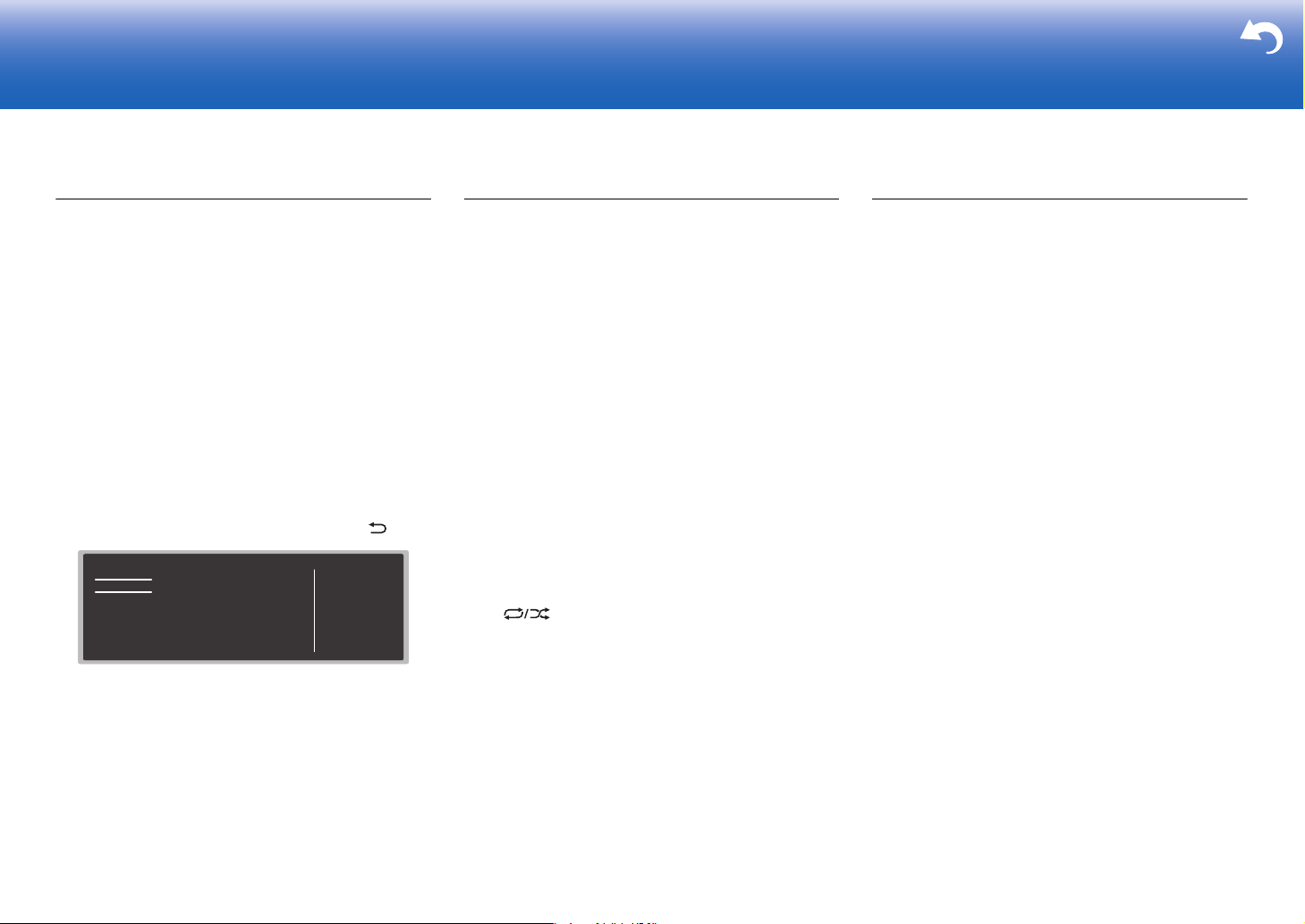
Quick Menu
By pressing Q on the remote controller during play, you can
adjust frequently used settings, such as the sound quality,
using on-screen menus. Select the item with the cursors of
the remote controller and press Enter to confirm your
selection. To return to the previous screen, press .
Quick Menu
Tone
Level
AccuEQ
Other
Bass
Treble
0 You can adjust the sound quality with "Tone". "Other"
includes settings such as "A/V Sync" that allows you to
adjust the audio delay when the video is behind the
audio, "Music Optimizer" that provides better sound
quality for compressed audio, and "HDMI Out" which
allows you to select the HDMI OUT terminal to output
from "MAIN", "SUB", and "MAIN+SUB".
BD/DVD
When the unit is operating erratically
Try restarting the unit
Restarting the unit may help it operate more smoothly. To
restart the unit, turn it to standby, and then press Í On/
Standby on the main unit for at least 5 seconds. (The unit’s
settings will be maintained.) If there is no improvement
even after the unit is restarted, try disconnecting and
reconnecting the power cords of the unit and connected
equipment.
Resetting the unit (this resets the unit settings to the
default)
If restarting the unit doesn't fix the problem, resetting the
unit to the status at the time of shipment may solve the
problem. If you reset the unit status, your preferences will
be reset to the defaults. Note them down before the
operation below.
1. While pressing the CBL/SAT input selector button on the
main unit, press Í On/Standby.
2. "Clear" appears on the display and the unit returns to
standby. Do not unplug the power cord until "Clear"
disappears from the display.
To reset the remote controller, while holding down Mode,
press until the remote indicator flash twice (about
3 seconds).
When the subwoofer produces no sound
If the setting of the front speakers is "Full Band" and during
2ch input such as from the TV or music, the low range
elements will be output from the front speakers rather than
from the subwoofer. If you would rather output from the
subwoofer, make one of the following settings.
1. Change the front speakers settings to a setting other
than "Full Band" for the crossover frequency value.
The range below the frequency you specify will be output
from the subwoofer rather than the front speakers. We
do not recommend changing this if your front speakers
have good low range reproduction capabilities.
2. Change "Double Bass" to "On".
The low range elements will be output from both the front
speakers and the subwoofer. This may mean that there
is too much bass. Do not change if this happens, or
choose option 1.
Refer to "Setup Menu" − "Crossover" in the Advanced
Manual for details.
28
Page 29
> Before start > Hookup > Setup > Playback > Part Names > Advanced Manual
12 106121315141157 9843
18 19 2116 2017
Part Names
Troubleshooting | Appendix
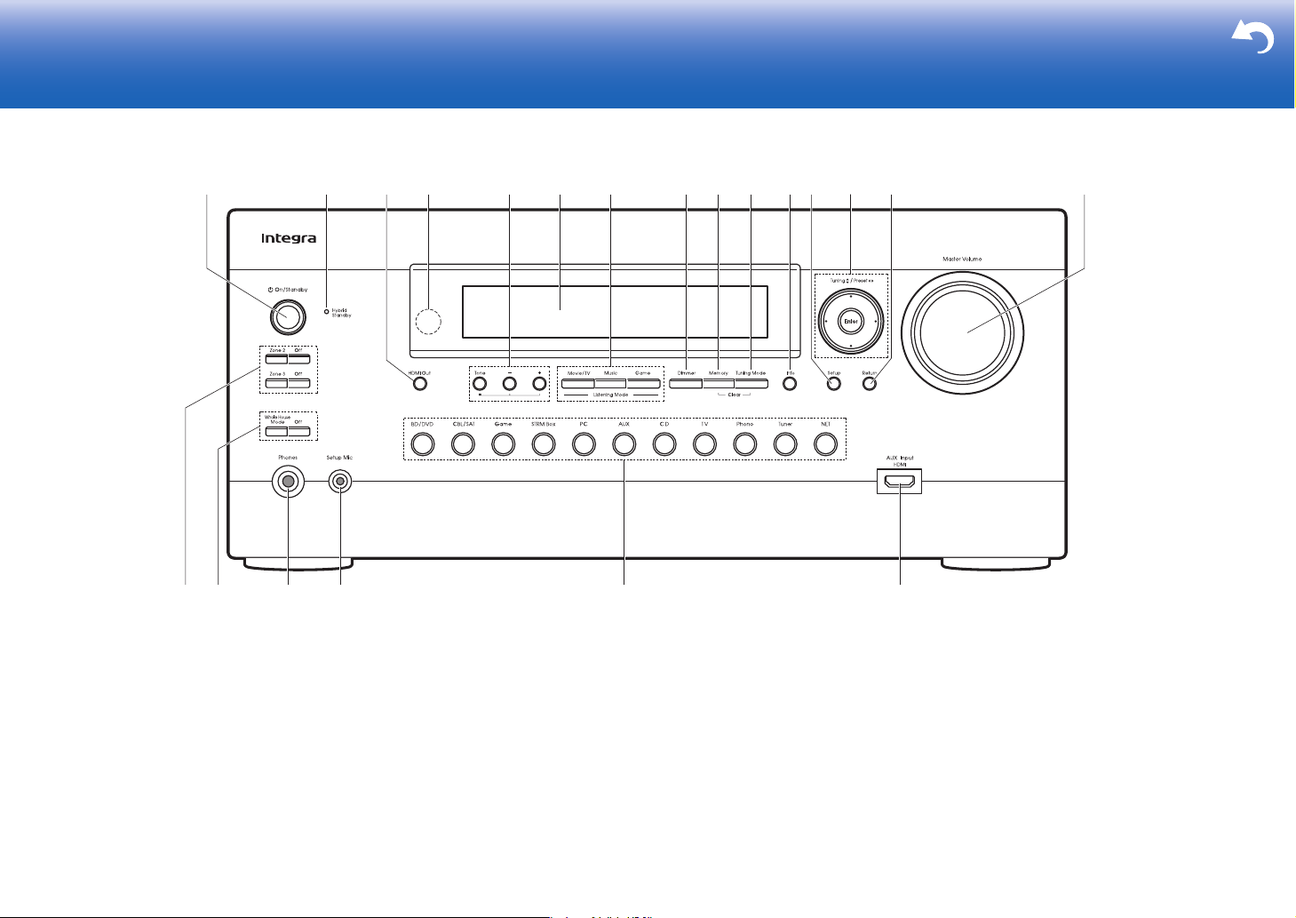
Front Panel
1. Í On/Standby button: Turns the unit on or into standby
mode.
2. Hybrid Standby indicator: Lights if the unit enters standby
mode when the features are enabled that continue to
work when this unit is in standby, such as HDMI Standby
Through and Network Standby.
3. HDMI Out button: Allows you to select the HDMI OUT
jack to output video signals from "MAIN", "SUB", and
"MAIN+SUB".
4. Remote control sensor
5. Tone, j, i buttons: Adjusts the high tone and low tone.
Press the Tone button repeatedly to select the item to
adjust from "Bass" and "Treble", and press the j or i
button to adjust.
6. Display (
ÄP31)
7. Listening Mode buttons: Select the listening mode.
(
ÄP24)
8. Dimmer button: You can adjust the brightness of the
display in three steps. It cannot be turned off completely.
9. Memory button: Used to register AM/FM radio stations.
10.
Tuning Mode button: Switches the tuning mode.
11.
Info button: Switches the information on the display.
12.
Setup button: Displays the Setup menu.
13.
Cursor buttons (Tuning43 / Preset21 button) and
Enter button: Select the item with the cursors and press
Enter to confirm your selection. When using the Tuner,
select the frequency with Tuning43, or select preset
stations with Preset21.
14.
Return button: Returns the display to the previous state.
15.
Master Volume: Allows you to adjust the volume.
16.
Zone 2/Zone 3 buttons: Controls the multi-zone function.
ÄP27)
(
Off button: Switches the multi-zone function off.
17.
Whole House Mode button: Enables the WHOLE
HOUSE MODE function to play the same source in all
the multi-zone connected rooms. (
Off button: Switches the WHOLE HOUSE MODE
function off.
18.
Phones jack: Stereo headphones with a standard plug
(1/4 inch or ø6.3 mm) are connected.
19.
Setup Mic jack: The supplied speaker setup microphone
is connected.
20.
Input selector button: Switch the input to be played.
21.
AUX Input HDMI jack: Connect to a video camera, etc.,
using a HDMI cable.
ÄP27)
29
Page 30
> Before start > Hookup > Setup > Playback > Part Names > Advanced Manual
1 4 573268
18
910 1211
13
14
17
16
15
Troubleshooting | Appendix
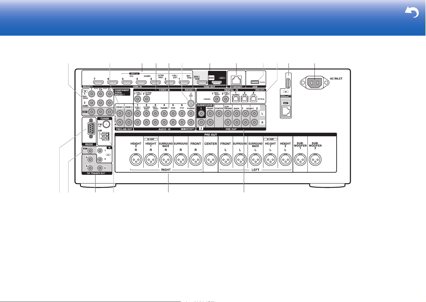
Rear Panel
1. COMPONENT VIDEO IN/OUT jacks: Transfer the video
signals of an AV component with a component video cable.
2. ZONE 2/ZONE 3 PRE/LINE OUT jacks: Output audio
signals with an analog audio cable to a pre-main
amplifier or a power amplifier in a separate room (ZONE
2/ZONE 3). (ÄP19, 20)
3. HDMI IN jacks: Transmit video signals and audio signals
with a HDMI cable connected to an AV component.
4. VIDEO IN jacks: Input the video signals from AV
components with an analog video cable.
5. AUDIO IN jacks: Input TV or AV component audio
signals with an analog audio cable.
6. GND terminal: The ground wire of the turntable is connected.
7. HDMI OUT jacks: Transmit video signals and audio
signals with a HDMI cable connected to a monitor such
30
as a TV or projector.
8. ETHERNET port: Connect to the network with an
Ethernet cable.
9. USB port: A USB storage device is connected so that music
files stored in it can be played. You can also supply power
(maximum 5V/1A) to USB devices with a USB cable.
10.
DIGITAL IN OPTICAL/COAXIAL jacks: Input the digital
audio signals from TV or AV components with a digital
optical cable or digital coaxial cable.
11.
HDBaseT™ IN/OUT jack: HDMI input signals are output via
the Ethernet cable. As they are covered with a seal when
shipped, remove it when you use the ports. Do not use the
ports to connect the ETHERNET port of network device.
12.
AC INLET: The supplied power cord is connected.
13.
RS232 port: For connection to the home control system.
14.
IR IN/OUT port: Allows you to connect a multiroom
remote control kit.
15.
12V TRIGGER OUT A/B/C jacks: Allows you to connect
a device with 12V trigger input jack to enable link
operation between the device and the unit.
16.
TUNER AM/FM 75Ω terminal: The supplied antennas
are connected.
17.
PRE OUT (XLR) jacks: Use a balanced XLR cable to
connect the power amplifier or powered subwoofer. Up to
two powered subwoofers can be connected.
18.
PRE OUT (RCA) jacks: Use an analog audio cable or
subwoofer cable to connect the power amplifier or
powered subwoofer. Up to two powered subwoofers can
be connected.
Page 31
> Before start > Hookup > Setup > Playback > Part Names > Advanced Manual
8
9
1
2
3
5
7
6
4
12
11
10
14
13
15
Approx.5 m (16 ft.)
14
6
2 35
77
Troubleshooting | Appendix
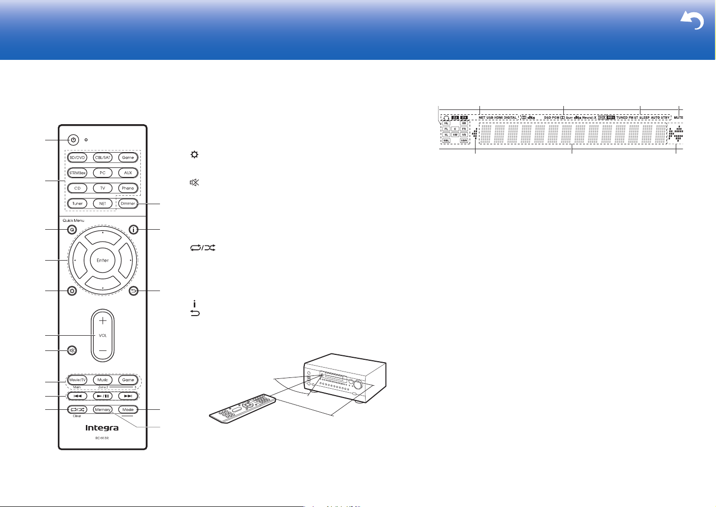
Remote Controller
1. Í button: Turns the unit on or into standby mode.
2. Input selector buttons: Switches the input to be played.
3. Q (Quick Menu) button: You can perform common settings on the
TV screen. (
4. Cursor buttons and Enter button: Select the item with the cursors
and press Enter to confirm your selection.
5. button: Displays the Setup menu.
6. Volume buttons: Allows you to adjust the volume. This button
also cancels the muting.
7. button: Temporarily mutes audio. Press again to cancel
muting.
8. Listening Mode buttons: Allows you to select the listening mode.
ÄP24)
(
Main/Zone 2/Zone 3 buttons: Controls the multi-zone function.
ÄP27)
(
9. Play buttons: You can start play of the Music Server or USB.
10.
playing Music Server or USB.
Clear button: Deletes all characters you have entered when
entering text on the TV screen.
11.
Dimmer button: You can adjust the brightness of the display in
three steps. It cannot be turned off completely.
12.
button: Switches the information on the display.
13.
button: Returns the display to the previous state.
14.
Mode button: Switches tuning to an AM/FM station between
automatic tuning and manual tuning.
15.
Memory button: Used to register AM/FM radio stations.
ÄP28)
button: Used for repeat or random play operations when
30°
30°
Display
1. Speaker/Channel display: Displays the output channel that
corresponds to the selected listening mode.
2. Lights in the following conditions.
Ë: When headphones are connected.
Z2/Z3: When ZONE 2/ZONE 3 is on.
NET: When "NET" is selected with the input selector and the unit is
connected to the network. It will flash if the connection to the network
is not correct.
USB: When "NET" is selected with the input selector and the unit is
connected by USB and the USB device is selected. Flashes if the
USB is not properly connected.
HDMI: When HDMI signals are input and the HDMI input is selected.
DIGITAL: When digital signals are input and the digital input is selected.
3. Lights according to the type of input digital audio signals and the
listening mode.
4. Lights in the following conditions.
RDS (Australian models): Receiving RDS broadcasting.
TUNED: Receiving AM/FM radio.
FM ST: Receiving FM stereo.
SLEEP: When the sleep timer is set.
AUTO STBY: When Auto Standby function is enabled.
5. Flashes when muting is on.
6. Displays various information of the input signals. Characters that
cannot be displayed on this unit are replaced with asterisks ( * ).
0
When playing back software which has been encoded in Dolby Digital,
Dolby Digital Plus, Dolby TrueHD and Dolby Atmos, sometimes you may
see a brief message which will read "DialogNorm: X dB" (X being a
numeric value). For example, if you see the following message:
"DialogNorm:+4dB", to keep the overall output level at THX calibrated
loudness, just turn down the volume control by 4dB.
7. Lights when operating the "NET" input selector indicating remote controller
cursor operations are possible in screens showing list of tracks, for example.
31
Page 32

License and Trademark Information
®
Manufactured under license from Dolby Laboratories. Dolby, Dolby Atmos,
Dolby Surround, and the double-D symbol are trademarks of Dolby
Laboratories.
For DTS patents, see http://patents.dts.com. Manufactured under license from
DTS, Inc. DTS, the Symbol, DTS in combination with the Symbol, DTS:X, and
the DTS:X logo are registered trademarks or trademarks of DTS, Inc. in the
United States and/or other countries. © DTS, Inc. All Rights Reserved.
THX and the THX logo are trademarks of THX Ltd., registered in the U.S. and
other countries. U.S. Pat. nos. 7,254,239 & 7,593,533 & 7,974,425 & 8,452, 028
& 8,509,457 Taiwan Pat. I238671 European Pat. 1,360,874
THX Ultra2 Plus
Before any home theater component can be THX Ultra2 Plus certified, it must
pass a rigorous series of quality and performance tests. Only then can a
product feature the THX Ultra2 Plus logo, which is your guarantee that the
Home Theater products you purchase will give you superb performance for
many years to come. THX Ultra2 Plus requirements define hundreds of
parameters, including power amplifier performance, and integrated amplifier
performance and operation for both digital and an alog domains. THX Ultra2
Plus receivers also feature proprietary THX technologies (e.g., THX Mode)
which accurately translate movie soundtracks for home theater playback.
Re-Equalization and the “Re-EQ” logo are trademarks of THX Ltd.
“VLSC” and “VLSC (logo)” are trademarks of Onkyo Corporation.
The terms HDMI and HDMI High-Definition Multimedia Interface, and the HDMI
Logo are trademarks or registered trademarks of HDMI Licensing LLC in the
United States and other countries.
AirPlay, iPad, iPhone, and iPod touch are trademarks of Apple Inc., registered
in the U.S. and other countries.
iPad Air and iPad mini are trademarks of Apple Inc.
“Made for iPod”, “Made for iPhone” and “Made for iPad” mean that an electronic
accessory has been designed to connect specifically to iPod, iPhone, or iPad,
respectively, and has been certified by the developer to meet Apple
32
performance standards. Apple is not responsible for the operation of this d evic e
or its compliance with safety and regulatory standards.
Please note that the u se of this accessory with iPod, iPhone or iPad may affect
wireless performance.
AirPlay works with iPhone, iPad, and iPod touch with iOS 4.3.3 or later, Mac
with OS X Mountain Lion or later, and PC with iTunes 10.2.2 or later.
Apple, Apple TV and Safari ar e trademarks of Apple Inc., registered in the U.S.
and other countries.
HDBaseTTM and the HDBaseT Alliance logo are trademarks of the HDBaseT
Alliance.
PANDORA, the PANDORA logo, and the Pandora trade dress are trademarks
or registered trademarks of Pandora Media, Inc. Used with permission.
This Mark Certifies that this product is compliant with the BLACKFIRE
ALLIANCE Standard.
Please refer to WWW.BLACKFIREALLIANCE.COM for more information.
BLACKFIRETM is a Registered Trademark (No. 85,900,599) of BLACKFIRE
RESEARCH CORP. All rights reserved.
FireConnectTM is technology powered by BlackFire Research.
The product with this logo is conformed to Hi-Res Audio standard defined by
Japan Audio Society. This logo is used under license from Japan Audio So ciety.
This product is protected by certain intellectual property rights of Microsoft. Use
or distribution of such technology outside of this product is prohibited without a
license from Microsoft.
Windows and the Windows logo are trademarks of the Microsoft group of companies.
QR Code is a registered trademark of DENSO WAVE INCORPORATED.
“x.v.Color” and “x.v.Color” logo are trademarks of Sony Corporation.
DSD and the Direct Stream Digital logo are trademarks of Sony Corporation.
MPEG Layer-3 audio coding technology licensed from Fraunhofer IIS and
Thomson.
AccuEQ, Music Optimizer, RIHD and WRAT are trademarks of Onkyo
Corporation.
“All other trademarks are the property of their respective owners.”
DISCLAIMER
Through this device you are able to link to other services or websites which are
not under the control of any company which has designed, manufactured or
distributed/have distributed this device, and its affiliates (collectively,
“Company”). We have no control over the nature, content and availability of
those services. The inclusion of any links does not necessarily imply a
recommendation or endorse the views expressed within them.
All information, content and services available through this device belong to
third parties and are protected by copyright, patent, trademark and/or other
intellectual property laws of applicable countries.
The information, content and services provided through this device are for your
personal, noncommercial use only. Any information, content or services may
not be used in any manner other than previously approved by the appropriate
content owner or service provider.
You may not modify, copy, republish, translate, exploit, create derivative works,
upload, post, transmit, sell or distribute in any manner any information, content
or services available through this device, unless expressly permitted by the
appropriate copyright, patent, trademark and/or other intellectual property
owner, including, without limitation, content owner or service provider.
THE CONTENT AND SERVICES AVAILABLE THROUGH THIS DEVICE ARE
PROVIDED “AS IS”.
COMPANY DOES NOT WARRANT INFORMATION, CONTENT OR
SERVICES SO PROVIDED, EITHER EXPRESSLY OR IMPLIEDLY, FOR ANY
PURPOSE.
COMPANY EXPRESSLY DISCLAIMS ANY WARRANTIES, EXPRESS OR
IMPLIED, INCLUDING BUT NOT LIMITED TO, WARRANTIES OF TITLE,
NON-INFRINGEMENT, MERCHANTABILITY OR FITNESS FOR A
PARTICULAR PURPOSE.
Company makes no representation or warranty of any kind, express or implied,
about the completeness, accuracy, validity, legality, reliability, suitability or
availability with respect to the information, content or services available through
this device. Company shall not be liable, whether in contract or tort, including
negligence and strict liability, for any direct, indirect, special, incidental or
consequential damages or any other damages arising out of, or in connection
with, any information contained in, or as a result of the use of any content or
service by you or any third party, even if Company has been advised of the
possibility of such damages, nor shall Company be liable for any third party
claims against users of this device or any third party.
In no event shall Company be responsible nor liable for, without limiting the
generality of the foregoing, any interruption or suspension of any information,
content or service available through this device. Company is neither
responsible nor liable for customer service related to the information, content
and services available through this device. Any question or request for service
relating to the information, content or services should be made directly to the
appropriate content owners and services providers.
Page 33

333435
Page 34

Page 35

Page 36

F1703-1
<U.S.A.>
18 Park Way, Upper Saddle River, N.J. 07458, U.S.A.
Tel: 800-225-1946, 201-818-9200 Fax: 201-785-2650
http://www.integrahometheater.com
<Germany>
Gutenbergstrasse 3, 82178 Puchheim, Germany
Tel: +49-8142-4401-0 Fax: +49-8142-4208-213
http://www.integra.eu
<PRC>
302, Building 1, 20 North Chaling Rd., Xuhui District, Shanghai, China 200032,
Tel: +86-21-52131366 Fax: +86-21-52130396
http://www.integra.com.cn
2-3-12 Yaesu, Chuo-ku, Tokyo 104-0028 JAPAN
http://www.integraworldwide.com
(C) Copyright 2016 Onkyo & Pioneer Corporation Japan. All rights reserved.
http://www.onkyo.com/privacy/
SN 29402434A
*29402434A*
Page 37

> Specifications > Settings > Listening Modes > Playback Function > Basic Manual
Troubleshooting | Appendix
AV Controller
DRC-R1
Specifications
Main features ........................................................................... 2
General Specifications............................................................. 3
About HDMI ............................................................................. 5
Settings
Setup Menu ............................................................................. 6
Initial Setup ............................................................................ 36
Quick Menu ........................................................................... 38
Advanced Manual
Control Function Settings ...................................................... 40
Firmware Update ................................................................... 41
Listening Modes
Selecting Listening Modes..................................................... 44
Listening Mode Effects .......................................................... 45
Selectable Listening Modes................................................... 49
Playback Function
AM/FM Radio......................................................................... 63
USB Storage Device.............................................................. 65
Internet Radio ........................................................................ 67
Spotify.................................................................................... 69
Music Server.......................................................................... 70
Other Functions .................................................................... 73
Supplementary information for player functions ................... 74
Troubleshooting .................................................................. 75
Appendix .............................................................................. 81
The Basic Manual includes information needed when starting up and
also instructions for frequently used operations. The Advanced Manual
has more detailed information and advanced settings.
Page 38

> Specifications > Settings > Listening Modes > Playback Function > Basic Manual
Troubleshooting | Appendix
main room and listen in a separate room (ZONE 2/
ZONE 3)
•
Main features
•
Conforms to the THX Ultra2 Plus specification: THX is a
series of specifications for the accurate reproduction of
movies propounded by the film director George Lucas.
This unit is equipped with a variety of THX technology
to faithfully reproduce according to the sound design
envisaged by the movie producer, including surround
modes that take account of factors such as the size
and number of speakers, and the differences in
environments between home theaters and movie
theaters.
•
Supports playback in Dolby Atmos format and has
Dolby Surround listening mode
•
Supports playback in DTS:X format and has DTS
Neural:X listening mode
•
The HDMI jack supports 4K video input and output.
Jacks IN1 to 5 and OUT MAIN/SUB support HDCP2.2
•
HDMI CEC functionality: Control features such as
linking input switching with the input selector and
players conforming to the CEC standard, switching
audio output and volume using the remote controller of
a CEC-compliant TV, and automatically switching this
unit to standby when the TV is turned off
•
HDMI Standby Through: Video and audio signals from
AV components can be transmitted to the TV even if this
unit is in standby
•
ARC: Connection with an ARC-compatible TV is
complete with one HDMI cable
•
Easy Initial Setup using onscreen guidance and OnScreen Display (OSD) showing operations on the TV
•
Internet radio and AirPlay via wired LAN and network
features such as Music Server that enables PC music
file playback, USB playback, plus other playback
features such as AM/FM radio play
•
Playback formats supported by Music Server and USB
include WAV, FLAC and DSD high-res source
•
Multi-zone Connection which allows you to play in the
2
Equipped with RS232 port, IR IN/OUT jack, and 12V
TRIGGER OUT jack
•
XLR balanced jack (11.2 channel output) minimizing
noises in long distance transmission
Page 39

> Specifications > Settings > Listening Modes > Playback Function > Basic Manual
Troubleshooting | Appendix
General Specifications
■ Amplifier Section
Input Sensitivity and Impedance (1 kHz, 100 W/8 Ω)
200 mV/82 kΩ (LINE (Unbalance))
3.5 mV/47 kΩ (PHONO MM)
Rated RCA Output Level and Impedance
1 V/330 Ω (PRE OUT)
1 V/330 Ω (SUBWOOFER PRE OUT)
200 mV/1.2 kΩ (ZONE LINE OUT)
2 V/1.2 kΩ (ZONE PRE OUT)
Rated XLR Output Level and Impedance
2 V/220 Ω (PRE OUT L/R)
Phono Overload
70 mV (MM 1 kHz 0.5%)
Frequency Response
5 Hz - 100 kHz/+1 dB, –3 dB (Direct)
Tone Control Characteristics
±10 dB, 100 Hz (BASS)
±10 dB, 10 kHz (TREBLE)
Signal to Noise Ratio
110 dB (IHF-A, LINE IN, SP OUT)
80 dB (IHF-A, PHONO IN, SP OUT)
Headphone Output Impedance
43 Ω
Headphone Rated Output
57 mW (32 Ω, 1 kHz, 10% THD)
■ Video Section
Signal level
1 Vp-p/75 Ω (Composite Video)
1 Vp-p/75 Ω (Component Video Y)
0.7 Vp-p/75 Ω (Component Video PB/PR)
Maximum resolution supported by component video
1080i (*)
*
* When output from HDMI, only 480i/576i resolution
input is possible.
■ Tuner Section
FM Tuning Frequency Range
87.5 MHz - 107.9 MHz (North American)
87.5 MHz - 108.0 MHz, RDS (Others)
AM Tuning Frequency Range
530 kHz - 1710 kHz (North American)
522/530 kHz - 1611/1710 kHz (Others)
Preset Channel
40
■ Network Section
Ethernet LAN
10BASE-T/100BASE-TX
■ General
Power Supply
AC 120 V, 60 Hz (North American)
AC 220 - 230 V, 50/60 Hz (Others)
Power Consumption
65 W
0.15 W (Stand-by, North American)
0.2 W (Stand-by, Others)
50 W (No-sound)
8.5 W (HDMI Standby Through)
2.5 W (Network Standby)
Dimensions (W × H × D)
435 mm × 197 mm × 436 mm
17-1/8" × 7-3/4" × 17-3/16"
Weight
13.1 kg (28.9 lbs.)
■ HDMI
Input
IN1 (BD/DVD, HDCP2.2), IN2 (CBL/SAT, HDCP2.2),
IN3 (STRM BOX, HDCP2.2), IN4 (GAME, HDCP2.2),
IN5 (PC, HDCP2.2), IN6, IN7, AUX INPUT HDMI
(front)
Output
OUT MAIN (ARC, HDCP2.2) 55 mA
OUT SUB (HDCP2.2) 55 mA
Supported
Deep Color, x.v.Color™, LipSync, Audio Return
Channel, 3D, 4K 60 Hz, CEC, Extended Colorimetry
(sYCC601, Adobe RGB, Adobe YCC601), Content
Type, HDR
Audio Format
Dolby Atmos, Dolby TrueHD, Dolby Digital, Dolby
Digital Plus, DTS, DTS:X, DTS-HD Master Audio,
DTS-HD High Resolution Audio, DTS 96/24, DTSES, DTS-HD Express, DSD, PCM
Maximum Video Resolution
4k 60 Hz (YCbCr 4:4:4)
Compatible input resolutions
HDMI input : 4K, 1080p/24, 1080p, 1080i, 720p,
480p/576p
Component input : 480i/576i
Composite input : 480i/576i
•
The output from the HDMI OUT jack to the TV is the
same resolution as the input. When using a TV that
supports 4K, 1080p HDMI video signals can also be
output as 4K.
■ HDBaseT
OUT (*)/IN (HDMI)
* 3G bps or less for 4K (use a CAT 5e or better cable,
70 m or less in length)
■ Video Inputs
Component
IN1 (BD/DVD), IN2 (GAME)
Composite
IN1 (CBL/SAT), IN2 (STRM BOX)
■ Video Outputs
Component
OUT
■ Audio Inputs
3
Page 40

> Specifications > Settings > Listening Modes > Playback Function > Basic Manual
Troubleshooting | Appendix
Digital
OPTICAL 1 (GAME), 2 (CD), 3 (TV)
COAXIAL 1 (BD/DVD), 2 (CBL/SAT)
Analog
CBL/SAT, STRM BOX, BD/DVD, GAME, CD, TV,
PHONO
■ Audio Outputs
Analog
ZONE2 PRE/LINE OUT
ZONE3 PRE/LINE OUT
PRE OUT (FRONT L/R, CENTER, SURROUND L/R,
SURROUND BACK L/R, HEIGHT 1 L/R, HEIGHT 2
L/R, 2 SUBWOOFER)
Balance
PRE OUT (FRONT L/R, CENTER, SURROUND L/R,
SURROUND BACK L/R, HEIGHT 1 L/R, HEIGHT 2
L/R, 2 SUBWOOFER)
Phones
PHONES (Front, ø 6.3 mm, 1/4")
■ Others
Setup Mic : 1 (Front)
USB : 1 (Ver. 2.0, 5 V/1 A)
Ethernet : 1
RS232 : 1
12V TRIGGER OUT : 3 (A: 100 mA, B: 25 mA, C: 25 mA)
IR IN : 2 (1/2)
IR OUT : 1
notice.
■ Power consumption in standby mode
•
In the following cases, the power consumption in
standby mode may reach up to a maximum of 8.5 W:
–
When "Network Standby" is set to "On"
–
When "HDMI CEC" is set to "On"
–
When "HDMI Standby Through" is set to other than
"Off"
Specifications and features are subject to change without
4
Page 41

> Specifications > Settings > Listening Modes > Playback Function > Basic Manual
Troubleshooting | Appendix
About HDMI
■ Compatible functions
HDMI (High Definition Multimedia Interface) is a digital
interface standard for connecting TVs, projectors, Bluray Disc/DVD players, set-top boxes, and other video
components. Until now, several separate video and audio
cables have been required to connect AV components.
With HDMI, a single cable can carry control signals, digital
video and digital audio (2 ch PCM, multichannel digital
audio, and multichannel PCM).
HDMI CEC functionality:
By connecting devices and HDMI cables that comply with
the CEC (Consumer Electronics Control) specification of
the HDMI standard, a variety of linked operation become
possible between devices. You can enjoy features such as
linking input switching with the input selector and players,
control volume using the remote controller of the TV, and
automatically switching this unit to standby when the TV is
turned off.
The unit is designed to link with products that comply with
the CEC standard, and that linked operation is not always
guaranteed with all CEC devices. For linked functions
to work properly, do not connect more CEC-compliant
components than the quantities specified below, to the
HDMI jack.
•
Blu-ray Disc/DVD players: up to 3 units.
•
Blu-ray Disc/DVD recorders: up to 3 units.
•
Cable TV tuner, terrestrial digital tuner, and satellite
broadcasting tuner: up to 4 units.
Operation has been confirmed on the following devices:
(As of February 2016)
Toshiba brand televisions; Sharp brand televisions; Onkyo
and Integra brand RIHD-compatible players; Toshiba brand
players and recorders; Sharp brand players and recorders
(when used with a Sharp brand television)
ARC(Audio Return Channel):
By connection a TV that supports ARC with a single HDMI
cable, you can not only output the audio and video from
this unit to the TV, but also input the audio from the TV to
this unit.
HDMI Standby Through:
Even if this unit is in standby, the input signals from AV
components are transmitted to the TV.
Deep Color:
By connecting devices supporting Deep Color, video
signals input from the devices can be reproduced on the
TV with even more colors.
x.v.Color™:
This technology realizes even more realistic colors by
broadening the color gamut.
3D:
You can transmit 3D video signals from AV components to
the TV.
4K:
This unit supports 4K (3840×2160p) and 4K SMPTE
(4096×2160p) video signals.
LipSync:
This setting automatically corrects any desynchronization
between the video and audio signals based on data from
the HDMI LipSync compatible TV.
Copyright Protection:
The unit supports Revision 1.4 and Revision 2.2 (HDMI
OUT MAIN/SUB and HDMI IN1 to 5 only) of the HDCP
(High-bandwidth Digital Content Protection), a copyprotection system for digital video signals. Other devices
connected to the unit must also support HDCP.
■ Supported Audio Formats
2 ch linear PCM:
32 kHz, 44.1 kHz, 48 kHz, 88.2 kHz, 96 kHz, 176.4 kHz,
192 kHz, 16/20/24 bit
Multi-channel linear PCM:
Maximum 7.1 channels, 32 kHz, 44.1 kHz, 48 kHz,
88.2 kHz, 96 kHz, 176.4 kHz, 192 kHz, 16/20/24 bit
Bitstream:
Dolby Atmos, Dolby Digital, Dolby Digital Plus, Dolby
TrueHD, DTS, DTS:X, DTS-HD High Resolution Audio,
DTS-HD Master Audio
DSD:
Supported sampling rates: 2.8 MHz
Your Blu-ray Disc/DVD player must also support HDMI
output of the above audio formats.
■ Supported resolutions
HDMI IN1 to IN5:
•
Copyright protection technology: HDCP1.4/HDCP2.2
•
Color space (Color Depth):
–
720×480i 60Hz, 720×576i 50Hz, 720×480p
60Hz, 720×576p 50Hz, 1920×1080i 50/60Hz,
1280×720p 24/25/30/50/60Hz, 1680×720p
24/25/30/50/60Hz, 1920×1080p 24/25/30/50/60Hz,
2560×1080p 24/25/30/50/60Hz, 4K (3840×2160p)
24/25/30Hz, 4K SMPTE (4096×2160p) 24/25/30Hz :
RGB/YCbCr4:4:4 (8/10/12 bit), YCbCr4:2:2 (12 bit)
–
4K (3840×2160p) 50/60Hz, 4K SMPTE (4096
×2160p) 50/60Hz : RGB/YCbCr4:4:4 (8 bit),
YCbCr4:2:2 (12 bit), YCbCr4:2:0 (8/10/12 bit)
HDMI IN6 to IN7, Front:
•
Copyright protection technology: HDCP1.4
•
Color space (Color Depth):
–
720×480i 60Hz, 720×576i 50Hz, 720×480p
60Hz, 720×576p 50Hz, 1920×1080i 50/60Hz,
1280×720p 24/25/30/50/60Hz, 1680×720p
24/25/30/50/60Hz, 1920×1080p 24/25/30/50/60Hz,
2560×1080p 24/25/30/50/60Hz : RGB/YCbCr4:4:4
(8/10/12 bit), YCbCr4:2:2 (12 bit)
–
4K (3840×2160p) 24/25/30Hz, 4K SMPTE (4096
×2160p) 24/25/30Hz : RGB/YCbCr4:4:4 (8 bit),
YCbCr4:2:2 (12 bit)
–
4K (3840×2160p) 50/60Hz, 4K SMPTE (4096×
2160p) 50/60Hz : YCbCr4:2:0 (8 bit)
5
Page 42

> Specifications > Settings > Listening Modes > Playback Function > Basic Manual
Troubleshooting | Appendix
1. Input/Output Assign
Setup Menu
The unit allows you to configure advanced settings to provide you with an even better
experience.
Operation:
Use the on-screen displays (OSD) that appear on the TV to make the settings.
Press
Select the item with the cursor / buttons of the remote controller and press Enter to
confirm your selection.
Use the cursors / to change the default values.
6
on the remote controller to display the Setup menu.
Setup
1. Input/Output Assign
2. Speaker
3. Audio Adjust
4. Source
5.
Listening Mode Preset
6. Hardware
7. Multi Zone
8. Miscellaneous
•
To return to the previous screen, press .
•
To exit the settings, press .
1. TV Out / OSD
2. HDMI Input
3. Video Input
4. Digital Audio Input
5. Analog Audio Input
Make settings related to output to the TV, change the settings for jack allocations to the
various input selectors, and set the feature for displaying operations on the TV (OSD), etc.
■ 1. TV Out / OSD
Setting Item Default Value Setting Details
HDMI Out MAIN Select the HDMI jack to be connected with the TV.
"MAIN": When connecting the TV to the HDMI OUT
MAIN jack
"SUB": When connecting the TV to the HDMI OUT
SUB jack
"MAIN+SUB": When connecting to both the MAIN
and SUB jacks
1080p -> 4K
Upscaling
Super Resolution 2 When you have set "1080p -> 4K Upscaling" to
Zone 2 HDMI Not Use Make the setting when you output to the Zone 2 TV
HDBaseT(TM) Not Use Set when outputting the input HDMI signals from
OSD Language English Select the on-screen display language from the
Off When using a TV that supports 4K, video signals
input at 1080p can be automatically upscaled to 4K
for output.
"Off": Do not use this function
"Auto": Use this function
•
Select "Off" if your TV does not support 4K.
"Auto", you can select the degree of video signal
correction from "Off" and between "1" (weak) and
"3" (strong).
connected to the HDMI OUT ZONE 2/SUB jack.
"Use": Enable this function
"Not Use": Disable this function
the HDBaseT port via an Ethernet cable.
"MAIN": When connecting the HDMI OUT MAIN
jack and the HDBaseT IN port
"SUB/ZONE 2": When connecting the HDMI OUT
SUB/ZONE 2 jack and the HDBaseT IN port
following.
English, German, French, Spanish, Italian, Dutch,
Swedish, Russian, Chinese
Page 43
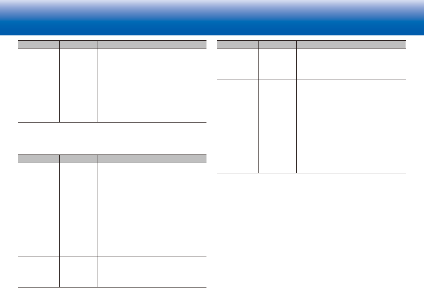
> Specifications > Settings > Listening Modes > Playback Function > Basic Manual
Troubleshooting | Appendix
Setting Item Default Value Setting Details
Impose OSD On Set whether or not to display the information on
the TV when the volume is adjusted or input is
changed, for example.
"On": OSD displayed on the TV
"Off": OSD not displayed on the TV
•
OSD may not be displayed depending on the
input signal even if "On" is selected. If the
operation screen is not displayed, change the
resolution of the connected device.
Screen Saver 3 minutes Set the time to start the screen saver.
Select a value from "3 minutes", "5 minutes", "10
minutes" and "Off".
■ 2. HDMI Input
You can change input assignment between the input selectors and HDMI IN jacks.
Setting Item Default Value Setting Details
BD/DVD HDMI 1
(HDCP 2.2)
CBL/SAT HDMI 2
(HDCP 2.2)
GAME HDMI 4
(HDCP 2.2)
STRM BOX HDMI 3
(HDCP 2.2)
"HDMI 1 (HDCP 2.2)" to "HDMI 7": Assign a
desired HDMI IN jack to the BD/DVD button. If you
do not assign a jack, select "-----". To select an
HDMI IN jack already assigned to another input
selector, change its setting to "-----" first.
"HDMI 1 (HDCP 2.2)" to "HDMI 7": Assign a
desired HDMI IN jack to the CBL/SAT button. If
you do not assign a jack, select "-----". To select
an HDMI IN jack already assigned to another input
selector, change its setting to "-----" first.
"HDMI 1 (HDCP 2.2)" to "HDMI 7": Assign a
desired HDMI IN jack to the Game button. If you do
not assign a jack, select "-----". To select an HDMI
IN jack already assigned to another input selector,
change its setting to "-----" first.
"HDMI 1 (HDCP 2.2)" to "HDMI 7": Assign a
desired HDMI IN jack to the STRM Box button. If
you do not assign a jack, select "-----". To select
an HDMI IN jack already assigned to another input
selector, change its setting to "-----" first.
Setting Item Default Value Setting Details
PC HDMI 5
(HDCP 2.2)
CD ----- "HDMI 1 (HDCP 2.2)" to "HDMI 7": Assign a
TV ----- "HDMI 1 (HDCP 2.2)" to "HDMI 7": Assign a
PHONO ----- "HDMI 1 (HDCP 2.2)" to "HDMI 7": Assign a
"HDMI 1 (HDCP 2.2)" to "HDMI 7": Assign a
desired HDMI IN jack to the PC button. If you do
not assign a jack, select "-----". To select an HDMI
IN jack already assigned to another input selector,
change its setting to "-----" first.
desired HDMI IN jack to the CD button. If you do
not assign a jack, select "-----". To select an HDMI
IN jack already assigned to another input selector,
change its setting to "-----" first.
desired HDMI IN jack to the TV button. If you do
not assign a jack, select "-----". To select an HDMI
IN jack already assigned to another input selector,
change its setting to "-----" first.
desired HDMI IN jack to the Phono button. If you
do not assign a jack, select "-----". To select an
HDMI IN jack already assigned to another input
selector, change its setting to "-----" first.
7
Page 44

> Specifications > Settings > Listening Modes > Playback Function > Basic Manual
Troubleshooting | Appendix
■ 3. Video Input
You can change input assignment between the input selectors and COMPONENT VIDEO
IN jacks and the VIDEO IN jacks. If you do not assign a jack, select "-----".
Setting Item Default Value Setting Details
BD/DVD COMPONENT 1 "COMPONENT 1", "COMPONENT 2": Assign the
COMPONENT VIDEO IN jacks to the BD/DVD
button.
"VIDEO 1", "VIDEO 2": Assign a desired VIDEO IN
jack to the BD/DVD button.
CBL/SAT VIDEO 1 "COMPONENT 1", "COMPONENT 2": Assign the
COMPONENT VIDEO IN jacks to the CBL/SAT
button.
"VIDEO 1", "VIDEO 2": Assign a desired VIDEO IN
jack to the CBL/SAT button.
GAME COMPONENT 2 "COMPONENT 1", "COMPONENT 2": Assign
the COMPONENT VIDEO IN jacks to the Game
button.
"VIDEO 1", "VIDEO 2": Assign a desired VIDEO IN
jack to the Game button.
STRM BOX VIDEO 2 "COMPONENT 1", "COMPONENT 2": Assign the
COMPONENT VIDEO IN jacks to the STRM Box
button.
"VIDEO 1", "VIDEO 2": Assign a desired VIDEO IN
jack to the STRM Box button.
PC ----- "COMPONENT 1", "COMPONENT 2": Assign the
COMPONENT VIDEO IN jacks to the PC button.
"VIDEO 1" to "VIDEO 2": Assign a desired VIDEO
IN jack to the PC button.
CD ----- "COMPONENT 1", "COMPONENT 2": Assign the
COMPONENT VIDEO IN jacks to the CD button.
"VIDEO 1", "VIDEO 2": Assign a desired VIDEO IN
jack to the CD button.
TV ----- "COMPONENT 1", "COMPONENT 2": Assign the
COMPONENT VIDEO IN jacks to the TV button.
"VIDEO 1", "VIDEO 2": Assign a desired VIDEO IN
jack to the TV button.
Setting Item Default Value Setting Details
PHONO ----- "COMPONENT 1", "COMPONENT 2": Assign
the COMPONENT VIDEO IN jacks to the Phono
button.
"VIDEO 1", "VIDEO 2": Assign a desired VIDEO IN
jack to the Phono button.
8
Page 45

> Specifications > Settings > Listening Modes > Playback Function > Basic Manual
Troubleshooting | Appendix
■ 4. Digital Audio Input
You can change input assignment between the input selectors and DIGITAL IN COAXIAL/
OPTICAL jacks. If you do not assign a jack, select "-----".
Setting Item Default Value Setting Details
BD/DVD COAXIAL 1 "COAXIAL 1", "COAXIAL 2", "OPTICAL 1",
"OPTICAL 2", "OPTICAL 3": Assign a desired
DIGITAL IN jack to the BD/DVD button.
CBL/SAT COAXIAL 2 "COAXIAL 1", "COAXIAL 2", "OPTICAL 1",
"OPTICAL 2", "OPTICAL 3": Assign a desired
DIGITAL IN jack to the CBL/SAT button.
GAME OPTICAL 1 "COAXIAL 1", "COAXIAL 2", "OPTICAL 1",
"OPTICAL 2", "OPTICAL 3": Assign a desired
DIGITAL IN jack to the Game button.
STRM BOX ----- "COAXIAL 1", "COAXIAL 2", "OPTICAL 1",
"OPTICAL 2", "OPTICAL 3": Assign a desired
DIGITAL IN jack to the STRM Box button.
PC ----- "COAXIAL 1", "COAXIAL 2", "OPTICAL 1",
"OPTICAL 2", "OPTICAL 3": Assign a desired
DIGITAL IN jack to the PC button.
CD OPTICAL 2 "COAXIAL 1", "COAXIAL 2", "OPTICAL 1",
"OPTICAL 2", "OPTICAL 3": Assign a desired
DIGITAL IN jack to the CD button.
TV OPTICAL 3 "COAXIAL 1", "COAXIAL 2", "OPTICAL 1",
"OPTICAL 2", "OPTICAL 3": Assign a desired
DIGITAL IN jack to the TV button.
PHONO ----- "COAXIAL 1", "COAXIAL 2", "OPTICAL 1",
"OPTICAL 2", "OPTICAL 3": Assign a desired
DIGITAL IN jack to the Phono button.
■ 5. Analog Audio Input
You can change input assignment between the input selectors and AUDIO IN jacks. If you
do not assign a jack, select "-----".
Setting Item Default Value Setting Details
BD/DVD AUDIO 3 "AUDIO 1" to "AUDIO 6": Assign a desired AUDIO
IN jack to the BD/DVD button.
CBL/SAT AUDIO 1 "AUDIO 1" to "AUDIO 6": Assign a desired AUDIO
IN jack to the CBL/SAT button.
GAME AUDIO 4 "AUDIO 1" to "AUDIO 6": Assign a desired AUDIO
IN jack to the Game button.
STRM BOX AUDIO 2 "AUDIO 1" to "AUDIO 6": Assign a desired AUDIO
IN jack to the STRM Box button.
PC ----- "AUDIO 1" to "AUDIO 6": Assign a desired AUDIO
IN jack to the PC button.
CD AUDIO 5 "AUDIO 1" to "AUDIO 6": Assign a desired AUDIO
IN jack to the CD button.
TV AUDIO 6 "AUDIO 1" to "AUDIO 6": Assign a desired AUDIO
IN jack to the TV button.
PHONO PHONO The setting cannot be changed.
•
Supported sampling rates for PCM signals (stereo, mono) from a digital input are 32kHz, 44.1kHz,
48kHz, 88.2kHz, 96kHz/16bit, 20bit, and 24bit.
9
Page 46

> Specifications > Settings > Listening Modes > Playback Function > Basic Manual
Troubleshooting | Appendix
2. Speaker
You can make changes to the connection environment of the speakers and change the
volume level. Settings are automatically configured if you use AccuEQ Room Calibration.
This setting cannot be selected if headphones are connected or audio is output from the
speakers of the TV.
■ 1. Configuration
Setting Item Default Value Setting Details
Speaker
Channels
Subwoofer 2ch Set the PRE OUT SUBWOOFER jacks which
7.1.4 ch Select "2.1 ch", "3.1 ch", "4.1 ch", "5.1 ch", "6.1
ch", "7.1 ch", "2.1.2 ch", "3.1.2 ch", "4.1.2 ch",
"5.1.2 ch", "6.1.2 ch", "7.1.2 ch", "4.1.4 ch", "5.1.4
ch", "6.1.4 ch", or "7.1.4 ch" to suit the number of
speaker channels connected.
output audio signals.
"1ch": Only the PRE OUT SUBWOOFER 1 jacks
output audio signals.
"2ch": Both the PRE OUT SUBWOOFER 1 jacks
and the PRE OUT SUBWOOFER 2 jacks output
audio signals.
"No": Neither the PRE OUT SUBWOOFER 1 jacks
nor the PRE OUT SUBWOOFER 2 jacks output
audio signals.
Setting Item Default Value Setting Details
Height 1 Speaker Top Front Set the speaker type if height speakers are
connected to the HEIGHT 1 terminals. Select
"Front High", "Top Front", "Top Middle", "Top
Rear", "Rear High", "Dolby Speaker (Front)",
"Dolby Speaker (Surr)", or "Dolby Speaker (Back)"
according to the type and layout of the connected
speakers.
•
This setting cannot be selected when "Bi-Amp"
is set to "Yes". Set the height speakers type to
"Height 2 Speaker".
•
When two sets of height speakers are being
used, "Top Rear", "Rear High", "Dolby Speaker
(Surr)", and "Dolby Speaker (Back)" cannot be
selected
•
"Dolby Speaker (Surr)" and "Dolby Speaker
(Back)" can only be selected when surround
speakers or surround back speakers are being
used, respectively. You can check speakers
that you are using on the figure displayed in
"Speaker Channels".
•
If an item cannot be selected even though
connection is correct, check that the settings
in "Speaker Channels" matches the number of
connected channels.
10
Page 47

> Specifications > Settings > Listening Modes > Playback Function > Basic Manual
Troubleshooting | Appendix
Setting Item Default Value Setting Details
Height 2 Speaker Top Rear Set the speaker type if height speakers are
connected to the HEIGHT 2 terminals. Select
"Front High", "Top Front", "Top Middle", "Top
Rear", "Rear High", "Dolby Speaker (Front)",
"Dolby Speaker (Surr)", or "Dolby Speaker (Back)"
according to the type and layout of the connected
speakers. However, the options selectable for the
"Height 1 Speaker" the are as follows.
If "Height 1 Speaker" is set to "Front High": Select
from "Top Middle", "Top Rear", "Rear High", "Dolby
Speaker (Surr)", or "Dolby Speaker (Back)".
If "Height 1 Speaker" is set to "Top Front" or "Dolby
Speaker (Front)": Select from "Top Rear", "Rear
High", "Dolby Speaker (Surr)", or "Dolby Speaker
(Back)".
If "Height 1 Speaker" is set to "Top Middle": Fixed
to "Rear High".
•
"Dolby Speaker (Surr)" and "Dolby Speaker
(Back)" can only be selected when surround
speakers or surround back speakers are being
used, respectively. You can check speakers
that you are using on the figure displayed in
"Speaker Channels".
•
If an item cannot be selected even though
connection is correct, check that the settings
in "Speaker Channels" matches the number of
connected channels.
Bi-Amp No Set whether the front speakers are bi-amp
connected.
"No": When front speakers are not bi-amp
connected
"Yes": When front speakers are bi-amp connected
•
This item will be set to "No" when two sets of
height speakers are being used.
■ 2. Crossover
•
If you are using THX-certified speakers, we recommend the following settings:
–
Set a value "80Hz(THX)" in Crossover frequency.
–
Set a value "80Hz" in "LPF of LFE".
–
Set a value "Off" in "Double Bass".
Setting Item Default Value Setting Details
Front 80Hz (THX) Select the crossover frequency from "40Hz" to
"200Hz" to start outputting frequencies for each
channel.
"Full Band": Full band will be output.
•
If "Configuration" - "Subwoofer" is set to "No",
"Front" will be fixed to "Full Band" and the low
pitched range of the other channels will be
output from the front speakers. Refer to the
instruction manual of your speakers to make the
setting.
Center 80Hz (THX) Select the crossover frequency from "40Hz" to
"200Hz" to start outputting frequencies for each
channel.
"Full Band": Full band will be output.
•
"Full Band" can be selected only when "Front" is
set to "Full Band".
•
If an item cannot be selected even though
connection is correct, check that the settings in
"Configuration" - "Speaker Channels" matches
the number of connected channels.
Height 1 80Hz (THX) Select the crossover frequency from "40Hz" to
"200Hz" to start outputting frequencies for each
channel.
"Full Band": Full band will be output.
•
"Full Band" can be selected only when "Front" is
set to "Full Band".
•
If an item cannot be selected even though
connection is correct, check that the settings in
"Configuration" - "Speaker Channels" matches
the number of connected channels.
11
Page 48
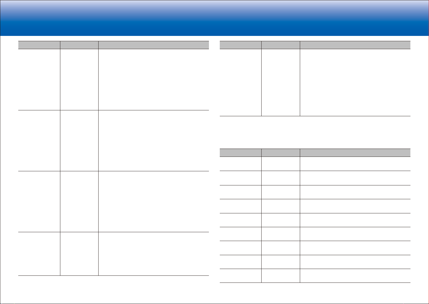
> Specifications > Settings > Listening Modes > Playback Function > Basic Manual
Troubleshooting | Appendix
Setting Item Default Value Setting Details
Height 2 80Hz (THX) Select the crossover frequency from "40Hz" to
"200Hz" to start outputting frequencies for each
channel.
"Full Band": Full band will be output.
•
"Full Band" can be selected only when "Front" is
set to "Full Band".
•
If an item cannot be selected even though
connection is correct, check that the settings in
"Configuration" - "Speaker Channels" matches
the number of connected channels.
Surround 80Hz (THX) Select the crossover frequency from "40Hz" to
"200Hz" to start outputting frequencies for each
channel.
"Full Band": Full band will be output.
•
"Full Band" can be selected only when "Front" is
set to "Full Band".
•
If an item cannot be selected even though
connection is correct, check that the settings in
"Configuration" - "Speaker Channels" matches
the number of connected channels.
Surround Back 80Hz (THX) Select the crossover frequency from "40Hz" to
"200Hz" to start outputting frequencies for each
channel.
"Full Band": Full band will be output.
•
"Full Band" can be selected only when
"Surround" is set to "Full Band".
•
If an item cannot be selected even though
connection is correct, check that the settings in
"Configuration" - "Speaker Channels" matches
the number of connected channels.
LPF of LFE 120Hz Set the low-pass filter for LFE (low-frequency
effect) signals in order to pass lower frequency
signals than the set value and thus cancel
unwanted noises. The low-pass filter will be
effective only on sources with LFE channel.
The value from "80Hz" to "120Hz" can be set.
"Off": Do not use this function
Setting Item Default Value Setting Details
Double Bass On This can be selected only when "Configuration" -
"Subwoofer" is set to other than "No" and "Front" is
set to "Full Band".
Boost bass output by feeding bass sounds from
the front left and right, and center speakers to the
subwoofer.
"On": Bass output will be boosted
"Off": Bass output will not be boosted
•
The setting will not automatically be configured
even if you performed AccuEQ Room
Calibration.
■ 3. Distance
Set the distance from each speaker to the listening position.
Setting Item Default Value Setting Details
Front Left 12' 0" / 3.60 m Specify the distance between each speaker and
the listening position.
Center 12' 0" / 3.60 m Specify the distance between each speaker and
the listening position.
Front Right 12' 0" / 3.60 m Specify the distance between each speaker and
the listening position.
Height 1 Left 9' 0" / 2.70 m Specify the distance between each speaker and
the listening position.
Height 1 Right 9' 0" / 2.70 m Specify the distance between each speaker and
the listening position.
Height 2 Left 9' 0" / 2.70 m Specify the distance between each speaker and
the listening position.
Height 2 Right 9' 0" / 2.70 m Specify the distance between each speaker and
the listening position.
Surround Right 7' 0" / 2.10 m Specify the distance between each speaker and
the listening position.
Surr Back Right 7' 0" / 2.10 m Specify the distance between each speaker and
the listening position.
12
Page 49

> Specifications > Settings > Listening Modes > Playback Function > Basic Manual
Troubleshooting | Appendix
Setting Item Default Value Setting Details
Surr Back Left 7' 0" / 2.10 m Specify the distance between each speaker and
the listening position.
Surround Left 7' 0" / 2.10 m Specify the distance between each speaker and
the listening position.
Subwoofer 1 12' 0" / 3.60 m Specify the distance between each speaker and
the listening position.
Subwoofer 2 12' 0" / 3.60 m Specify the distance between each speaker and
the listening position.
•
Default values vary depending on the regions.
•
Distance units can be switched by pressing Mode on the remote controller. When the unit is set as
feet, you can set between 0' 0" 1/2 and 30' 0" in increments of 1/2. When the unit is set as meters,
you can set between 0.01 m and 9.00 m in increments of 0.01 m.
■ 4. Level Calibration
Setting Item Default Value Setting Details
Front Left 0.0 dB Select a value between "-12.0 dB" and "+12.0
dB" (in 0.5 dB increments). A test tone will be
output each time you change the value. Select the
desired level.
Center 0.0 dB Select a value between "-12.0 dB" and "+12.0
dB" (in 0.5 dB increments). A test tone will be
output each time you change the value. Select the
desired level.
Front Right 0.0 dB Select a value between "-12.0 dB" and "+12.0
dB" (in 0.5 dB increments). A test tone will be
output each time you change the value. Select the
desired level.
Height 1 Left 0.0 dB Select a value between "−12.0 dB" and "+12.0
dB" (in 0.5 dB increments). A test tone will be
output each time you change the value. Select the
desired level.
Height 1 Right 0.0 dB Select a value between "−12.0 dB" and "+12.0
dB" (in 0.5 dB increments). A test tone will be
output each time you change the value. Select the
desired level.
Setting Item Default Value Setting Details
Height 2 Left 0.0 dB Select a value between "−12.0 dB" and "+12.0
dB" (in 0.5 dB increments). A test tone will be
output each time you change the value. Select the
desired level.
Height 2 Right 0.0 dB Select a value between "−12.0 dB" and "+12.0
dB" (in 0.5 dB increments). A test tone will be
output each time you change the value. Select the
desired level.
Surround Right 0.0 dB Select a value between "-12.0 dB" and "+12.0
dB" (in 0.5 dB increments). A test tone will be
output each time you change the value. Select the
desired level.
Surr Back Right 0.0 dB Select a value between "−12.0 dB" and "+12.0
dB" (in 0.5 dB increments). A test tone will be
output each time you change the value. Select the
desired level.
Surr Back Left 0.0 dB Select a value between "−12.0 dB" and "+12.0
dB" (in 0.5 dB increments). A test tone will be
output each time you change the value. Select the
desired level.
Surround Left 0.0 dB Select a value between "-12.0 dB" and "+12.0
dB" (in 0.5 dB increments). A test tone will be
output each time you change the value. Select the
desired level.
Subwoofer 1 0.0 dB Select a value between "−15.0 dB" and "+12.0
dB" (in 0.5 dB increments). A test tone will be
output each time you change the value. Select the
desired level.
Subwoofer 2 0.0 dB Select a value between "−15.0 dB" and "+12.0
dB" (in 0.5 dB increments). A test tone will be
output each time you change the value. Select the
desired level.
■ 5. Dolby Enabled Speaker
13
Page 50

> Specifications > Settings > Listening Modes > Playback Function > Basic Manual
Troubleshooting | Appendix
Setting Item Default Value Setting Details
Dolby Enabled
Speaker to
Ceiling
AccuReflex Off You can enhance the reflection effect of Dolby
•
This setting can be selected when "Configuration" - "Height 1 Speaker"/"Height 2 Speaker" is set to
"Dolby Speaker".
6' 0" / 1.80 m Set the distance between the Dolby Enabled
Speaker and the ceiling. Select between " 0' 0" 1/2
"/"0.01 m" to " 15' 0" "/"4.50 m" (1/2 / 0.01 m units).
•
The unit of distance (feet / meters) shown is the
unit selected for use in "Distance".
Enabled Speakers from the ceiling.
"Off": Do not use this function
"On": Use this function
■ 6. Equalizer Settings
You can adjust the output volume of the range of each connected speaker. You can adjust
the volume of the different sound ranges for each of the speakers. You can set three
different equalizers in Preset 1 to 3. You can select five bands for the Subwoofer and fifteen
bands for all other speakers.
Setting Item Default Value Setting Details
Front 0.0 dB After selecting the speaker frequency from
between 25 Hz" and "16 kHz" with the cursors
, adjust the volume of that frequency between
/
"-6.0 dB" and "+6.0 dB" with / .
Center 0.0 dB After selecting the speaker frequency from
between 25 Hz" and "16 kHz" with the cursors
, adjust the volume of that frequency between
/
"-6.0 dB" and "+6.0 dB" with / .
Height 1 0.0 dB After selecting the speaker frequency from
between 25 Hz" and "16 kHz" with the cursors
, adjust the volume of that frequency between
/
"-6.0 dB" and "+6.0 dB" with / .
Height 2 0.0 dB After selecting the speaker frequency from
between 25 Hz" and "16 kHz" with the cursors
, adjust the volume of that frequency between
/
"-6.0 dB" and "+6.0 dB" with / .
Setting Item Default Value Setting Details
Surround 0.0 dB After selecting the speaker frequency from
between 25 Hz" and "16 kHz" with the cursors
, adjust the volume of that frequency between
/
"-6.0 dB" and "+6.0 dB" with
Surround Back 0.0 dB After selecting the speaker frequency from
between 25 Hz" and "16 kHz" with the cursors
, adjust the volume of that frequency between
/
"-6.0 dB" and "+6.0 dB" with
Subwoofer 0.0 dB After selecting the speaker frequency from
between 25 Hz" and "160 Hz" with the cursors
, adjust the volume of that frequency between
/
"-6.0 dB" and "+6.0 dB" with
•
This cannot be selected if "No" is set in
"Configuration" - "Subwoofer".
•
The result may not be as expected depending on the input source and listening mode setting.
/ .
/ .
/ .
14
Page 51

> Specifications > Settings > Listening Modes > Playback Function > Basic Manual
Troubleshooting | Appendix
■ 7. THX Audio
Setting item Default Value Setting Details
Back Speaker
Spacing
THX Ultra2 /
Select2 Subwoofer
BGC Off If your listening room layout (for practical or
>4.0 ft/>1.2 m Select the distance between the surround back
speakers from "<1.0 ft/<0.3 m", "1.0 - 4.0 ft/0.3 -
1.2 m", and ">4.0 ft/>1.2 m".
•
The unit of distance (feet / meters) shown is the
unit selected for use in "Distance".
•
If an item cannot be selected even though
connection is correct, check that the settings in
"Configuration" - "Speaker Channels" matches
the number of connected channels.
No Set "Yes" or "No" of the connection of the THX
certified subwoofer.
"Yes": When a THX-certified subwoofer is
connected
"No": When a THX-certified subwoofer is not
connected
•
The setting cannot be changed if "Configuration"
- "Subwoofer" is set to "No".
aesthetic reasons) locates most of the listeners
close to the rear wall, the resulting bass level can
be sufficiently reinforced by the boundary that the
overall sound becomes "boomy". THX Ultra2 Plus
receivers contain a Boundary Gain Compensation
(BGC) feature to improve bass balance.
"On": Use this function
"Off": Do not use this function
•
In the following cases, the setting cannot be
changed:
–
"Configulation" - "Subwoofer" is set to "No".
–
"THX Ultra2 / Select2 Subwoofer" is set to
"No".
Setting item Default Value Setting Details
Loudness Plus On When the setting is set to "On", it is possible to
enjoy even subtle nuances of audio expression at
low volume. This is only available when the THX
listening mode is selected.
THX Loudness Plus
THX Loudness Plus is a new volume control
technology featured in THX Ultra2 Plus™ and THX
Select2 Plus™ Certified receivers.
With THX Loudness Plus, home theater audiences
can now experience the rich details in a surround
mix at any volume level.
A consequence of turning the volume below
Reference Level is that certain sound elements
can be lost or perceived differently by the listener.
THX Loudness Plus compensates for the tonal
and spatial shifts that occur when the volume
is reduced by intelligently adjusting ambient
surround channel levels and frequency response.
This enables users experience the true impact
of soundtracks regardless of the volume setting.
THX Loudness Plus is automatically applied when
listening in any THX listening mode. The new THX
Cinema, THX Music, and THX Games modes are
tailored to apply the proper THX Loudness Plus
settings for each type of content.
15
Page 52

> Specifications > Settings > Listening Modes > Playback Function > Basic Manual
Troubleshooting | Appendix
■ 8. EQ for Standing Wave
This controls the affect of the standing waves that occur when sound waves reverberating
off obstacles such as walls interfere with the original sound waves.
Setting Item Default Value Setting Details
Filter 1-3 0.0 dB 1. After selecting the Filter to adjust from "Filter 1"
to "Filter 3" with
2. Select the frequency with
the attenuation with
be selected between "63 Hz" and "250 Hz".
Attenuation can be selected between "0.0 dB"
and "12.0 dB" (0.5 dB intervals).
/ , press Enter.
, then adjust
/
/ . The frequency can
3. Audio Adjust
Make advanced settings such as those related to multiplex audio, settings for the LFE level,
or those related to the volume of this unit.
■ 1. Multiplex/Mono
Setting Item Default Value Setting Details
Multiplex Input
Channel
Mono Input
Channel
Mono Output
Speaker
Main Set the audio channel or language to be output
when playing multiplex audio or multilingual TV
broadcasts etc.
"Main": Main channel only
"Sub": Sub channel only
"Main/Sub": Main and sub channels will be output
at the same time.
•
If multiplex audio is being played, "1+1" will be
displayed when
pressed.
Left + Right Set the input channel to use for playing any 2 ch
digital source such as Dolby Digital, or 2 ch analog/
PCM source in the Mono listening mode.
"Left": Left channel only
"Right": Right channel only
"Left + Right" : Left and right channels
Center Select the speaker to output monaural audio in the
Mono listening mode.
"Center": Audio is output from the center speaker.
"Left/Right": Audio is output from the front L/R
speakers.
•
If an item cannot be selected even though
connection is correct, check that the settings
in "2. Speaker" - "Configuration" - "Speaker
Channels" matches the number of connected
channels.
on the remote controller is
16
Page 53

> Specifications > Settings > Listening Modes > Playback Function > Basic Manual
Troubleshooting | Appendix
■ 2. Dolby
Setting Item Default Value Setting Details
Loudness
Management
On When playing Dolby TrueHD, enable the dialog
normalization function which keeps the volume of
dialog at a certain level. Note that when this setting
is Off, the Late Night function that allows you to
enjoy surround at low volumes is fixed to off when
playing Dolby Digital Plus/Dolby TrueHD.
"On": Use this function
"Off": Do not use this function
■ 3. DTS
Setting Item Default Value Setting Details
DTS Auto
Surround
On When inputting DTS signals that include extended
channel information, the optimum listening mode is
automatically selected according to the extended
information contained in the input signal and the
speaker configuration of this unit when playing in
the straight decoding listening mode.
"On": Use this function
"Off": Audio is played using the same amount
of channels in the input signal according to the
speaker configuration of this unit.
•
The ES Matrix and ES Discrete listening modes
cannot be selected if this function is set to "Off".
■ 4. LFE Level
Set the low-frequency effect (LFE) level for Dolby Digital series, DTS series, Multichannel
PCM, and DSD signals.
Setting Item Default Value Setting Details
LFE Level 0 dB Select the low-frequency effect (LFE) level of each
type of signal from "0dB" to "-∞dB". If the lowfrequency effect sound is too strong, select
"-20dB" or "-∞dB".
17
Page 54

> Specifications > Settings > Listening Modes > Playback Function > Basic Manual
Troubleshooting | Appendix
■ 5. Volume
Setting Item Default Value Setting Details
Volume Display Absolute Switch the volume display between the absolute
value and relative value. The absolute value 82.0 is
equivalent to the relative value 0.0dB.
"Absolute": Absolute value such as "0.5" and "99.5"
"Relative": Relative value such as "-81.5dB" and
"+18.0dB"
•
If the absolute value is set to 82.0, "82.0Ref" will
appear on the display.
Mute Level -∞dB Set the volume lowered from the listening volume
when muting is on. Select a value from "-∞dB",
"-40dB", and "-20dB".
Maximum Volume Off Set the maximum value to avoid too high volume.
Select a value from "Off", "50" to "99". (When
"Volume Display" is set to "Absolute")
Power On Volume Last Set the volume level of when the power is turned
on. Select a value from "Last" (Volume level before
entering standby mode), "Min", "0.5" to "99.5"
and "Max". (When "Volume Display" is set to
"Absolute")
•
You cannot set a higher value than that of
"Maximum Volume".
Headphone Level 0.0 dB Adjust the output level of the headphones. Select a
value between "-12.0 dB" and "+12.0 dB".
18
4. Source
Make settings for input sources, such as volume difference adjustments for each input
selector for the connected equipment.
■ 1. IntelliVolume
Adjust the volume level difference between the devices connected to the unit. Select the
input selector to configure.
Setting Item Default Value Setting Details
IntelliVolume 0.0 dB Select a value between "-12.0 dB" and "+12.0
dB". Set a negative value if the volume of the target
device is larger than the others and a positive
value if smaller. To check the audio, start playback
of the connected device.
•
This function is not effective in Zone 2/Zone 3.
■ 2. Name Edit
Set an easy name to each input. The set name will be shown on the main unit display.
Select the input selector to configure.
Setting Item Default Value Setting Details
Name Edit Input name 1. Select a character or symbol with the cursors
and press Enter.
Repeat it to input 10 or less characters.
"A/a": Switches between upper and lower cases.
(Pressing
toggles between upper and lower cases)
"←" "→": Moves the cursor to the arrow
direction.
" ": Removes a character on the left of the
cursor.
" ": Enters a space.
•
2. After inputting, select "OK" with the cursors and
press Enter.
The input name will be saved.
Mode
on the remote controller also
Pressing Clear on the remote controller will
remove all the input characters.
Page 55

> Specifications > Settings > Listening Modes > Playback Function > Basic Manual
Troubleshooting | Appendix
•
To name a preset radio station, press Tuner on the remote controller, select AM/FM and select the
preset number.
•
This cannot be set if the "NET" input is selected.
■ Audio Select
Select the priority for input selection when multiple audio sources are connected to one
input selector, such as connections to both the "BD/DVD" HDMI IN jack and the "BD/DVD"
AUDIO IN jack. The setting can be separately set to each input selector button. Select the
input selector to configure. Note that there are some default values you cannot change.
Setting Item Default Value Setting Details
Audio Select BD/DVD:
HDMI
CBL/SAT:
HDMI
GAME:
HDMI
STRM BOX:
HDMI
PC:
HDMI
AUX:
HDMI
CD:
OPTICAL
TV:
OPTICAL
PHONO:
Analog
"ARC": When giving priority to input signal from
ARC compatible TV.
•
The setting can be selected only when
"6. Hardware" - "HDMI" - "Audio Return
Channel" is set to "Auto" and also the "TV" input
is selected.
"HDMI": When giving priority to input signal from
HDMI IN jacks
•
The setting can be selected only when the input
is assigned to the HDMI jack in the "1. Input/
Output Assign" - "HDMI Input" setting.
"COAXIAL": When giving priority to input signal
from DIGITIAL IN COAXIAL jacks
•
The setting can be selected only when the input
is assigned to the COAXIAL jack in the "1. Input/
Output Assign" - "Digital Audio Input" setting.
"OPTICAL": When giving priority to input signal
from DIGITIAL IN OPTICAL jacks
•
The setting can be selected only when the input
is assigned to the OPTICAL jack in the "1. Input/
Output Assign" - "Digital Audio Input" setting.
"Analog": To always output analog audio
independently of the input signal
•
The setting can be selected only when the
input is assigned to the AUDIO IN jack in the
"1. Input/Output Assign" - "Analog Audio Input"
setting.
Setting Item Default Value Setting Details
PCM Fixed Mode Off Select whether to fix input signals to PCM (except
multi-channel PCM) when you have selected
"HDMI", "COAXIAL", or "OPTICAL" in the "Audio
Select" setting. Set this item to "On" if noise is
produced or truncation occurs at the beginning of
a track when playing PCM sources. Select "Off"
normally.
•
Changing "Audio Select" changes the setting to
"Off".
•
The setting cannot be changed when "TUNER" or "NET" input is selected.
■ Video Select
When "TUNER" or "NET" input is selected, you can set the input from which video is
displayed on the TV.
Setting Item Default Value Setting Details
Video Select Last "Last": Select the video input played immediately
prior.
"BD/DVD", "CBL/SAT", "GAME", "STRM BOX",
"PC", "AUX", "CD", "TV", "PHONO": Play the video
from the selected input.
•
This setting is effective for an input selector
which is assigned in "1. Input/Output Assign" "HDMI Input" and "Video Input".
•
If the OSD language is set to Chinese, you can only select this setting when "TUNER" is selected as
input.
19
Page 56

> Specifications > Settings > Listening Modes > Playback Function > Basic Manual
Troubleshooting | Appendix
5. Listening Mode Preset
You can preset your favorite listening mode to each input. (For example, you can always
apply straight decode to the Dolby TrueHD source of Blu-ray Disc to play it in unchanged
sound field.)
When the list of input sources is displayed, set the signal type and listening mode.
Although it is possible to select the listening mode during playback, the selected mode will
be reset when the unit enters standby mode.
Setting Item Default Value Setting Details
Analog/PCM All Ch Stereo Set the listening mode for playing PCM signals of
CD and analog signals of record and cassette tape.
Dolby Dolby Surround Set the listening mode for playing Dolby Digital,
Dolby Digital Plus and Dolby TrueHD signals.
•
Input signals are played as they are input if you
select "Straight Decode".
DTS
Other Dolby Surround Set the listening mode for playing audio such as
•
Available listening modes vary depending on speaker configuration and the input signal.
•
Setting "Last Valid" will always select the last selected mode.
•
Only "Analog" can be set to the "TUNER" input.
•
"Digital", "Dolby" and "DSD" can be set to the "NET" input.
DTS Neural:X
Set the listening mode for playing digital audio
signals in DTS and DTS-HD High Resolution
formats. Select the listening mode specified for
Blu-ray or such other DTS-HD Master Audio
source.
•
Input signals are played as they are input if you
select "Straight Decode".
DVD-audio and DSD signals.
•
Input signals are played as they are input if you
select "Straight Decode".
6. Hardware
Make settings related to the HDMI CEC, HDMI Standby Through, ARC features, settings
related to network features, and settings related to power management of the unit, such as
Auto Standby and Network Standby.
■ 1. HDMI
Setting Item Default Value Setting Details
HDMI CEC Off Setting to "On" enables the input selection link and
other link functions with HDMI connected CEC
compliant device.
"On": Use this function
"Off": Do not use this function
When changing this setting, turn off and then on
again the power of all connected components.
•
Depending on the TV set, a link may need to be
configured on the TV.
•
This function is effective only when the device is
connected to the HDMI OUT MAIN terminal.
•
Setting to "On" and closing the on-screen menu
displays the name of the CEC-compatible
components and "CEC On" on the display.
•
Power consumption in standby mode may
increase if "On" is set. (Depending on the TV
status, the unit will enter the normal standby
mode.)
•
If you operate the Master Volume dial on the
main unit when this setting is "On" and audio
is output from the TV speakers, audio will be
output also from the speakers connected to the
unit. If you want to output from only either of
them, change the unit or TV settings, or reduce
the volume of the unit.
•
If abnormal operation occurs when you set the
setting to "On", set it to "Off".
•
When connecting a non-CEC compatible
component, or when you are not sure whether it
is compatible, set the setting to "Off".
20
Page 57

> Specifications > Settings > Listening Modes > Playback Function > Basic Manual
Troubleshooting | Appendix
Setting Item Default Value Setting Details
HDMI Standby
Through
Off When this is set to anything other than "Off",
you can play the video and audio of an HDMI
connected player on the TV even if the unit is in
standby mode. Only "Auto" and "Auto(Eco)" can be
selected if "HDMI CEC" is set to "On". If you select
anything else, set "HDMI CEC" to "Off".
•
Power consumption in standby mode increases
if set to anything other than "Off".
"BD/DVD", "CBL/SAT", "GAME", "STRM BOX",
"PC", "AUX", "CD", "TV", "PHONO": For example,
if you select "BD/DVD", you can play the
equipment connected to the "BD/DVD" jack on the
TV even if the unit is in standby mode. Select this
setting if you have decided which player to use with
this function.
"Last": You can play the video and audio of the
input selected immediately prior to the unit being
switched to standby on the TV.
"Auto", "Auto (Eco)": Select one of these settings
when you have connected equipment that
conforms to the CEC standard. You can play the
video and audio of the input selected on the TV,
irrespective of what input was selected immediately
prior to the unit being switched to standby, using
the CEC link function.
•
To play players on the TV that do not conform to
the CEC standard, you will need to turn the unit
on and switch to the relevant input.
•
When using TV that complies with the
CEC standard, you can reduce the power
consumption in standby mode by selecting
"Auto (Eco)".
Setting Item Default Value Setting Details
Audio TV Out Off You can enjoy audio through the speakers of the
TV while this unit is on.
"On": Use this function
"Off": Do not use this function
•
This setting is fixed to "Auto" if you have set
"1. Input/Output Assign" - "TV Out/OSD" "HDMI Out" or "Other" - "HDMI Out" in the
"Quick Menu" to "MAIN" or "MAIN+SUB" and
"HDMI CEC is set to "On". If you change this
setting, set "HDMI CEC" to "Off".
•
Listening mode cannot be changed while "Audio
TV Out" is set to "On" and audio is being output
through the speakers of the TV.
•
Depending on your TV set or input signal of the
component, audio may not output through the
speakers of the TV even if this setting is set
to "On". In such case, audio is output from the
speakers of the unit.
•
If you operate the Master Volume dial on this
unit when audio that is being input through this
unit for output from the TV speakers, audio
is output from this unit. If you do not want to
output audio from the unit, change the unit or TV
settings, or reduce the volume of the unit.
Audio Return
Channel
Auto LipSync On
Auto (*) You can enjoy sound of the HDMI connected ARC
compatible TV through the speakers connected to
the unit.
*½
To use this function, set "HDMI CEC" to "On" in
advance.
"Auto": When enjoying the TV sound through the
speakers connected to the unit
"Off": When not using the ARC function
This setting automatically corrects any
desynchronization between the video and audio signals
based on data from the HDMI LipSync compatible TV.
"On": Automatic correction will be enabled
"Off": Automatic correction will be disabled
21
Page 58

> Specifications > Settings > Listening Modes > Playback Function > Basic Manual
Troubleshooting | Appendix
■ 2. Network
•
When LAN is configured with a DHCP, set "DHCP" to "Enable" to configure the
setting automatically. ("Enable" is set by default) To assign fixed IP addresses to each
components, you must set "DHCP" to "Disable" and assign an address to this unit in
"IP Address" as well as set information related to your LAN, such as Subnet Mask and
Gateway.
Setting Item Default Value Setting Details
MAC Address ‐ This is the MAC address of this unit.
This value is specific to the component and cannot
be changed.
DHCP Enable "Enable": Auto configuration by DHCP
"Disable": Manual configuration without DHCP
•
If selecting "Disable", you must set "IP Address",
"Subnet Mask", "Gateway", and "DNS Server"
manually.
IP Address 0.0.0.0 Displays/Sets the IP address.
Subnet Mask 0.0.0.0 Displays/Sets the subnet mask.
Gateway 0.0.0.0 Displays/Sets the gateway.
DNS Server 0.0.0.0 Displays/Sets the primary DNS server.
Proxy URL ‐ Displays/Sets the proxy server URL.
Proxy Port 8080 Displays/Sets the proxy server port number when
you enter "Proxy URL".
Setting Item Default Value Setting Details
Friendly Name Integra DRC-R1
XXXXXX
AirPlay Password You can set a password of up to 31 characters so
Change the device name for this unit which is
shown on other devices connected to the network
to an easily recognized name.
1. Press Enter to display the Edit screen.
2. Select a character or symbol with the cursors
and press Enter.
Repeat it to input 31 or less characters.
"A/a": Switches between upper and lower
cases. (Pressing Mode on the remote
controller also toggles between upper and
lower cases.)
"←" "→":
" ":
" ": Enters a space.
•
3. After inputting, select "OK" with the cursors and
press Enter.
The input name will be saved.
that only registered users can use AirPlay
1. Press Enter to display the Edit screen.
2. Select a character or symbol with the cursors
and press Enter.
Repeat it to input 31 or less characters.
"A/a": Switches between upper and lower
cases. (Pressing Mode on the remote
controller also toggles between upper and
lower cases.)
"←" "→":
" ":
" ": Enters a space.
•
•
3. After inputting, select "OK" with the cursors and
press Enter.
The input password will be saved.
Moves the cursor to the arrow direction.
Removes a character on the left of the cursor.
Pressing Clear on the remote controller will
remove all the input characters.
R
.
Moves the cursor to the arrow direction.
Removes a character on the left of the cursor.
To select whether to mask the password
with "*" or display it in plain text, press
Memory on the remote controller.
Pressing Clear on the remote controller will
remove all the input characters.
22
Page 59
> Specifications > Settings > Listening Modes > Playback Function > Basic Manual
Troubleshooting | Appendix
Setting Item Default Value Setting Details
Usage Data No
Network Check ‐ You can check the network connection.
•
Wait for a while if "Network" cannot be selected. It will appear when the network feature is started.
As a means of improving the quality of our products
and services, Onkyo may collect information about
your usage over the network. Select "Yes" if you
agree to our collecting this information. Select "No"
if you do not want us to collect this information.
•
You can set this after confirming the Privacy
Policy. When you select "Usage Data" and
press Enter, the Privacy Policy is displayed.
(The same screen is displayed once also when
setting up the network connection.) If you agree
to the collection of the information, this setting
also becomes "Yes". Note that if you agree
to the Privacy Policy but select "No" for this
setting, the information will not be collected.
Press Enter when "Start" is displayed.
■ 3. Power Management
Setting Item Default Value Setting Details
Sleep Timer Off Allows the unit to enter standby automatically when
the specified time elapses. Select a value from "30
minutes", "60 minutes", and "90 minutes".
"Off": Does not turn the unit to standby
automatically.
Auto Standby On/Off This setting places the unit on standby
automatically after 20 minutes of inactivity without
any video or audio input. (When "Network Standby"
is on, this becomes the Hybrid Standby mode
which reduces the increase in power consumption
to a minimum.)
"On": The unit will automatically enter standby
mode ("AUTO STBY" will light).
"Off": The unit will not automatically enter standby
mode.
•
"Auto Standby" is displayed on the display and
TV screen 30 seconds before the Auto Standby
comes on.
•
"Auto Standby" does not work when Zone 2/
Zone 3 is active.
•
Default values vary depending on the regions.
Auto Standby in
HDMI Standby
Through
Off Enable or disable "Auto Standby" while "HDMI
Standby Through" is on.
"On": The setting will be enabled.
"Off": The setting will be disabled.
•
This setting cannot be set to "On" if "Auto
Standby" and "HDMI Standby Through" are set
to "Off".
23
Page 60

> Specifications > Settings > Listening Modes > Playback Function > Basic Manual
Troubleshooting | Appendix
Setting Item Default Value Setting Details
Network Standby On/Off When this feature is turned "On", you can turn
on the power of the unit via the network using
an application such as Integra Remote that can
control this unit.
•
When "Network Standby" is used, the power
consumption increases even when the unit
is on standby. However, the increase in
power consumption is kept to a minimum by
automatically entering the Hybrid Standby
mode, where only the essential circuit is
operating.
•
"Network Standby", which suppresses power
consumption, may be disabled when the
network connection is lost. Use the power
button on the remote controller or main unit to
turn the unit on if this happens.
•
Default values vary depending on the regions.
Wait for a while if "Network Standby" cannot be selected. It will appear when the network feature is
started.
■ 4. 12V Trigger A
Set when outputting the control signal (maximum 12 V/100 mA) through the 12V TRIGGER
OUT A jack. Different settings can be set for each input selector. You can enable power link
operation when you connect the unit and the external devices equipped with 12V trigger
input jack.
Setting Item Default Value Setting Details
Delay 0 sec Set after how many seconds the 12V trigger output
will occur in response to the unit's operation. As
some devices cause a large current when they turn
on, delay the output if such devices are connected.
Select a value between "0 sec" to "3 sec".
BD/DVD Main
Set the 12V trigger output setting to each input.
"Off": No output
"Main": Output when "BD/DVD" is selected as
for main room.
"Zone 2": Output when "BD/DVD" is selected as
for ZONE2.
input
"Main/Zone 2": Output when "BD/DVD" is selected
as input for main room or ZONE2.
Zone 3": Output when "BD/DVD" is selected as
"
for ZONE3.
input
Main/Zone 3": Output when "BD/DVD" is selected
"
as input for main room or ZONE3.
Zone 2/Zone 3": Output when "BD/DVD" is
"
selected as input for ZONE2 or ZONE3.
Main/Zone 2/Zone 3": Output when "BD/DVD"
"
is selected as input for main room, ZONE2 or
ZONE3.
input
24
Page 61

> Specifications > Settings > Listening Modes > Playback Function > Basic Manual
Troubleshooting | Appendix
Setting Item Default Value Setting Details
CBL/SAT Main
GAME Main
Set the 12V trigger output setting to each input.
"Off": No output
"Main": Output when "
main room.
input for
"Zone 2": Output when "
input for ZONE2.
"Main/Zone 2": Output when "
as input for main room or ZONE2
Zone 3": Output when
"
for ZONE3.
input
Main/Zone 3": Output when
"
as input for main room or ZONE3.
Zone 2/Zone 3": Output when
"
selected as input for ZONE2 or ZONE3.
Main/Zone 2/Zone 3": Output when
"
is selected as input for main room, ZONE2 or
ZONE3.
Set the 12V trigger output setting to each input.
"Off": No output
"Main": Output when "
for main room.
"Zone 2": Output when "
for ZONE2.
"Main/Zone 2": Output when "
input for main room or ZONE2
Zone 3": Output when
"
for ZONE3.
Main/Zone 3": Output when
"
input for main room or ZONE3.
Zone 2/Zone 3": Output when
"
as input for ZONE2 or ZONE3.
Main/Zone 2/Zone 3": Output when
"
is selected as input for main room, ZONE2 or
ZONE3.
CBL/SAT
GAME
" is selected as
CBL/SAT
"CBL/SAT"
GAME
"GAME"
" is selected as
CBL/SAT
.
is selected as
"CBL/SAT"
"CBL/SAT"
" is selected as input
" is selected as input
GAME
.
is selected as
"GAME"
"GAME"
" is selected
is selected
is
"CBL/SAT"
" is selected as
is selected as
"GAME"
input
is selected
Setting Item Default Value Setting Details
STRM BOX Main
PC Main
Set the 12V trigger output setting to each input.
"Off": No output
"Main": Output when "
input for main room.
"Zone 2": Output when "
input for ZONE2.
"Main/Zone 2": Output when "
selected as input for main room or ZONE2
Zone 3": Output when
"
for ZONE3.
input
Main/Zone 3": Output when
"
selected as input for main room or ZONE3.
Zone 2/Zone 3": Output when
"
selected as input for ZONE2 or ZONE3.
Main/Zone 2/Zone 3": Output when
"
is selected as input for main room, ZONE2 or
ZONE3.
Set the 12V trigger output setting to each input.
"Off": No output
"Main": Output when "PC" is selected as input for
main room.
"Zone 2": Output when "PC" is selected as input for
ZONE2.
"Main/Zone 2": Output when "PC" is selected as
input for main room or ZONE2
Zone 3": Output when
"
ZONE3.
Main/Zone 3": Output when
"
input for main room or ZONE3.
Zone 2/Zone 3": Output when
"
input for ZONE2 or ZONE3.
Main/Zone 2/Zone 3": Output when
"
selected as input for main room, ZONE2 or
ZONE3.
STRM BOX
STRM BOX
"STRM BOX"
"PC"
" is selected as
" is selected as
STRM BOX
is selected as
"STRM BOX"
"STRM BOX"
"STRM BOX"
.
is selected as
is selected as
"PC"
is selected as
"PC"
"PC"
" is
is
.
is
is
input
for
25
Page 62
> Specifications > Settings > Listening Modes > Playback Function > Basic Manual
Troubleshooting | Appendix
Setting Item Default Value Setting Details
AUX Main
CD Main
Set the 12V trigger output setting to each input.
"Off": No output
"Main": Output when "
main room
Set the 12V trigger output setting to each input.
"Off": No output
"Main": Output when "CD" is selected as input for
main room.
"Zone 2": Output when "CD" is selected as input for
ZONE2.
"Main/Zone 2": Output when "CD" is selected as
input for main room or ZONE2
Zone 3": Output when
"
ZONE3.
Main/Zone 3": Output when
"
input for main room or ZONE3.
Zone 2/Zone 3": Output when
"
input for ZONE2 or ZONE3.
Main/Zone 2/Zone 3": Output when
"
selected as input for main room, ZONE2 or
ZONE3.
.
" is selected as input for
AUX
.
is selected as
"CD"
is selected as
"CD"
is selected as
"CD"
"CD"
is
input
for
Setting Item Default Value Setting Details
TV Main
PHONO Main
Set the 12V trigger output setting to each input.
"Off": No output
"Main": Output when "TV" is selected as input for
main room.
"Zone 2": Output when "TV" is selected as input for
ZONE2.
"Main/Zone 2": Output when "TV" is selected as
input for main room or ZONE2
Zone 3": Output when
"
ZONE3.
Main/Zone 3": Output when
"
input for main room or ZONE3.
Zone 2/Zone 3": Output when
"
input for ZONE2 or ZONE3.
Main/Zone 2/Zone 3": Output when
"
selected as input for main room, ZONE2 or
ZONE3.
Set the 12V trigger output setting to each input.
"Off": No output
"Main": Output when "
for main room.
"Zone 2": Output when "
input for ZONE2.
"Main/Zone 2": Output when "
as input for main room or ZONE2
Zone 3": Output when
"
for ZONE3.
input
Main/Zone 3": Output when
"
as input for main room or ZONE3.
Zone 2/Zone 3": Output when
"
selected as input for ZONE2 or ZONE3.
Main/Zone 2/Zone 3": Output when
"
is selected as input for main room, ZONE2 or
ZONE3.
.
is selected as
"TV"
"TV"
"TV"
" is selected as input
PHONO
PHONO
PHONO
"PHONO"
"PHONO"
"PHONO"
input
is selected as
is selected as
is
"TV"
" is selected as
" is selected
.
is selected as
is selected
is
"PHONO"
for
26
Page 63
> Specifications > Settings > Listening Modes > Playback Function > Basic Manual
Troubleshooting | Appendix
Setting Item Default Value Setting Details
TUNER Main
NET Main
Set the 12V trigger output setting to each input.
"Off": No output
"Main": Output when "
for main room.
"Zone 2": Output when "
input for ZONE2.
"Main/Zone 2": Output when "
as input for main room or ZONE2
Zone 3": Output when
"
for ZONE3.
input
Main/Zone 3": Output when
"
as input for main room or ZONE3.
Zone 2/Zone 3": Output when
"
selected as input for ZONE2 or ZONE3.
Main/Zone 2/Zone 3": Output when
"
is selected as input for main room, ZONE2 or
ZONE3.
Set the 12V trigger output setting to each input.
"Off": No output
"Main": Output when "
main room.
"Zone 2": Output when "
for ZONE2.
"Main/Zone 2": Output when "
input for main room or ZONE2
Zone 3": Output when
"
for ZONE3.
Main/Zone 3": Output when
"
input for main room or ZONE3.
Zone 2/Zone 3": Output when
"
input for ZONE2 or ZONE3.
Main/Zone 2/Zone 3": Output when
"
selected as input for main room, ZONE2 or
ZONE3.
" is selected as input
TUNER
" is selected as
TUNER
" is selected
TUNER
.
"TUNER"
NET
"NET"
is selected as
"TUNER"
" is selected as input for
" is selected as input
NET
NET
is selected as
"NET"
is selected
"TUNER"
"TUNER"
" is selected as
.
is selected as
is selected as
"NET"
"NET"
is
is
input
■ 5. 12V Trigger B
Set when outputting the control signal (maximum 12 V/25 mA) through the 12V TRIGGER
OUT B jack. Different settings can be set for each input selector. You can enable power link
operation when you connect the unit and the external devices equipped with 12V trigger
input jack.
Setting Item Default Value Setting Details
Delay 1 sec Set after how many seconds the 12V trigger output
will occur in response to the unit's operation. As
some devices cause a large current when they turn
on, delay the output if such devices are connected.
Select a value between "0 sec" to "3 sec".
BD/DVD Zone 2
Set the 12V trigger output setting to each input.
"Off": No output
"Main": Output when "BD/DVD" is selected as
for main room.
"Zone 2": Output when "BD/DVD" is selected as
for ZONE2.
input
"Main/Zone 2": Output when "BD/DVD" is selected
as input for main room or ZONE2.
Zone 3": Output when "BD/DVD" is selected as
"
for ZONE3.
input
Main/Zone 3": Output when "BD/DVD" is selected
"
as input for main room or ZONE3.
Zone 2/Zone 3": Output when "BD/DVD" is
"
selected as input for ZONE2 or ZONE3.
Main/Zone 2/Zone 3": Output when "BD/DVD"
"
is selected as input for main room, ZONE2 or
ZONE3.
input
27
Page 64
> Specifications > Settings > Listening Modes > Playback Function > Basic Manual
Troubleshooting | Appendix
Setting Item Default Value Setting Details
CBL/SAT Zone 2
GAME Zone 2
Set the 12V trigger output setting to each input.
"Off": No output
"Main": Output when "
main room.
input for
"Zone 2": Output when "
input for ZONE2.
"Main/Zone 2": Output when "
as input for main room or ZONE2
Zone 3": Output when
"
for ZONE3.
input
Main/Zone 3": Output when
"
as input for main room or ZONE3.
Zone 2/Zone 3": Output when
"
selected as input for ZONE2 or ZONE3.
Main/Zone 2/Zone 3": Output when
"
is selected as input for main room, ZONE2 or
ZONE3.
Set the 12V trigger output setting to each input.
"Off": No output
"Main": Output when "
for main room.
"Zone 2": Output when "
for ZONE2.
"Main/Zone 2": Output when "
input for main room or ZONE2
Zone 3": Output when
"
for ZONE3.
Main/Zone 3": Output when
"
input for main room or ZONE3.
Zone 2/Zone 3": Output when
"
as input for ZONE2 or ZONE3.
Main/Zone 2/Zone 3": Output when
"
is selected as input for main room, ZONE2 or
ZONE3.
CBL/SAT
GAME
" is selected as
CBL/SAT
"CBL/SAT"
GAME
"GAME"
" is selected as
CBL/SAT
.
is selected as
"CBL/SAT"
"CBL/SAT"
" is selected as input
" is selected as input
GAME
.
is selected as
"GAME"
"GAME"
" is selected
is selected
is
"CBL/SAT"
" is selected as
is selected as
"GAME"
input
is selected
Setting Item Default Value Setting Details
STRM BOX Zone 2
PC Zone 2
Set the 12V trigger output setting to each input.
"Off": No output
"Main": Output when "
input for main room.
"Zone 2": Output when "
input for ZONE2.
"Main/Zone 2": Output when "
selected as input for main room or ZONE2
Zone 3": Output when
"
for ZONE3.
input
Main/Zone 3": Output when
"
selected as input for main room or ZONE3.
Zone 2/Zone 3": Output when
"
selected as input for ZONE2 or ZONE3.
Main/Zone 2/Zone 3": Output when
"
is selected as input for main room, ZONE2 or
ZONE3.
Set the 12V trigger output setting to each input.
"Off": No output
"Main": Output when "PC" is selected as input for
main room.
"Zone 2": Output when "PC" is selected as input for
ZONE2.
"Main/Zone 2": Output when "PC" is selected as
input for main room or ZONE2
Zone 3": Output when
"
ZONE3.
Main/Zone 3": Output when
"
input for main room or ZONE3.
Zone 2/Zone 3": Output when
"
input for ZONE2 or ZONE3.
Main/Zone 2/Zone 3": Output when
"
selected as input for main room, ZONE2 or
ZONE3.
STRM BOX
STRM BOX
"STRM BOX"
"PC"
" is selected as
" is selected as
STRM BOX
is selected as
"STRM BOX"
"STRM BOX"
"STRM BOX"
.
is selected as
is selected as
"PC"
is selected as
"PC"
"PC"
" is
is
.
is
is
input
for
28
Page 65

> Specifications > Settings > Listening Modes > Playback Function > Basic Manual
Troubleshooting | Appendix
Setting Item Default Value Setting Details
AUX Off
CD Zone 2
Set the 12V trigger output setting to each input.
"Off": No output
"Main": Output when "
main room
Set the 12V trigger output setting to each input.
"Off": No output
"Main": Output when "CD" is selected as input for
main room.
"Zone 2": Output when "CD" is selected as input for
ZONE2.
"Main/Zone 2": Output when "CD" is selected as
input for main room or ZONE2
Zone 3": Output when
"
ZONE3.
Main/Zone 3": Output when
"
input for main room or ZONE3.
Zone 2/Zone 3": Output when
"
input for ZONE2 or ZONE3.
Main/Zone 2/Zone 3": Output when
"
selected as input for main room, ZONE2 or
ZONE3.
.
" is selected as input for
AUX
.
is selected as
"CD"
is selected as
"CD"
is selected as
"CD"
"CD"
is
input
for
Setting Item Default Value Setting Details
TV Zone 2
PHONO Zone 2
Set the 12V trigger output setting to each input.
"Off": No output
"Main": Output when "TV" is selected as input for
main room.
"Zone 2": Output when "TV" is selected as input for
ZONE2.
"Main/Zone 2": Output when "TV" is selected as
input for main room or ZONE2
Zone 3": Output when
"
ZONE3.
Main/Zone 3": Output when
"
input for main room or ZONE3.
Zone 2/Zone 3": Output when
"
input for ZONE2 or ZONE3.
Main/Zone 2/Zone 3": Output when
"
selected as input for main room, ZONE2 or
ZONE3.
Set the 12V trigger output setting to each input.
"Off": No output
"Main": Output when "
for main room.
"Zone 2": Output when "
input for ZONE2.
"Main/Zone 2": Output when "
as input for main room or ZONE2
Zone 3": Output when
"
for ZONE3.
input
Main/Zone 3": Output when
"
as input for main room or ZONE3.
Zone 2/Zone 3": Output when
"
selected as input for ZONE2 or ZONE3.
Main/Zone 2/Zone 3": Output when
"
is selected as input for main room, ZONE2 or
ZONE3.
.
is selected as
"TV"
"TV"
"TV"
" is selected as input
PHONO
PHONO
PHONO
"PHONO"
"PHONO"
"PHONO"
input
is selected as
is selected as
is
"TV"
" is selected as
" is selected
.
is selected as
is selected
is
"PHONO"
for
29
Page 66

> Specifications > Settings > Listening Modes > Playback Function > Basic Manual
Troubleshooting | Appendix
Setting Item Default Value Setting Details
TUNER Zone 2
NET Zone 2
Set the 12V trigger output setting to each input.
"Off": No output
"Main": Output when "
for main room.
"Zone 2": Output when "
input for ZONE2.
"Main/Zone 2": Output when "
as input for main room or ZONE2
Zone 3": Output when
"
for ZONE3.
input
Main/Zone 3": Output when
"
as input for main room or ZONE3.
Zone 2/Zone 3": Output when
"
selected as input for ZONE2 or ZONE3.
Main/Zone 2/Zone 3": Output when
"
is selected as input for main room, ZONE2 or
ZONE3.
Set the 12V trigger output setting to each input.
"Off": No output
"Main": Output when "
main room.
"Zone 2": Output when "
for ZONE2.
"Main/Zone 2": Output when "
input for main room or ZONE2
Zone 3": Output when
"
for ZONE3.
Main/Zone 3": Output when
"
input for main room or ZONE3.
Zone 2/Zone 3": Output when
"
input for ZONE2 or ZONE3.
Main/Zone 2/Zone 3": Output when
"
selected as input for main room, ZONE2 or
ZONE3.
" is selected as input
TUNER
" is selected as
TUNER
" is selected
TUNER
.
"TUNER"
NET
"NET"
is selected as
"TUNER"
" is selected as input for
" is selected as input
NET
NET
is selected as
"NET"
is selected
"TUNER"
"TUNER"
" is selected as
.
is selected as
is selected as
"NET"
"NET"
is
is
input
■ 6. 12V Trigger C
Set when outputting the control signal (maximum 12 V/25 mA) through the 12V TRIGGER
OUT C jack. Different settings can be set for each input selector. You can enable power link
operation when you connect the unit and the external devices equipped with 12V trigger
input jack.
Setting Item Default Value Setting Details
Delay 2 sec Set after how many seconds the 12V trigger output
will occur in response to the unit's operation. As
some devices cause a large current when they turn
on, delay the output if such devices are connected.
Select a value between "0 sec" to "3 sec".
BD/DVD Main/Zone 2/
Zone 3
Set the 12V trigger output setting to each input.
"Off": No output
"Main": Output when "BD/DVD" is selected as
for main room.
"Zone 2": Output when "BD/DVD" is selected as
for ZONE2.
input
"Main/Zone 2": Output when "BD/DVD" is selected
as input for main room or ZONE2.
Zone 3": Output when "BD/DVD" is selected as
"
for ZONE3.
input
Main/Zone 3": Output when "BD/DVD" is selected
"
as input for main room or ZONE3.
Zone 2/Zone 3": Output when "BD/DVD" is
"
selected as input for ZONE2 or ZONE3.
Main/Zone 2/Zone 3": Output when "BD/DVD"
"
is selected as input for main room, ZONE2 or
ZONE3.
input
30
Page 67

> Specifications > Settings > Listening Modes > Playback Function > Basic Manual
Troubleshooting | Appendix
Setting Item Default Value Setting Details
CBL/SAT Main/Zone 2/
Zone 3
GAME Main/Zone 2/
Zone 3
Set the 12V trigger output setting to each input.
"Off": No output
"Main": Output when "
main room.
input for
"Zone 2": Output when "
input for ZONE2.
"Main/Zone 2": Output when "
as input for main room or ZONE2
Zone 3": Output when
"
for ZONE3.
input
Main/Zone 3": Output when
"
as input for main room or ZONE3.
Zone 2/Zone 3": Output when
"
selected as input for ZONE2 or ZONE3.
Main/Zone 2/Zone 3": Output when
"
is selected as input for main room, ZONE2 or
ZONE3.
Set the 12V trigger output setting to each input.
"Off": No output
"Main": Output when "
for main room.
"Zone 2": Output when "
for ZONE2.
"Main/Zone 2": Output when "
input for main room or ZONE2
Zone 3": Output when
"
for ZONE3.
Main/Zone 3": Output when
"
input for main room or ZONE3.
Zone 2/Zone 3": Output when
"
as input for ZONE2 or ZONE3.
Main/Zone 2/Zone 3": Output when
"
is selected as input for main room, ZONE2 or
ZONE3.
CBL/SAT
GAME
" is selected as
CBL/SAT
"CBL/SAT"
GAME
"GAME"
" is selected as
CBL/SAT
.
is selected as
"CBL/SAT"
"CBL/SAT"
" is selected as input
" is selected as input
GAME
.
is selected as
"GAME"
"GAME"
" is selected
is selected
is
"CBL/SAT"
" is selected as
is selected as
"GAME"
input
is selected
Setting Item Default Value Setting Details
STRM BOX Main/Zone 2/
Zone 3
PC Main/Zone 2/
Zone 3
Set the 12V trigger output setting to each input.
"Off": No output
"Main": Output when "
input for main room.
"Zone 2": Output when "
input for ZONE2.
"Main/Zone 2": Output when "
selected as input for main room or ZONE2
Zone 3": Output when
"
for ZONE3.
input
Main/Zone 3": Output when
"
selected as input for main room or ZONE3.
Zone 2/Zone 3": Output when
"
selected as input for ZONE2 or ZONE3.
Main/Zone 2/Zone 3": Output when
"
is selected as input for main room, ZONE2 or
ZONE3.
Set the 12V trigger output setting to each input.
"Off": No output
"Main": Output when "PC" is selected as input for
main room.
"Zone 2": Output when "PC" is selected as input for
ZONE2.
"Main/Zone 2": Output when "PC" is selected as
input for main room or ZONE2
Zone 3": Output when
"
ZONE3.
Main/Zone 3": Output when
"
input for main room or ZONE3.
Zone 2/Zone 3": Output when
"
input for ZONE2 or ZONE3.
Main/Zone 2/Zone 3": Output when
"
selected as input for main room, ZONE2 or
ZONE3.
STRM BOX
STRM BOX
"STRM BOX"
"PC"
" is selected as
" is selected as
STRM BOX
is selected as
"STRM BOX"
"STRM BOX"
"STRM BOX"
.
is selected as
is selected as
"PC"
is selected as
"PC"
"PC"
" is
is
.
is
is
input
for
31
Page 68

> Specifications > Settings > Listening Modes > Playback Function > Basic Manual
Troubleshooting | Appendix
Setting Item Default Value Setting Details
AUX Main
CD Main/Zone 2/
Zone 3
Set the 12V trigger output setting to each input.
"Off": No output
"Main": Output when "
main room
Set the 12V trigger output setting to each input.
"Off": No output
"Main": Output when "CD" is selected as input for
main room.
"Zone 2": Output when "CD" is selected as input for
ZONE2.
"Main/Zone 2": Output when "CD" is selected as
input for main room or ZONE2
Zone 3": Output when
"
ZONE3.
Main/Zone 3": Output when
"
input for main room or ZONE3.
Zone 2/Zone 3": Output when
"
input for ZONE2 or ZONE3.
Main/Zone 2/Zone 3": Output when
"
selected as input for main room, ZONE2 or
ZONE3.
.
" is selected as input for
AUX
.
is selected as
"CD"
is selected as
"CD"
is selected as
"CD"
"CD"
is
input
for
Setting Item Default Value Setting Details
TV Main/Zone 2/
Zone 3
PHONO Main/Zone 2/
Zone 3
Set the 12V trigger output setting to each input.
"Off": No output
"Main": Output when "TV" is selected as input for
main room.
"Zone 2": Output when "TV" is selected as input for
ZONE2.
"Main/Zone 2": Output when "TV" is selected as
input for main room or ZONE2
Zone 3": Output when
"
ZONE3.
Main/Zone 3": Output when
"
input for main room or ZONE3.
Zone 2/Zone 3": Output when
"
input for ZONE2 or ZONE3.
Main/Zone 2/Zone 3": Output when
"
selected as input for main room, ZONE2 or
ZONE3.
Set the 12V trigger output setting to each input.
"Off": No output
"Main": Output when "
for main room.
"Zone 2": Output when "
input for ZONE2.
"Main/Zone 2": Output when "
as input for main room or ZONE2
Zone 3": Output when
"
for ZONE3.
input
Main/Zone 3": Output when
"
as input for main room or ZONE3.
Zone 2/Zone 3": Output when
"
selected as input for ZONE2 or ZONE3.
Main/Zone 2/Zone 3": Output when
"
is selected as input for main room, ZONE2 or
ZONE3.
.
is selected as
"TV"
"TV"
"TV"
" is selected as input
PHONO
PHONO
PHONO
"PHONO"
"PHONO"
"PHONO"
input
is selected as
is selected as
is
"TV"
" is selected as
" is selected
.
is selected as
is selected
is
"PHONO"
for
32
Page 69

> Specifications > Settings > Listening Modes > Playback Function > Basic Manual
Troubleshooting | Appendix
Setting Item Default Value Setting Details
TUNER Main/Zone 2/
Zone 3
NET Main/Zone 2/
Zone 3
Set the 12V trigger output setting to each input.
"Off": No output
"Main": Output when "
for main room.
"Zone 2": Output when "
input for ZONE2.
"Main/Zone 2": Output when "
as input for main room or ZONE2
Zone 3": Output when
"
for ZONE3.
input
Main/Zone 3": Output when
"
as input for main room or ZONE3.
Zone 2/Zone 3": Output when
"
selected as input for ZONE2 or ZONE3.
Main/Zone 2/Zone 3": Output when
"
is selected as input for main room, ZONE2 or
ZONE3.
Set the 12V trigger output setting to each input.
"Off": No output
"Main": Output when "
main room.
"Zone 2": Output when "
for ZONE2.
"Main/Zone 2": Output when "
input for main room or ZONE2
Zone 3": Output when
"
for ZONE3.
Main/Zone 3": Output when
"
input for main room or ZONE3.
Zone 2/Zone 3": Output when
"
input for ZONE2 or ZONE3.
Main/Zone 2/Zone 3": Output when
"
selected as input for main room, ZONE2 or
ZONE3.
" is selected as input
TUNER
" is selected as
TUNER
" is selected
TUNER
.
"TUNER"
NET
"NET"
is selected as
"TUNER"
" is selected as input for
" is selected as input
NET
NET
is selected as
"NET"
is selected
"TUNER"
"TUNER"
" is selected as
.
is selected as
is selected as
"NET"
"NET"
is
is
input
7. Multi Zone
Make settings related to Multi-zone Connection, such as the volume for the separate room.
■ 1. Zone 2
Setting Item Default Value Setting Details
Output Level Fixed Select which of the integrated amplifier in a
separate room or this unit should be used to adjust
the volume when Zone 2 is active.
"Fixed": Adjust on the Integrated amplifier in a
separate room
"Variable": Adjust on the unit
Maximum Volume Off Set the maximum value for Zone 2 to avoid too
high volume. Select a value from "Off", "50" to
"99". (When "3. Audio Adjust" - "Volume" - "Volume
Display" is set to "Absolute")
Power On Volume Last Set the Zone 2 volume level of when this unit is
turned on. Select a value from "Last" (Volume level
when the unit was turned off), "Min", "0.5" to "99.5"
and "Max". (When "3. Audio Adjust" - "Volume" "Volume Display" is set to "Absolute")
•
You cannot set a higher value than that of
"Maximum Volume".
■ 2. Zone 3
Setting Item Default Value Setting Details
Output Level Fixed Select which of the integrated amplifier in a
separate room or this unit should be used to adjust
the volume when Zone 3 is active.
"Fixed": Adjust on the Integrated amplifier in a
separate room
"Variable": Adjust on the unit
Maximum Volume Off Set the maximum value for Zone 3 to avoid too
high volume. Select a value from "Off", "50" to
"99". (When "3. Audio Adjust" - "Volume" - "Volume
Display" is set to "Absolute")
33
Page 70

> Specifications > Settings > Listening Modes > Playback Function > Basic Manual
Troubleshooting | Appendix
Setting Item Default Value Setting Details
Power On Volume Last Set the Zone 3 volume level of when this unit is
turned on. Select a value from "Last" (Volume level
when the unit was turned off), "Min", "0.5" to "99.5"
and "Max". (When "3. Audio Adjust" - "Volume" "Volume Display" is set to "Absolute")
•
You cannot set a higher value than that of
"Maximum Volume".
8. Miscellaneous
Change the frequency step for the tuner, update the firmware, and perform Initial Setup,
etc.
■ 1. Tuner
Setting Item Default Value Setting Details
AM / FM
Frequency Step
(North American
models)
AM Frequency
Step (Australian
and Asian
models)
10 kHz / 0.2 MHz
9 kHz
Select a frequency step depending on your area of
residence.
Select "10 kHz/0.2 MHz" or "9 kHz/0.05 MHz".
•
When this setting is changed, all radio presets
are deleted.
Select a frequency step depending on your area of
residence.
Select "10 kHz" or "9 kHz".
•
When this setting is changed, all radio presets
are deleted.
34
Page 71

> Specifications > Settings > Listening Modes > Playback Function > Basic Manual
Troubleshooting | Appendix
■ 2. Remote ID
Setting Item Default Value Setting Details
Remote ID 1 Select an ID for the unit's remote controller from
"1", "2", and "3" to prevent interference between
the unit and other Integra/ONKYO components that
are installed in the same room. After changing the
ID on the main unit, change the ID on the remote
controller accordingly with the following procedure.
While holding down Mode, press the following
numeric buttons for about 3 seconds.
•
To change the remote controller ID to "1":
(The remote indicator flashes once.)
•
To change the remote controller ID to "2":
(The remote indicator flashes twice.)
•
To change the remote controller ID to "3":
(The remote indicator flashes three times.)
■ 3. Firmware Update
Setting Item Default Value Setting Details
Update Notice Enable Availability of a firmware update will be notified via
network.
"Enable": Notify updates
"Disable": Do not notify updates
Version ‐ The current firmware version will be displayed.
Update via
NET
Update via
USB
•
Wait for a while if "Firmware Update" cannot be selected. It will appear when the network feature is
started.
‐ Press Enter to select when you want to update the
firmware via network.
•
You will not be able to select this setting if you
do not have Internet access or there is nothing
to update.
‐ Press Enter to select when you want to update the
firmware via USB.
•
You will not be able to select this setting if a
USB storage device is not connected or there is
nothing to update in the USB storage device.
■ 4. Initial Setup
You can make the initial setup from the setup menu.
•
Wait for a while if "Initial Setup" cannot be selected. It will appear when the network
feature is started.
■ 5. Lock
Setting Item Default Value Setting Details
Setup Parameter Unlocked Lock the Setup menu to protect the settings.
"Locked": The menu is locked.
"Unlocked": The menu is unlocked.
35
Page 72

> Specifications > Settings > Listening Modes > Playback Function > Basic Manual
Setup Mic
•
Calibration takes between 3 to 12 minutes to be
When you turn the unit on for the first time after purchasing
it, Initial Setup is automatically shown on the TV to enable
you to make settings required for startup using simple
operations following onscreen guidance.
Operation:
Select the item with the cursors of the remote controller
and press Enter to confirm your selection. To return to the
previous screen, press
To redo Initial Setup:
If you terminate the procedure on the way or want to
change a setting made during Initial Setup, press
remote controller, select "8. Miscellaneous" - "Initial Setup",
and press Enter.
Place the supplied speaker setup microphone in the
listening position, measure the test tones emitted by the
speakers, then the unit automatically sets the optimum
volume level for each speaker, the crossover frequencies,
and the distance from the listening position. This also
reduces the influence of standing waves to suit the
listening environment, automatically adjusts the equalizers
for the speakers, and enables correction of distortion
caused by the acoustic environment of the room.
36
Initial Setup
Initial Setup
Language Select
English
Deutsch
Français
Español
Italiano
Nederlands
Svenska
Русский язык
˹୫
.
■ 1. AccuEQ Room Calibration
completed. The speakers emit the test tone at high
volume during measurement, so be careful of your
surroundings. Keep the room as quiet as possible
during measurement.
•
When using THX certified speakers, THX recommends
setting the crossover frequency to "80Hz(THX)". It is
also recommended to manually adjust the settings for
each speaker to suit the specific characteristics of each
room.
1. Place the supplied speaker setup microphone in the
listening position, and connect to the Setup Mic jack on
the main unit.
The image on the screen changes as you choose the
number of channels in "Speaker Channels", so refer to it
when performing the settings.
Also use this screen to select whether you have connected
a subwoofer and to select the type of height speaker, etc.
•
If you have connected a subwoofer, check the power
and volume of the subwoofer. Set the subwoofer
volume to more than halfway.
Exit
3. Test tones are emitted by the speakers, and firstly the
unit detects the speakers connected and the noise in
the environment.
4. After the results of the above measurements are
displayed, select "Next", press Enter on the remote
controller, and the test tones are emitted again, and the
unit automatically makes settings such as the optimum
volume level and the crossover frequency.
on the
When putting the speaker setup microphone on a
tripod, refer to the illustration when putting it in place.
•
To cancel AccuEQ Room Calibration partway
5. Select whether to enable or disable the equalizer
function that corrects for distortion caused by the
acoustic environment of the room.
through, disconnect the speaker setup microphone.
2. Select the connected speaker configuration.
If this is to be enabled, then normally you should
select "On (All Channels)", and to disable just the front
AccuEQ Room Calibration
Speaker Channels
Subwoofer
Height 1 Speaker
Height 2 Speaker
Bi-Amp
Select how many speakers you have.
AccuEQ Room Calibration
To enable equalizer for each speakers, select "On".
Please select "All Channels", if you have same speakers for all
channels. Please select "Except Front Left / Right", if front
speakers are larger than other speakers.
On (All Channels)
On (Except Front Left / Right)
Off
7.1.4 ch
2ch
Top Front
Top Rear
No
< >
Troubleshooting | Appendix
Next
Next
Page 73

> Specifications > Settings > Listening Modes > Playback Function > Basic Manual
Troubleshooting | Appendix
speakers you should select "On (Except Front Left /
Right)".
6. Disconnect the speaker setup microphone. You cannot
use any other menu options while it is connected.
■ 2. Source Connection
Check that each input source is connected correctly.
Follow the guidance, select the input you want to confirm,
start play of the selected player, and confirm that the
images appear on the TV and that sound is played.
■ 3. Network Connection
You can check the network connection status.
•
A confirmation screen asking you to agree to the privacy
policy is displayed during network setting. Select "Yes"
and press Enter to indicate agreement.
■ 4. Multi Zone Setup
Make these settings to enjoy video and audio in a room
other than the main room (ZONE 2/ZONE 3).
Select "with External Premain Amplifier" when connecting
a pre-main amplifier in the separate room. Select "with
External Power Amplifier" when connecting a power
amplifier.
If you are going to be connecting a TV in the separate
room (ZONE 2), then when "Would you be using TV in 2nd
room?" is displayed, select "Yes".
■ 5. Audio Return Channel
If you have connected a TV that supports ARC, select
"Yes". This unit's ARC setting turns on and you can listen
to the TV's audio through this unit.
•
If you select "Yes", the HDMI CEC function is enabled
and power consumption increases during standby.
37
Page 74
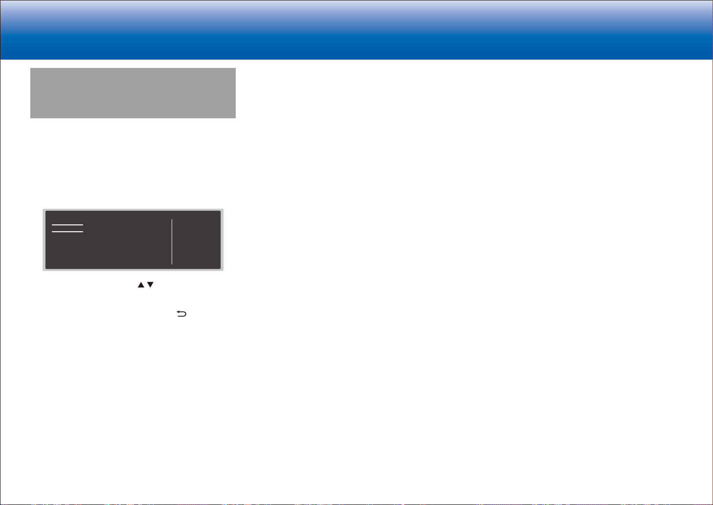
> Specifications > Settings > Listening Modes > Playback Function > Basic Manual
Troubleshooting | Appendix
Quick Menu
You can quickly adjust settings you frequently use, such as
tone adjustments, etc.
Operation:
You can make the settings on the TV screen while playing
something. Press Q on the remote controller to display the
Quick Menu.
Quick Menu
Tone
Level
AccuEQ
Other
Bass
Treble
Select the item with the cursor / buttons of the remote
controller and press Enter to confirm your selection.
Use the cursors to change the settings.
•
To return to the previous screen, press .
•
To exit the settings, press Q.
■ Tone
Bass:
Enhance or moderate the bass range of all channels
except the subwoofer channel.
Treble:
Enhance or moderate the treble range of all channels
except the subwoofer channel.
•
It cannot be set if the listening mode is Direct or THX.
■ Level
Center:
Adjust the speaker level of the center speaker while
38
BD/DVD
listening to some sound.
Subwoofer 1 / Subwoofer 2:
Adjust the speaker level of the subwoofer while listening to
some sound.
•
The adjustment you made will be reset to the previous
status when you turn the unit to standby mode.
■ AccuEQ
AccuEQ Room Calibration:
Enable or disable the equalizer function that corrects for
distortion caused by the acoustic environment of the room.
If this is to be enabled, then normally you should select
"On (All Ch)", and to disable just the front speakers you
should select "On (ex. L/R)". The setting can be separately
set to each input selector.
Equalizer:
Select "Preset 1" to "Preset 3" configured in "2. Speaker" "Equalizer Settings" in the Setup menu. The same sound
field setting is applied all ranges when set to "Off".
EQ for Standing Wave :
Select whether to enable or disable the standing wave
control calibrated in "2. Speaker" - "EQ for Standing Wave"
in the Setup menu.
•
It cannot be set if the listening mode is Pure Direct.
Re-EQ, Re-EQ(THX):
Adjust the soundtrack that was processed to enhance
its high pitch range, in order to make it suitable for home
theater.
In Re-EQ, the following listening modes can be used:
Dolby Digital, Dolby Digital Plus, Dolby Surround, Dolby
TrueHD, Multichannel, DTS, DTS-ES, DTS 96/24, DTSHD High Resolution Audio, DTS-HD Master Audio, DTS
Neural:X, DTS Express, and DSD.
In Re-EQ(THX), the following listening modes can be used:
THX Cinema, and THX Ultra2 Cinema.
•
It cannot be set if the listening mode is Direct.
■ Other
A/V Sync :
If the video is behind the audio, you can delay the audio to offset
the gap. Different settings can be set for each input selector.
•
It cannot be set if the listening mode is Direct.
Music Optimizer:
Improve the quality of the compressed audio. Playback
sound of lossy compressed files such as MP3 will be
improved. The setting can be separately set to each input
selector. The setting is effective with 2 ch signals with a
sampling frequency of 48 kHz or less. The setting is not
effective in the bitstream signals. This function works in
the Stereo, Mono, All Ch Stereo, and Full Mono listening
modes.
Late Night:
Make small sounds easily heard. It is useful when you
need to reduce the volume while watching a movie late
night. You can enjoy the effect only when playing Dolby
series and DTS series input signals.
•
The setting cannot be used in the following cases.
–
If "Loudness Management" is set to "Off" when
playing Dolby Digital Plus or Dolby TrueHD
–
When the input signal is DTS:X and "Dialog Control"
is other than 0 dB
Center Spread:
Adjust the width of the sound field of the front channel
when playing in the Dolby Surround listening mode. To
spread the width of the sound field to the left and right, set
to "On". To concentrate sound in the center, set to "Off".
•
Depending on the speaker settings, this becomes "Off".
Dialog Control:
You can increase the dialog portion of the audio in 1 dB
steps up to 6 dB so that you can make dialog easier to
hear over background noise.
•
This cannot be set for content other than DTS:X.
•
The effect may not be selectable with some content.
Screen Centered Dialog:
Front high speakers are used to move acoustic images
such as dialogs from the center speakers upward
according to the height of the TV screen. Acoustic images
of the center speakers move up as the set value is
increased.
Page 75

> Specifications > Settings > Listening Modes > Playback Function > Basic Manual
Troubleshooting | Appendix
•
Depending on the speaker settings, this becomes "Off".
•
This item may not be available depending on the source
being played and the selected listening mode.
HDMI Out:
Allows you to select the HDMI jack to output video signals
from "MAIN", "SUB", and "MAIN+SUB".
39
Page 76

> Specifications > Settings > Listening Modes > Playback Function > Basic Manual
Signal flow
Troubleshooting | Appendix
Control Function Settings
You can enable the control functions between the unit and
external devices. Special devices or cable connections are
necessary to enable the functions. For more information
about installation, contact a store specializing in these
products.
■ RS232 port
Use this port for connection with an integrated control
system that can enable home automation. Some integrated
control systems provide a centralized operation with a
single touch panel controller in order to control audio and
video home appliances and security devices together. For
more information about adopting an integrated control
system, contact the specialized stores.
■ IR jack
If you use a commercially available multiroom remote
control kit with this jack, you can operate the unit with
the remote controller even when you are in a separate
room, or operate the unit with the remote controller even
if its remote control sensor is difficult to see. You can also
connect a device with the unit and operate it with the
remote controller.
Connecting
This unit
•
Other companies may use indications other than IR
on their products. Confirm in the instruction manual
included with your components.
•
Refer to the instruction manual of the IR receiver for the
types of cables required for connection.
block
IR receiver
Remote
controller
ZoneMain room
■ 12V trigger output jack
You can enable power link operation when you connect
the unit and an external device such as power amplifier
equipped with 12V trigger input jack. When the desired
input is selected on the unit, power link operation will be
activated with a control signal of maximum 12 V/100 mA
from the 12V TRIGGER OUT A jack or maximum 12 V/25
mA when using the 12V TRIGGER OUT B or C jack. You
can select the zone to output the control signal by setting
each of the inputs. For connection, use a monaural mini
plug cable.
40
Page 77
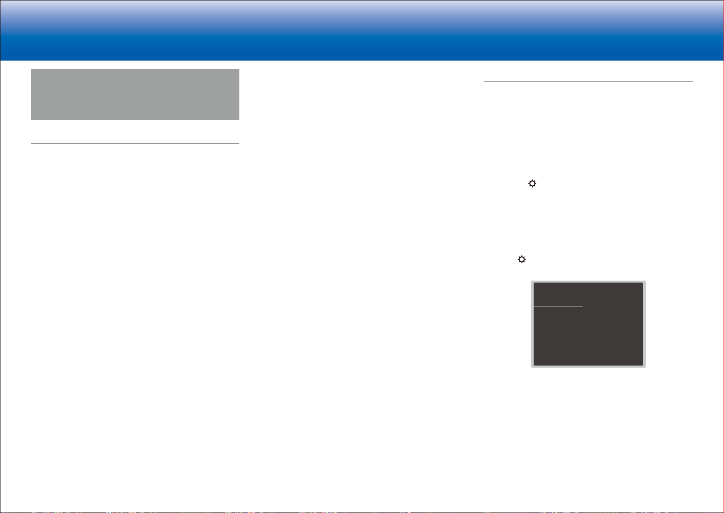
> Specifications > Settings > Listening Modes > Playback Function > Basic Manual
Troubleshooting | Appendix
Firmware Update
About Firmware Update
There are two methods for updating the firmware: via
network and via USB.
Use the one that best suits your environment.
•
For the latest information on updates, visit our
company's website. There is no need to update the
firmware on this unit if there is no update available.
•
Before updating, make sure that the speaker setup
microphone is not connected.
•
During an update, do not
–
Disconnect and reconnect any cable, USB storage
device, speaker setup microphone or headphones,
or perform any operation on the component such as
turn off its power
–
Accessing this unit from a PC or smartphone using
an application
•
The update may take about 20 minutes to complete for
either method: via network or via USB. Furthermore,
existing settings are guaranteed regardless of the
method used for update.
Note that when this unit is connected to a network, you
may see notifications about firmware updates on the
display. To execute updating, select "Update Now" with the
cursor buttons of the remote controller and press Enter.
The unit automatically turns itself into standby mode after
"Completed!" appears on the display, and updating will be
complete.
online documentation, regardless of legal theory, and
whether arising in tort or contract.
In no event will our company be liable to you or any third
party for any special, indirect, incidental, or consequential
damages of any kind, including, but not limited to,
compensation, reimbursement or damages on account of
the loss of present or prospective profits, loss of data, or
for any other reason whatsoever.
Updating the Firmware via Network
Preparation:
•
Check that the unit is turned on, and the connection to
the Internet is secured.
•
Turn off the controller component (PC etc.) connected
to the network.
•
Stop any playing Internet radio, USB storage device, or
server content.
•
If the multi-zone function is active, turn it off.
•
If "HDMI CEC" is set to "On", set it to "Off".
–
Press
on the remote controller. Then, after
selecting "6. Hardware" - "HDMI" and pressing Enter,
select "HDMI CEC" and select "Off".
* The description may differ from the on-screen display but that will not
change the way to operate or the function.
■ Update
1. Press on the remote controller.
The Setup menu is displayed on the TV screen.
Setup
1. Input/Output Assign
2. Speaker
3. Audio Adjust
4. Source
5.
Listening Mode Preset
6. Hardware
7. Multi Zone
8. Miscellaneous
2. Select "8. Miscellaneous" - "Firmware Update" "Update via NET" with the cursors in order, then press
Enter.
1. TV Out / OSD
2. HDMI Input
3. Video Input
4. Digital Audio Input
5. Analog Audio Input
Disclaimer: The program and accompanying online
documentation are furnished to you for use at your own
risk.
Our company will not be liable and you will have no
remedy for damages for any claim of any kind whatsoever
concerning your use of the program or the accompanying
41
Page 78
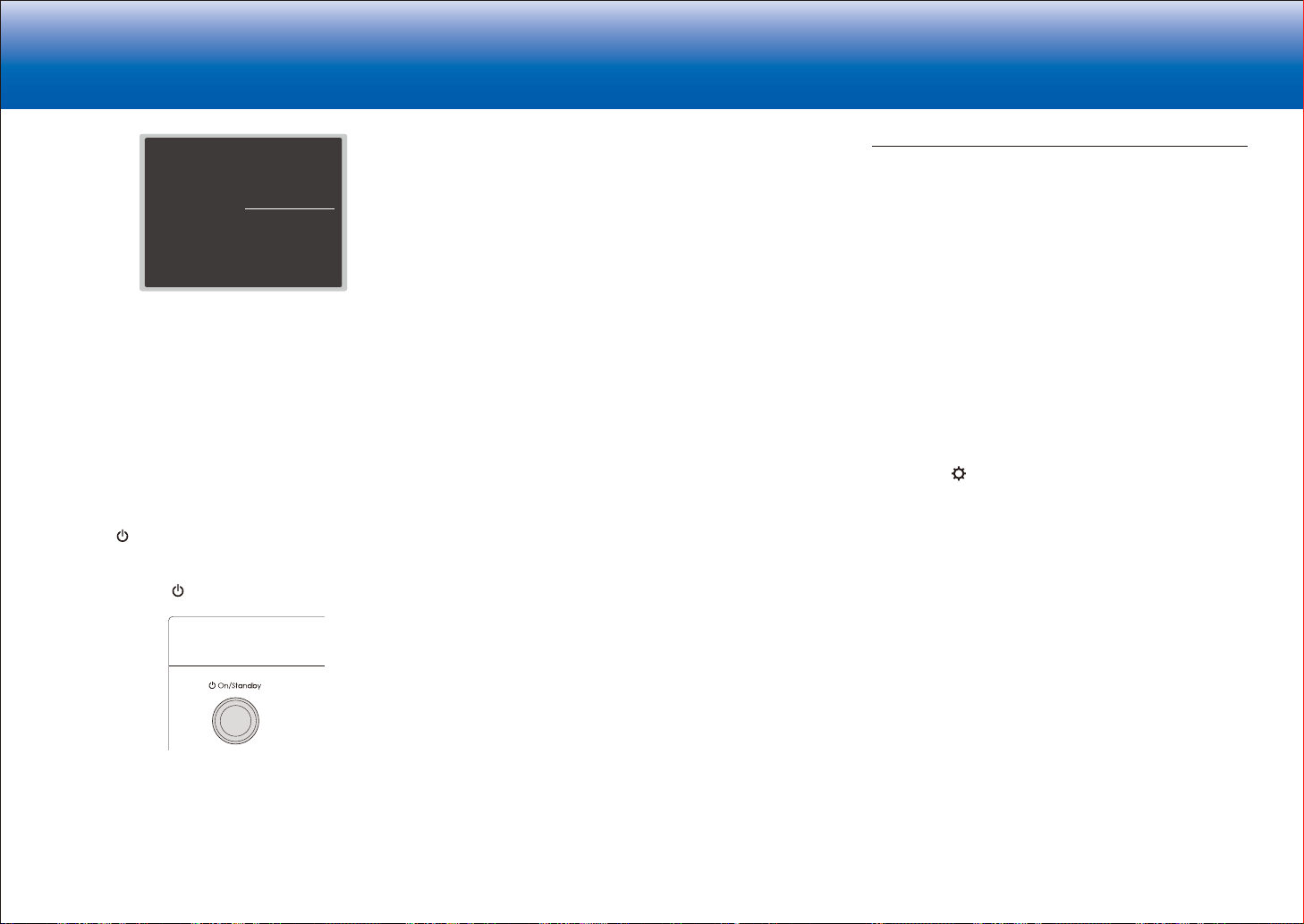
> Specifications > Settings > Listening Modes > Playback Function > Basic Manual
Troubleshooting | Appendix
•
Setup
Setup
1. Input/Output Assign
1. Input/Output Assign
2. Speaker
2. Speaker
3. Audio Adjust
3. Audio Adjust
4. Source
4. Source
5.
Listening Mode Preset
5.
Listening Mode Preset
6. Hardware
6. Hardware
7. Multi Zone
7. Multi Zone
8. Miscellaneous
8. Miscellaneous
•
If "Firmware Update" is grayed out and cannot be
1. Tuner
1. Tuner
2. Remote ID
2. Remote ID
3. Preamp Mode
3. Firmware Update
4. Firmware Update
4. Initial Setup
5. Initial Setup
5. Lock
6. Lock
selected, wait for a while until it starts up.
•
You will not be able to select "Update via NET" if
there is nothing to update.
3. Press Enter with "Update" selected to start update.
•
During the update, the TV screen may go black
depending on the updated program. In that case,
check the progress on the display of the unit. The
TV screen will remain black until the update is
complete and the power is turned on again.
•
"Completed!" is displayed when the update is
complete.
4. Press
On/Standby on the main unit to turn the unit
into standby mode. The process is completed and your
firmware is updated to the latest version.
•
Do not use on the remote controller.
*-01, *-10:
Ethernet cable not found. Connect the Ethernet cable
properly.
•
*-02, *-03, *-04, *-05, *-06, *-11, *-13, *-14, *
-16, *-17, *-18, *-20, *-21:
Internet connection error. Check the following:
–
The router is turned on
–
This unit and the router are connected via the
network
Try to disconnect and then connect again the power
to the unit and router. This may solve the problem. If
you are still unable to connect to the Internet, the DNS
server or proxy server may be temporarily down. Check
the service status with your ISP provider.
•
Others
Disconnect then reconnect the AC power cord, then
repeat from the beginning.
Updating via USB
Preparation:
•
Prepare a 128MB or larger USB storage device. FAT16
or FAT32 file system format.
–
Media inserted in a USB card reader may not be
used for this function.
–
USB storage devices with security function are not
supported.
–
USB hubs and USB devices with hub function are
not supported. Do not connect these devices to the
unit.
•
Delete any data stored on the USB storage device.
•
Turn off the controller component (PC etc.) connected
to the network.
•
Stop any playing Internet radio, USB storage device, or
server content.
•
If the multi-zone function is active, turn it off.
•
If "HDMI CEC" is set to "On", set it to "Off".
–
Press
selecting "6. Hardware" - "HDMI" and pressing Enter,
select "HDMI CEC" and select "Off".
* Some USB storage devices may take long to load, may not be loaded
correctly, or may not be correctly fed depending on the device or their
content.
* Our company will not be liable whatsoever for any loss or damage of
data, or storage failure arising from the use of the USB storage device
with this unit. Thank you for your understanding.
* The description may differ from the on-screen display but that will not
change the way to operate or the function.
on the remote controller. Then, after
■ If an Error Message is Displayed
When an error occurs, "*-** Error!" is displayed on
the display of the unit. ("*" represents an alphanumeric
character.) Check the following:
Error Code
42
■ Update
1. Connect the USB storage device to your PC.
2. Download the firmware file from our company's website
to your PC and unzip.
Firmware files are named in the following way:
ONKAVR****_************.zip
Unzip the file on your PC. The number of unzipped files
and folders varies depending on the model.
3. Copy all unzipped files and folders to the root folder of
the USB storage device.
•
Make sure to copy the unzipped files.
Page 79

> Specifications > Settings > Listening Modes > Playback Function > Basic Manual
Troubleshooting | Appendix
4. Connect the USB storage device to the USB port of the
unit.
•
If you connect a USB hard disk drive to the USB
port of the unit, we recommend that you use its AC
adapter to power it.
•
If the USB storage device has been partitioned,
each section will be treated as an independent
device.
5. Press
on the remote controller.
The Setup menu is displayed on the TV screen.
Setup
1. Input/Output Assign
2. Speaker
3. Audio Adjust
4. Source
5.
Listening Mode Preset
6. Hardware
7. Multi Zone
8. Miscellaneous
1. TV Out / OSD
2. HDMI Input
3. Video Input
4. Digital Audio Input
5. Analog Audio Input
6. Select "8. Miscellaneous" - "Firmware Update" "Update via USB" with the cursors in order, then press
Enter.
Setup
Setup
1. Input/Output Assign
1. Input/Output Assign
2. Speaker
2. Speaker
3. Audio Adjust
3. Audio Adjust
4. Source
4. Source
5.
Listening Mode Preset
5.
Listening Mode Preset
6. Hardware
6. Hardware
7. Multi Zone
7. Multi Zone
8. Miscellaneous
8. Miscellaneous
•
If "Firmware Update" is grayed out and cannot be
1. Tuner
1. Tuner
2. Remote ID
2. Remote ID
3. Preamp Mode
3. Firmware Update
4. Firmware Update
4. Initial Setup
5. Initial Setup
5. Lock
6. Lock
selected, wait for a while until it starts up.
•
You will not be able to select "Update via USB" if
there is nothing to update.
7. Press Enter with "Update" selected to start update.
•
During the update, the TV screen may go black
depending on the updated program. In that case,
check the progress on the display of the unit. The
TV screen will remain black until the update is
complete and the power is turned on again.
•
During the update, do not turn off, or disconnect
then reconnect the USB storage device.
•
"Completed!" is displayed when the update is
complete.
8. Disconnect the USB storage device from the unit.
9. Press
On/Standby on the main unit to turn the unit
into standby mode. The process is completed and your
firmware is updated to the latest version.
•
Do not use on the remote controller.
■ If an Error Message is Displayed
When an error occurs, "*-** Error!" is displayed on
the display of the unit. ("*" represents an alphanumeric
character.) Check the following:
Error Code
•
*-01, *-10:
USB storage device not found. Check whether the USB
storage device or USB cable is correctly inserted to the
USB port of the unit.
Connect the USB storage device to an external power
source if it has its own power supply.
•
*-05, *-13, *-20, *-21:
The firmware file is not present in the root folder of the
USB storage device, or the firmware file is for another
model. Retry from the download of the firmware file.
•
Others
Disconnect then reconnect the AC power cord, then
repeat from the beginning.
43
Page 80

> Specifications > Settings > Listening Modes > Playback Function > Basic Manual
Troubleshooting | Appendix
Selecting Listening Modes
Select the optimum listening mode for movies, TV, music,
and games by repeatedly pressing the Movie/TV, Music
and Game buttons.
1. During play, press one of the following three buttons on
the remote controller.
2. Press the selected button repeatedly to switch the
modes displayed on the display of the unit.
For details on the effects of each of the listening modes
see "Listening Mode Effects". For listening modes
selectable for each of the audio formats in the input
signals, refer to "Selectable Listening Modes".
44
Page 81
> Specifications > Settings > Listening Modes > Playback Function > Basic Manual
Troubleshooting | Appendix
Listening Mode Effects
In alphabetical order
■ AllCh Stereo
Ideal for background music, this mode fills the entire
listening area with stereo sound from the front, surround,
and surround back speakers.
■ Direct
This listening mode can be selected for all input signals.
Processing that affects sound quality is shut down so
sound closer to the original is reproduced. Speakers play
the sound field according to the number of channels in the
input signal, so there would be output from only the front
speakers for a two-channel signal, for example.
■ Dolby Atmos
This mode faithfully reproduces the sound design recorded
in the Dolby Atmos audio format.
The Dolby Atmos audio format has been implemented
in movie theaters equipped with the latest facilities and
enables a revolutionary sound experience in home
theaters. Unlike existing surround systems, Dolby Atmos
doesn't rely on channels, but rather enables the accurate
placement of sound objects that have independent
motion in a three-dimensional space with even greater
clarity. Dolby Atmos is an optional audio format on Bluray Discs and achieves a three-dimensional sound field by
introducing a sound field above the listener.
•
To enable transfer of this audio format, connect via
HDMI cable and set audio output on the player to
bitstream output.
■ Dolby D (Dolby Digital)
This mode faithfully reproduces the sound design recorded
in the Dolby Digital audio format.
Dolby Digital is a multi-channel digital format developed
by Dolby Laboratories, Inc. widely adopted for use in
movie production. It is also a standard audio format on
DVD-Video and Blu-ray Discs. It is possible to record a
maximum of 5.1 channels on a DVD-Video or Blu-ray
Disc; two front channels, a center channel, two surround
channels, and the LFE channel dedicated to the bass
region (sound elements for the subwoofer).
•
To enable transfer of this audio format, connect via
digital cable and set audio output on the player to
bitstream output.
■ Dolby D+ (Dolby Digital Plus)
This mode faithfully reproduces the sound design recorded
in the Dolby Digital Plus audio format.
The Dolby Digital Plus format is a revision based on
Dolby Digital, increasing the number of channels and
endeavoring to improve sound quality by giving more
flexibility in data bit rates. Dolby Digital Plus is used as an
optional audio format on Blu-ray Discs, based on 5.1ch,
but with additional channels such as the surround back
channel added for a maximum of 7.1ch.
•
To enable transfer of this audio format, connect via
HDMI cable and set audio output on the player to
bitstream output.
■ Dolby Surround
These listening modes allow you to expand the playback
signal to a maximum of 11 channels to suit the connected
speaker configuration when the input signal is 2 channels
or 5.1 channels. Dolby surround is a next generation
surround technology that intelligently up mixes stereo;
5.1 and 7.1 content for playback through your surround
speaker system. Dolby surround is compatible with
traditional speaker layouts, as well as Dolby Atmos
enabled playback systems that employ inceiling speakers
or products with Dolby speaker technology.
■ Dolby TrueHD
This mode faithfully reproduces the sound design recorded
in the Dolby TrueHD audio format.
The Dolby TrueHD audio format is a reversible format
expanded based on the lossless compression technology
referred to as MLP, and it makes it possible to faithfully
reproduce the master audio recorded in the studio. Dolby
TrueHD is used as an optional audio format on Blu-ray
Discs, based on 5.1ch, but with additional channels such
as the surround back channel added for a maximum of
7.1ch. 7.1ch is recorded at 96 kHz/24bit, and 5.1ch is
recorded at 192 kHz/24bit.
•
To enable transfer of this audio format, connect via
HDMI cable and set audio output on the player to
bitstream output.
■ DSD
Mode suitable for playing sources recorded in DSD.
•
This unit supports DSD signals input through HDMI IN.
However, depending on the connected player, better
sound is possible when output from the PCM output of
the player.
•
This listening mode cannot be selected if the output
setting on your Blu-ray Disc/DVD player is not set to
DSD.
■ DTS
This mode faithfully reproduces the sound design recorded
in the DTS audio format.
The DTS audio format is a multi-channel digital format
developed by DTS, Inc. This format is an optional audio
format on DVD-Video and a standard on Blu-ray Discs.
It enables recording of 5.1 channels; two front channels,
a center channel, two surround channels, and the LFE
channel dedicated to the bass region (sound elements
for the subwoofer). The content is recorded with a rich
volume of data, with maximum sampling rate of 48 kHz at
a resolution of 24 bits and a bit rate of 1.5 Mbps.
•
To enable transfer of this audio format, connect via
digital cable and set audio output on the player to
bitstream output.
■ DTS 96/24
This mode faithfully reproduces the sound design recorded
in the DTS 96/24 audio format.
The DTS 96/24 format is an optional audio format on
45
Page 82

> Specifications > Settings > Listening Modes > Playback Function > Basic Manual
Troubleshooting | Appendix
•
DVD-Video and Blu-ray Discs. It enables recording of
5.1 channels; two front channels, a center channel, two
surround channels, and the LFE channel dedicated to the
bass region (sound elements for the subwoofer). Detailed
reproduction is achieved by recording the content at a
sampling rate of 96 kHz at a resolution of 24 bits.
•
To enable transfer of this audio format, connect via
digital cable and set audio output on the player to
bitstream output.
■ DTS Express
This mode faithfully reproduces the sound design recorded
in the DTS Express audio format.
DTS Express is used as an optional audio format on Bluray Discs, based on 5.1ch, but with channels such as the
surround back channel added for a maximum of 7.1ch. It
also supports low bit rates.
•
To enable transfer of this audio format, connect via
HDMI cable and set audio output on the player to
bitstream output.
■ DTS-HD HR (DTS-HD High Resolution Audio)
This mode faithfully reproduces the sound design recorded
in the DTS-HD High Resolution Audio audio format.
DTS-HD High Resolution Audio is used as an optional
audio format on Blu-ray Discs, based on 5.1ch, but with
additional channels such as the surround back channel
added for a maximum of 7.1ch. It can be recorded at a
sampling rate of 96 kHz with a resolution of 24 bits.
•
To enable transfer of this audio format, connect via
HDMI cable and set audio output on the player to
bitstream output.
■ DTS-HD MSTR (DTS-HD Master Audio)
This mode faithfully reproduces the sound design recorded
in the DTS-HD Master Audio audio format.
DTS-HD Master Audio is used as an optional audio format
on Blu-ray Discs, based on 5.1ch, but with additional
channels such as the surround back channel added
for a maximum of 7.1ch, recorded using lossless audio
reproduction technology. 96 kHz/24bit is supported with
7.1ch, and 192 kHz/24bit is supported with 5.1ch.
46
To enable transfer of this audio format, connect via
HDMI cable and set audio output on the player to
bitstream output.
■ DTS Neural:X
This listening mode allows you to expand the playback
signal to a maximum of 11ch to suit the connected speaker
configuration when the input signal is 2 channels or 5.1
channels. Neural:X enables upmixing of legacy content
such as mono, stereo, 5.1 or 7.1ch to many higher speaker
count including the layout using elevated channels set for
DTS:X playback.
■ DTS:X
This mode faithfully reproduces the sound design recorded
in the DTS:X audio format.
The DTS:X audio format is a combination of the mixing
methodology based on past channel based formats (5.1ch
and 7.1ch) and object based dynamic audio mixing, and
it is characterized by the precise positioning of sounds
and the ability to express movement. DTS:X is DTS's
next-generation object-based surround sound technology
that includes height to deliver a fully-immersive listening
experience to your living room.
•
To enable transfer of this audio format, connect via
HDMI cable and set audio output on the player to
bitstream output.
■ ES Discrete (DTS-ES Discrete)
This mode faithfully reproduces the sound design recorded
in the DTS-ES Discrete audio format.
DTS-ES Discrete is used as an optional audio format on
DVD-Video and Blu-ray Discs, based on 5.1ch, but with
an additional monaural surround back channel added for a
maximum of 6.1ch.
•
To enable transfer of this audio format, connect via
digital cable and set audio output on the player to
bitstream output.
■ ES Matrix (DTS-ES Matrix)
This mode faithfully reproduces the sound design recorded
in the DTS-ES Matrix audio format.
DTS-ES Matrix is used as an optional audio format on
DVD-Video and Blu-ray Discs, based on 5.1ch, but with
a monaural surround back channel included by matrix
encoding. The matrix decoder on this unit decodes this
during playback to produce 6.1 channels.
•
To enable transfer of this audio format, connect via
digital cable and set audio output on the player to
bitstream output.
■ Full Mono
In this mode, all speakers output the same sound in mono,
so the sound you hear is the same regardless of where
you are within the listening room.
■ Game-Action
In this mode, sound localization is distinct with emphasis
on bass.
■ Game-Rock
In this mode, sound pressure is emphasized to heighten
live feel.
■ Game-RPG
In this mode, the sound has a dramatic feel with a similar
atmosphere to Orchestra mode.
■ Game-Sports
Suitable for audio source with much reverberation.
■ Mono
Use this mode when watching an old movie with a mono
soundtrack, or use it to separately reproduce soundtracks
in two different languages recorded in the left and right
channels of some movies. It is also suitable for DVDs or
other sources containing multiplexed audio.
■ Multich (Multichannel)
Mode suitable for playing sources recorded in multichannel
PCM.
Page 83

> Specifications > Settings > Listening Modes > Playback Function > Basic Manual
Troubleshooting | Appendix
■ Orchestra
Suitable for classical or operatic music. This mode
emphasizes the surround channels in order to widen the
stereo image, and simulates the natural reverberation of a
large hall.
■ Stereo
In this mode, sound is output from the front left and right
speakers and subwoofer.
■ Studio-Mix
Suitable for rock or pop music. Listening to music in this
mode creates a lively sound field with a powerful acoustic
image, like being at a club or rock concert.
■ T-D (Theater-Dimensional)
In this mode, you can enjoy a virtual playback of
multichannel surround sound even with only two or three
speakers. This works by controlling how sounds reach the
listener's left and right ears.
■ THX
THX is a series of specifications for the accurate
reproduction of movies propounded by the film director
George Lucas. THX listening modes include the THX
Cinema mode, and using technology such as THX
Loudness Plus and Timbre Matching, the sound of a movie
theater is reproduced accurately.
THX technology:
A movie soundtrack is mixed in large-scale theater
specially made for mixing that is called a dubbing stage
on the assumption that the soundtrack is played in such
theaters with similar equipment and conditions. These
sound tracks are recorded as is, even when recording
to a DVD-Video, for example, without making any
modifications to suit a home theater. THX technology is
able to reproduce the theater sound in a home theater
environment by minimizing acoustic and spatial deviation.
•
THX Loudness Plus
THX Loudness Plus is a new volume control technology
featured in THX Ultra2 Plus and THX Select2 Plus certified
AV receivers. With THX Loudness Plus, home theater
audiences can experience the rich details of surround
sound at any volume level. If the volume is turned down
below the reference level, elements of sound in a certain
range are lost or the sound is perceived differently by
audience. THX Loudness Plus compensates for the
tonal and spatial shifts that occur when the volume level
is reduced, by intelligently correcting the levels of the
surround channels and their frequency response in the
environment.
•
Re-EQ
The speakers for the front channel are installed behind the
screen in a movie theater. For this reason the high range
is enhanced in the front channel of the sound track to take
account of acoustic characteristics such as the necessity
to penetrate the screen. Re-EQ adjusts soundtrack with
enhanced high range to make it suitable for home theater.
•
Timbre Matching
The perception of the human ear differs depending on the
direction of the sound. Movie theaters have many surround
speakers installed so they are great at surrounding the
viewer with natural sound, but home theaters have only
two surround speakers installed. The Timbre Matching
function filters the signals sent to the surround speakers
and adjusts the tonal characteristics of front speakers and
surround speakers to create smooth sound movement
from front speakers to surround speakers.
•
Adaptive Decorrelation
Although movie theaters have many surround speakers
to surround the room with sound, home theaters normally
have only two surround speakers. Such two surround
speakers give a headphone-like sound, not a broad and
embracing surround sound. If the listener moves away
from the middle of the surround speakers, sound from
the surround speakers mixes with that from the near
speakers and cannot be distinguished any more. Adaptive
Decorrelation slightly changes the time axis and phase
between the surround channels so you can enjoy the same
kind of breadth of sound you can in a movie theater even
with only two surround speakers.
•
ASA (Advanced Speaker Array)
ASA is a technology patented by THX to provide a broad
surround sound experience by adjusting the side and back
surround speaker sounds respectively. When installing the
surround back speakers, first select the distance between
the two surround back speakers in the THX Audio settings.
This setting optimizes the surround sound environment.
THX listening modes:
–
THX Cinema: Use in a home theater environment
for playing a soundtrack that was recorded with the
intention of it being played in a movie theater or similar
large area. In this mode, THX Loudness Plus is set to
the theater level and Re-EQ, Timbre Matching, and
Adaptive Decorrelation are all enabled.
–
THX Games: Use for high-fidelity spatial reproduction of
game sound. THX Loudness Plus is set to a level suited
to the audio level of the game and Timbre Matching is
enabled.
–
THX Music : Use mainly for music sources that are
clearly mastered to a much higher quality than movie
audio. THX Loudness Plus is set to a level suited to the
playback of music and Timbre Matching is enabled.
–
THX U2 Cinema (THX Ultra2 Cinema): The THX Ultra2
Cinema mode provides a high-quality surround sound
experience by expanding movie sources recorded in
5.1 ch for 7.1 ch playback. In this mode, the THX ASA
processing technology gives smooth transition between
side and back surround sounds creating the best
atmosphere and directional sense of surround sound.
–
THX U2 Games (THX Ultra2 Games): Select the THX
Ultra2 Games mode to play game sound recorded
in a multichannel format. In this mode, the THX ASA
processing technology creates a 360-degree sound field
with game sound recorded in PCM, DTS, Dolby Digital
and other 5.1 ch formats.
–
THX U2 Music (THX Ultra2 Music): Select THX Ultra2
Music to play music sources recorded in a multichannel
format. In this mode, the THX ASA processing
technology creates a broad and stable back sound
field for music sources recorded in 5.1ch such as DTS,
47
Page 84

> Specifications > Settings > Listening Modes > Playback Function > Basic Manual
Troubleshooting | Appendix
Dolby Digital, and DVD-Audio.
■ TV Logic
Suitable for TV shows produced in a TV studio. This mode
enhances the surround effects to the entire sound to give
clarity to voices and create a realistic acoustic image.
■ Unplugged
Suitable for acoustic instruments, vocals and jazz. This
mode emphasizes the front stereo image, giving the
impression of being right in front of the stage.
48
Page 85

> Specifications > Settings > Listening Modes > Playback Function > Basic Manual
Troubleshooting | Appendix
Selectable Listening Modes
You can select a variety of listening modes to suit the audio
format of the signal being input. Refer to the following for
the listening mode choices.
•
Listening modes available when headphones are
connected are: Mono, Direct, and Stereo. Only Mono or
Stereo can be selected when the input signal is DSD.
■ Movie/TV button
This is a list of listening modes you can select according to
the audio format of the input signal.
Input Format Listening Mode
Analog Direct
Mono
Dolby Surround
DTS Neural:X
THX Cinema
TV Logic
AllCh Stereo
Full Mono
T-D
1
Surround speakers need to be installed.
2
Surround speakers or height speakers need to be installed.
3
A center speaker, surround speakers, or height speakers need to be
installed.
Input Format Listening Mode
PCM
Music files (except DSD/
Dolby TrueHD)
Direct
Mono
Dolby Surround
DTS Neural:X
THX Cinema
TV Logic
AllCh Stereo
Full Mono
T-D
1
Surround speakers need to be installed.
2
Surround speakers or height speakers need to be installed.
3
A center speaker, surround speakers, or height speakers need to be
installed.
1
2
3
3
1
2
3
3
Input Format Listening Mode
Multich PCM Direct
1
Multich
Dolby Surround
2
DTS Neural:X
THX Cinema
THX U2 Cinema
TV Logic
AllCh Stereo
Full Mono
3
4
5
6
6
T-D
1
A center speaker or surround speakers need to be installed.
2
Cannot be selected when the input format is 1.1 ch or 2.1 ch.
3
Surround speakers need to be installed.
4
Surround back speakers need to be installed. Can be selected when the
input format is 5.1 ch.
5
Surround speakers or height speakers need to be installed.
6
A center speaker, surround speakers, or height speakers need to be
installed.
49
Page 86

> Specifications > Settings > Listening Modes > Playback Function > Basic Manual
Troubleshooting | Appendix
Input Format Listening Mode
DSD Direct
1
2
DSD
Dolby Surround
DTS Neural:X
THX Cinema
THX U2 Cinema
TV Logic
AllCh Stereo
Full Mono
3
4
5
6
6
T-D
1
Cannot be selected when the input format is 2 ch.
2
A center speaker or surround speakers need to be installed.
3
Surround speakers need to be installed.
4
Surround back speakers need to be installed. Can be selected when the
input format is 5.1 ch.
5
Surround speakers or height speakers need to be installed.
6
A center speaker, surround speakers, or height speakers need to be
installed.
Input Format Listening Mode
Dolby Atmos
•
You can select the
Dolby Digital Plus or
Dolby TrueHD listening
modes if a surround
back speaker or
height speaker is not
connected.
Direct
Dolby Atmos
TV Logic
AllCh Stereo
Full Mono
T-D
Input Format Listening Mode
Dolby D Direct
1
Dolby D
Dolby Surround
THX Cinema
THX U2 Cinema
TV Logic
AllCh Stereo
Full Mono
2
3
4
5
6
7
7
T-D
1
Cannot be selected when the input format is 2 ch.
2
A center speaker or surround speakers need to be installed.
3
Cannot be selected when the input format is 1.1 ch or 2.1 ch.
4
Surround speakers need to be installed.
5
Surround back speakers need to be installed. Can be selected when the
input format is 5.1 ch.
6
Surround speakers or height speakers need to be installed.
7
A center speaker, surround speakers, or height speakers need to be
installed.
Input Format Listening Mode
Dolby D+ Direct
1
Dolby D+
Dolby Surround
THX Cinema
THX U2 Cinema
TV Logic
AllCh Stereo
Full Mono
2
3
4
5
6
7
7
T-D
1
Cannot be selected when the input format is 2 ch.
2
A center speaker or surround speakers need to be installed.
3
Cannot be selected when the input format is 1.1 ch or 2.1 ch.
4
Surround speakers need to be installed.
5
Surround back speakers need to be installed. Can be selected when the
input format is 5.1 ch.
6
Surround speakers or height speakers need to be installed.
7
A center speaker, surround speakers, or height speakers need to be
installed.
50
Page 87

> Specifications > Settings > Listening Modes > Playback Function > Basic Manual
Troubleshooting | Appendix
Input Format Listening Mode
Dolby TrueHD Direct
1
Dolby TrueHD
Dolby Surround
THX Cinema
THX U2 Cinema
TV Logic
AllCh Stereo
Full Mono
2
3
4
5
6
7
7
T-D
1
Cannot be selected when the input format is 2 ch.
2
A center speaker or surround speakers need to be installed.
3
Cannot be selected when the input format is 1.1 ch or 2.1 ch.
4
Surround speakers need to be installed.
5
Surround back speakers need to be installed. Can be selected when the
input format is 5.1 ch.
6
Surround speakers or height speakers need to be installed.
7
A center speaker, surround speakers, or height speakers need to be
installed.
Input Format Listening Mode
DTS Direct
1
2
DTS
DTS Neural:X
THX Cinema
THX U2 Cinema
TV Logic
AllCh Stereo
Full Mono
3
4
5
6
6
T-D
1
Cannot be selected when the input format is 2 ch.
2
A center speaker or surround speakers need to be installed.
3
Surround speakers need to be installed.
4
Surround back speakers need to be installed. Can be selected when the
input format is 5.1 ch.
5
Surround speakers or height speakers need to be installed.
6
A center speaker, surround speakers, or height speakers need to be
installed.
Input Format Listening Mode
DTS 96/24 Direct
1
DTS 96/24
THX Cinema
THX U2 Cinema
TV Logic
AllCh Stereo
Full Mono
2
3
4
5
6
6
T-D
1
Cannot be selected when the input format is 2 ch.
2
A center speaker or surround speakers need to be installed.
3
Surround speakers need to be installed.
4
Surround back speakers need to be installed. Can be selected when the
input format is 5.1 ch.
5
Surround speakers or height speakers need to be installed.
6
A center speaker, surround speakers, or height speakers need to be
installed.
51
Page 88

> Specifications > Settings > Listening Modes > Playback Function > Basic Manual
Troubleshooting | Appendix
Input Format Listening Mode
DTS Express Direct
1
DTS Express
2
DTS Neural:X
THX Cinema
THX U2 Cinema
TV Logic
AllCh Stereo
Full Mono
3
4
5
6
6
T-D
1
Cannot be selected when the input format is 2 ch.
2
A center speaker or surround speakers need to be installed.
3
Surround speakers need to be installed.
4
Surround back speakers need to be installed. Can be selected when the
input format is 5.1 ch.
5
Surround speakers or height speakers need to be installed.
6
A center speaker, surround speakers, or height speakers need to be
installed.
Input Format Listening Mode
DTS-HD HR Direct
1
DTS-HD HR
DTS Neural:X
THX Cinema
THX U2 Cinema
TV Logic
AllCh Stereo
Full Mono
2
3
4
5
6
7
7
T-D
1
Cannot be selected when the input format is 2 ch.
2
A center speaker or surround speakers need to be installed.
3
Cannot be selected when the sampling rate of the input format is
88.2 kHz or more.
4
Surround speakers need to be installed.
5
Surround back speakers need to be installed. Can be selected when the
input format is 5.1 ch.
6
Surround speakers or height speakers need to be installed.
7
A center speaker, surround speakers, or height speakers need to be
installed.
Input Format Listening Mode
DTS-HD MSTR Direct
1
DTS-HD MSTR
DTS Neural:X
THX Cinema
THX U2 Cinema
TV Logic
6
AllCh Stereo
Full Mono
2
3
4
5
7
7
T-D
1
Cannot be selected when the input format is 2 ch.
2
A center speaker or surround speakers need to be installed.
3
Cannot be selected when the sampling rate of the input format is
88.2 kHz or more.
4
Surround speakers need to be installed.
5
Surround back speakers need to be installed. Can be selected when the
input format is 5.1 ch.
6
Surround speakers or height speakers need to be installed.
7
A center speaker, surround speakers, or height speakers need to be
installed.
52
Page 89

> Specifications > Settings > Listening Modes > Playback Function > Basic Manual
Troubleshooting | Appendix
Input Format Listening Mode
DTS-ES Direct
1
DTS
ES Matrix
ES Discrete
2
2
DTS Neural:X
THX Cinema
TV Logic
AllCh Stereo
Full Mono
3
4
5
5
T-D
1
This cannot be selected when surround back speakers are connected.
(When "DTS Auto Surround" in the Setup menu is set to "Off", this can be
selected.)
2
Surround back speakers need to be installed.
3
Surround speakers need to be installed.
4
Surround speakers or height speakers need to be installed.
5
A center speaker, surround speakers, or height speakers need to be
installed.
Input Format Listening Mode
DTS:X Direct
DTS:X
TV Logic
AllCh Stereo
Full Mono
1
2
2
T-D
1
Surround speakers or height speakers need to be installed.
2
A center speaker, surround speakers, or height speakers need to be
installed.
■ Music button
This is a list of listening modes you can select according to
the audio format of the input signal.
Input Format Listening Mode
Analog Direct
Stereo
Dolby Surround
DTS Neural:X
THX Music
Orchestra
Unplugged
Studio-Mix
AllCh Stereo
Full Mono
1
Surround speakers need to be installed.
2
Surround speakers or height speakers need to be installed.
3
A center speaker, surround speakers, or height speakers need to be
installed.
1
2
2
2
3
3
Input Format Listening Mode
PCM
Music files (except DSD/
Dolby TrueHD)
Direct
Stereo
Dolby Surround
DTS Neural:X
THX Music
Orchestra
Unplugged
Studio-Mix
AllCh Stereo
Full Mono
1
Surround speakers need to be installed.
2
Surround speakers or height speakers need to be installed.
3
A center speaker, surround speakers, or height speakers need to be
installed.
1
2
2
2
3
3
53
Page 90
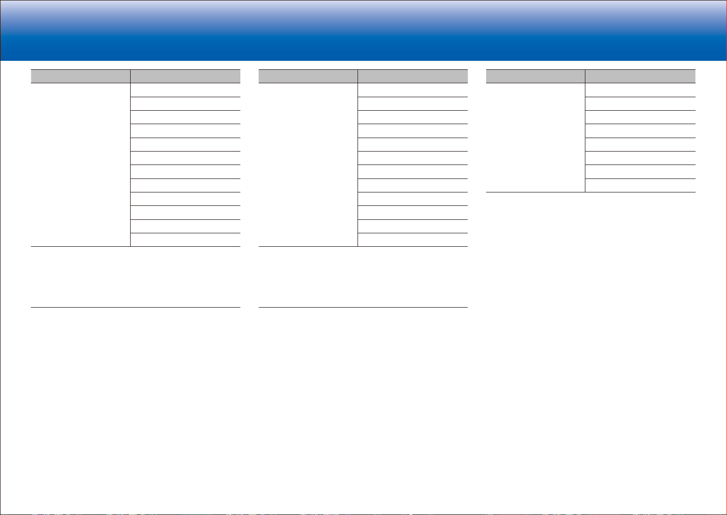
> Specifications > Settings > Listening Modes > Playback Function > Basic Manual
Troubleshooting | Appendix
Input Format Listening Mode
Multich PCM Direct
Stereo
1
Multich
Dolby Surround
2
DTS Neural:X
THX Music
THX U2 Music
Orchestra
Unplugged
Studio-Mix
AllCh Stereo
Full Mono
1
A center speaker or surround speakers need to be installed.
2
Cannot be selected when the input format is 1.1 ch or 2.1 ch.
3
Surround speakers need to be installed.
4
Surround back speakers need to be installed. Can be selected when the
input format is 5.1 ch.
5
Surround speakers or height speakers need to be installed.
6
A center speaker, surround speakers, or height speakers need to be
installed.
3
4
5
5
5
6
6
Input Format Listening Mode
DSD Direct
Stereo
1
2
DSD
Dolby Surround
DTS Neural:X
THX Music
THX U2 Music
Orchestra
Unplugged
Studio-Mix
AllCh Stereo
Full Mono
1
Cannot be selected when the input format is 2 ch.
2
A center speaker or surround speakers need to be installed.
3
Surround speakers need to be installed.
4
Surround back speakers need to be installed. Can be selected when the
input format is 5.1 ch.
5
Surround speakers or height speakers need to be installed.
6
A center speaker, surround speakers, or height speakers need to be
installed.
3
4
5
5
5
6
6
Input Format Listening Mode
Dolby Atmos
•
You can select the
Dolby Digital Plus or
Dolby TrueHD listening
modes if a surround
back speaker or
height speaker is not
connected.
Direct
Stereo
Dolby Atmos
Orchestra
Unplugged
Studio-Mix
AllCh Stereo
Full Mono
54
Page 91
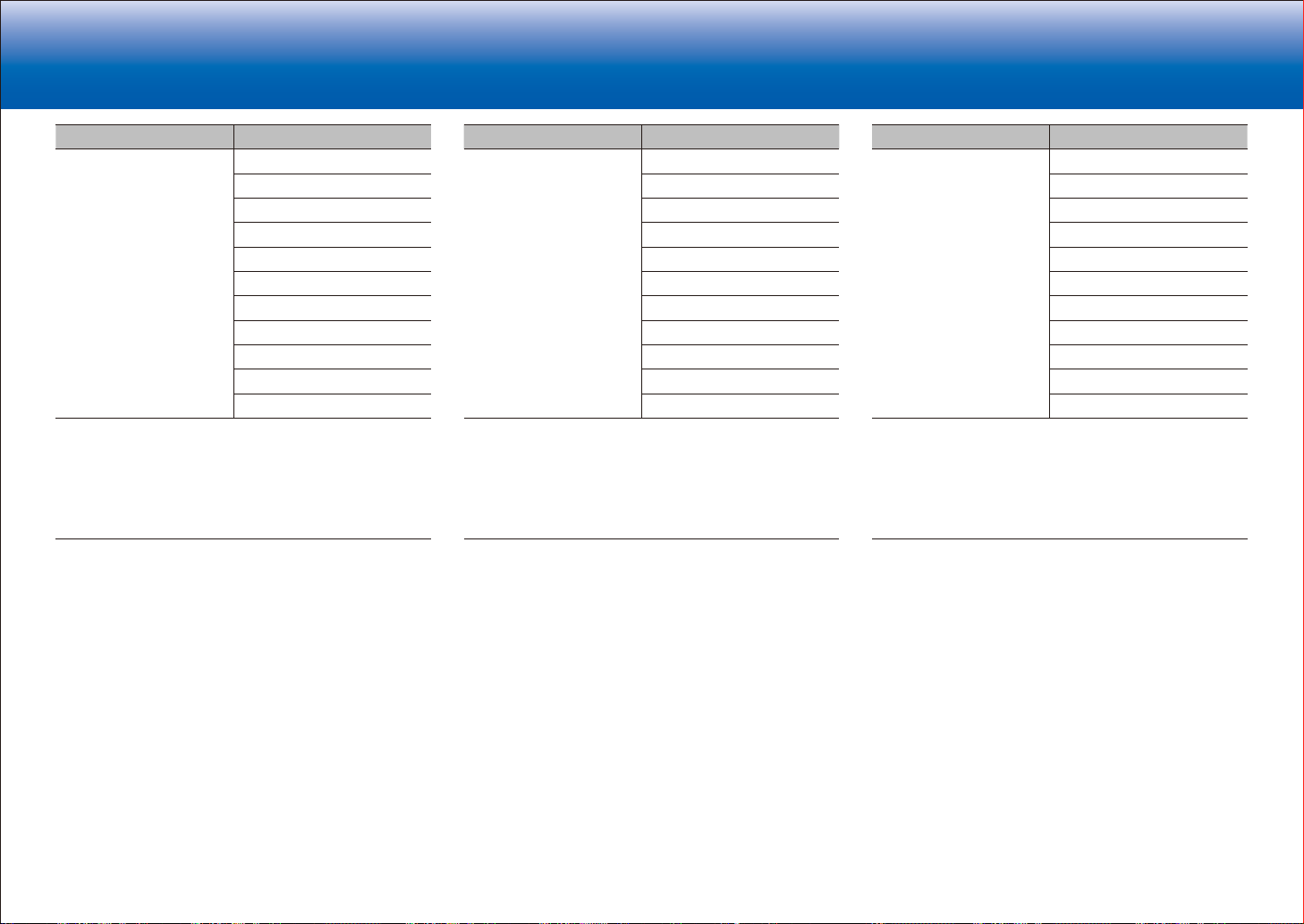
> Specifications > Settings > Listening Modes > Playback Function > Basic Manual
Troubleshooting | Appendix
Input Format Listening Mode
Dolby D Direct
Stereo
1
Dolby D
Dolby Surround
THX Music
THX U2 Music
Orchestra
Unplugged
Studio-Mix
AllCh Stereo
Full Mono
1
Cannot be selected when the input format is 2 ch.
2
A center speaker or surround speakers need to be installed.
3
Cannot be selected when the input format is 1.1 ch or 2.1 ch.
4
Surround speakers need to be installed.
5
Surround back speakers need to be installed. Can be selected when the
input format is 5.1 ch.
6
Surround speakers or height speakers need to be installed.
7
A center speaker, surround speakers, or height speakers need to be
installed.
2
3
4
5
6
6
6
7
7
Input Format Listening Mode
Dolby D+ Direct
Stereo
1
Dolby D+
Dolby Surround
THX Music
THX U2 Music
Orchestra
Unplugged
Studio-Mix
AllCh Stereo
Full Mono
1
Cannot be selected when the input format is 2 ch.
2
A center speaker or surround speakers need to be installed.
3
Cannot be selected when the input format is 1.1 ch or 2.1 ch.
4
Surround speakers need to be installed.
5
Surround back speakers need to be installed. Can be selected when the
input format is 5.1 ch.
6
Surround speakers or height speakers need to be installed.
7
A center speaker, surround speakers, or height speakers need to be
installed.
2
3
4
5
6
6
6
7
7
Input Format Listening Mode
Dolby TrueHD Direct
Stereo
1
Dolby TrueHD
Dolby Surround
THX Music
THX U2 Music
Orchestra
Unplugged
Studio-Mix
AllCh Stereo
Full Mono
1
Cannot be selected when the input format is 2 ch.
2
A center speaker or surround speakers need to be installed.
3
Cannot be selected when the input format is 1.1 ch or 2.1 ch.
4
Surround speakers need to be installed.
5
Surround back speakers need to be installed. Can be selected when the
input format is 5.1 ch.
6
Surround speakers or height speakers need to be installed.
7
A center speaker, surround speakers, or height speakers need to be
installed.
2
3
4
5
6
6
6
7
7
55
Page 92

> Specifications > Settings > Listening Modes > Playback Function > Basic Manual
Troubleshooting | Appendix
Input Format Listening Mode
DTS Direct
Stereo
1
2
DTS
DTS Neural:X
THX Music
THX U2 Music
Orchestra
Unplugged
Studio-Mix
AllCh Stereo
Full Mono
1
Cannot be selected when the input format is 2 ch.
2
A center speaker or surround speakers need to be installed.
3
Surround speakers need to be installed.
4
Surround back speakers need to be installed. Can be selected when the
input format is 5.1 ch.
5
Surround speakers or height speakers need to be installed.
6
A center speaker, surround speakers, or height speakers need to be
installed.
3
4
5
5
5
6
6
Input Format Listening Mode
DTS 96/24 Direct
Stereo
1
DTS 96/24
THX Music
THX U2 Music
Orchestra
Unplugged
Studio-Mix
AllCh Stereo
Full Mono
1
Cannot be selected when the input format is 2 ch.
2
A center speaker or surround speakers need to be installed.
3
Surround speakers need to be installed.
4
Surround back speakers need to be installed. Can be selected when the
input format is 5.1 ch.
5
Surround speakers or height speakers need to be installed.
6
A center speaker, surround speakers, or height speakers need to be
installed.
2
3
4
5
5
5
6
6
Input Format Listening Mode
DTS Express Direct
Stereo
1
DTS Express
2
DTS Neural:X
THX Music
THX U2 Music
Orchestra
Unplugged
Studio-Mix
AllCh Stereo
Full Mono
1
Cannot be selected when the input format is 2 ch.
2
A center speaker or surround speakers need to be installed.
3
Surround speakers need to be installed.
4
Surround back speakers need to be installed. Can be selected when the
input format is 5.1 ch.
5
Surround speakers or height speakers need to be installed.
6
A center speaker, surround speakers, or height speakers need to be
installed.
3
4
5
5
5
6
6
56
Page 93

> Specifications > Settings > Listening Modes > Playback Function > Basic Manual
Troubleshooting | Appendix
Input Format Listening Mode
DTS-HD HR Direct
Stereo
1
DTS-HD HR
DTS Neural:X
THX Music
THX U2 Music
Orchestra
Unplugged
Studio-Mix
AllCh Stereo
Full Mono
1
Cannot be selected when the input format is 2 ch.
2
A center speaker or surround speakers need to be installed.
3
Cannot be selected when the sampling rate of the input format is 88.2 kHz
or more.
4
Surround speakers need to be installed.
5
Surround back speakers need to be installed. Can be selected when the
input format is 5.1 ch.
6
Surround speakers or height speakers need to be installed.
7
A center speaker, surround speakers, or height speakers need to be
installed.
2
3
4
5
6
6
6
7
7
Input Format Listening Mode
DTS-HD MSTR Direct
Stereo
1
DTS-HD MSTR
DTS Neural:X
THX Music
THX U2 Music
Orchestra
Unplugged
Studio-Mix
AllCh Stereo
Full Mono
1
Cannot be selected when the input format is 2 ch.
2
A center speaker or surround speakers need to be installed.
3
Cannot be selected when the sampling rate of the input format is 88.2 kHz
or more.
4
Surround speakers need to be installed.
5
Surround back speakers need to be installed. Can be selected when the
input format is 5.1 ch.
6
Surround speakers or height speakers need to be installed.
7
A center speaker, surround speakers, or height speakers need to be
installed.
2
3
4
5
6
6
6
7
7
Input Format Listening Mode
DTS-ES Direct
Stereo
1
DTS
ES Matrix
ES Discrete
2
2
DTS Neural:X
THX Music
Orchestra
Unplugged
Studio-Mix
AllCh Stereo
Full Mono
1
This cannot be selected when surround back speakers are connected.
(When "DTS Auto Surround" in the Setup menu is set to "Off", this can be
selected.)
2
Surround back speakers need to be installed.
3
Surround speakers need to be installed.
4
Surround speakers or height speakers need to be installed.
5
A center speaker, surround speakers, or height speakers need to be
installed.
3
4
4
4
5
5
57
Page 94
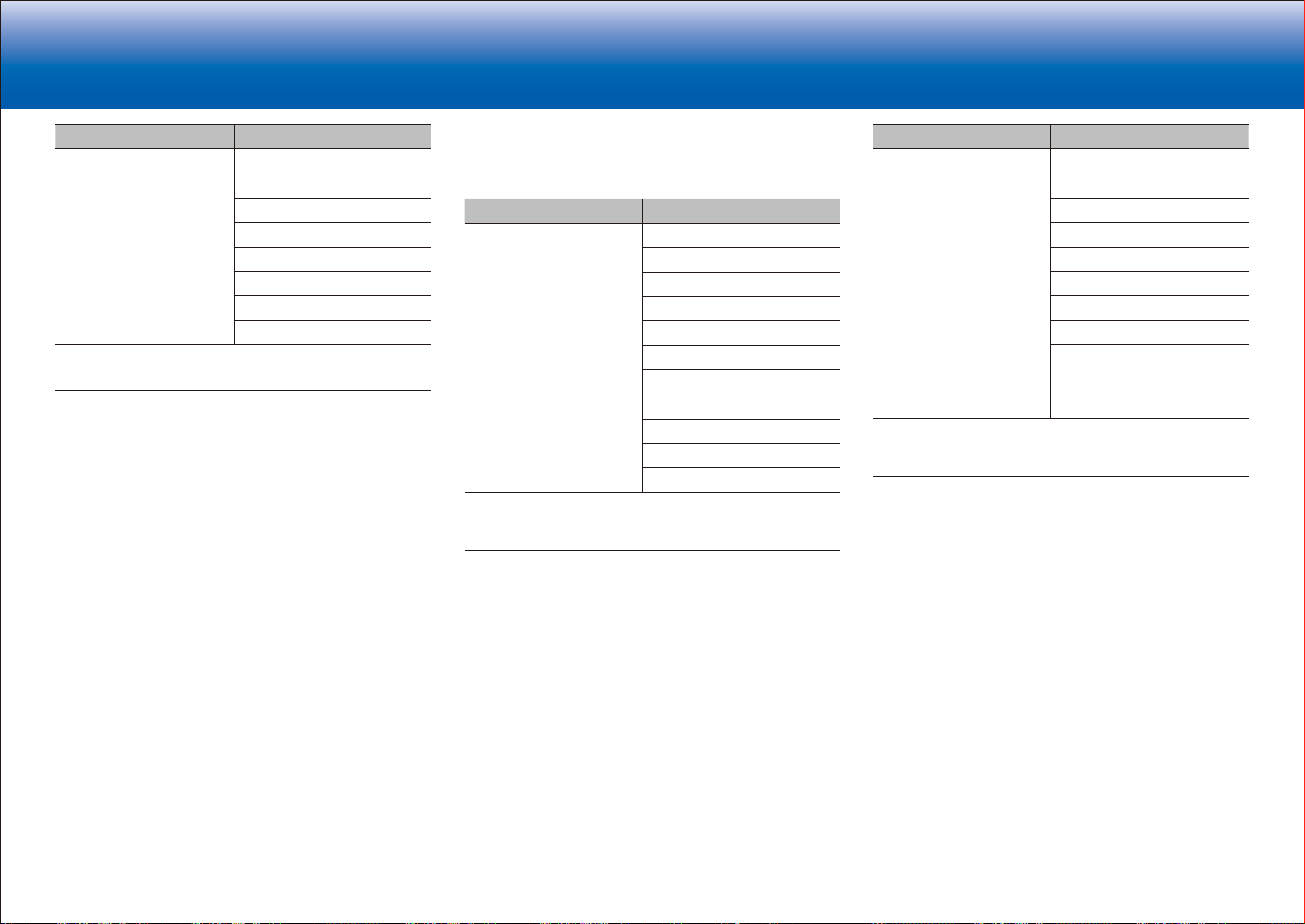
> Specifications > Settings > Listening Modes > Playback Function > Basic Manual
Troubleshooting | Appendix
Input Format Listening Mode
DTS:X Direct
Stereo
DTS:X
Orchestra
Unplugged
Studio-Mix
AllCh Stereo
Full Mono
1
Surround speakers or height speakers need to be installed.
2
A center speaker, surround speakers, or height speakers need to be
installed.
1
1
1
2
2
■ Game button
This is a list of listening modes you can select according to
the audio format of the input signal.
Input Format Listening Mode
Analog Direct
Dolby Surround
DTS Neural:X
THX Games
Game-RPG
Game-Action
Game-Rock
Game-Sports
AllCh Stereo
Full Mono
T-D
1
Surround speakers need to be installed.
2
Surround speakers or height speakers need to be installed.
3
A center speaker, surround speakers, or height speakers need to be
installed.
1
2
2
2
2
3
3
Input Format Listening Mode
PCM
Music files (except DSD/
Dolby TrueHD)
Direct
Dolby Surround
DTS Neural:X
THX Games
Game-RPG
Game-Action
Game-Rock
Game-Sports
AllCh Stereo
Full Mono
2
2
3
1
2
2
3
T-D
1
Surround speakers need to be installed.
2
Surround speakers or height speakers need to be installed.
3
A center speaker, surround speakers, or height speakers need to be
installed.
58
Page 95
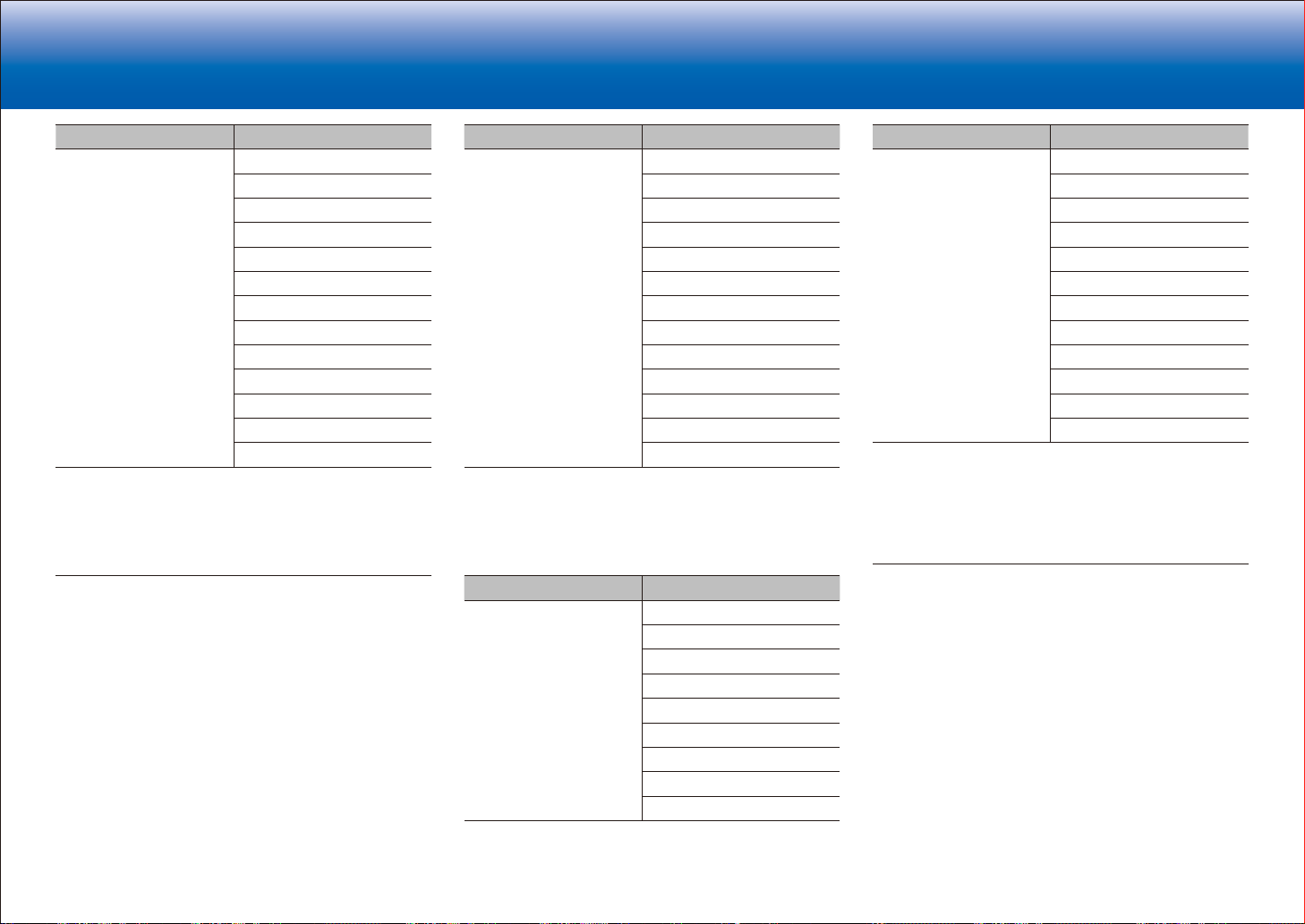
> Specifications > Settings > Listening Modes > Playback Function > Basic Manual
Troubleshooting | Appendix
Input Format Listening Mode
Multich PCM Direct
1
Multich
Dolby Surround
2
DTS Neural:X
THX Games
THX U2 Games
Game-RPG
Game-Action
Game-Rock
Game-Sports
AllCh Stereo
Full Mono
3
4
5
5
5
5
6
6
T-D
1
A center speaker or surround speakers need to be installed.
2
Cannot be selected when the input format is 1.1 ch or 2.1 ch.
3
Surround speakers need to be installed.
4
Surround back speakers need to be installed. Can be selected when the
input format is 5.1 ch.
5
Surround speakers or height speakers need to be installed.
6
A center speaker, surround speakers, or height speakers need to be
installed.
Input Format Listening Mode
DSD Direct
1
2
DSD
Dolby Surround
DTS Neural:X
THX Games
THX U2 Games
Game-RPG
Game-Action
Game-Rock
Game-Sports
AllCh Stereo
Full Mono
3
4
5
5
5
5
6
6
T-D
1
Cannot be selected when the input format is 2 ch.
2
A center speaker or surround speakers need to be installed.
3
Surround speakers need to be installed.
4
Surround back speakers need to be installed. Can be selected when the
input format is 5.1 ch.
5
Surround speakers or height speakers need to be installed.
6
A center speaker, surround speakers, or height speakers need to be
installed.
Input Format Listening Mode
Dolby Atmos
•
You can select the
Dolby Digital Plus or
Dolby TrueHD listening
modes if a surround
back speaker or
height speaker is not
connected.
Direct
Dolby Atmos
Game-RPG
Game-Action
Game-Rock
Game-Sports
AllCh Stereo
Full Mono
T-D
Input Format Listening Mode
Dolby D Direct
1
Dolby D
Dolby Surround
THX Games
THX U2 Games
Game-RPG
Game-Action
Game-Rock
Game-Sports
AllCh Stereo
Full Mono
2
3
4
5
6
6
6
6
7
7
T-D
1
Cannot be selected when the input format is 2 ch.
2
A center speaker or surround speakers need to be installed.
3
Cannot be selected when the input format is 1.1 ch or 2.1 ch.
4
Surround speakers need to be installed.
5
Surround back speakers need to be installed. Can be selected when the
input format is 5.1 ch.
6
Surround speakers or height speakers need to be installed.
7
A center speaker, surround speakers, or height speakers need to be
installed.
59
Page 96

> Specifications > Settings > Listening Modes > Playback Function > Basic Manual
Troubleshooting | Appendix
Input Format Listening Mode
Dolby D+ Direct
1
Dolby D+
Dolby Surround
THX Games
THX U2 Games
Game-RPG
Game-Action
Game-Rock
Game-Sports
AllCh Stereo
Full Mono
2
3
4
5
6
6
6
6
7
7
T-D
1
Cannot be selected when the input format is 2 ch.
2
A center speaker or surround speakers need to be installed.
3
Cannot be selected when the input format is 1.1 ch or 2.1 ch.
4
Surround speakers need to be installed.
5
Surround back speakers need to be installed. Can be selected when the
input format is 5.1 ch.
6
Surround speakers or height speakers need to be installed.
7
A center speaker, surround speakers, or height speakers need to be
installed.
Input Format Listening Mode
Dolby TrueHD Direct
1
Dolby TrueHD
Dolby Surround
THX Games
THX U2 Games
Game-RPG
Game-Action
Game-Rock
Game-Sports
AllCh Stereo
Full Mono
2
3
4
5
6
6
6
6
7
7
T-D
1
Cannot be selected when the input format is 2 ch.
2
A center speaker or surround speakers need to be installed.
3
Cannot be selected when the input format is 1.1 ch or 2.1 ch.
4
Surround speakers need to be installed.
5
Surround back speakers need to be installed. Can be selected when the
input format is 5.1 ch.
6
Surround speakers or height speakers need to be installed.
7
A center speaker, surround speakers, or height speakers need to be
installed.
Input Format Listening Mode
DTS Direct
1
2
DTS
DTS Neural:X
THX Games
THX U2 Games
Game-RPG
Game-Action
Game-Rock
Game-Sports
AllCh Stereo
Full Mono
3
4
5
5
5
5
6
6
T-D
1
Cannot be selected when the input format is 2 ch.
2
A center speaker or surround speakers need to be installed.
3
Surround speakers need to be installed.
4
Surround back speakers need to be installed. Can be selected when the
input format is 5.1 ch.
5
Surround speakers or height speakers need to be installed.
6
A center speaker, surround speakers, or height speakers need to be
installed.
60
Page 97

> Specifications > Settings > Listening Modes > Playback Function > Basic Manual
Troubleshooting | Appendix
Input Format Listening Mode
DTS 96/24 Direct
1
DTS 96/24
THX Games
THX U2 Games
Game-RPG
Game-Action
Game-Rock
Game-Sports
AllCh Stereo
Full Mono
2
3
4
5
5
5
5
6
6
T-D
1
Cannot be selected when the input format is 2 ch.
2
A center speaker or surround speakers need to be installed.
3
Surround speakers need to be installed.
4
Surround back speakers need to be installed. Can be selected when the
input format is 5.1 ch.
5
Surround speakers or height speakers need to be installed.
6
A center speaker, surround speakers, or height speakers need to be
installed.
Input Format Listening Mode
DTS Express Direct
1
DTS Express
2
DTS Neural:X
THX Games
THX U2 Games
Game-RPG
Game-Action
Game-Rock
Game-Sports
AllCh Stereo
Full Mono
3
4
5
5
5
5
6
6
T-D
1
Cannot be selected when the input format is 2 ch.
2
A center speaker or surround speakers need to be installed.
3
Surround speakers need to be installed.
4
Surround back speakers need to be installed. Can be selected when the
input format is 5.1 ch.
5
Surround speakers or height speakers need to be installed.
6
A center speaker, surround speakers, or height speakers need to be
installed.
Input Format Listening Mode
DTS-HD HR Direct
1
DTS-HD HR
DTS Neural:X
THX Games
THX U2 Games
Game-RPG
Game-Action
Game-Rock
Game-Sports
AllCh Stereo
Full Mono
2
3
4
5
6
6
6
6
7
7
T-D
1
Cannot be selected when the input format is 2 ch.
2
A center speaker or surround speakers need to be installed.
3
Cannot be selected when the sampling rate of the input format is
88.2 kHz or more.
4
Surround speakers need to be installed.
5
Surround back speakers need to be installed. Can be selected when the
input format is 5.1 ch.
6
Surround speakers or height speakers need to be installed.
7
A center speaker, surround speakers, or height speakers need to be
installed.
61
Page 98

> Specifications > Settings > Listening Modes > Playback Function > Basic Manual
Troubleshooting | Appendix
Input Format Listening Mode
DTS-HD MSTR Direct
1
DTS-HD MSTR
DTS Neural:X
THX Games
THX U2 Games
Game-RPG
Game-Action
Game-Rock
Game-Sports
AllCh Stereo
Full Mono
2
3
4
5
6
6
6
6
7
7
T-D
1
Cannot be selected when the input format is 2 ch.
2
A center speaker or surround speakers need to be installed.
3
Cannot be selected when the sampling rate of the input format is
88.2 kHz or more.
4
Surround speakers need to be installed.
5
Surround back speakers need to be installed. Can be selected when the
input format is 5.1 ch.
6
Surround speakers or height speakers need to be installed.
7
A center speaker, surround speakers, or height speakers need to be
installed.
Input Format Listening Mode
DTS-ES Direct
1
DTS
ES Matrix
ES Discrete
2
2
DTS Neural:X
THX Games
Game-RPG
Game-Action
Game-Rock
Game-Sports
AllCh Stereo
Full Mono
3
4
4
4
4
5
5
T-D
1
This cannot be selected when surround back speakers are connected.
(When "DTS Auto Surround" in the Setup menu is set to "Off", this can be
selected.)
2
Surround back speakers need to be installed.
3
Surround speakers need to be installed.
4
Surround speakers or height speakers need to be installed.
5
A center speaker, surround speakers, or height speakers need to be
installed.
Input Format Listening Mode
DTS:X Direct
DTS:X
Game-RPG
Game-Action
Game-Rock
Game-Sports
AllCh Stereo
Full Mono
1
1
1
1
2
2
T-D
1
Surround speakers or height speakers need to be installed.
2
A center speaker, surround speakers, or height speakers need to be
installed.
62
Page 99

> Specifications > Settings > Listening Modes > Playback Function > Basic Manual
Troubleshooting | Appendix
LINKS
AM/FM Radio
To return to the auto tuning mode:
Press Mode on the remote controller again so that
"TunMode:Auto" appears on the display. The unit tunes
automatically into a radio station.
Presetting a Radio Station
It allows you to register up to 40 of your favorite AM/FM
radio stations. Registering radio stations in advance allows
you to tune into your radio station of choice directly.
Tuning into a Radio Station
■ Tuning Automatically
1. Press Tuner on the remote controller several times to
select either "AM" or "FM".
2. Press Mode on the remote controller so that
"TunMode:Auto" appears on the display.
3. Press the cursors
automatic tuning.
•
Searching automatically stops when a station is
found. When tuned into a radio station, the "TUNED"
indicator on the display lights. When tuned into an
FM radio station, the "FM ST" indicator lights.
•
No sound is output while the "TUNED" indicator is
off.
When FM broadcasts reception is poor:
Radio waves may be weak depending on the building
structure and environmental conditions. In that case,
perform the procedure as explained below in "Tuning
Manually" to manually select the desired station.
/ on the remote controller to start
■ Tuning Manually
1. Press Tuner on the remote controller several times to
select either "AM" or "FM".
2. Press Mode on the remote controller so that
"TunMode:Manual" appears on the display.
3. While pressing the cursors
controller, select the desired radio station.
•
The frequency changes by 1 step each time
you press the button. The frequency changes
continuously if the button is held down and stops
when the button is released. Tune by looking at the
display.
/ on the remote
■ Registration Procedure
1. Tune into the AM/FM radio station you want to register.
2. Press Memory on the remote controller so that the
preset number on the display flashes.
3. While the preset number is flashing (about 8 seconds),
repeatedly press the cursors
controller to select a number between 1 and 40.
4. Press Memory on the remote controller again to register
the station.
•
When the station is registered, the preset number
stops flashing.
•
Repeat this procedure for all of your favorite AM/FM
radio stations.
on the remote
/
■ Selecting a Preset Radio Station
1. Press Tuner on the remote controller.
2. Press the cursors
select a preset number.
on the remote controller to
/
■ Deleting a Preset Radio Station
1. Press Tuner on the remote controller.
2. Press the cursors
select the preset number to delete.
3. After pressing Memory on the remote controller, press
Clear while the preset number is flashing to delete the
preset number.
•
When deleted, the number on the display goes off.
on the remote controller to
/
63
Page 100
> Specifications > Settings > Listening Modes > Playback Function > Basic Manual
Troubleshooting | Appendix
Using RDS (Australian and Asian models)
RDS stands for Radio Data System and is a method of
transmitting data in FM radio signals. In regions using
RDS, the radio station name is displayed when you tune
into a radio station broadcasting program information.
When you press on the remote controller in this state,
you can use the following functions.
■ Display text information (Radio Text)
1. While the name of the station is being displayed on the
display, press on the remote controller once.
Radio Text (RT) broadcast by the station is displayed
scrolling across the display. "No Text Data" is displayed
when no text information is available.
•
Unusual characters may be displayed when the unit
receives unsupported characters. However, this is not
a malfunction. Also, if the signal from a station is weak,
information may not be displayed.
■ Search for stations by Program Type
1. While the name of the station is being displayed on the
display, press on the remote controller twice.
2. Press the cursors
select the Program Type you want to find, then press
Enter to start the search.
The Program Types displayed are as follows:
None
News (News reports)
Affairs (Current affairs)
Info (Information)
Sport
Educate (Education)
Drama
Culture
Science (Science and technology)
Varied
Pop M (Pop music)
Rock M (Rock music)
Easy M (Middle of the road music)
on the remote controller to
/
64
Light M (Light classics)
Classics (Serious classics)
Other M (Other music)
Weather
Finance
Children (Children's programmes)
Social (Social affairs)
Religion
Phone In
Travel
Leisure
Jazz (Jazz music)
Country (Country music)
Nation M (National music)
Oldies (Oldies music)
Folk M (Folk music)
Document (Documentary)
•
The information displayed may sometimes not
match the content being broadcast by the station.
3. When a station is found, the station flashes on the
display. Press Enter while this is happening to start
receiving that station. If you don't press Enter, the unit
continues to search for another station.
•
If no stations are found, the message "Not Found" is
displayed.
•
Unusual characters may be displayed when the unit
receives unsupported characters. However, this is
not a malfunction. Also, if the signal from a station is
weak, information may not be displayed.
 Loading...