

Page 1

DVD Changer
DPT-1
Instruction Manual
Before Using 8
Names and Functions 9
Making Connections 15
Setting Up the Changer 20
DISC
/
CHARACTER
( Push To Enter )
Direct Custom
123
456
789
Audio / Video
Update
Play Mode Random Display Input Search
Standby
Standby/On
Text
Single Loader
Access Play
3
0
Direct Digital Path
1
D
is
c
Clear
10
PlayStop PauseOpen /Close
Keyboard / Mouse
DPT-1
Thank you for purchasing the Integra DVD
Changer.
Please read this manual thoroughly before making
connections and turning on the power.
Following the instructions in this manual will enable
you to obtain optimum performance and listening
enjoyment from your new DVD Changer.
Please retain this manual for future reference.
Getting Started Using Your DVD Changer
23
Disc Management 30
Adjusting Audio and Video Settings
39
Setting the Language Options 44
Advanced Functions 49
Additional Information 71
Page 2

Please read through these operating instructions so you will know how to operate your model properly. After you
have finished reading the instructions, put them away in a safe place for future reference.
• This changer is not suitable for commercial use.
WARNING:
TO REDUCE THE RISK OF FIRE OR ELECTRIC SHOCK,
DO NOT EXPOSE THIS APPLIANCE TO RAIN OR
MOISTURE.
CAUTION:
TO REDUCE THE RISK OF ELECTRIC SHOCK, DO NOT
REMOVE COVER (OR BACK). NO USER-SERVICEABLE
PARTS INSIDE. REFER SERVICING TO QUALIFIED
SERVICE PERSONNEL.
IMPORTANT SAFETY INSTRUCTIONS
READ INSTRUCTIONS — All the safety and
operating instructions should be read before
the product is operated.
RETAIN INSTRUCTIONS — The safety and
operating instructions should be retained for
future reference.
HEED WARNINGS — All warnings on the product
and in the operating instructions should be
adhered to.
FOLLOW INSTRUCTIONS — All operating and
use instructions should be followed.
CLEANING — Unplug this product from the wall
outlet before cleaning. The product should be
cleaned only with a polishing cloth or a soft dry
cloth. Never clean with furniture wax, benzine,
insecticides or other volatile liquids since they
may corrode the cabinet.
ATTACHMENTS — Do not use attachments not
recommended by the product manufacturer
as they may cause hazards.
WATER AND MOISTURE — Do not use this
product near water — for example, near a
bathtub, wash bowl, kitchen sink, or laundry
tub; in a wet basement; or near a swimming
pool; and the like.
ACCESSORIES — Do not place this product on
an unstable cart, stand, tripod, bracket, or
table. The product may fall, causing serious
injury to a child or adult, and serious damage
to the product. Use only with a cart, stand,
tripod, bracket, or table recommended by the
manufacturer, or sold with the product. Any
mounting of the product should follow the
manufacturer’s instructions, and should use a
mounting accessory recommended by the
manufacturer.
CART — A product and cart combination should
be moved with care. Quick stops, excessive
force, and uneven surfaces may cause the
product and cart combination to overturn.
VENTILATION — Slots and openings in the
cabinet are provided for ventilation and to
ensure reliable operation of the product and to
protect it from overheating, and these openings
must not be blocked or covered. The openings
should never be blocked by placing the product
on a bed, sofa, rug, or other similar surface.
This product should not be placed in a built-in
installation such as a bookcase or rack unless
proper ventilation is provided or the
manufacturer’s instructions have been
adhered to.
POWER SOURCES — This product should be
operated only from the type of power source
indicated on the marking label. If you are not
sure of the type of power supply to your
home, consult your product dealer or local
power company.
LOCATION – The appliance should be installed in
a stable location.
NONUSE PERIODS – The power cord of the
appliance should be unplugged from the outlet
when left unused for a long period of time.
2
WARNING
RISK OF ELECTRIC SHOCK
DO NOT OPEN
The lightning flash with arrowhead symbol, within an equilateral
triangle, is intended to alert the user to the presence of uninsulated
“dangerous voltage” within the product’s enclosure that may be of
sufficient magnitude to constitute a risk of electric shock to persons.
The exclamation point within an equilateral triangle is intended to
alert the user to the presence of important operating and maintenance
(servicing) instructions in the literature accompanying the appliance.
GROUNDING OR POLARIZATION
• If this product is equipped with a polarized
alternating current line plug (a plug having one
blade wider than the other), it will fit into the
outlet only one way. This is a safety feature. If
you are unable to insert the plug fully into the
outlet, try reversing the plug. If the plug should
still fail to fit, contact your electrician to replace
your obsolete outlet. Do not defeat the safety
purpose of the polarized plug.
• If this product is equipped with a three-wire
grounding type plug, a plug having a third
(grounding) pin, it will only fit into a grounding
type power outlet. This is a safety feature. If
you are unable to insert the plug into the
outlet, contact your electrician to replace your
obsolete outlet. Do not defeat the safety
purpose of the grounding type plug.
POWER-CORD PROTECTION — Power-supply
cords should be routed so that they are not
likely to be walked on or pinched by items
placed upon or against them, paying particular
attention to cords at plugs, convenience
receptacles, and the point where they exit
from the product.
OUTDOOR ANTENNA GROUNDING — If an
outside antenna or cable system is connected
to the product, be sure the antenna or cable
system is grounded so as to provide some
protection against voltage surges and built-up
static charges. Article 810 of the National
Electrical Code, ANSI/NFPA 70, provides
information with regard to proper grounding of
the mast and supporting structure, grounding
of the lead-in wire to an antenna discharge
unit, size of grounding conductors, location of
antenna-discharge unit, connection to
grounding electrodes, and requirements for
the grounding electrode. See Figure A.
LIGHTNING — For added protection for this
product during a lightning storm, or when it is
left unattended and unused for long periods of
time, unplug it from the wall outlet and
disconnect the antenna or cable system. This
will prevent damage to the product due to
lightning and power-line surges.
POWER LINES — An outside antenna system
should not be located in the vicinity of overhead
power lines or other electric light or power
circuits, or where it can fall into such power
lines or circuits. When installing an outside
antenna system, extreme care should be taken
to keep from touching such power lines or
circuits as contact with them might be fatal.
OVERLOADING — Do not overload wall outlets,
extension cords, or integral convenience
receptacles as this can result in a risk of fire or
electric shock.
ELECTRIC
SERVICE
EQUIPMENT
AVIS
RISQUE DE CHOC ELECTRIQUE
OBJECT AND LIQUID ENTRY — Never push
objects of any kind into this product through
openings as they may touch dangerous voltage
points or short-out parts that could result in a
fire or electric shock. Never spill liquid of any
kind on the product.
SERVICING — Do not attempt to service this
product yourself as opening or removing
covers may expose you to dangerous voltage
or other hazards. Refer all servicing to qualified
service personnel.
DAMAGE REQUIRING SERVICE — Unplug this
product from the wall outlet and refer servicing
to qualified service personnel under the
following conditions:
• When the power-supply cord or plug is
damaged.
• If liquid has been spilled, or objects have fallen
into the product.
• If the product has been exposed to rain or
water.
• If the product does not operate normally by
following the operating instructions. Adjust
only those controls that are covered by the
operating instructions as an improper
adjustment of other controls may result in
damage and will often require extensive work
by a qualified technician to restore the product
to its normal operation.
• If the product has been dropped or damaged
in any way.
• When the product exhibits a distinct change in
performance — this indicates a need for
service.
REPLACEMENT PARTS — When replacement
parts are required, be sure the service
technician has used replacement parts
specified by the manufacturer or have the
same characteristics as the original part.
Unauthorized substitutions may result in fire,
electric shock, or other hazards.
SAFETY CHECK — Upon completion of any
service or repairs to this product, ask the
service technician to perform safety checks to
determine that the product is in proper
operating condition.
WALL OR CEILING MOUNTING — The product
should not be mounted to a wall or ceiling.
HEAT — The product should be situated away
from heat sources such as radiators, heat
registers, stoves, or other products (including
amplifiers) that produce heat.
GROUND
CLAMP
Fig. A
POWER SERVICE GROUNDING
ELECTRODE SYSTEM
(NEC ART 250, PART H)
NEC — NATIONAL ELECTRICAL CODE
OUVRIR
NE PAS
ANTENNA
LEAD IN WIRE
ANTENNA
DISCHARGE UNIT
(NEC SECTION 810-20)
GROUNDING CONDUCTORS
(NEC SECTION 810-21)
GROUND CLAMPS
Page 3

CONGRATULATIONS ON YOUR PURCHASE OF
THIS FINE Integra PRODUCT.
Integra is on the leading edge of DVD research for
consumer products and this unit incorporates the latest
technological developments.
We are sure you will be fully satisfied with the DVD
changer.
Thank you for your support.
WARNING: TO PREVENT FIRE OR SHOCK HAZARD, DO
NOT EXPOSE THIS APPLIANCE TO RAIN OR
MOISTURE.
IMPORTANT NOTICE
[For U.S. and Canadian models]
The serial number for this equipment is located on the
rear panel. Please write this serial number on your
enclosed warranty card and keep it in a secure area. This
is for your security.
CAUTION: This product satisfies FCC regulations when
shielded cables and connectors are used to connect
the unit to other equipment. To prevent
electromagnetic interference with electric appliances
such as radios and televisions, use shielded cables
and connectors for connections.
This equipment has been tested and found to comply
with the limits for a Class B digital device, pursuant to
Part 15 of the FCC Rules. These limits are designed
to provide reasonable protection against harmful
interference in a residential installation. This
equipment generates, uses, and can radiate radio
frequency energy and, if not installed and used in
accordance with the instructions, may cause harmful
interference to radio communications. However,
there is no guarantee that interference will not occur
in a particular installation. If this equipment does
cause harmful interference to radio or television
reception, which can be determined by turning the
equipment off and on, the user is encouraged to try
to correct the interference by one or more of the
following measures:
– Reorient or relocate the receiving antenna.
– Increase the separation between the equipment and
receiver.
– Connect the equipment into an outlet on a circuit
different from that to which the receiver is
connected.
– Consult the dealer or an experienced radio/TV
technician for help.
CAUTION
• Use of controls or adjustments or performance of
procedures other than those specified herein may
result in hazardous radiation exposure.
• The use of optical instruments with this product
will increase eye hazard.
[For Canadian model]
This Class B digital apparatus complies with Canadian
ICES-003
[Pour le modèle Canadien]
Cet appareil numérique de la classe B est conforme à
la norme NMB-003 du Canada.
[For Canadian model]
CAUTION: TO PREVENT ELECTRIC SHOCK, DO NOT
USE THIS (POLARIZED) PLUG WITH AN EXTENSION
CORD, RECEPTACLE OR OTHER OUTLET UNLESS THE
BLADES CAN BE FULLY INSERTED TO PREVENT
BLADE EXPOSURE.
ATTENTION: POUR PREVENIR LES CHOCS
ELECTRIQUES NE PAS UTILISER CETTE FICHE
POLARISEE AVEC UN PROLONGATEUR, UNE PRISE
DE COURANT OU UNE AUTRE SORTIE DE COURANT,
SAUF SI LES LAMES PEUVENT ETRE INSEREES A
FOND SANS EN LAISSER AUCUNE PARTIE A
DECOUVERT.
This product incorporates copyright protection
technology that is protected by method claims of
certain U.S. patents and other intellectual property
rights owned by Macrovision Corporation and other
rights owners. Use of this copyright protection
technology must be authorized by Macrovision
Corporation, and is intended for home and other
limited viewing uses only unless otherwise
authorized by Macrovision Corporation. Reverse
engineering or disassembly is prohibited.
Information to User
Alteration or modifications carried out without
appropriate authorization may invalidate the user's
right to operate the equipment.
3
Page 4

Features of This Changer
301 capacity disc changer
compatible with DVD Video,
Video CD, CD, and CD-R formats
DVDs, Video CDs, CDs, and CD-Rs that display the
logos shown below can be played back on Integra DVD
players. For more information on discs compatible with
this changer, refer to the table below.
Types of playable
discs and their marks
DVD VIDEO DVD VIDEO
VIDEO CD
CD, CD TEXT, CD-R
Diameter/
Playable sides
12 cm (5 in.)/
single-sided
12 cm (5 in.)/
double-sided
VIDEO CD
12 cm (5 in.)/
single-sided
VIDEO CD single
8 cm (3 in.)/
single-sided
CD
12 cm (5 in.)/
single-sided
1 layer
2 layer
1 layer
2 layer
Playback time
Digital audio
Digital video
(MPEG 2)
133 min.
242 min.
266 min.
484 min.
Digital audio
Digital video
(MPEG 1)
Max. 74
minutes
Digital audio
Digital video
(MPEG 1)
Max. 20
minutes
Digital audio
Max. 74
minutes
State of the art digital audio and
video
Compatible with a wide range of digital audio
output formats
The digital audio output jacks of this changer can output
Dolby Digital*, DTS**, MPEG, and linear PCM digital
bitstreams to AV components with built-in decoding
capabilities.
Multiple video output formats that can be
selected to best suit your TV or monitor
This changer features composite, S-video, and
component jacks to offer ideal connection possibilities to
nearly every type and level of commercially available TV
or monitor on the market today.
Digital Noise Reduction (Video Quality
Enhancement)
DNR (Digital Noise Reduction) can be used to improve
the video image and remove digital noise. Select a
preprogrammed setting suited to the program’s subject
matter, or make manual adjustments to suit your needs
or preferences and save them in the changer’s memory.
* Manufactured under license from Dolby Laboratorles.
“Dolby” and the double-D symbol are trademarks of Dolby
Laboratories, Confidential unpublished works,
Dolby Laboratories, All rights reserved.
** “DTS” is a trademark of Digital Theater Systems, Inc.
Manufactured under license from Digital Theater Systems,
Inc.
1992-1997
CD single
8 cm (3 in.)/
*
single-sided
The disc format logos shown above are found on disc
labels or on disc jackets.
• To prevent malfunction, be sure to use an adapter
when loading 8 cm (3 in.) CDs in the changer.
• To prevent malfunction, do not use 8 cm (3 in.) CD
adapters with 8 cm (3 in.) DVDs.
• Discs other than the ones indicated above cannot be
played on this unit.
• DVDs that have incompatible region numbers cannot
be played on this unit. The region number of the
changer can be found on the rear panel.
* This unit is capable of playing prerecorded audio CD-R discs.
• Due to variances in recording processes and disc types as
well as minor scratches, dust, fingerprints, or condensation
on the disc or pickup lens, playback may not be possible
with some discs.
• If a CD-R disc has not undergone a process called
finalization, playback is possible, however other functions
such as fast forward and reverse scanning, and track
search cannot be performed.
• Be sure to read the guidelines for using an audio CD-R disc
4
in the documentation supplied with the CD-R disc.
Digital audio
Max. 20
minutes
Page 5

New graphical control and disc
management
It has never been easier to manage 300 discs than with
this changer’s on-screen graphical control screens. Using
the changer’s Sub Setup screen, you can input titles and
artists for the discs loaded in the changer, sort them
according to number, disc type, title, or artist, organize
them into groups, and keep the information updated
even if you physically reorganize the discs (page 30).
Auto UpdateCustom
Organize all of the discs in
the rack by inputting disc
titles and artist names for
easy search and reference.
Text
Title
Type
Disc
1 DVD Silver Skies Matt Jones
2 DVD Someone2Hold S. Benak
3 VCD Dance Coll. Various
4 DVD
5 CD Live at Roxy! Exhibition
4 ¢
Page
Item
PLAY
ENTER
Play
Input
Artist
SUB SETUP
Exit
Easy text input
This title of a disc and the artist name can be easily input
using the remote controller or the front panel.
Additionally, you can connect a commercially available
PS/2* compatible keyboard or mouse to this changer for
quicker and more efficient data input and other changer
functions (page 33).
/
CHARACTER
DISC
( Push To Enter )
Direct Custom
123
456
789
Update
Audio / Video
Play Mode Random Display Input Search
Text
Standby
Single Loader
Standby/On
Access Play
3
0
1
isc
D
Direct Digital Path
* PS/2 is a registered trademark of IBM corporation.
Clear
10
PlayStop PauseOpen /Close
Keyboard / Mouse
DPT-1
Connection to another disc
changer for increased capacity
This unit can be connected to another DPT-1 unit for
combined control of up to 601 discs (page 66).
/
Play Mode Random Display Input Search
Standby
Standby/On
CHARACTER
DISC
( Push To Enter )
Direct Custom
123
456
789
Audio / Video
Update
Clear
Text
Single Loader
Access Play
10
3
0
1
is
D
c
Direct Digital Path
PlayStop PauseOpen /Close
Keyboard / Mouse
Play Mode Random Display Input Search
Text
Standby
Single Loader
Standby/On
Access Play
3
0
1
is
D
c
DPT-1
Direct Digital Path
Direct Custom
123
456
789
Audio / Video
10
/
CHARACTER
DISC
( Push To Enter )
Update
Clear
PlayStop PauseOpen /Close
Keyboard / Mouse
DPT-1
Easy setup and adjustment using
on-screen menus
You’ll find setting up and adjusting the system easy to
do with on-screen menus conveniently organized and
arranged. Additionally, on-screen information (i)
appears to clarify the functions and explain the options
available.
Answer a few questions and
have all the necessary audio,
video, and on-screen
language adjustments set
automatically by the changer
using the Setup Navigator
(page 20).
Audio1 GeneralLanguageVideo2
Setup Navigator
Setup Navigator
Setting up using the Setup Navigator
Move
ENTER
Start
Not Used
Select
SETUP
Exit
Additionally, you can create a list of menu items that you
regularly use with the Function Memory so that they can
be easily accessed at any time (page 63).
Variable speed scanning in
forward and reverse directions
This changer incorporates technology that enables
playback of DVDs and Video CDs in forward and reverse
directions using MULTI DIAL on the remote controller
(page 53).
Wide range of DVD viewing options
Multi-Language Subtitles (page 44)*
You can select a subtitle language or turn subtitles off
when watching movies or other media with subtitles
available.
Multiple Languages (page 45)*
You can select the language when watching movies or
other media that have multiple language and/or audio
soundtracks recorded on them.
Multi-Angle (page 54)*
You can view scenes from different camera angles when
watching movies or other media with multiple angle
playback available.
* This mark indicates this may not be possible with certain discs.
Energy-saving design
This unit is designed to use less than 0.9 W of energy
when this changer is in standby mode.
Quick and easy playback with
single loader slot
By using the single loader slot, you can quickly load
discs, such as rental DVDs, that you may not want to
have loaded in the disc rack all of the time. With the
touch of a single button, this disc can be called up and
played at any time (page 28).
5
Page 6

Differences in Disc
How to Proceed in This
Composition
DVD
DVDs are divided into units referred to as titles, and
titles are divided into chapters. A DVD which contains a
movie may have only one title with many or no chapter
divisions. Karaoke DVDs may have many titles, assigning
a title to each song on the DVD. Menu screens do not
belong to any title.
DVD player functions generally apply to titles on a DVD
or chapters within a selected title. The player functions
available may also vary from title to title, depending on
the DVD. When DVDs have a unique title division, it
should be noted that search and program functions may
be affected.
Chapter 1 Chapter 2
Title 1
Chapter 1
DVD
Video CD/CD
Video CDs and CDs are divided into units referred to as
tracks (Video CD tracks may also be referred to as
scenes). One song generally corresponds to one track.
Some tracks are further divided into units referred to as
indexes. Video CDs with PBC (Playback Control) also
contain menus recorded on the disc which enable easy
access to the contents of the disc.
When played back on a DVD player, both Video CDs and
CDs are considered to be a single title, regardless of the
number of tracks.
Track 1 Track 2 Track 3 Track 4
Video CD
Title 2
Chapter 2
Manual
DVD is an incredible format that presents the highest
quality digital audio and video available today. Because
using the DVD changer and DVDs may be confusing at
first, following the order below should help you get
through the important stages of getting set up so you
can start using your changer as soon as possible.
Get familiar with the changer.
Refer to the section “Before Using” on page 8 to
confirm that all the accessories were included with the
changer. If you are new to DVD, it might be beneficial for
you to go through the “Names and Functions” section
starting on page 9 to get familiar with the parts and
buttons on the main unit and remote controller.
There is also a list of terms that can be found on page 76
if you are having trouble understanding some of the
terminology associated with DVD.
Make the necessary connections.
No entertainment system seems to be set up exactly
the same way. The “Making Connections” section
starting on page 15 shows how video and audio
connections may be made to suit your home
entertainment system.
Set up the changer.
Before you can begin to enjoy the benefits of the DVD
format, it is first necessary to set up the changer to
output the video and audio corresponding to your
system. The section “Setting Up the Changer” starting
on page 20 explains how to use the Setup Navigator, a
function that automatically sets up your changer. The
Setup screen menus, described in the section starting
on page 39, are also used in a number of other
functions. Learning the procedure for operating these
menus will make using this changer much easier and
more enjoyable.
Load the disc rack and play discs.
When all the connections and setups have been made,
you are ready to play your DVDs, Video CDs, and CDs
with the changer. The section “Getting Started Using
Your DVD Changer” starting on page 23 outlines the
basic changer operations.
Organize the discs in the disc rack.
Track 2 Track 4Track 3Track 1 Track 5
CD
The section “Disc Management” on page 30 helps you
manage the discs you have loaded in the rack by making
use of the Sub Setup screen menus. By taking advantage
of this changer’s text input and cross-referencing
capabilities, it is quick and easy to find the disc you want.
Enjoy the other features available.
Once you are comfortable using the basic changer
functions, you are ready to take advantage of the various
options DVD and this changer have to offer. The section
6
“Advanced Functions” starting on page 49 describes a
number of functions available with this changer.
Page 7

Table of Contents
Before Using ........................................ 8
Checking Accessories ..................................... 8
Preparing the Remote Controller .....................8
Names and Functions ......................... 9
Front Panel ...................................................... 9
Display Window............................................. 10
Remote Controller .........................................12
Rear Panel ..................................................... 14
Making Connections ......................... 15
Connecting Your DVD Changer ......................15
Audio Connections ........................................ 17
Video Connections......................................... 18
Setting Up the Changer.................... 20
Using the Setup Navigator............................. 20
Getting Started Using Your DVD
Changer .............................................. 23
Loading DVDs, Video CDs and CDs
into the Changer ...................................... 23
Playing DVDs, Video CDs and CDs................ 24
Chapter (Track) Skip Forward/Skip Back ........ 27
Forward and Reverse Scanning .....................27
Playing a Disc That Is Not Loaded in the Rack
(Single Loader Play).................................. 28
Stopping Playback and Switching Power Off .. 29
Disc Management ............................. 30
Registering Information and Inputting Text
for Discs Newly Loaded in the Changer .. 30
Keeping the Disc Order and Information
Updated ................................................... 31
Inputting and Changing Text Information ...... 31
Selecting a Disc On-Screen ...........................35
Searching for a Disc, Title, Chapter, Track, or
Location on a Disc.................................... 35
Creating and selecting custom files .............. 37
Adjusting Audio and Video
Settings .............................................. 39
Using the Setup Screen Menus .................... 39
Changing to the Setup Screen “Expert”
Menu Mode .............................................40
Setting the Digital Audio Output To Be
Compatible with Your AV Component......41
Turning the Digital Output On and Off ...........42
Adjusting the OSD (On-Screen Display) ........ 42
Setting the TV Screen Size ............................43
Setting the Language Options......... 44
Selecting a Subtitle Language
(Multi-Language Subtitles) .......................44
Changing the Audio Language
(Multi-Language Function) ....................... 45
Setting Language and Subtitle Preferences
in the Setup Screen Menus .....................46
Advanced Functions ......................... 49
Getting Surround Sound from
Stereo Speakers....................................... 49
Adjusting the Dynamic Range of the
Audio Soundtrack ..................................... 49
Adjusting the Video Quality
(Digital Noise Reduction).......................... 50
Still Frame/Slow Play/Frame
Advance Playback ....................................52
Scanning in Forward and Reverse
Directions at Different Speeds................. 53
Viewing from a Desired Camera Angle
(Multi-Angle)............................................. 54
Repeat Play.................................................... 55
Random Play.................................................. 56
Playback in a Desired Order (Program Play) .... 57
To make an ongoing program of your favorite
titles, chapters and tracks (Best play) ...... 59
Reviewing Previously Played Discs
(Previous Scan) ........................................ 60
Previewing Discs in the Current Play Mode
(Hi-Lite Scan) ............................................ 60
Continuing Playback from a Specified
Location (Last Memory) ...........................61
Memorizing Settings for Often Viewed
DVDs (Condition Memory) .......................62
Memorizing Regularly Used Menu Settings
(Function Memory)................................... 63
Viewing Disc Information .............................. 64
Connecting to Another Changer for Control
of 601 Discs .............................................66
Utilizing the Audio-Video Output of
Another AV Component ...........................68
Selecting External Input................................. 68
Setting the Parental Lock Level .....................69
Turning the Screen Saver On and Off ............70
Changing the Background Color
of the Screen ........................................... 70
Additional Information ..................... 71
Disc Care ....................................................... 71
For Proper and Long Use of This Unit ........... 72
Language Code List .......................................73
Troubleshooting ............................................. 74
Resetting the Changer to System Settings ...75
Terms .............................................................76
Specifications ................................................78
7
Page 8

Before Using
Checking Accessories
Please confirm that the following were received with the
changer.
Audio cord
Preparing the Remote Controller
Inserting batteries into the remote
controller
1 Push down on the tab on the battery
compartment cover, and pull out in the
direction indicated by the arrow.
Video cord
Master-Slave control cord
Remote controller
AA/R6P batteries
AC cord
Remote control operation
P
L
A
Y
M
O
D
E
R
A
N
D
O
M
D
I
S
P
L
A
Y
I
N
P
U
T
S
E
A
R
C
S
H
T
A
N
D
B
Y
T
E
X
T
S
T
A
N
D
B
Y
/
O
N
S
I
N
G
L
E
A
C
L
O
C
E
A
S
D
S
E
R
P
L
A
Y
3
0
1
D
i
s
c
D
i
r
e
c
t
D
i
g
i
t
a
l
P
a
t
h
5 m
30¡
(16 ft.)
30¡
2 Insert batteries.
Make sure to match the plus (+) and minus
(–) polarity guides on the batteries with the marks
inside the battery compartment.
3 Close the cover.
Notes
• Do not mix old and new batteries.
• When replacing batteries, use all new batteries.
• When not using the remote controller for a long period of time
(over 1 month), remove the batteries to avoid possible damage
from battery corrosion. If battery leakage occurs, wipe the
battery liquid from the battery component, then insert new
batteries.
When operating the remote controller, point it at the remote
sensor located on the changer’s front panel. The remote
controller can be used up to 5 m (16 feet) from the changer
and within a 30° angle on each side of the sensor.
Notes
D
I
R
E
C
T
C
U
S
T
O
M
1
D
I
S
C
/
C
H
A
(
2
R
P
A
U
C
S
T
H
E
T
R
O
E
N
T
3
E
R
)
4
5
6
7
8
9
A
U
D
I
O
/
V
I
D
E
O
U
1
P
0
D
A
T
E
C
L
E
A
R
O
P
E
N
/
C
L
O
S
E
S
T
O
P
P
L
A
Y
P
A
U
S
E
K
E
Y
B
O
A
R
D
/
M
O
U
S
E
D
PT-1
• Exposing the remote sensor to direct sunlight or strong light
may cause faulty operation.
• When Master-Slave connections are made to another DPT-1 to
create a 601-disc changer, only the remote sensor on the first
DPT-1 will accept signals from the remote controller
(page 66).
8
Page 9

Names and
Functions
Front Panel
1 2 3 479 0 -8
Play Mode Random Display Input Search
Standby
Standby/On
5
Text
Single Loader
Access Play
%^&*()
1 Play Mode button
Press repeatedly to select one of the changer’s play
modes. You can select either single play, ALL play,
or custom play (page 26).
6
301 Disc
Direct Digital Path
Direct Custom
123
456
789
Audio / Video
Update
10
Keyboard / Mouse
$
7 Direct Custom buttons
Number buttons
Press the number button of the custom file you
want to play. Playback of the discs in the selected
custom file begins automatically (page 38).
2 Display window
Displays system information (page 10).
Audio/Video button
Press repeatedly to select the audio or video custom
file bank (page 38).
3 Text Display button
Press repeatedly to display the disc title or artist
name in the display window. When text information
is included on the disc, this information will also be
displayed.
4 Text Input button
Press to start text input (page 33).
5 Text Search button
Press to search for a disc loaded in the rack by
format, disc title, or artist (page 36).
6 Hood
The hood can be opened and closed by pressing
Open/Close (page 23).
8 Update button
Use to update information on the discs loaded in the
rack (pages 30 and 31).
9 Selection dial
Rotate to select a disc number. When inputting text,
rotate to select a character (pages 23, 26, and 33).
Press to select the disc or enter text that has been
selected using the selection dial (pages 26 and 32).
0 4 1 (reverse) button
Press to go back to previous chapters/tracks. Press
and hold to perform reverse playback scanning. When
using the front panel to edit input text, use to move
the position of the cursor (pages 27 and 33).
Disc/
Character
( Push To Enter )
Clear
PlayStop PauseOpen /Close
DPT-1
~!
=# @
BEFORE USING / NAMES AND FUNCTIONS
9
Page 10

- ¡ ¢ (forward) button
Press to advance to chapters/tracks. Press and hold
to perform fast-forward scanning. When using the
front panel to edit input text, use to move the position of
the cursor (pages 27 and 33).
= Clear button
Use to cancel repeat and random playback, edit
programs, and clear text entries (pages 33, 55, 56, 58,
and 62).
~ 8 (pause) button
Press during playback to pause. Press again to
continue playback (page 52).
$ Open/Close button
Press to open and close the hood (pages 23 and 24).
% Single Loader Play button
Press to play the disc loaded in the single loader slot.
This button can be used at any time, even if another
disc is being played (page 28).
^ Single Loader Access button
Press to have the hood open and the single loader
slot brought to the front position (page 28).
& Random button
Press to start random playback (page 56).
! 3 (play) button
Press to start disc playback (pages 24 and 29).
@ 7 (stop) button
Press to stop playback (page 29).
# Keyboard/Mouse connection jack
A PS/2 compatible keyboard or mouse can be
connected to this jack for easy entry and editing of
text information (page 33 and 34).
Display Window
1 2 3 64 5 7
VIDEO CD
CD
DOLBY
DVD
DIGITAL
#*
TITLEDISC
PBC PLAY
96 kHz
* Remote sensor
Point the remote controller toward the remote
sensor to operate the changer (page 8).
( Standby/On button
Press to switch the changer on or to put in standby
(pages 20, 23, 29, and 75).
) Standby indicator
Indicates that the changer is in standby, using a
minimum amount of power to maintain system
settings (page 29).
TRK
REMAIN
CHP
CD TEXT ANGLE
PREVIOUS SCAN
BEST PROGRAM
RANDOM REPEAT
COND. MEMORY
LAST MEMORY
TOTAL
SINGLE
CUSTOM
AUDIO
VIDEO
ALL
GUI
1 Character display
Displays text information already recorded on the
disc such as CD TEXT or DVD text, and also text
manually input into the changer.
2 VIDEO CD indicator
Indicates a Video CD is currently selected in the
10
changer.
¢
™¡ + _ )
*
&
^
%
$
(£
CD TEXT ANGLE
PREVIOUS SCAN
BEST PROGRAM
RANDOM REPEAT
COND. MEMORY
LAST MEMORY
3 DISC indicator
Indicates the disc number.
4 TITLE indicator
Indicates a title number is being displayed.
890-
=
~
!
@
#
Page 11

5 TRK and CHP indicators
Indicates a chapter or track number is being
displayed.
6 REMAIN and TOTAL indicators
REMAIN indicates the remaining playback time of a
title or chapter/track is being displayed. TOTAL
indicates the disc in the changer is stopped and
DISPLAY has been pressed (page 65).
% RANDOM indicator
Indicates random playback is being performed (page 56).
^ BEST indicator
Indicates Best play is being performed (page 59).
& PREVIOUS SCAN indicator
Indicates Previous scan is being performed (page 60).
7 Counter display
Displays title and chapter/track numbers, playback
time, etc.
8 GUI indicator
Indicates an on-screen menu operation is being
performed.
9 Custom file indicator
Indicates the number of the currently selected
custom audio or video file (pages 26 and 38).
0 AUDIO and VIDEO indicators
During custom play, indicate whether the current
custom file is an audio (CD) or video (DVD or Video
CD) custom file (pages 26 and 38).
- ALL, SINGLE, and CUSTOM indicators
Indicates the current play mode (page 26).
= ANGLE indicator
Indicates Multi-Angle playback is in progress
(page 54).
~ SCAN indicator
Indicates a Hi-Lite scan is being performed (page 60).
! PROGRAM indicator
Indicates program playback is being performed
(page 57).
* CD TEXT indicator
Indicates the CD is recorded with CD TEXT
information. When a DVD recorded with text is
encountered, only the TEXT indicator lights.
( 96 kHz indicator
Indicates the DVD currently playing contains an
audio signal with a sampling frequency of 96 kHz.
) PBC PLAY indicator
Indicates PBC (playback control) playback of a Video
CD.
_ DOLBY DIGITAL indicator
Indicates Dolby Digital audio playback.
+ DTS indicator
Indicates DTS audio playback.
¡ * (pause) indicator
Indicates playback is paused.
™ # (play) indicator
Indicates a disc is playing.
£ DVD indicator
Indicates a DVD is currently selected in the changer.
¢ CD indicator
Indicates a CD is currently selected in the changer.
NAMES AND FUNCTIONS
@ REPEAT indicator
Indicates repeat playback is being performed (page 55).
# LAST MEMORY indicator
Indicates the Last Memory location is registered in
memory for the DVD currently playing (page 61).
$ COND. MEMORY indicator
Indicates Condition Memory settings are memorized
for the DVD currently playing (page 62).
11
Page 12

Remote Controller
All of the command buttons on the remote controller glow
in the dark for easy control of the changer even in the dark.
Hold the unit under a light for optimal results.
1
2
3
4
5
6
OPEN/
POWER
CLOSE
DISPLAY AUDIO SUBTITLE ANGLE
MENU
MULTI DIAL
ENTER
TOP MENU
+
SETUP
STUP T.MNU
-
&
*
(
)
_
4 DISPLAY button
Press during playback to display statistical disc
information. Press repeatedly to display different
information (page 64).
5 SETUP button*
Press to open and close the Setup screen (pages 20
and 39).
6 MULTI DIAL
In Select Disc Number Mode, use to select one of
the discs in the rack. In Jog Mode, use to control the
rate and direction of playback (pages 23, 26, and 53).
7 DNR button
Press DNR to select a preprogrammed picture
quality setting or to adjust various attributes of the
video picture (page 51).
7
8
9
0
=
~
!
@
#
$
%
^
FUNCTION
MEMORY
F.M EM
STOP PLAY PAUSE
RETURN STEP
1
45
78
RANDOM REPEAT
SUB
SETUP
HI-LITE
SELECT
DISC No.
DISC
/
SLOW
3C
2
6
9
-
A
LAST
CONDITION
MEMORY
MEMORY
PREVIOUS
BEST
SCAN
REMOTE CONTROLLER
-
416
DV
RC
SEARCH MODE
BRPTRDM PGM
JOG MODE
JOGDNR
CLEAR
+10
0
PROGRAM
PLAY
MODE
+
¡
™
£
¢
∞
§
¶
•
ª
º
–
(Buttons indicated with * are used for menu operation.)
1 MENU button*
Use to display or close the DVD menu screen (page 25).
2 POWER button
Press to switch the changer on or to put in standby
(pages 20, 23, and 29).
3 AUDIO button
Press repeatedly to select one of the audio
languages and/or audio formats programmed on a
DVD (page 45).
For Video CD and CD, each press changes the audio
output as follows.
=
Stereo = 1/L (Left) = 2/R (Right)
8 FUNCTION MEMORY button*
Press to incorporate a menu item into a shortcut list
that is stored in memory and can be called up at any
time (page 63).
9 PLAY 3 button
Press to start disc playback (pages 24 and 29).
0 STOP 7 button
Press to stop playback (page 29).
- 4/¢ buttons*
During playback, press 4 to go back to a previous
chapter/track and ¢ to advance to the next
chapter/track. Also use to display different sets of
information in on-screen displays (pages 27, 38, 32,
and 58).
= RETURN button*
Use to go one menu back (current settings are
maintained). Use RETURN when you do not
want to change the option setting in a menu (pages
25, 40, and 69).
~ STEP/SLOW e/E buttons
Press STEP/SLOW E during playback to view slow
playback. In pause mode, press STEP/SLOW E to
advance DVDs and Video CDs frame by frame and
STEP/SLOW e to back up a DVD a few frames at a
time (page 52).
! Number buttons (1-9, 0, +10)*
Use to select a disc, perform direct title and chapter/
track searches, and to input numerical values (pages
25, 35, and 57).
@ RANDOM button
Press to start random playback (page 56).
12
Page 13

# SUB SETUP button*
Press to open and close the changer’s Sub Setup
screen (pages 30, 31, 32, 35 and 36).
$ LAST MEMORY button
Press LAST MEMORY during playback to set a Last
Memory point (page 61).
% HI-LITE button
Press to perform a highlight scan of all of the discs
included in the current play mode (page 60).
^ PREVIOUS SCAN button
Press to a play highlight from up to 20 previously
played discs in order from the most recently played
disc (page 60).
& OPEN/CLOSE 0 button
Press to open or close the hood (pages 23 and 24).
* SUBTITLE button
Press repeatedly to select one of the subtitle
languages programmed on a DVD or to turn the
subtitles off (page 44).
( ANGLE button
Press repeatedly to display different camera angles
as recorded on some DVDs (page 54).
) TOP MENU button*
Press to call up the top menu programmed on the
DVD. Depending on the DVD, the top menu may be
identical to the DVD menu (page 25).
_ Cursor control joystick*
Use to move the cursor through the options on
menu screens and to change settings (pages 20, 25,
30, 39, and 57).
ENTER button*
Press to implement settings selected with the
cursor control joystick or to set items highlighted in a
menu (pages 20, 25, 26, 40, and 57).
+ SELECT DISC NUMBER button
Press to turn on the Select Disc Number Mode. The
dial mode indicator lights green and turning MULTI
DIAL selects the number of a disc loaded in the rack
(pages 23 and 26).
™ JOG MODE button
Press to put the changer in the Jog Mode. The dial
mode indicator lights red, and turning MULTI DIAL
controls the playback of DVDs and Video CDs in both
forward and reverse directions (page 53).
£ PAUSE 8 button
Press to pause playback of a disc. Press again to
continue playback (page 52).
¢ 1/¡ (fast reverse/ fast forward) buttons
During playback, press ¡ to perform fast forward
scanning and 1 to perform fast reverse scanning
(page 27).
∞ SEARCH MODE button*
Press to perform a title, chapter/track or elapsed
time search (page 35).
§ CLEAR button
Press to cancel repeat and random playback, edit
programs, and clear text entries (pages 32, 55, 56, 57,
and 62).
¶ REPEAT button
Press to repeat playback (page 55).
A-B button
Press at the beginning and end of the section you
want to repeat or to mark a location you want to
return to (page 55).
• PROGRAM button
You can program discs, titles, chapters, or tracks to
play back in a desired order (page 57).
ª PLAY MODE button
Press repeatedly to select one of the changer’s
playback modes. You can select either single play,
ALL play, or custom play mode (page 26).
º CONDITION MEMORY button
Press CONDITION MEMORY during DVD playback
to memorize playback settings (page 62).
– BEST button
Press during playback to add tracks or chapters to
the Best play program. Press when the changer is
stopped to begin Best play (page 59).
NAMES AND FUNCTIONS
¡ Dial mode indicator
Lights red when the changer is in the Jog Mode and
green when the changer is in the Select Disc
Number mode (pages 23, 26, and 53).
13
Page 14
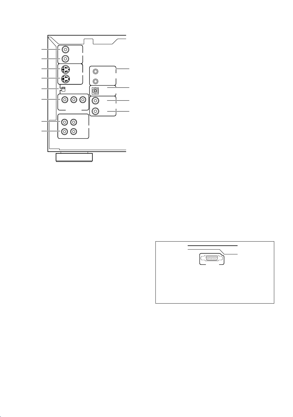
Rear Panel
INTERFACE
CONNECTOR
UDD1N
27122711
1
2
3
4
5
6
OUT
IN
OUT
IN
VIDEO SELECT
YP
BPR
COMPONENT
VIDEO OUT
R
L
7
8
1 VIDEO OUT jack
Connect the VIDEO OUT jack to the video input on a
TV or monitor or to an AV component with video input
capability. When using this jack, be sure to set VIDEO
SELECT to the top position (pages 15 and 18).
2 VIDEO IN jack
Connect the VIDEO IN jack to the video output of
another DPT-1 changer or another component with
video output capability (pages 67).
3 S-VIDEO OUT jack
If your TV or monitor has an S-video input, clear
picture reproduction is possible by connecting the
S-VIDEO OUT jack to your TV or monitor using a
commercially available S-video cable. When using
this jack, be sure to set VIDEO SELECT to the top
position (pages 16 and 18).
4 S-VIDEO IN jack
Connect the S-VIDEO IN jack to another DPT-1
changer or component with S-video output capability
(pages 67).
S
VIDEO
VIDEO
OUT
IN
AUDIO
VNA2176
MASTER
SLAVE
OUT
OUT
IN
MASTER-SLAVE
CONTROL
DIGITAL
(
)
OPTICAL
DIGITAL
(
)
COAXIAL
9
0
-
=
7 AUDIO OUT jacks
Connect to the stereo audio inputs of a TV or stereo
AV component. If you are connecting to an AV
component that has both digital and analog input
jacks for DVD player connection, it may be beneficial
to make both connections (pages 15 and 17).
8 AUDIO IN jacks
Connect to the analog audio outputs of another
DPT-1 or component with audio output capability
(pages 66).
9 MASTER-SLAVE CONTROL jacks
Connect two DPT-1 changers for singular control of
both changers and a total of 601 discs. Connect the
MASTER jack on the changer to be used as the
“Master” to the SLAVE jack of a second “Slave”
changer using the supplied Master-Slave control
cord. Do not attempt to make connections to other
components using this jack (page 66).
0 DIGITAL (OPTICAL) OUT jack
Connect the DIGITAL (OPTICAL) OUT to the digital
optical input of an AV component with a
built-in decoder, etc. to output the digital audio signal
recorded on discs. (page 17).
- DIGITAL (COAXIAL) OUT jack
Connect the DIGITAL (COAXIAL) OUT to the digital
coaxial input of an AV component to output the digital
audio signal recorded on discs (pages 16 and 17).
= DIGITAL (COAXIAL) IN jack
Connect the DIGITAL (COAXIAL) IN jack of another
DPT-1 changer or another component with digital
output (coaxial) capability (pages 66).
INTERFACE CONNECTOR jack
This jack is intended for use by a system
commander in the integration of some systems.
Normally, this jack is not used.
5 VIDEO SELECT switch
Use to set which output is used to output the video
signals. Set to the top position for composite video
and S-video output and to the bottom position for
component video output (pages 15, 16, and 18).
6 COMPONENT VIDEO OUT jacks
If your TV, projection monitor, projector, or similar
component has component video inputs, you can
produce a high quality picture by connecting to the
component video outputs on this unit. When using
these jacks, be sure to set VIDEO SELECT to the
bottom position (page 18).
14
Page 15

Making
Connections
Connecting Your DVD Changer
Unlike any other audiovisual media format, DVD offers a
wide array of audio and video output options which
allows playback to be enjoyed in any number of system
configurations from a standard TV with stereo audio
input to a home theater system with a projection
monitor and full surround sound capabilities.
Connecting two DPT-1 changers?
If you have chosen to purchase two DPT-1 changers for
combined control of up to 601 discs, make connections
to the changer to be used as the Master changer
following the procedures in this section. When
connections are complete, refer to page 66 for a
description of how to connect the Slave changer.
Connection Guide
The illustration on this page shows the basic setup using
the audio and video cords included with this changer.
Use this illustration as a guide to setting up your home
system.
An explanation of each type of audio and video
connection available can be found on pages 17 and 18.
To determine the best audio and video connection setup
for your system, refer to the manuals supplied with the
components you are making connections to.
In addition to making physical connections to your TV or
monitor, it is also necessary to assign the TV screen size.
You can use the [Setup Navigator] in the Setup screen
General menu to set whether you are using a wide
screen or standard size TV or monitor (page 21).
Additionally, you can use the [TV Screen] setting in the
Setup screen Video menu (page 43).
Notes
• When making connections to this unit or when changing
connections, check that the unit is off by pressing
STANDBY/ON and unplug the power cord from the power
outlet.
• The video outputs on this changer uses copy protect circuitry
to prevent the video playback on DVDs from being copied. If
you connect the changer to a TV via a VCR, or record and play
back the contents of a disc with a VCR, the playback picture
may not be normal.
NAMES AND FUNCTIONS / MAKING CONNECTIONS
UDD1N
27122711
OUT
IN
VIDEO SELECT
YP
COMPONENT
VIDEO OUT
R
OUT
IN
BPR
L
S
VIDEO
VIDEO
OUT
IN
AUDIO
VNA2176
MASTER
SLAVE
OUT
OUT
IN
MASTER-SLAVE
CONTROL
DIGITAL
(
)
OPTICAL
DIGITAL
(
)
COAXIAL
2
VIDEO SELECT
DVD CHANGER
MODEL NO.
DPT-1
Audio cord
(Included)
TV or monitor
REGIONAL CODE
INTERFACE
CONNECTOR
AC INLET
1
3
Video cord
(Included)
AUDIO IN
RL
4
1
VIDEO IN
S-VIDEO IN
1 Make video connections from the VIDEO OUT jack on the changer to the VIDEO IN jack on the TV or
monitor using the video cord included with the changer (page 18).
2 When using the VIDEO OUT jack, set VIDEO SELECT to the top position.
3 Make audio connections from the AUDIO OUT jacks on the changer to the AUDIO IN jacks on the TV
or monitor using the stereo audio cord included with the changer. Be sure to match the color of the
plugs with the color of the jacks (red and white) (page 17).
4 After all connections have been made, connect to a power outlet.
15
Page 16

Home Theater Component Connections
The connections on this page demonstrate the versatility of this changer to conform to any number of home
entertainment systems. Please note that the illustration shown on this page is meant as an example. Please refer to
the manuals supplied with the components to which you are making connections to determine the best possible setup
for your home system.
An explanation of each type of audio and video connection available can be found on pages 17 and 18.
UDD1N
27122711
OUT
VIDEO SELECT
YP
COMPONENT
VIDEO OUT
R
S-video cord
(Not included)
1
S-VIDEO IN
VIDEO IN
IN
OUT
IN
BPR
L
S
VIDEO
VIDEO
OUT
IN
AUDIO
VNA2176
MASTER
MASTER-SLAVE
CONTROL
SLAVE
OUT
DIGITAL
(
OPTICAL
OUT
DIGITAL
(
COAXIAL
IN
TV or monitor with
S-video inputs
2
VIDEO SELECT
)
MODEL NO.
)
Coaxial cable
(Not included)
VIDEO EQUIPMENT
9C39
E160927
DVD CHANGER
DPT-1
REGIONAL CODE
3
1
DIGITAL IN
INTERFACE
CONNECTOR
AC INLET
AV amplifier or receiver
4
5.1 Channel Surround Speaker System
1 S-video connection to a TV or monitor with S-video inputs (page 18)*.
2 When using the S-VIDEO OUT jack, set VIDEO SELECT to the top position.
3 Digital audio connections to an AV component with a built-in decoder, etc. (page 17).
4 After all connections have been made, connect to a power outlet.
* It may be possible to make video connections through your AV receiver or amplifier. Please refer to the manual supplied with your
component for more information.
16
Page 17

Audio Connections
This changer features two digital (optical and coaxial) and
also analog audio output connection possibilities.
Digital Audio Connections:
You can enjoy the digital audio recorded on DVD discs
from both optical digital and coaxial digital output jacks.
When making digital audio connections, use either
the coaxial or the optical output jack. It is not
necessary to make connections to both digital
output jacks.
DIGITAL (COAXIAL) OUT
The digital signal is transmitted electronically through a
coaxial cable.
• Use a commercially available coaxial cable to connect
the coaxial digital output on the changer to the coaxial
digital input on an AV component.
OUT
VIDEO SELECT
YP
COMPONENT
VIDEO OUT
R
VIDEO
IN
OUT
MASTER
VIDEO
S
MASTER-SLAVE
CONTROL
IN
SLAVE
OUT
DIGITAL
(
)
OPTICAL
DVD CHANGER
MODEL NO.
OUT
BPR
IN
L
OUT
AUDIO
IN
DPT-1
DIGITAL
(
)
COAXIAL
REGIONAL CODE
INTERFACE
CONNECTOR
AC INLET
1
When a DVD recorded in Dolby Digital, DTS, or MPEG is
playing, noise will be output if you have made
connections via the digital audio jacks to an AV
component that cannot decode a Dolby Digital, DTS, or
MPEG digital bitstream. In this case, be sure to set up
the Setup Navigator audio settings to best reflect the
type of system you are using (page 21). Additionally, the
digital audio settings can be adjusted manually in the
Setup screen Audio 1 menu (page 41).
DIGITAL (OPTICAL) OUT
The digital signal is transmitted as light pulses through a
fiber-optic cable.
• Use a commercially available fiber-optic cable to
connect the DIGITAL (OPTICAL) OUT on the changer
to the digital optical input on an AV component.
OUT
VIDEO SELECT
YP
COMPONENT
VIDEO OUT
R
VIDEO
IN
OUT
MASTER
S
VIDEO
MASTER-SLAVE
CONTROL
IN
SLAVE
OUT
DIGITAL
(
)
OPTICAL
DVD CHANGER
MODEL NO.
OUT
BPR
IN
L
OUT
AUDIO
IN
DPT-1
DIGITAL
(
)
COAXIAL
REGIONAL CODE
OUT
DIGITAL
(
)
OPTICAL
OUT
DIGITAL
(
)
COAXIAL
IN
INTERFACE
CONNECTOR
AC INLET
1
DIGITAL IN
OUT
DIGITAL
(
)
OPTICAL
OUT
DIGITAL
(
)
COAXIAL
IN
DIGITAL IN
AV component with built-in
Dolby Digital, DTS, or MPEG
decoder, etc.
Analog Audio Connections:
AUDIO OUT
• Analog audio connections can be made to a stereo
amplifier or receiver, or also can be made to a TV or
monitor with stereo input jacks.
• Use the supplied audio cable to connect the AUDIO
OUT jacks on the changer to the audio input jacks on a
stereo amplifier or receiver.
• When making analog audio connections, be sure to
match the color of the plugs with the color of the
jacks (red and white).
OUT
VIDEO SELECT
YP
COMPONENT
VIDEO OUT
R
VIDEO
IN
OUT
MASTER
S
VIDEO
MASTER-SLAVE
CONTROL
IN
SLAVE
OUT
DIGITAL
(
)
OPTICAL
DVD CHANGER
MODEL NO.
OUT
B PR
IN
L
OUT
AUDIO
IN
DPT-1
DIGITAL
(
)
COAXIAL
REGIONAL CODE
INTERFACE
CONNECTOR
AC INLET
1
MAKING CONNECTIONS
AV amplifier or receiver with
built-in Dolby Digital, DTS, or
MPEG decoder, etc.
R
L
OUT
AUDIO
IN
AUDIO IN
RL
Stereo amplifier or receiver
17
Page 18

Video Connections
This changer features S-video, composite, and
component video output possibilities. Check the manual
supplied with your TV or monitor to determine the best
possible connection for your system.
In addition to making physical connections to your TV or
monitor, it is also necessary to assign the TV screen size.
You can use the [Setup Navigator] in the Setup screen
General to set whether you are using a wide screen or
standard size TV or monitor (page 21). Additionally, you
can use the [TV Screen] setting in the Setup screen
Video menu (page 43).
VIDEO OUT
• Make composite video connections to a standard TV
or monitor with a video input jack.
• Use the supplied video cable to connect the VIDEO
OUT jack on the changer to the video input on the TV
or monitor.
• Be sure to match the color of the plug with the color
of the jack (yellow).
• When making video connections, make sure to set VIDEO
SELECT on the rear panel of the changer to the top
position to assign composite video output.
OUT
VIDEO SELECT
VIDEO SELECT
YP
COMPONENT
VIDEO OUT
R
VIDEO
IN
OUT
MASTER
VIDEO
S
MASTER-SLAVE
CONTROL
IN
SLAVE
OUT
DIGITAL
(
)
OPTICAL
OUT
DIGITAL
BPR
(
)
COAXIAL
IN
L
OUT
AUDIO
IN
REGIONAL CODE
OUT
VIDEO
IN
INTERFACE
CONNECTOR
AC INLET
1
VIDEO IN
TV or monitor
S-VIDEO OUT
• Make S-video connections to a TV or monitor with
S-video input to produce a high quality video image.
• Use a commercially available S-video cable to connect
the S-VIDEO OUT jack on the changer to an S-video
input on the TV or monitor.
• When making S-video connections, make sure to set
VIDEO SELECT on the rear panel of the changer to
the top position to assign S-video output.
OUT
VIDEO SELECT
VIDEO SELECT
YP
COMPONENT
VIDEO OUT
R
VIDEO
IN
OUT
MASTER
VIDEO
S
MASTER-SLAVE
CONTROL
IN
SLAVE
OUT
DIGITAL
(
)
OPTICAL
OUT
DIGITAL
BPR
(
)
COAXIAL
IN
L
OUT
AUDIO
IN
REGIONAL CODE
OUT
S VIDEO
IN
INTERFACE
CONNECTOR
AC INLET
1
S-VIDEO IN
TV or monitor
COMPONENT VIDEO OUT
• Make component video connections to a TV, projection
monitor, or projector with component inputs for an
exceptional video image that best portrays the high
quality digital video recorded on DVDs.
• Use a commercially available component video cable
or 3 video cords to connect the COMPONENT VIDEO
OUT jacks on the changer to the component jacks on
the monitor.
• When making component video connections, make
sure to set VIDEO SELECT on the rear panel of the
changer to the bottom position to assign component
video output.
OUT
VIDEO SELECT
VIDEO SELECT
YP
COMPONENT
VIDEO OUT
R
VIDEO
IN
OUT
MASTER
VIDEO
S
MASTER-SLAVE
CONTROL
IN
SLAVE
OUT
DIGITAL
(
)
OPTICAL
OUT
DIGITAL
BPR
(
)
COAXIAL
IN
L
OUT
AUDIO
IN
REGIONAL CODE
INTERFACE
CONNECTOR
AC INLET
1
18
YPBP
COMPONENT
VIDEO OUT
R
YPBP
R
COMPONENT
VIDEO IN
TV, projection monitor,
or projector
Page 19

MAKING CONNECTIONS
19
Page 20

Setting Up the
Setup Navigator
Audio1 GeneralLanguageVideo2
Move
Exit
SETUP
Select
ENTER
Setting up using the Setup Navigator
Setup Navigator
Not Used
Start
Changer
Using the Setup Navigator
The Setup Navigator has been designed to simplify the
process of getting the DVD changer ready to perform.
Designed as a series of on-screen multiple-choice
questions, the Setup Navigator automatically sets the
audio, video, and language settings according to how the
questions are answered. Once this procedure is
complete, it will be possible to begin using the DVD
changer to enjoy DVDs.
The procedure on this page describes the operations
necessary to function within the Setup Navigator
screens. A detailed description of the contents of each
question that appears on the screen can be found on
the following pages.
When setting up for the first time
If the disc rack is moving or if a disc is playing, the Setup
Navigator will not be displayed as described in the
procedure on this page. Therefore, it is recommended to
wait until the rack has stopped moving before using the
Setup Navigator. If a disc is playing, be sure to press
STOP 7 before proceeding.
2 Press SETUP.
When SETUP is pressed for the first time, the
following screen appears. Though the Setup
Navigator may be used more than once, this screen
only appears the first time SETUP is pressed.
3 Move the cursor control joystick up or down
to make a selection.
• If you are going to use the Setup Navigator, it is
not necessary to change the setting on the first
screen. Please proceed to the next step.
• If you do not want to set up the changer using
the Setup Navigator, move the cursor control
joystick to select “Not Used” at this time.
The Setup Navigator function may still be used at
a later time in manual Setup screen menu
operation (page 39).
4 Press ENTER.
The selection is entered and the next Setup
Navigator screen appears.
OPEN/
POWER
1
2
3
(Cursor)
Play Mode Random Display Input Search
Standby
Standby/On
Access Play
Text
Single Loader
CLOSE
DISPLAY AUDIO SUBTITLE ANGLE
SETUP
MENU
STUP T.MNU
MULTI DIAL
-
+
ENTER
FUNCTION
SELECT
MEMORY
DISC No.
DISC JOGDNR
F.MEM
3
0
1
D
is
c
Direct Digital Path
TOP MENU
JOG MODE
4
(ENTER)
Direct Custom
123
456
789
Update
Audio / Video
Clear
10
Keyboard / Mouse
/
CHARACTER
DISC
( Push To Enter )
PlayStop PauseOpen /Close
DPT-1
1
1 Press Power ( Standby/On on the front
panel).
5 Repeat steps 3 and 4 to answer the questions
on the all of the Setup Navigator screens as
described on the following pages.
To change the answer to a prior question
Move the cursor control joystick left to return to previous
screens. Please note, however, that you cannot go
forward by moving the cursor control joystick right, so it
will be necessary to answer all the questions that occur
after the screen that was returned to.
To exit the Setup Navigator
Press SETUP while on any of the screens to exit the
Setup Navigator. Please note that if the Setup Navigator
is exited before all the questions are answered, no
settings are changed.
To return to the Setup screen
Press RETURN . The Setup Navigator is exited and
the Setup screen General menu screen appears. Please
note that no settings are changed if RETURN is
pressed before the Setup Navigator is finished.
20
Page 21

Setting the OSD Language
Setup Navigator
Audio1 GeneralLanguageVideo2
Move
Exit
SETUP
Select
ENTER
Compatible with Dolby Digital
Digital Jacks
Not Connected
Dolby D/DTS/MPEG
Dolby Digital/MPEG
Dolby Digital/DTS
PCM
Dolby Digital
Amp Connection
(On-Screen Display Language)
The [OSD Language] screen establishes the OSD
language, or on-screen display language, which refers to
the language that is used by the changer in menus and
on-screen messages. Additionally, the language that is
established at this setting will also be set as the audio
and subtitle language.
Audio1 GeneralLanguageVideo2
Setup Navigator
Language
OSD Language
Setup player's OSD language
Move
ENTER
English
français
Español
Select
SETUP
Exit
Setting digital audio connections
to an AV amplifier or decoder
The [Digital Jacks] screen establishes what kind of digital
connections have been made to an AV amplifier,
receiver, or external decoder. Please refer to the
instructions supplied with the component the player is
connected to determine what digital audio formats can
be decoded. If you have made no digital connections,
select “Not Connected”.
Settings: English*
français
Español
* Factory setting
Note
In addition to setting the OSD language, the audio and subtitle
language are also set at this time. If you wish to change the
audio or subtitle language to a different language, make changes
in the Setup screen Language menu [Audio Language] and
[Subtitle Language] as needed (page 46).
Setting the TV screen size
The [TV Connection] screen establishes the size, or
more appropriately, the width to height ratio of your
television or monitor. The width-to-height ratio of
conventional TVs is 4:3, while the width-to-height ratio of
wide screen and high-definition TVs is 16:9. This widthto-height ratio is called the aspect ratio.
Audio1 GeneralLanguageVideo2
Setup Navigator
TV Connection
TV Type
Widescreen (16:9)
Move
Standard (4:3)
ENTER
Select
SETUP
Exit
* Factory setting
Widescreen TV
16:9 aspect ratio
Settings: Widescreen (16:9)*
Standard (4:3)
Settings: Dolby Digital*
Select if the connected AV component is
capable of decoding the Dolby Digital
bitstream.
Dolby Digital/DTS
Select if the connected AV component is
capable of decoding Dolby Digital and DTS
bitstreams.
Dolby Digital/MPEG
Select if the connected AV component is
capable of decoding Dolby Digital and MPEG
bitstreams.
Dolby D/DTS/MPEG
Select if the connected AV component is
capable of decoding Dolby Digital, DTS, and
MPEG bitstreams.
PCM
Select if the connected AV component has
digital input jacks but no internal decoder.
Not Connected
No digital audio connections have been made.
SETTING UP THE CHANGER
* Factory setting
Notes
• There are two screen formats that can be used to display
wide-screen format DVDs: letter box and pan & scan. When
“Standard (4:3)” is selected in the Setup Navigator, the letter
box screen format is automatically selected. To switch the
preference to the pan & scan format, make changes in the
Setup screen Video menu [TV Screen] setting (page 43).
• When “Standard (4:3)” is selected in the Setup Navigator,
Linear PCM digital audio playback is output is automatically
downsampled to 48 kHz (when the original signal is 96 kHz). In
order to hear audio at the sampling rate of 96 kHz, set the
Setup screen Video menu [TV Screen] setting to either
“Wide” or “4:3 (Pan & Scan)” (page 43). Additionally, make
sure that your system is set up to output the 96 kHz bitstream
using either the Setup Navigator or the Setup screen Audio 1
menu [96kHz PCM Out] setting (this page and page 41
respectively).
21
Page 22

Setup Navigator
Audio1 GeneralLanguageVideo2
Move
Exit
SETUP
Select
ENTER
Confirm setup adjustments
Exit Setup Navigator
Redo
Invalid
Valid
Setting compatibility with 96 kHz
output
The [96 kHz PCM Audio] screen establishes whether or
not the AV component the changer is connected to is
capable of processing an audio signal with a sampling
rate of 96 kHz. This screen only appears if connections
have been made to an external AV component as
determined in the previous screen.
Audio1 GeneralLanguageVideo2
Setup Navigator
Amp Connection
96 kHz PCM Audio
Digital jack not compatible with 96 kHz
Settings: No*
Select if the connected AV component cannot
process an audio signal with a sampling rate of
96 kHz.
Yes
Select if the connected AV component can
process an audio signal with a sampling rate of
96 kHz.
Don’t Know
Select if you are uncertain whether the
connected AV component can process an
audio signal with a sampling rate of 96 kHz.
Note
When a DVD is played back in the letter box format, Linear PCM
digital audio output is automatically downsampled to 48 kHz
(when the original signal is 96 kHz). In order to hear audio at the
sampling rate of 96 kHz, set the Setup screen Video menu [TV
Screen] setting to either “Wide” or “4:3 (Pan & Scan)” (page 43).
Move
ENTER
No
Yes
Don't Know
SETUP
Select
Exit
* Factory setting
Confirming the settings
The [Exit Setup Navigator] is the final screen in the Setup
Navigator.
Settings: Valid*
Select to have the changer make all of the
necessary audio, video and language settings
automatically.
Invalid
Select to exit the Setup Navigator without
changing any of the system settings.
Redo
Select to return to the [OSD Language] screen
of the Setup Navigator and do the settings
again.
* Factory setting
To exit the Setup screen
When you have completed setting up the changer using
the Setup Navigator or if you exit the Setup Navigator,
the Setup screen General menu appears. Press Setup
to close the Setup screen.
To change other player settings in the Setup screen
menus
The procedure for changing the settings in the Setup
screen menus is described on page 39.
22
Page 23

Getting Started
Using Your DVD
Changer
Loading DVDs, Video CDs and
CDs into the Changer– DVD/Video CD/CD
You can load as many as 300 discs into the rack. Disc
positions in the rack are numbered clockwise from 1 to
300 starting after the single loader slot. The procedure
on this page describes how to load discs starting from
the number 1 position. However, the same procedure
can be followed when you want to change or add more
discs at a different time.
3 Load discs in the rack.
• The number 1 position is immediately to the left
of the single loader slot.
• Load discs with the label side facing to the right.
(When loading double-sided DVDs, load the disc
in the rack with the label denoting the contents
you want to view facing the right.)
• Do not place more than one disc in the same rack
position as that may damage the disc and cause
the changer to malfunction.
Label side
D
I
S
C
/
C
H
A
R
A
C
T
E
R
(
P
u
s
h
T
o
E
n
t
e
r
)
Direct Custom
1
2
3
4
5
P
l
a
y
M
o
d
e
Rand
om
D
isp
la
y
In
p
u
t
S
e
a
r
c
h
T
e
x
t
S
ta
n
d
by
S
tandby/On
S
i
n
g
l
e
L
o
a
d
e
r
Ac
c
e
ss
P
l
a
y
6
7
8
9
A
u
dio
/ Vi
deo
U
p
d
a
t
e
C
l
e
a
r
1
0
O
p
e
n
/
C
l
o
s
e
Stop
P
la
y
P
a
u
s
e
K
e
y
b
o
a
r
d
/
M
o
u
s
e
DPT-1
OPEN/
POWER
1
CLOSE
DISPLAY AUDIO SUBTITLE ANGLE
SETUP
MENU
STUP T.MNU
MULTI DIAL
-
+
ENTER
FUNCTION
SELECT
MEMORY
DISC No.
DISC JOGDNR
F.MEM
STOP PLAY PAUSE
RETURN STEP
/
SLOW
SEARCH MODE
1
3C
2
TOP MENU
JOG MODE
CLEAR
2,6
4
Dial mode
indicator
4
43
DISC
/
CHARACTER
( Push To Enter )
Direct Custom
123
456
789
Audio / Video
Update
Play Mode Random Display Input Search
Text
Standby
Single Loader
Standby/On
Access Play
3
Direct Digital Path
0
1
D
is
c
Clear
10
PlayStop PauseOpen /Close
Keyboard / Mouse
DPT-1
1 2,6
1 Press POWER ( Standby/On on the front
panel).
2 Press OPEN/CLOSE 0 (Open/Close on the
front panel).
The disc rack hood slides open.
4 Press SELECT DISC NUMBER (the dial mode
indicator lights green) and then turn MULTI
DIAL to rotate the rack to the next position.
When using the front panel, turn the selection
dial clockwise to rotate the rack to the next
disc position.
• The rack rotates the amount that either MULTI
DIAL or the selection dial is turned.
• Turning the MULTI DIAL or the selection dial
counterclockwise rotates the rack in the opposite
direction.
5 Repeat steps 3 and 4 to continue loading
discs in the rack.
6 When you have finished loading discs into the
rack, press OPEN/CLOSE 0 (Open/Close on
the front panel).
The hood slides closed and the rack makes a single
revolution while the changer determines where
discs have been loaded in the rack.
D
I
S
C
/
C
H
A
R
A
C
T
E
R
(
P
u
s
h
T
o
E
n
t
e
r
)
Direct Custom
1
2
3
4
5
P
l
a
y
M
o
d
e
Random
D
is
pla
y
In
p
u
t
S
e
a
r
c
h
T
e
x
t
S
ta
n
d
b
y
Standby/O
n
S
i
n
g
l
e
L
o
a
d
e
r
A
cce
ss
P
l
a
y
6
7
8
9
A
udio / V
ideo
U
p
d
a
t
e
C
l
e
a
r
1
0
O
p
e
n
/C
lo
s
e
Stop
P
la
y
P
a
u
s
e
K
e
y
b
o
a
r
d
/
M
o
u
s
e
DPT-1
SETTING UP THE CHANGER / GETTING STARTED USING YOUR DVD CHANGER
D
I
S
C
/
C
H
A
R
A
C
T
E
R
(
P
u
s
h
T
o
E
n
t
e
r
)
Direct Custom
1
2
3
4
5
P
l
a
y
M
o
d
e
Random
D
isplay
I
n
p
u
t
S
e
a
r
c
h
T
e
x
t
S
ta
n
db
y
S
tandby/On
S
i
n
g
l
e
L
o
a
d
e
r
A
cce
ss
P
l
a
y
6
7
8
9
A
udio / V
ideo
U
p
d
a
t
e
C
l
e
a
r
1
0
O
p
e
n
/C
lo
s
e
Stop
Play
P
a
u
s
K
e
e
y
b
o
a
r
d
/
M
o
u
s
e
DPT-1
Note
Never force the hood open or closed. Doing so may cause part
damage or changer malfunction.
23
Page 24

To load a 3 inch (8 cm) CD
3 inch (8 cm) discs cannot be inserted as they are. Be
sure to attach all 3 inch (8 cm) CDs to a commercially
available disc adapter before loading them in the
changer.
• Do not load an adapter into the rack without a CD
attached. Doing so may cause the changer to
malfunction.
• 3 inch (8 cm) DVDs cannot be used with this changer.
To prevent malfunction, do not use 8 cm (3 in.) CD
adapters with 8 cm (3 in.) DVDs.
To remove discs from the rack
1 Press OPEN/CLOSE 0 (OPEN/CLOSE on the front
panel) to open the hood.
2 Select the disc that you want to remove using one of
the methods outlined in step 4 of the procedure
“Loading DVDs, Video CDs and CDs into the
Changer” on the previous page.
3 Remove the disc from the rack.
4 Press OPEN/CLOSE 0 (OPEN/CLOSE on the front
panel) to close the hood when you are finished.
WARNING
Do not put your hand or any other object inside the
rack, as this may result in personal injury and/or part
damage.
Playing DVDs, Video CDs and
CDs – DVD/Video CD/CD
Before you can start to enjoy the digital audio and video
on DVDs, be sure that you have either performed the
Setup Navigator procedure described in the previous
section or made the necessary settings in the Setup
screen menus as outlined in the section starting on page
39 to set up the player to correspond to your home
system. Having made these settings, you are now
ready to start using the player to enjoy DVDs, Video
CDs, and CDs.
Make sure that you have already loaded the rack as
described in the section starting on the previous page.
To play a disc
OPEN/
POWER
1
2
CLOSE
DISPLAY AUDIO SUBTITLE ANGLE
SETUP
MENU
STUP T.MNU
MULTI DIAL
-
ENTER
FUNCTION
SELECT
MEMORY
DISC No.
DISC JOGDNR
F.MEM
STOP PLAY PAUSE
TOP MENU
+
JOG MODE
D
I
S
C
/
C
H
A
R
A
C
T
E
R
(
P
u
s
h
T
o
E
n
t
e
r
)
Direct Custom
1
2
3
4
5
P
l
a
y
M
o
d
e
R
andom
D
isp
la
y
In
p
u
t
S
e
a
r
c
h
T
e
x
t
S
ta
n
d
b
y
Standby/On
S
i
n
g
l
e
L
o
a
d
e
r
A
cc
e
ss
P
l
a
y
6
7
8
9
A
udio / Video
U
p
d
a
t
e
C
l
e
a
r
1
0
O
p
e
n
/C
lo
s
e
Stop
Play
P
a
u
s
e
K
e
y
b
o
a
r
d
/
M
o
u
s
e
DPT-1
• When changing or loading discs, be careful not to
press any buttons on the changer or remote
controller. The rack may move suddenly, and may
catch your fingers between discs and the side of
the hood.
• When changing or loading discs, make sure the
rack is stopped. Do not attempt to insert a disc
while the rack is moving.
RETURN STEP
/
SLOW
SEARCH MODE
Direct Digital Path
CLEAR
3C
2
DISC
/
CHARACTER
( Push To Enter )
Direct Custom
123
456
789
Audio / Video
Update
Clear
10
3
0
1
is
D
c
PlayStop PauseOpen /Close
Keyboard / Mouse
DPT-1
Play Mode Random Display Input Search
Text
Standby
Single Loader
Standby/On
Access Play
1
12
1 Press POWER ( Standby/On on the front
panel).
2 Press PLAY 3 (Play on the front panel).
• If a play mode has been previously selected,
disc(s) will be played according to the selected
play mode (page 26).
• When a disc containing text or a disc that has had
text information input is played, the text
information appears in the display window. Refer
to page 31 for information on inputting text.
• Depending on the disc, a menu may be
displayed. The section ‘When a menu screen
is displayed’ on the following page provides
general guidelines for understanding menu
screens.
24
Page 25

Notes
• Noise is output if you make digital audio connections to a
receiver or amplifier that does not have a built-in decoder.
Check that the digital audio output format selected in the
Audio 1 menu corresponds to the audio components you have
made connections to (page 41).
• The TV screen size is factory set to present the wide screen
format (16:9 aspect ratio). If you have a standard TV screen
(4:3 aspect ratio), this setting can be changed to match your TV
screen size in the Video menu (page 43).
When an operation is prohibited
There are times when you are using the changer and attempt
to perform an operation, but for some reason it cannot be
performed. When this occurs, one of the two following icons
appears on the screen.
The operation is prohibited by the changer.
The operation is prohibited by the programming on
the disc.
Example: When a Video CD that has Playback Control is
selected
STANDARD VOCAL BEST
1
Don't Tekno for an Answer
2
Bad Whack Naff Riff
3
dubmyheadbassman
4
Gooey Love Jingle
5
Praise the Day
6
G3, Ba-san
7
Abstract Jazz Phunk
8
Rock the Love Jive
Bertie B.& the Goans
Hood in the Boyz
Sleek Machine
Philip William
Formerly an Artist
Pfeuti
John Torn
Hot Monkey Stick
To open or return to the DVD or Video CD
menu screen
Although this differs depending on the disc, pressing
MENU, TOP MENU, or RETURN during DVD
playback or RETURN during Video CD playback
displays the menu screen. Refer to the DVD or Video CD
disc jacket and accompanying documentation for more
information.
When a menu screen is displayed
Menu screens are displayed for DVDs that have menu
screens or Video CDs that include PBC (Playback Control).
DVDs often contain extra information that can be
accessed in the DVD menu and sometimes makes
navigating DVD menu screens as enjoyable as watching
the feature presentation.
OPEN/
POWER
Cursor control
joystick
STOP7
4
RETURN
Number buttons
CLOSE
DISPLAY AUDIO SUBTITLE ANGLE
SETUP
MENU
STUP T.MNU
MULTI DIAL
-
+
ENTER
FUNCTION
SELECT
DISC No.
MEMORY
F.MEM
STOP PLAY PAUSE
RETURN STEP
1
45
78
RANDOM REPEAT
SUB
SETUP
HI-LITE
LAST
MEMORY
PREVIOUS
SCAN
2
DISC
/
SLOW
3C
6
9
-
A
CONDITION
MEMORY
BEST
JOG MODE
SEARCH MODE
BRPTRDM PGM
TOP MENU
JOGDNR
CLEAR
+10
0
PROGRAM
PLAY
MODE
MENU
TOP MENU
ENTER
¢
To navigate a menu screen
• Although individual DVD titles may differ, when a menu
screen is displayed, use the cursor control joystick and
ENTER on the remote controller. The cursor control
joystick is used to move around the options on the
screen and ENTER is used for selection. Occasionally,
the number buttons may also be used to make
selections. If this is possible, using number buttons
serves to directly select an option on a menu screen.
• Only number buttons are used to make selections on
Video CD menu screens.
• When the Video CD has more than one menu, pages
can be advanced to or returned to with 4 or ¢.
Turning PBC (Playback Control) on and off
When playing Video CDs with PBC (Playback Control),
PBC is technically on by default and a menu screen is
displayed. Additionally, the menu screen is returned to
when the selected track is complete.
If you would like to turn PBC off so that the menu
screen is not displayed, press STOP 7 when a Video CD
with PBC is selected and then press the number button
of the track you want to play. Please note that a number
of functions such as random and program playback may
not be possible unless PBC is turned off.
GETTING STARTED USING YOUR DVD CHANGER
REMOTE CONTROLLER
-
416
DV
RC
Example: When a DVD that has menu screens is
selected
1 Highlight Clips
2 Chapter List
3 CommercialHeader
4 Subtitles
5 Soundtrack
6 StartMainFeature
25
Page 26

Selecting a disc in the disc rack
Selecting a play mode
OPEN/
POWER
CLOSE
2
DISPLAY AUDIO SUBTITLE ANGLE
SETUP
STUP T.MNU
TOP MENU
MENU
MULTI DIAL
-
+
ENTER
1
Dial mode
FUNCTION
SELECT
MEMORY
DISC No.
DISC JOGDNR
F.MEM
STOP PLAY PAUSE
RETURN STEP
/
SLOW
1
3C
2
JOG MODE
SEARCH MODE
indicator
1
CLEAR
1,2
DISC
/
CHARACTER
( Push To Enter )
Direct Custom
123
456
789
Audio / Video
Update
Play Mode Random Display Input Search
Text
Standby
Single Loader
Standby/On
Access Play
3
0
Direct Digital Path
1
D
is
c
Clear
10
PlayStop PauseOpen /Close
Keyboard / Mouse
DPT-1
1 Press SELECT DISC NUMBER (the dial mode
indicator lights green) and then turn MULTI
DIAL to select a disc number.
When using the front panel, turn the selection
dial to select a disc number.
• The disc numbers increase when MULTI DIAL or
the selection dial is turned clockwise, and
decrease when MULTI DIAL or the selection dial
is turned counterclockwise
2 Press ENTER.
When using the front panel, press the
selection dial in the center of the selection
dial.
• The disc rack rotates to position of the selected
disc, and playback of the disc starts.
Note
You can also select a disc on-screen using the Sub Setup screen
Text menu (page 35).
STOP PLAY PAUSE
/
SLOW
1
78
LAST
MEMORY
PREVIOUS
SCAN
REMOTE CONTROLLER
2
RC
-
416
3
Direct Digital Path
CONDITION
MEMORY
DV
0
1
D
SEARCH MODE
3C
6
9
PROGRAM
A-BRPTRDM PGM
BEST
is
c
CLEAR
MODE
+10
0
PLAY
PLAY
MODE
DISC
/
CHARACTER
( Push To Enter )
Direct Custom
123
456
789
Update
Audio / Video
Clear
10
PlayStop PauseOpen /Close
Keyboard / Mouse
DPT-1
Play Mode Random Display Input Search
Text
Standby
Single Loader
Standby/On
Access Play
RETURN STEP
45
RANDOM REPEAT
SUB
SETUP
HI-LITE
Play Mode
Press PLAY MODE repeatedly to select one of
the play modes:
ALL : All discs of the same format as the currently
SINGLE : One disc is played. Playback stops after the
CUSTOM : Only discs in the custom file are played back.
The play mode changes each time PLAY MODE is
pressed as follows.
While disc playback is stopped:
During disc playback:
• The ALL, SINGLE, CUSTOM AUDIO, or CUSTOM
VIDEO indicators appear in the display window to
indicate the current play mode.
• ALL play ends after a full revolution of the rack has been
made from the position of the currently selected disc.
• CUSTOM AUDIO and CUSTOM VIDEO cannot be
selected until custom files have been created.
selected disc are played back in the order
they appear in the rack.
disc has been played.
3 ALL 3 SINGLE
CUSTOM VIDEO 2 CUSTOM AUDIO 2
3 ALL
SINGLE 2
26
To create and select one of the custom play modes
Refer to the section ‘Creating and selecting custom files’
on page 37.
Notes
• If PLAY MODE is pressed during program play, the program is
erased.
• The play mode is stored in memory when the changer is turned
off, and is established when the changer is turned on again.
• If no play mode is selected, the default play mode is ALL play.
• The single play mode is automatically set when the disc in the
single loader slot is being played (page 28).
Page 27

Chapter (Track) Skip Forward/
Skip Back – DVD/Video CD/CD
FUNCTION
SELECT
MEMORY
DISC No.
JOG MODE
JOGDNR
DISC
F.MEM
STOP PLAY PAUSE
4
Play Mode Random Display Input Search
Text
Standby
Single Loader
Standby/On
Access Play
RETURN STEP
1
45
78
RANDOM REPEAT
SUB
SETUP
MEMORY
PREVIOUS
HI-LITE
REMOTE CONTROLLER
3
0
Direct Digital Path
/
SLOW
SEARCH MODE
3C
2
6
9
PROGRAM
-
BRPTRDM PGM
A
LAST
CONDITION
MEMORY
BEST
SCAN
-
416
DV
RC
1
D
is
c
CLEAR
MODE
¢
+10
0
PLAY
DISC
/
CHARACTER
( Push To Enter )
Direct Custom
123
456
789
Update
Audio / Video
Clear
10
PlayStop PauseOpen /Close
Keyboard / Mouse
DPT-1
¡ ¢4 1
Advancing to the next chapter
(track)
Press ¢ (¡ ¢ on the front panel).
• Press to skip forward to the next chapter (track).
• When a CD is playing, you can advance more than one
track forward by pressing and holding ¢ and
releasing when the desired track number appears in
the display window.
Skipping back to the previous
chapter (track)
Press 4 (4 1 on the front panel).
• Press once to skip back to the start of the chapter
(track) currently playing.
• Press twice to skip back to the start of the previous
chapter (track).
• When a CD is playing, you can skip back to the track
you want to hear by pressing and holding 4 and
releasing when the desired track number appears in
the display window.
Forward and Reverse Scanning
– DVD/Video CD/CD
FUNCTION
SELECT
MEMORY
DISC No.
JOG MODE
DISC
1
Play Mode Random Display Input Search
Text
Standby
Single Loader
Standby/On
Access Play
F.MEM
STOP PLAY PAUSE
RETURN STEP
1
45
78
RANDOM REPEAT
SUB
SETUP
HI-LITE
/
SLOW
2
A
LAST
CONDITION
MEMORY
MEMORY
PREVIOUS
BEST
SCAN
REMOTE CONTROLLER
-
416
DV
RC
3
0
1
D
is
c
Direct Digital Path
JOGDNR
SEARCH MODE
CLEAR
3C
6
+10
9
0
PROGRAM
-
BRPTRDM PGM
PLAY
MODE
Direct Custom
123
456
789
Audio / Video
10
Keyboard / Mouse
PLAY3
¡
DISC
/
CHARACTER
( Push To Enter )
Update
Clear
PlayStop PauseOpen /Close
Play
DPT-1
¡ ¢4 1
Fast forward scanning
Press and hold ¡ (¡ ¢ on the front panel)
during playback.
• Release ¡ when you reach the desired location.
Normal playback resumes.
• Two speeds of scanning, “SCAN 1” and “SCAN 2”,
are performed in the forward direction, with “SCAN
2” being the faster of the two scanning speeds.
• When the flashing “SCAN 1” on the screen changes
to a flashing “SCAN 2”, fast forward scanning will
continue even if the button is released. When the
desired location has been reached, press PLAY 3.
• Variable speed scanning is also possible using MULTI
DIAL on the remote controller (page 53).
Fast reverse scanning
Press and hold 1 (4 1 on the front panel)
during playback.
• Release 1 when you reach the desired location.
Normal playback resumes.
• The three scanning speeds that this player uses
increase in speed from “SCAN 1” to “SCAN 3”
• On DVDs, when the flashing “SCAN 2” on the screen
changes to a flashing “SCAN 3”, fast reverse
scanning will continue even if the button is released.
On Video CDs and CDs, the scanning speeds are
“SCAN 1” and “SCAN 2”. When the desired location
has been reached, press PLAY 3.
• Variable speed scanning is also possible using MULTI
DIAL on the remote controller (page 53).
GETTING STARTED USING YOUR DVD CHANGER
27
Page 28

Playing a Disc That Is Not
Loaded in the Rack
(Single Loader Play)
By using the single loader slot, you can quickly load
discs, such as rental DVDs, that you may not want to
have loaded in the changer all of the time. With the
touch of a single button, this disc can be called up and
played at any time.
Selection dial
DISC
/
CHARACTER
( Push To Enter )
Direct Custom
123
456
789
Update
Audio / Video
Play Mode Random Display Input Search
Text
Standby
Single Loader
Standby/On
Access Play
1 2
3
3
0
Direct Digital Path
1
D
is
c
1 Press Single Loader Access on the front
panel.
The rack rotates to the single loader slot and the
hood opens automatically.
Clear
10
PlayStop PauseOpen /Close
Keyboard / Mouse
DPT-1
3 Press Single Loader Play on the front panel.
• The hood closes automatically and playback of
the disc in the single loader slot begins.
• The play mode is automatically set to SINGLE.
D
I
S
C
/
C
H
A
R
A
C
T
E
R
(
P
u
s
h
T
o
E
n
t
e
r
)
Direct Cust
om
1
2
3
4
5
P
l
a
y
M
o
d
e
Ran
dom
D
is
p
la
y
In
p
u
t
S
e
a
r
c
h
T
e
x
t
S
ta
n
d
b
y
Stand
by/O
n
S
i
n
g
l
e
L
o
a
d
e
r
A
c
ce
ss
P
l
a
y
Notes
• The disc in the single loader slot can also be selected with the
selection dial on the front panel. Turn the selection dial to
select the “P0” disc position between 1 and 300.
• By pressing SELECT DISC NUMBER on the remote controller
(the Jog mode indicator light green), you can also turn MULTI
DIAL to select the “P0” disc position between 1 and 300.
• If a disc is loaded in the single loader slot, pressing Single
Loader Play allows you to play the disc at any time, even
during playback of a disc loaded in the rack.
• When Master-Slave connections are made, single loader play
on the Slave changer cannot be performed.
6
7
8
9
Aud
io / V
id
eo
U
p
d
a
t
e
C
le
a
r
1
0
O
p
e
n
/
C
l
o
s
e
Stop
P
l
a
y
P
a
u
s
e
K
e
y
b
o
a
r
d
/
M
o
u
s
e
DPT-1
D
I
S
C
/
C
H
A
R
A
C
T
E
R
(
P
u
s
h
T
o
E
n
t
e
r
)
Direct Custom
1
2
3
4
5
P
l
a
y
M
o
d
e
Random
D
isplay
In
p
u
t
S
e
a
r
c
h
T
e
x
t
S
ta
n
d
b
y
Standby/On
S
i
n
g
l
e
L
o
a
d
e
r
A
cc
e
ss
P
l
a
y
6
7
8
9
Audio / Video
U
p
d
a
t
e
C
l
e
a
r
1
0
O
p
e
n
/C
lo
s
e
Stop
Play
P
a
u
s
K
e
e
y
b
o
a
r
d
/
M
o
u
s
e
DPT-1
2 Load a disc in the single loader slot with the
label side facing the right. (When loading
double-sided DVDs, load the disc in the rack
with the label denoting the contents you want
to view facing the right.)
Label side
D
I
S
C
/
C
H
A
R
A
C
T
E
R
(
P
u
s
h
T
o
E
n
t
e
r
)
Direct Custom
1
2
3
4
5
P
l
a
y
M
o
d
e
Random
D
is
pla
y
In
p
u
t
S
e
a
r
c
h
T
e
x
t
S
ta
n
d
b
y
Standby/On
S
i
n
g
l
e
L
o
a
d
e
r
A
c
ce
ss
P
l
a
y
6
7
8
9
A
udio / V
ideo
U
p
d
a
t
e
C
l
e
a
r
1
0
O
p
e
n
/C
lo
s
e
Stop
P
la
y
P
a
u
s
e
K
e
y
b
o
a
r
d
/
M
o
u
s
e
DPT-1
28
Page 29

Stopping Playback and
Switching Power Off
– DVD/Video CD/CD
OPEN/
POWER
2
1
Play Mode Random Display Input Search
Text
Standby
Single Loader
Standby/On
Access Play
2 1
CLOSE
DISPLAY AUDIO SUBTITLE ANGLE
SETUP
MENU
STUP T.MNU
MULTI DIAL
-
+
ENTER
FUNCTION
SELECT
MEMORY
DISC No.
DISC JOGDNR
F.MEM
STOP PLAY PAUSE
RETURN STEP
/
SLOW
SEARCH MODE
1
3C
2
3
0
1
is
D
c
Direct Digital Path
TOP MENU
JOG MODE
CLEAR
123
456
789
10
Resuming playback from where
you stopped
With this changer, it is possible to resume play of a DVD
even when play has been stopped.
Press STOP 7 once to enable play to resume
from a point shortly before the DVD was stopped
when PLAY 3 is pressed again.
• To begin playback of the disc that most recently been
played from the beginning, press STOP 7 twice to
turn off resume playback, and then start playback
again.
• When STOP 7 is pressed, “RESUME” appears in the
display window for as long as resume playback is
possible. If the function is canceled, “RESUME”
disappears.
• Resume playback is canceled in the following
conditions:
* OPEN/CLOSE 0 (Open/Close on the front panel) is
pressed to open the hood.
* MULTI DIAL on the remote controller (when the dial
/
CHARACTER
DISC
( Push To Enter )
Direct Custom
Update
Audio / Video
Clear
PlayStop PauseOpen /Close
Keyboard / Mouse
DPT-1
mode indicator is lit green) or the selection dial on
the front panel is turned.
* Another disc is selected.
Note
If you want to continue viewing a DVD at a later time or date, it
is recommended to use the Last Memory function described on
page 61.
–– DVD/Video CD
GETTING STARTED USING YOUR DVD CHANGER
1 Press STOP 7 (Stop on the front panel).
Playback stops.
2
Press
POWER
panel).
The changer is put in standby.
( Standby/On on the front
About the Last Disc Memory function
Even after you have turned the changer’s power off, the
changer maintains in memory what disc was playing, as
well as the play mode. When power is turned on again,
pressing PLAY 3 (Play on the front panel) starts
playback from the last disc that was played in the
previously selected play mode.
If the playback is stopped and the changer is turned off
during program play, random play, Best play, Previous
Scan, or Hi-Lite scan, these functions will not be resumed
when the changer is turned on again and PLAY 3 (Play
on the front panel) is pressed.
29
Page 30

Disc
Title
Artist
1 DVD Silver Skies Matt Jones
Type
Disc
STOP
Next
Stop
ENTER
Input
4 ¢
Text
Auto Update: AddCustom
Move
Management
This changer makes it easy to manage all the discs in
the changer. The Sub Setup screen contains three menu
screens that allow you to organize your disc library as
you see fit. This section outlines the basic operation of
the Sub Setup screen menus.
Note
If the Sub Setup screen is opened during playback of a DVD
being viewed in the letter box format, the screen may switch to
the wide screen format. This is not a malfunction, and the screen
will return to normal when the Sub Setup screen is closed.
Registering Information and
Inputting Text for Discs Newly
Loaded in the Changer
After you have loaded discs in the changer for the first
time, it is recommended to have the changer register
the information such as text, and disc format data from
all of the discs in the rack.
It is recommended to use [Add. Disc Update] whenever
new discs are loaded in the changer .
• This function cannot be performed while a disc is
playing. Stop playback of the disc before proceeding.
3 Move the cursor control joystick down to
select [Add Disc Update].
Auto UpdateCustom
Text
Add. Disc Update
All Disc Update
i
New disc update, title/artist info input
On completion, system is reset
Move
ENTER
Select
SUB SETUP
Exit
4 Press ENTER.
Add. Update begins and the rack starts to rotate as
each new disc is read by the changer. It takes
between 10 and 20 seconds for the changer to read
a single disc.
5 Input the title of the disc and the artist’s name
as described in the section “Inputting and
Changing Text information” on pages 31 to
34.
• If the disc already contains text information on it,
the information is automatically used for the disc
title and artist name, and the confirmation screen
is automatically displayed. When this is the case,
press ¢ (¡ ¢ on the front panel) to proceed
to the next disc.
• With some DVDs that already contain text
information, there may be several options to
choose from. When this is the case, a selection
window appears.
• After both the disc title and artist’s name have
been entered, a confirmation screen appears.
1 Press SUB SETUP.
2 Move the cursor control joystick to the right to
30
OPEN/
POWER
CLOSE
2,3
DISPLAY AUDIO SUBTITLE ANGLE
SETUP
STUP T.MNU
TOP MENU
MENU
MULTI DIAL
-
+
ENTER
(Cursor)
FUNCTION
SELECT
MEMORY
DISC No.
JOG MODE
JOGDNR
DISC
F.MEM
STOP PLAY PAUSE
RETURN STEP
/
SLOW
SEARCH MODE
2
A
LAST
CONDITION
MEMORY
MEMORY
PREVIOUS
BEST
SCAN
REMOTE CONTROLLER
-
416
DV
RC
CLEAR
3C
6
+10
9
0
PROGRAM
-
BRPTRDM PGM
PLAY
MODE
1
45
78
RANDOM REPEAT
SUB
1
SETUP
HI-LITE
select the Auto Update menu.
6 When the confirmation screen appears, press
¢ (¡ ¢ on the front panel) to proceed to
the next disc.
4
(ENTER)
6
• If you would like to go back and change either the
disc title or artist’s name at this time, move the
cursor control joystick right or left to select the
appropriate field and then press ENTER to return
to the text input screen.
• If you would like to change the disc title or artist’s
name when the text information is already on the
disc, go to the text input screen from the
confirmation screen and input the new text
information with a space “ ” for the first
character. The new text information will be
stored in memory.
• When all the newly loaded discs in the rack has
been registered, the system restarts.
Page 31

To performing Add. Update using controls on
the front panel
Press UPDATE on the front panel repeatedly until “Add.
Update” appears in the display window, then press the enter
button.
To proceed to the next disc without inputting
text information for the current disc
During Add. Update, if you do not want to input either
title or artist information, use the cursor control joystick
to move the cursor to “OK” and press ENTER. When
this is done for both the disc title and artist’s name,
proceed with step 6 in the procedure on the previous
page. Text information can be input later using the Sub
Setup screen Text menu.
To cancel Add. Update
Press STOP 7.
When the Add. Update procedure is canceled,
information that has already been input will be stored in
memory. However, because the information is not
officially registered until the system is put in standby, if
the power cord is unplugged, or the main power to the
changer is cut, this information may be erased.
Keeping the Disc Order and
Information Updated
The changer has the ability to store information for as many
as 330 discs. After the information on the discs loaded in
the changer has been registered in the changer’s memory,
even if the discs in the rack are reorganized or if as many
as 30 discs are removed from the rack, the changer will
maintain the information in memory. When the discs are
restored to the changer, regardless of order, the appropriate
information (input text information, etc.) is applied to each
disc when All Disc Update is performed.
OPEN/
POWER
CLOSE
2,3
(Cursor)
1
DISPLAY AUDIO SUBTITLE ANGLE
SETUP
STUP T.MNU
FUNCTION
MEMORY
F.MEM
STOP PLAY PAUSE
RETURN STEP
1
45
78
RANDOM REPEAT
SUB
SETUP
HI-LITE
-
MEMORY
PREVIOUS
2
LAST
SCAN
MENU
MULTI DIAL
ENTER
SELECT
DISC No.
DISC
/
SLOW
3C
6
9
-
A
CONDITION
MEMORY
BEST
TOP MENU
+
JOG MODE
SEARCH MODE
PROGRAM
BRPTRDM PGM
CLEAR
+10
PLAY
MODE
4
(ENTER)
JOGDNR
0
3 Move the cursor control joystick down to
select [All Disc Update].
Auto UpdateCustom
Text
Add. Disc Update
All Disc Update
i
All discs in the player updated
On completion, system is turned off
Move
ENTER
Select
SUB SETUP
Exit
4 Press ENTER.
•“Auto Update” is displayed as the rack starts to
rotate as each new disc is read by the changer. It
takes between 10 and 20 seconds for the
changer to read a single disc.
• When All Disc Update is complete, the changer
turns off automatically. This is not a malfunction.
To performing Add. Update using controls on
the front panel
Press UPDATE on the front panel repeatedly until “All Update”
appears in the display window, then press the enter button.
To cancel All Update
Press STOP 7.
When the All Update procedure is canceled, none of the
updated information is retained in memory.
Inputting and Changing Text
Information
Disc titles and artist names can be input for all the discs
loaded in the changer. This information is displayed
when the disc is played and is also used when
performing searches.
Input information can be as long as 12 characters using
your choice of letters, numbers and symbols. Characters
can be input using controls on the front panel or remote
controller, and can also be directly input using a PS/2
compatible keyboard or mouse if connections are made
to the KEYBOARD/MOUSE jack on the front panel.
Notes
• The input text information is not actually stored in the
changer’s memory until the power has been put in standby. If
information has been input, and the power cord is unplugged
or the main power to the changer is cut, the information may
be erased.
• Text information cannot be input for the disc in the single
loader slot.
continued
DISC MANAGEMENT
REMOTE CONTROLLER
-
416
DV
RC
1 Press SUB SETUP.
2 Move the cursor control joystick to the right to
select the Auto Update menu.
31
Page 32

When a disc already contain text information
Text
Auto UpdateCustom
Title
Artist
Disc
4CD
DEL
OK
R
ABCDEFGHIJKLMNOPQRSTUVWXYZ +–
a
*
/456
789
bcdefgh i jkl
mnopq
rstuvwyxz
!
Type
”
#
$
%
&
‘
()
,.:;
<=>
?
@
[\]
^_'
{|}~
0123
Chara
SUB SETUP
Cursor
Exit
ENTER
Select
CLEAR
Delete
Return
4 ¢
When text is already present on the disc in the form of
CD TEXT or DVD text, the title and artist information
appears automatically in the appropriate spaces.
However, it is possible to change the information that
appears for these discs. When you change the title or
artist information, input a space “
” at the beginning of
the entry. The newly input information will be displayed
for the disc in place of the information programmed on
the disc.
To have the original information programmed on the disc
displayed, delete the space “
” at the beginning of the
entry.
Inputting characters using the
remote controller
OPEN/
POWER
CLOSE
2,3,4,
6,8,10
(Cursor)
4
1,13
DISPLAY AUDIO SUBTITLE ANGLE
SETUP
STUP T.MNU
FUNCTION
MEMORY
F.MEM
STOP PLAY PAUSE
RETURN STEP
1
45
78
RANDOM REPEAT
SUB
SETUP
HI-LITE
-
MEMORY
PREVIOUS
LAST
SCAN
MENU
MULTI DIAL
ENTER
2
SELECT
DISC No.
/
SLOW
CONDITION
MEMORY
DISC
BEST
TOP MENU
+
JOG MODE
SEARCH MODE
3C
6
9
PROGRAM
-
BRPTRDM PGM
A
5,7,9,11
(ENTER)
JOGDNR
¢
CLEAR
MODE
CLEAR
+10
0
PLAY
4 Move the cursor control joystick right to
highlight the title field.
5 Press ENTER.
The text input screen appears.
6 Move the cursor control around the character
field to select a character.
7 Press ENTER to select a character.
8 When you are finished with the title, move
the cursor control to select “OK”.
9 Press ENTER.
The cursor returns to the Text menu screen.
10 Move the cursor control joystick right to
highlight the artist’s field.
11 Press ENTER.
The text input screen appears.
12 Repeat steps 6 to 8 to complete the artist’s
name.
1 Press SUB SETUP.
2 Move the cursor control joystick to select the
Text menu.
3 Move the cursor control joystick down to
select a disc number.
If the disc number you want is not currently
displayed on the screen, use 4 or ¢ to move in
32
five disc increments until the disc you want appears.
Text
Disc
1 DVD Silver Skies Matt Jones
2 DVD Someone2Hold S. Benak
3 VCD Dance Coll. Various
4 DVD
5 CD Live at Roxy! Exhibition
4 ¢
Page
Type
Item
Title
Auto UpdateCustom
REMOTE CONTROLLER
-
RC
PLAY
Play
ENTER
Input
416
DV
13 Press SUB SETUP.
The Sub Setup screen closes.
To clear text that has been entered
1 Set the character input mode as described in steps 1
through 5 above.
2 Use 4 or ¢ to move the cursor to the character
you want to clear.
3 Press CLEAR.
4 Move the cursor control joystick to select “OK” and
press ENTER.
Artist
To add or insert text
1 Set the character input mode as described in steps 1
SUB SETUP
Exit
through 5 above.
2 Use the 4 1 or ¡ ¢ to move the cursor to the
character where you want to add or insert new text.
New text will be inserted at the cursor location.
3 Move the cursor control joystick to select the new
text and press ENTER.
4 Move the cursor control joystick to select “OK” and
press ENTER.
Page 33

Inputting characters using controls
Input
Title
Artist
Disc
5CD
DEL
OK
L
ABCDEFGHIJKLMNOPQRSTUVWXYZ +–
a
*
/456
789
bcdefgh i jkl
mnopq
rstuvwyxz
!
Type
”
#
$
%
&
‘
()
,.:;
<=>
?
@
[\]
^_'
{|}~
0123
Chara
TEXT
INPUT
Cursor
Artist
ENTER
Select
CLEAR
Delete
Return
4 ¢
on the front panel
1,3
Disc
/
Character
( Push To Enter )
Direct Custom
123
456
789
Audio / Video
Update
Play Mode Random Display Input Search
Text
Standby
Single Loader
Standby/On
Access Play
3
Direct Digital Path
0
1
isc
D
2,6,8 4
10
Keyboard / Mouse
Clear
Clear
PlayStop PauseOpen /Close
DPT-1
To add or insert text
1 Set the character input mode as described in steps 1
and 2 on this page.
2 Use the 4 1 or ¡ ¢ to move the cursor to
where you want to add or insert new text.
3 Turn the selection dial to select a character and press
the selection dial.
4 Press Text Input.
Note
Please note that when the custom play mode is selected and
Text Input is pressed, text input is applied to the name of the
custom file and not to the title or artist’s name of the currently
selected disc.
1 Turn the selection dial to select the disc you
want to input a title for.
2 Press Text Input.
The cursor blinks in the leftmost character position.
3 Turn the selection dial to select the characters
in the display window.
As the selection dial is turned, the cursor scrolls
through the characters.
4 Press the enter button to advance to the next
location.
5 Repeat steps 3 and 4 to input the rest of the
title.
6 Press Text Input.
The disc title is saved in memory. The cursor blinks
in the leftmost character position for artist name
input.
7 Repeat steps 3 and 4 to input the artist’s
name.
8 Press Text Input.
The artist’s name is saved in memory and the mode
is exited.
Inputting characters using a PS/2*
compatible keyboard
Be sure to turn off the power to the changer when
connecting a PS/2 compatible keyboard to the
KEYBOARD/MOUSE connection jack on the front panel
of this changer.
/
CHARACTER
DISC
( Push To Enter )
Direct Custom
123
456
789
Update
Audio / Video
Play Mode Random Display Input Search
Standby
Standby/On
Text
Single Loader
Access Play
3
0
1
D
is
c
Direct Digital Path
Clear
10
PlayStop PauseOpen /Close
Keyboard / Mouse
DPT-1
1 Use the keyboard’s numeric keypad to select
the number of the disc.
2 Press F1 on the keyboard.
The character input screen appears.
DISC MANAGEMENT
To clear text that has been entered
1 Set the character input mode as described in steps 1
and 2 above.
2 Use the 4 1 or ¡ ¢ to move the cursor
underneath the character you want to clear
3 Press Clear.
4 Press Text Input.
3 Enter characters directly from the keyboard.
• Use the shift or caps key to switch between
lower case and upper case letters.
• Only the characters that appear on the text input
screen can be used for text input.
4 Press F1 or the ENTER key on the keyboard.
5 Repeat step 3 to input the artist’s name.
6 Press F1 or the ENTER key on the keyboard.
continued
33
Page 34

Text
Auto UpdateCustom
Title
Artist
Disc
4CD
DEL
OK
Rook J
ABCDEFGHIJKLMNOPQRSTUVWXYZ +–
a
*
/456
789
bcdefgh i jkl
mnopq
rstuvwyxz
!
Type
”
#
$
%
&
‘
()
,.:;
<=>
?
@
[\]
^_'
{|}~
0123
Chara
SUB SETUP
Cursor
Exit
ENTER
Select
CLEAR
Delete
Return
4 ¢
4
3
87
¢
TOP
MENU
MENU
SETUP
SUB
SETUP
To use a connected keyboard for other changer
functions
In addition to character input, the keyboard can be used
in a number of other changer operations. The table
below shows the keys that can be used and their
corresponding function.
Key
F1
F2
F3
Arrow keys (+,≠,±,=)
Notes
• If you want to use both the mouse and keyboard, connect
them both using a commercially available “Y” cable. Because
sometimes “Y” cable connections are reversed, if the
keyboard and mouse are ineffective after making connections,
try switching the mouse and keyboard connections.
• For compatibility reasons, be sure to use only an IBM*
compatible keyboard.
• Certain commercially available PS/2 mouse models, PS/2
keyboard models, and “Y” cables may not be compatible with
this unit. For details, please consult Integra technical support.
* IBM and PS/2 are registered trademarks of IBM Corporation.
Function
Text input
Text search
Sub Setup
Play modeF4
ReturnESC
ClearDELETE
Cursor control
Next/PreviousPAGE UP/PAGE DOWN
EnterENTER
2 Move the cursor to SUB SETUP in the menu
bar and click the left button.
When the mouse can be used to make a selection,
the cursor arrow turns orange.
3 Click on the disc title or artist’s name field that
you want to input text for.
Auto UpdateCustom
Text
Title
Type
Disc
1 DVD Silver Skies Matt Jones
2 DVD Someone2Hold S. Benak
3 VCD Dance Coll. Various
Rook
4 DVD
5 CD Live at Roxy! Exhibition
4 ¢
Page
Item
Artist
SUB SETUP
Exit
4 Click on the characters you want to select.
Inputting characters using a PS/2*
compatible mouse
Be sure to turn off the power to the changer when
connecting a PS/2 compatible mouse to the
KEYBOARD/MOUSE connection jack on the front panel
of this changer.
1 Click both mouse buttons at the same time.
The following menu appears at the bottom of the
screen.
34
Play Mode Random Display Input Search
Standby
Standby/On
Access Play
/
CHARACTER
DISC
( Push To Enter )
Direct Custom
123
456
789
Update
Audio / Video
Clear
Text
Single Loader
3
0
1
Direct Digital Path
10
D
is
c
PlayStop PauseOpen /Close
Keyboard / Mouse
DPT-1
5 Click on “OK” on the text input screen to exit
the text input screen.
6 Repeat steps 3 and 5 to continue input of
titles and artist’s names.
7 When you are finished with input, click on
“SUB SETUP”.
Notes
• In addition to text input, a connected mouse can be used to
perform other player functions by clicking on on-screen
command icons.
• If you want to use both the mouse and keyboard, connect
them both using a commercially available “Y” cable. Because
sometimes “Y” cable connections are reversed, if the
keyboard and mouse are ineffective after making connections,
TOP
MENU
4
SUB
MENU
SETUP
SETUP
¢
87
3
try switching the mouse and keyboard connections.
• For compatibility reasons, be sure to use only an IBM*
compatible mouse.
• Certain commercially available PS/2 mouse models, PS/2
keyboard models, and “Y” cables may not be compatible with
this unit. For details, please consult Integra technical support.
* IBM and PS/2 are registered trademarks of IBM Corporation.
Page 35

Selecting a Disc On-Screen
Title : 37
Searching for a Disc, Title,
OPEN/
POWER
CLOSE
2,3
DISPLAY AUDIO SUBTITLE ANGLE
SETUP
STUP T.MNU
TOP MENU
MENU
MULTI DIAL
-
+
ENTER
(Cursor)
FUNCTION
SELECT
MEMORY
DISC No.
JOG MODE
DISC
4
F.MEM
1
STOP PLAY PAUSE
RETURN STEP
1
45
78
RANDOM REPEAT
SUB
SETUP
HI-LITE
4
/
SLOW
2
A
LAST
CONDITION
MEMORY
MEMORY
PREVIOUS
BEST
SCAN
REMOTE CONTROLLER
-
RC
416
DV
JOGDNR
SEARCH MODE
CLEAR
3C
6
+10
9
PROGRAM
-
BRPTRDM PGM
PLAY
MODE
¢
0
1 Press SUB SETUP.
2 Move the cursor control joystick down to
enter the Sub Setup screen Text menu.
Chapter, Track, or Location on
a Disc – DVD/Video CD/CD
This changer offers different ways of accessing the
information on a DVD, Video CD, or CD. Using SEARCH
MODE, you can search for titles or chapters on a DVD,
tracks on a Video CD or CD, and even select the point in
time to start playback.
FUNCTION
SELECT
MEMORY
DISC No.
JOG MODE
DISC
F.MEM
3
2
STOP PLAY PAUSE
RETURN STEP
1
45
78
RANDOM REPEAT
SUB
SETUP
HI-LITE
/
SLOW
2
A
LAST
CONDITION
MEMORY
MEMORY
PREVIOUS
BEST
SCAN
REMOTE CONTROLLER
-
416
DV
RC
JOGDNR
SEARCH MODE
CLEAR
3C
6
+10
9
0
PROGRAM
-
BRPTRDM PGM
PLAY
MODE
1
3 Move the cursor control joystick to highlight
the disc number of the disc you want to play .
If the disc you want to play is not displayed on the
current screen, use 4 and ¢ to change the set
of discs being displayed.
4 Press PLAY 3.
Playback of the selected disc begins.
To input disc title and artist name information
in the Text menu page
Refer to the section “Inputting and Changing Text
Information” on page 31.
To perform a disc search for a particular disc
number, title, or artist in the Text menu page
Refer to the section “Searching for a Disc, Title, Chapter,
Track, or Location on a Disc” on this page.
To sort the discs in the rack according to
number, title, or artist in the Text menu page
Move the cursor control joystick right or left to select a
category and then press ENTER.
• When the Disc column is selected, the discs are sorted by
their order in the disc rack.
• When the Type column is selected, the discs are sorted by
their format.
• When either Title or Artist columns are selected, the discs are
sorted in alphabetical order.
Note
When Master-Slave connections are made, discs on the Master changer
are numbered from 1 to 300 and 301 to 600 on the Slave changer.
1 Press SEARCH MODE repeatedly during
playback of a disc to select the type of search.
The type of search changes which each press as
follows.
3 Title 3 Chapter/Track
Off 2 Disc 2 Time 2
When playback is stopped, only Disc search is
performed.
2 Press the number button(s) of the desired
disc, title, chapter or track or of the specific
time where you would like to begin playback.
• To select number 3, press 3.
• To select number 10, press 1 and 0.
• To select number 37, press 3 and 7.
• To select number 256, press 2, 5, and 6 (disc only).
When performing a time search:
• To select 21 minutes, 43 seconds, press
2, 1, 4, and 3.
• To select 1 hour, 14 minutes, press 7, 4, 0, and 0.
3 Press PLAY 3.
Playback of the selected disc, title, chapter or track
starts. When a time search is performed, playback
begins at the appointed time.
continued
DISC MANAGEMENT
35
Page 36

To perform a direct title or chapter/track
search using the number buttons
Press the number buttons while the disc is stopped to
select a title number.
Press the number buttons while the disc is playing to
select a chapter or track.
• To select number 3, press 3.
• To select number 10, press +10 and 0.
• To select number 37, press +10, +10, +10 and 7.
Notes
• For some discs, selection can be made using the top menu on
the DVD. In this case, press TOP MENU to display the menu
screen and then make your selection.
• With some DVDs, the search operation may not be possible
and may stop shortly after being performed. In this case, the
mark is displayed.
• Time search is not possible with CDs.
• When performing DVD time search, playback may start from a
slightly different time than that specified.
• Time search is not possible during when the disc is stopped.
• Search using SEARCH MODE is not possible during PBC
playback of Video CDs.
Searching for a disc by format,
title, or artist name
There are a number of ways to find a disc that you have
loaded in the changer. You can search for a disc by disc
number, format, title, or artist.
OPEN/
POWER
CLOSE
2,3,5
(Cursor)
4
7
1
DISPLAY AUDIO SUBTITLE ANGLE
SETUP
STUP T.MNU
FUNCTION
MEMORY
F.MEM
STOP PLAY PAUSE
RETURN STEP
1
45
78
RANDOM REPEAT
SUB
SETUP
HI-LITE
MENU
MULTI DIAL
-
ENTER
SELECT
DISC No.
DISC
/
SLOW
2
A
LAST
CONDITION
MEMORY
MEMORY
PREVIOUS
BEST
SCAN
REMOTE CONTROLLER
-
416
DV
RC
TOP MENU
+
JOG MODE
JOGDNR
SEARCH MODE
CLEAR
3C
6
+10
9
0
PROGRAM
-
BRPTRDM PGM
PLAY
MODE
6
(ENTER)
¢
4
1 Press SUB SETUP.
2 Move the cursor control joystick down to
enter the Text menu.
3 Move the cursor control joystick to one of the
column headings on the screen, that you want
to use as the basis of your search.
4 Press SEARCH MODE.
36
Page 37

5 Input the appropriate search item for each
type of search as follows.
• For a disc number search, move the cursor
control joystick down to the nearest number to
the disc you want to access.
Auto UpdateCustom
Text
Title
Type
Disc
1–50
51–100
101–150
151–200
201–250
251–300
Move
• For a format search, move the cursor control
joystick down to the appropriate format.
Auto UpdateCustom
Text
Title
Type
Disc
DVD
CD
VCD
ENTER
Select
Artist
Artist
Return
SUB SETUP
Exit
To perform a disc search using controls on the
front panel
1 Press TEXT SEARCH.
The type of search changes which each press as
follows.
3 Type 3 Title
Artist 2
2 Turn the selection dial to make a selection.
• Turning the selection dial during a Type search
displays the disc types.
• Turning the selection dial during a Title or Artist
search displays the characters that can be
searched for.
3 Press the enter button.
4 Turn the selection dial to select the disc you want to
play.
5 Press 3.
Playback of the selected disc begins.
Move
ENTER
Select
Exit
Return
SUB SETUP
• For a title and artist searches, use the cursor
control joystick to select a character (letter,
number, symbol) corresponding to the first
character of the disc title or artist’s name.
Auto UpdateCustom
Text
Title
Search:
mnopq
,.:;
<=>
ENTER
J
rstuvwyxz
[\]
?
@
Select
Artist
^_'
*
{|}~
SUB SETUP
789
/456
0123
Return
Exit
DEL
OK
Disc
Type
ABCDEFGHIJKLMNOPQRSTUVWXYZ +–
a
bcdefgh i jkl
()
‘
”
%
!
$
&
#
Chara
6 Press ENTER.
The first group of five titles appears that fit the
description of the search. If the disc you are looking
for does not appear initially, press ¢ to move to
the next group of five titles.
7 Move the cursor control joystick to the
number of the disc that you want to play, and
press PLAY 3.
Playback of the selected disc begins.
Creating and Selecting Custom
Files
The custom play mode refers to a personalized playback
mode in which you can create as many as 20 custom
files (10 DVD/Video CD and 10 CD) grouping the various
discs in the rack as you like up to 300 discs per file.
To create a custom file
OPEN/
POWER
CLOSE
2,3,5,7
(Cursor)
4
1,9
5
DISPLAY AUDIO SUBTITLE ANGLE
SETUP
STUP T.MNU
FUNCTION
MEMORY
F.ME M
STOP PLAY PAUSE
RETURN STEP
1
45
78
RANDOM REPEAT
SUB
SETUP
HI-LITE
-
MEMORY
PREVIOUS
MULTI DIAL
2
LAST
SCAN
MENU
ENTER
SELECT
DISC No.
DISC
/
SLOW
CONDITION
MEMORY
BEST
A
TOP MENU
+
JOG MODE
JOGDNR
SEARCH MODE
CLEAR
3C
6
+10
9
0
PROGRAM
-
BRPTRDM PGM
PLAY
MODE
4,6,8
(ENTER)
¢
DISC MANAGEMENT
REMOTE CONTROLLER
-
416
DV
RC
1 Press SUB SETUP.
2 Move the cursor control joystick to the right to
select the Custom menu.
continued
37
Page 38

3 Move the cursor control joystick down to
select one of the custom files.
• Use 4 and ¢ to select a different set of
custom files.
• To input a name for the custom file, refer to the
section ‘To input a name for the custom file’ on
this page.
Auto UpdateCustom
Text
Type No. Title
Video
1
Video
2
Video
3
Video 4
Video
Page
Move
PLAY
ENTER
5
Play
SUB SETUP
Select
Exit
4 ¢
4 Press ENTER to create or edit the selected
custom file or PLAY 3 to start playback of the
discs in the custom file.
When you press ENTER, the custom file edit
screen appears with the cursor at the top of the
column and the discs registered in the custom file
are displayed. To make changes to the custom file,
proceed to step 5.
R
5 Move the cursor control joystick right or left to
select a category from which to select discs
from.
• When the R column is selected, discs already
registered in a custom file can be viewed or
removed from the file. Discs that are registered
in the custom file appear with a checkmark in the
R
column.
• When the Disc column is selected, the discs can
be selected in their order in the disc rack.
• When the Type column is selected, the discs can
be selected by their format.
• When either Title or Artist columns are selected,
the discs can be selected based on alphabetical
order.
6 Press ENTER to sort the discs according to
the column selected.
Auto Update
Custom: Video 4
Text
R
Title
Type
Disc
1
√
DVD
Silver Skies
√
2 DVD Someone2Hold S. Benak
√
3 VCD
Dance Coll.
√
4 DVD Rook James Wilson
√
68 DVD Luna LaLa
4 ¢
Page
Move
SEARCH
Artist
Matt Jones
Various
Rina Selene
Search
MODE
ENTER
Sort
SUB SETUP
Return
Exit
7 Move the cursor control joystick up and down
to select a disc.
If the disc you want to add to the custom file is not
on the screen, use 4 and ¢ to select a different
group of discs.
8 Press ENTER to add the disc to the custom
file.
• A check mark appears in the R column when a
disc has been successfully added.
• When adding discs to a custom file, please note
that only DVDs and Video CDs can be registered
in a video custom file and only CDs can be
registered in an audio custom file.
9 When you are finished, press SUB SETUP.
To remove a disc from the custom file
Follow the procedure above to locate the disc you want
to remove from the custom file and press ENTER. When
a disc has been successfully removed from the custom
file the checkmark in the R column is not displayed.
To input a name for the custom file
1 In the Custom menu, move the cursor control joystick
up or down to select one of the custom files.
2 Move the cursor control joystick right to highlight the
title field for the selected custom file.
3 Press ENTER.
4 Input a title following the text input procedures in the
section “Inputting and Changing Text Information” on
page 31.
To select a custom file using controls on the
front panel.
Press AUDIO/VIDEO if necessary to light the
appropriate AUDIO or VIDEO indicator in the display
window. Then press one of the DIRECT CUSTOM
number buttons. The custom file corresponding to the
number pressed begins.
To input a name for the custom file using
controls on the front panel
1 Press TEXT INPUT after following the above
procedure to select a custom file.
2 Input a title following text input procedures in the
section “Inputting characters using controls on the
front panel” on page 33.
To add the currently playing disc to a custom
file
During playback of a disc you want to add to a custom
file, press the DIRECT CUSTOM number button of the
custom file you want the disc to be added to. The disc is
automatically placed in the appropriate custom file.
Please note that DVDs and Video CDs are automatically
placed in a video custom file and CDs are automatically
placed in an audio custom file.
Note
During playback of a custom file, the play mode is set to custom.
To select either the single or ALL play mode, press PLAY MODE
repeatedly until the play mode you want is selected.
38
Page 39

Adjusting Audio
and Video
Settings
Using the Setup Screen Menus
The procedure on this page describes how to operate the
menus on the Setup screen. These menus are used to
set and adjust a number of system settings. The various
functions that can be adjusted are covered throughout
this manual. The procedure on this page provides a basic
outline for using the Setup screen menus.
When setting up for the first time
It is recommended to set up the changer using the Setup
Navigator (page 20). If you selected “Not Used” when the
Setup Navigator appeared, you may still set up the
changer using the Setup Navigator in the General menu
screen.
If you choose not to use the Setup Navigator, be sure to
make the necessary settings in the Setup screen
Audio 1, Audio 2, Video, and Language menus as
described on the following pages.
Note
If the Setup screen is opened during playback of a DVD being
viewed in the letter box format, the screen may switch to the
wide screen format. This is not a malfunction, and the screen
will return to normal when the Setup screen is closed.
OPEN/
POWER
1
2
3,4,5,6
(Cursor)
Play Mode Random Display Input Search
Text
Standby
Single Loader
Standby/On
Access Play
1
1 Press POWER ( Standby/On on the front
panel).
CLOSE
DISPLAY AUDIO SUBTITLE ANGLE
SETUP
STUP T.MNU
FUNCTION
MEMORY
F.MEM
TOP MENU
MENU
MULTI DIAL
-
+
ENTER
SELECT
DISC No.
JOG MODE
DISC JOGDNR
3
0
1
D
is
c
Direct Digital Path
Direct Custom
123
456
789
Audio / Video
10
Keyboard / Mouse
/
CHARACTER
DISC
( Push To Enter )
Update
Clear
PlayStop PauseOpen /Close
DPT-1
2 Press SETUP.
The Setup screen appears.
(Example)
2
Language
DTS Out – Off
t – MPEG 3 PCM
General
SETUP
Exit
Video
Audio1
Dolby Digital Out – Dolby Digital
96kHz PCM Out – 96kHz 3 48kHz
MPEG Ou
Setup audio
Digital output format/tone adjust
Move
3 Move the cursor control joystick right or left to
select the menu you want.
As each menu is selected with the cursor, the
settings appear below the menu heading.
4 Move the cursor control joystick down to
enter the menu.
The top item within the menu becomes highlighted.
(Example)
2
Language
DTS Out -
t – MPEG 3 PCM
General
Dolby Digital
Dolby Digital 3 PCM
SETUP
Exit
Video
Audio1
Dolby Digital Out
96kHz PCM Out – 96kHz 3 48kHz
MPEG Ou
Switch Dolby Digital audio mode
Move
5 Move the cursor control joystick up or down
to select the setting you want to change.
The options available for each setting appear to the
right when the setting is selected. The current
setting appears with the setting indicator lit.
6 Move the cursor control joystick right to enter
the setting options.
(Example)
2
Language
DTS Out -
t – MPEG 3 PCM
General
Dolby Digital
Dolby Digital 3 PCM
SETUP
Exit
Video
Audio1
Dolby Digital Out
96kHz PCM Out – 96kHz 3 48kHz
MPEG Ou
Output Dolby Digital
Move
• Not all menu options can be changed while a disc
is playing. In these cases, the options appear
grayed out on the screen and cannot be adjusted.
To change these settings, press STOP 7 first
before pressing SETUP.
• Operating the menu after pressing STOP 7 may
cancel the resume function.
• Some menu options are not immediately
effective if set while a disc is playing. To make
these settings effective, stop playback and then
start again, or change the settings while the disc
is stopped.
DISC MANAGEMENT /
ADJUSTING AUDIO AND VIDEO SETTINGS
39
Page 40

Parental Lock – Level 8
Setup Navigator
Setup Menu Mode
Audio1 GeneralLanguageVideo2
Move
Exit
Expert
Basic
SETUP
Change menu mode
OPEN/
POWER
CLOSE
9
7,8
(Cursor)
8
DISPLAY AUDIO SUBTITLE ANGLE
SETUP
STUP T.MNU
FUNCTION
MEMORY
F.MEM
STOP PLAY PAUSE
RETURN STEP
1
TOP MENU
MENU
MULTI DIAL
-
+
ENTER
7
(ENTER)
SELECT
DISC No.
JOG MODE
DISC JOGDNR
/
SLOW
SEARCH MODE
CLEAR
3C
2
7 Move the cursor control joystick up or down
to select a new setting and press ENTER to
set the new setting in memory. Press
RETURN
or move the cursor control
joystick left to exit the options without making
any changes.
8 Press RETURN or move the cursor control
joystick left to go back to the main menu bar
to select another menu.
9 Press SETUP to close the Setup screen.
The Setup screen closes.
IMPORTANT
Changing to the Setup Screen
“Expert” Menu Mode
The Setup screen menus are divided into two levels,
“Basic” and “Expert”, to make this unit more
convenient to operate for different levels of users. The
“Basic” menu mode contains functions that may be
considered necessary for the basic operations of this
changer and helpful on-screen information identified by
the
mark. The “Expert” menu mode adds to the
“Basic” menu mode additional functions of the changer
that can be adjusted to further personalize performance
of the changer.
In this manual, functions that are contained in the
“Expert ” menu mode are identified by the
Make changes to the [Setup Menu Mode] setting in the
Setup screen General menu.
Settings: Expert
Basic*
Note
On-screen information only appears in the “Basic” menu mode.
icon.
Expert
* Factory setting
40
How to interpret the setting indicator colors in
the Setup screen menus
When setting up the system, or when making
adjustments, it is convenient to know what settings are
applicable to the different disc formats. When the
settings appear for each menu option, the currently
selected setting appears with the setting indicator
highlighted in one of three colors: blue, green or yellow.
These colors correspond to what formats the menu
option effects as shown in the table below.
Color of indicator Disc format(s)
Blue
Yellow
Green
Note
If a setting applicable only to DVDs is changed while a Video CD
or CD is selected, a blue DVD icon appears in the upper right
hand corner of the screen to indicate that the setting is not
applicable to the disc that is currently playing. The setting will be
effective the next time a DVD is played.
DVD only
DVD / Video CD
All compatible formats
Page 41

Setting the Digital Audio
Output To Be Compatible with
Your AV Component – DVD
This changer is capable of digital audio output for Dolby
Digital, DTS, MPEG, and signals with a sampling rate of
96 kHz. Make settings in the Setup screen Audio 1
menu to reflect the capabilities of the components that
you have made digital connections to.
Notes
• If you have already completed the Setup Navigator screen
operations, the settings on this page have already been set by
the changer.
• If you have made only stereo line connections (analog) using
the supplied audio cord, it is not necessary to make any
changes in this menu.
Dolby Digital Out
This changer is capable of outputting the Dolby Digital
surround sound audio signal. When the changer is
connected to an AV component that has a built-in Dolby
Digital decoder, select “Dolby Digital”. This changer can
also convert the Dolby Digital signal to a digital Linear
PCM signal, the same digital signal output from a CD.
Select “Dolby Digital 3 PCM” when you have made
connections to an amplifier or receiver with a Dolby Pro
Logic decoder or a Digital Analog Converter (DAC).
2
Language
DTS Out -
Language
Video
DTS Out
MPEG Ou
General
Dolby Digital
Dolby Digital 3 PCM
t – MPEG 3 PCM
SETUP
General
Dolby Digital
Off
DTS
t – MPEG 3 PCM
SETUP
Exit
*Factory setting
Exit
* Factory Setting
Video
Audio1
Dolby Digital Out
96kHz PCM Out – 96kHz 3 48kHz
MPEG Ou
Switch Dolby Digital audio mode
Move
Settings: Dolby Digital*
Dolby Digital 3 PCM
Note
When the Virtual Dolby Digital function is on during playback, and
“Dolby Digital 3 PCM” is selected in the [Dolby Digital Out]
setting in the Setup screen Audio 1 menu, there is no audio
output from the digital output jacks.
DTS Out
This changer is capable of outputting DTS digital audio
for DVDs recorded in DTS. When this changer is
connected to an AV component that has a built-in DTS
decoder, select “DTS”. If your system is not equipped to
decode DTS, select “Off”. Refer to the operating
instructions supplied with your audio components if you
are unsure about compatibility with DTS.
2
Audio1
Dolby Digital Out –
96kHz PCM Out - 96kHz>48kHz
Switch DTS audio output mode
Move
Settings: Off*
DTS
Note
If you have made digital audio connections to component(s) not
equipped to decode the DTS digital bitstream, be sure to select
“Off”. If a DTS signal is output without decoding, the output is
digital noise that could potentially cause damage to your
speakers.
96 kHz PCM Out
This changer is capable of outputting digital signals with
a sampling frequency of 96 kHz. If you have made
connections to a component capable of processing this
signal rate, select “96 kHz” for the signal to be output as
is. As some components are incapable of processing
digital signal input with sampling rates of 96 kHz,
selecting “96 kHz 3 48 kHz” compresses the signal to a
SETUP
48 kHz.
Exit
standard signal with a sampling rate of
2
Language
DTS Out –
General
Dolby Digital
Off
96kHz 3 48kHz
t - PCM
96kHz
Video
Audio1
Dolby Digital Out –
96kHz PCM Out
MPEG Ou
Switch 96 kHz audio output mode
Move
Settings: 96 kHz 3 48 kHz*
96 kHz
* Factory Setting
Notes
• On DVDs that contain copy protection, the 96 kHz signal may
only be output from the analog audio jacks. When this type of
disc is encountered, even if “96 kHz” is selected, the changer
automatically outputs the digital audio signal at a compressed
rate of 48 kHz.
• When a DVD is played back in the letter box format, Linear
PCM digital audio playback is output is automatically
downsampled to 48 kHz (when the original signal is 96 kHz). In
order to hear audio at the sampling rate of 96 kHz, set the
Setup screen Video menu [TV Screen] setting to either
“Wide” or “4:3 (Pan & Scan)” (page 43).
• Changes to the [96 kHz PCM Out] setting cannot be made
when a disc is playing.
MPEG Out
This changer is capable of outputting the MPEG digital
bitstream. When the changer is connected to an AV
component that has a built-in MPEG decoder, select the
“MPEG” setting. Otherwise, select “MPEG 3 PCM” to
convert the digital signal to the PCM signal, the digital
signal output from a CD.
2
Language
Dolby Digital
DTS Out – Off
t
MPEG
General
MPEG 3 PCM
SETUP
Exit
* Factory Setting
Settings: MPEG
MPEG 3 PCM*
Video
Audio1
Dolby Digital Out –
96kHz PCM Out – 96kHz 3 48kHz
MPEG Ou
Switch MPEG audio output mode
Move
ADJUSTING AUDIO AND VIDEO SETTINGS
41
Page 42

Turning the Digital Output On
Expert
and Off
Depending on your preferences and the type of
connections made, you may opt not to have the digital
audio signal output at all. When this setting is set to
“Off” there is no signal output from the digital audio
output jacks.
Make changes to the [Digital Out] setting in the Setup screen
Audio 1 menu in the “Expert” menu mode (page 40).
Settings: On* (Digital bitstream is output.)
Expert
2
Language
DTS Out –
General
Dolby Digital
Off
t – MPEG 3 PCM
On
Off
SETUP
Exit
Video
Audio1
Dolby Digital Out –
96kHz PCM Out – 96kHz>48kHz
MPEG Ou
Digital Out
Move
Off (Digital bitstream is not output.)
* Factory Setting
Adjusting the OSD (On-Screen
Display)
If you have already completed the Setup Navigator
screen operations, the settings on this page have
already been set by the changer.
Turning the on-screen display on
or off
If you would rather not have the operation indicators
(Play, Stop, Resume, etc.) and other messages displayed
on the screen, it is possible to turn them off in the [On
Screen Display] setting in the Setup screen Video menu
in the “Expert” menu mode (page 40).
Settings: On*
Expert
Off
Audio1 GeneralLanguageVideo2
TV Screen –
Still Picture –
On Screen Display
OSD Position
Angle Indicator
Move
16:9(Wide)
Field
On
- Normal
Off
– On
SETUP
Exit
* Factory Setting
Setting the position of the
on-screen display
When watching conventional software on a wide screen
TV, the operation display is at the very top of the screen,
and may be difficult to see. Changing the position of the
display lets you see operation indicators clearly even on
a wide screen TV.
Make changes in the [OSD Position] in the Setup screen
Video menu in the “Expert” menu mode (page 40).
Expert
Setting the on-screen display
(OSD) language
This setting is used to establish the language that
operation indicators and on-screen messages and
operations display. Change this setting in the Setup
screen Language menu [OSD Language] setting.
Audio1 GeneralLanguageVideo2
OSD Language English
Audio Language - English
Subtitle Language - Japanese
Auto Language – On
Setup player's OSD language
Settings: English*
Français
Español
Note
The [OSD Language] setting is factory set to “English”. If you
want English to be displayed, it is not necessary to adjust this
setting.
Move
English
français
Español
SETUP
Exit
* Factory Setting
Audio1 GeneralLanguageVideo2
On Screen Display – On
OSD Position
Angle Indicator-
TV Screen –
Still Picture –
Move
16:9(Wide)
Auto
Wide
Normal
SETUP
Exit
Settings: Wide
Normal*
* Factory Setting
Note
This setting is only effective with DVDs that contain a 4:3 aspect
ratio video presentation.
42
Page 43

Setting the TV Screen Size
The width-to-height ratio of conventional TVs is 4:3,
while the width-to-height ratio of wide screen and
high-definition TVs is 16:9. This width-to-height ratio is
called the aspect ratio.
When viewing software recorded in different aspect
ratios, the image’s height to width ratio can be switched
to match the TV or monitor being used.
Make changes to the TV screen size in the [TV Screen]
setting in the Setup screen Video menu. Please note
that changes to the [TV Screen] setting cannot be made
when a disc is playing. Stop playback of the disc before
attempting to make any changes.
Audio1 GeneralLanguageVideo2
Setup picture according to TV
Settings: 4:3 (Letter Box)
4:3 (Pan & Scan)
16:9 (Wide)*
Notes
• If “Standard (4:3)” is selected in the Setup Navigator screen,
“4:3 (Letter Box)” is selected on this screen. If you prefer the
pan&scan format, change the settings on this screen.
• Whether the aspect can be switched or not depends on the
disc. Please refer to the information written on the disc jacket,
etc.
• Some discs may not include the screen format selected in the
[TV Screen] setting. When this occurs, the standard TV screen
format available on the disc is automatically selected.
• When a DVD is played back in the letter box format, Linear
PCM digital audio playback is output is automatically
downsampled to 48 kHz (when the original signal is 96 kHz). In
order to hear audio at the sampling rate of 96 kHz, select either
“Wide” or “4:3 (Pan & Scan)”.
Differences in screen sizes and DVD formats
The number of screen size formats currently available
can be somewhat confusing. If set incorrectly, the video
presentation may not appear as it should. The following
diagrams and descriptions are intended to help you set
your TV screen size in a way that will allow you to fully
enjoy the digital video of DVD.
The settings in the [TV Screen] setting are perhaps most
applicable when the DVD you are watching is
programmed in the wide screen format. If you have a
standard TV, select either “4:3 (Letter Box)” or “4:3 (Pan
& Scan)” based on your personal preference. If you have
a wide screen TV, select “16:9 (Wide)”.
TV Screen
Move
4:3(Letter Box)
4:3(Pan&Scan)
16:9(Wide)
SETUP
Exit
* Factory Setting
When viewing a wide screen TV or monitor
DVD screen size format Setting and Appearance
Wide screen format DVD
Please note that there are some
wide screen letter box formats
that place black bars at the top
and bottom of the screen. This is
not a malfunction.
Standard screen format DVD
When viewing a standard screen
format DVD on a wide screen
TV, black bars may be
automatically placed at the side
of the screen to adjust to the
DVD format.
Standard screen format DVD
(unnatural stretched effect)
If you are viewing a standard
screen format DVD on a wide
screen TV, the picture may
appear ‘stretched’ on the
screen. To remedy this
condition, change your wide
screen TV to display a standard
(4:3) screen. Refer to the
instructions supplied with your
wide screen TV or monitor for
more information.
When viewing a standard size TV or monitor
DVD screen size format Setting and Appearance
Wide screen format DVD
The Letter box presentation
places black bars at the top and
bottom portions of the screen to
provide the full wide screen
presentation of a movie on a
standard TV (4:3 aspect ratio).
Wide screen format DVD
The Pan & Scan presentation
crops both sides of the wide
screen presentation to use the
full standard TV screen.
Standard screen format DVD
If you have a standard TV, the
standard screen format will be
presented regardless of the
setting.
Wide screen format DVD
(unnatural squeezed effect)
If you are viewing a wide screen
format DVD on a standard TV
and the [TV Screen] setting is
set to “Wide”, the picture may
appear ‘squeezed’ on the
screen. To remedy this
condition, select either “Letter
Box” or ”Pan & Scan”.
“Wide” setting
“Wide” setting
“Wide” setting
“Letter Box” setting
“Pan & Scan” setting
Any setting
“Wide” setting
ADJUSTING AUDIO AND VIDEO SETTINGS
43
Page 44

Setting the
Selecting a Subtitle Language
Language
Options
DVDs have the capacity to contain a great deal of audio
information, which includes the ability to hold up to 8
different language tracks and subtitle information in as
many as 32 different languages. This section outlines
the variety of audio language and subtitle options
available with this changer.
Please note that if you have completed the Setup
Navigator, the audio and subtitle language options have
automatically been set in accordance with the OSD
language (the language that appears on the screen).
Note
DVDs differ in content and do not all contain multiple language or
subtitle information. Therefore making settings in this section
may have no effect on some DVDs.
(Multi-Language Subtitles)
– DVD
You can select a desired subtitle language with DVDs
that have subtitle data in multiple languages recorded on
them.
Subtitle :1 English Subtitle :2 Spanish
HELLO!
OPEN/
POWER
CLOSE
DISPLAY AUDIO SUBTITLE ANGLE
SETUP
MENU
STUP T.MNU
MULTI DIAL
-
+
ENTER
FUNCTION
SELECT
MEMORY
DISC No.
DISC JOGDNR
F.MEM
STOP PLAY PAUSE
RETURN STEP
/
SLOW
SEARCH MODE
1
3C
2
TOP MENU
JOG MODE
HOLA!
SUBTITLE
CLEAR
44
Press SUBTITLE repeatedly during playback.
Pressing SUBTITLE once displays the currently selected
subtitle language. Subsequent presses rotates through
the subtitle languages available on the DVD.
Notes
• The subtitle language cannot be switched if the subtitle
language is not recorded, or if only one language is recorded.
• Switching the subtitle language may not be possible with
some discs. In this case, the
• To clear subtitles during playback, press SUBTITLE and then
press CLEAR, or press SUBTITLE until “Off” appears.
• For some discs, subtitle language selection can be made using
the menu on the DVD. In this case, press MENU to display the
DVD menu screen and then make your selection.
mark will be displayed.
Page 45

Changing the Audio Language
Audio : 1/L
Audio : 2/R
Audio : Stereo
(Multi-Language Function) – DVD
Dolby Digital, PCM, and other audio data can be
recorded on DVDs in a number of languages or audio
tracks, letting you choose the desired language or audio.
Changing Audio Type – Video CD/CD
For enjoyment of karaoke or similar format Video CDs
and CDs, it is possible to select stereo audio, or either
right or left channel mono depending on the
requirements of the source.
Dolby Digital
5.1CH
HOLA
HELLO
Audio : 1 English
AUDIO
Dolby Digital
5.1CH
POWER
DISPLAY AUDIO SUBTITLE ANGLE
SETUP
STUP T.MNU
-
FUNCTION
MEMORY
F.MEM
STOP PLAY PAUSE
RETURN STEP
1
MULTI DIAL
ENTER
2
MENU
/
OPEN/
CLOSE
SELECT
DISC No.
DISC JOGDNR
SLOW
3C
Audio : 2 Spanish
TOP MENU
+
JOG MODE
SEARCH MODE
CLEAR
Press AUDIO repeatedly to select the desired
language.
Pressing AUDIO once displays the currently selected
language. Subsequent presses rotates through the audio
languages available on the DVD.
Notes
• You cannot switch languages if there is only one language
recorded on the disc.
• Switching the audio language may not be possible with some
titles. In this case, the
• For some titles, selection can be made using the DVD menu.
In these cases, press MENU to display the DVD menu screen
and then make your selection.
• Depending on the disc, when the audio track is changed by
pressing AUDIO, the screen may briefly pause or shake. This
is not a malfunction.
• If a DTS audio soundtrack is selected, there is no output from
the analog audio jacks.
mark is displayed.
Press AUDIO repeatedly during playback to
switch the audio type.
Audio output changes from “1/L” (Left channel) to
“2/R” (Right channel) to “Stereo”.
SETTING THE LANGUAGE OPTIONS
Note
With karaoke and other discs, set the appropriate audio type for
singing and accompaniment after referring to information on the
disc jacket or accompanying material.
45
Page 46

Setting Language and Subtitle
Preferences in the Setup
Screen Menus
The Setup screen Language menu contains a number of
settings related to the audio and subtitle language
preferences.
Please note that changes to the settings in the
Language menu in this section cannot be made when a
disc is playing. Stop playback of the disc before
attempting to make any changes.
Selecting an audio language
preference
The audio language that you normally listen to can be
selected from the various audio languages on a DVD.
Even when the audio language is changed during
playback by pressing AUDIO, the language selected at
this setting will be selected as the default when the DVD
is changed.
Make changes to the [Audio Language] setting in the
Setup screen Language menu.
Audio1 GeneralLanguageVideo2
OSD Language – English
Audio Language English
Subtitle Language - Japanese
Auto Language - Japanese
Setup audio language
Move
English
French
Spanish
Other
SETUP
Exit
Selecting a subtitle language
preference
The subtitle language that you will normally display can
be selected from the subtitles programmed on a disc.
Even when the subtitle language is changed during
playback by pressing SUBTITLE, the language selected
at this setting will be selected when the disc is changed.
Make changes to the [Subtitle Language] setting in the
Setup screen Language menu.
Audio1 GeneralLanguageVideo2
OSD Language – English
Subtitle Language Japanese
Settings: English*
French
Spanish
Other (For details on how to select
other languages, see ‘When “Other”
is selected’ on the following page.)
Audio Language – English
Auto Language - English
Setup disc's subtitle language
Move
English
French
Spanish
Other
SETUP
Exit
*Factory setting
Settings: English*
French
Spanish
Other (For details on how to select
other languages, see ‘When “Other”
is selected’ on the following page.)
*Factory setting
46
Page 47

When “Other” is selected
When you want to select one of the 136 languages as
the main audio language, follow the steps below when
the following screen appears.
A language code list can be found on page 73.
If you select “Code”, move the cursor control
joystick up or down to input the numbers of
the input code. Move the cursor control
joystick right or left to change the position of
the cursor. You can also use the number
buttons to enter the code.
Audio1 GeneralLanguageVideo2
1,3,4
(Cursor)
OSD Language – English
Audio Language English
Subtitle Language - Japanese
Auto Language - English
Setup audio language
English
French
Spanish
Other
ENTER
Move
Select
OPEN/
POWER
CLOSE
DISPLAY AUDIO SUBTITLE ANGLE
SETUP
MENU
STUP T.MNU
MULTI DIAL
-
ENTER
FUNCTION
SELECT
MEMORY
DISC No.
DISC JOGDNR
F.MEM
STOP PLAY PAUSE
/
SLOW
RETURN STEP
1
3C
2
SETUP
TOP MENU
+
JOG MODE
SEARCH MODE
CLEAR
Exit
2,5
(ENTER)
1 Move the cursor control joystick to select
“Other”.
The language selection screen appears.
Audio1 GeneralLanguageVideo2
Audio Language
List of Languages
ja: Japanese
Setup audio language
Move
+/–
ENTER
Code (0~2)
1001
SETUP
Select
Return
Exit
2 Press ENTER.
3 Move the cursor control joystick to select
either “List of Languages” or “Code”.
4 If you select “List of Languages”, move the
cursor control joystick up or down to select
the language.
Code (0~2)
1001
5 Press ENTER to set the new language.
To exit the screen without making any
changes, press RETURN .
Selecting a DVD menu language
preference
In addition to containing different audio languages, DVD
may also contain menu screens in different languages as
well. Setting a DVD language preference, sets the
selected language as a default when DVDs with menu
information in that language are encountered.
Selecting “w/ Subtitle Language” automatically assigns
the language selected in the [Subtitle Language] setting.
Make changes to the [DVD Language] setting in the
Setup screen Language menu in the “Expert” menu
mode (page 40).
Setting: w/ Subtitle Language*
English
French
Spanish
Other
Notes
• The menu settings may look different from the one shown
above.
• If this function is not effective, the languages that can be
selected may also be selected in the DVD menu. Press MENU
to open the DVD menu and make your selection accordingly.
Expert
Audio1 GeneralLanguageVideo2
OSD Language – English
Audio Language – English
Subtitle Language Japanese
Auto Language
DVD Language
Subtitle Display
Subtitle Off
Move
w/ Subtitle Language
- On
English
English
French
- On
Spanish
- Selected Subtitle
Other
SETUP
Exit
* Factory setting
SETTING THE LANGUAGE OPTIONS
List of Languages
ja: Japanese
47
Page 48

Setting Auto Language to control
subtitle and audio language based
on program content
When the Auto Language function is used, foreign
movies are shown with the original audio soundtrack and
subtitles in the language selected in the [Subtitle
Language] menu option. Domestic films are shown with
the original audio soundtrack and no subtitles.
Make changes to the [Auto Language] setting in the
Setup screen Language menu.
Audio1 GeneralLanguageVideo2
OSD Language – English
Audio Language – English
Subtitle Language – Spanish
Auto Language
Play dialog, etc. in original language
Display subtitles when needed
Move
On
On
Off
SETUP
Exit
Settings: On*
Off
* Factory setting
Note
The Auto Language function operates only when this function is
set to “On”, and the language set for the [Audio Language] and
[Subtitle Language] settings is the same.
Selecting subtitles, assist subtitles
or no subtitles
Use this function to turn the subtitles on or off. Also,
some DVDs provide assist subtitles that give additional
explanations of scenes in addition to the standard
subtitles for viewers who are hard of hearing. Select
“Assist Subtitle” to display these subtitles on DVDs
where this function is offered.
Make changes to the [Subtitle Display] setting in the
Setup screen Language menu in the “Expert” menu
mode (page 40).
Expert
Selecting the language of forced
subtitles
Even when the subtitles are turned off, some DVDs will
nevertheless display them on the screen. This setting
allows you to select the language of the subtitles to be
displayed with this type of DVD.
Select “With Audio” to display the subtitles in the same
language as the currently selected audio language.
Select “Selected Subtitle” to display the subtitles in the
language set in the [Subtitle Language] setting.
Make changes to the [Subtitle Off] setting in the Setup
screen Language menu in the “Expert” menu mode
(page 40).
Settings: With Audio
Expert
Audio1 GeneralLanguageVideo2
OSD Language – English
Audio Language – English
Subtitle Language – Spanish
Auto Language
DVD Language –
Subtitle Display
Subtitle Off
Move
Selected Subtitle*
– On
English
With Audio
- On
Selected Subtitle
Selected Subtitle
SETUP
Exit
* Factory setting
Audio1 GeneralLanguageVideo2
OSD Language – English
Audio Language – English
Subtitle Language – Spanish
Auto Language –
DVD Language -
Subtitle Display
Subtitle Off -
Move
On
English
On
Off
On
Assist Subtitle
Selected Subtitle
SETUP
Exit
Settings: On*
Off
Assist Subtitle
Notes
• If there is no subtitle information recorded on the DVD, no
subtitles are displayed even if this function is set to “On”.
• This setting serves as a default as whether or not to display
subtitles. Even if this option is set to “Off”, subtitles can be
displayed by pressing SUBTITLE. Similarly, if this option is set
to “On”, the subtitles can be turned off by pressing SUBTITLE
and then CLEAR.
48
* Factory setting
Page 49

Advanced
Functions
This changer is compatible with DVD, Video CD, and CD
disc formats. Users already familiar with Video CD or CD
will already be familiar with some of the functions the
changer is capable of performing. With DVD, an even
greater number of possibilities and functions are
available.
Note
DVDs differ in content and do not all contain the same
information. Therefore some functions in this section may not
work or have no effect on some DVDs.
Adjusting the Dynamic Range
of the Audio Soundtrack – DVD
Audio DRC stands for Audio Dynamic Range
Compression. When Audio DRC is on, soft sounds such
as dialog can be heard more clearly without making loud
sounds even louder. Select from three levels of
compression depending on how much effect you want.
When Audio DRC is set to “Off”, there is no effect on
the audio source.
Make changes to the [Audio DRC] setting in the Setup
screen Audio 2 menu.
Audio2 GeneralLanguageVideo1
Dynamic playback at low volume
Settings: Large
(maximum compression of audio source)
Medium
(moderate compression of audio source)
Small
(slight compression of audio source)
Off*
Note
Audio DRC is only effective with Dolby Digital audio sources.
Audio DRC
Move
Medium
Small
Off
SETUP
Exit
*Factory setting
SETTING THE LANGUAGE OPTIONS /
ADVANCED FUNCTIONS
49
Page 50

Adjusting the Video Quality
(Digital Noise Reduction)
– DVD/Video CD
You can either select a preprogrammed setting designed
to match certain program types or make adjustments to
match your own preferences and save them in the
changer’s memory.
Selecting a preprogrammed setting
OPEN/
POWER
CLOSE
DISPLAY AUDIO SUBTITLE ANGLE
SETUP
STUP T.MNU
TOP MENU
MENU
MULTI DIAL
-
+
3 Move the cursor control joystick to select one
of the preprogrammed picture quality settings.
Standard*: Preset that presents the source video
as it is, with no special adjustments.
Sports: Preset designed to be appropriate for
sports and similar media.
Art: Preset designed to be appropriate for art films
and similar media.
• If there is a DVD or Video CD playing, the effects
of each setting can be viewed while it is
highlighted on the screen. This may be useful in
selecting an appropriate setting.
•“Memory1”,“Memory2”, and “Memory3” are
user programmable settings. Refer to ‘Adjusting
the picture quality settings’ on the following page
for more information on customizing your own
picture quality settings.
*Factory setting
3
(Cursor)
1
1 Press DNR.
Video Memory Select
Video Setup
2 Press ENTER.
ENTER
FUNCTION
SELECT
MEMORY
DISC No.
DISC JOGDNR
F.MEM
STOP PLAY PAUSE
/
SLOW
RETURN STEP
1
3C
2
JOG MODE
SEARCH MODE
CLEAR
2,4
(ENTER)
4 Press ENTER.
The new selection is set.
Note
Each picture quality setting is defined by a number of individual
settings, described in ‘Adjusting the picture quality settings’ on
the following page.
50
ArtStandard
Sports
Memory1 Memory2 Memory3
Page 51

Adjusting the picture quality settings
OPEN/
POWER
CLOSE
1
DISPLAY AUDIO SUBTITLE ANGLE
SETUP
MENU
STUP T.MNU
MULTI DIAL
-
+
ENTER
FUNCTION
SELECT
MEMORY
DISC No.
DISC JOGDNR
F.ME M
STOP PLAY PAUSE
/
SLOW
2
SEARCH MODE
3C
RETURN STEP
1
TOP MENU
3,7
(ENTER)
JOG MODE
CLEAR
DISPLAY
2,4,5,6
(Cursor)
1 Press DNR.
5 Move the cursor control joystick right or left to
adjust the settings.
If a DVD or Video CD is playing, the changes will be
visible on the screen as they are adjusted.
6 Repeat steps 3 and 4 to make adjustments to
other settings.
If you would like to save the settings in the
changer’s memory, be sure to select either “1”,
“2”, or “3” in the [Memory] setting to establish
which memory location to save the new settings in.
Please note that if you select a location where
settings have already been saved, the old settings
will be replaced by the new ones.
Off 3
Memory
Move
ENTER
Select
DISPLAY
21
Check
2 Move the cursor control joystick down to
select “Video Setup”.
3 Press ENTER.
4 Move the cursor control joystick up or down
to select the setting to adjust.
DNR
Move
The settings rotate in the following order.
DNR: Adjust to control the amount of signal noise in
the luminance component of the video signal.
Sharpness: Adjust the clarity of the picture.
Detail: Adjust the edges in the picture.
Gamma: Adjust the brightness of the darker
images in the picture.
Chroma Delay: Adjust the delay of the Y
(luminance) and C (color) components of the video
signal.
Memory: Select a memory location at which to
save your settings.
min max
ENTER
Select
DISPLAY
Check
7 When you are finished making adjustments,
press ENTER to establish the new settings.
To display all of the settings at once
Pressing DISPLAY while the picture quality setting
adjustment screen is displayed enables all of the current
settings to be viewed on one screen. Adjustments may
also be made when this screen is displayed, by moving
the cursor control joystick up and down to select a
setting, and right and left to adjust the selected setting.
DNR
Sharpness
Detail
Gamma
Chroma Delay
Memory
Note
If the Setup screen is opened during playback of a DVD being
viewed in the letter box format, the screen may switch to the
wide screen format. This is not a malfunction, and the screen
will return to normal when the Setup screen is closed.
min max
– +
min max
– +
– +
Off 3
21
ADVANCED FUNCTIONS
51
Page 52

Still Frame/Slow Play/Frame
Advance Playback – DVD/Video CD
The video images on DVD and Video CD can be viewed
as a still frame, played back at slow speeds and even
advanced frame by frame.
FUNCTION
SELECT
DISC No.
PLAY 3
MEMORY
F.MEM
STOP PLAY PAUSE
RETURN STEP
1
45
78
RANDOM REPEAT
SUB
SETUP
HI-LITE
DISC
/
SLOW
2
A
LAST
CONDITION
MEMORY
MEMORY
PREVIOUS
BEST
SCAN
REMOTE CONTROLLER
-
416
DV
RC
JOG MODE
JOGDNR
SEARCH MODE
CLEAR
3C
6
+10
9
PROGRAM
-
BRPTRDM PGM
PLAY
MODE
PAUSE 8
STEP/SLOW
e E
0
Viewing slow playback
With this function, DVDs can be viewed in both forward
and reverse directions. Slow playback of Video CDs can
only be viewed in the forward direction.
Press and hold STEP/SLOW E for about 2
seconds during playback.
• Slow playback is engaged.
• During slow playback, the speed of playback can be
adjusted from 1/16 normal playback speed to 1/2
normal playback speed in four steps using
STEP/SLOW e and E.
1/16 – 1/8 – 1/4 – 1/2
Press and hold STEP/SLOW e for about 2
seconds during DVD playback.
• Slow playback in the reverse direction is engaged.
• During slow playback, the speed of playback can be
adjusted from 1/2 normal playback speed to 1/16
normal playback speed in four steps using
STEP/SLOW e and E.
Viewing a still frame
Press PAUSE 8.
When viewing a DVD, if the paused picture shakes, select
the “Field” setting in the Setup screen Video menu [Still
Picture] setting as described in the section below.
To return to normal playback
When viewing a still frame playback, pressing PAUSE 8
or PLAY 3 restores normal playback operation.
Selecting the type of paused image to
display
This function lets you view a clear still-image when DVD
playback is paused.
Make changes in the [Still Picture] setting in the Setup screen
Video menu in the “Expert” menu mode (page 40).
Settings: Field (Picture shake will be eliminated during a
Expert
Audio1 GeneralLanguageVideo2
On Screen Display -
OSD Position
Angle Indicator
TV Screen –
Still Picture
Move
16:9(Wide)
Field
Frame
- Normal
Auto
– On
SETUP
Exit
paused picture.)
Frame (Select to obtain higher picture quality.)
Auto* (Selects field or frame automatically
according to the disc.)
* Factory setting
52
1/2 – 1/4 – 1/8 – 1/16
To return to normal playback
When viewing still frames or slow playback, pressing
PLAY 3 restores normal playback operation.
Frame by frame advance playback:
Viewing one frame at a time
With this function, DVDs can be viewed in both forward
and reverse directions. Video CDs can only be moved in
the forward direction.
1 Press PAUSE 8.
2 Press STEP/SLOW e or E.
STEP/SLOW E: The picture advances one frame each
time the button is pressed.
STEP/SLOW e: The picture backs up a DVD a few
frames each time the button is pressed.
To return to normal playback
When viewing frame by frame playback, pressing
PLAY 3 restores normal playback operation.
Notes
• There is no sound when viewing still frames or slow playback,
or when advancing one frame at a time.
• Still frame, slow play, or frame advance playback may not be
possible with certain titles. In this case, the
displayed.
mark is
Page 53

Scanning in Forward and
DI PL Y UDIO UBTITLE NGLE
DI PL Y UDIO UBTITLE NGLE
Reverse Directions at Different
Speeds – DVD/Video CD
This changer incorporates technology that enables smooth
playback of DVDs and Video CDs not only at different speeds
but also in both forward and reverse directions. Video CDs
cannot be played slowly in the reverse direction.
2 During scanning, turn MULTI DIAL quickly in
the opposite direction of the search to resume
normal playback.
Note
Pressing PLAY 3 also ends slow or scan playback and returns to
normal playback of the disc.
TOP MENU
MENU
MULTI DIAL
-
+
ENTER
SELECT
DISC No.
JOG MODE
DISC JOGDNR
1
2
SETUP
STUP T.MNU
FUNCTION
MEMORY
F.MEM
STOP PLAY PAUSE
1 Rotate MULTI DIAL in the direction you want
to scan until the scan speed you want is
displayed on the screen.
• Rotate MULTI DIAL clockwise to scan in the
forward direction.
• Rotate MULTI DIAL counterclockwise to scan in
the reverse direction.
The incremental rates of scanning differs depending
on the speed at which MULTI DIAL is turned as
follows.
When MULTI DIAL is turned slowly
Clockwise rotation:
PLAY=1/16=1/8=1/4=1/2=1/1=SCAN 1=SCAN 2=SCAN 3
Counterclockwise rotation:
SCAN 3+SCAN 2+SCAN 1+1/1+1/2+1/4+1/8+1/16+PLAY
• It is possible to return to slower scan rates by
turning MULTI DIAL in the opposite direction.
• Rates preceding “1/1” are slowed playback.
”1/1” refers to the normal playback rate. “SCAN
1”, “SCAN 2”, and “SCAN 3”, refer to
progressively faster rates of scanning.
• If the dial is turned rapidly after being first turned
slowly, the rates of search will jump to the type
of scanning described below.
When MULTI DIAL is turned quickly
Clockwise rotation:
DVD: SCAN 1=SCAN 2=SCAN 3
Video CD: SCAN 1=SCAN 2
Counterclockwise rotation:
DVD: SCAN 3+SCAN 2+SCAN 1
Video CD: SCAN 2+SCAN 1
Manual scanning using the Jog Mode –
DVD/Video CD
The Jog Mode can additionally be used to locate a frame
you want to view, or a scene in a movie you wish to
watch at a slow speed.
SETUP
STUP T.MNU
FUNCTION
MEMORY
F.MEM
STOP PLAY PAUSE
TOP MENU
MENU
MULTI DIAL
-
+
ENTER
2
Dial mode
SELECT
DISC No.
JOG MODE
DISC JOGDNR
indicator
1,3
1 Press JOG MODE.
The dial mode indicator lights red.
2 Rotate MULTI DIAL clockwise to scan in the
forward direction. Rotate MULTI DIAL
counterclockwise to scan in the reverse
direction. Video CDs cannot be scanned in the
reverse direction.
• The rates of scanning are the same in both
directions depending on the speed at which
MULTI DIAL is turned.
• When MULTI DIAL is not being turned, the video
image is paused.
3 Press JOG MODE again to turn the Jog Mode
off.
The dial mode indicator turns off.
Notes
• There is no audio when a slow or scan playback function is
being performed, even when the speed is “1/1” in forward
play.
• Slow or scan playback may not be possible with certain titles.
In this case, the
• With Video CDs, slow or scan playback is not possible when
the menu is displayed (PBC playback).
• With Video CDs, slow or scan playback in the reverse direction
is not possible.
• Depending on the DVD, slow reverse playback may not be
smooth (picture shake or frames jump). This is not a
malfunction.
mark is displayed.
ADVANCED FUNCTIONS
53
Page 54

Viewing from a Desired
Camera Angle (Multi-Angle)
– DVD
You can select a camera angle when viewing DVDs with
the multi-angle option.
ANGLE : 1/4
ANGLE : 4/4
ANGLE : 2/4
\
«»
ANGLE : 3/4
|
To check whether or not a disc is recorded with
angles:
The jacket of discs that are recorded with angles will be marked
with
. When locations on discs that are recorded with angles
are played back, the indicator can be displayed.
To cancel the angle mark, set [Angle Indicator] to “Off” in the
Setup screen Video menu described in the section below.
Turning the angle indicator on and off
Expert
When a picture recorded in different angles is played
back, is displayed on the screen. This setting lets
you see clearly whether the playback picture is recorded
in multiple angles or not.
Turn the angle indicator on or off in the [Angle Indicator]
setting in the Setup screen Video menu in the “Expert”
menu mode (page 40).
Audio1 GeneralLanguageVideo2
On Screen Display – On
OSD Position – Normal
Angle Indicator
TV Screen –
Still Picture –
Move
16:9(Wide)
Field
On
Off
SETUP
Exit
OPEN/
POWER
CLOSE
DISPLAY AUDIO SUBTITLE ANGLE
SETUP
MENU
STUP T.MNU
MULTI DIAL
-
+
ENTER
FUNCTION
SELECT
MEMORY
DISC No.
DISC JOGDNR
F.ME M
STOP PLAY PAUSE
RETURN STEP
/
SLOW
SEARCH MODE
1
3C
2
TOP MENU
JOG MODE
CLEAR
ANGLE
Press ANGLE during playback.
The camera angle changes each time you press the
button.
Notes
• You can use the Multi-Angle function only with discs featuring
recordings of images shot from different camera angles.
• During Multi-Angle playback, the ANGLE indicator in the
display lights.
• For some discs, selection can be made using the DVD menu.
In this case, press MENU to display the DVD menu screen and
then make your selection.
Settings: On* ( is displayed)
Off (Not displayed)
* Factory setting
Note
Even when the [Angle Indicator] setting is set to “Off”, the
ANGLE indicator in the display panel of the changer lights during
multi-angle playback. Therefore, it is possible to know when the
multi-angle function can be used without having to display the
icon on the screen.
54
Page 55

Repeat Play – DVD/Video CD/CD
You can repeat an entire title, chapter or track, or just a
part.
To cancel repeat play
Press STOP 7. Press CLEAR if you want to cancel
repeat playback and continue normal playback.
Repeat play of a specified section
FUNCTION
SELECT
MEMORY
DISC No.
JOG MODE
DISC
STOP 7
REPEAT
F.MEM
STOP PLAY PAUSE
RETURN STEP
1
45
78
RANDOM REPEAT
SUB
SETUP
HI-LITE
/
SLOW
2
A
LAST
CONDITION
MEMORY
MEMORY
PREVIOUS
BEST
SCAN
REMOTE CONTROLLER
-
416
DV
RC
SEARCH MODE
CLEAR
3C
6
+10
9
PROGRAM
-
BRPTRDM PGM
PLAY
MODE
JOGDNR
PLAY 3
CLEAR
0
A-B
Repeat play of a chapter/track
Press REPEAT once during playback of the
chapter or track you want to repeat.
Repeat play of a title/disc
Press REPEAT twice during playback of the title
you want to repeat.
• With DVDs, the title continues playing until the end,
and then playback starts once more from the
beginning of that title.
• With CDs and Video CDs, repeat play differs according
to the current play mode. In single play mode, only the
current disc is repeated. In ALL play mode, all of the
Video CDs and CDs in the rack are played and then
repeated in the same order. In custom play mode, all
of the Video CDs and CDs in the current custom file
are played and then repeated.
Press A–B at the beginning and end of the section
you want to repeat.
• When A–B is pressed a second time, the disc returns
to the location where A–B was pressed first and plays
the selected section repeatedly.
• You can only perform A–B repeat within the same
title, chapter, or track.
To cancel A–B repeat play
Press CLEAR. Playback continues, but the repeat
function is canceled.
Return to a specified location on a disc
1 Press A–B at the desired location.
2 When you want to return to the specified
location, press PLAY 3.
To clear the specified location
Press CLEAR to cancel repeat play or to clear the
specified location that was set using A–B.
Notes
• With some DVD discs, there may be times when repeat
playback is not possible. In these cases, the mark will
appear on the screen.
• With Video CDs, repeat play is not possible when the menu is
displayed (PBC playback). To perform repeat play, start
playback without displaying a menu by pressing the track
number to be repeated when the disc is stopped, and then
press REPEAT.
ADVANCED FUNCTIONS
To repeat a program
Press REPEAT once during program playback to repeat
the program.
To repeat Best Play
Press REPEAT once during Best Play to repeat the Best
Play program.
To repeat random play
Press REPEAT once during any of the random playback
modes. When random playback is repeated, the tracks
will be played in a different random order.
55
Page 56

Random Play – DVD/Video CD/CD
Play titles, chapters, tracks, or discs in random order
depending on the play mode..
OPEN/
POWER
CLOSE
DISPLAY AUDIO SUBTITLE ANGLE
SETUP
STUP T.MNU
TOP MENU
MENU
MULTI DIAL
-
+
Random playback of CDs and Video CDs
in ALL and custom play modes
Press RANDOM repeatedly to select the random
play mode you want, then press ENTER.
The random playback mode changes each time
RANDOM is pressed as follows.
STOP 7
RANDOM
ENTER
FUNCTION
SELECT
MEMORY
DISC No.
DISC
F.MEM
STOP PLAY PAUSE
RETURN STEP
/
SLOW
1
3C
2
6
45
9
78
RANDOM REPEAT
-
BRPTRDM PGM
A
SUB
LAST
CONDITION
SETUP
MEMORY
MEMORY
PREVIOUS
HI-LITE
BEST
SCAN
REMOTE CONTROLLER
-
416
DV
RC
JOG MODE
SEARCH MODE
JOGDNR
CLEAR
+10
0
PROGRAM
PLAY
MODE
ENTER
CLEAR
PLAY MODE
Random playback in Single play mode
Random playback of DVDs
Press RANDOM repeatedly to select the random
play mode you want, then press ENTER.
The random playback mode changes each time
RANDOM is pressed as follows.
3 Random chapter
“Random Chapter” and “Random Title”appear on the
screen to indicate the current random play mode.
Off 2 Random title 2
3 Random 1 Disc
Off 2 Random All 2
“Random 1 Disc” plays all the tracks on the current
Video CD or CD in random order. “Random All” plays all
of the tracks on all of the discs in the current play mode
in random order. When random playback of discs is
performed, DVDs will be ignored.
To change titles, chapters, or tracks during
random play
• Press ¢ and the next randomly selected track starts
playing.
• Press 4 and playback of the current track starts
again from the beginning.
To stop random play
Press STOP 7. Press CLEAR if you want to cancel
random playback and continue normal playback from the
currently selected disc and track.
Notes
• With Video CDs, random play is not possible during playback
when the menu is displayed (PBC playback). To perform
random play, start playback without displaying a menu by
pressing a track number button while in the stop mode, and
then press RANDOM. However, this may cancel Random play
in ALL or custom play modes.
• Random play of programmed chapters/tracks is not possible.
• In the case of DVDs, random playback may not be possible
with some discs.
• In ALL and custom play modes, if any of the discs contain
more than 25 tracks, random play plays the same number of
tracks as the total number of tracks on the discs, but the tracks
with track number 26 or higher are not always played once.
Random playback of Video CD or CD tracks
Press RANDOM.
“Random” appears on the screen, and random playback
begins.
56
Page 57

Playback in a Desired Order
Step Chap
Title
Track
Disc
Luna LaLa
Disc 68 DVD
Max 99
PROGRAM
Exit
Move
Next
4
¢
1
2
3
4
5
6
12
Program
PLAY
Play
2 5
Step Chap
Title
Track
Disc
Luna LaLa
Disc 68 DVD
Max 99
PROGRAM
Exit
Move
Next
4
¢
1
2
3
4
5
6
12
Program
PLAY
Play
2
(Program Play) – DVD/Video CD/CD
The titles and chapters on a DVD and similarly the tracks on a
Video CD or CD can be arranged to play in the order you
want. You can create a program mixing titles, chapters, and
tracks on all of the discs loaded in the disc tray.
Programming
A program with a maximum of 36 steps can be
memorized from any of discs loaded in this changer.
OPEN/
POWER
CLOSE
3,5
(Cursor)
STOP 7
4
2,4,6
DISPLAY AUDIO SUBTITLE ANGLE
SETUP
STUP T.MNU
FUNCTION
MEMORY
F.ME M
STOP PLAY PAUSE
RETURN STEP
1
45
78
RANDOM REPEAT
SUB
SETUP
HI-LITE
-
LAST
MEMORY
PREVIOUS
SCAN
MENU
MULTI DIAL
ENTER
2
SELECT
DISC No.
/
SLOW
CONDITION
MEMORY
BEST
DISC
A
TOP MENU
+
JOG MODE
JOGDNR
SEARCH MODE
CLEAR
3C
6
+10
9
PROGRAM
-
BRPTRDM PGM
PLAY
MODE
0
2
(ENTER)
7
Dial mode
indicator
2
¢
CLEAR
1,9
3 Use the cursor control joystick right to select
the Title/Track field.
4 Use the number buttons to enter the numbers
of the title or tracks in the order you want to
program them in.
• For DVDs, this number will be a disc title; for
Video CDs and CDs, a track number.
• To enter title/track 6, press 6. To enter title/track
14, press 1, 4.
Notes
• If the current disc is a DVD, and you want to program
chapters, proceed to the next step.
• If the current disc is a Video CD or CD, or if you want
to program entire titles on a DVD, proceed to step 7.
5 Use the cursor control joystick right to select
the Chapter field.
6 Use the number buttons to enter the numbers
of the chapter in the order you want to
program them in.
1 Press PROGRAM.
The Program screen appears.
2
Use the number buttons to enter a disc number.
By pressing SELECT DISC NUMBER (the Jog
mode indicator light green), you can also turn
MULTI DIAL to select the disc number.
• If this is the first step you are programming, the
number of the disc that is currently selected
appears automatically.
• If the changer has already read the contents of
the disc you want to program, the disc
information appears in the box on the right side
of the screen (type of disc, title, artist name,
etc.). If the changer has not yet read the disc
then “? ? ?” appears in the box for disc type.
• If you want to program the entire selected disc,
proceed to step 7.
Step Chap
Disc
1
12
2
3
4
5
6
4
¢
Next
Move
Title
Track
REMOTE CONTROLLER
-
416
DV
RC
Luna LaLa
Disc 68 DVD
Max 99
PLAY
Play
Program
PROGRAM
Exit
7 Press ENTER.
• The cursor moves down to the disc number field
in the next step set.
8 Repeat steps 2 to 7 to add additional steps to
the program.
9 Press PLAY 3 to start playback in the
programmed order.
• Press PROGRAM to exit the program screen.
• The program remains active even if you open the
hood and change discs. If a step in the program
cannot be played (because the track number is
too high, for example), that step is automatically
skipped.
ADVANCED FUNCTIONS
57
Page 58

To confirm the contents of a program
1 Press PROGRAM.
2 Use 4 or ¢ buttons to jump to the next/previous
page of six steps (4/¢ on the front panel cannot
be used to perform this operation).
3 Press PROGRAM to exit the program screen.
To change the contents of a program
1 Press PROGRAM.
2 Jump to the page of steps with the contents you want
to change using the 4/¢ buttons (4/¢ on the
front panel cannot be used to perform this operation).
3 Move the cursor control joystick up or down to select
the step you want to change.
4 Move the cursor control joystick right or left to select
the appropriate field.
5 Press the number button(s) of the number you want
to change.
6 Press PROGRAM to exit the program screen.
To add to a program
Add a new Disc, Title/Track or Chapter at the end of the
program by following the steps in the section
”Programming” on the previous page.
Notes
• If a chapter is programmed for a disc that has not yet been
read by the changer (“???” is displayed), and a CD or Video CD
is later detected in that disc position, the chapter program
information is cleared. Additionally, if there is no disc in the
selected disc position, or if the programmed chapter number is
larger than the number of chapters in the selected title, the
chapter program information is erased.
• During DVD playback, when a chapter that cannot be played as
part of program playback is encountered,
displayed, and the program automatically proceeds to the next
chapter.
• Programming is not possible during PBC playback of Video
CDs. To program Video CDs, stop playback before attempting
to make a program.
• During programmed playback, if the rack is rotated to play a
DVD, an asterisk may be displayed in the upper right corner of
the screen. This is to indicate that there is information on the
disc that must be played first (First Play PGC). Depending on
the disc, the asterisk may blink continuously during playback of
chapters that were not programmed and then disappear shortly
before playback of the desired location on the disc.
or is
To repeat the contents of a program
During program playback, press REPEAT. The entire
program will be repeated.
To delete a step in a program
1 Press PROGRAM.
2 Jump to the page with the contents you want to
delete using the 4/¢ buttons (4/¢ on the
front panel cannot be used to perform this operation).
3 Move the cursor control joystick up or down to select
the step you want to delete.
4 Press CLEAR.
5 Press PROGRAM to exit the program screen.
To clear the entire program
Pressing CLEAR when the disc is stopped will clear all
program data.
To stop program play
Press STOP 7.
58
Page 59

To make an ongoing program of
DISC
JOGDNR
F.MEM
your favorite titles, chapters and
tracks (Best play) – DVD/Video CD/CD
With this changer, it is possible to make an ongoing
program of up to 50 of your favorite chapters or tracks
while watching DVDs or Video CDs or while listening to
CDs.
To add a title, chapter, or track to the Best play
program
STOP 7
4
Press BEST at any point during playback of a title,
chapter, or track you want to program, and it will
be added to the Best play program. When a step
is successfully added, the BEST indicator blinks in
the display window.
• Up to 50 steps can be memorized. When this number
is exceeded, steps are erased from the least recently
memorized.
• Depending on the DVD, it may not be possible to add
the titles or chapters of some discs. When this
occurs, on-screen information or will be displayed.
• Tracks on Video CDs cannot be added to the Best play
program while PBC playback is on.
STOP PLAY PAUSE
/
SLOW
RETURN STEP
1
3C
2
6
45
9
78
RANDOM REPEAT
A-BRPTRDM PGM
SUB
LAST
CONDITION
SETUP
MEMORY
MEMORY
PREVIOUS
BEST
HI-LITE
SCAN
REMOTE CONTROLLER
-
416
DV
RC
SEARCH MODE
CLEAR
+10
0
PROGRAM
PLAY
MODE
¢
CLEAR
BEST
To cancel Best play
Press STOP 7.
To erase a step in the Best play program
Press CLEAR during playback of the title, chapter, or
track. After the step is erased, playback continues with
the next step.
Notes
• The Best play program is preserved even when the
changer is turned off.
• During Best Play, if the rack is rotated to play a DVD,
an asterisk may be displayed in the upper right corner
of the screen. This is to indicate that there is
information on the disc that must be played first (First
Play PGC). Depending on the disc, the asterisk may
blink continuously during playback of chapters that
were not included in the Best Play program and then
disappear shortly before playback of the desired
location on the disc.
To perform Best play
Press BEST when playback is stopped, and
playback begins from the most recently
memorized step, and proceeds in reverse
chronological order.
• When Best play is being performed, “Best” appears
in the upper right corner of the screen when the discs
are being changed.
• Press 4 to return to more recent steps and ¢ to
move to older steps.
ADVANCED FUNCTIONS
59
Page 60

Reviewing Previously Played
Previewing Discs in the
Discs (Previous Scan)
– DVD/Video CD/CD
This function plays a brief segment from up to 20
previously played discs in reverse chronological order
from the most recently played disc.
STOP 7
PREVIOUS
SCAN
Press PREVIOUS SCAN.
The changer plays a 10 second portion on each disc in
reverse chronological order starting from the most
recently played disc.
• When Previous scan is being performed,
“Previous” appears in the upper right corner of
the screen when the discs are being changed.
• Discs played during random, program, Hi-Lite,
Best, and single loader playback are not included
in the Previous scan.
• The location on the disc played from each disc
may differ according to format and content.
To play a disc played during Previous scan
Press PLAY 3 (Play on the front panel). Playback of the
disc starts from the beginning of the disc.
A Video CD with PBC cannot be selected in this manner
unless PBC is turned off (page 25).
To cancel Previous Scan
Press STOP 7 (Stop on the front panel). Previous scan
is canceled and playback is stopped.
STOP PLAY PAUSE
RETURN STEP
/
SLOW
1
3C
2
6
45
9
78
RANDOM REPEAT
A-BRPTRDM PGM
SUB
LAST
CONDITION
SETUP
MEMORY
MEMORY
PREVIOUS
HI-LITE
BEST
SCAN
REMOTE CONTROLLER
-
416
DV
RC
SEARCH MODE
CLEAR
+10
0
PROGRAM
PLAY
MODE
3 PLAY
Current Play Mode
(Hi-Lite Scan) – Video CD/CD
In this function, the changer plays a 10 second portion
on each disc in the current play mode.
STOP 7
4
HI-LITE
Press HI-LITE repeatedly to select the type of
Hi-Lite scan.
The type of Hi-Lite scan changes each time HI-LITE is
pressed as follows.
• Selecting “Hi-Lite Disc” scans a portion on each disc
in the current play mode. Selecting “Hi-Lite Track”
scans a portion of each track on each disc in the
current play mode.
• When Hi-Lite scan is being performed, “Hi-Lite”
appears in the upper right corner of the screen when
the discs are being changed.
• When HI-LITE is pressed during Program play or Best
play, the changer playes a 10 second portion of each
track in the program or Best play program.
• 4 and ¢ can be used to skip to different tracks on
a disc or to different discs.
• If the first chapter or track is less than 1 minute long, the
first 10 seconds are played. If the first chapter or track is
less than 10 seconds long, it is played in its entirety.
To return to standard playback
Press PLAY 3 (Play on the front panel) when Hi-Lite
scan reaches a track you want to play.
STOP PLAY PAUSE
RETURN STEP
/
SLOW
SEARCH MODE
2
A-BRPTRDM PGM
LAST
CONDITION
MEMORY
MEMORY
PREVIOUS
BEST
SCAN
REMOTE CONTROLLER
-
416
DV
RC
CLEAR
3C
6
+10
9
PROGRAM
PLAY
MODE
0
1
45
78
RANDOM REPEAT
SUB
SETUP
HI-LITE
3 Hi-Lite Disc
Hi-Lite Track 2
3 PLAY
¢
60
To cancel to Hi-Lite scanning
Press STOP 7 (Stop on the front panel).
Notes
• This function does not work with DVDs. When a DVD is
detected in the rack, it is skipped, and the changer proceeds to
the next Video CD or CD.
• When a Video CD with PBC is encountered, the menu screen
will be displayed for 10 seconds, and the Hi-Lite scan proceeds
to the next disc even during an all track Hi-Lite scan.
• If the changer is in ALL repeat mode, Hi-Lite scan will also be
repeated.
Page 61

Continuing Playback from a
Specified Location (Last
Memory) – DVD
The Last Memory function is convenient when you want
to continue viewing a disc from the point where you
were watching before. Unlike the resume function, the
Last Memory function is effective even if the DVD is
removed from the changer.
Memorizing a Last Memory
location to return to later
OPEN/
POWER
2
CLOSE
DISPLAY AUDIO SUBTITLE ANGLE
SETUP
STUP T.MNU
TOP MENU
MENU
MULTI DIAL
-
+
ENTER
Resuming playback from where
LAST MEMORY was pressed
FUNCTION
SELECT
DISC No.
STOP 7
2
MEMORY
F.ME M
STOP PLAY PAUSE
RETURN STEP
1
45
78
RANDOM REPEAT
SUB
SETUP
HI-LITE
DISC
/
SLOW
2
6
9
A
LAST
CONDITION
MEMORY
MEMORY
PREVIOUS
BEST
SCAN
REMOTE CONTROLLER
-
416
DV
RC
JOG MODE
JOGDNR
SEARCH MODE
CLEAR
3C
+10
0
PROGRAM
-
BRPTRDM PGM
PLAY
MODE
3 PLAY
CLEAR
FUNCTION
SELECT
MEMORY
DISC No.
JOG MODE
JOGDNR
DISC
F.MEM
STOP PLAY PAUSE
2
RETURN STEP
/
SLOW
SEARCH MODE
2
A
LAST
CONDITION
MEMORY
MEMORY
PREVIOUS
BEST
SCAN
REMOTE CONTROLLER
-
416
DV
RC
CLEAR
3C
6
+10
9
0
PROGRAM
-
BRPTRDM PGM
PLAY
MODE
1
45
78
RANDOM REPEAT
1
SUB
SETUP
HI-LITE
1 Press LAST MEMORY during play.
The LAST MEMORY indicator lights on the changer.
2 Press STOP 7 to stop playback, or POWER to
put the power in standby.
Once memorized, the memorized point will be
recalled even if the power is put in standby, or if the
disc is ejected. Points on up to 5 discs can be
memorized, and those points are recalled the next
time any of the discs are played back.
1 Play a disc that has a Last Memory point
memorized and then press STOP 7 to stop
playback.
2 Press LAST MEMORY.
The disc begins playback at the memorized point.
• Last Memory mode may not function for some
DVDs.
• If you register more than five DVDs, details of the
latest disc are memorized, while details of the
least recent disc (the disc you registered first) is
erased.
• Even with a disc you have memorized with Last
Memory, playback begins at the start of the disc
if you press PLAY 3.
• This function is only for playback of DVDs.
To clear the Last Memory location
Call up the Last Memory location by pressing LAST
MEMORY. Then press CLEAR while “Last Memory” is
still being displayed on the screen.
The LAST MEMORY indicator disappears from the
display window.
ADVANCED FUNCTIONS
61
Page 62

Memorizing Settings for Often
Viewed DVDs (Condition
Memory) – DVD
You can store in memory settings for DVDs you often
watch. Settings remain in memory even if you remove
the disc from the changer, or switch power to the
changer to standby. If you play a disc that has its
settings memorized, “COND_MEMO” appears in the
display window, and the memorized settings are
automatically recalled.
FUNCTION
SELECT
MEMORY
DISC No.
JOG MODE
DISC
F.MEM
STOP PLAY PAUSE
RETURN STEP
1
45
78
RANDOM REPEAT
SUB
SETUP
HI-LITE
/
SLOW
2
A
LAST
CONDITION
MEMORY
MEMORY
PREVIOUS
BEST
SCAN
REMOTE CONTROLLER
-
416
DV
RC
JOGDNR
SEARCH MODE
CLEAR
3C
6
+10
9
PROGRAM
-
BRPTRDM PGM
PLAY
MODE
CLEAR
0
CONDITION
MEMORY
Notes
• Settings are stored in memory for use any time.
• You can store settings for up to 100 DVDs in memory.
If you memorize settings for more than 100 DVDs,
previously memorized settings are erased in
chronological order from the least recently
memorized. Subsequently, if you play a disc with
erased settings, the settings of the most recently
played disc are used.
• If you make changes to any of the settings memorized
in Condition Memory, press CONDITION MEMORY
during playback to memorize new settings.
• Switching of the multi-language mode etc., is
automatic on some discs.
Press CONDITION MEMORY during playback.
Settings are memorized for the disc currently playing.
The following 6 settings are memorized:
OSD Position (page 42)
Multi-Language subtitles (page 44)
Multi-language (page 45)
Video Adjust (page 49)
Multi-Angle (page 54)
Parental Lock Level (page 69)
When a disc that has memorized settings is
played
“Condition Memory” will appear on the screen, and the
previously memorized settings will be selected.
Clearing the memorized settings
Play a disc that has memorized settings, and press
CLEAR while “Condition Memory” is being displayed.
Settings memorized for that disc will be cleared.
62
Page 63

Memorizing Regularly Used
Menu Settings (Function
Memory) – DVD/Video CD/CD
You can create a shortcut menu that contains settings
that you frequently change and call up this menu
whenever you need to change one of the stored
settings. Settings remain in memory even if the changer
is turned off.
Creating the Function Memory item list
OPEN/
POWER
CLOSE
1,5
DISPLAY AUDIO SUBTITLE ANGLE
SETUP
STUP T.MNU
TOP MENU
MENU
MULTI DIAL
-
+
Calling up the Function Memory item list
OPEN/
POWER
CLOSE
2,3
(Cursor)
4
1
DISPLAY AUDIO SUBTITLE ANGLE
SETUP
STUP T.MNU
FUNCTION
MEMORY
F.MEM
STOP PLAY PAUSE
RETURN STEP
1
45
TOP MENU
MENU
MULTI DIAL
-
+
ENTER
2,3
(ENTER)
SELECT
DISC No.
JOG MODE
DISC JOGDNR
/
SLOW
SEARCH MODE
CLEAR
3C
2
6
CLEAR
+10
2
ENTER
(Cursor)
FUNCTION
SELECT
MEMORY
DISC No.
JOG MODE
DISC JOGDNR
3
F.ME M
STOP PLAY PAUSE
RETURN STEP
/
SLOW
SEARCH MODE
1
3C
2
CLEAR
1 Press SETUP to display the Setup screen.
2 Move the cursor control joystick to select the
menu and then the menu item you want to
add to the Function Memory.
3 Press FUNCTION MEMORY.
If “FM” appears next to the menu item, the item
has been successfully added to the Function
Memory.
4 Repeat steps 2 and 3 to add as many as 5
items to the Function Memory.
When 5 items have already been stored, “FM”
does not appear next to the item when FUNCTION
MEMORY is pressed.
5 Press SETUP to close the Setup screen.
1 Press FUNCTION MEMORY.
The Function Memory item list appears on the
screen.
2 Move the cursor control joystick to select the
item you want to adjust and press ENTER.
The Setup screen opens, and the cursor is moved
to the appropriate menu and menu item as selected
in the Function Memory item list.
3 Move the cursor control joystick to make
setting adjustments, then press ENTER.
The setting is changed. For more information on
making adjustments in the Setup screen menus,
refer to the section “Using the Setup Screen
Menus” on page 39.
4 Press SETUP to close the Setup screen.
To clear an item from the FUNCTION MEMORY
1 Press SETUP to open the Setup screen.
2 Move the cursor control joystick to the menu and
menu item marked with ”FM”.
3 Press FUNCTION MEMORY to clear the item from
the Function Memory. If “FM” disappears, the item
has been cleared.
4 Press SETUP to close the Setup screen.
ADVANCED FUNCTIONS
Note
Items that cannot be changed when the disc is playing cannot be
added to Function Memory if the disc is currently playing. When
these items are selected, on-screen information or
displayed.
will be
63
Page 64

Viewing Disc Information
– DVD/Video CD/CD
Use DISPLAY to get current information about the disc
currently playing. You can get information about the titles
and chapters on a DVD or tracks on a Video CD or CD.
When viewing DVDs, you can also check the digital
bitstream transmission rate.
OPEN/
POWER
CLOSE
DISPLAY
Press DISPLAY during while a disc is playing.
Press DISPLAY repeatedly to change the
information being displayed.
DISPLAY AUDIO SUBTITLE ANGLE
SETUP
MENU
STUP T.MNU
MULTI DIAL
-
+
ENTER
FUNCTION
SELECT
MEMORY
DISC No.
JOG MODE
DISC JOGDNR
F.MEM
STOP PLAY PAUSE
/
SLOW
2
SEARCH MODE
3C
RETURN STEP
1
TOP MENU
CLEAR
The display changes for each type of disc as follows
each time the button is pressed.
DVD
Play
Silver Skies /
Play
Title
1–11 1.19
Matt Jones
«
1–11 1.19
2.18–0.59/
Title and artist information:
Top Row: disc number, title
and chapter number, elapsed
time of current title
Bottom Row: disc title and
artist name (When text is
programmed on the disc,
chapter text, title text, and/or
the disc title is displayed.)
TITLE information:
Top Row: disc number, title
and chapter number, elapsed
time of current title
Bottom Row: remaining
time in title, total time of
current title
«
Play
Chapter
1–1 1.19
1
2.181.19/
CHAPTER information:
Top Row: disc number, title
and chapter number, elapsed
time of current title
Bottom Row: time in
current chapter, total time of
current chapter
The disc information is displayed superimposed over the
video image on the screen.
Notes
• Depending on the format and type of disc being used, not all
screens may be displayed.
• If text information is not on the disc or text information has not
been input for the disc, title and artist information is not
displayed.
Play
Chapter
Play
Tr. Rate :
«
1–1 1.19
1
«
1–1 1.19
1
«
Display off
CHAPTER information:
2.18–0.59/
Top Row: disc number, title
and chapter number, elapsed
time of current title
Bottom Row: remaining time
in current chapter, total time
of current chapter
Data transmission rate
information:
8.9
Top Row: disc number, title
and chapter number, total
elapsed time of DVD
Bottom Row: bitstream
transmission rate level
64
Page 65

Video CD (with PBC turned off)
Play
Dance Coll. /
Play
All
5/10 20.19
3
Various
«
5/10 20.19
3
22.57–2.38/
Title and artist information:
Top Row: disc number, title
and chapter number, elapsed
time of current title
Bottom Row: disc title and
artist name (When text is
programmed on the disc,
track text, and/or the disc
title/artist name is displayed.)
Disc information:
Top Row: disc number, track
number, total number of
tracks, total elapsed time of
Video CD
Bottom Row: remaining time
of Video CD, total time of
Video CD
«
Play
Track
5 20.19
3
4.40 2.38/
Track information:
Top Row: disc number, track
number, total elapsed time of
Video CD
Bottom Row: track time,
total time of current track
CD
Play
Live at Roxy! /
Play
Track
Play
All
1 0.03
5
Exhibition
«
1 0.03
5
–3.29/
«
1/2 0.03
5
3.32
6.32–6.29/
Title and artist information:
Top Row: disc number, title
and chapter number, elapsed
time of current title
Bottom Row: disc title and
artist name (When text is
programmed on the disc,
track text, and/or the disc
title/artist name is displayed.)
Track Information:
Top Row: disc number, track
number, track time
Bottom Row: remaining
time of current track, and
total time of current track
Disc information:
Top Row: disc number, track
number, total number of
tracks on CD, total elapsed
time of CD
Bottom Row: remaining time
of CD, total time of CD
Play
Track
«
5 20.19
3
«
Display off
«
Track information:
4.40 –2.02/
Top Row: disc number, track
number, total elapsed time of
Video CD
Bottom Row: remaining time
of track, total time of current
track
Display off
Press DISPLAY after disc playback has been stopped
to display DVD title and chapter information or
Video CD and CD track information. Press DISPLAY
again to turn the display off.
Information about the titles and chapters or tracks on a
disc is displayed. When the information exceeds the
space on the screen, move the cursor control joystick
right or left (as indicated) to move to other screens.
ADVANCED FUNCTIONS
DVD
DVD information
Information: DVD
Title Chapter Title Chapter
01
02
03
04
05
06
1~ 1
07
1~ 1
08
1
~
1
09
1~ 1
1~ 1
1/1
1~ 1
1~ 1
1~ 1
1~ 4
DISPLAY
With DVDs, each title and
the number of chapters
within each title is
displayed.
Exit
CD/Video CD
CD and Video CD
Information: Compact Disc
Total Time
Track Time
3.32
01
2.58
02
6.30
information
With CDs or Video CDs,
the total time of the disc
and the time of each track
on the disc is displayed.
DISPLAY
1/1
Exit
65
Page 66

Connecting to Another Changer
for Control of 601 Discs
When you have two Integra DPT-1 changers or decide to
add a second Integra DPT-1 changer to accomodate a
growing disc collection, it is possible to make
Master-Slave connections to use both changers as a
single unit for total control of up to 601 discs.
• Before making Master-Slave connections, be sure to
complete audio and video connections for the changer
to be used as the master changer (pages 17 and 18).
• When you are adding a second changer, it is
recommended to use the second changer as the
Slave changer.
• Master-Slave connections can only be made to
another Integra DVD changer. Connections cannot be
made to an Integra CD changer.
Be sure to turn the power off before making any
connections. For full and complete Master-Slave
connection, be sure to make connections for control,
audio, and video as described in the following
procedure.
1 Connect the supplied control cord from this
changer’s MASTER-SLAVE CONTROL MASTER
jack to the MASTER-SLAVE CONTROL SLAVE
jack of another Integra DPT-1.
OUT
VIDEO
IN
OUT
MASTER
S
VIDEO
MASTER-SLAVE
CONTROL
IN
SLAVE
OUT
VIDEO SELECT
DIGITAL
(
)
OPTICAL
DVD CHANGER
MODEL NO.
YP
COMPONENT
VIDEO OUT
R
OUT
BPR
IN
L
OUT
AUDIO
IN
DPT-1
DIGITAL
(
)
COAXIAL
REGIONAL CODE
MASTER
MASTER-SLAVE
CONTROL
SLAVE
MASTER
MASTER-SLAVE
CONTROL
SLAVE
Notes
• One Master-Slave control cord is supplied with each unit,
however, only one cord is needed.
• When a Master-Slave control cord is not firmly connected, or
transmission is not made successfully, "CONNECT ERR" is
displayed in the display window of both units. Should this
occur, please make connections again.
• When not making Master-Slave connections, do not make any
connections to the MASTER-SLAVE CONTROL jacks.
INTERFACE
CONNECTOR
1
OUT
IN
OUT
IN
VIDEO SELECT
YP
BPR
COMPONENT
VIDEO OUT
R
L
Slave DPT-1 changer
AC INLET
VIDEO
MASTER
S
VIDEO
MASTER-SLAVE
CONTROL
SLAVE
OUT
DIGITAL
(
)
OPTICAL
OUT
DIGITAL
(
)
COAXIAL
IN
OUT
AUDIO
IN
2 Make audio connections from the Slave changer
to the AUDIO IN jacks or DIGITAL (COAXIAL) IN
jack on this changer corresponding to the type
of audio connections made from the Master
changer to the TV or AV component.
Analog audio connections
• Make connections from the AUDIO OUT jacks on
the Slave changer to the AUDIO IN jacks on the
Master changer.
• Use the audio cable included with the Slave
changer when making analog audio connections.
• When making analog audio connections, be sure
to match the color of the plugs with the color of
the jacks (red and white).
To an amp, etc.
R
L
OUT
AUDIO
IN
R
L
OUT
AUDIO
IN
Digital audio connections
• Connect the DIGITAL (COAXIAL) OUT jack on the
Slave changer to the DIGITAL (COAXIAL) IN jack
on the Master changer.
• Use a commercially available coaxial cable to
connect the DIGITAL (COAXIAL) OUT jack on the
Slave changer to the DIGITAL (COAXIAL) IN jack
on the Master changer.
• The digital audio signal input at the DIGITAL
(COAXIAL) IN jack is output from both the DIGITAL
(COAXIAL) OUT and DIGITAL (OPTICAL) OUT jacks.
To an AV component
OUT
DIGITAL
(
)
OPTICAL
OUT
DIGITAL
(
)
COAXIAL
IN
OUT
DIGITAL
(
)
OPTICAL
OUT
DIGITAL
(
)
COAXIAL
IN
OUT
VIDEO
IN
OUT
MASTER
S
VIDEO
MASTER-SLAVE
CONTROL
IN
SLAVE
OUT
VIDEO SELECT
DIGITAL
(
)
OPTICAL
OUT
DIGITAL
YP
BPR
(
)
COAXIAL
COMPONENT
VIDEO OUT
IN
R
L
OUT
AUDIO
IN
OUT
VIDEO
IN
OUT
MASTER
S
VIDEO
MASTER-SLAVE
CONTROL
IN
SLAVE
OUT
VIDEO SELECT
DIGITAL
(
)
OPTICAL
OUT
DIGITAL
YP
BPR
(
)
COAXIAL
COMPONENT
VIDEO OUT
IN
R
L
OUT
AUDIO
IN
Slave DPT-1 changer
OUT
VIDEO
IN
OUT
MASTER
S
VIDEO
MASTER-SLAVE
CONTROL
IN
SLAVE
OUT
VIDEO SELECT
DIGITAL
(
)
OPTICAL
OUT
DIGITAL
BPR
YP
(
)
COAXIAL
COMPONENT
VIDEO OUT
IN
R
L
OUT
AUDIO
IN
OUT
VIDEO
IN
OUT
MASTER
S
VIDEO
MASTER-SLAVE
CONTROL
IN
SLAVE
OUT
VIDEO SELECT
DIGITAL
(
)
OPTICAL
OUT
DIGITAL
BPR
YP
(
)
COAXIAL
COMPONENT
VIDEO OUT
IN
R
L
OUT
AUDIO
IN
66
Slave DPT-1 changer
Page 67

3 Make video connections from the Slave
changer to either the VIDEO IN or S-VIDEO IN
jacks corresponding to the type of video
connections made from the Master changer
to the TV or AV component.
• This changer does not perform any processing of
the video signals. Therefore, video signals input
at the VIDEO IN jacks are not output from the
S-VIDEO OUT jacks, and video signals input at
the S-VIDEO IN jacks are not output from the
VIDEO OUT jacks.
• Component video connection from the Slave
changer is not possible.
Video connections
When composite video connection is made to a TV
or monitor, make composite video connections
from the VIDEO OUT jack on the Slave changer to
the VIDEO IN jack on the Master changer.
To a TV or monitor
OUT
VIDEO
IN
OUT
VIDEO
IN
S-video connections
When S-video connection is made to a TV or
monitor, use a commercially available S-video cable
to make S-video connections from the S-VIDEO
OUT jack on the Slave changer to the S-VIDEO IN
jack on the Master changer.
To a TV or monitor
OUT
S VIDEO
IN
OUT
VIDEO
IN
OUT
MASTER
S
VIDEO
MASTER-SLAVE
CONTROL
IN
SLAVE
OUT
VIDEO SELECT
DIGITAL
(
)
OPTICAL
OUT
DIGITAL
YP
BPR
(
)
COAXIAL
COMPONENT
VIDEO OUT
IN
R
L
OUT
AUDIO
IN
OUT
VIDEO
IN
OUT
MASTER
S
VIDEO
MASTER-SLAVE
CONTROL
IN
SLAVE
OUT
VIDEO SELECT
DIGITAL
(
)
OPTICAL
OUT
DIGITAL
YP
BPR
(
)
COAXIAL
COMPONENT
VIDEO OUT
IN
R
L
OUT
AUDIO
IN
Slave DPT-1 changer
OUT
VIDEO
IN
OUT
MASTER
S
VIDEO
MASTER-SLAVE
CONTROL
IN
SLAVE
OUT
VIDEO SELECT
DIGITAL
(
)
OPTICAL
OUT
DIGITAL
YP
BPR
(
)
COAXIAL
COMPONENT
VIDEO OUT
IN
R
L
OUT
AUDIO
IN
After Master-Slave connections
have been made between two
DPT-1 changers
After connections between the two units have been
made, when the power is turned on, “-MASTER-” will
appear in the display window of the Master played and
“-SLAVE-” will appear in the display window of the Slave
player, and the two players will perform as a single unit.
Getting both players set up...
After connections have been made, it is recommended
to use the Setup Navigator for simultaneous setup of
both players. Settings made in the Setup Navigator are
applied to both players, however, the settings in the
Setup screen are applied to each player separately.
When Setup screen settings are changed during
playback, the setting is applied to the operating player.
Because some settings cannot be changed during
playback, stop disc playback before attempting to make
changes.
Notes
• The power of the Slave player is turned on and off
when the Master player is turned on and off.
STANDBY/ON on the Slave player will not work.
• The remote control will not operate when it is pointed
at the Slave player. Point the remote control at the
Master player to control the Slave player.
• The only button that can be used on the Slave player
is OPEN/CLOSE to open and close the hood on the
Slave player.
• When loading discs in the players, discs in the Master
player are numbered from 1 to 300 and discs in the
Slave player are numbered from 301 to 600.
• Single loader play on the Slave player is not possible.
• When connecting a commercially available PS/2
compatible keyboard or mouse for text input and other
player functions, be sure to make connections to the
Master player only.
• When Update All is performed, both players start at
the same time, and are shut off when the player with
more discs has finished the updating process. When
Update Add is performed, the discs in the Master
player are updated first, followed by the discs in the
Slave player, and then both systems are restarted
simultaneously.
ADVANCED FUNCTIONS
OUT
VIDEO
VIDEO SELECT
YP
COMPONENT
VIDEO OUT
R
IN
OUT
MASTER
S
VIDEO
MASTER-SLAVE
CONTROL
IN
SLAVE
OUT
DIGITAL
(
)
OPTICAL
OUT
DIGITAL
BPR
(
)
COAXIAL
IN
L
OUT
AUDIO
IN
OUT
S VIDEO
IN
Slave DPT-1 changer
67
Page 68

Expert
Screen Saver –
Parental Lock – Level 8
Setup Navigator
Background Color -
External Input
Audio1 GeneralLanguageVideo2
Move
Exit
Audio
Video
Audio and Video
Off
SETUP
Setup Menu Mode – Expert
Utilizing the Audio-Video Output
of Another AV Component
DISC
/
CHARACTER
( Push To Enter )
Direct Custom
123
456
789
Audio / Video
Update
Play Mode Random Display Input Search
Standby
Standby/On
Text
Single Loader
Access Play
Clear
10
PlayStop PauseOpen /Close
Keyboard / Mouse
DPT-1
Selecting External Input
Expert
When a component is connected to the video or audio
input jacks on this unit as described on pages 17 and 18,
it is possible to select the input from that unit. By doing
this, you can combine the audio of the connected
component with the video of this changer or the video of
the connected component with the audio of this
changer, or you can even select both the audio and video
input from the connected component(s).
Make selections in the Setup screen General menu
[External Input] setting in the “Expert” menu mode
(page 40).
The input jacks on this changer can be used for external
audio and/or video input from a separate component.
Additionally, when these kind of connections are made,
it is possible to mix and match the audio and video
inputs as you like.
Make audio and/or video connections to the input jacks
on this unit as described in the previous section ‘MasterSlave Connections’.
• Select the audio or video input from the component(s)
connected to the input jacks on this unit in the Setup
screen General menu [External Input] setting in the
“Expert” menu mode (pages 40 and this page).
• When Master-Slave connections are made to a
second Integra DPT-1 changer, it is not possible to
make connections to a separate component even if
some jacks are not being used by the Slave changer.
Notes
• It is not possible to select two audio or two video sources at
the same time.
• If a video signal is being input from an externally connected
component and SETUP is pressed on the remote controller,
the video signal of the changer will appear while the Setup
screen is open. This is not a malfunction.
• When external input connections are made, do not make any
connection to the MASTER-SLAVE CONTROL jacks.
Settings: Off*
Audio
Selects the audio output from the connected
component.
Video
Selects the video output from the connected
component.
Audio and Video
Selects both the audio video output from the
connected component.
*Factory setting
Notes
• It is not possible to combine two video or two audio sources.
• When “Audio and Video” is selected, there is no output from
this unit.
• When Master-Slave connection is made, this setting cannot be
selected.
• The output of the connected component(s) is not input when
the power of the changer is turned off.
• If a video signal is being input from an externally connected
component and SETUP is pressed on the remote controller,
the video signal of this unit will appear while the Setup screen
is open. This is not a malfunction.
68
Page 69
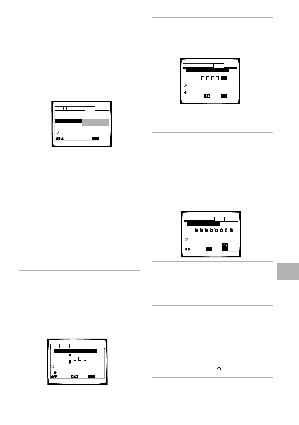
Setting the Parental Lock Level
This changer lets you set the Parental Lock if the DVD
has a parental lock level recorded on it. With Parental
Lock capable discs, you can block access to material you
feel is inappropriate for your children. Refer to the DVD
disc jacket and the accompanying documentation to see
if a particular disc contains a parental lock level.
Make changes to the [Parental Lock] setting in the Setup
screen General menu. Please note that changes to the
Parental Lock level cannot be made when a disc is
playing. Stop playback of the disc before attempting to
make any changes.
Audio1 GeneralLanguageVideo2
Setup Menu Mode
Setup Navigator
Parental Lock
Setup viewing restrictions
Settings: Level Change (For information, refer to
‘Setting the Parental Lock level’ on the
following page.)
Password Change (For information, refer to
‘Changing the password’ on the following
page.)
When a DVD with a set Parental Lock level is
played
Playback cannot be started until the password has been
correctly input by moving the cursor control joystick or
the number buttons, and ENTER has been pressed.
Entering the password
When you select either “Level Change” or “Password
Change”, it is necessary to enter the password (4-digit
code number). Use the following steps at any time you
are asked to enter or confirm your password.
1 Move the cursor control joystick up or down
or the number buttons to select a number
between 0 and 9.
You can also use the number buttons to enter the
numbers directly. When entering your password for
the first time, or changing it, you will be asked to
reenter your password. When using the number
buttons to confirm the password, the numbers
appear as asterisks, and the cursor advances
automatically to the next position.
Move
– Basic
Level Change
Password Change
SETUP
Exit
2 Move the cursor control joystick right or left to
move the cursor to a different position in the
password.
When all four numbers of the password have been
entered, “ENTER” appears on the screen.
Audio1 GeneralLanguageVideo2
Parental Lock: Register Code Number
Return
ENTER
SETUP
Exit
1019
Enter 4–Digit Code
Move
+/–
3 Press ENTER to set the new password.
The password is entered.
Note
Be sure not to forget your password. If you should forget it,
reset the system, and enter a new password. To reset the
system, see ‘Resetting the Changer to System Settings’ (page
75). Please note that this procedure resets the system, and
clears all saved settings, not just the password.
Setting the Parental Lock level
Parental Lock level information should be printed on the
DVD disc jacket or accompanying documentation if it is
featured. Generally speaking, level 8 offers no restriction
on viewing and level 1 provides the strictest viewing
restrictions.
Audio1 GeneralLanguageVideo2
Parental Lock: Level Change
1
234 6785
Level
Set Parental Lock
Move
ENTER
SETUP
Return
ExitSelect
1 Select “Level Change” in the [Parental Lock]
setting and press ENTER.
The screen changes to the password input screen. If
you have not yet set a password, you will be asked
to do so at this time. To enter the password, refer to
‘Entering the password’ on the previous page.
2 Move the cursor control joystick right or left to
adjust the Parental Lock level.
The lock icons appear “unlocked” up to the
selected level to indicate that access is available.
ADVANCED FUNCTIONS
Audio1 GeneralLanguageVideo2
Parental Lock: Register Code Number
––––
Enter 4–Digit Code
Move
+/–
Return
SETUP
Exit
3 Press ENTER to set the new level.
The new Parental Lock level is set and the screen
returns to the General menu screen. To go back to
the General menu screen without making any
changes, press RETURN .
Note
The Condition Memory function can be used to save the Parental
Lock level. Therefore, Parental Lock levels can be set for
individual discs according to their content rather than a set level
for all DVDs.
69
Page 70

Changing the password
Screen Saver – On
External Input – On
Parental Lock – Level 8
Setup Navigator
Background Color
Audio1 GeneralLanguageVideo2
Move
Exit
Blue
Other
Black
SETUP
Setup Menu Mode – Expert
Background Color
Audio1 GeneralLanguageVideo2
–/+
SETUP
Move
Exit
ENTER
Select
Return
Change your password whenever you feel it is
necessary. However, if you forget your existing
password, you cannot enter this screen to change it.
Audio1 GeneralLanguageVideo2
Setup Menu Mode – Basic
Setup Navigator
Parental Lock
Setup viewing restrictions
Move
Level Change
Password Change
ENTER
SETUP
ExitSelect
1 Select “Password Change” in the [Parental
Lock] setting and press ENTER.
The screen changes to the password input screen
as shown in the section ‘Entering the password’ on
the previous page.
2 Enter your current password.
To enter the password, refer to ‘Entering the
password’ on the previous page.
If you have not yet set a password, you cannot
select this setting. Establish a password by
selecting “Level Change” first.
Changing the Background
Color of the Screen
You can select a blue or black background to appear
when the changer is in the stop mode.
Make changes to the [Background Color] setting in the
Setup screen General menu in the “Expert” menu
mode (page 40).
Settings: Black
Blue*
Other
When “Other” is selected
This changer gives you the option of creating your own
background color by adjusting the red, green and blue
levels.
Expert
*Factory setting
3 Move the cursor control joystick or the
number buttons to enter the new password.
4 When the new password has been entered,
press ENTER.
The new password is set and the screen returns to
the General menu screen. To go back to the
General menu screen without making any changes,
press RETURN .
Turning the Screen Saver On
and Off
As a protective function against residual images on the TV
screen or monitor, a phenomenon referred to as “screen
burn”, the screen saver appears when the same screen
has been displayed for a length of time.
Make changes to the [Screen Saver] setting in the Setup
screen General menu in the “Expert” menu mode (page 40).
Expert
Audio1 GeneralLanguageVideo2
Setup Menu Mode – Expert
Setup Navigator
Parental Lock – Level 8
Screen Saver
Background Color -
External Input – Off
Move
On
Off
SETUP
Exit
1 Move the cursor control joystick up or down
to select a color bar.
The selected color bar becomes highlighted.
2 Move the cursor control joystick right or left to
adjust the level of the color.
As the color bar is adjusted, the square on the right
side of the screen indicates how the current mix of
the three colors appears.
3 Repeat steps 1 and 2 until you have achieved
a color that you like.
4 Press ENTER to set the color as the
background color.
Settings: On
70
Off*
*Factory setting
Page 71

Additional
Information
Disc Care
DISC CAUTIONS WHEN USING THIS
CHANGER
• When changing or inserting discs, make sure that the
rack is stopped. Do not attempt to load a disc into the
changer when the rack is moving.
• Never insert more than one disc at a time into one
slot. This can scratch or damage the discs.
• To prevent malfunction, be sure to use an adapter
when loading 8 cm (3 in.) CDs in the changer.
• To prevent malfunction, do not use 8 cm (3 in.) CD
adapters with 8 cm (3 in.) DVDs.
NEVER PLAY CRACKED OR WARPED DISCS
The disc revolves in the changer at high speed when it is
played. Never play a cracked, scratched or warped disc.
This may damage the changer or cause it to malfunction.
NEVER USE DISCS WITH SPECIAL SHAPES
CD’s with special shapes (heart-shaped CDs, octagonal
CDs, etc.) cannot be played on this set.
Attempting to do so may damage the set. Do not use
such CDs.
HOW TO HOLD DISCS
When loading or removing discs, try not to touch their
playing surfaces.
CLEANING
Fingerprints or other dirt on the disc may affect sound
and picture quality.
To clean your discs, use a soft clean cloth to wipe them.
If necessary, moisten a soft cloth with diluted neutral
detergent to remove heavy dirt or fingerprints.
Do not wipe in a circular
direction (Concentric
scratches in the disc groove
tend to cause noise.)
Discs must not be cleaned with record cleaning sprays,
or static prevention sprays, etc. Also do not use volatile
liquids such as benzine, or thinner, etc.
Gently wipe from the
inside toward the outer
edge.
CAUTION WHEN USING THE DISC
All rights reserved.
Unauthorized public performance, broadcasting or
copying is a violation of applicable laws.
Notes on using optical cables
• Do not route cords around sharp angles. When
storing, wind the cords so that they have a diameter
of at least 15 cm (6 in.).
• When connecting, push all the way into the jack.
• Do not use cords with a length of over 3 m (10 ft.).
• If moisture or dust has collected on the plug, wipe it
with a soft cloth before connecting.
15 cm (6 in.)
dia. or more
ADVANCED FUNCTION
/ ADDITIONAL INFORMATION
LENS CLEANER
The changer's pickup lens should not become dirty in
normal use, but if for some reason it should malfunction
due to soiling, contact your nearest Integra authorized
service center. Lens cleaners are commercially available,
however their use is not recommended because some
may cause damage to the lens.
71
Page 72

For Proper and Long Use of
This Unit
DISC RACK CAUTION
D
I
S
C
/
C
H
A
R
A
C
T
E
R
(
P
u
s
h
T
o
E
n
t
e
r
)
Direct Custom
1
2
3
4
5
P
l
a
y
M
o
d
e
R
a
ndom
D
isp
lay
I
n
p
u
t
S
e
a
r
c
h
T
e
x
t
S
t
a
n
d
b
y
S
tandby/O
n
S
i
n
g
l
e
L
o
a
d
e
r
Ac
ce
ss
P
l
a
y
• While changing or inserting discs, be careful not to
press any buttons on the main unit or the remote
controller. The rack may move suddenly, and then
your fingers may be caught between discs in the rack.
• When changing or inserting discs, make sure that the
rack is stopped. Do not attempt to load a disc into the
player when the rack is moving.
• Never insert your hand or any object into the interior.
This can cause a malfunction.
• Never insert more than one disc at a time into one
slot. This can scratch or damage the discs.
• Do not apply force to the rack. This can cause a
malfunction.
6
7
8
9
A
u
dio
/ Vi
deo
U
p
d
a
t
e
C
le
a
r
1
0
O
p
e
n
/
C
l
o
s
e
Stop
Play
P
a
u
s
e
K
e
y
b
o
a
r
d
/
M
o
u
s
e
DPT-1
DO NOT BLOCK VENTS
Do NOT use the changer on top of a long-fibered carpet,
bed or sofa, and do not cover it with a cloth, etc. This
will prevent heat radiation and could result in damage.
AVOID HEAT
Do NOT place the unit on equipment which generates
heat, such as an amplifier.
When installing the unit in a rack, place it on the lowest
shelf possible (however, not where it is exposed to dust)
and separated from the amplifier to avoid the heat
generated by the amplifier or other audio equipment.
CONDENSATION
Moisture may form in the operating section of the
changer if the changer is brought from cool surroundings
into a warm room or if the temperature of the room rises
suddenly. When this happens, the changer’s
performance will be impaired.
To prevent this, let the changer stand in its new
surroundings for about an hour before switching it on, or
make sure that the room temperature rises gradually.
Condensation may also form during the summer if the
changer is exposed to the breeze from an air conditioner.
In such cases, change the location of the changer.
DO NOT MOVE THE UNIT WHEN DISCS ARE
LOADED IN THE RACK
Moving the changer when discs are loaded may damage
the discs and may cause the changer to malfunction.
WHEN MOVING THE UNIT
When changing places of installation or packing the unit
for moving, be sure to remove all of the discs from the
rack and close the changer’s hood. Then, press
Standby/On and switch the power to standby. Check
that the “–Off–” indication on the display goes off,
then disconnect the power cord. Moving this unit with
the disc rack loaded may result in damage to this unit.
INSTALLATION
• Select a stable place to the side of a TV set or stereo
system to be connected to the unit.
• When using the unit with a stereo system, install the
speakers a little bit away from the TV.
• Do NOT install the unit on top of a TV or color monitor.
Install the unit away from equipment that may be
affected by magnetism, such as a cassette deck.
• Do NOT place objects on top of the unit.
AVOID INSTALLING IN A PLACE THAT IS:
• Exposed to direct sunlight
• Exposed to humidity or where ventilation is poor
• Extremely hot or cold
• Exposed to vibration
• Exposed to dust
• Exposed to oily smoke, steam or heat (for example, a
kitchen)
72
SWITCH POWER TO STANDBY WHEN NOT
USING THE UNIT
Depending on the strength of the TV or radio broadcast
signal, having the TV or radio on while power to the unit
is on may result in stripes on the TV screen or noise.
However, this is not a malfunction of this unit or the TV
or radio. In such a case, switch the power of the unit to
standby.
POWER-CORD CAUTION
Handle the power cord by the plug. Do not pull out the
plug by tugging the cord and never touch the power cord
when your hands are wet as this could cause a short
circuit or electric shock. Do not place the unit, a piece of
furniture, etc., on the power cord, or pinch the cord.
Never make a knot in the cord or tie it with other cords.
The power cords should be routed in such a way that
they are not likely to be stepped on. A damaged power
cord can cause a fire or give you an electrical shock.
Check the power cord once in a while. When you find it
damaged, ask your nearest Integra authorized service
center or your dealer for a replacement.
Page 73

Language Code List
Language codes are used when setting the audio and
subtitle language preferences (page 47).
Language Input-code
Japanese (ja)
English (en)
French (fr)
German (de)
Italian (it)
Spanish (es)
Dutch (nl)
Russian (ru)
Chinese (zh)
Korean (ko)
Greek (el)
Afar (aa)
Abkhazian (ab)
Afrikaans (af)
Amharic (am)
Arabic (ar)
Assamese (as)
Aymara (ay)
Azerbaijani (az)
Bashkir (ba)
Byelorussian (be)
Bulgarian (bg)
Bihari (bh)
Bislama (bi)
Bengali (bn)
Tibetan (bo)
Breton (br)
Catalan (ca)
Corsican (co)
Czech (cs)
Welsh (cy)
Danish (da)
Bhutani (dz)
Esperanto (eo)
Estonian (et)
Basque (eu)
Persian (fa)
Finnish (fi)
Fiji (fj)
Faroese (fo)
Frisian (fy)
Irish (ga)
Scots-Gaelic (gd)
Galician (gl)
Guarani (gn)
Gujarati (gu)
Hausa (ha)
1001
0514
0618
0405
0920
0519
1412
1821
2608
1115
0512
0101
0102
0106
0113
0118
0119
0125
0126
0201
0205
0207
0208
0209
0214
0215
0218
0301
0315
0319
0325
0401
0426
0515
0520
0521
0601
0609
0610
0615
0625
0701
0704
0712
0714
0721
0801
Language Input-code
Hindi (hi)
Croatian (hr)
Hungarian (hu)
Armenian (hy)
Interlingua (ia)
Interlingue (ie)
Inupiak (ik)
Indonesian (in)
Icelandic (is)
Hebrew (iw)
Yiddish (ji)
Javanese (jw)
Georgian (ka)
Kazakh (kk)
Greenlandic (kl)
Cambodian (km)
Kannada (kn)
Kashmiri (ks)
Kurdish (ku)
Kirghiz (ky)
Latin (la)
Lingala (ln)
Laothian (lo)
Lithuanian (lt)
Latvian (lv)
Malagasy (mg)
Maori (mi)
Macedonian (mk)
Malayalam (ml)
Mongolian (mn)
Moldavian (mo)
Marathi (mr)
Malay (ms)
Maltese (mt)
Burmese (my)
Nauru (na)
Nepali (ne)
Norwegian (no)
Occitan (oc)
Oromo (om)
Oriya (or)
Panjabi (pa)
Polish (pl)
Pashto, Pushto (ps)
Portuguese (pt)
Quechua (qu)
Rhaeto-Romance (rm)
0809
0818
0821
0825
0901
0905
0911
0914
0919
0923
1009
1023
1101
1111
1112
1113
1114
1119
1121
1125
1201
1214
1215
1220
1222
1307
1309
1311
1312
1314
1315
1318
1319
1320
1325
1401
1405
1415
1503
1513
1518
1601
1612
1619
1620
1721
1813
Language Input-code
Kirundi (rn)
Romanian (ro)
Kinyarwanda (rw)
Sanskrit (sa)
Sindhi (sd)
Sangho (sg)
Serbo-Croatian (sh)
Singhalese (si)
Slovak (sk)
Slovenian (sl)
Samoan (sm)
Shona (sn)
Somali (so)
Albanian (sq)
Serbian (sr)
Siswati (ss)
Sesotho (st)
Sundanese (su)
Swedish (sv)
Swahili (sw)
Tamil (ta)
Telugu (te)
Tajik (tg)
Thai (th)
Tigrinya (ti)
Turkmen (tk)
Tagalog (tl)
Setswana (tn)
Tonga (to)
Turkish (tr)
Tsonga (ts)
Tatar (tt)
Twi (tw)
Ukrainian (uk)
Urdu (ur)
Uzbek (uz)
Vietnamese (vi)
Volapük (vo)
Wolof (wo)
Xhosa (xh)
Yoruba (yo)
Zulu (zu)
1814
1815
1823
1901
1904
1907
1908
1909
1911
1912
1913
1914
1915
1917
1918
1919
1920
1921
1922
1923
2001
2005
2007
2008
2009
2011
2012
2014
2015
2018
2019
2020
2023
2111
2118
2126
2209
2215
2315
2408
2515
2621
ADDITIONAL INFORMATION
73
Page 74

Troubleshooting
Incorrect operations are often mistaken for trouble and
malfunctions. If you think that there is something wrong
with this component, check the points below.
Sometimes the trouble may lie in another component.
Inspect the other components and electrical appliances
being used. If the trouble cannot be rectified even after
exercising the checks listed below, ask your nearest
Integra authorized service center or your dealer to carry
out repair work.
The hood opens automatically.
The disc is dirty or warped.
\ Refer to “Disc Care” (page 71).
The disc has been loaded in the rack incorrectly.
\ Check that the disc has been loaded with the label
side facing the left. (When loading double-sided
DVDs, load the disc in the rack with the label
denoting the contents you want to view facing the
right.)
DVD region number does not conform with this unit.
\ If the region number on the DVD does not match
the number on the changer, the DVD cannot be
used (page 77).
There is condensation on the operating section of the
changer.
\ Allow time for condensation to evaporate. If
changer is near an air conditioning unit, you should
move the changer (page 72).
Settings are canceled.
When the power is turned off by power failure or by
unplugging the power cord, settings will be canceled.
\ Before unplugging the power cord, press
POWER on the remote controller checking that
“--OFF--” disappears in the display.
No picture.
Connection is incorrect.
\ Check that cord connections are correct and that
plugs are firmly connected.
Changer settings are incorrect.
\ Check that VIDEO SELECT is set firmly in the
correct position.
Operation (settings) of TV or AV component is not
appropriate.
\ Be sure that your TV or AV component is set up to
view DVD playback.
External input settings are incorrect.
\ Check that the power of the component to be
used for external video input has been turned on.
\ Check that the Setup screen General menu
“External Input” setting is correct (page 68).
The screen is stretched or aspect does not change.
The multi aspect setting is not appropriate.
\ Change the aspect setting in the [TV Screen]
setting in the Setup screen Video menu to the
screen type most appropriate to the TV or monitor
you are using (page 43).
mark appears on screen.
The selected function does not operate for that disc.
mark appears on screen.
The operation is prohibited by the changer.
Picture playback stops and the operation buttons
cannot be used.
\ Stop disc playback (press STOP 7), then start
playback again.
\ Press Standby/On on the front panel to turn
the changer off, and then turn the power back on
again.
New settings made in the Setup screen menus while
a disc is playing are ineffective.
Some settings can be changed while a disc is playing,
but are not effective. This is not a malfunction.
\ Make the same setting when the changer is
stopped.
\ Stop disc playback (press STOP 7), then start
playback again. When playback is resumed, the
new settings should be in effect. Please note that
making settings in the Setup screen menus may
cancel the resume function.
When making changes in the Setup screen menus,
is displayed.
There is a Video CD or CD loaded in the changer and
the setting that was changed only applies to DVD
performance.
\ The settings will be effective the next time a DVD
is loaded.
74
The screen is suddenly squeezed when the Setup
screen is opened.
If the Setup screen is opened during playback of a
DVD being viewed in the letter box format, the screen
may switch to the wide screen format.
\ This is not a malfunction. The screen will return to
normal when the Setup screen is closed.
Picture disturbance during playback or dark.
This changer is compatible with Macro-Vision System
copy guard. Some discs include a copy prevention
signal, and when this type of disc is played back,
stripes etc., may appear on some sections of the
picture depending on the TV.
\ This is not a malfunction.
Discs respond differently to particular changer
functions which may result in the screen becoming
black for a brief instant or shaking slightly when the
function is executed.
\ These problems are largely due to differences
between discs and disc content and are not
malfunctions of this changer.
When recorded on a VCR or passed through an AV
selector, there is disturbance in the playback picture.
This is not a malfunction.
\ Due to the changer’s copy protection circuits,
connection of this device through a VCR or an AV
selector may prevent recording or cause picture
problems.
Page 75

Remote control operation is not possible.
The remote controller is too far from the changer, or
the angle with the remote sensor is too wide.
\ Be sure to operate the remote from a location
within its operating range (page 8).
The batteries are exhausted.
\ Replace the exhausted batteries with all new
batteries (page 8).
The remote controller supplied with an Integra
receiver does not work with the changer.
\ The remote controller supplied with your Integra
receiver will not work with this changer. If you
have a receiver remote controller that is equipped
with the learning function, program the functions
from the supplied remote controller to your
receiver remote controller.
Audio is not output or is distorted.
The Setup screen Audio 1 menu [96 kHz PCM Out]
setting is set to “96 kHz”.
\ On DVDs that contain copy protection, it may not
be possible to play back the audio at 96 kHz.
When this type of disc is encountered, even if “96
kHz” is selected, the changer automatically
outputs the digital audio output at a compressed
rate of 48 kHz. This is not a malfunction.
\ The “4:3 (Letter Box)” screen setting is selected.
Even if “96 kHz” is selected, the changer
automatically downsamples the audio to a
compressed rate of 48 kHz. This is not a malfunction.
\ Be sure to make analog audio connections as well
as digital connections (page 17).
The disc is dirty.
\ Refer to “Disc Care” (page 71).
The connection plugs are not inserted fully into the
terminals or are not connected.
\ Check that all connection plugs are firmly inserted.
The connection plug or terminal is dirty.
\ Check that the plugs and terminals are wiped
clean of dirt, etc.
Audio cable connection is wrong.
\ Check to make sure that the audio cables are
connected correctly (page 17).
Connection is made to the stereo amplifier‘s PHONO
input terminal.
\ Change connection to any input terminal except
PHONO.
The pause mode is engaged.
\ Press PLAY 3 or PAUSE 8 to exit the pause
mode.
Stereo amplifier operation is incorrect.
\ Check input (CD, AUX, etc.) selector to determine
if it is selected for DVD playback.
External input settings are incorrect.
\ Check that the power of the component to be
used for external audio input has been turned on.
\ Check that the Setup screen General menu
“External Input” setting is correct (page 68).
The DTS audio soundtrack on a DVD has been
selected.
\ There is no audio output from the analog jacks
during DTS audio playback. Select another
soundtrack.
Noticeable difference in DVD and CD volume.
DVDs and CDs use different recording methods.
\ This is not a malfunction.
There is no video and/or audio output from a SLAVE
DPT-1 or other component connected to the input
jacks on this unit.
Connections are incorrect.
\ Check that connections are made firmly from the
output jacks on the other component to the IN
jacks on this unit (pages 66 and 67).
Menu settings are incorrect
\ Check that the Setup screen Other menu [External
Input] setting is set appropriately (page 68).
The SLAVE DPT-1 does not operate when connected
Connections are incorrect.
\ Check that the control cable is connected to the
MASTER jack on this unit and the SLAVE jack on
the connected DPT-1 (page 66).
\ When connections are not made correctly or
transmission cannot be performed between the
Master and Slave player, "CONNECT ERR" is
displayed in the display window. If this message
is displayed, connect the cord correctly (page 66).
Caution
Static electricity or other external influence may cause
malfunctioning of this unit. In this case, unplugging
the power cord and then re-plugging it in will usually
reset the unit for proper operation. If this does not
correct the problem, please consult your nearest
Integra service center.
Resetting the Changer to
System Settings
To reset the changer, press and hold Stop on the front
panel when pressing Standby/On on the front panel
to turn the unit from standby to on.
All input text data, program memory, saved settings
from functions such as Function Memory and
Condition Memory are cleared, and all Setup screen
menus are returned to factory settings.
ADDITIONAL INFORMATION
75
Page 76

Term s
Aspect ratio
Aspect ratio refers to the length to height ratio of TV
screens. The ratio of a standard TV is 4:3, while the ratio
of a high-definition or wide TV is 16:9. The latter allows
you to enjoy a picture with a wider perspective.
Digital output (Optical)
Normally, audio is converted to an electric signal and
transmitted through an electric wire from the changer to
the amplifier, etc. Changing this signal to a digital signal
and transmitting it through an fiber-optic cable is called
optical digital output. Similarly, optical digital input
receives digital signals from external units such as an AV
amplifier or receiver.
CD TEXT
CD TEXT is a system in which text information is stored
on a CD. CD TEXT can be used to display the disc’s title,
the artist's name, and track titles as well as other
information. Additionally, this changer uses the CD TEXT
already on the CD when the discs are updated in the
changer.
Chapter number
Chapter numbers are the numbers assigned to sections
of a title on the disc, similar to chapters in a book. If the
disc includes chapter numbers, you can locate the
section you want very quickly using search and other
functions.
Component (color difference) video output
The color signal of the TV is divided into the luminance
(Y) signal and the color (PB and PR) signals and then
output. In this way mutual interference of each signal is
avoided. On a TV with component input jacks, these
signals are synthesized to produce the picture.
Condition memory
“Condition” refers to the various mode settings, etc. On
this changer, various conditions, such as those set
during playback, can be memorized. This function allows
you to play back the same disc at any time without
having to redo your preferred settings.
Digital bitstream
The bitstream does not refer to the audio signal, but
rather to the digital data that, once converted, becomes
the audio signal. The changer outputs digital bitstreams
via the digital optical or digital coaxial output. If the
bitstream cannot be decoded by the connected AV
amplifier etc., digital noise is produced. Digital bitstream
formats compatible with different entertainment
systems can be selected in the Setup screen Audio 1
menu.
Digital output (Coaxial)
Output of the digital audio signal is transmitted
electronically using a coaxial cable. Because the signal
being transmitted is digital, connection must be made to
the coaxial digital input of another component. Noise will
be output if connected to the analog audio inputs as the
digital signal cannot be decoded.
DNR (Digital Noise Reduction)
Digital noise reduction, in reference to video picture
quality, refers to the detection and removal of digital
artifacts, or errant video data, which appear as specks on
the screen. When the digital noise reduction function of
this changer is on, some of this data can be detected
and kept from appearing on the screen.
Dolby Digital
Using a maximum of 5.1 channels of audio, this high
quality surround system (Surround Digital) is used in
many of the finer movie theaters around the world.
In order to enjoy Dolby Digital discs, this unit’s digital
output jack (either coaxial or optical) must be connected
to the digital input jack of an AV amplifier or Dolby Digital
decoder to enjoy the sound of Dolby Digital soundtracks.
DTS
DTS stands for Digital Theater System. DTS is a
surround system different from Dolby Digital that has
become a popular surround sound format for movies.
In order to enjoy the benefits of DTS encoded discs, the
digital output jack (either coaxial or optical) of this
changer needs to be connected to an AV amplifier or
receiver or to a DTS decoder to be able to enjoy the
surround sound of DTS audio. DTS audio is not output
from the analog audio outputs.
Dynamic range
Dynamic range refers to the difference between the
maximum and minimum levels of the audio soundtrack
as measured in decibels (dB).
Compressing the dynamic range raises the minimum
signal level and lowers the maximum signal level. This
allows you to hear voices and other low level audio
signals clearly while lowering strong audio signals like
the sound of explosions.
Function Memory
Function Memory lets you make a shortcut list of up to
five regularly used settings from the Setup screen page.
By selecting a function from the Function Memory
window, the appropriate Setup screen menu and
function are automatically opened.
76
Page 77

MASTER-SLAVE CONTROL
MASTER-SLAVE control refers to two identical units
connected together for joint control. The first changer
(Master) receives remote control signals for both units
and controls the disc selection, audio and video output,
and information displays of the second changer (Slave).
MPEG
Short for Moving Picture Experts Group. This is an
international standard for compression of moving
images. On some DVDs, digital audio has been
compressed and recorded in this format.
Multi-angle
In a TV or movie studio, a single image is usually filmed
by more than one camera at the same time, and one of
those images is selected by the program director and
transmitted to your TV. Some DVD discs are recorded
with the angles of more than one camera used for
filming, and these can be selected using this changer.
These types of discs are called multi-angle discs.
Multi-Language Subtitle
Subtitles are language titles superimposed on movies, or
other media. Up to 32 different subtitle languages can
be recorded on a DVD disc. The subtitle function can be
used to select the language of your choice.
Multiple Language
The Multiple Language feature refers to the actual audio
language that you hear while enjoying DVD playback. Up
to 8 different language tracks can be recorded on a DVD.
The Multiple Language function can be used to select
the audio language of your choice.
Regional restriction codes (region number)
Regional restriction codes are built in to DVD players and
DVD discs for each sales region. If the regional code of
the DVD player does not match one of the regional
codes of the DVD disc, playback is not possible.
The region number can be found on the rear panel of the
DVD player. The illustration below shows the regions
and corresponding region numbers.
Sampling Frequency
When a sound wave is converted to a digital signal, the
sound is sampled and converted to data at a specific
frequency rate. For example, a signal with a 96 kHz
sampling rate indicates that in one second, the analog
signal was sampled 96000 times to produce the digital
signal.
S-video
Connecting the S-video output on the changer to a TV or
monitor with S-video input via an S-video cable produces
clearer picture reproduction by sending separate signals
for the luminance and the color. These signals are then
combined by the television to produce a better quality
picture.
Parental lock level
This function was suggested by parents concerned
about what type of media their children were able to
watch. Parental lock restrictions are restrictions
incorporated into titles which include scenes that
parents may not wish their children to view.
PBC (Playback Control)
This refers to signals recorded on a Video CD (Version
2.0) enabling playback control. You can use menus
recorded on discs with PBC for easy, interactive search
for desired scenes, and playback. You can also enjoy
viewing high-resolution/standard resolution still images.
PCM
PCM stands for Pulse Code Modulation and is digital
audio. The digital audio of CDs is PCM. This changer also
has a function that converts Dolby Digital and MPEG
digital bitstreams into PCM to enable you to listen to
quality digital sound even without a special decoder.
ADDITIONAL INFORMATION
77
Page 78

Specifications
General
System ..........................
Power requirements ............................. AC 120 V, 60 Hz
Power consumption ................................................ 21 W
Power consumption in standby mode .... less than 0.9 W
Weight ................................................. 7.8 kg (17.21 bs.)
Dimensions ................... 435 (W) x 441 (D) x 193 (H) mm
Operating temperature ... +5°C to +35°C
Operating humidity .......... 5% to 85% (no condensation)
S-Video input/output
Y (luminance) - Output level ........................1 Vp-p (75 Ω)
C (color) - Output level ........................ 286 mVp-p (75 Ω)
Jacks .......................................................... S-VIDEO jack
Video input/output
Output level ................................................1 Vp-p (75 Ω)
Jacks ................................................................. RCA jack
File-type DVD system and Compact
Disc digital audio system
17 1/18“ x 17 3/8“ x 71 5/8“
(Not including protruding cables, etc.)
(+36°F to +96°F)
Digital output
Optical digital output ........................... Optical digital jack
Coaxial digital input/output ................................ RCA jack
Control jack
MASTER-SLAVE ..................................... Minijack (3.5 ø)
Other jack
KEYBOARD/MOUSE jack ....... 6-pin DIN connection jack
Accessories
Remote controller .......................................................... 1
AA (R6P) dry cell batteries ............................................. 2
Audio cord ......................................................................1
Video cord ......................................................................1
Master-Slave control cord .............................................. 1
Note
The specifications and design of this product are subject to
change without notice, due to improvement.
Component video output
(Y, PB, PR)
Output level ......................................... Y: 1.0 Vp-p (75 Ω)
PB, PR: 0.7 Vp-p (75 Ω)
Jacks ................................................................. RCA jack
Audio input/output
Output level
During audio output ............. 200 mVrms (1 kHz, –20 dB)
Number of channels ....................................................... 2
Jacks ................................................................. RCA jack
Digital audio characteristics
Frequency response ..... 4 Hz to 44 kHz (DVD fs: 96 kHz)
S/N ratio .............................................. more than 115 dB
Dynamic range .................................... more than 102 dB
Total harmonic distortion .................................... 0.002%
Wow and flutter ............................ Limit of measurement
(±0.001% W. PEAK) or lower
78
Page 79

I
C
N
I
D
N
U
O
S
R
T
T
R
C
I
E
E
L
S
E
EIA
•
•
EST 1924
A
N
S
O
S
I
O
T
C
A
I
We
Want You
LISTENING
For A Lifetime
Selecting fine audio equipment such as the unit you’ve just
purchased is only the start of your musical enjoyment. Now
it’s time to consider how you can maximize the fun and
excitement your equipment offers. This manufacturer and
the Electronic Industries Association’s Consumer Electronics
Group want you to get the most out of your equipment by
playing it at a safe level. One that lets the sound come through
loud and clear without annoying blaring or distortion-and,
most importantly, without affecting your sensitive hearing.
Sound can be deceiving. Over time your hearing “comfort
level” adapts to higher volumes of sound. So what sounds
“normal” can actually be loud and harmful to your hearing.
Guard against this by setting your equipment at a safe level
BEFORE your hearing adapts.
To establish a safe level:
• Start your volume control at a low setting.
• Slowly increase the sound until you can hear it comfortably
and clearly, and without distortion.
Once you have established a comfortable sound level:
• Set the dial and leave it there.
Taking a minute to do this now will help to prevent hearing
damage or loss in the future. After all, we want you listening
for a lifetime.
We Want You Listening For A
Lifetime
Used wisely, your new sound equipment will provide a
lifetime of fun and enjoyment. Since hearing damage from
loud noise is often undetectable until it is too late, this
manufacturer and the Electronic Industries Association’s
Consumer Electronics Group recommend you avoid prolonged
exposure to excessive noise. This list of sound levels is
included for your protection.
Decibel
Level Example
30 Quiet library, soft whispers
40 Living room, refrigerator, bedroom away from traffic
50 Light traffic, normal conversation, quiet office
60 Air conditioner at 20 feet, sewing machine
70 Vacuum cleaner, hair dryer, noisy restaurant
80 Average city traffic, garbage disposals, alarm clock
at two feet.
THE FOLLOWING NOISES CAN BE
DANGEROUS UNDER CONSTANT EXPOSURE
90 Subway, motorcycle, truck traffic, lawn mower
100 Garbage truck, chain saw, pneumatic drill
120 Rock band concert in front of speakers, thunderclap
140 Gunshot blast, jet plane
180 Rocket launching pad
Information courtesy of the Deafness Research Foundation.
I
C
N
I
D
N
U
O
S
R
T
T
R
C
I
E
E
L
S
E
EIA
•
•
EST 1924
A
N
S
O
S
I
O
T
C
A
I
We
Want You
LISTENING
For A Lifetime
79
Page 80

Integra Division of
ONKYO U.S.A. CORPORATION
200 Williams Drive, Ramesy, N.J. 07446, U.S.A.
Tel: 201-825-7950 Fax: 201-825-8150 E-mail: integra@onkyousa.com
Integra Division of
ONKYO CORPORATION
Sales & Product Planning Div. : 2-1, Nisshin-cho, Neyagawa-shi,
OSAKA 572-8540, JAPAN
Tel: 072-831-8111 Fax: 072-833-5222
HOMEPAGE
http://www.onkyo.co.jp/
SN 29342879
<VRB1249-A>
Printed in Japan
D0002-1
E
 Loading...