

Integra DHC-80.2 Owner's Manual

AV Controller
DHC-80.2
Instruction Manual
Introduction
G
WARNING:
TO REDUCE THE RISK OF FIRE OR ELECTRIC
SHOCK, DO NOT EXPOSE THIS APPARATUS TO
RAIN OR MOISTURE.
CAUTION:
TO REDUCE THE RISK OF ELECTRIC SHOCK,
DO NOT REMOVE COVER (OR BACK). NO
USER-SERVICEABLE PARTS INSIDE. REFER
SERVICING TO QUALIFIED SERVICE
PERSONNEL.
Important Safety Instructions
1. Read these instructions.
2. Keep these instructions.
3. Heed all warnings.
4. Follow all instructions.
5. Do not use this apparatus near water.
6. Clean only with dry cloth.
7. Do not block any ventilation openings. Install in
accordance with the manufacturer’s instructions.
8. Do not install near any heat sources such as radiators,
heat registers, stoves, or other apparatus (including
amplifiers) that produce heat.
9. Do not defeat the safety purpose of the polarized or
grounding-type plug. A polarized plug has two blades
with one wider than the other. A grounding type plug
has two blades and a third grounding prong. The wide
blade or the third prong are provided for your safety. If
the provided plug does not fit into your outlet, consult
an electrician for replacement of the obsolete outlet.
10. Protect the power cord from being walked on or
pinched particularly at plugs, convenience receptacles,
and the point where they exit from the apparatus.
11. Only use attachments/accessories specified by the
manufacturer.
12. Use only with the cart, stand,
tripod, bracket, or table specified by the manufacturer, or
sold with the apparatus. When
a cart is used, use caution
when moving the cart/apparatus combination to avoid
injury from tip-over.
13. Unplug this apparatus during lightning storms or when
unused for long periods of time.
14. Refer all servicing to qualified service personnel. Servicing is required when the apparatus has been damaged in any way, such as power-supply cord or plug is
damaged, liquid has been spilled or objects have fallen
into the apparatus, the apparatus has been exposed to
rain or moisture, does not operate normally, or has
been dropped.
PORTABLE CART WARNIN
S3125A
WARNING
RISK OF ELECTRIC SHOCK
DO NOT OPEN
The lightning flash with arrowhead symbol, within an
equilateral triangle, is intended to alert the user to the
presence of uninsulated “dangerous voltage” within
the product’s enclosure that may be of sufficient
magnitude to constitute a risk of electric shock to
persons.
The exclamation point within an equilateral triangle is
intended to alert the user to the presence of important
operating and maintenance (servicing) instructions in
the literature accompanying the appliance.
AVIS
RISQUE DE CHOC ELECTRIQUE
NE PAS
OUVRIR
15. Damage Requiring Service
Unplug the apparatus from the wall outlet and refer
servicing to qualified service personnel under the following conditions:
A. When the power-supply cord or plug is damaged,
B. If liquid has been spilled, or objects have fallen
into the apparatus,
C. If the apparatus has been exposed to rain or water,
D. If the apparatus does not operate normally by fol-
lowing the operating instructions. Adjust only
those controls that are covered by the operating
instructions as an improper adjustment of other
controls may result in damage and will often
require extensive work by a qualified technician to
restore the apparatus to its normal operation,
E. If the apparatus has been dropped or damaged in
any way, and
F. When the apparatus exhibits a distinct change in
performance this indicates a need for service.
16. Object and Liquid Entry
Never push objects of any kind into the apparatus
through openings as they may touch dangerous voltage points or short-out parts that could result in a fire
or electric shock.
The apparatus shall not be exposed to dripping or
splashing and no objects filled with liquids, such as
vases shall be placed on the apparatus.
Don’t put candles or other burning objects on top of
this unit.
17. Batteries
Always consider the environmental issues and follow
local regulations when disposing of batteries.
18. If you install the apparatus in a built-in installation,
such as a bookcase or rack, ensure that there is adequate ventilation.
Leave 20 cm (8") of free space at the top and sides and
10 cm (4") at the rear. The rear edge of the shelf or
board above the apparatus shall be set 10 cm (4")
away from the rear panel or wall, creating a flue-like
gap for warm air to escape.
En
2

Precautions
1. Recording Copyright—Unless it’s for personal use
only, recording copyrighted material is illegal without
the permission of the copyright holder.
2. AC Fuse—The AC fuse inside the unit is not user-serviceable. If you cannot turn on the unit, contact the
dealer from whom you purchased this unit.
3. Care—Occasionally you should dust the unit all over
with a soft cloth. For stubborn stains, use a soft cloth
dampened with a weak solution of mild detergent and
water. Dry the unit immediately afterwards with a
clean cloth. Don’t use abrasive cloths, thinners, alcohol, or other chemical solvents, because they may
damage the finish or remove the panel lettering.
4. Power
WARNING
BEFORE PLUGGING IN THE UNIT FOR THE
FIRST TIME, READ THE FOLLOWING SECTION
CAREFULLY.
AC outlet voltages vary from country to country.
Make sure that the voltage in your area meets the voltage requirements printed on the unit’s rear panel (e.g.,
AC 230 V, 50 Hz or AC 120 V, 60 Hz).
The power cord plug is used to disconnect this unit
from the AC power source. Make sure that the plug is
readily operable (easily accessible) at all times.
Pressing On/Standby to select Standby mode does
not fully shutdown the unit. If you do not intend to use
the unit for an extended period, remove the power cord
from the AC outlet.
5. Preventing Hearing Loss
Caution
Excessive sound pressure from earphones and headphones can cause hearing loss.
6. Batteries and Heat Exposure
War nin g
Batteries (battery pack or batteries installed) shall not
be exposed to excessive heat as sunshine, fire or the
like.
7. Never Touch this Unit with Wet Hands—Never handle this unit or its power cord while your hands are
wet or damp. If water or any other liquid gets inside
this unit, have it checked by the dealer from whom
you purchased this unit.
8. Handling Notes
• If you need to transport this unit, use the original
packaging to pack it how it was when you originally
bought it.
• Do not leave rubber or plastic items on this unit for
a long time, because they may leave marks on the
case.
• This unit’s top and rear panels may get warm after
prolonged use. This is normal.
• If you do not use this unit for a long time, it may not
work properly the next time you turn it on, so be
sure to use it occasionally.
For U.S. models
FCC Information for User
CAUTION:
The user changes or modifications not expressly approved
by the party responsible for compliance could void the
user’s authority to operate the equipment.
NOTE:
This equipment has been tested and found to comply with
the limits for a Class B digital device, pursuant to Part 15
of the FCC Rules. These limits are designed to provide
reasonable protection against harmful interference in a
residential installation.
This equipment generates, uses and can radiate radio frequency energy and, if not installed and used in accordance
with the instructions, may cause harmful interference to
radio communications. However, there is no guarantee
that interference will not occur in a particular installation.
If this equipment does cause harmful interference to radio
or television reception, which can be determined by turning the equipment off and on, the user is encouraged to try
to correct the interference by one or more of the following
measures:
• Reorient or relocate the receiving antenna.
• Increase the separation between the equipment and
receiver.
• Connect the equipment into an outlet on a circuit different from that to which the receiver is connected.
• Consult the dealer from whom you purchased this unit or
an experienced radio/TV technician for help.
For Canadian Models
NOTE: THIS CLASS B DIGITAL APPARATUS COM-
PLIES WITH CANADIAN ICES-003.
For models having a power cord with a polarized plug:
CAUTION: TO PREVENT ELECTRIC SHOCK,
MATCH WIDE BLADE OF PLUG TO WIDE SLOT,
FULLY INSERT.
Modèle pour les Canadien
REMARQUE: CET APPAREIL NUMÉRIQUE DE
LA CLASSE B EST CONFORME À LA NORME
NMB-003 DU CANADA.
Sur les modèles dont la fiche est polarisée:
ATTENTION: POUR ÉVITER LES CHOCS ÉLEC-
TRIQUES, INTRODUIRE LA LAME LA PLUS LARGE
DE LA FICHE DANS LA BORNE CORRESPONDANTE DE LA PRISE ET POUSSER JUSQU’AU
FOND.
En
3
Thank you for purchasing an Integra AV controller.
Please read this manual thoroughly before making connections and plugging in the unit.
Following the instructions in this manual will enable you
to obtain optimum performance and listening enjoyment
from your new AV controller.
Please retain this manual for future reference.
Supplied Accessories
Make sure you have the following accessories:
Indoor FM antenna (➔ 22)
AM loop antenna (➔ 22)
Power cord (➔ 22)
Speaker setup microphone (➔ 30)
Remote controller and two batteries (AA/R6)
*
In catalogs and on packaging, the letter at the end of the product name indicates the color. Specifications and operations are
the same regardless of color.
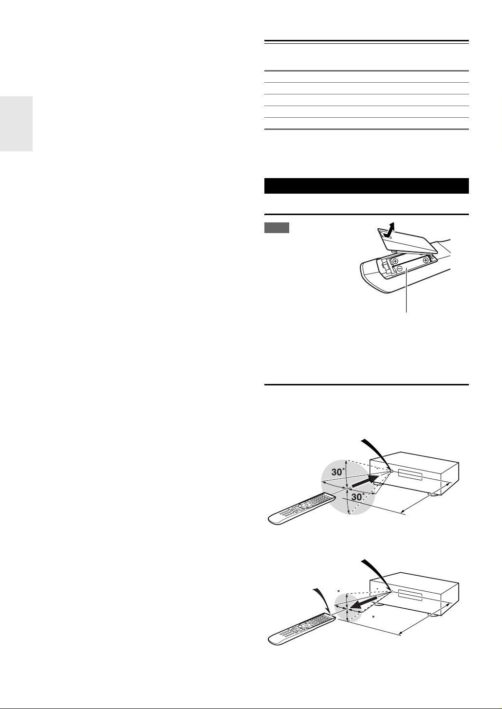
Using the Remote Controller
Installing the Batteries
Note
• If the remote controller
doesn’t work reliably, try
replacing the batteries.
• Don’t mix new and old
batteries or different
types of batteries.
• If you intend not to use
the remote controller for
a long time, remove the
batteries to prevent damage from leakage or corrosion.
• Remove expired batteries as soon as possible to prevent damage
from leakage or corrosion.
Batteries (AA/R6)
Aiming the Remote Controller
To use the remote controller, point it at the AV controller’s
remote control sensor, as shown below.
Transmission
Remote control sensor
AV controller
Approx. 16 ft. (5 m)
Received
Transmitter
AV controller
Incoming sensor
15
15
Approx. 16 ft. (5 m)
En
4
Contents
Introduction
Important Safety Instructions ......................................... 2
Precautions....................................................................... 3
Supplied Accessories...................................................... 4
Using the Remote Controller .......................................... 4
Features ............................................................................ 6
Front & Rear Panels......................................................... 8
Front Panel..................................................................... 8
Display............................................................................ 9
Rear Panel ................................................................... 10
Remote Controller.......................................................... 11
Controlling the AV Controller........................................ 11
About Home Theater...................................................... 12
Enjoying Home Theater................................................ 12
Connections
Connecting the AV Controller....................................... 13
Connecting Your Speakers .......................................... 13
About AV Connections ................................................. 18
Connecting Your Components with HDMI.................... 19
Connecting Your Components ..................................... 20
Connecting Integra/Onkyo u Components ................ 21
Connecting Antenna..................................................... 22
Connecting the Power Cord ......................................... 22
Which Connections Should I Use?............................... 23
Turning On & Basic Operations
Turning On/Off the AV Controller ................................. 25
Turning On ................................................................... 25
Turning Off ................................................................... 25
Basic Operations............................................................ 26
Selecting the Language Used for
the Onscreen Setup Menus ....................................... 26
Playing the Connected Component.............................. 26
Displaying Source Information ..................................... 26
Setting the Display Brightness ..................................... 26
Muting the AV Controller .............................................. 27
Using the Sleep Timer.................................................. 27
Using the Home Menu.................................................. 27
Changing the Input Display .......................................... 28
Using Headphones....................................................... 28
Using Activities to Start Easy Macros........................... 28
Audyssey MultEQ
Room Correction and Speaker Setup ........................ 29
Listening to the Radio ................................................... 32
Using the Tuner............................................................ 32
Presetting FM/AM Stations........................................... 33
Listening to SIRIUS Satellite Radio
(North American models)........................................... 33
Using RDS (Australian models).................................... 39
Recording ....................................................................... 41
Using the Listening Modes ........................................... 42
Selecting Listening Modes ........................................... 42
About Listening Modes................................................. 43
®
XT32
®
Advanced Operations
Advanced Setup .............................................................49
On-screen Setup Menus............................................... 49
Common Procedures in Setup Menu ........................... 49
Input/Output Assign ......................................................50
Speaker Setup.............................................................. 54
Audio Adjust ................................................................. 57
Source Setup................................................................ 59
Listening Mode Preset.................................................. 64
Miscellaneous............................................................... 64
Hardware Setup............................................................ 65
Lock Setup.................................................................... 68
Using the Audio Settings ..............................................68
NET/USB.......................................................................... 71
About NET .................................................................... 71
Connecting the AV Controller ....................................... 71
Listening to Internet Radio............................................ 72
Playing Music Files on a Server ...................................73
Remote Playback from
Media Server/Personal Computer.............................. 76
Network Settings .......................................................... 77
About USB.................................................................... 79
Multi Zone ....................................................................... 81
Connecting Zone 2 .......................................................81
Connecting Zone 3 .......................................................82
Setting the Multi Zone................................................... 82
Using Zone 2/3 .............................................................83
Using the 12V Triggers ................................................. 85
Using the Remote Controller in Zone 2/3 and
Multiroom Control Kits................................................86
Controlling iPod & Other Components
Controlling iPod ............................................................. 87
Connecting the iPod Directly to the USB Port ..............87
Connecting an Onkyo Dock.......................................... 88
Using the Onkyo Dock.................................................. 89
Controlling Your iPod.................................................... 90
Controlling Other Components..................................... 92
Preprogrammed Remote Control Codes ......................92
Looking up for Remote Control Code ...........................92
Entering Remote Control Codes................................... 94
Remote Control Codes for
Integra/Onkyo Components Connected via u ......... 94
Resetting Remote Mode Buttons.................................. 95
Resetting the Remote Controller ..................................95
Controlling Other Components ..................................... 95
Activities Setup .............................................................97
Learning Commands ....................................................98
Using Normal Macros ...................................................99
Others
Troubleshooting ...........................................................100
Specifications ...............................................................105
About HDMI................................................................... 106
Using an RIHD-compatible TV, Player, or Recorder
Firmware Update ..........................................................109
Updating the Firmware via Network ........................... 109
Updating the Firmware via USB .................................111
Video Resolution Chart................................................113
...107
To reset the AV controller to its factory defaults, turn
it on and, while holding down VCR/DVR, press
On/Standby (➔ 100).
En
5
Features
Processing
• THX Ultra2 Plus*1 Certified
• HQV-Reon-VX Video Processing with 1080p Video
Upscaling of All Video Sources via HDMI
• HDMI (Ver.1.4a with Audio Return Channel, 3D), Deep
Color, x.v.Color
DTS-HD High Resolution Audio, Dolby TrueHD
*2
, Lip Sync, DTS*3-HD Master Audio,
*4
,
Dolby Digital Plus, DSD and Multi-CH PCM
*4
• Dolby Pro Logic IIz
– New Surround Format
(front-high)
*5
• Audyssey DSX™
for New Surround Channels
(front-wide/front-high)
• 4 DSP Modes for Gaming; Rock/Sports/Action/RPG
• Non-Scaling Configuration
•A-Form Listening Mode Memory
• Direct Mode
• Music Optimizer
*6
for Compressed Digital Music files
• High-Performance Burr-Brown 192 kHz/32-Bit DACs
• Three TI (Aureus) 32-bit Processing DSP
• Jitter Cleaning Circuit Technology
• Neural Surround Decoding
*7
• DSD Direct for Super Audio CD
Connections
• Balanced XLR stereo input
• Balanced XLR 9.2-channel preouts, with front bi-amping capability
• 8 HDMI
• Onkyo p for System Control
• 7 Digital Inputs (4 Optical/3 Coaxial)
• Component Video Switching (3 Inputs/1 Output)
• Universal Port for the Optional Dock for iPod*9/HD
Radio™
els)/DAB+ tuner module (Australian models)
• 2 Independent Subwoofer Pre Outs
• Zone 2 and 3 Preouts
• Internet Radio
Radio
afly/Napster)
*
• Network Capability for Streaming Audio Files
• 2 USB Inputs
iPod
work)
*
• Analog RGB Video Input (D-sub 15) for PC
*8
Inputs (1 on front panel) and 2 Outputs
*10
tuner module (North American mod-
*
*11
Services available may vary depending on the region.
®
/iPhone® models (Enables Display of Album Art-
Only front-panel USB input is compatible with iPod/iPhone.
Connectivity (SIRIUS Internet
/vTuner/Pandora/Rhapsody
*
(Front/Rear) for Memory Devices and
*12
/Slacker/Medi-
Miscellaneous
• (North American models) 40 SIRIUS
sets
• (Australian models) 40 FM/AM Presets
•Dolby Volume
*4
• Audyssey MultEQ®XT32*5 to Correct Room Acoustic
Problems
• Audyssey Dynamic EQ
• Audyssey Dynamic Volume
®*5
for Loudness Correction
®*5
Listening Level and Dynamic Range
• Crossover Adjustment
(40/45/50/55/60/70/80/90/100/110/120/130/150/200 Hz)
• A/V Sync Control Function (up to 250 ms)
• Auto Power-down Function
• Bi-Directional Preprogrammed (with onscreen display
setup) RI-Compatible Learning Remote with 4 Activities
and Mode-Key LEDs
• ISF (Imaging Science Foundation) Video Calibration
*13
•VLSC
(Vector Linear Shaping Circuitry) for All
Channels
*1
THX and the THX logo are trademarks of THX Ltd. which
may be registered in some jurisdictions. All rights reserved.
*2
“x.v.Color” is a trademark of Sony Corporation.
*3
Manufactured under license under U.S. Patent #'s: 5,451,942;
5,956,674; 5,974,380; 5,978,762; 6,226,616; 6,487,535;
7,212,872; 7,333,929; 7,392,195; 7,272,567 & other U.S. and
worldwide patents issued & pending. DTS and the Symbol are
registered trademarks, & DTS-HD, DTS-HD Master Audio,
and the DTS logos are trademarks of DTS, Inc. Product
includes software.
© DTS, Inc. All Rights Reserved.
*4
Manufactured under license from Dolby Laboratories.
“Dolby”, “Pro Logic”, “Surround EX” and the double-D symbol are trademarks of Dolby Laboratories.
*5
Manufactured under license from Audyssey Laboratories™.
U.S. and foreign patents pending. Audyssey MultEQ
Audyssey DSX™, Audyssey Dynamic Volume
Audyssey Dynamic EQ
marks of Audyssey Laboratories.
*6
Music Optimizer™ is a trademark of Onkyo Corporation.
*7
®
are registered trademarks and trade-
*11
/FM/AM Pre-
to Maintain Optimal
®
XT32,
®
and
En
6
Manufactured under license from DTS Licensing Limited.
DTS and the Symbol are registered trademarks, & DTS Neural Surround and the DTS logos are trademark of DTS, Inc.
Product includes software. © DTS, Inc. All Rights Reserved.
*8
“HDMI, the HDMI Logo, and High-Definition Multimedia
Interface are trademarks or registered trademarks of HDMI
Licensing LLC in the United States and other countries.”
*9
iPhone, iPod, iPod classic, iPod nano, iPod shuffle, and iPod
touch are trademarks of Apple Inc., registered in the U.S. and
other countries.
“Made for iPod” and “Made for iPhone” mean that an electronic accessory has been designed to connect specifically to
iPod or iPhone, respectively, and has been certified by the
developer to meet Apple performance standards. Apple is not
responsible for the operation of this device or its compliance
with safety and regulatory standards.
*10
HD Radio™ and the HD Radio Ready logo are proprietary
trademarks of iBiquity Digital Corporation.
To receive HD Radio broadcasts, you must install an Onkyo
UP-HT1 HD Radio tuner module (sold separately).
*11
SIRIUS, XM and all related marks and logos are trademarks
of Sirius XM Radio Inc. and its subsidiaries. All rights
reserved. Service not available in Alaska and Hawaii.
*12
Rhapsody and the Rhapsody logo are registered trademarks of
RealNetworks, Inc.
*13
VLSC™ is a trademark of Onkyo Corporation.
THX Ultra2 Plus
Before any home theater component can be THX Ultra2
Plus certified, it must pass a rigorous series of quality and
performance tests. Only then can a product feature the
THX Ultra2 Plus logo, which is your guarantee that the
Home Theater products you purchase will give you
superb performance for many years to come. THX Ultra2
Plus requirements define hundreds of parameters, including power amplifier performance, and pre-amplifier performance and operation for both digital and analog
domains. THX Ultra2 Plus receivers also feature proprietary THX technologies (e.g., THX Mode) which accurately translate movie soundtracks for home theater
playback.
*
“Xantech” is a registered trademark of Xantech Corporation.
*
“Niles” is a registered trademark of Niles Audio Corporation.
*
“DLNA®, the DLNA Logo and DLNA CERTIFIED™ are
trademarks, service marks, or certification marks of the Digital Living Network Alliance.”
*
Re-Equalization and the “Re-EQ” logo are trademarks of
THX Ltd.
*
This item incorporates copy protection technology that is protected by U.S. patents and other intellectual property rights of
Rovi Corporation. Reverse engineering and disassembly are
prohibited.
*
Windows and the Windows logo are trademarks of the
Microsoft group of companies.
En
7
Front & Rear Panels
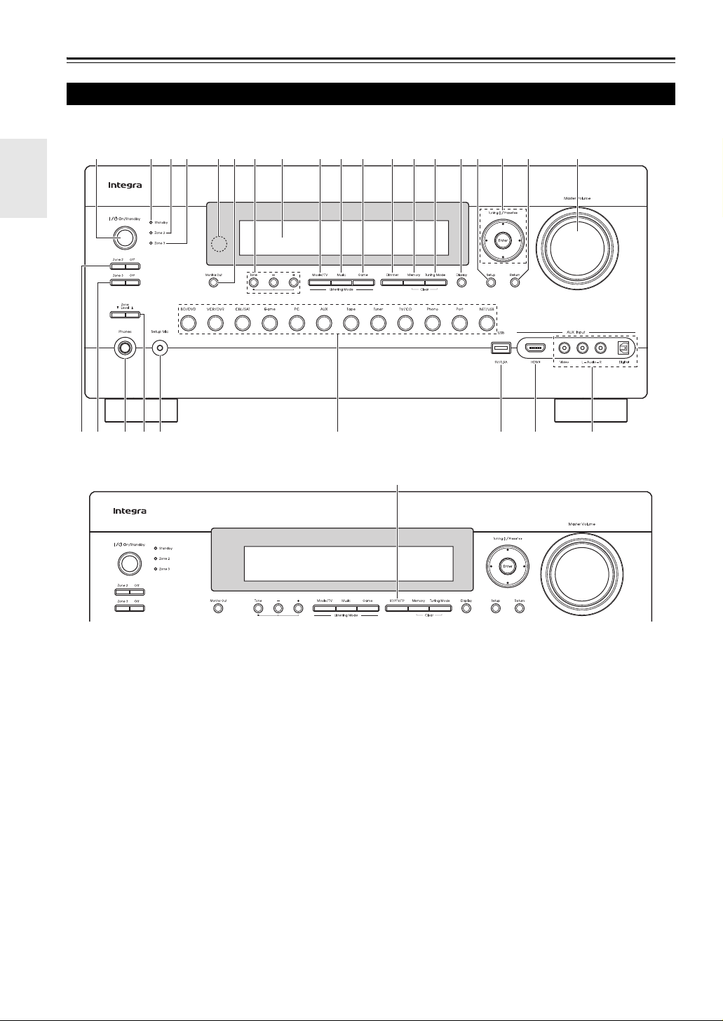
Front Panel
North American models
w
c
defhgijklmn op
b
yA
C
a
u x z
vt
Australian models
rsq
B
The actual front panel has various logos printed on it. They are not shown here for clarity.
The page numbers in parentheses show where you can find the main explanation for each item.
a On/Standby button (➔ 25)
b Standby indicator (➔ 25)
c Zone 2 indicator (➔ 83)
d Zone 3 indicator (➔ 83)
e Remote control sensor/transmitter (➔ 4)
f Monitor Out button (➔ 50)
g Ton e and –/+ buttons (➔ 68, 84)
h Display (➔ 9)
i Movie/TV button (➔ 42)
j Music button (➔ 42)
k Game button (➔ 42)
l Dimmer button (North American models) (➔ 26)
m Memory button (➔ 33)
En
n Tuning Mode button (➔ 32)
o Display button (➔ 26)
p Setup button (➔ 49)
q Tuning, Preset (➔ 32 to 33), arrow and Enter
buttons
r Return button
s Master Volume control (➔ 26)
t Zone 2 and Off buttons (➔ 83)
u Zone 3 and Off buttons (➔ 83)
v Phones jack (➔ 28)
w Zone Level buttons (➔ 84)
x Setup Mic jack (➔ 30)
8
y Input selector buttons (BD/DVD, VCR/DVR,
CBL/SAT, Game, PC, AUX, Ta pe, Tun er,
TV/CD, Phono, Port and NET/USB) (➔ 26)
z USB port (➔ 79, 87)
A AUX Input HDMI jack (➔ 19)
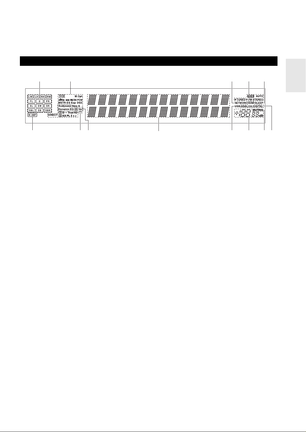
Display
B AUX Input jacks (Video, Audio L/R and Digital)
(➔ 20)
C RT/PTY/TP button (Australian models) (➔ 39)
bda e
fgh
For detailed information, see the pages in parentheses.
a Speaker/channel indicators
b Listening mode and format indicators (➔ 42, 69)
c NETWORK indicator (➔ 72, 73, 77)
d Tuning indicators
RDS indicator (Australian models) (➔ 39)
AUTO indicator (➔ 32)
TUNED indicator (➔ 32)
FM STEREO indicator (➔ 32)
e SLEEP indicator (➔ 27)
f Bi AMP indicator (➔ 54)
i
g Headphone indicator (➔ 28)
h Audyssey indicator (➔ 29, 56)
Dynamic EQ indicator (➔ 59)
- (Dolby) Vol indicator (➔ 58)
Dynamic Vol indicator (➔ 60)
i Message area
j USB indicator (➔ 79, 87)
k Volume level (➔ 26)
l MUTING indicator (➔ 27)
m Audio input indicators
c
jkl
m
En
9
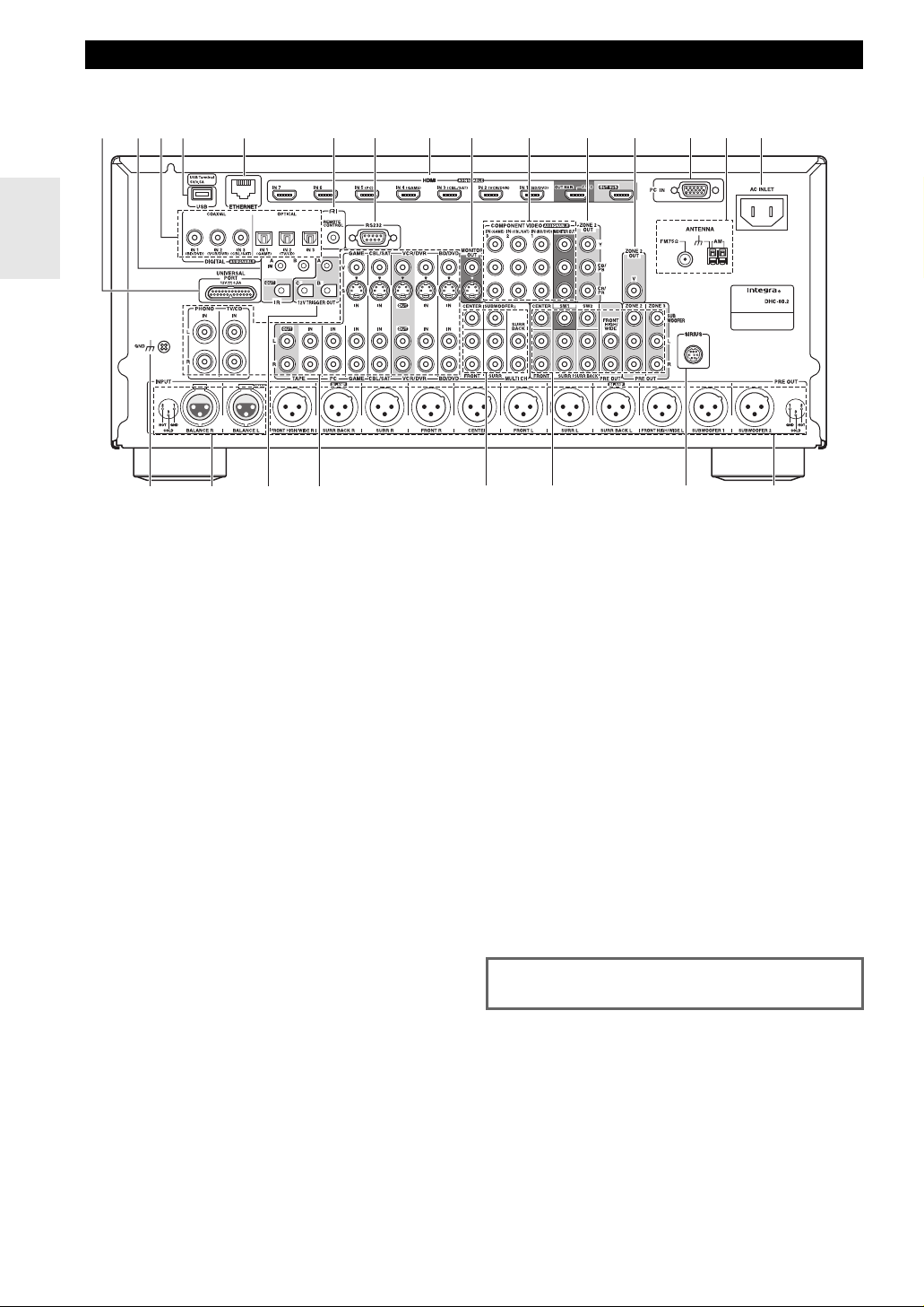
Rear Panel
North American models
g h ji lk nm
ad
bc
p
a UNIVERSAL PORT jack
b IR IN (A/B) and OUT jacks
c DIGITAL IN COAXIAL and OPTICAL jacks
d USB port
e ETHERNET port
f u REMOTE CONTROL jack
g RS232 terminal
Terminal for control.
h HDMI IN and HDMI output (HDMI OUT MAIN and
HDMI OUT SUB) jacks
i MONITOR OUT V and S jacks
j COMPONENT VIDEO IN and MONITOR OUT
jacks
k COMPONENT VIDEO ZONE 2 OUT jacks
l ZONE 2 OUT V jack
m PC IN port
n FM ANTENNA jack and AM ANTENNA terminal
o AC INLET
p GND screw
q INPUT jacks (BALANCE L/R)
e
qr
f
st
o
u
r 12V TRIGGER OUT (A/B/C) jacks
s Composite video, S-Video and analog audio jacks
(BD/DVD IN, VCR/DVR IN and OUT, CBL/SAT IN,
GAME IN, PC IN, TAPE IN and OUT, TV/CD IN
and PHONO IN)
t MULTI CH input jacks
(FRONT L/R, CENTER, SURR L/R,
SURR BACK L/R and SUBWOOFER)
u PRE OUT jacks
(FRONT L/R, CENTER, SURR L/R,
SURR BACK L/R, FRONT HIGH/WIDE L/R,
SW1, SW2, ZONE 2 L/R/SUBWOOFER and
ZONE 3 L/R/SUBWOOFER)
v SIRIUS antenna jack (North American models)
w PRE OUT jacks
(FRONT L/R, CENTER, SURR L/R,
SURR BACK L/R, FRONT HIGH/WIDE L/R,
SUBWOOFER 1 and SUBWOOFER 2)
See “Connecting the AV Controller” for connection
information (➔ 13 to 24).
vw
En
10
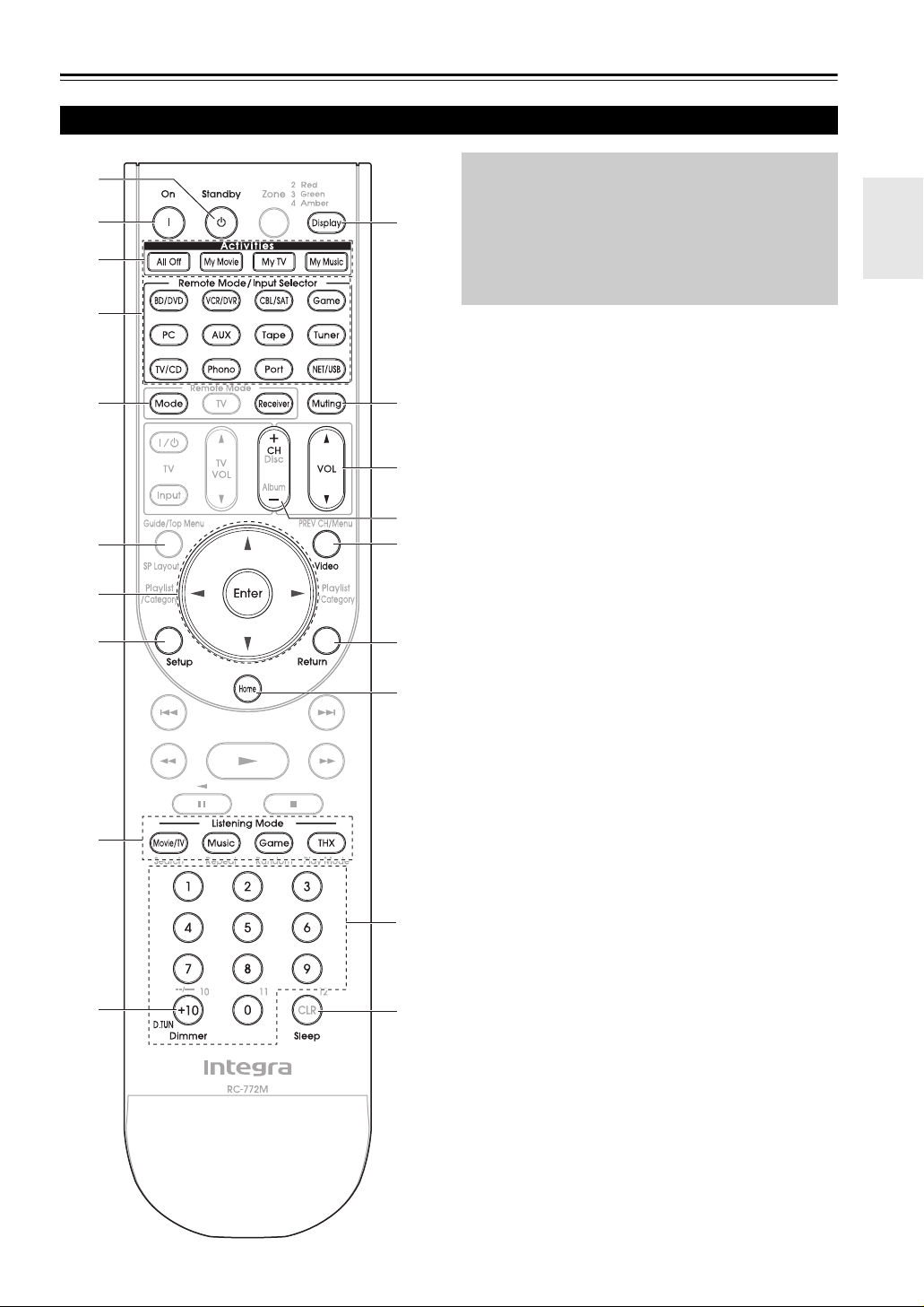
Remote Controller
Controlling the AV Controller
a
b
c
d
*1
*2
e
a
f
i
j
k
c
*4
l
m
To control the AV controller, press Receiver to select
Receiver mode.
You can also use the remote controller to control
Integra/Onkyo Blu-ray Disc/DVD player, CD player
and other components.
See “Entering Remote Control Codes” for more
details (➔ 94).
For detailed information, see the pages in parentheses.
a Standby button (➔ 25)
b On button (➔ 25)
c Activities buttons (All Off, My Movie, My TV and
*3
My Music) (➔ 28, 99)
d Remote Mode/Input Selector buttons (BD/DVD,
*3
*3
VCR/DVR, CBL/SAT, Game, PC, AUX, Tap e,
Tune r, TV/CD, Phono, Port and NET/USB)
(➔ 26)
e Arrow q/w/e/r and Enter buttons
f Setup button (➔ 49)
g Listening Mode buttons (Movie/TV, Music,
Game and THX) (➔ 42)
h Dimmer button (➔ 26)
i Display button (➔ 26)
j Muting button (➔ 27)
k VOL q/w button (➔ 26)
l Return button
m Home button (➔ 27)
n Sleep button (➔ 27)
g
h
b
d
n
■ Controlling the tuner
To control the AV controller’s tuner, press Tune r (or
Receiver).
You can select AM or FM by pressing Tu ne r repeatedly.
a Arrow q/w buttons (➔ 32, 35)
b D.TUN button (Tun er remote mode only) (➔ 32,
35)
c CH +/– button (➔ 33, 36)
d Number buttons (➔ 32, 35)
*1
When you want to change the remote controller mode without
changing the current input source, press Mode and within
about 8 seconds, press Remote Mode. Then, with the AV
controller’s remote controller, you can control the component
corresponding to the button you pressed.
*2
SP Layout is not used for this model.
*3
These buttons can be used when not in Receiver mode, and
when a Remote Mode other than Receiver mode is selected.
(Pressing Home switches to Receiver mode.)
*4
Video functions as a short cut of Video section of Home
menu (➔ 27).
En
11
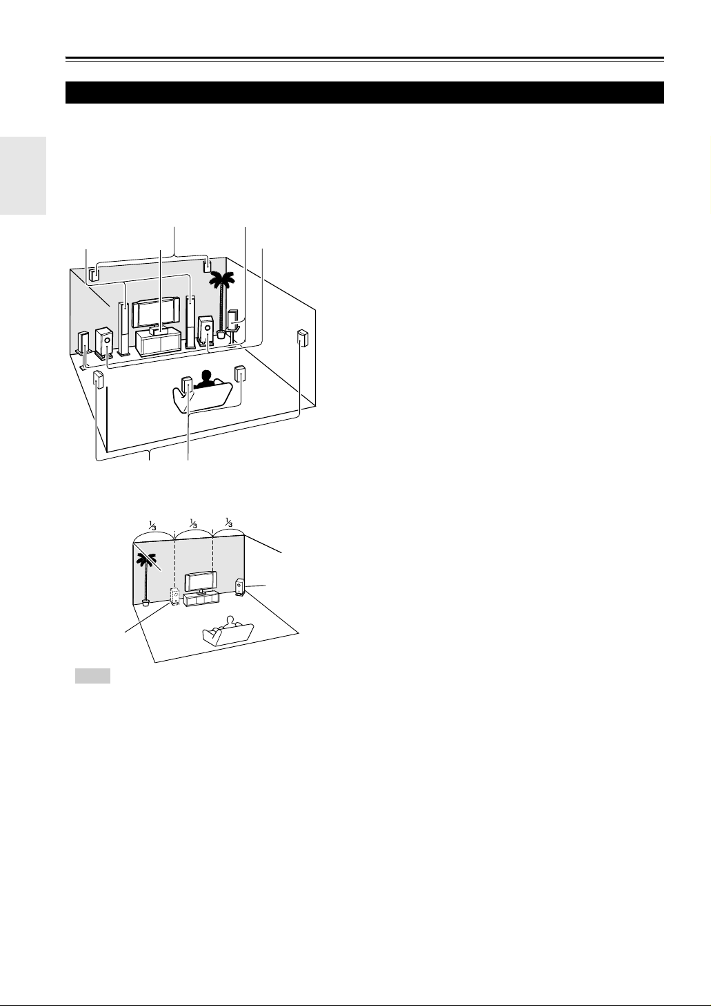
About Home Theater
Enjoying Home Theater
Thanks to the AV controller’s superb capabilities, you can enjoy surround sound with a real sense of movement in your
own home—just like being in a movie theater or concert hall. With Blu-ray Discs or DVDs, you can enjoy DTS and
Dolby Digital. With analog or digital TV, you can enjoy Dolby Pro Logic IIx, DTS Neo:6, or Onkyo’s original DSP listening modes.
You can also enjoy THX Surround EX (THX-certified THX speaker system recommended).
abFront speakers (Left and Right)
ij
de
cb
gh
a
1/3 of wall
position
Tip
• To find the best position for your subwoofer, while
playing a movie or some music with good bass,
experiment by placing your subwoofer at various
positions within the room, and choose the one that
provides the most satisfying results.
kl
f
Corner
position
These output the overall sound. Their role in a home theater is to provide a solid anchor for the sound image. They should be positioned
facing the listener at about ear level, and equidistant from the TV.
Angle them inward so as to create a triangle, with the listener at the
apex.
c Center speaker
This speaker enhances the front speakers, making sound movements
distinct and providing a full sound image. In movies it’s used mainly
for dialog. Position it close to your TV facing forward at about ear
level, or at the same height as the front speakers.
deSurround speakers (Left and Right)
These speakers are used for precise sound positioning and to add realistic ambience. Position them at the sides of the listener, or slightly
behind, about 2 to 3 feet (60 to 100 cm) above ear level. Ideally they
should be equidistant from the listener.
f Subwoofer(s)
The subwoofer handles the bass sounds of the LFE (Low-Frequency
Effects) channel. The volume and quality of the bass output from your
subwoofer will depend on its position, the shape of your listening
room, and your listening position. In general, a good bass sound can be
obtained by installing the subwoofer in a front corner, or at one-third
the width of the wall, as shown.
ghSurround back speakers (Left and Right)
These speakers are necessary to enjoy Dolby Digital EX, DTS-ES
Matrix, DTS-ES Discrete, THX Surround EX, etc. They enhance the
realism of surround sound and improve sound localization behind the
listener. Position them behind the listener about 2 to 3 feet (60 to
100 cm) above ear level.
ijFront high speakers (Left and Right)
These speakers are necessary to enjoy Dolby Pro Logic IIz Height, and
Audyssey DSX™. They significantly enhance the spatial experience.
Position them at least 3.3 feet (100 cm) above the front speakers (preferably as high as possible) and at an angle slightly wider than the front
speakers.
klFront wide speakers (Left and Right)
These speakers are necessary to enjoy Audyssey DSX. They significantly enhance the spatial experience. Position them well outside of the
front speakers. See also
about optimum speaker placement for Audyssey DSX.
http://www.audyssey.com/technology/dsx.html
En
12
Connections
Connecting the AV Controller
Connecting Your Speakers
The AV controller is designed to be used with a separate multichannel power amplifier. You connect the AV controller’s
PRE OUT jacks to the amplifier’s inputs, and connect your speakers to the amplifier’s speakers terminals. Speaker settings such as crossover frequency and distance are set on the AV controller.
Speaker Configuration
The following table indicates the channels you should use depending on the number of speakers that you have.
For 9.2-channel surround-sound playback, you need 9 speakers and 2 powered subwoofers.
Number of speakers 2 3 45677788999
Front speakers ✔✔✔✔✔✔✔✔✔✔✔✔✔
Center speaker ✔ ✔✔✔✔✔✔✔✔✔✔
Surround speakers ✔✔✔✔✔✔✔✔✔✔✔
Surround back speaker
*1
Surround back speakers ✔✔✔
Front high speakers
Front wide speakers
*1
If you’re using only one surround back speaker, connect it to the SURR BACK L output.
*2
If you use the front high and wide speakers at the same time, you need to set the “Front High + Front Wide” setting to “Ye s”
*2
(➔ 54).
No matter how many speakers you use, 2 powered subwoofers are recommended for a really powerful and solid bass.
To get the best from your surround sound system, you need to set the speaker settings. You can do this automatically
(➔ 29) or manually (➔ 54).
✔✔✔
✔✔✔✔
✔✔✔✔
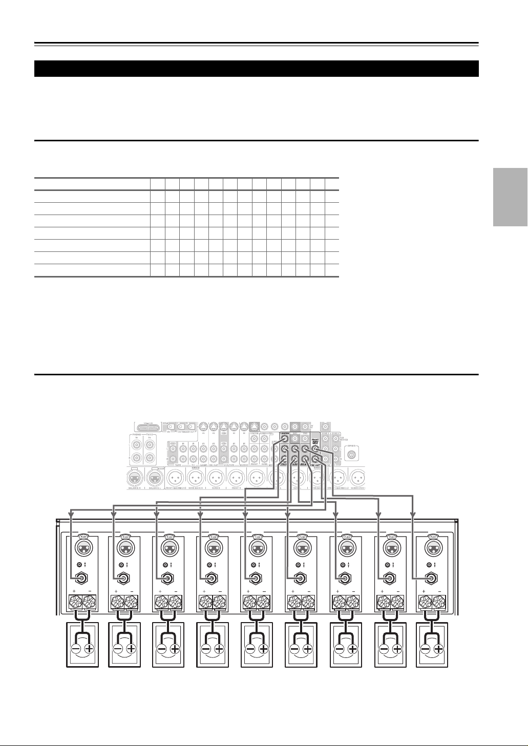
Connecting a Power Amplifier with RCA Inputs
You can connect the AV controller to a multichannel power amplifier with RCA input jacks by using a multichannel RCA
audio cable or several stereo RCA audio cables.
See your multichannel power amplifier’s instruction manual for more information on connecting speakers.
AV controller
Multichannel
power amplifier
FRONT HIGH/
FRONT WIDE
RIGHT
OUTPUT
INPUT
SELECT
SURROUND BACK
RIGHT
INPUT
SELECT
OUTPUT OUTPUT OUTPUT OUTPUT OUTPUT OUTPUT OUTPUT
SURROUND
RIGHT
INPUT
SELECT
FRONT
RIGHT
INPUT
SELECT
FUSE
INPUT
SELECT
SPEAKER IMPEDANCE
4 OHMS MIN. PER EACH
SPEAKER TERMINAL
AC INLET
FRONT
LEFT
INPUT
SELECT
12V TRIGGER
IN OUT
SURROUND
LEFTCENTER
INPUT
SELECT
SURROUND BACK
LEFT
INPUT
SELECT
MODEL NO. RDA-7.1
FRONT HIGH/
FRONT WIDE
LEFT
INPUT
SELECT
OUTPUT
SEVEN CHANNEL AMPLIFIER
Front high/
Front wide
right speaker
Surround
back/Front
*1
wide right
speaker
*2
Surround
right
speaker
Front right
speaker
Center
speaker
Front left
speaker
Surround
left
speaker
Surround
back/Front
wide left
*2
speaker
Front high/
Front wide
left speaker
*1
En
13
Note
*1
Specify crossover frequency for the channel that you want to output in “Speaker Configuration” (➔ 54).
*2
If you use the front high and wide speakers at the same time, you need to set the “Front High + Front Wide” setting to “Ye s”
(➔ 54).
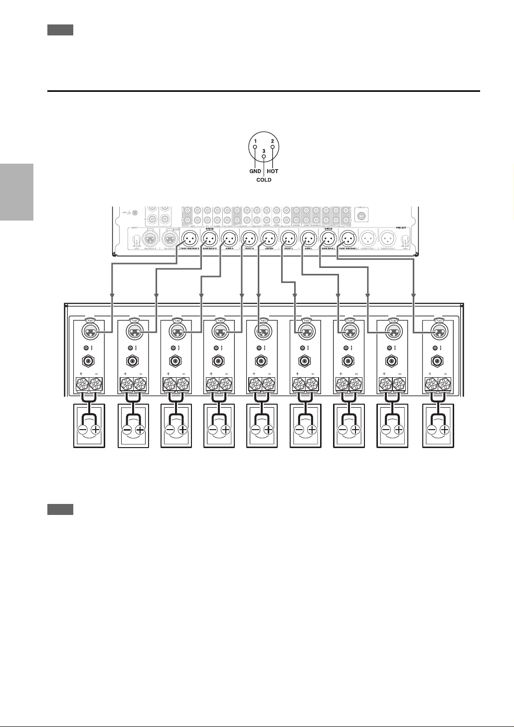
Connecting a Power Amplifier with XLR Inputs
You can connect the AV controller to a multichannel power amplifier with balanced XLR input jacks by using several
XLR audio cables.
The AV controller’s balanced PRE OUT jacks are wired as shown.
See your multichannel power amplifier’s instruction manual for more information on connecting speakers.
AV controller
Multichannel
power amplifier
FRONT HIGH/
FRONT WIDE
RIGHT
SURROUND BACK
RIGHT
SURROUND
RIGHT
FRONT
RIGHT
CENTER
FRONT
SURROUND
LEFT
LEFT
SURROUND BACK
LEFT
FRONT HIGH/
FRONTWIDE
LEFT
INPUT
SELECT
OUTPUT
Front high/
Front wide
right speaker
INPUT
SELECT
OUTPUT OUTPUT OUTPUT OUTPUT OUTPUT OUTPUT OUTPUT
Surround
back/Front
*1
wide right
*2
speaker
INPUT
SELECT
Surround
right
speaker
INPUT
SELECT
Front right
speaker
FUSE
Center
speaker
INPUT
SELECT
SPEAKER IMPEDANCE
4 OHMS MIN. PER EACH
SPEAKER TERMINAL
AC INLET
INPUT
SELECT
12V TRIGGER
IN OUT
Front left
speaker
INPUT
SELECT
Surround
left
speaker
INPUT
SELECT
MODEL NO.
RDA-7.1
Surround
back/Front
wide left
*2
speaker
OUTPUT
SEVEN CHANNEL AMPLIFIER
Front high/
Front wide
left speaker
Note
*1
Specify crossover frequency for the channel that you want to output in “Speaker Configuration” (➔ 54).
*2
If you use the front high and wide speakers at the same time, you need to set the “Front High + Front Wide” setting to “Ye s”
(➔ 54).
INPUT
SELECT
*1
En
14
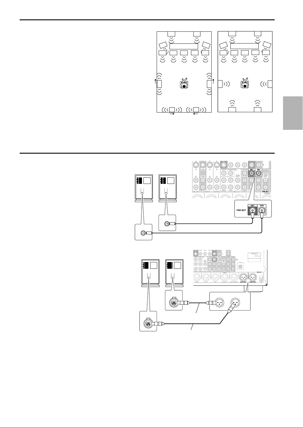
Using Dipole Speakers
You can use dipole speakers for the surround and surround
back speakers. Dipole speakers output the same sound in two
directions.
Dipole speakers typically have an arrow printed on them to
indicate how they should be positioned. The surround dipole
speakers should be positioned so that their arrows point
toward the TV/screen, while the surround back dipole speakers should be positioned so that their arrows point toward
each other, as shown.
ab Front speakers
c Center speaker
de Surround speakers
f Subwoofer(s)
gh Surround back speakers
ij Front high speakers
kl Front wide speakers
Connecting the Powered Subwoofers
Using a suitable cable, connect the AV controller’s
SW1 PRE OUT, SW2 PRE OUT to an input on
your powered subwoofer, as shown. If your subwoofer is unpowered and you’re using an external
amplifier, connect the SW1 PRE OUT, SW2
PRE OUT to an input on the amp.
You can connect the powered subwoofer with each
jacks respectively. Level and distance can be set
individually for each output. If you use one subwoofer, connect it to SW1 PRE OUT.
Powered subwoofer
LINE INPUT
LINE INPUT
Dipole speakers
ij
f
TV/screen
a
kk
de
LINE INPUT
cb
gh
LINE INPUT
f
lc
Normal speakers
ij
f
TV/screen
a
de
gh
f
l
b
You can also connect a powered subwoofer to the AV
controller’s balanced SUBWOOFER 1 PRE OUT,
SUBWOOFER 2 PRE OUT jack by using a balanced XLR cable.
You can connect the powered subwoofer with each
jacks respectively. Level and distance can be set individually for each output. If you use one subwoofer,
connect it to SUBWOOFER 1 PRE OUT.
Powered subwoofer
LINE INPUT LINE INPUT
INPUT
INPUT
Balanced XLR cable
Balanced XLR cable
SUBWOOFER 1
PRE OUT
SUBWOOFER 2
En
15
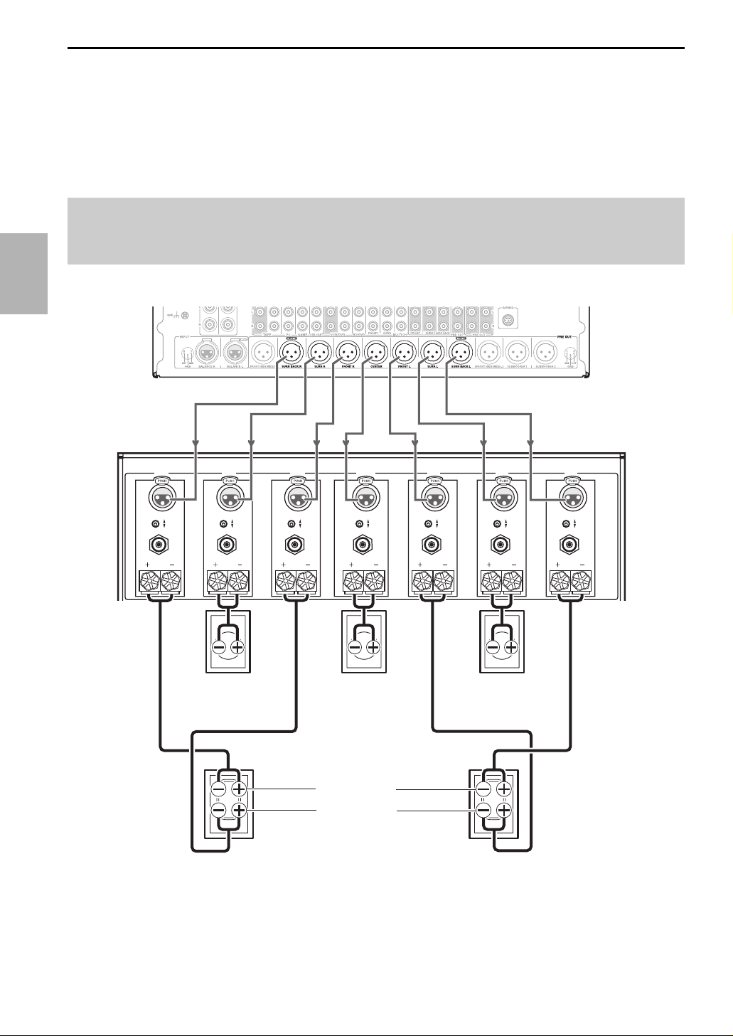
Bi-amping the Front Speakers
The FRONT L/R and SURR BACK L/R outputs can be used with front speakers and surround back speakers, respectively, or bi-amped to provide separate tweeter and woofer feeds for a pair of front speakers that support bi-amping, providing improved bass and treble performance.
• When bi-amping is used, the AV controller is able to feed up to 7.2 speakers in the main room.
• For bi-amping, the FRONT L/R outputs feed the front speakers’ woofer terminals. And the SURR BACK L/R
outputs feed the front speakers’ tweeter terminals.
• Once you’ve completed the bi-amping connections shown below and turned on the AV controller, you must set the
“Speakers Type(Front)” setting to “Bi-Amp” to enable bi-amping (➔ 54).
Important:
• When making the bi-amping connections, be sure to remove the jumper bars that link the speakers’ tweeter (high) and woofer (low)
terminals.
• Bi-amping can only be used with speakers that support bi-amping. Refer to your speaker manual.
See your multichannel power amplifier’s instruction manual for more information on connecting speakers.
AV controller
Multichannel
power amplifier
SURROUND BACK
RIGHT
INPUT
SELECT
OUTPUT OUTPUT OUTPUT OUTPUT OUTPUT OUTPUT OUTPUT
SURROUND
RIGHT
INPUT
SELECT
Surround right
FRONT
RIGHT
INPUT
SELECT
CENTER
INPUT
SELECT
SPEAKER IMPEDANCE
4 OHMS MIN. PER EACH
SPEAKER TERMINAL
AC INLET
FUSE
Center speaker
FRONT
LEFT
INPUT
SELECT
12V TRIGGER
IN OUT
speaker
SURROUND
LEFT
INPUT
SELECT
Surround left
speaker
SURROUND BACK
LEFT
SEVEN CHANNEL AMPLIFIER
MODEL NO. RDA-7.1
Tweeter (high)
Woofer (low)
Front right speaker
Front left speaker
INPUT
SELECT
En
16
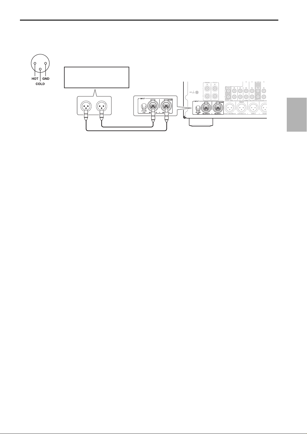
Connecting a Balanced Audio Source
You can connect a balanced audio source to the AV controller’s BALANCE L/R INPUT jacks by using two XLR audio
cables. To use the balanced input, you must assign it to an input selector (➔ 53). If you connect a mono source, use the
BALANCE L INPUT jack and set the “Input Channel” setting to “Mono(L)” (➔ 57). The AV controller’s balanced
INPUT jacks are wired as shown.
12
3
Stereo audio source with
balanced XLR output
En
17
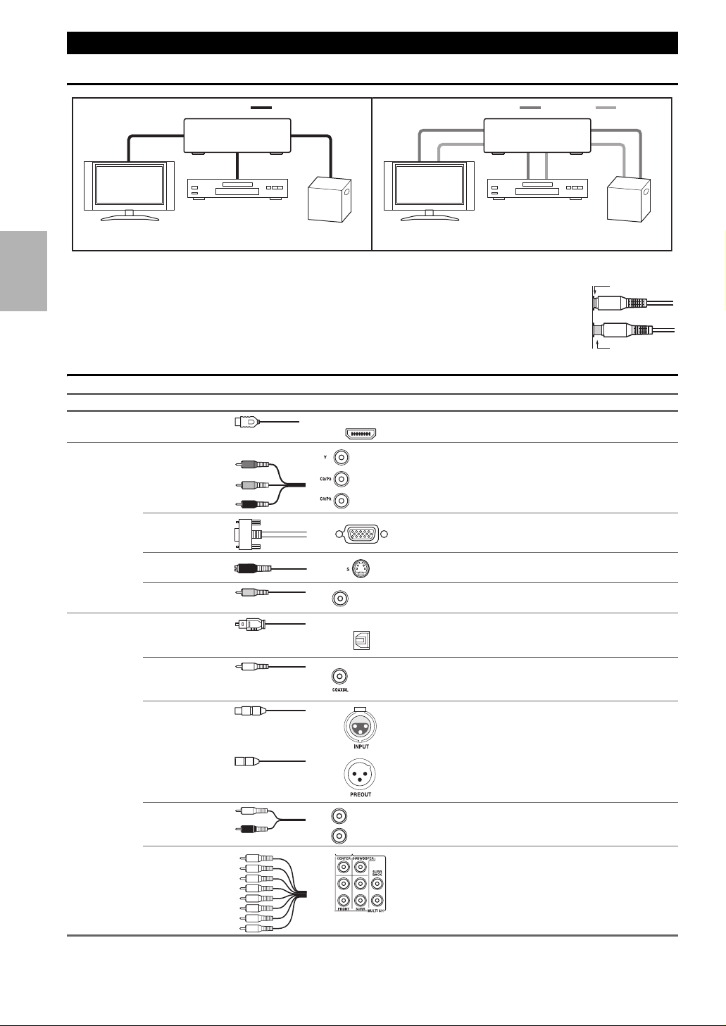
About AV Connections
Connected image with AV components
HDMI cable Other cables
: Video & Audio
AV controller
Blu-ray
TV, projector, etc.
Disc/DVD player
Game console
TV, projector, etc.
: Video
AV controller
Blu-ray
Disc/DVD player
: Audio
Game console
• Before making any AV connections, read the manuals supplied with your AV components.
• Don’t connect the power cord until you’ve completed and double-checked all AV connections.
Right!
• Push plugs in all the way to make good connections (loose connections can cause noise or malfunctions).
• To prevent interference, keep audio and video cables away from power cords and speaker cables.
Wrong!
AV Cables and Jacks
Signal Cable Jack Description
Video and
Audio
Video Component video Component video separates the luminance (Y) and color
HDMI HDMI connections can carry digital video and audio.
Y
B/CB
P
PR/CR
HDMI
Green
Blue
Red
difference signals (P
B/CB, PR/CR), providing the best pic-
ture quality (some TV manufacturers label their component video sockets slightly differently).
Analog RGB This is a conventional analog interface to connect a PC and
a display device (also called D-Sub or D-subminiature).
Audio Optical digital
*
Available sampling rate for PCM input signal is 32/44.1/48/88.2/96 kHz. Even 176.4/192 kHz is effective in case of the HDMI connection.
En
18
S-Video S-Video separates the luminance and color signals and pro-
vides better picture quality than composite video.
Composite video Composite video is commonly used on TVs, VCRs, and
audio
V
Yellow
OPTICAL
other video equipment.
Optical digital connections allow you to enjoy digital
*
sound such as PCM
, Dolby Digital or DTS. The audio
quality is the same as coaxial.
Coaxial digital
audio
Orange
Coaxial digital connections allow you to enjoy digital
*
sound such as PCM
, Dolby Digital or DTS. The audio
quality is the same as optical.
Balanced XLR This cable carries analog audio. Balanced XLR cables are
used for better noise immunity and longer cable runs.
Analog audio
(RCA)
Multichannel analog audio (RCA)
L
White
R
Red
Analog audio connections (RCA) carry analog audio.
This cable carries multichannel analog audio and is typically used to connect DVD players with a 7.1-channel analog audio output. Several standard analog audio cables can
be used instead of a multichannel cable.
Note
• The AV controller does not support SCART plugs.
• The AV controller’s optical digital jacks have shutter-type covers that open when an optical plug is inserted and close when it’s removed.
Push plugs in all the way.
Caution
• To prevent shutter damage, hold the optical plug straight when inserting and removing.
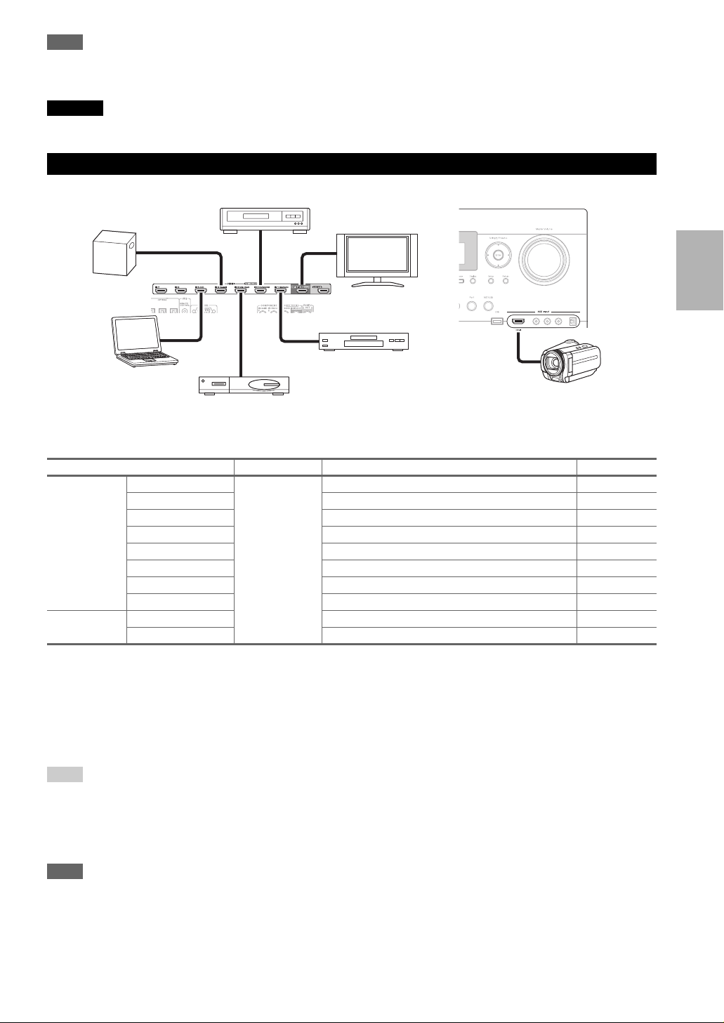
Connecting Your Components with HDMI
VCR or DVD recorder/Digital Video Recorder
Game console
TV, projector, etc.
Personal
computer
Satellite, cable, set-top box, etc.
Connect your components to the appropriate jacks. The default input assignments are shown below.
✔: Assignment can be changed (➔ 51 to 52).
Jack Signal Components Assignable
Input HDMI IN 1 Audio/Video Blu-ray Disc/DVD player ✔
HDMI IN 2 VCR or DVD recorder/Digital Video Recorder ✔
HDMI IN 3 Satellite, cable, set-top box, etc. ✔
HDMI IN 4 Game console ✔
HDMI IN 5 Personal computer ✔
HDMI IN 6 Other components ✔
HDMI IN 7 Other components ✔
AUX Input HDMI Camcorder
Output HDMI OUT MAIN TV
HDMI OUT SUB Projector, etc.
Blu-ray Disc/DVD player
Camcorder
Refer to “About HDMI” (➔ 106) and “Using an RIHD-compatible TV, Player, or Recorder” (➔ 107).
■ Audio return channel (ARC) function
Audio return channel (ARC) function enables an HDMI capable TV to send the audio stream to the HDMI OUT MAIN
of the AV controller. To use this function, you must select the TV/CD input selector.
• To use ARC function, you must select the TV/CD input selector, your TV must support ARC function and “HDMI
Control(RIHD)” is set to “On” (➔ 66).
Tip
• To listen to audio received by the HDMI IN jacks through your TV’s speakers:
– Set the “TV Control” setting to “On” (➔ 67) for an p-compatible TV.
– Set the “Audio TV Out” setting to “On” (➔ 66) when the TV is not compatible with p or the “TV Control” setting to “Off”.
– Set your Blu-ray Disc/DVD player’s HDMI audio output setting to PCM.
– To listen to TV audio through the AV controller, see “Connecting Your Components” (➔ 20).
Note
• When listening to an HDMI component through the AV controller, set the HDMI component so that its video can be seen on the TV
screen (on the TV, select the input of the HDMI component connected to the AV controller). If the TV power is off or the TV is set to
another input source, this may result in no sound from the AV controller or the sound may be cut off.
•When the “Audio TV Out” setting is set to “On” (➔ 66) to hear from your TV’s speakers, by controlling the AV controller’s volume,
the sound will be output from the AV controller’s speakers, too. When the
speakers of p-compatible TV, by controlling the AV controller’s volume, the AV controller’s speakers will produce sound while
the TV’s speakers are muted. To stop the AV controller’s speakers producing sound, change the settings, change your TV’s settings, or
turn down the AV controller’s volume.
“TV Control” setting is set to “On” (➔ 67) to hear from
En
19
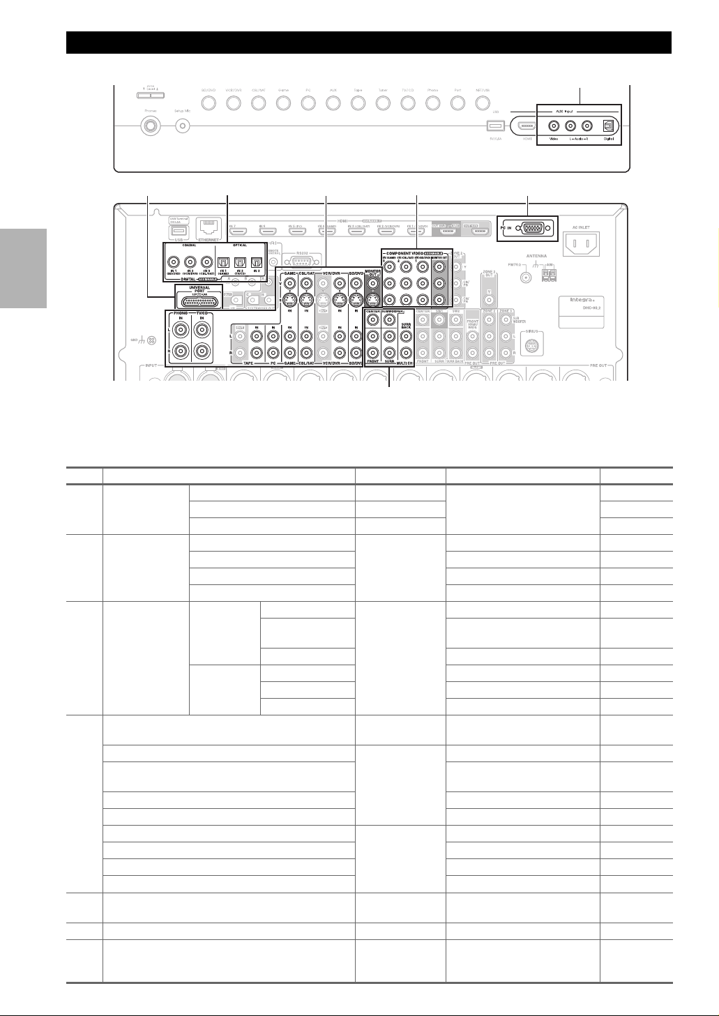
Connecting Your Components
Front
Rear
E
CB
D
F
A
G
Connect your components to the appropriate jacks. The default input assignments are shown below.
✔: Assignment can be changed (➔ 52, 53).
No. Jack Signal Components Assignable
AUX Input Video Composite video Camcorder, etc
A
Audio L/R Analog audio
Digital Digital audio
En
COMPONENT
B
VIDEO
DIGITAL COAXIAL IN 1 (BD/DVD) Digital audio Blu-ray Disc/DVD player ✔
C
MONITOR OUT Composite video
D
BD/DVD IN Analog audio,
VCR/DVR IN VCR or DVD recorder/digital
CBL/SAT IN Satellite, cable, set-top box, etc.
GAME IN Game console
PC IN Analog audio Personal computer
TAPE IN Cassette tape deck, MD, CD-R
TV/CD IN
PHONO IN
UNIVERSAL PORT Analog
E
*2
PC IN
F
Multichannel input
G
IN 1 (BD/DVD) Component video Blu-ray Disc/DVD player ✔
IN 2 (CBL/SAT) Satellite, cable, set-top box, etc. ✔
IN 3 (GAME) Game console ✔
MONITOR OUT TV, projector, etc.
IN 2 (VCR/DVR) VCR or DVD recorder/digital
IN 3 (CBL/SAT) Satellite, cable, set-top box, etc. ✔
OPTICAL IN 1 (GAME) Game console ✔
IN 2 (TV/CD) TV, CD player ✔
IN 3
and S-Video
composite video
and S-Video
audio/video
Analog RGB Personal computer
*3
Analog audio DVD player, DVD-Audio or
video recorder
Other components ✔
TV, projector, etc.
Blu-ray Disc/DVD player
video recorder
TV, CD player, Turntable
Turntable
Universal port optional dock
(UP-A1 etc.)
Super Audio CD-capable player,
or an MPEG decorder
*1
*1
20
✔
✔
Note
*1
Connect a turntable (MM) that has built-in a phono preamp to TV/CD IN or connect it to PHONO IN with the phono preamp turned
off. If your turntable (MM) doesn’t have a phono preamp, connect to PHONO IN. If your turntable has a moving coil (MC) type cartridge, you’ll need a commercially available MC head amp or MC transformer to connect to PHONO IN. See your turntable’s manual for details.
If your turntable has a ground wire, connect it to the AV controller’s GND screw. With some turntables, connecting the ground wire
may produce an audible hum. If this happens, disconnect it.
*2
When you connect your personal computer to PC IN and select PC input selector, video of the personal computer is output from
HDMI output. However, because the AV controller selects the video input in the order of HDMI > component > analog RGB, if you
have assigned HDMI IN to the PC input selector, the AV controller will output signals from HDMI IN in priority to PC IN.
*3
Before using the multichannel input, you must assign it to an input selector. See “Analog Audio Input” (➔ 53). To select the multichannel input, see “Audio Selector” (➔ 70). To adjust the subwoofer sensitivity for the multichannel input, see “Subwoofer Input
Sensitivity” (➔ 53).
• The AV controller can output audio and video signals from the AUX Input jacks to the VCR/DVR OUT jacks.
• With connection D, you can listen and record audio from the external components while you are in Zone 2 or 3. You can listen and
record audio from the external components in the main room; you can listen to the audio in Zone 2 or 3 as well.
• With connection C, you can enjoy Dolby Digital and DTS. (To record or listen in Zone 2 or 3 as well, use C and D.)
■ How to record the video
With the connections described above, you cannot record the video through the AV controller. To make a connection for
video recording (➔ 41).
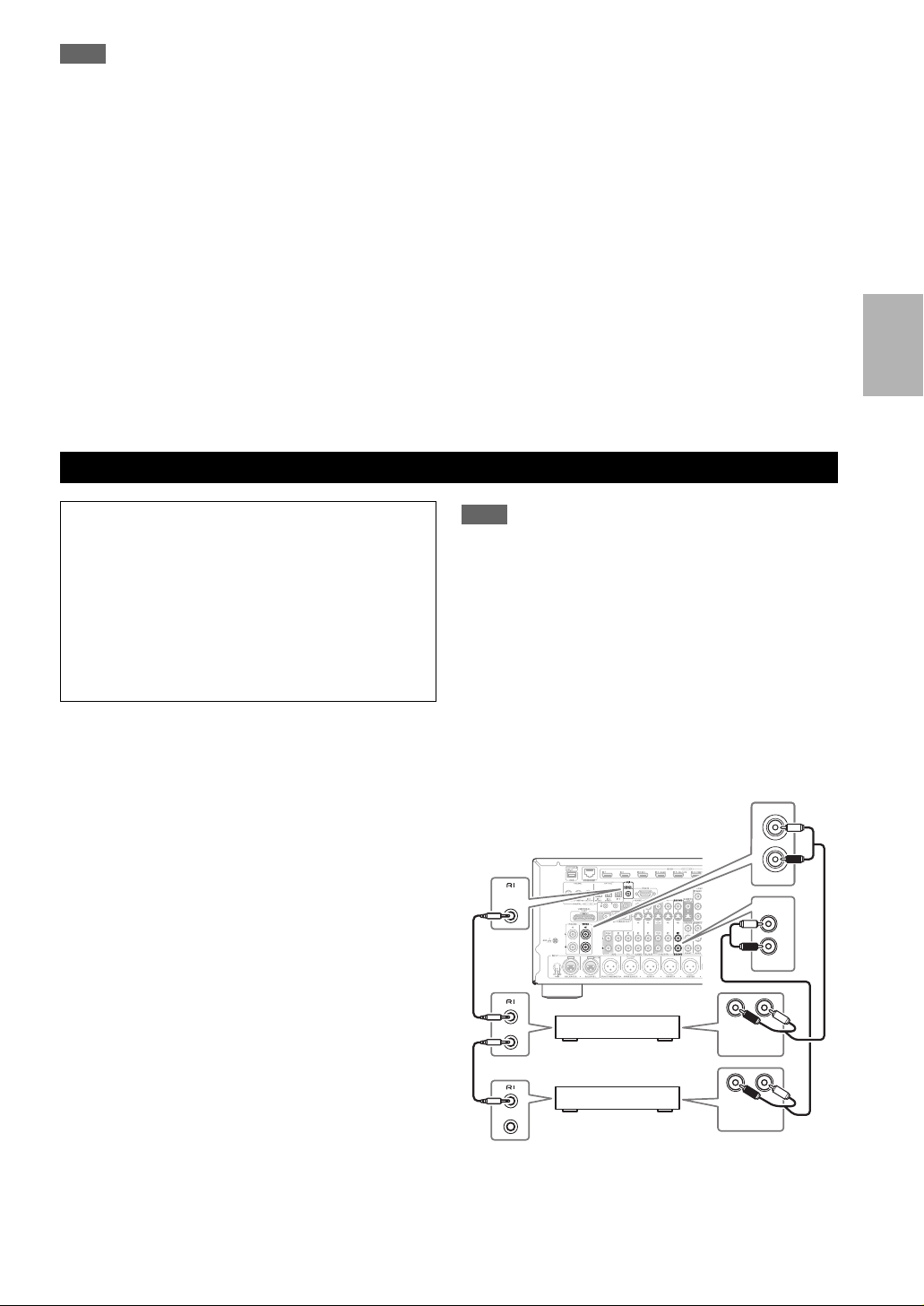
Connecting Integra/Onkyo u Components
Step 1:
Make sure that each Integra/Onkyo component is connected with an analog audio cable (connection D in the
hookup examples) (➔ 20).
Step 2:
Make the u connection (see illustration below).
Step 3:
If you’re using an RI Dock, or cassette tape deck,
change the Input Display (➔ 28).
With u (Remote Interactive), you can use the following
special functions:
■ Auto Power On
When you start playback on a component connected via
u while the AV controller is on Standby, the AV con-
troller will automatically turn on and select that component as the input source.
■ Direct Change
When playback is started on a component connected via
u, the AV controller automatically selects that compo-
nent as the input source.
■ Remote Control
You can use the AV controller’s remote controller to
control your other u-capable Integra/Onkyo compo-
nents, pointing the remote controller at the AV controller’s remote control sensor instead of the component.
You must enter the appropriate remote control code first
(➔ 94).
Note
•Use only u cables for u connections. u cables are supplied
with Integra/Onkyo players (DVD, CD, etc.).
• Some components have two u jacks. You can connect either
one to the AV controller. The other jack is for connecting addi-
tional u-capable components.
• Connect only Integra/Onkyo components to u jacks. Connecting other manufacturer’s components may cause a malfunction.
• Some components may not support all u functions. Refer to
the manuals supplied with your other Integra/Onkyo components.
• While Zone 2 and Zone 3 is on, the Auto Power On and Direct
Change u functions do not work.
• Do not use u connections if you use HDMI Control(RIHD)
(➔ 66).
IN
L
R
ANALOG
AUDIO OUT
ANALOG
AUDIO OUT
TV/CD
IN
L
R
BD/DVD
LR
LR
REMOTE
CONTROL
e.g., CD player
e.g., DVD player
En
21
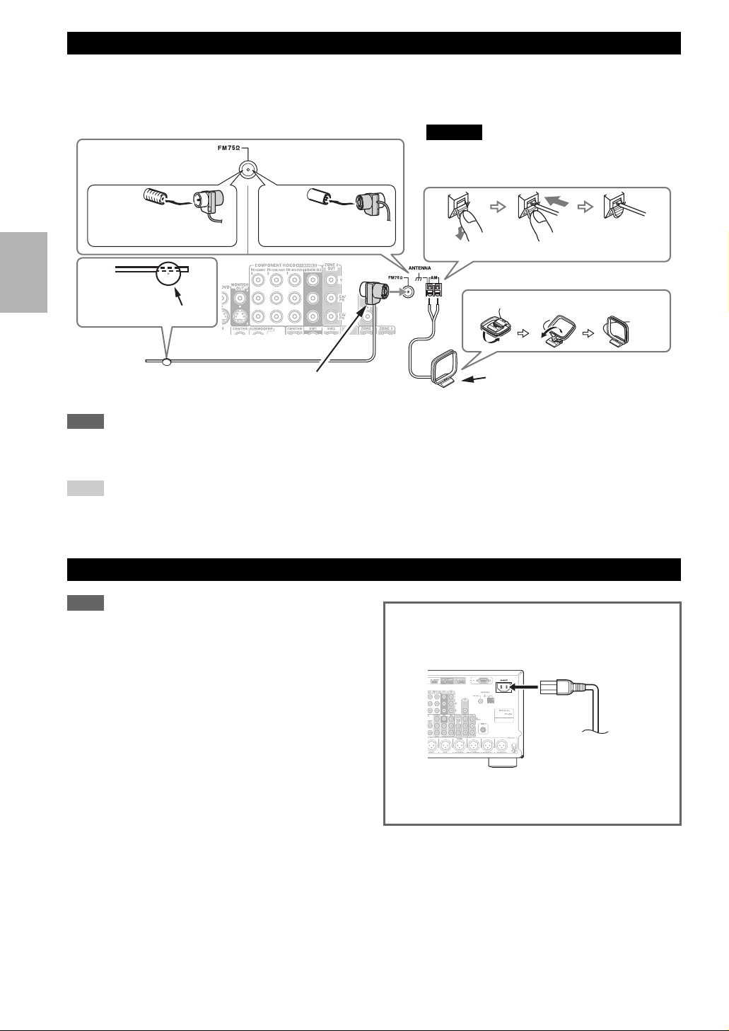
Connecting Antenna
This section explains how to connect the supplied indoor FM antenna and AM loop antenna.
The AV controller won’t pick up any radio signals without any antenna connected, so you must connect the antenna to
use the tuner.
Caution
(North American
models)
(Australian models)
• Be careful that you don’t injure yourself when
using thumbtacks.
Insert the plug fully
into the jack.
Thumbtacks, etc.
Note
• Once your AV controller is ready for use, you’ll need to tune into a radio station and position the antenna to achieve the best possible
reception.
• Keep the AM loop antenna as far away as possible from your AV controller, TV, speaker cables, and power cords.
Tip
• If you cannot achieve good reception with the supplied indoor FM antenna, try a commercially available outdoor FM antenna instead.
• If you cannot achieve good reception with the supplied indoor AM loop antenna, try using it with a commercially available outdoor AM
antenna.
Insert the plug fully
into the jack.
Indoor FM antenna (supplied)
Push.
Assembling the AM loop antenna.
Insert wire. Release.
AM loop antenna (supplied)
Connecting the Power Cord
Note
• Before connecting the power cord, connect all of your speakers and AV components.
• Turning on the AV controller may cause a momentary power
surge that might interfere with other electrical equipment on the
same circuit. If this is a problem, plug the AV controller into a
different branch circuit.
• Do not use a power cord other than the one supplied with the AV
controller. The supplied power cord is designed exclusively for
use with the AV controller and should not be used with any other
equipment.
• Never disconnect the power cord from the AV controller while
the other end is still plugged into a wall outlet. Doing so may
cause an electric shock. Always disconnect the power cord from
the wall outlet first, and then the AV controller.
Step 1:
Connect the supplied power cord to the AV controller’s
AC INLET.
To AC wall outlet
Step 2:
Plug the power cord into an AC wall outlet.
En
22
Which Connections Should I Use?
The AV controller supports several connection formats for compatibility with a wide range of AV equipment. The format
you choose will depend on the formats supported by your components. Use the following sections as a guide.
Video Connection Formats
Video component can be connected by using any one of the following video connection formats: composite video,
S-Video, PC IN (Analog RGB), component video or HDMI, the latter offering the best picture quality.
The AV controller can upconvert and downconvert between video formats, depending on the “Monitor Out” setting
(➔ 50), which generally determines whether video signals are upconverted for the component video output or the HDMI
output.
For optimal video performance, THX recommends that video signals pass through the system without upconversion (e.g., component video input through to component video output).
To by-pass video upconversion in the AV controller, simultaneously press the VCR/DVR and Return on the AV
controller. While continuing to hold down the VCR/DVR, press Return to toggle until “Skip” appears on the display. Release both buttons.
To use the video upconversion in the AV controller, repeat the above process until “Use” appears on the display and
release the buttons.
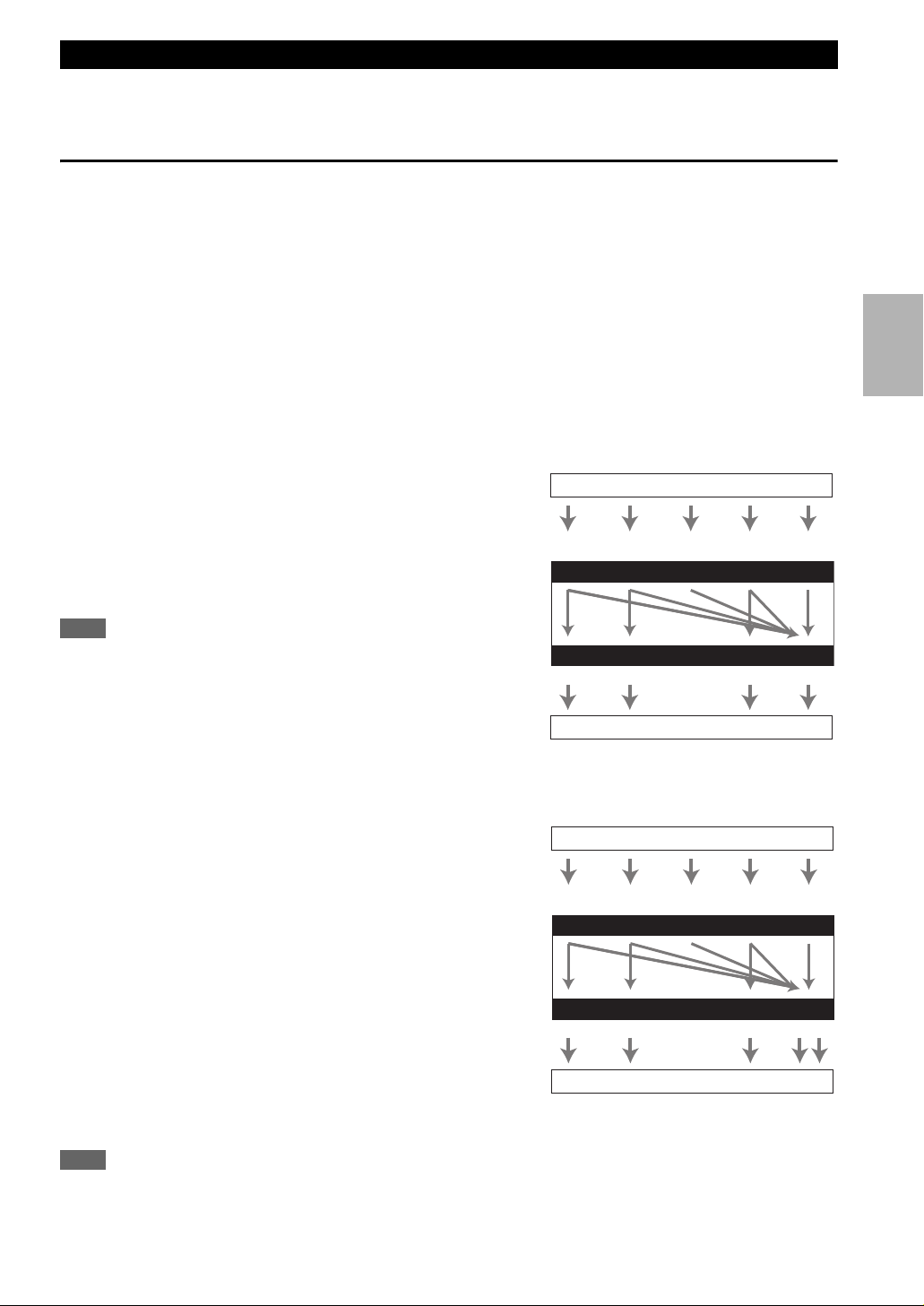
■ “Monitor Out” setting set to “HDMI Main” or “HDMI Sub”
Video input signals flow through the AV controller as
shown, with composite video, S-Video, PC IN (Analog
RGB) and component video sources all being upconverted
for the HDMI output. Use these settings if you connect the
AV c on t r ol l e r’ s HDMI OUT MAIN or HDMI OUT SUB,
Composite
respectively, to your TV.
The composite video, S-Video and component video outputs
pass through their respective input signals as they are.
Note
• If not connected to the same output you have selected in the “Monitor Out” setting, the “Monitor Out” setting will be automatically
switched to “Analog” (➔ 24).
In this case, the setting of the output resolution will be that for
HDMI output (➔ 50). Moreover, it will be switched to “1080i”
when “1080p” or “1080p/24” is selected, and to “Through” when
“Auto” is selected.
AV controller
Composite
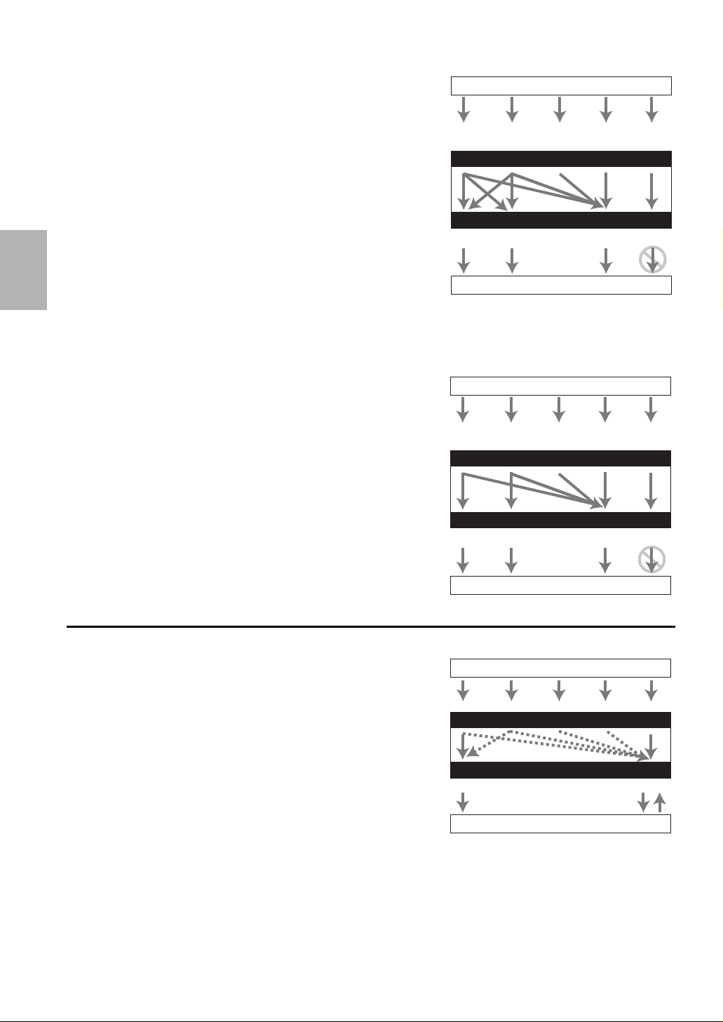
■ “Monitor Out” setting set to “Both”, “Both(Main)” or “Both(Sub)”
Video input signals flow through the AV controller as
shown, with composite video, S-Video, PC IN (Analog
RGB) and component video sources all being upconverted
for both HDMI outputs. Use these settings if you connect
the AV controller’s HDMI OUT MAIN and HDMI OUT
Composite
SUB to your TVs.
The composite video, S-Video and component video outputs
pass through their respective input signals as they are.
` Both: Video signals are output from both HDMI outputs
AV controller
at the resolution supported by both TVs. You cannot
select “Resolution” setting.
` Both(Main): Video signals are output from both HDMI
Composite
outputs but HDMI OUT MAIN will become a priority;
depending on the resolution, video signals may not be
output from HDMI OUT SUB.
` Both(Sub): Video signals are output from both HDMI outputs but HDMI OUT SUB will become a priority; depend-
ing on the resolution, video signals may not be output from HDMI OUT MAIN.
Note
•The “Monitor Out” setting will be automatically switched to “Analog” (➔ 50) if not connected to both outputs when “Both” is
selected or if not connected to a priority output when “Both(Main)” or “Both(Sub)” is selected.
Video Signal Flow Chart
Blu-ray Disc/DVD player, etc.
S-Video Component HDMI
S-Video Component HDMI
Video Signal Flow Chart
Blu-ray Disc/DVD player, etc.
S-Video Component
S-Video
PC IN
(Analog RGB)
IN
MONITOR OUT
TV, projector, etc.
PC IN
(Analog RGB)
IN
MONITOR OUT
TV, projector, etc
Component
HDMI
HDMI
En
23
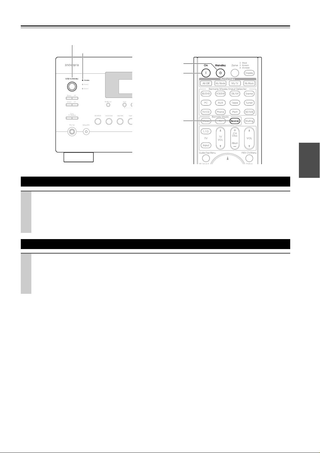
■ “Monitor Out” setting set to “Analog”
Video input signals flow through the AV controller as
shown, with composite video, S-Video and PC IN (Analog
RGB) sources being upconverted for the component video
output. Use this setting if you connect the AV control-
ler’s COMPONENT VIDEO MONITOR OUT to your
TV.
Composite video is upconverted to S-Video and S-Video is
downconverted to composite video. Note that these conversions only apply to the MONITOR OUT V and S outputs,
not the VCR/DVR OUT V and S outputs.
The composite video, S-Video and component video outputs pass through their respective input signals as they are.
This signal flow also applies when the “Resolution” setting is set to “Through” (➔ 51).
Video Signal Flow and the Resolution Setting
When the “Monitor Out” setting is set to “Analog”
(➔ 50), if the “Resolution” setting is set to anything other
than “Through” (➔ 51), the video signal flow will be as
shown here, with composite video, PC IN (Analog RGB)
and S-Video sources being upconverted for the component
video output.
The composite video, S-Video and component video outputs pass through their respective analog input signals as
they are. HDMI input signals are not output.
AV controller
AV controller
Video Signal Flow Chart
Blu-ray Disc/DVD player, etc.
Composite
S-Video Component
PC IN
(Analog RGB)
IN
MONITOR OUT
Composite
S-Video
Component
TV, projector, etc.
*1
For details, refer to “Video Resolution
Chart” (➔ 113).
Video Signal Flow Chart
Blu-ray Disc/DVD player, etc.
Composite
S-Video Component
PC IN
(Analog RGB)
IN
MONITOR OUT
Composite
S-Video
Component
HDMI
HDMI
1
*
HDMI
HDMI
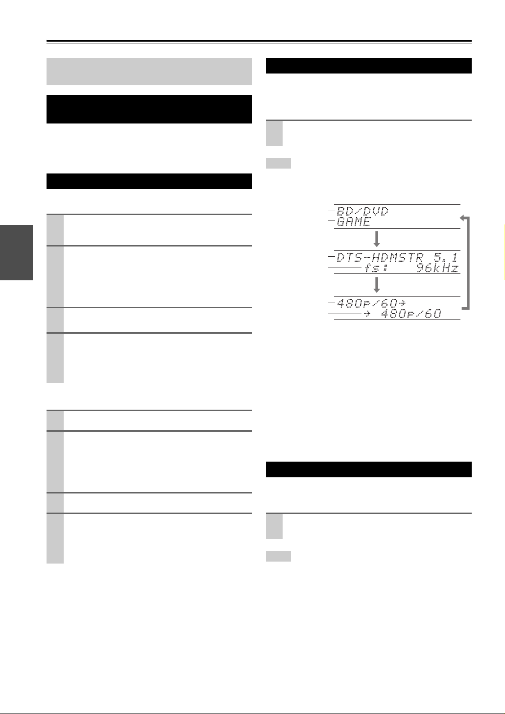
Audio Connection Formats
Audio component can be connected by using any of the
following audio connection formats: analog, analog multichannel, optical, coaxial, or HDMI.
When choosing a connection format, bear in mind that the
AV controller does not convert digital input signals for
analog line outputs and vice versa. For example, audio signals connected to an optical or coaxial digital input are not
output by the analog VCR/DVR OUT.
If signals are present at more than one input, the inputs
will be selected automatically in the following order of priority: HDMI, digital, analog.
En
24
TV, projector, etc.
Audio Signal Flow Chart
Blu-ray Disc/DVD player, etc.
AV controller
Multichannel
1
*
3
*
*1*
Optical
IN
3
1
*
OUT
TV, projector, etc.
*1
Depends on the “Audio TV Out” setting (➔ 66).
*2
This setting is available when “Audio Return Channel”
setting is set to “Aut o” (➔ 66). You must select the TV/CD
input selector and your TV must support ARC function.
*3
Only the front L/R channels are output.
HDMICoaxial Analog
1
*
HDMI Analog
2
*1*
Turning On & Basic Operations
Turning On/Off the AV Controller
On/Standby
Standby indicator
Standby
On
Receiver
Turn ing O n
Press On/Standby on the front panel.
or
Press Receiver followed by On on the remote controller.
The AV controller comes on, the display lights, and the Standby indicator goes off.
Pressing the remote controller’s On again will turn on any components connected via u.
Turn ing O ff
Press On/Standby on the front panel.
or
Press Receiver followed by Standby on the remote controller.
The AV controller will enter Standby mode. To prevent any loud surprises when you turn on the AV controller,
always turn down the volume before you turn it off.
En
25
Basic Operations
This manual describes the procedure using the
remote controller unless otherwise specified.
Selecting the Language Used for the Onscreen Setup Menus
You can determine the language used for the onscreen
setup menus. See “Language” in the “OSD Setup”
(➔ 65).
Playing the Connected Component
■ Operating on the AV controller
Use the input selector buttons to select the input
1
source.
Start playback on the source component.
2
See also:
• “Controlling Other Components” (➔ 92)
• “Controlling iPod” (➔ 87)
• “Listening to the Radio” (➔ 32)
To adjust the volume, use the Master Volume
3
control.
Select a listening mode and enjoy!
4
See also:
• “Using the Listening Modes” (➔ 42)
• “Audyssey” (➔ 59)
■ Operating with the remote controller
Press Receiver followed by Input Selector.
1
Start playback on the source component.
2
See also:
• “Controlling Other Components” (➔ 92)
• “Controlling iPod” (➔ 87)
• “Listening to the Radio” (➔ 32)
To adjust the volume, use VOL q/w.
3
Select a listening mode and enjoy!
4
See also:
• “Using the Listening Modes” (➔ 42)
• “Audyssey” (➔ 59)
Displaying Source Information
You can display various information about the current
input source as follows. (Components connected to the
UNIVERSAL PORT jack are excluded.)
Press Receiver followed by Display repeatedly to
cycle through the available information.
Tip
• Alternatively, you can use the AV controller’s Display.
The following information can typically be displayed.
Input source
Listening
*1
mode
Signal format
Input signal
*1
The input source is displayed with the default name even
when you have entered a custom name in “Name Edit”
(➔ 61).
*2
If the input signal is analog, no format information is displayed. If the input signal is PCM, the sampling frequency is
displayed. If the input signal is digital but not PCM, the signal
format and the number of channels is displayed. For some digital input signals, including multichannel PCM, the signal format, number of channels, and sampling frequency is
displayed.
Information is displayed for about three seconds, then the previously displayed information reappears.
*2
Sampling
frequency
resolution
Output
resolution
Setting the Display Brightness
You can adjust the brightness of the AV controller’s display.
Press Receiver followed by Dimmer repeatedly
to select: dim, dimmer, or normal brightness.
Tip
• (North American models) Alternatively, you can use the AV
controller’s Dimmer.
En
26

Muting the AV Controller
You can temporarily mute the output of the AV controller.
Press Receiver followed by Muting.
The output is muted and the MUTING indicator
flashes on the display.
Tip
• To unmute, press Muting again or adjust the volume.
• The Mute function is cancelled when the AV controller is set to
Standby.
Using the Sleep Timer
With the sleep timer, you can set the AV controller to turn
off automatically after a specified period.
Press Receiver followed by Sleep repeatedly to
select the required sleep time.
The sleep time can be set from 90 to 10 minutes in
10 minute steps.
The SLEEP indicator lights on the display when the
sleep timer has been set. The specified sleep time
appears on the display for about 5 seconds, then the
previous display reappears.
Tip
• If you need to cancel the sleep timer, press Sleep repeatedly
until the SLEEP indicator goes off.
• To check the time remaining until the AV controller sleeps, press
Sleep. Note that if you press Sleep while the sleep time is
being displayed, you’ll shorten the sleep time by 10 minutes.
Using the Home Menu
The Home menu provides you quick access to frequently
used menus without having to go through the long standard menu. This menu enables you to change settings and
view the current information.
Press Receiver followed by Home.
1
The following information will be superimposed on
the TV screen.
(The language is English only.)
BD/DVD
Audio
Video
Info
Input
Listening Mode
Use q/w/e/r to make the desired selection.
2
■ Audio
` Performs audio settings. For details, refer to
“Using the Audio Settings” (➔ 68).
■ Video
*1
` You can change the following settings: “Wide
Mode”, “Picture Mode”, “Brightness”, “Contrast”, “Hue” and “Saturation”.
The remote controller’s Video acts as a shortcut
for this menu.
See also:
• “Picture Adjust” (➔ 62)
*2*3
■ Info
` You can view the information of the following
items: “Audio”, “Video” and “Tu ne r”.
■ Input
*3*4
` You can select the input source while viewing
the information as follows: the name of input
selectors, input assignments, and radio information, and ARC function setting.
Press Enter to display the current input source,
followed by q/w to select the desired input
source. Pressing Enter again switches to the
selected input source.
■ Listening Mode
` You can select the listening modes that are
grouped in the following categories:
“Movie/TV”, “Music”, “Game” and “THX”.
Use q/w to select the category and e/r to
select the listening mode. Press Enter to
switch to the selected listening mode.
Note
*1
Only when you have selected “Custom” in the “Picture
Mode” (➔ 62), pressing Enter allows you to adjust the fol-
lowing items via the Home menu; “Brightness”, “Contrast”,
“Hue” and “Saturation”. Press Return to return to the picture mode setting.
*2
Depending on the input source and listening mode, not all
channels shown here output the sound.
*3
When you have entered a custom name in “Name Edit”
(➔ 61), the input source is displayed with that name. But
even if not, the component name may be displayed if the AV
controller receives it via HDMI connection (➔ 19).
*4
For the Port input selector, the name of Universal Port Option
Dock will be displayed.
En
27
Changing the Input Display
Using Activities to Start Easy Macros
When you connect an u-capable Onkyo component, you
must configure the input display so that u can work
properly.
This setting can be done only from the front panel.
Press Tape, Game or VCR/DVR so that “TAPE”,
1
“GAME” or “VCR/DVR” appears on the display.
Press and hold down Tap e, Game or VCR/DVR
2
(about 3 seconds) to change the input display.
Repeat this step to select “MD”, “CDR” or
“DOCK”.
For the Tap e input selector, the input display
changes in this order:
TAP E → MD → CDR
→
DOCK
→
For the Game input selector, the setting changes in
this order:
GAME ↔ DOCK
For the VCR/DVR input selector, the setting
changes in this order:
VCR/DVR ↔ DOCK
Note
• DOCK can be selected for the Ta pe, Game or VCR/DVR input
selector, but not at the same time.
• Enter the appropriate remote control code before using the
remote controller for the first time (➔ 92).
Using Headphones
Connect a pair of stereo headphones with a standard plug (1/4 inch or 6.3 mm) to the Phones
jack.
Note
• Always turn down the volume before connecting your headphones.
• While the headphones plug is inserted in the Phones jack, the
Headphone indicator, speaker/channel indicator FL and FR
lights.
• When you connect a pair of headphones, the listening mode is
set to Stereo, unless it’s already set to Stereo, Mono or Direct.
• Only the Stereo, Direct and Mono listening modes can be used
with headphones.
You can use Activities to execute a number of remote
control operations with a single button.
This button has the following two modes.
` Easy Macro mode:
You can turn on and off the AV controller, playback
components and TV.
` Normal Macro mode:
You can assign desired operations (➔ 97, 99).
Note
• If you set any one of the Activities to Normal Macro mode, all
the Activities will be set to Normal Macro mode.
• To use Activities, first assign the remote control codes of the
AV components you are using (➔ 94).
Starting Components Using Activities
Press My Movie, My TV, or My Music.
At purchase, Activities are set to Easy Macro mode
as the default setting.
The default actions are described below.
My Movie:
1. The TV turns on.
2. The playback component assigned to BD/DVD
of Remote Mode turns on.
3. The AV controller turns on.
4. The input selector of the AV controller is set to
BD/DVD.
5. Playback begins on the playback component
assigned to BD/DVD.
My TV:
1. The TV turns on.
2. The playback component assigned to CBL/SAT
of Remote Mode turns on.
3. The AV controller turns on.
4. The input selector of the AV controller is set to
CBL/SAT.
My Music:
1. The playback component assigned to TV/CD of
Remote Mode turns on.
2. The AV controller turns on.
3. The input selector of the AV controller is set to
TV/CD.
4. Playback begins on playback component
assigned to TV/CD.
Note
• After pressing one of the Activities, you cannot use other
Activities until the assigned actions have been com-
pleted.
• If you wish to use another of the Activities after starting,
press All Off and then press the desired Activities.
*1
Depending on the start-up time of the playback component,
the AV controller may not be able to activate the playback
command. In this case, press 1 on the remote controller.
*1
*1
En
28

Turning Off the Components
Press All Off.
The playback component assigned to the
last-pressed Activities, the AV controller, and the
TV turn off.
*2
When the last-pressed Activities is My Music, the TV will
not turn off.
*2
Changing the Playback Components
Assigned to Activities
You can change the playback components assigned to the
Activities of Easy Macro mode using the following procedure.
While holding down Remote Mode for the relevant playback component, press and hold down
Activities to which you wish to assign this component for about 3 seconds.
Activities will flash twice, indicating that the
change is complete.
Examples:
If you wished to use My Movie to start the playback
component assigned to VCR/DVR of Remote
Mode, you would press and hold down My Movie
for about 3 seconds while pressing down VCR/DVR
of Remote Mode.
Tip
• This procedure can also be performed via onscreen menu
(➔ 97).
Restoring Default
While holding down Home, press and hold down
1
All Off until All Off lights (about 3 seconds).
Release Home and All Off and press All Off
2
again.
All Off flashes twice.
Audyssey MultEQ®XT32 Room Correction and Speaker Setup
With the supplied calibrated microphone,
Audyssey MultEQ XT32 automatically determines the
number of speakers connected, their size for purposes of
bass management, optimum crossover frequencies to the
subwoofer (if present), and distances from the primary listening position.
Audyssey MultEQ XT32 then removes the distortion
caused by room acoustics by capturing room acoustical
problems over the listening area in both the frequency and
time domain. The result is clear, well-balanced sound for
everyone. Enabling Audyssey MultEQ XT32 allows you
to also use Audyssey Dynamic EQ
proper octave-to-octave balance at any volume level
(➔ 59).
Before using this function, connect and position all of
your speakers.
If “Dynamic EQ” is set to “On” (➔ 59), the “Equalizer”
setting will be set to “Audyssey” (➔ 56). On the other
hand, if it is set to “Off”, the “Dynamic Volume” setting
will be set to “Off” (➔ 60).
It takes about 30 minutes to complete
Audyssey MultEQ XT32 Room Correction and Speaker
Setup for 8 positions. Total measurement time varies
depending on the number of speakers.
Using Audyssey MultEQ XT32
Using Audyssey MultEQ XT32 to create a listening environment in your home theater that all listeners will enjoy,
Audyssey MultEQ XT32 takes measurements at up to
8 positions within the listening area. Position the microphone at ear height of a seated listener with the microphone tip pointed directly at the ceiling using a tripod. Do
not hold the microphone in your hand during measurements as this will produce inaccurate results.
■ First measurement position
Also referred to as the Main Listening Position this
refers to the most central position where one would normally sit within the listening environment.
MultEQ XT32 uses the measurements from this position to calculate speaker distance, level, polarity, and the
optimum crossover value for the subwoofer.
®
, which maintains the
■ Second
These are the other listening positions (i.e., the places
where the other listeners will sit). You can measure up
to 8 positions.
The following examples show some typical home theater
seating arrangements. Choose the one that best matches
yours, and position the microphone accordingly when
prompted.
−Eighth measurement positions
En
29
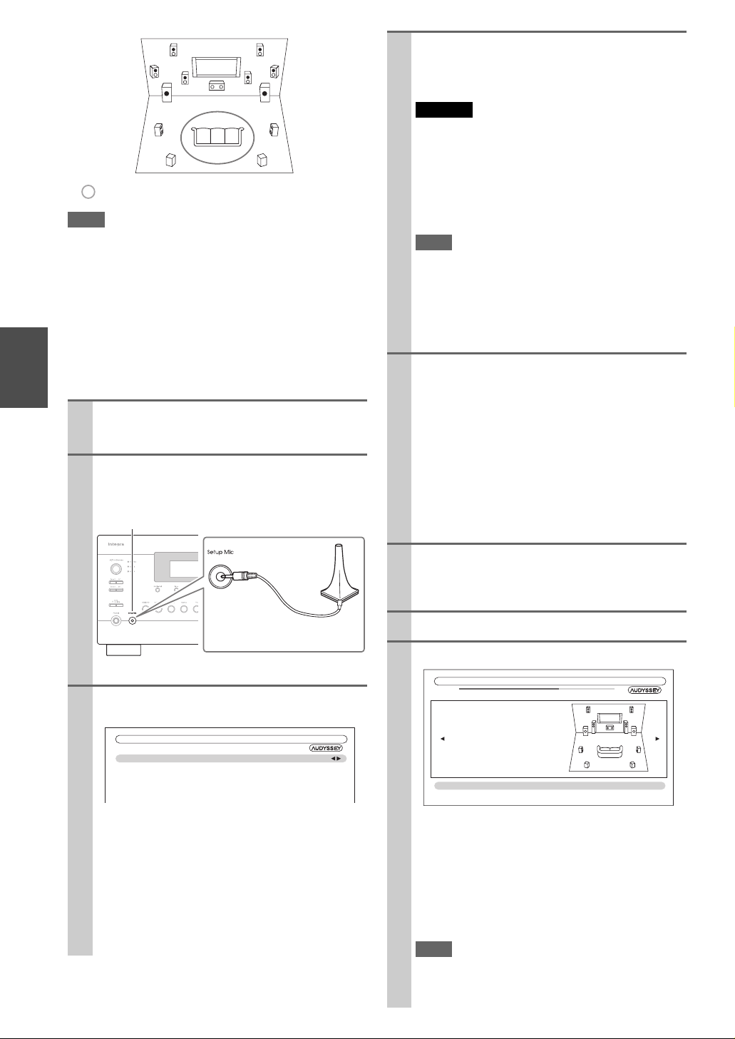
TV
de
f
cab
gh
: Listening area
Note
• Make the room as quiet as possible. Background noise and Radio
Frequency Interference (RFI) can disrupt the room measurements. Close windows, televisions, radios, air conditioners, fluorescent lights, home appliances, light dimmers, or other
devices. Turn off the cell phone (even if it is not in use) or place
it away from all audio electronics.
• The microphone picks up test tones which played through each
speaker as Audyssey MultEQ
Speaker Setup run.
• Audyssey MultEQ XT32 Room Correction and Speaker Setup
cannot be performed while a pair of headphones is connected.
Turn on the AV controller and the connected TV.
1
a to h: Listening position
®
XT32 Room Correction and
On the TV, select the input to which the AV controller is connected.
Set the speaker setup microphone at the Main Lis-
2
tening Position a, and connect it to the Setup
Mic jack.
Setup Mic jack
Speaker setup microphone
The speaker setting menu appears.
When you’ve finished making the settings, press
3
Enter.
MultEQ XT32: Auto Setup
Speakers Type(Front)
Front High + Front Wide
Front High / Front Wide Preout
Subwoofer
• If you change “Speakers Type(Front)” or “Front
High + Front Wide” setting, refer to “Speaker Set-
tings” for more details (➔ 54).
• In accordance with the connected speakers, set the
“Front High / Front Wide Preout” setting to
“Front High” or “Front Wide”.
• If you are using a subwoofer(s), select “1ch” or
“2ch” in the “Subwoofer” (➔ 54). If not, select
“No” and skip step 4.
En
30
Normal
No
Front High
1ch
If you use a powered subwoofer(s), adjust the sub-
4
woofer volume level to 75dB.
Test tones are played through the subwoofer. Use the
volume control on the subwoofer.
Caution
• When the “Subwoofer” setting is set to “1ch”, the
left-hand subwoofer (SW1) alone will be measured.
When the “Subwoofer” setting is set to “1ch” with two
subwoofers connected, the right-hand subwoofer (SW2)
will not be measured and no sound will be output.
• An error will occur if you set “Subwoofer” to “2ch” without connecting any subwoofers, or with only one subwoofer connected.
Note
• If your subwoofer does not have a volume control, disregard the level displayed and press Enter to proceed to the
next step.
• If you set the subwoofer’s volume control to its maximum
and the displayed level is lower than 75 dB, leave the subwoofer’s volume control at its maximum and press Enter
to proceed to the next step.
Press Enter.
5
Audyssey MultEQ XT32 Room Correction and
Speaker Setup starts.
Test tones are played through each speaker as
Audyssey MultEQ XT32 Room Correction and
Speaker Setup runs. This process takes a few minutes. Please refrain from talking during measurements and do not stand between speakers and the
microphone.
Do not disconnect the speaker setup microphone during Audyssey MultEQ XT32 Room Correction and
Speaker Setup, unless you want to cancel the setup.
Place the setup microphone at the next position,
6
and then press Enter.
Audyssey MultEQ XT32 performs more measurements. This takes a few minutes.
When prompted, repeat step 6.
7
Use q/w to select an option, and then press Enter.
8
MultEQ XT32: Auto Setup
Subwoofer 2ch
Front 40Hz
Center 40Hz
Surround 100Hz
Front Wide None
Front High 100Hz
Surround Back 120Hz
Surround Back Ch 2ch
Save
Cancel
- - Review Speaker Configuration - -
TV
The options are:
` Save:
Save the calculated settings and exit
Audyssey MultEQ XT32
Speaker Setup
.
Room Correction and
` Cancel:
Cancel Audyssey MultEQ XT32 Room Correc-
tion and Speaker Setup
Note
• You can view the calculated settings for the speaker configuration, speaker distances, and speaker levels by using
e/r.
.
 Loading...