

Page 1
®
CROMA24
COLOR PRINTER
SERVICE MANUAL
Page 2

This Page Intentionally Left Blank
Page 3

®
Croma24™
COLOR INKJET
PRINTER
SERVICE MANUAL
Part Number 208817
Page 4

Croma24 Service Manual
Copyright © 1995 and 1996 ENCAD®, Inc. All rights
reserved.
ENCAD is a registered trademark of ENCAD, Inc.
CROMA24™ is a trademark of ENCAD, Inc.
Other trademarks and registered trademarks are the
property of their respective owners.
No part of this manual may be copied or distributed,
transmitted, transcribed, stored in a retrieval system, or
translated in any human or computing language, in any
form or by any means, electronic, mechanical, magnetic or otherwise, or disclosed to a third party without
the express written permission of ENCAD, Inc., 6059
Cornerstone Court West, San Diego, CA 92121, U.S.A.
Printing history
1st Edition Rev A May 1997
4
Page 5

FCC Statement (U.S.A.)
The United States Federal Communications Commision has specified
that the following notice be brought to the attention of the users of the
Croma24 printers.
FEDERAL COMMUNICATIONS COMMISION RADIO AND TELEVISION INTERFERENCE FOR CLASS B DEVICE
This equipment has been tested and found to comply with the limits for a
class B digital device, pursuant to part 15 of the FCC Rules. These
limits are designed to provide reasonable protection against harmful
interference in a residential installation. This equipment generates,
uses, and can radiate radio frequency energy and, if not installed and
used in accordance with the instructions, may cause harmful interference to radio communications.
User Instructions:
If the equipment does cause harmful interference to radio or television
reception, which can be determined by turning the equipment off and on,
the user is encouraged to try to correct the interference by one of the
following measures:
Croma24 Service Manual
• Reorient or relocate the receiving antenna.
• Increase the separation between the equipment and receiver.
• Connect the equipment into an outlet on a circuit different from
that to which the receiver is connected.
• Consult the dealer or an experienced radio/TV technician for
help.
Changes or modifications not expressly approved by ENCAD, Inc. could
void the user’s authority to operate the equipment.
5
Page 6

Croma24 Service Manual
VDE Statement
Hiermit wird bescheinigt, daß der
den Bestimmungen der BMPT-AmstbIVfg 234/1991 funkentstört ist. Der
vorschriftsmäßige Betrieb mancher Geräte (z.B. Meßsender) kann
allerdings gewissen Einschränkungen unterliegen. Beachten Sie
deshalb die Hinweise in der Bedienungsanleitung.
Dem Zentralamt für Zulassungen im Fernmeldewesen würde dan
Inverkehrbringen dieses Gerätes angezeigt und die Berechtigung zur
Überprüfung der Serie auf die Einhaltung der Bestimmungen
eingeräumt.
ENCAD, Inc.
U.S.A
CROMA24
in Übereinstimmung mit
6
Page 7

Material Safety Data Sheet
Croma24 Service Manual
CROMA24
no special disposal handling. It can be harmful if swallowed and should
be kept away from children.
To obtain a Material Safety Data Sheet, contact
International users should contact their local dealer or distributor.
QIS (Quality Image Supplies) ink is nonhazardous, requiring
ENCAD, Inc.
6059 Cornerstone Court West
San Diego, CA 92121-3734
(619) 452-4350
at:
7
Page 8

Croma24 Service Manual
WARRANTY OR DAMAGE CLAIMS
United States
ENCAD®, Inc., warrants its printers ("PRODUCT") to be free from defects in workmanship
and materials for a period of one year from the date of purchase. In order to submit a
Warranty claim, please contact the ENCAD Help Desk at (619) 452-4350.
ENCAD reserves the right to make changes or improvements to Products, without
incurring any obligation to similarly alter Products previously purchased.
Buyer's sole and exclusive rights pursuant to this Warranty shall be for the repair or
replacement of defective Product. ENCAD specifically disclaims any and all other
warranties, expressed or implied, including but not limited to, implied warranties of
merchantability and fitness for a particular purpose. In no event shall ENCAD be liable
for any loss of profit or other commercial damages, special, incidental or consequential
damages, or any other damages or claims, whatsoever.
This Warranty gives Buyer specific legal rights, and Buyer may also have other rights
that vary from state to state.
This Warranty applies only to printers purchased from ENCAD, or authorized ENCAD
distributors or dealers. The intent of this Warranty is to repair or replace defective
Products subjected to normal wear and tear, when operated according to ENCAD
instructions.
This Warranty does not cover damage to the Product resulting from the following:
• Accident or negligence.
• Unauthorized modification of the Product.
• Adverse environmental conditions.
• Service of the Product by other than an ENCAD authorized service provider.
• Unauthorized or improper use, including but not limited to:
– Use in applications for which the Product was not designed.
– Using cartridges or ink other than those supplied by ENCAD or authorized
ENCAD resellers.
– Using media other than that supplied by ENCAD or authorized ENCAD
resellers.
– Lubricating any part of the printer.
Internationally: Contact your dealer or distributor for warranty information.
8
Page 9

Croma24 Service Manual
Table of Contents
Chapter 1 General Description............................................................. 17
Introduction ...............................................................................................................17
Overview ...................................................................................................................18
Related Publications ...........................................................................................18
Electrostatic Discharge (ESD) Sensitivity ..................................................................18
Warnings, Cautions, and Notes.................................................................................19
Printer Specifications ................................................................................................20
Contents of this Service Manual................................................................................21
Technical Support .....................................................................................................2 3
Chapter 2 Theory of Operation............................................................. 25
Introduction ...............................................................................................................25
Croma24 Printer General Block Diagram ..................................................................25
Paper (Media) Axis Drive ..........................................................................................27
The Carrier Axis Drive...............................................................................................28
Main Printed Circuit Board (MPCB)...........................................................................29
Microprocessor ...................................................................................................3 0
Gate Array ..........................................................................................................3 0
Memory Circuits..................................................................................................31
Stepper Motor Controller.....................................................................................33
Servo Motor Controller........................................................................................34
Interface Circuits: Serial & Parallel......................................................................36
Carrier Assembly Circuits..........................................................................................37
Power Supply............................................................................................................38
System Grounding ....................................................................................................38
Front Key Controls ....................................................................................................40
Chapter 3 Maintenance ......................................................................... 43
Introduction ...............................................................................................................43
Scheduled Maintenance............................................................................................43
Cleaning Procedures ..........................................................................................44
External Cleaning .........................................................................................44
Slide Shaft Cleaning.....................................................................................44
9
Page 10

Croma24 Service Manual
Table of Contents (cont)
Chapter 3 Maintenance (cont)
Service Station Cleaning ..............................................................................45
Linear Encoder Strip Cleaning......................................................................46
Cartridge Dimple Cleaning ...........................................................................47
Flex Cable Contact Cleaning........................................................................48
Clean and Inspect Stepper Motor Gears ......................................................48
Clean and Inspect MPCB .............................................................................49
Clean and Inspect Carrier Assembly ............................................................49
Reseat Connectors on MPCB and Carrier Board................................................50
Replace Carrier Bushings...................................................................................52
Servo Motor Winding Resistance Check...................................................................52
Stepper Motor Winding Resistance Check................................................................53
Banding: Hardware vs Software................................................................................53
Alignments/Adjustments............................................................................................55
Color Calibration .................................................................................................55
Deadband Alignment ..........................................................................................56
X-Axis Calibration ...............................................................................................57
Pinch Roller Adjustment Procedure ....................................................................57
Head Height Alignment Procedure......................................................................60
Croma24 Control Panel.............................................................................................65
Manufacturing Menu ...........................................................................................66
Print Quality T est..........................................................................................67
Deadband.....................................................................................................67
Diagnostics Menu ...............................................................................................68
Paper Sensor Test........................................................................................69
Fan Test .......................................................................................................69
Carriage Vibration Test.................................................................................70
Color Test .....................................................................................................70
Keypad Test .................................................................................................71
LED Test ......................................................................................................72
Servo Motor Test ..........................................................................................72
Paper Motor Test..........................................................................................73
Service Menu......................................................................................................74
Built In Test (BIT) ......................................................................................................75
10
Page 11

Croma24 Service Manual
Table of Contents (cont)
Chapter 3 Maintenance (cont)
Firmware/Software Upgrades....................................................................................76
Internal Cabling and Signal Flow Diagram ................................................................77
Chapter 4 Troubleshooting................................................................... 79
Introduction ...............................................................................................................79
No Power ..................................................................................................................79
Media Does Not Move...............................................................................................80
Carrier Axis Failure ...................................................................................................81
Does Not Print...........................................................................................................82
Ink Cartridge Misfiring ...............................................................................................82
Paper Skewing ..........................................................................................................83
Printer Output is Banding ..........................................................................................84
Fan Does Not Power Up ...........................................................................................85
Chapter 5 Assembly\Disassembly ....................................................... 87
Introduction ...............................................................................................................87
Remove the Left, Middle (Lid), and Right Covers......................................................88
Install the Left, Middle, and Right Covers ..................................................................89
Remove the MPCB (Main Printed Circuit Board) and Actuator Assembly .................90
Install the MPCB and Actuator Assembly ..................................................................91
Remove Servo Motor ................................................................................................92
Install Servo Motor ....................................................................................................94
Remove the Carrier Assembly, Carrier Belt, and the Frame T ensioner .....................95
Install the Carrier Assembly, Carrier Belt, and the Frame Tensioner ........................98
Remove the Carrier PCB ........................................................................................100
Install the Carrier PCB ............................................................................................102
Remove the Paper Sensor or the Encoder Sensor .................................................102
Install the Paper Sensor or the Encoder Sensor .....................................................104
Remove the Trailing Cable Cover Assembly ...........................................................105
Install the Trailing Cable Cover Assembly ...............................................................107
Replacing the Carrier Bushings...............................................................................108
Remove the Service Station, Seals, and Wipers..................................................... 110
Install the Service Station, Seals, and Wipers ......................................................... 1 11
11
Page 12

Croma24 Service Manual
Table of Contents (cont)
Chapter 5 Assembly\Disassembly (cont)
Remove the Lower Roller Assembly and Stepper Motor ......................................... 112
Install the Lower Roller Assembly and Stepper Motor ............................................. 115
Remove the Power Supply and AC Entry Module ...................................................117
Install the Power Supply and AC Entry Module .......................................................120
Chapter 6 Parts List ............................................................................ 123
Index..................................................................................................... 131
12
Page 13

Croma24 Service Manual
List of Illustrations
Figure Page
Chapter 1 General Description
Chapter 2 Theory of Operation
2-1. General Block Diagram ...................................................................................26
2-2. Paper (Media) Axis Drive.................................................................................27
2-3. Carrier Axis Drive ............................................................................................28
2-4. Main Printed Circuit Board...............................................................................29
2-5. Gate Array.......................................................................................................30
2-6. Stepper Motor Controller .................................................................................33
2-7. Servo Motor Controller ....................................................................................34
2-8. Quadrature Signal Generation.........................................................................35
2-9. Interface Circuits .............................................................................................36
2-10. Carrier Assembly Circuits ................................................................................37
2-11. Croma24 System Ground Network (Left Side) ................................................39
2-12. Croma24 System Ground Network (Right Side) ..............................................40
2-13. Front Key Controls...........................................................................................40
Chapter 3 Maintenance
3-1. Encoder Strip Cleaning....................................................................................46
3-2. Cartridge Dimple Region .................................................................................47
3-3. Flex Cable Contacts ........................................................................................48
3-4. MPCB Connection Locations...........................................................................50
3-5. Carrier PCB Connection Locations ..................................................................51
3-6. Ribbon Connector Locking Mechanism ...........................................................51
3-7. Servo Motor.....................................................................................................52
3-8. Stepper Motor..................................................................................................53
3-9. Examples of Banding ......................................................................................54
3-10. Color Calibration ..............................................................................................55
3-1 1. Deadband Fast/Slow .......................................................................................56
3-12. Upper Roller Support Description ....................................................................57
3-13. Upper Roller Mounting.....................................................................................59
3-14. Gap of Pinch Roller .........................................................................................59
3-15. Upper Roller Adjustment .................................................................................60
3-16. Carrier Head Height Tolerance........................................................................61
13
Page 14

Croma24 Service Manual
List of Illustrations (cont)
Figure Page
Chapter 3 Maintenance (cont)
3-17. Setting Up Tools from Height Gauge Kit..........................................................61
3-18. Zeroing the Micrometer Gauge........................................................................62
3-19. Test Cartridge Installed....................................................................................62
3-20. Carrier Positions for Head Height Adjustment .................................................63
3-21. Maintenance Menu ..........................................................................................66
3-22. Manufacturing Menu........................................................................................66
3-23. Deadband Options Menu.................................................................................67
3-24. Deadband Slow/Fast Display...........................................................................68
3-25. Diagnostics Menu ............................................................................................68
3-26. Paper Sensor Reported Data Dialog Box ........................................................69
3-27. Fan Test Menu Panels.....................................................................................69
3-28. Color Test........................................................................................................70
3-29. Keypad T est.....................................................................................................71
3-30. LED Test..........................................................................................................72
3-31. Servo Motor Test.............................................................................................72
3-32. Paper Motor Test.............................................................................................73
3-33. Service Menu ..................................................................................................74
3-34. ROM Info .........................................................................................................74
3-35. Service Special Information .............................................................................75
3-36. Signal Wiring Diagram.....................................................................................78
Chapter 4 Troubleshooting
Chapter 5 Assembly/Disassembly
5-1. Cover Removal/Installation..............................................................................89
5-2. Frame Tensioner .............................................................................................92
5-3. Electronics Cover Removal .............................................................................95
5-4. Strain Relief Removal/Installation from Carrier................................................96
5-5. Carrier Belt Clamp...........................................................................................97
5-6. Installation of Frame Tensioner .......................................................................99
5-7. Carrier PCB Removal/Installation ..................................................................101
5-8. Paper and Encoder Sensor Removal ............................................................103
5-9. Paper and Encoder Sensor Installation .........................................................104
14
Page 15

Croma24 Service Manual
List of Illustrations (cont)
Figure Page
Chapter 5 Assembly/Disassembly (cont)
5-10. Trailing Cable Assembly Removal/Installation ...............................................106
5-11. Carrier Bushing Removal ..............................................................................108
5-12. Carrier Bushing Installation............................................................................109
5-13. Service Station, Exploded View .....................................................................110
5-14. C-Bracket Assembly and Platen Removal ..................................................... 113
5-15. Stepper Motor Removal/Installation............................................................... 114
5-16. Installing Lower Roller Assembly ...................................................................116
5-17. Ground Stud with Ground Lugs Attached ......................................................118
5-18. Power Supply Assembly ................................................................................119
Chapter 6 Parts List
6-1. Croma24 Assembly Parts (Platen and Above)...............................................125
6-2. Croma24 Assembly Parts (Below Platen)......................................................126
6-3. Carrier Assembly Breakdown ........................................................................127
6-4. C-Bracket Assembly Breakdown ...................................................................128
6-5. Lower Roller Assembly Breakdown ...............................................................129
15
Page 16

Croma24 Service Manual
List of Tables
Table Page
Chapter 1 General Description
Chapter 2 Theory of Operation
2-1. Front Key Control LED Codes .........................................................................41
Chapter 3 Maintenance
3-1. Pinch Roller Adjustments ................................................................................58
3-2. Keypad Test Indications...................................................................................71
Chapter 4 Troubleshooting
4-1. Troubleshooting Table .....................................................................................79
Chapter 5 Assembly/Disassembly
Chapter 6 Parts List
6-1. Parts List .......................................................................................................123
16
Page 17

General Description
Introduction
This manual provides service information for the ENCAD, Inc.
Croma24 Color Inkjet Printer.
There are three versions to the Croma24 Color Inkjet Printer
family:
CAD version GA & CAD version GA version
for: CAD market GA & CAD GA
I/O: parallel serial & parallel serial & parallel
includes: ENCAD software RIP
All versions will have an ADI Windows driver and print utility.
This manual is written for service personnel who possess analog
and digital circuitry experience. Chapter 2, Theory of Operation,
should be read and thoroughly understood before troubleshooting/
calibrating the printers.
The printers support pre-cut and roll media. Media size is automatically determined and hardclip limits are set accordingly. Precut media uses different maximum plotting areas than roll media.
See the Printer Specifications for more details.
1
DESCRIPTION
GENERAL
Both RS-422 serial and Centronics parallel connections are provided to interface with the host computer on the GA (Graphic Arts)
compatable versions. Only the Centronics parallel connection
exists on the CAD only version. Commands sent from the host
computer are in Encad RTL format.
Drivers are supplied to support Windows-based PC’s (3.XX, 95, and
NT) as well as Macintosh and Power PC computers.
These printers expand upon ENCAD’s tradition of delivering fast,
high-quality color or monochrome graphics for a variety of applications. ENCAD has made significant advances in designing these
17
Page 18

Croma24 Service Manual
plotters to respond to and anticipate our customers’ needs. Principal
features are summarized below.
Three Versions: CAD, GA (Graphic Arts), GA & CAD
ENCAD’s software RIP supplied with the GA (Graphic Arts) version
Remotely Configured via Host Computer
25" (63.6 cm) Maximum Media Width
600 x 600 dpi (mono) addressable
300 x 300 dpi (color)
Overview
Printers draw according to instructions issued from a “host” computer. Every printer is engineered to understand a specific set of
instructions and to execute each instruction in a precise manner.
In addition, most printers are designed to execute predetermined
characters automatically without a specific line-by-line instruction
from the program. These characters are part of the printer’s
permanent memory.
Related Publications
The following publication contains additional information which may
be useful in servicing the ENCAD, Inc. Croma24 Color Inkjet
Printers:
• ENCAD, Inc. Croma24 User Guide, P/N 207103
Copies of this and other ENCAD, Inc. publications may be obtained
by contacting your nearest authorized ENCAD, Inc. dealer or by
contacting ENCAD’s Technical Support and Service Department.
Electrostatic Discharge (ESD) Sensitivity
All PCBs (Printed Circuit Boards) associated with the Croma24
printers have components sensitive to ESD (electrostatic discharge). Care must be taken to avoid damage to any of the components by following current ESD handling procedures and practices.
Always use an approved ESD grounding strap when handling or
working with PCBs.
18 General Description
Page 19

Croma24 Service Manual
W arnings, Cautions, and Notes
Warnings, cautions, and notes are used when additional information, instructions, or care should be observed. In this manual,
warnings cautions, and notes precede the text to which each applies. The definition of each is provided below.
WARNINGS - Warnings are used to stress that the following steps
or procedure has the potential to cause serious harm or death to
service personnel. Extreme care should be observed when following
the procedures and to exercise standard safety procedures. They
are indicated by:
Followed by a paragraph describing the concern.
CAUTION - Cautions depict that the following steps or procedures
can cause damage to the equipment if not properly followed. Extreme care should be observed when following the procedures and
to exercise standard safety procedures. They are indicated by:
DESCRIPTION
GENERAL
Followed by a paragraph describing the concern.
NOTE - Notes are placed before a procedure to inform the service
personnel of specific details to improve quality, to give reminders of
interrelated parts, and to provide other helpful information. They
are indicated by:
NOTE
Followed by a paragraph describing the concern.
General Description 19
Page 20

Croma24 Service Manual
Printer Specifications
The specifications and performance characteristics of the Croma24
Color Inkjet Printers are as follows:
Max Printing Area:
Norm 23.8” 60.9cm
Extend 24.6” 62.9cm
Language Emulation:
ENCAD RTL
Buffer:
2 MB permanently
installed
(not upgradable)
Power Requirements:
Input Voltage:
90 - 246 VAC
47 - 63 Hz
Output Power:
24 W typical
63 W maximum
Baud Rates:
38400
1MByte High Speed
Serial (MAC only)
Resolution:
Mono 600x600 dpi
addressable
Color 300x300 dpi
Accuracy:
0.2% line length (with
ROLL mode off)
Interface:
Centronics parallel
RS-422 serial
(GA and GA/CAD
versions only)
Environment:
Operating:
41° to 104° F
(5° to 40° C)
10% to 70% RH
non-condensing
Storage:
-40° to 140° F
(-40° to 60° C)
5% to 80% RH
non-condensing
Dimensions:
Height 12” (305mm)
Width 43.5” (1105mm)
Dept h 14” (356mm)
20 General Description
Page 21

Croma24 Service Manual
Contents of this Service Manual
Figures are used in this manual to clarify procedures. They are
for illustrative purposes only and may not necessarily be drawn to
scale.
Material in this manual may be repeated in various sections so
that each section can “stand alone”. This allows information to be
located without having to refer back and forth between sections.
Figures and tables are easily located and cross-referenced, and are
listed in the front of the manual under List of Illustrations and
List of Tables.
This manual is divided into six chapters as:
Chapter 1 GENERAL DESCRIPTION - Contains a general
description of the ENCAD Croma24 printer. This
includes printer specifications, and related materials.
Also included is a description of the use of Warnings,
Cautions and Notes as used in this manual and chapter
contents.
Chapter 2 THEORY OF OPERATION - Functional
descriptions of the overall printer and major assemblies
are contained in this chapter.
DESCRIPTION
GENERAL
Chapter 3 MAINTENANCE - This chapter covers the
scheduled maintenance, cleaning procedures and
alignment/adjustments recommended to perform on the
printers. Diagnostics and a signal flow diagram are also
listed.
General Description 21
Page 22

Croma24 Service Manual
ORIENTATION - Instructions in this manual are based on the
assumption that the service person is facing the front of the
printer. References to top view, back view, and so forth are consistent with this engineering standard. References to the X Axis and
Y Axis (Paper Axis and Carrier Axis, respectively) follow the standard of AutoCAD™ absolute coordinates: up and down for X, left
to right for Y.
Chapter 4 TROUBLESHOOTING - A table containing
problems that could occur and possible causes and repairs
is found in this chapter. This table is not intended to be a
complete listing of troubleshooting procedures. It will
isolate the problem down to the lowest replacable
assembly. If the problem happens to be the wiring
between assemblies, standard troubleshooting techniques
will have to be implemented to correct the problem.
Chapter 5 ASSEMBLY/DISASSEMBLY - Contains detailed
procedures to remove and replace printer parts and
assemblies.
Chapter 6 PARTS LIST - Contains a complete listing of all
field replacable parts and assemblies for the Croma24
Color Inkjet Printer. Illustrated parts breakdown
drawings are included to help clarify and identify parts for
ordering. Special kits and adjustment jigs may be
required.
22 General Description
Page 23

Croma24 Service Manual
T echnical Suppor t
ENCAD offers full technical support and service for its various
products. If you are unable to find the answer to your question in
either the User’s Guide, Service Manual, or other related publications, check out ENCAD’s Technical Bulletins located on
ENCAD’s bulletin board or the Internet:
ENCAD BBS: (619) 452-2653 or
ENCAD Website: http://www.encad.com
Additional information is available though our Technical Support
and Service Department’s Help Desk.
ENCAD, Inc.
Technical Support & Service Dept.
6059 Cornerstone Court West
San Diego, CA 92121
Help Desk Telephone: (619) 452-4350
Help Desk FAX: (619) 546-0659
DESCRIPTION
GENERAL
(619) 452-3768
International Users contact your local ENCAD service provider.
see details on your ENCAD registration card.
General Description 23
Page 24

Croma24 Service Manual
This Page Intentionally Left Blank
24 General Description
Page 25

Theory of Operation
Introduction
This chapter explains the mechanical and electrical theory of operation of the ENCAD Croma24 D-Size Color Inkjet printer.
The Croma24 is a MC68322 microprocessor-based digital printer
that receives plotting instructions from a host computer through
either the RS-422 serial interface or the Centronics parallel interface.
Croma24 Printer General Block Diagram
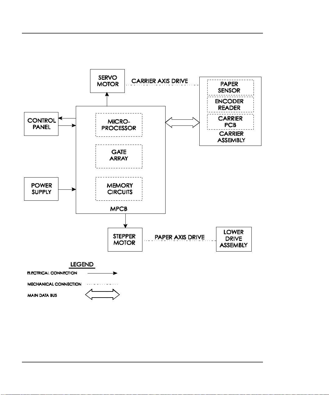
Figure 2-1 illustrates the major functional areas of the printer.
The Croma24 printer consists of two mechanical drives:
1. Paper (Media) Axis Drive
2. Carrier Axis Drive
2
THEORY OF
OPERATION
and three main electrical assemblies:
1. MPCB (Main Printed Circuit Board)
2. Carrier Assembly
3. Power Supply
25
Page 26
Croma24 Service Manual
Figure 2-1. General Block Diagram.
26 Theory of Operation
Page 27
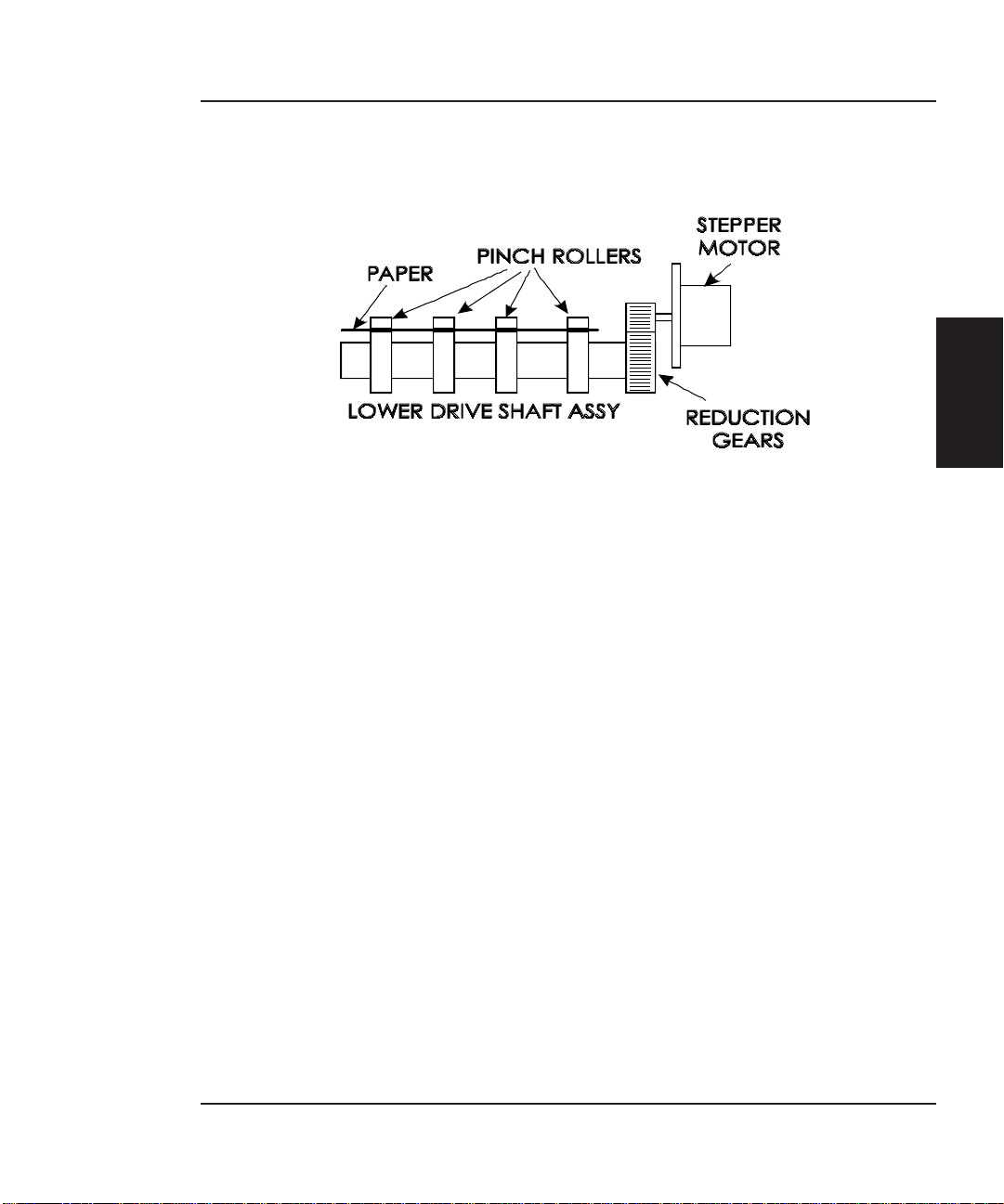
Paper (Media) Axis Drive
Figure 2-2. Paper (Media) Axis Drive.
The Paper (Media) Axis Drive moves the plotting media in a direction perpendicular to the length of the printer. This friction drive
utilizes a micro-step drive technology and consists of a stepper
motor, reduction gears, lower drive shaft assembly, and pinch
wheels. This can be seen in Figure 2-2.
Croma24 Service Manual
THEORY OF
OPERATION
The micro-step technology associated with the stepper motor gives
the capability of a resolution up to 600 dpi.
The reduction gear meshes the stepper motor to the lower drive
shaft assembly which allows the media to advance or retract.
The purpose of the pinch wheels is to apply pressure to the media
onto the drive shaft assembly to reduce the chance of slipping.
Misaligned pinch wheels is the main cause of skewing of the media.
Theory of Operation 27
Page 28

Croma24 Service Manual
The Carrier Axis Drive
Figure 2-3. Carrier Axis Drive.
The Carrier Axis Drive moves the printer’s carrier assembly along
the length of the printer. The drive consists of a servo motor, linear
encoder strip, drive belt, and tension assembly. These items are
illustrated in Figure 2-3.
The servo motor, drive belt, and tension assembly are the components that actually drive the carrier assembly. The servo motor
drives the belt back and forth allowing the attached carrier assembly
to be repositioned as required. The tension assembly is spring
controlled and allows the proper amount of tension on the belt.
The linear optical encoder strip is used to obtain the printers accuracy along the axis of the printer. It is made with 150 parallel lines
per inch etched into it. By utilizing two optical encoder sensors that
are slightly off set from each other, and reading the leading and
trailing edges of the lines, a resolution of 600 dpi can be obtained.
The stepper and servo motors are controlled from the main printed
circuit assembly by the microprocessor.
28 Theory of Operation
Page 29
Main Printed Circuit Board (MPCB)
Croma24 Service Manual
THEORY OF
OPERATION
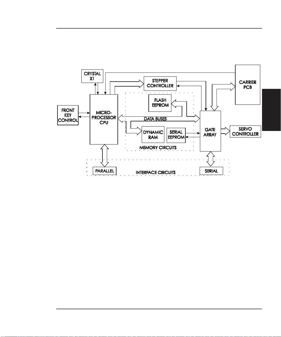
Figure 2-4. Main Printed Circuit Board.
The Main Printed Circuit Board (MPCB) consists of six functional
areas:
1. Microprocessor (CPU)
2. Gate Array
3. Memory Circuits
4. Stepper Motor Controller
5. Servo Motor Controller
6. Interface Circuits: Serial & Parallel
Theory of Operation 29
Page 30
Croma24 Service Manual
Microprocessor
The microprocessor (a Motorola MC68322) is the central processor
unit which supervises system functions, executes the printer firmware, manipulates data, and controls input/output data busses. It
has a built-in parallel port, a two channel DMA (Direct Memory
Access) controller, timer module, clock generator, and an on-board
chip select generator. One DMA channel supplies data to the gate
array for jet firing; the other DMA channel is used to receive data
through the serial port via the gate array, or the serial port when
using a high speed serial mode. One timer generates a servo interrupt every millisecond.
The microprocessor halves the 40MHz crystal reference (X1) signal
to create the 20MHz system clock that is used for timing of all
internal circuitry.
The chip select generator is programmed to generate chip selects at
the appropriate addresses, with the appropriate data size (byte,
word) and with the appropriate number of wait states.
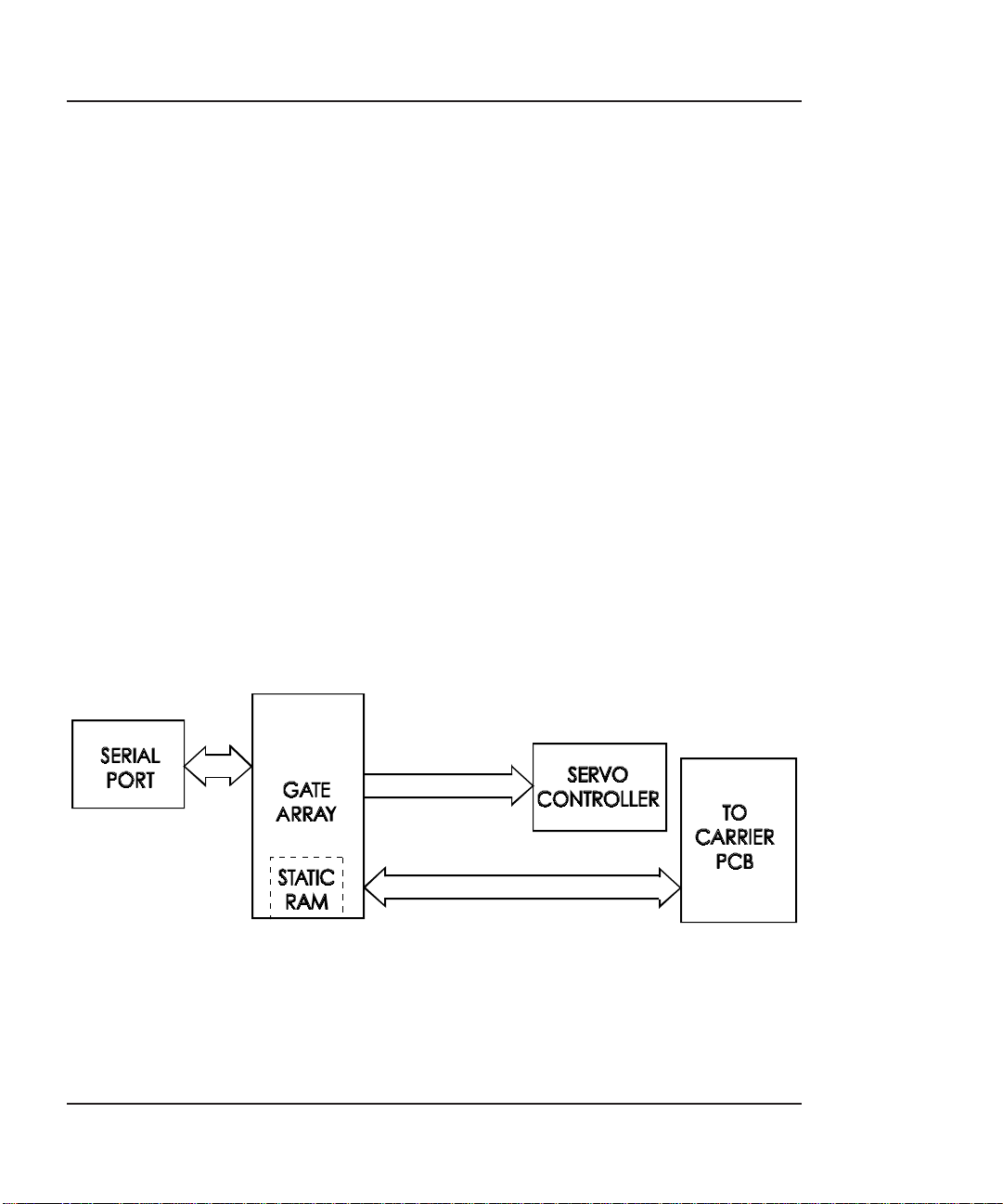
Gate Array
30 Theory of Operation
Figure 2-5. Gate Array.
Page 31

The gate array contains the hardware logic for dot firing, monitoring changes in the Carrier Assembly position, controlling DMA for
the serial port, and generating the PWM (Pulse Width Modulation)
waveforms for the servo controller.
The gate array is a Xilinx device. It is a static RAM-based field
programmable gate array. This means that the logic that it implements is determined by configuration information in internal RAM
storage. Each time power is turned on, this information must be
downloaded from the system ROM. This type of gate array allows
for the flexibility of upgrading the logic by simply downloading the
new system software.
Memory Circuits
Memory is used to retain large amounts of information. This
information is stored in the device memory in the form of binary
bits.
Printer memory consists of Flash EEPROM, DRAM, and
EEPROM.
Croma24 Service Manual
THEORY OF
OPERATION
Maximum installable memory is as follows:
DRAM = 2 MB
Flash EEPROM = 1 MB
Serial EEPROM = 1 KB
Flash EEPROM
Flash EEPROM is Electrically Erasable, Programmable, Read Only
Memory used to store instructions and data constants which the
microprocessor can access and interpret. This set of instructions
and data constants is called the “firmware” of the plotter.
The term “Flash” means that bytes cannot be individually erased.
A block or the whole device is erased at the same time and the
block or whole device is then reprogrammed. It can be erased and
reprogrammed more than 10,000 times.
Theory of Operation 31
Page 32

Croma24 Service Manual
The system firmware is stored in Flash EEPROM and can be upgraded by opening the Control Panel located on the host computer.
Once the Control Panel has been executed, it first starts an initialization and status communication sequence with the printer. The
Control Panel requires ink levels and deadband information to load
correctly. At the same time, it checks the version of firmware that is
loaded on the printer.
The flash EEPROM is a volitile memory in that it will lose updated
information after a loss of power and revert back to the firmware
that was initially installed at the factory. If the Control Panel
contains a newer version of the firmware than the printer is currently loaded with, it automatically updates the firmware at the
startup of the Control Panel.
DRAM
DRAM is Dynamic Random Access Memory which provides temporary storage of the microprocessor calculation and input/output data.
It is also a faster type of memory then the Flash EEPROM. Thats
why the printer control program is also copied from the Flash
EEPROM to RAM, where it can be executed faster.
The printer is supplied with 2 Megabytes of DRAM permanently
installed on the Main PC Board. Memory expansion is not available
for this printer. Since it only supports EN-RTL language, additional
memory is not required or beneficial.
Serial EEPROM
Serial EEPROM is an Electrically Erasable, Programmable, Read
Only Memory which provides storage for calibration constants and
user configuration data entered from the host computer.
A 1K bit serial nonvolatile EEPROM stores calibration and configuration information. It retains data while the unit is off.
32 Theory of Operation
Page 33

Stepper Motor Controller
Croma24 Service Manual
Figure 2-6. Stepper Motor Controller.
The media is driven by a Stepper Motor, which drives the media in
a direction perpendicular to the length of the printer. The media
in the printer can advance forward and backward, depending upon
the commands which the Stepper Motor receives from the microprocessor.
The Stepper Motor Controller contains two identical circuits, one
for each winding of the stepper motor. The circuit is a combination
of two simpler types of circuits and can be thought of as a variation
of either one.
A digital-to-analog (D/A) converter receives digital data from the
CPU and generates a sine wave output. This signal is fed into a
comparator circuit that measures the current through the winding
of the stepper motor. If the current is too low, a pulse of 24 V is
generated. When the current goes above the output of the waveform generator, the pulse turns off. Every time the output of the
waveform generator is changed by the microprocessor, the motor
moves 1 “micro-step”.
Each circuit contains four main blocks (see Figure 2-6):
1. Reference waveform generator
THEORY OF
OPERATION
The microprocessor uses a D/A (digital to analog) converter to
set the desired level for the current in the stepper motor
winding. The output of the D/A converter varies in time to
create a reference waveform. This reference waveform is
centered around 10 V.
Theory of Operation 33
Page 34

Croma24 Service Manual
2. Motor current sense
The voltage across a series current sense resistor is measured
and level shifted so that it is centered around 5 V.
3. Comparator
This portion divides the output of the reference waveform gen-
erator by two and compares it to the output of the motor current
sensor. Logic inside the gate array generates the control signals
for the power driver that applies voltage across the motor winding in order to make the actual current match the reference
waveform.
4. Power driver
An H-bridge allows the supply voltage to be applied across the
winding in either polarity to drive the current to the desired
value.
Servo Motor Controller
Figure 2-7. Servo Motor Controller.
The Carrier Assembly is driven by the Servo Motor. The speed of the
Carrier Assembly is controlled by varying the duty cycle of the power
applied to the controller. The microprocessor checks the position of
the Carrier Assembly approximately 1,000 times per second (during
the servo interrupt). It then updates the PWM (pulse width modula-
34 Theory of Operation
Page 35

Croma24 Service Manual
tor) register in the gate array which sets the duty cycle to make
adjustments to the Carrier Assembly speed. A linear optical encoder
is used to monitor the Carrier Assembly position.
The optical encoder strip runs the length of the Stabilizer Bracket
and contains 150 lines and spaces per inch. Thus there are 300
edges per inch. The detector circuit actually consists of two optical
edge detectors. They are separated from each other by one half the
width of one of the optical lines on the encoder strip. This allows 4
evenly spaced pulses to be developed for each line on the encoder
strip. This is known as quadrature signals. It gives an effective
resolution of 600 lines per inch. See Figure 2-8 for a graphical
representation of quadrature signals.
THEORY OF
OPERATION
Figure 2-8. Quadrature Signal Generation.
Theory of Operation 35
Page 36

Croma24 Service Manual
The direction that the Carrier Assembly is moving is known based
upon the state of one detector’s output and the direction of the
transition of the other detector’s output.
A hardware counter in the gate array increments as the Carrier
Assembly moves left and decrements as the Carrier Assembly moves
right. The hardware counter is only eight bits wide, so it cannot
store a value large enough to represent an absolute Carrier Assembly
position. Instead, it is read during the servo interrupt and its value
compared with that from the previous interrupt. This difference is
used to update the absolute position value in the software.
Interface Circuits: Serial & Parallel
Data from the host computer is received either through the
Centronics parallel port or the serial port (on the GA/CAD or GA
versions only). The gate array provides the control signals for DMA
transfers from the serial port to DRAM.
Figure 2-9. Interface Circuits.
The serial port is designed primarily to interface to a Macintosh
printer port. It has an eight pin Mini-DIN connector. The data
(TXD, RXD) signals meet RS-422 electrical specifications, and the
control signal (DTRCLK) meets the RS-423 electrical specifications.
The control signal can be configured as a 1 MHz clock for high speed
serial communications with a Macintosh.
The serial port is compatible with RS-422 devices when an appropriate adapter cable is used. This cable is available from ENCAD.
36 Theory of Operation
Page 37

Carrier Assembly Circuits
Croma24 Service Manual
THEORY OF
OPERATION
Figure 2-10. Carrier Assembly Circuits.
The Carrier Assembly contains:
1) Carrier PCB
2) Optical Sensors
3) Paper Sensor
4) Inkjet Cartridges
The Carrier PCB contains the logic and drive circuitry for the firing
of the inkjet cartridges. It also establishes an interface path for the
optical sensor and paper sensor to communicate with the MPCB.
The optical sensors receive their inputs from the optical encoder strip
and sends this data to the MPCB. The MPCB uses this information
to determine the horizontal position of the carrier assembly so that
accurate printing can be established.
The paper sensor circuitry senses for the presence of loaded media.
It does this automatically during the start-up and load sequences. It
Theory of Operation 37
Page 38

Croma24 Service Manual
also constantly monitors the media during printing to determine if
the media has run out.
If no paper is sensed, the paper sensor sends this information to the
MPCB, which immediately begins an ‘out of paper’ subroutine. This
subroutine starts the LEDS on the printer to blink (green blinks slow
while yellow blinks faster.) It also informs the host computer of the
situation and stops the printer from printing until more media is
loaded.
The sensor also checks for the size of the media loaded so it can
determine the proper printing parameters.
Power Supply
An internal UL recognized switching power module supplies power
for the Croma24 printer. It provides a constant 5 VDC and 24 VDC
output from input voltage in the range of 90-264 VAC. The 24 V
supply is used for: the stepper controller (which advances the
paper); the servo controller (which moves the Carrier); and power to
fire the inkjets. The 5V supplies power to the logic circuits.
The power supply is fused using a 2 A 250 V fast blow type fuse.
The outputs share a common ground which is isolated from earth
ground within the supply itself. Earth ground and DC ground are
connected external to the power supply.
The power supply will shut down under overload/short circuit conditions on any output over the full range of input voltage. Overvoltage
protection is 20%-30% above nominal for the 5 V and 24 V outputs.
System Grounding
Due to the amount of plastics used in the manufacturing of the
printer, a system of grounding the metal assemblies to each other is
required. If no common ground was in place, the potential of electric
shock could exist due to static voltage buildup on the individual
assemblies. The system grounding network ensures that all metallic
assemblies have the same ground potential. Figures 2-11 and 2-12
show how the ground straps are implemented on the printers.
38 Theory of Operation
Page 39

Croma24 Service Manual
THEORY OF
OPERATION
Figure 2-11. Croma24 System Ground Network (Left Side).
Theory of Operation 39
Page 40

Croma24 Service Manual
Figure 2-12. Croma24 System Ground Network (Right Side).
Front Key Controls
The Control Panel (see Figure 2-13) is located on the lower right side
of the printer and consists of five controls and two LED indicators.
The controls are (from left to right): Backward, Load, Forward, Cut,
and Power. Table 2-1 lists all possible indications allowed using the
LEDs and the conditions that generated that indication.
Figure 2-13. Front Key Controls.
40 Theory of Operation
Page 41

Croma24 Service Manual
Table 2-1. Front Key Control LED Codes.
THEORY OF
OPERATION
Theory of Operation 41
Page 42

Croma24 Service Manual
This Page Intentionally Left Blank
42 Theory of Operation
Page 43

Maintenance
Introduction
This chapter contains general maintenance and cleaning instructions for the Croma24 printer.
Scheduled Maintenance
Scheduled maintenance consists of a list of checks that are planned
to be performed on a regular basis or when conditions warrant it.
3
Scheduled maintenance can be thought of as preventive maintenance since its purpose is to prolong the life of the printer. It is not
intended to repair or isolate an existing problem, though it can
sometimes be helpful in detecting a condition due to a weakened
component that has not yet completely failed.
Below is a list of scheduled maintenance checks and their periodicity.
Clean external areas: weekly, or
as required
Clean slide shaft: monthly
Clean service station: biweekly
Clean encoder strip: monthly
Clean cartridge dimples: if prime fails
Clean flex cable contacts: if prime fails,
or cartridge
is replaced
Clean and inspect motor gears: annually
Clean and inspect MPCB: annually
Clean and inspect carrier assembly: annually
Reseat connectors on MPCB: annually
Reseat connectors on carrier board: annually
Replace carrier bushings: biannually
MAINTENANCE
43
Page 44

Croma24 Service Manual
Cleaning Procedures
External Cleaning
Always turn the printer OFF, remove the power cord
and the interface cable before cleaning the printer. An
electrical shock hazard may be present if these procedures are not followed.
Do not use abrasive cleansers of any sort on the surfaces of the printer. Damage to the surface may result.
The exterior surfaces of the printer may be cleaned with a soft cloth
which has been dampened. For more persistent stains, a small
amount of liquid detergent may be used. Cleaning intervals are
determined by the environment in which the printer is used.
Slide Shaft Cleaning
Use only isopropyl alcohol on the slide shaft of the
printer. Damage to the stainless steel slide shaft may
result if cleaned with water and not completely dried
off.
44 Maintenance
Page 45

Croma24 Service Manual
Printer problems can be caused by an accumulation of dirt or other
contamination on the slide shaft. This contamination may lead to
drag on the carrier. Extreme drag results in a “carrier axis failure”
fault and will stop the carrier motion. These problems may be
eliminated by maintaining and cleaning the slide shaft at intervals
determined by the environmental conditions. Do not use any
lubrication.
To clean the slide shaft:
1. Remove the power cord.
2. Raise the middle cover.
3. Moisten a clean cloth or paper wipe with isopropyl alcohol.
4. Wipe the length of the slide shaft with the moistened cloth
or wipe.
5. Manually move the carrier assembly from side to side.
6. Wipe the shaft again to remove any deposits left from the
carrier.
7. Lower the cover and reconnect the power cord, perform the
PRIME plot. Be sure that the carrier moves freely over the
slide shaft.
Service Station Cleaning
Ink and dust may build up on the service station, resulting in
contamination which may smear the prints. The service station is
cleaned as follows:
1. Disconnect the power cord and interface cable.
2. Raise the middle cover.
MAINTENANCE
3. Carefully move the carrier toward the center of the printer.
Maintenance 45
Page 46

Croma24 Service Manual
4. Using a cotton swab dampened with distilled water, wipe the
5. With a dry swab, wipe all moisture from the seals and
6. Close the cover and reconnect the power cord and interface
Linear Encoder Strip Cleaning
Clean the linear encoder strip monthly, or as necessary, to remove
any buildup of debris. Distilled water or isopropyl alcohol may be
used. You may notice that it tends to fog the encoder strip; however,
no detrimental effect has been observed in the field.
To clean the Encoder Strip:
1. Disconnect the power cord and interface cable.
seals and the rubber wiper in the service station until no
more ink residue or dust can be removed.
wipers.
cable.
2. Slightly dampen a cotton swab with distilled water or
isopropyl alcohol and wipe along the length of the encoder
strip on both sides.
3. Reconnect the power cord and interface cable.
Figure 3-1. Encoder Strip Cleaning.
46 Maintenance
Page 47

Cartridge Dimple Cleaning
Croma24 Service Manual
Figure 3-2. Cartridge Dimple Region.
The cartridge dimple area can easily be contaminated by oils and
dirt on fingers and hands or ink spilled onto them. This causes the
cartridges to not receive some of the electrical signals for a proper
firing of the jets. This can be seen as a misfiring of the cartridge.
NOTE
Care should be used when handling the cartridges.
Avoid touching the cartridges on the dimple area or
on the inkjet holes on the bottom. The oils and dirt on
fingers and hands can contaminate the area and result in misfiring of the inkjets.
Clean the cartridge dimple area by gently dabbing the area with a
lint free cloth or cotton swab saturated with isopropyl alcohol.
MAINTENANCE
Maintenance 47
Page 48

Croma24 Service Manual
Flex Cable Contact Cleaning
Cleaning the flex cable contact area is very important due to the ease
of which this area can become dirty. This also causes the cartridges
to not receive all of the electrical signals for a proper firing of the
jets. This can be seen as a misfiring of the cartridge.
Figure 3-3. Flex Cable Contacts.
Clean the flex cable contacts by gently dabbing the area with a
cotton swab soaked with isopropyl alcohol.
Clean and Inspect Stepper Motor Gears
The stepper motor gears can become dirty and after time if not
cleaned, could cause wide banding in the print or paper skewing.
This will reduce the quality of the intended output. Clean the motor
48 Maintenance
NOTE
Care should be used when handling the flex cable contact area. Avoid touching the contact area because the
oils on your skin can contaminate the area and result
in misfiring of the inkjets.
Page 49

Croma24 Service Manual
gears with a stiff brush to knock off any debris. A cotton swab
soaked with isopropyl alcohol can be used to remove any ink that
may have accumulated on the gears.
Clean and Inspect MPCB
Foreign material on the MPCB could short out electrical signals
being developed on the MPCB and cause erroneous prints or even
damage to the MPCB. All electrical circuits should be free of foreign
material, especially those with conductive properties.
Clean the MPCB by blowing the objects away or gently brush them
aside with a soft brush if required.
Inspect the MPCB for any damage to the board, connections, or any
of the components on the board. Replace board if inspection reveals
any damage or flaws that could effect the function of the MPCB.
Clean and Inspect Carrier Assembly
Foreign material on the carrier assembly could short out signals
being developed on the carrier assembly and cause erroneous prints
or even damage to the carrier assembly. A very common problem is
where ink has been spilled onto the carrier assembly. All electrical
circuits should be free of foreign material, especially those with
conductive properties.
Clean the carrier assembly by blowing the objects away or gently
brush them aside with a soft brush if required. Be careful not to let
anything to fall into the printer as you clean or it could cause a new
problem later.
Inspect the carrier assembly for any damage to the boards, connections, or any of the components on the assembly.
MAINTENANCE
Maintenance 49
Page 50

Croma24 Service Manual
Reseat Connectors on MPCB and Carrier Board
Many problems can be corrected simply by removing and reseating
connections found in circuit assemblies. This process helps to clean
the contacts and can dissipate any static electrical charges that
might have developed.
Integrated circuits may become weakened or damaged
by electrical discharge. Do not touch or work near integrated circuits without wearing an ESD wrist strap.
Ribbon connectors can be easily damaged if incorrectly
handled. Observe extreme caution when handling the
ribbon connectors to avoid damage.
Figure 3-4. MPCB Connection Locations.
50 Maintenance
Page 51

Croma24 Service Manual
Figure 3-5. Carrier PCB Connection Locations.
Figures 3-4 and 3-5 shows the locations of all the connectors on the
MPCB and carrier board respectively. To remove the ribbon cables
from their connectors, lift the connector’s ribbon locking mechanism
as shown in Figure 3-6. To reattach, depress the locking mechanism
back into the locking position after inserting the ribbon cable end.
MAINTENANCE
Figure 3-6. Ribbon Connector Locking Mechanism.
Maintenance 51
Page 52

Croma24 Service Manual
Replace Carrier Bushings
The carrier bushings are rated for approximately 1500 hours of
operational usage. Given an average of about 3 hours a day of
printing for 104 weeks, results in 1560 hours. Therefore, it is safe to
approximate 1500 hours into 2 years of continuous service.
If not replaced, the wear on the bushings can result in erratic carrier
motion and/or carrier axis failures. It can even cause cartridge
headheight to become uneven.
To replace the carrier bushings, follow the Replacing the Carrier
Bushing procedures in Chapter 5.
Servo Motor Winding Resistance Check
1. Disconnect the servo motor connection from the MPCB.
2. Using a standard ohmmeter or multimeter, connect the
3. While manually rotating the servo motor, monitor the
5. If the measurement is found to be unsatisfactory, replace the
52 Maintenance
Figure 3-7. Servo Motor.
meter leads to the two wires going to the motor.
readings on the meter. The acceptable range is 10-20 ohms.
Typically, the reading is 12-16 ohms.
servo motor.
Page 53

Croma24 Service Manual
Stepper Motor Winding Resistance Check
Figure 3-8. Stepper Motor.
MAINTENANCE
1. Disconnect the stepper motor connection from the MPCB.
2. Using a standard ohmmeter or multimeter, measure
between pins 1 (yellow wire) and 3.
3. The reading should indicate 7.2 - 8.0 ohms.
4. Continue by measuring between pins 4 and 6.
5. Reading should also indicate 7.2 - 8.0 ohms.
6. If either measurement is out of tolerance, replace the
stepper motor.
Banding: Hardware vs Software
The technician must be able to identify whether the banding that
is being observed is related to either a hardware or a software
problem. The two examples in Figure 3-9 represent classic types of
hardware and software banding errors.
Maintenance 53
Page 54

Croma24 Service Manual
Hardware banding is usually characterized by consistent banding
strips as shown. It signifies a slippage in the media’s normal movement that is possibly due to the stepper motor, lower drive shaft
assembly, or the rollguides on the back of the printer. All these
possible faulty areas deal with a rotational movement that, if faulty,
will generate a consistent banding pattern. The MPCB and Carrier
PCB can also cause this type of error to incur.
Figure 3-9. Examples of Banding.
Software banding is characterized by inconsistent banding lines.
These banding lines are generated by the software when incorrectly
interpreting the paper advancing/ink firing sequence of the expected
print file. Because it is not directly tied to a mechanical movement,
the bands become inconsistent in both frequency and duration. The
possible causes are the printer driver, the original software package,
or the RIP, if used. To eliminate the chance that it is the printer
driver:
1) Remove any RIP or network systems and connect the printer
directly to the computer.
2) Print a test file approved by ENCAD that uses only the
printer driver software and the ENCAD printer.
If the test file prints correctly, the problem lies in either the software
package that generated the print or the RIP, if used.
54 Maintenance
Page 55

Alignments/Adjustments
The ENCAD Croma24 printers are designed with a minimum of
maintenance requirements in mind. Most of the adjustments are
controlled and performed via software/firmware interaction that
require you to run a subroutine and enter values on the computer.
Programmed calibrations include: color calibration, deadband
alignment, and X-axis calibration. The mechanical adjustment
requirements include the pinch roller adjustments and the encoder
strip height adjustments. No electrical alignments are required.
Color Calibration
Croma24 Service Manual
This procedure describes how to check that the cartridges are
properly aligned for color plotting & should be followed each time
the ink cartridges are installed. Figure 3-10 is a representation of
how a color calibration looks when printed.
MAINTENANCE
Figure 3-10. Color Calibration.
Maintenance 55
Page 56

Croma24 Service Manual
The “Current Heads (Y, M, C)” view represents the alignment of the
heads as they are currently entered. This is just an overview of all
heads and how they are aligned. Do not attempt to align the heads
using this view.
The “Color Horizontal Head-to-Head Calibration” checks the alignment of the nozzles horizontally and allows corrections when required. Just enter the value below the set of lines that are correctly
aligned. Be careful that you are aligning the correct color by observing the C (cyan), M (magenta), and Y (yellow) on the right side of the
plot.
The “Color Vertical Head-to-Head Calibration” checks the alignment
of the nozzles vertically and allows corrections when required. Just
enter the value below the set of lines that are correctly aligned. Be
careful that you are aligning the correct color by observing the C
(cyan), M (magenta), and Y (yellow) on the right side of the plot.
Deadband Alignment
Deadband calibration compensates for minute differences created
when bidirectional printing is used. Unidirectional printing is not
affected by deadband. There are four types of deadband tests: slow
deadband, fast deadband, fast deadband; vertical lines (all), and fast
deadband; vertical lines (one).
Figure 3-11 shows what the display will look like when printing
either the fast or slow test if it is out of alignment. A correctly
aligned printer will appear as if there is only a series of vertical lines
printed. No difference between the three segments of lines would be
apparent.
The SLOW DEADBAND calibration is a precision test that checks
the firing time of the jets as related to the forward and reverse
direction.
56 Maintenance
Figure 3-11. Deadband Slow/Fast.
Page 57

Croma24 Service Manual
X-Axis Calibration
The X-axis calibration procedure ensures that the processing that
drives the stepper motor is correct to minimize line length accuracy
errors.
Pinch Roller Adjustment Procedure
The purpose of the Paper Skew Adjustment is to make certain that
the Pinch Roller in the Upper Roller Support stays centered on its
shaft and/or has a gap when the Lower Roller is rotated forward
for approximately two full revolutions. In other words, the Pinch
Roller should not drift rapidly to the left or to the right when the
Lower Roller is rotated forward for two full revolutions. (Slow
drifting is acceptable.)
Use the torque screwdriver with the P0 bit to adjust the Pinch
Roller mounting screws. The maximum torque requirement is
1 in-lbs ± 0.5.
MAINTENANCE
Figure 3-12. Upper Roller Support Description.
1. Figure 3-12 shows the Upper Roller Support and the
mounting screws. Stand behind the printer in order to
adjust the mounting screws on the Upper Roller Supports.
Maintenance 57
Page 58

Croma24 Service Manual
2. Become familiar with the actions and results shown in
Table 3-1. Note that these actions are performed from
behind the printer.
Table 3-1. Pinch Roller Adjustments.
ACTION RESULT
1. Turn mounting screw
counterclockwise (ccw).
2. Turn mounting screw
clockwise (cw).
3. Loosen left mounting screw
(turn ccw).
4. Tig hten left monting screw
(turn cw).
5. Loosen right mounting screw
(turn ccw).
6. Tig hten right mo unting screw
(cw).
7. Not maintaining downw ard
pressure (towards the flo or) on
the head of each mounting screw
at the same time as you loosen or
tighten the screw.
1. Screw is loosened.
2. Screw is tigh tened .
3. Roller moves to the right.
4. Roller moves to the left.
5. Roller moves to the left.
6. Roller moves to the right.
7. Th e upper roller sup port
will not be perfectly level and
will not perform its func tion
properly.
Each m ou nting screw m ust be
completely at the bottom
edge of its hole in the back
of the C -bracket as you
loosen or tighten th e screw.
See Figure 3-13.
58 Maintenance
Page 59

Croma24 Service Manual
Figure 3-13. Upper Roller Mounting.
3. If you loosen one of the mounting screws and the roller
moves in one direction, and you need to move the roller in
the opposite direction, tighten the screw that was loosened
to its maximum torque (1 in.-Lbs. ± 0.5) BEFORE loosening
the other screw to move the roller in the opposite direction.
NEVER LOOSEN OR TIGHTEN BOTH MOUNTING
SCREWS AT THE SAME TIME ON THE SAME UPPER
ROLLER SUPPORT.
MAINTENANCE
4. Following all of the above information precisely will ensure
that the Upper Roller Support springs are deflected and the
lower tail of the springs will always be pressed against the
C-bracket’s vertical wall (without a gap) as shown in
Figure 3-13.
Figure 3-14. Gap of Pinch Roller.
Maintenance 59
Page 60

Croma24 Service Manual
Figure 3-15. Upper Roller Adjustment.
Figure 3-15 shows how the motion (rapid drifting to the right or to
the left) of the roller determines which mounting screw should be
tightened in order to eliminate the motion of the roller so that the
roller stays in the center of the shaft and/or there is a gap when the
Lower Roller is rotated forward.
Head Height Alignment Procedure
Perform this procedure only when the encoder strip stabilizer has
been removed from the C-Bracket or whenever the alignment is in
question. The head height alignment procedure is to ensure that a
0.065” +/- 0.003” difference exists between the cartridge jet plate and
the Platen. See Figure 3-16.
60 Maintenance
Page 61

Croma24 Service Manual
Figure 3-16. Carrier Head Height Tolerance.
1. Remove the lid and the right cover of the printer. See
Chapter 5 for procedures.
MAINTENANCE
2. Obtain the 3 tools (Micrometer Dial Gauge, Test Cartridge,
and Measuring Tip Extender) from the Height Gauge Kit.
Assemble the tools as shown in Figure 3-17.
Figure 3-17. Setting Up Tools from Height Gauge Kit.
Maintenance 61
Page 62

Croma24 Service Manual
3. Place the test cartridge upright on a flat surface and ‘zero’
4. Remove the Cyan ink cartridge. Snap the test cartridge with
the gauge by loosening the knob near the top and turning the
dial until the needle is at the ‘0’ position on the dial. Tighten
the knob. See Figure 3-18.
Figure 3-18. Zeroing the Micrometer Gauge.
the micrometer gauge into the position vacated by the Cyan
ink cartridge. See Figure 3-19. Ensure that the micrometer
can be read from the BACK of the printer.
5. Remove the trailing cable assembly.
6. Loosen the three screws located on the back of the C-bracket
62 Maintenance
Figure 3-19. Test Cartridge Installed.
that secures the stabilizer to the C-bracket.
Page 63

Croma24 Service Manual
Damage may occur to the micrometer
gauge if the Carrier is moved without
lifting up on the measuring tip. This
action could also take the micrometer
out of alignment and foul the results of
the alignment.
7. While lifting up the measuring tip of the micrometer, slide
the Carrier to the center of the stabilizer as shown in Figure
3-20. Position it as close to the screw as possible and drop the
measuring tip onto the platen. Do this a couple of times to
ensure an accurate reading.
MAINTENANCE
Figure 3-20. Carrier Positions for Head Height Adjustment.
8. Move the left and right ends of the stabilizer bracket until a
reading of 0.075 +/- 0.003” is observed. Read only the RED
numbers on the micrometer gauge. The measurement of
0.075 +/-0.003” is used because the test cartridge being used
does not have a print head attached. A 0.010” difference had
to be added to compensate for the lack of a print head.
9. Tighten the screw on the center of the stabilizer.
Maintenance 63
Page 64

Croma24 Service Manual
10. While lifting up the measuring tip of the micrometer, slide
11. Move the left end of the stabilizer bracket until a reading of
12. Tighten the screw on the left end of the stabilizer.
13. While lifting up the measuring tip of the micrometer, slide
14. Move the right end of the stabilizer bracket until a reading of
the Carrier to the left of the stabilizer as shown in Figure 3-
20. Position it as close to the screw as possible and drop the
measuring tip onto the platen. Do this a couple of times to
ensure an accurate reading.
0.075” +/- 0.003” is observed. Read only the RED numbers on
the micrometer gauge.
the Carrier to the right of the stabilizer as shown in Figure 3-
20. Position it as close to the screw as possible and drop the
measuring tip onto the platen. Do this a couple of times to
ensure an accurate reading.
0.075” +/- 0.003” is observed. Read only the RED numbers on
the micrometer gauge.
15. Tighten the screw on the right end of the stabilizer.
16. Repeat these steps as many times as necessary to ensure an
64 Maintenance
accurate alignment.
Page 65

Croma24 Contr ol Panel
During the installation procedures for the Croma24 , a software
Control Panel for this printer is installed onto the computer. This
control panel provides a means to monitor and adjust certain variables utilized by the printer. These variables include:
ink levels in the cartridges
color calibration adjustments
Other items that can be accomplished at the control panel are:
media movement (forward/backward)
media standard selections
cutting the media
priming the cartridges
access cartridge (moves the Carrier to the middle of the Platen
for changing cartridges, etc.)
The printer control panel also has a hidden maintenance menu that
has been developed with subroutines to aide the technician in
troubleshooting and to assure the quality of the printed output
products.
Croma24 Service Manual
MAINTENANCE
All menus depicted in this section have been derived from the Windows95™ Control Panel version. Other versions of the Control Panel
may look slightly different but have the same functionality.
The maintenance subroutines are hidden and should be performed
by competent technicians only. To make the Maintenance Menu
appear:
1. Open (or execute) the Croma24’s Control Panel program.
2. At the “About Croma24” menu, simultaneously type ‘S’ while
holding down the ‘Alt’ key.
Maintenance 65
Page 66

Croma24 Service Manual
This brings up the Maintenance Menu as seen in Figure 3-21.
Figure 3-21 shows that the Maintenance Menu for the Croma24 is
divided into 3 submenus:
Manufacturing
Diagnostics
Service Options
Manufacturing Menu
66 Maintenance
Figure 3-21. Maintenance Menu.
Figure 3-22. Manufacturing Menu.
Page 67

Croma24 Service Manual
The Manufacturing Submenu (Figure 3-22) consists of two procedures:
Print Quality Test
Deadband
The procedures are primarily used in the manufacturing process
and is adjusted correctly before it leaves the plant. They are also
available to the field technician in case such adjustments are
required to be performed again.
Print Quality Test
The Print Quality Test prints an imbedded 24” RTL graphic that
allows the technician to get a general idea how well the printer is
operating. The graphic depicts a series of triangles of different
colors. This test is primarily used to identify if banding is present.
Deadband
MAINTENANCE
Figure 3-23. Deadband Options Menu.
The Deadband calibration (Figure 3-23) consists of four tests:
Slow Deadband Test
Fast Deadband Test
Single Line Test
All Line Test
Maintenance 67
Page 68

Croma24 Service Manual
Figure 3-24 shows what the display will look like when printing
either the fast or slow test if it is out of alignment. A correctly
aligned printer will appear as if there is only a series of vertical lines
printed. No differences will be apparent between the segments in
each set of lines .
The SLOW DEADBAND calibration is a precision test that checks
the firing time of the jets as related to the forward and reverse
direction.
Allowable values for the Slow Deadband is -1, 0 and 1, and from 0 to
164 in increments of one for the Fast Deadband.
The Single Line Test and All Line Test are variations of the Slow and
Fast Tests except they print longer lines so that long time integration of the deadband calibration can be observed. The Single Line
Test prints only one line at a time while the All Line Test prints all
lines at the same time.
Figure 3-24. Deadband Slow/Fast Display.
Diagnostics Menu
68 Maintenance
Figure 3-25. Diagnostics Menu.
Page 69

Croma24 Service Manual
The Diagnostics Menu as seen in Figure 3-25 consists of eight
tests:
Paper Sensor Test
Fan Test
Carrier Vibration Test
Color Test
Keypad Test
LED Test
Servo Motor Test
Paper Motor Test
Paper Sensor Test
The Paper Sensor Test checks the operation of the optical paper
sensor. Once activated, a pop-up dialog box (Figure 3-26) appears
that displays the widthof the media loaded in inches, centimeters,
and millimeters.
Figure 3-26. Paper Sensor Reported Data Dialog Box.
Fan Test
Figure 3-27. Fan Test Menu Panels.
MAINTENANCE
The Fan Test toggles the fan on and off each time the control
button is activated.
Maintenance 69
Page 70

Croma24 Service Manual
Carriage Vibration Test
The Carriage Vibration Test prints 5 sets of 3 parallel lines to test
the vibration characteristics of the carrier assembly.
Color Test
The Color Test prints a 1 inch swath of each color (total of 4) to test
for banding. The test is selectable in the amount of ink that is
printed to 10%, 25%, 35%, 50%, 65%, 75%, or 100%.
70 Maintenance
Figure 3-28. Color Test.
Page 71

Keypad Test
Croma24 Service Manual
Figure 3-29. Keypad Test.
The Keypad Test checks the keypads on the MPCB. The keypads
are the microswitches that are activated whenever one of the tabs
on the actuator is depressed.
Each time a switch is activated and hold for a few seconds, a LED
(or both LEDs) becomes illuminated. The indications to be observed
is listed in Table 3-2.
Table 3-2. Keypad Test Indications.
MAINTENANCE
Maintenance 71
Page 72

Croma24 Service Manual
The test is selectable in duration. The available time selections are:
5, 10, 20, 30, 40, 50, 60, 90, 120, 180, 240, or 300 seconds, 10 or 30
minutes, or 1 hour.
LED Test
Figure 3-30. LED Test.
The LED Test lights both LEDs on the printer. The test is selectable
in duration. The available time selections are: 5, 10, 20, 30, 40, 50,
60, 90, 120, 180, 240, or 300 seconds, 10 or 30 minutes, or 1 hour.
Servo Motor Test
Figure 3-31. Servo Motor Test.
72 Maintenance
Page 73

Croma24 Service Manual
The Servo Motor Test tests the servo motor by moving the carrier
back and forth across the slide shaft. Speed is selectable to either
slow or fast. The number of cycles the carrier does is selectable
between 0 and 10,000 cycles.
Paper Motor Test
MAINTENANCE
Figure 3-32. Paper Motor Test.
The Paper Motor Test tests the stepper (media) motor by moving
the paper forward by a selected number of steps. The number of
steps is selectable between 0 and 300 steps. At 0 steps, the media
will not advance at all.
Maintenance 73
Page 74

Croma24 Service Manual
Service Menu
The Service Menu consists of ROM Information.
Figure 3-33. Service Menu.
The ROM Info screen displays the current firmware version, and
date and time of development. This information helps the technician
by providing a means of identifying the firmware loaded on the
printer.
Additional information can be obtained by revealing the Service
Special Information Menu as shown in Figure 3-35. To display the
Service Special Information Menu, at the Maintenance Menu,
simultaneously type ‘S’ while holding down the ‘Alt’ key and then
type in “bali.”
74 Maintenance
Figure 3-34. ROM Info.
Page 75

Croma24 Service Manual
MAINTENANCE
Figure 3-35. Service Special Information.
The Service Special Information Menu displays information about
the printers plot and ON time (in seconds) as well as the Maximum
PWM/Position and Carriage Shut Down Position.
Built In Test (BIT)
The Croma24 printer has a built in test mode which is used as an
additional tool for the technician in troubleshooting. The BIT mode
is a way of checking the performance of the printer while removing
any interferance or conditions that may be caused by the computer
or network. It is considered as a stand-alone test.
To perform the BIT test, a loopback cable is required and needs to be
installed into the I/O ports before powering up the printer. If the
printer is a GA or GA & CAD version, insert both the parallel and
serial ends of the loopback cable before powering up.
Maintenance 75
Page 76

Croma24 Service Manual
To enter the BIT mode, apply power to the printer while simultaneously depressing the ‘soft on’ button. Continue to hold onto the
‘soft on’ button until the carrier assembly has traveled halfway
across the length of the platen. Release the ‘soft on’ button.
The printer will go through its normal start-up routine. Once the
start-up routine is completed, it will perform and print out a series of
tests. First thing it will do is prime the cartridges.
The prime is followed by a serial port test (GA or GA & CAD versions). The loopback cable is required to pass this test.
Then it will print a fast deadband display and a color calibration
display.
It will then test the parallel port test. The loopback cable is required
to pass this test.
After completing the parallel port test, the BIT test begins again
with a prime. It will continue to perform the BIT test until the BIT
mode is exited. To exit the BIT mode, turn the printer off and on
again in the normal power-up mode.
The deadband and color calibration displays are for visual inspection
of the condition of the printer only, no adjustments can be performed
while in the BIT mode.
Firmware/Software Upgrades
The Croma24 Control Panel, Printer Driver, and embedded firmware
are all upgraded onto the computer at the same time by installing
the latest Croma24 software bundle. The latest version can be found
on ENCAD’s bbs or website, the phone numbers are located in
Chapter One.
The installation procedure will upgrade the Control Panel and the
Printer Driver simultaneously. Verify that the upgrade was successful by checking in the “about” panel in both the Control Panel and
the Driver for version specs.
76 Maintenance
Page 77

Croma24 Service Manual
The latest firmware version was included and installed onto the
computer during the installation process. To upgrade the firmware on the printer, open the Control Panel with the printer
online. During the initial start up of the Control Panel, it communicates with the printer’s firmware. The Control Panel is collecting information stored on the printer such as current ink levels
and the firmware version. If the Control Panel finds an older
version of firmware, it automatically installs the latest version
that is stored on the computer.
This communication between the Control Panel and the printer
happens every time that the Control panel is opened.
NOTE
The printer’s firmware will revert back to version 1
(the original version) if power is removed from the
printer for any reason.
To assure that the latest version is loaded onto the printer, it is a
good practice to run a “Prime” every morning that the printer is to
be used. This forces the user to open the Control Panel, which
verifies that the latest version of firmware is loaded.
It also helps the cartridges to purge any possible obtructions
within the jets before clogging begins by firing all the jets for a
period of time.
Internal Cabling and Signal Flow Diagram
Figure 3-36 is a schematic of the major components and the
cabling associated between them. The diagram depicts component
boards or assemblies, jack connections, cables, and signal flow. It
is to be used by the technician as an additional aid in troubleshooting and improve understanding of the printer theory of
operation.
MAINTENANCE
Maintenance 77
Page 78

Croma24 Service Manual
78 Maintenance
Figure 3-36. Signal Wiring Diagram.
Page 79

Troubleshooting
Introduction
Chapter 4, Troubleshooting consists of a table that is intended to
aide the technician in troubleshooting the Croma24 printer. This
table addresses symptoms with their possible causes and solutions.
Basic troubleshooting skills will be required to perform the symptom
identification, troubleshooting, fault isolation, and repair of the
printer when using this table.
Ensure that all applicable software diagnostic tests have been
properly executed, all visual indications (including LED status) have
been observed, and all applicable pushbuttons have been depressed
to obtain a complete list of symptoms to be applied to the table below.
Use the table in conjunction with Chapter 3, Maintenance, whenever
the table prompts you for additional information. This information
may be in the form of an illustration, additional data, or a procedure
that needs to be performed.
4
SHOOTING
TROUBLE-
Table 4-1. Troubleshooting Table.
Symptoms Possible cause Solution
No Power
• faulty power replace power cord
cord
• AC input not replace AC entry
present at power module
supply
79
Page 80

Croma24 Service Manual
Symptoms Possible cause Solution
No Power (cont) • all DC output 1) check fuse on
Media Does Not Move
Table 4-1. Troubleshooting Table (cont).
voltages not power supply
present (see
Figure 3-18 for
voltages) 2) replace power
supply
• all DC voltages replace MPCB
present at MPCB
• perform Stepper replace stepper
Motor Winding motor
Resistance check
• rough motion bad bearings while spinning replace stepper
stepper motor motor
80 Troubleshooting
• pinch rollers adjust pinch rollers
not adjusted
correctly
• paper sensor replace paper
not responding sensor
• media control Croma24 Control
switches on Panel corrupted printer are reinstall Control
operating correctly Panel
• bad MPCB replace MPCB
Page 81

Croma24 Service Manual
Table 4-1. Troubleshooting Table (cont).
Symptoms Possible cause Solution
Carrier Axis Failure
• dirty (or perform Slide Shaft
lubricated) slide Cleaning procedure
shaft
• perform Servo replace servo motor
Motor Winding
Resistance check
• check servo bad bearings motor for smooth replace servo motor
movement
• obstruction in remove obstruction
path of carrier
(may or may not
be visible)
• dirty encoder perform Encoder
strip Strip Cleaning
procedure
• damaged replace encoder
encoder strip strip
• bad encoder replace encoder
sensor sensor
• worn carrier replace carrier
bushings bushings
• loose trailing reseat trailing cable
cable connections connections at the
MPCB and the
carrier assembly
Troubleshooting 81
SHOOTING
TROUBLE-
Page 82

Croma24 Service Manual
Symptoms Possible cause Solution
Carrier Axis Failure • cutter assembly replace cutter
(cont) malfunction assembly
Does Not Print
Table 4-1. Troubleshooting Table (cont).
• damaged carrier 1) check idler/
drive belt system tension assembly
2) check carrier belt
• bad connection reseat cable
between computer connections on
and printer computer and
printer
• firmware is refresh EEPROM
corrupted firmware with new
download
Ink Cartridge Misfiring
• bad MPCB replace MPCB
• cartridge low on refill or replace
ink cartridge
• flex contacts 1) perform Flex
dirty or damaged Cable Contact
Cleaning
procedures
2) replace carrier
assembly
82 Troubleshooting
Page 83

Croma24 Service Manual
Table 4-1. Troubleshooting Table (cont).
Symptoms Possible cause Solution
Ink Cartridge • cartridge dimple 1) perform
Misfiring (cont) area dirty or Cartridge Dimple
damaged Cleaning procedure
2) replace cartridge
• cartridge not reseat cartridge
seated correctly
• bad cartridge replace cartridge
• service station 1) perform Service
dirty or not Station Cleaning
properly sealing procedures
cartridge jet area
2) replace seal on
service station
Paper Skewing
• bad carrier replace carrier
assembly assembly
• bad MPCB replace MPCB
• pinch rollers not perform Pinch
aligned correctly Roller Adjustment
Procedure
• stepper motor perform Clean and
gearing dirty or Inspect Stepper
damaged Motor Gears
procedure
Troubleshooting 83
SHOOTING
TROUBLE-
Page 84

Croma24 Service Manual
Symptoms Possible cause Solution
Printer Output is Banding
Table 4-1. Troubleshooting Table (cont).
• if banding is 1) inspect and/or
consistent replace stepper
motor (perform
Stepper Motor
Winding Resistance
Check )
2) inspect and/or
replace stepper
motor gears and/or
lower roller
assembly
3) replace MPCB
• check amount replace or refill
of ink in cartridges cartridges
84 Troubleshooting
• cartridges need perform Prime
to be primed
• color calibration perform Color
required Calibration
• X-axis perform X-axis
calibration Calibration
required
• cartridge dimple 1) perform
area dirty or Cartridge Dimple
damaged Cleaning procedure
2) replace cartridge
Page 85

Croma24 Service Manual
Table 4-1. Troubleshooting Table (cont).
Symptoms Possible cause Solution
• flex cable 1) perform Flex
contacts dirty or Cable Contact
damaged Cleaning
2) replace carrier
assembly
• carrier belt is reinstall, check
loose, too tight, tension assembly,
worn, or damaged and/or replace belt
• carrier bushings replace bushings
worn or damaged
Fan Does Not Power Up
• MPCB has 1) reseat connection
24 VDC at J3 at MPCB to fan
pins 1-2
2) replace fan
SHOOTING
TROUBLE-
• power not being replace MPCB
applied to fan
Troubleshooting 85
Page 86

Croma24 Service Manual
This Page Intentionally Left Blank
86 Troubleshooting
Page 87

Assembly\Disassembly
Introduction
Chapter 5 contains the procedures for removal and replacement of
the Croma24 printer assemblies and mechanisms. Illustrations are
provided for clarity. Steps for each replaceable part may depend
on parts already removed in previous disassembly directions. It is
recommended that you read through each procedure before beginning the removal and replacement of any assemblies or mechanisms.
The following is a list of tools which are recommended to disassemble
and reassemble the printer:
l #1 Phillips Torque Screwdriver
l #2 Phillips Torque Screwdriver
l #1 Slotted Torque Screwdriver
l #2 Slotted Torque Screwdriver
l #1 Phillips Screwdriver
l #2 Phillips Screwdriver
l #1 Slotted Screwdriver
l #2 Slotted Screwdriver
l Torque Screwdriver, Allen Hex Driver (4mm)
l Torque Screwdriver, Socket Head (4mm)
l Wire Cutters
l Needle Nose Pliers
l X-ACTO Knife
l ESD Wrist Strap
5
DISASSEMBLY
ASSEMBLY/
The following materials are also required:
l Isopropyl Alcohol
l Cotton Swabs
l Lint Free Cloth or Tissue
l Double Sided Tape (1/16” thick, 3/4” wide)
l Loctite Blackmax, P/N 200172
A Hardware Kit is available for the printers. See Chapter 6 of this
manual for the part number.
87
Page 88

Croma24 Service Manual
Always turn the printer OFF, remove the power cord
and the interface cable before beginning any disasembly
procedures. An electrical shock hazard may be present
if these precautions are not followed.
Remove the Left, Middle (Lid), and Right Covers
Removing the Left Cover allows immediate access to the left side of
the Platen for removal of the Carrier Assembly, Carrier Drive Belt,
Tension Assembly, and the Cutter Activator.
Removing the Right Cover provides immediate access to the Main
Printed Circuit Board (MPCB), Control Panel, Servo Motor, and the
MPCB connections (to the Stepper and Servo Motors, Fan, Trailing
Cable, and Power Supply.)
The Middle Cover (Lid) needs to be removed before any of the
other covers can be removed. It also gives access to the Carrier
Assembly and the Service Station when in the open position.
1. Remove Cover Retaining Clips (2) from the Middle (Lid) Cover.
Insert a Needle Nose Pliers into the square openings near the
back of the Lid and remove the Retaining Clip.
2. Put the Middle Cover (Lid) in the open position by lifting the
front of the Middle Cover to the full upward position.
3. Remove the Middle Cover by pushing the Middle Cover
backwards to disengage it from the Left Cover pin. Push back
on the right side to disengage it from the Right Cover pin.
4. Remove the Right Cover by using a flat head screwdriver to
unhook the locking clasps located in Figure 5-1. All clasps can
be accessed from under the Base. Carefully lift off the Cover.
88 Assembly\Disassembly
Page 89

Croma24 Service Manual
Figure 5-1. Cover Removal/Installation.
5. Remove the Left Cover by using a flat head screwdriver to
unhook the locking clasps located in Figure 5-1. All clasps but
one can be accessed from under the Base. The clasp located
near the AC input plug can be reached with a #1 flathead
screwdriver inserted into the slot between the Base and the
Cover above and to the left of the AC plug on the back of the
printer. See insert on Figure 5-1. Carefully lift off the Cover.
Install the Left, Middle, and Right Covers
1. Align the locking mechanisms on the Left Cover with the holes
in the Base. Carefully push the Cover down onto the Base until
it locks into place.
2. Align the locking mechanisms on the Right Cover with the holes
in the Base. Carefully push the Cover down onto the Base until
it locks into place.
3. Reinsert the Middle Cover by pressing it back onto the left and
right pins. Lower the Middle Cover into the ready position.
4. Reinstall the Cover Retaining Clips (2) into the square openings
in the Lid.
Assembly\Disassembly 89
DISASSEMBLY
ASSEMBLY/
Page 90

Croma24 Service Manual
Remove the MPCB (Main Printed Circuit Board)
and Actuator Assembly
Integrated circuits may become weakened or damaged
by electrical discharge. Do not touch or work near integrated circuits without wearing an ESD wrist strap.
1. Perform steps 1 through 4 of the Left, Middle, and Right Cover
Removal procedures to remove the Middle and Right covers.
2. Remove the three screws and washers securing the Actuator
Assy and the MPCB.
3. Lift out the Actuator Assy.
4. Put on an ESD wrist strap.
5. Disconnect the Trailing Cable connector at the J6 location. Use
the thumb and forefinger to pull up on the connector lock and
remove the trailing cable from the connector.
6. Disconnect the Fan connector (red and black wires) at the J3
location. Grasp the Fan connector with the thumb and
forefinger and pull straight out.
7. Disconnect the Stepper Motor connector at the J7 location.
Grasp the Stepper Motor connector with the thumb and
forefinger and pull straight out.
8. Disconnect the Power Supply connector at the J5 location.
Grasp the Power Supply connector with the thumb and
forefinger and pull straight out.
9. Disconnect the Servo Motor connector (red and blue wires) at
the J4 location. Grasp the Servo Motor connector with the
thumb and forefinger and pull straight out.
10. Remove the grounding strap for the Stepper Motor.
90 Assembly\Disassembly
Page 91

Croma24 Service Manual
11. Using care, remove the MPCB by bringing it out the front of the
printer.
Failure to use an approved anti-static bag for storage
or shipment may cause damage to the MPCB and affect the Warranty.
12. Place the MPCB in an ESD bag (anti-static bag) in preparation
for shipment to ENCAD for replacement or repair, or if it is to
be stored at your facility for repair.
Install the MPCB and Actuator Assembly
Integrated circuits may become weakened or damaged
by electrical discharge. Do not touch or work near integrated circuits without wearing an ESD wrist strap.
1. Put on an ESD wrist strap.
2. Remove the MPCB from the ESD bag.
3. Insert the MPCB through the area in the front of the printer.
Align the MPCB so that the serial and parallel connections
protrude out of the back of the printer and that the screw holes
are aligned to the holes on the Base of the printer.
4. Using a #2 Phillips Torque Screwdriver, fasten the Actuator
Assy to the MPCB and the Base with 15 in-lb of torque.
5. Attach the grounding strap for the Stepper Motor.
Assembly\Disassembly 91
DISASSEMBLY
ASSEMBLY/
Page 92

Croma24 Service Manual
6. Connect the Servo Motor connector to J4 on the MPCB.
7. Connect the Power Supply connector to J5 on the MPCB.
8. Connect the Stepper Motor connector to J7 on the MPCB.
9. Connect the Fan connector to J3 on the MPCB.
10. Connect and lock the Trailing Cable connector to J6 on the
MPCB.
11. Reinstall the Middle and Right Covers by performing steps 2
through 4 of the Reinstall the Left, Middle, and Right Covers
procedure.
Remove Servo Motor
1. Perform the Left, Middle, and Right Cover Removal procedures
to remove the Left, Middle and Right Covers.
2. Disconnect the Servo Motor connector (red and blue wires) at
the J4 location on the MPCB.
3. Depress the back of the Frame Tensioner (see Figure 5-2) to
create slack in the Carrier Belt and slip it off of the Servo
Motor pulley.
92 Assembly\Disassembly
Figure 5-2. Frame Tensioner.
Page 93

Croma24 Service Manual
4. Move the Carrier Belt to the left so it is out of the way of the
Servo Motor pulley.
5. Move the Carrier Assembly to the left end of the Slide Shaft.
Integrated circuits may become weakened or damaged by electrical discharge. Do not touch or work
near integrated circuits without wearing an ESD
wrist strap.
6. Put on an ESD wrist strap.
7. In order to have access to the back screw on the Servo Motor,
it is necessary to disconnect the Trailing Cable from the
MPCB and lift up the right end of the Trailing Cable.
Disconnect the Trailing Cable connector at the J6 location on
the MPCB.
8. Lift up gently and hold the right end of the Trailing Cable.
9. Using a #2 Phillips screwdriver, remove the back screw on the
Servo Motor. The screwdriver will be at a slight angle. Be
careful not to strip the head of the screw or to cause damage
to the Encoder Strip.
10. Lower the Trailing Cable back into place.
11. While holding the Servo Motor, remove the front screw on the
Servo Motor.
12. Tilt the bottom of the Servo Motor towards the back of the
Platen and carefully lower the motor through the opening and
out of the back of the printer.
Assembly\Disassembly 93
DISASSEMBLY
ASSEMBLY/
Page 94

Croma24 Service Manual
Install Servo Motor
Integrated circuits may become weakened or damaged
by electrical discharge. Do not touch or work near
integrated circuits without wearing an ESD wrist strap.
1. Put on an ESD wrist strap.
2. Reinsert the Servo Motor under the Platen with the connector
facing the FRONT side of the Platen. Guide the pulley up
through the opening in the Platen.
3. Once the Servo Motor pulley is through the Platen, push up on
the Servo Motor and align the screw holes with the screw hole
openings.
4. Insert the front screw into the Servo Motor and tighten it
almost all the way.
5. Lift up gently and hold the right end of the Trailing Cable.
6. Insert the back screw into the Servo Motor and tighten it.
Make sure the screw does not go into the motor at an angle,
and be careful not to strip the head of the screw or to cause
damage to the Encoder Strip.
7. Tighten both screws on the Servo Motor to 15 in-lb of torque.
8. Push the right end of the Trailing Cable back down into the hole
on the Platen and reconnect the end to J6 on the MPCB.
9. Depress the back of the Frame Tensioner and wrap the Carrier
Belt over the Servo Motor pulley. Make sure that the guides on
the inside of the belt are inserted in the pulley grooves and that
the belt is not twisted.
10. Move the Carrier Assembly back and forth to check the Carrier
Belt tension.
94 Assembly\Disassembly
Page 95

Croma24 Service Manual
11. Perform the Reinstall the Left, Middle, and Right Covers
procedures to reinstall the Left, Middle and Right Covers.
Remove the Carrier Assembly , Carrier Belt, and
the Frame Tensioner
Figure 5-3. Electronics Cover Removal.
1. Perform the Left, Middle, and Right Cover Removal
procedures to remove the Left, Middle and Right Covers.
2. Remove the Cutter Actuator by reaching under the Platen
and releasing the actuator support tabs.
3. Move the Carrier Assembly to the far left side of the Slide
Shaft.
Assembly\Disassembly 95
DISASSEMBLY
ASSEMBLY/
Page 96

Croma24 Service Manual
4. Lift up on the front left side of the Electronics Cover until it
comes part way off of the Carrier Assembly. Then lift up on the
front right side of the Electronics Cover and move the
Electronics Cover slightly to the left so that the back of it clears
the Trailing Cable Support Assembly. See Figure 5-3.
5. Lift up on the connector lock to unlock the Trailing Cable
connector (J1) on the Carrier PCB and remove the end of the
Trailing Cable.
Figure 5-4. Strain Relief Removal/Installation from Carrier.
6. Remove the Trailing Cable and Strain Relief from the Carrier
Assembly by releasing the latch on the left lower side of the
Strain Relief and lifting it off of the Carrier Assembly. See
Figure 5-4.
7. Move the Carrier Assembly away from the left end of the Slide
Shaft. Compress the back of the Frame Tensioner and use the
end of a screwdriver to remove the Carrier Belt from the Servo
Motor pulley. See Figure 5-2.
8. Remove the Compression Spring from the Frame Tensioner and
set it aside.
96 Assembly\Disassembly
Page 97

Croma24 Service Manual
9. Push the Carrier Belt through the Frame Tensioner enough
to remove the Idler Pulley Assembly from the Frame
Tensioner, and then set aside the Idler Pulley Assembly and
the Frame Tensioner. (See Figure 5-6 for part identification,
if necessary.)
10. Slide the Carrier Assembly and Drive Belt off the left side of
the Slide Shaft.
Figure 5-5. Carrier Belt Clamp.
11. Once the Carrier Assembly is removed from the Slide Shaft,
turn it over so that you can see the Belt Clamp. See
Figure 5-5.
12. To disengage the Carrier Belt from the Belt Clamp, push the
Carrier Belt away from the left post of the Belt Clamp and
gently lift up until the bottom edge of the Carrier Belt clears
the top of the left post.
13. Push the Carrier Belt away from the right post of the Belt
Clamp and gently lift up to finish removing the Carrier Belt
from the Belt Clamp.
Assembly\Disassembly 97
DISASSEMBLY
ASSEMBLY/
Page 98

Croma24 Service Manual
Failure to use an approved anti-static bag for storage
or shipment may cause damage to the MPCB and affect the Warranty.
14. Place the Carrier Assembly in an ESD (anti-static) bag in
preparation for shipment to ENCAD for replacement or repair,
or if it is to be stored for repair at your facility.
Install the Carrier Assembly , Carrier Belt, and the
Frame T ensioner
1. To install the Belt onto the Carrier Assembly, the “bumps” on
the belt (where the ends of the belt are joined together to make
the belt continuous) must be positioned between the left and
right posts of the Belt Clamp. See Figure 5-5.
2. Slide the Carrier Belt between the right post and the middle
post and guide it down into the Belt Clamp. Then slide the
Carrier Belt between the left post and the middle post and
finish placing the Carrier Belt into the Belt Clamp.
3. Check the position of the Carrier Belt to make sure it matches
Figure 5-5.
4. Make sure the left end of the Trailing Cable extends out beyond
the left end of the Trailing Cable Support Assembly.
5. Slide the Carrier Assembly onto the left end of the Slide Shaft,
making sure that the Encoder Strip fits into the slot in the
Slider and the Encoder on the Carrier PCB. Guide the belt
while sliding the Carrier Assembly from left to right on the
Slide Shaft.
6. Move the Carrier Assembly to the left end of the Slide Shaft
and align the left bushing on the Carrier Assembly with the left
end of the Slide Shaft.
98 Assembly\Disassembly
Page 99

Croma24 Service Manual
7. Insert the Strain Relief (with Trailing Cable) onto the Carrier
Assembly by sliding it onto the Strain Relief Support until it
snaps firmly into place. See Figure 5-4.
8. Place the Trailing Cable into the J1 connector lock on the
Carrier PCB. Make sure the silver fingers on the Trailing Cable
are fully inserted into the lock and slide both sides of the
connector lock shut at the same time.
9. Place the right side of the back of the Electronics Cover under
the Trailing Cable Support Assembly and gently press down on
the ends of the Electronics Cover until the latches snap into the
Carrier Assembly.
10. Slide the Carrier Assembly to about the middle of the Slide
Shaft and stretch out the Carrier Belt.
11. Insert the Carrier Belt into the Frame Tensioner so that the
belt extends about an inch past the Frame Tensioner.
Figure 5-6. Installation of Frame Tensioner.
12. Holding the Carrier Belt and Frame Tensioner, insert the Idler
Pulley Assembly into the loop of the belt. Make sure that the
side of the Idler Pulley Assembly with the thicker outer ring of
plastic is facing up. See Figure 5-6.
Assembly\Disassembly 99
DISASSEMBLY
ASSEMBLY/
Page 100

Croma24 Service Manual
13. Once the Idler Pulley Assembly is in position, pinch the belt to
hold the Idler Pulley Assembly in place and pull it into the
Frame Tensioner so that the axle rests in the V-shaped groove
in the Frame Tensioner.
14. Insert the Compression Spring into the opening in the back of
the Frame Tensioner so that the end of the spring fits over the
post inside the opening.
15. Fit the Compression Spring over the post at the back of the CBracket.
16. Fit the notch in the front end of the Frame Tensioner over the
notch in the front of the C-Bracket.
17. Depress the back of the Frame Tensioner and slip the Carrier
Belt over the Servo Motor pulley. Make sure that the guides in
the Carrier Belt are properly fitted over the Servo Motor
pulley.
18. Gently move the Carrier Assembly from end to end and make
sure that the Carrier Belt is not rubbing against any other
parts.
Remove the Carrier PCB
Integrated circuits may become weakened or damaged
by electrical discharge. Do not touch or work near
integrated circuits without wearing an ESD wrist strap.
1. Perform the Carrier Assembly, Carrier Belt, and the Frame
Tensioner Removal procedures to remove the Carrier Assembly
from the Slide Shaft.
2. Put on an ESD wrist strap.
3. Unlock the connectors and remove all flex cables on the Carrier
PCB. Ensure that the ferrite remains on the black cartridge
flex cable.
100 Assembly\Disassembly
 Loading...