

Page 1
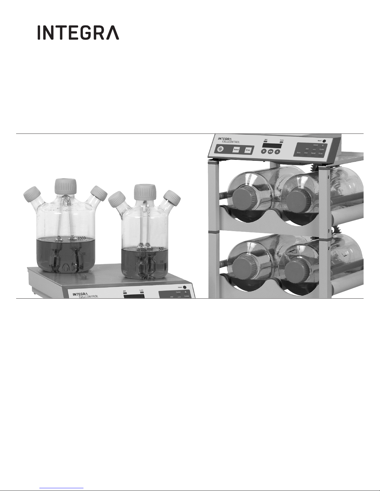
CELLROLL and CELLSPIN
Operating instructions
183411_V12
Page 2
2
Declaration of Conformity | Konformitätserklärung | Déclaration de conformité
INTEGRA Biosciences AG – 7205 Zizers, Switzerland
declares on its own responsibility that the products |
erklärt in alleiniger Verantwortung, dass die Produkte |
déclare sous sa responsabilité exclusive, que les produits
in accordance with the EC directives | gemäß der EU-Richtlinien |
sont conforme au terme de la directives CE
are in compliance with the following standards or normative documents: |
mit den folgenden normativen Dokumenten übereinstimmen: |
aux documents normatifs ci-après :
Standards for Canada and USA
Zizers, December 9th 2013
ledom ,epyTnoitpircseD
500681 ,100681LLORLLEC
100381NIPSLLEC
2006/95/EC Low voltage equipment
2004/108/EC Electromagnetic compatibility
2011/65/EC Restriction of Hazardous Substances
2002/96/EC Waste Electrical and Electronic Equipment
EN 61010-1 Safety requirements for electrical equipment
for measurement, control and laboratory use,
Part 1: General requirements.
EN 61326-1 Electrical equipment for measurement, control
and laboratory use - EMC requirements.
CAN/CSA-C22.2 No. 61010-1 Safety requirements for electrical equipment
for measurement, control and laboratory use,
Part 1: General requirements.
UL Std. No. 61010-1 Safety requirements for electrical equipment
for measurement, control and laboratory use,
Part 1: General requirements.
FCC, Part 15, Class A Emission
Elmar Morscher
CEO
Thomas Neher
Quality Manager
Page 3

2.1 Technical data . . . . . . . . . . . . . . . . . . . . . . . . . . . . . . . . . . . . . . 8
Contents
1. Safety precautions
2. Technical data
4. Assembly and installation CELLROLL/CELLSPIN
3. Abridged operating instructions CELLROLL/CELLSPIN
3.1 Instrument parameters . . . . . . . . . . . . . . . . . . . . . . . . . . . . . . . 9
3.2 Description of keys and functions . . . . . . . . . . . . . . . . . . . . . 10
3.3 Abridged instructions CELLROLL . . . . . . . . . . . . . . . . . . . . . 11
3.4 Abridged instructions CELLSPIN . . . . . . . . . . . . . . . . . . . . . . 13
4.1 Equipment provided - CELLROLL . . . . . . . . . . . . . . . . . . . . . 15
4.2 Equipment provided - CELLSPIN . . . . . . . . . . . . . . . . . . . . . . 16
4.3 Control unit CELLROLL/CELLSPIN . . . . . . . . . . . . . . . . . . . . 16
4.4 Designation of individual instrument parts . . . . . . . . . . . . . . 17
4.5 Vertical assembly - CELLROLL . . . . . . . . . . . . . . . . . . . . . . . 18
4.6 Horizontal assembly - CELLROLL . . . . . . . . . . . . . . . . . . . . . 19
4.7 Disassembly - CELLROLL . . . . . . . . . . . . . . . . . . . . . . . . . . . . 20
4.8 Stirring unit - CELLSPIN . . . . . . . . . . . . . . . . . . . . . . . . . . . . . 21
4.9 Connecting the printer . . . . . . . . . . . . . . . . . . . . . . . . . . . . . . 22
4.10 Equipment disposal . . . . . . . . . . . . . . . . . . . . . . . . . . . . . . . . . 22
General precautions . . . . . . . . . . . . . . . . . . . . . . . . . . . . . . . . . . . . . . . . . . . . . 5
Installation of CELLROLL/CELLSPIN: location and conditions . . . . . . . . . . . . 5
Transport . . . . . . . . . . . . . . . . . . . . . . . . . . . . . . . . . . . . . . . . . . . . . . . . . . . . . . 5
Conditions of use . . . . . . . . . . . . . . . . . . . . . . . . . . . . . . . . . . . . . . . . . . . . . . . 6
Dangers involved when safety precautions are not observed . . . . . . . . . . . . . 6
Safety at work . . . . . . . . . . . . . . . . . . . . . . . . . . . . . . . . . . . . . . . . . . . . . . . . . . 6
Qualification of operating personnel . . . . . . . . . . . . . . . . . . . . . . . . . . . . . . . . . 6
Safety aspects for user company . . . . . . . . . . . . . . . . . . . . . . . . . . . . . . . . . . . 6
Changes in configuration/design by user . . . . . . . . . . . . . . . . . . . . . . . . . . . . . 6
Power requirements . . . . . . . . . . . . . . . . . . . . . . . . . . . . . . . . . . . . . . . . . . . . . 7
3
Page 4

4
5.1 Operating steps
Starting and stopping the system . . . . . . . . . . . . . . . . . . . . . . . . . . . . . . . . . . . 23
Switching on and off . . . . . . . . . . . . . . . . . . . . . . . . . . . . . . . . . . . . . . . . . . . . . 23
Selecting outputs (OUTPUT 1/OUTPUT 2) . . . . . . . . . . . . . . . . . . . . . . . . . . . 23
Configuration of connected instruments . . . . . . . . . . . . . . . . . . . . . . . . . . . . . . 24
5.2 CELLSPIN - specific CELLSPIN functions
Stirring - "SPEED" . . . . . . . . . . . . . . . . . . . . . . . . . . . . . . . . . . . . . . . . . . . . . . 24
Pendular stirring angle . . . . . . . . . . . . . . . . . . . . . . . . . . . . . . . . . . . . . . . . . . . 25
Interval mode "––" . . . . . . . . . . . . . . . . . . . . . . . . . . . . . . . . . . . . . . . . . . . . . . . 26
5.3 CELLROLL - specific CELLROLL functions
Rolling speed - "SPEED" . . . . . . . . . . . . . . . . . . . . . . . . . . . . . . . . . . . . . . . . . 26
Rocking angle . . . . . . . . . . . . . . . . . . . . . . . . . . . . . . . . . . . . . . . . . . . . . . . . . 27
5.4 CELLROLL/CELLSPIN - common functions
Running time mode "" . . . . . . . . . . . . . . . . . . . . . . . . . . . . . . . . . . . . . . . . . .28
Cycle mode "CYCLES" . . . . . . . . . . . . . . . . . . . . . . . . . . . . . . . . . . . . . . . . . . . 29
Printout and overview of program parameters "PRINT . . . . . . . . . . . . . . . . . . . 30
Storing programs "STORE" . . . . . . . . . . . . . . . . . . . . . . . . . . . . . . . . . . . . . . . 32
Recalling and viewing programs "RECALL" . . . . . . . . . . . . . . . . . . . . . . . . . . . 32
6. Troubleshooting
7. Guarantee/Cleaning
5. Detailed operating instructions
8. Manufacturer and Service Contacts
Page 5
5
General
Throughout the manual, the following symbols will be used to indicate general precautionary measures:
Indication: information on the correct use of
CELLROLL/CELLSPIN.
Warning: Warning that, if safety precautions are not
observed, damage may result to the instruments.
Please read all documentation.
Danger: Warning that, if safety precautions are not
observed, injury to personnel may result.
Installation: Location and conditions
CELLROLL/CELLSPIN are intended for use in a laboratory.
Ambient conditions for the devices CELLROLL/
CELLSPIN see chapter Technical data
Warning: Always locate the control unit outside of an incubator if used.
Avoid exposing the control unit and power supply to direct
sunlight or high humidity.
Locate CELLROLL in such a way that personnel
cannot come in contact with the cogs.
Transport
Always grip CELLROLL on the base when transporting
1. Safety precautions
Page 6

6
Conditions of use
CELLROLL is a modular and expandable roller system for cell cul-
tivation and preparation of cell products in roller bottles. It is suitable for use with adherent cells and cell suspensions. The instrument is not designed for any other applications and should therefore not be used for such.
CELLSPIN is a spinning system comprising four stirring units for
the gentle cultivation of cells and the preparation of cell products in
spinning vessels. It is suitable for use with cell suspensions and immobilised adherent cells (e.g. microcarriers/alginate inclusion). The instrument is not designed for any other applications and should therefore not be used for such.
Dangers involved when safety precautions are not
observed
CELLROLL/CELLSPIN are state-of-the-art instruments with respect
to current technology and are safe to use. Some danger may exist
if the instruments are used by untrained personnel. Any person given
the task of operating CELLROLL/CELLSPIN must first read the operating and safety instructions and understand them fully or be thoroughly trained by a superior in the use of the instruments before
operating the instrument.
Safety at work
Independent of any safety precautions listed here, all other relevant
safety aspects - e.g. GLP, GMP, professional trade associations,
Department of Health, trade supervisory authorities - must be
observed.
Qualification of operating personnel
Normally, a technical qualification is required. Specialist knowledge
is required when using CELLROLL/CELLSPIN if all danger is to be
avoided.
Personnel without formal technical qualifications do not as a rule
possess such specialised information and should therefore only be
allowed to operate CELLROLL/CELLSPIN if properly trained and
under the supervision of suitably qualified personnel.
Safety aspects for the user company
The supervisors of operating personnel must have read and understood all the safety precautions involved and must ensure that these
are adhered to. They must also ensure that operating personnel also
understand and observe all safety rules.
Prior to operating CELLROLL/CELLSPIN, the supervisor must ensure
that no other dangers exist, especially if other instruments and systems are also being used.
If necessary, additional safety instructions must be compiled by the
supervisor. The user company must, if necessary, in order to exclude
all possible danger, compile explicit safety instructions and have these
signed by the staff responsible. In addition, clear competences must
be established as to who is responsible for the operation of CELLROLL/CELLSPIN so that these potential dangers can be reduced
to an absolute minimum.
Page 7
7
Changes in configuration/design by user
No changes may be made to CELLROLL/CELLSPIN. Any parts that
become defective must be replaced by original INTEGRA Biosciences
parts.
CELLROLL/CELLSPIN may not be altered in design or in any of their
safety aspects without the express written permission of INTEGRA
Biosciences. In particular, no alterations may be made to any of the
protective functions. Any alteration made releases INTEGRA
Biosciences from any liability for damage caused.
Power requirements
Checking the power supply
Check the power supply at the location and ensure that it complies
with that of the instrument.
Indication: Using the wrong power supply may damage
electronic components in the instrument.
Connecting to the power supply
Connect CELLROLL/CELLSPIN to the power supply using the cable
provid ed.
Danger: The instrument may not be used if insufficient
protection is provided as this may expose personnel
to the danger of electrical current injury.
NB: When connecting or disconnecting the instrument
from the control unit the latter must always first be
switched off otherwise the electronics may be damaged or a program interrupted.
Page 8

8
2. Technical data
CELLROLL
Width Depth Height
1 Deck 295 mm 360 mm 240 mm
2 Decks 295 mm 360 mm 400 mm
3 Decks 295 mm 360 mm 560 mm
4 Decks 295 mm 360 mm 720 mm
Control unit: 295 mm 80 mm 60 mm
Speed: "Motor unit": 0.1 – 2.0 rpm
"Motor unit fast": 2.0 – 6.0 rpm
Power Supply:
Input: 100 – 240 VAC/47 – 63 Hz/1.6 A
Output: 9.5 VDC/4.0 A/38 W
Weight:
Motor unit: 1.85 kg
Deck: 1.7 kg
Operating Condition:
Operation
Motor-unit/ Deck: 5 – 40 °C/max. 99% RH/max. 10% CO
2
Operation Control unit: 5 – 40 °C/max. 80% RH
Storage: -10 – 50 °C/max. 95% RH
Degree of protection:
Motor-unit/Deck: IP54
Control unit: IP21
2.1 Technical data
CELLSPIN
Width Depth Height
Drive: 295 mm 330 mm 60 mm
Control unit: 295 mm 80 mm 60 mm
Speed: 5 – 75 rpm
Power Supply:
Input: 100 – 240 VAC/47 – 63 Hz/1.6 A
Output: 9.5 VDC/4.0 A/38 W
Weight:
Control unit: 0.5 kg
Stirrer unit: 2.9 kg
Operating Condition:
Operation Stirrer unit: 5 – 40 °C/max. 99% RH/max. 10% CO
2
Operation Control unit: 5 – 40 °C/max. 80% RH
Storage: -10 – 50 °C/max. 95% RH
Degree of protection:
Stirrer unit: IP54
Control unit: IP21
Page 9
9
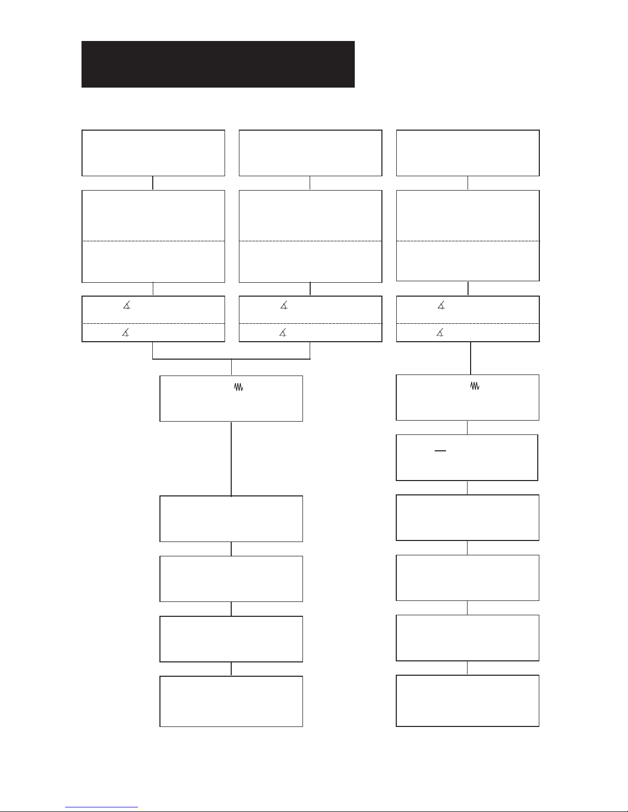
3.1 Instrument parameters
3. Abridged operating instructions
CELLROLL /CELLSPIN
Storing of programs – "STORE"
Memories Pr. 01 – Pr. 10
Recalling programs – "RECALL"
Pr. 01 – Pr. 10
CELLROLL
Motor unit fast (2 – 6 rpm)
"SPEED" for continuous rolling
(rolling with no directional change)
2.0 – 6.0 in steps of 0.25
and for rocking
(rolling with directional change)
ANGLE " " for rocking
(180° – 1440° in steps of 180°)
ANGLE ""for rolling = 0°
CELLSPIN
"SPEED" for continuous stirring
(= continuous stirring)
5.0 – 40.0 rpm in steps of 2.5
40.0 – 75.0 rpm in steps of 5.0
"SPEED" for pendular stirring
(= stirring with directional change)
5.0 – 40.0 rpm in steps of 2.5
ANGLE " " for pendular stirring
(180° – 1440° in steps of 180°)
ANGLE ""continuous stirring = 0°
RUNNING TIME ""
(00.05 h.min. - 99.59 h.min.) or
unlimited = Con
Cycles – "CYCLES"
for programming
1 – 9999
CELLROLL
Motor unit (0.1 – 2 rpm)
"SPEED" for continuous rolling
(rolling with no directional change)
0.1 – 1.0 in steps of 0.1
1.0 – 2.0 in steps of 0.5
and for rocking
(rolling with directional change)
ANGLE " " for rocking
(180° – 1440° in steps of 180°)
ANGLE ""for rolling = 0°
Print-out of protocols – "PRINT"
For viewing stored programs P1
Protocol print-out P2
Print-out of stored programs P3
Storing of programs – "STORE"
Memories Pr. 01 – Pr. 10
Recalling programs – "RECALL"
Pr. 01 – Pr. 10
RUNNING TIME ""
(00.05 h.min. - 99.59 h.min.) or
unlimited = Con
PAUSE " "
(00.00 h.min. - 99.59 h.min.)
Cycles – "CYCLES"
for programming
1 – 9999
Print-out of protocols – "PRINT"
For viewing stored programs P1
Protocol print-out P2
Print-out of stored programs P3
Page 10
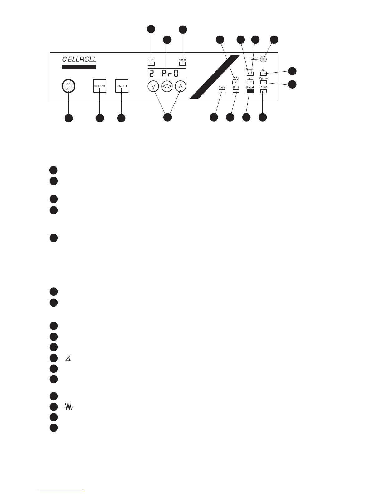
3.2 Brief description of keys and functions
Keys:
ON/OFF: Switches the instrument on/off
SELECT: Switches between parameters. The corresponding green LED will light and the most
recently set value will appear in the display.
ENTER: For confirming the value entered.
∨/∧: Keys "∨" and "∧" alter the corresponding parameters stepwise, the values being shown on
the display.
By keeping keys "∨" and "∧" pressed, all parameter values are displayed in rapid sequence.
< >: For:
a) Changing e.g. from hours to minutes and vice versa when setting time.
b) Switching between OUTPUT 1 and OUTPUT 2 in the functions "SPEED" and "RECALL".
c) Activating/deactivating the print options P2 and P3 in the function "PRINT".
Function LED’s :
STORE: Storing of programs
PRINT: P1: Display of stored programs
P2: Setting the printing interval
P3: Print out of stored programs
RECALL: Recalling stored programs
PUMP: Additional function
CYCLES: Number of times a program should be repeated
: Angle for pendular/circular stirring and rocking/rolling
ALARM: Red lamp lights if there is malfunction
SPEED: Speeds for pendular/circular stirring and rocking/rolling and for selecting between
OUTPUT 1 and OUTPUT 2
–––– : Pause between two programmed runs
: Running time (specific/continuous) for pendular or continuous stirring, rocking or rolling
h/min: Activated during entry of time parameter
rpm: Activated during entry of speed
2
4
3
4
1
17
12
5
16
11
6
13
7
15
8
14
9
17
16
10
10
11
7
1213
6
8
14
9
10
2
3
5
15
1
Page 11

NB: The control unit must always be located outside the incubator!
– Connect C ELLRO LL t o the control u nit with the cable
provided.
If connection has not been made, "Err 02" will appear on the
dis play on starting the instrument. Check the connection and
cancel the error message by pressing "ENTER".
– In the event of a power failure, any unstored data of both out-
puts will be automatically stored and recalled once the power has
been restored. The "Err 03" in the display can be cancelled by
pressing "ENTER".
Entering the program for working with CELLROLL
☞ Switch on the instrument by pressing the ON/OFF key. The
green LED under "RECALL" will light.
☞ Press "SELECT" and select the function "SPEED".
In the function "SPEED":
Selecting the output:
☞ Select OUTPUT 1 or OUTPUT 2 via key "< >".
Setting the rolling speed:
CELLROLL is equipped with two different motors. The control unit
will always select the right one.
"CELLROLL" Motor unit (0.1-2.0 rpm):
☞ Set the speed within the range 0.1 - 2.0 rpm via "∨" and "∧".
Confirm by pressing "ENTER".
"CELLROLL" Motor unit fast (2.0-6.0 rpm):
☞ Set the speed within the range 2.0 - 6.0 rpm via "∨" and "∧".
Confirm by pressing "ENTER".
In the function " ":
Selecting the pendular angle:
☞ For continuous rolling (no directional change), set the
pendulum angle to "0°" via "∨". Confirm by pressing "ENTER".
☞ For rocking (with directional change), set the pendulum angle
within the range 180° - 1440° (= 0.5 - 4.0 bottle revolutions).
Confirm by pressing "ENTER".
NB: If "rocking" has been selected, please observe the restrictions
impos ed below under " " and "–".
In the function "":
Set the rolling duration:
The duration of continuous rolling or rocking can be set to:
- A limited time between 00.05 (h/min) - 99.59 (h/min), or
- An unlimited time as "Con".
☞ To select a specific rolling duration
, set hours and/or minutes
via the "< >" key and alter via "∨" and "∧". Confirm by pressing
"ENTER".
☞ To select continuous rolling or rocking operation, activate the
h/min function and press the "∨" key until the display shows
less than 0.05 and "Con" appears. Confirm by pressing
"ENTER".
11
3.3 Abridged operating instructions - CELLROLL
Page 12

In the function " – ":
The pause interval cannot be selected for either motor unit and is
overrun.
In the function "CYCLES":
Repeating programs:
Programs can be set to repeat within the range 1 - 9999.
☞ Select the required value via "∨" and "∧". Confirm by pressing
"ENTER".
NB: If in the function " " continuous stirring has been selected,
"Con" will appear automatically under "CYCLES".
In the function "STORE":
Storing programs:
Up to 10 programs can be stored in separate memories.
☞ Select a memory between Pr. 01 and Pr. 10 via keys "∨" and
"∧". Confirm by pressing "ENTER".
In the function "RECALL":
Recalling stored programs:
☞ Select a memory between Pr. 01 and Pr. 10 via keys "∨" and
"∧". Confirm by pressing "ENTER". Three beeps will be given
and the program will start.
NB: When recalling a program, please remember to take the output into account.
Selecting the output:
☞ Key "< >" can be used to select OUTPUT 1 or 2.
Additional functions: "PRINT" and "PUMP":
Information on the operating steps for these functions along with the
options
P1 = view stored programs
P2 = entering print interval
P3 = Print-out of stored programs
is given in the detailed operating instructions.
12
Page 13

NB: The control unit must always be located outside the incubator!
– Connect CELLSPIN to the control unit with the cable provided.
If connection has not been made, "Err 02" will appear on the
display on starting the instrument. Check the connection and
cancel the error message by pressing "ENTER".
– In the event of a power failure, any unstored data of both out-
puts will be automatically stored and recalled once the power has
been restored. The "Err 03" in the display can be cancelled by
pressing "ENTER".
Entering the program for working with CELLSPIN:
☞ Switch on the instrument by pressing the "ON/OFF" key. The
green LED under "RECALL" will light.
☞ Select the function "SPEED" by pressing "SELECT".
In the function "SPEED":
Selecting the required output:
☞ Select OUTPUT 1 or OUTPUT 2 via key "< >".
Selecting the stirring speed:
NB: In the "SPEED" mode, the rpm limit for pendular stirring must
be taken into account so that the pendulum angle " " can be
set.
☞ For continuous stirring (no directional change), set the
speed within the range 5 - 75 rpm and for pendular stirring
(stirring with directional change) within 5 - 40 rpm via "∨" and
"∧". Confirm by pressing "ENTER".
In the function " ":
NB: The function " " can only be selected when the set speed is
<
40 rpm. If a value > 40 rpm has been selected, the " " function
will be overrun and the angle automatically set to "0".
Selecting the pendular angle:
☞ For continuous stirring, set the pendulum angle to "0°" via "∨".
Confirm by pressing "ENTER".
☞ For pendular stirring, set the pendulum angle via keys "∨"
and "∧" within the range 180° - 1440°. Confirm by pressing
"ENTER".
In the function " ":
Setting the stirring duration:
The duration of stirring can be set to:
- A limited time between 00.05 (h/min) - 99.59 (h/min), or
- An unlimited time as "Con".
☞ To select a specific stirring duration
, set hours and/or minutes
via the "< >" key and alter via "∨" and "∧". Confirm by pressing
"ENTER".
☞ To select continuous stirring, activate the h/min function with
the "< >" key and press the "∨" key until the display shows
less than 0.05 and "Con" appears. Confirm by pressing
"ENTER".
13
3.4 Abridged operating instructions - CELLSPIN
Page 14

In the function " – ":
Setting the interval:
Within any program, an interval can be freely selected within the range
00.00 (h/min) - 99.59 (h/min).
☞ Choose the position for hours and minutes via key "< >" and
set the interval via keys "∨" and "∧". Confirm by pressing
"ENTER".
In the function "CYCLES":
Repeating programs:
Programs can be set to repeat within the range 1 - 9999.
☞ Select the required value via "∨" and "∧". Confirm by pressing
"ENTER".
NB: If in the function " " continuous stirring has been selected,
"Con" will appear automatically under "CYCLES".
In the function "STORE":
Storing programs:
Up to 10 programs can be stored in separate memories.
☞ Select a memory between Pr. 01 and Pr. 10 via keys "∨" and
"∧". Confirm by pressing "ENTER".
In the function "RECALL":
Recalling stored programs:
☞ Select a memory between Pr. 01 and Pr. 10 via keys "∨" and
"∧". Confirm by pressing "ENTER". Three beeps will be given
and the program will start.
NB: When recalling a program, please remember to take the output into account.
Selecting the output:
☞ OUTPUT 1 or OUTPUT 2 can be selected via key "< >".
Additional functions: "PRINT" and "PUMP":
Information on the operating steps for these functions along with the
options
P1 = view stored programs
P2 = entering print interval
P3 = Print-out of stored programs
is given in the detailed operating instructions.
14
Page 15

Accessories:
Part No.
Deck for system extension (2 roller bottles per deck) 186 026
Storage deck for horizontal extension, with drive belt, 186 030
spacers and deck cover (Deck 186 026 not included)
Control cable for 2nd output, length 2 m 186 050
Interface cable for connection to printer or PC 186 041
Drive unit standard (0.1 - 2.0 rpm), incl. control cable 186 015
Drive unit fast (2.0 - 6.0 rpm), incl. control cable 186 020
Control unit incl. mains adapter 186 013
Mains adapter 186 238
4.1 Equipment provided - CELLROLL
4. Assembly and installation
CELLROLL/CELLSPIN
CELLROLL (Part. No. 186 001) or
CELLROLL fast (Part. No. 186 005) comprises:
1 Control unit
1 "Drive unit", 0.1-2.0 rpm (for 186 001)
or
1 "Drive unit fast ", 2.0-6.0 rpm (for 186 005)
2 Decks for 4 roller bottles
(incl. connectors for assembly)
1 Power cable
1 Mains adapter
1 Control cable, length 2 m
1 Operating instructions
15
Page 16

4.3 Control unit for CELLROLL/CELLSPIN
The CELLROLL/CELLSPIN control unit includes:
① Connection for power cable and integrated interface
RS 232 C for connecting a printer/PC (activated via Y-cable)
to POWER IN.
Two asynchronous outputs - OUTPUT 1 and OUTPUT 2
for connecting: – 1 CELLSPIN and 1 CELLROLL
– or 2 CELLSPINS or 2 CELLROLLS
4.2 Equipment provided - CELLSPIN
①
Accessories: Article No.
Control cable for 2nd output, length 2 m 186 050
Control unit incl. mains adapter 183 013
Interface cable for connection to printer or PC 186 041
Stirring platform 183 015
Mains adapter 186 238
Conversion kit for using CELLSPIN 183 260
with impeller-type flasks
Spinner flasks (www.integra-biosciences.com)
CELLSPIN (Part No. 183 001) comprises:
1 Stirring platform incl. control cable
1 Control unit incl. mains adapter
1 Power cable
1 Mains adapter
1 Control cable, length 2 m
1 Operating instructions
9,
5
V
,
3
A
9,5 V ,3 A
16
Page 17

4.4 Designation of individual instrument parts
CELLROLL - Motor unit
① Socket
➁ Deck
CELLSPIN -stirring unit with 4 stirrers
③ Left cable channel
④ Socket
⑤ Right cable channel
Control cable
⑥ Socket
⑦ Plug
Mains cable
⑧ Socket
⑥⑦
⑧
17
Page 18

4.5 Vertical assembly - CELLROLL
☞ Insert 4 connectors and 4 end pieces each into the bottom and
the top of the first deck until they audibly fit into position.
Via further connectors, up to four decks may be connected vertically. The top deck of a tower remains without connectors.
The gears of the decks mesh together automatically. Locate
CELLROLL in such a way that personnel do not come in contact
with the cogs.
NB: Never stack more than 4 decks at any one time.
NB: When transporting CELLROLL, always grip the lower
deck.
☞ Place the CELLROLL motor unit with its ex-factory fitted con-
nectors on the last free deck and ensure that it engages in position.
If running special applications in which the usual cell culture conditions (temperature, humidity etc.) are not necessary, the control
unit can be fitted directly to the guide slot on the motor unit.
NB: Before locating CELLROLL/CELLSPIN, please read
and observe the safety conditions listed in section 1.
☞ Connect the plug of the low voltage cable ① to "POWER IN"
at the rear of the control unit and tighten.
☞ Place the power cable in the cable clips located at the side of
the shelf of the motor unit. If necessary, mount additional clips
at the rear of the tower. Insert cable.
Take care that the cable does not come into contact with
the cogs.
☞ Connect the power supply to power.
NB: Always locate the control unit outside of the incubator.
18
Page 19

4.6 Horizontal assembly - CELLROLL
☞ Place two modules furnished with end pieces/intermediaries
next to each other.
☞ Snap two double-clips onto the round stud of the right module.
☞ Place synchronous belt on both crown gears.
☞ Snap the mounted double-clips onto the round stud of the left
modu-le.
Now the synchronous belt is stretched.
Up to three additional decks may be added vertically if they are
connected with intermediaries.
The individual module's composition gears mesh together automatically.
The top deck or each tower remains without intermediaries.
Continue assembly following the instructions.
☞ Place the CELLROLL motor unit with its ex-factory fitted con-
nectors on the top deck of one of the towers and ensure that
it engages in position.
☞ Connect the control cable to the flange socket of the motor unit
and to OUTPUT 2 of the electronics unit.
NB: Never stack more than 4 decks at any one time.
NB: When transporting CELLROLL, always grip the lower
deck.
19
Page 20

☞ Connect the low voltage cable plug ① to "POWER IN" at the
rear of the instrument and tighten.
☞ Insert the low voltage cable in the side clips of the motor unit.
NB: Ensure that the cable does not come into contact
with the cogs.
☞ Add more cable clips on the back of one of the towers as it
appears appropriate and use them to guide mains cable.
☞ Mount stacker plate onto the second tower with intermediaries.
☞ Connect the power pack to the source of electricity.
NB: Always locate the control unit outside of the incubator.
4.7 Disassembly - CELLROLL
☞ Disconnect the power cable.
☞ Remove the low voltage cable from the clips.
☞ Disconnect the plug of the low voltage cable from control unit.
☞ Press the green knobs on the framework and disconnect the
decks.
☞ Disassemble motor unit and decks.
20
Page 21

4.8 Putting a CELLSPIN stirring unit into
operation
☞ Insert the low voltage cable into the right hand duct on the base
of the stirring unit housing.
☞ Connect the low voltage cable to "POWER IN" at the rear of
the control unit and tighten.
☞ Connect control cable to OUTPUT 1/2 of the control unit to the
flange socket of the stirring unit.
If running special applications in which the usual cell culture conditions (temperature, humidity etc.) are not necessary, the control
unit can be fitted directly to the guide slot on the motor unit. Ensure
that it engages.
NB: In setting up CELLROLL/CELLSPIN, please observe
the conditions for location and setting up as outlined in
section 1.
☞ Connect power supply to source of electricity.
NB: Always locate the control unit outside of the incubator.
If two stirring units are used, these should be connected via two
control cables to OUTPUTS 1/2 of the electronics unit.
21
Page 22

4.9 Connection to a printer or PC
☞ Connect the female, 4-pin socket ➊ of the Y-cable (186.041) to
the power input of the control unit.
☞ Connect the male, 4-pin plug ➋ of the Y-cable to the power
supply.
Printer with serial interface
☞ Connect the Sub-D9 plug ➌ to the serial interface of the printer.
Printer with parallel interface
☞ Connect the Sub-D9 plug ➌ to the printer using the delivered
female-female adapter (gender changer) ➍ and a serial-parallel converter.
PC with hyperterminal software
☞ Connect the Sub-D9 plug ➌ to the serial port of the PC using
the delivered female-female adapter (gender changer) ➍ and the
delivered Null Modem adapter ➎.
RS 232 parameters setting for the printer/hyperterminal software
Baud rate: 2400
Parity: none
Data bits: 8
Start bit: 1
Stop bit: 1
4.10 Equipment disposal
The CELLROLL and CELLSPIN motor units and
the control unit are labelled with the "crossed-out
wheeled bin" symbol to indicate that this equipment
must not be disposed of with unsorted municipal
waste. Instead, it is your responsibility to correctly dispose of your waste equipment by handing it
over to an authorised facility for separate collection and recycling. It is also your responsibility to
decontaminate the equipment in case of biological,
chemical, and/or radiological contamination so as to protect from
health hazards the persons involved in the disposal and recycling
of equipment.
For more information about where you can drop off your waste equipment for recycling, please contact your local dealer from whom you
originally purchased the product or your local council.
By doing so, you will help conserve natural resources and you will
ensure that your waste equipment is recycled in a manner that protects human health and the environment. Thank you!
22
Page 23

Please read and observe the safety precautions
listed on page 5.
1. If, during entry of a new program or alteration of
individual parameters a pause >120 sec arises, the
current speed will appear in the display.
2. Alterations in the functions are indicated by the display blinking. The new entry is confirmed by pressing
the ENTER key resulting in the display stopping to
blink.
5.1 Operating steps
Starting and stopping the system
Switching on the instrument:
☞ Press the "ON/OFF" key. All LEDs will blink and the display will
briefly show 8.8.8.8.8.8. The green light under "RECALL" will
light. The last selected output (OUTPUT 1 or OUTPUT 2) will
appear at the left-hand side of the display. The last activated
program number will appear, blinking, at the right-hand side of
the display.
Switching off the instrument:
☞ Press the "ON/OFF" key; the instrument is switched off after
about 5 sec. which is indicated by the appearance of a red point
in the display.
Selection of OUTPUT 1 or OUTPUT 2
These outputs can be selected in the function "SPEED".
If only one instrument has been connected, the control unit will automatically select the correct output.
If two instruments are connected:
☞ Press the "SELECT" key until the green light under "SPEED"
and "rpm" lights.
The selected OUTPUT will appear at the left-hand side of the display whilst the current set stirring speed will appear at the righthand side.
☞ By pressing key "< >" either OUTPUT 1 or OUTPUT 2 can be
se lected.
5. Detailed Operating Instructions
23
Page 24

24
5.2 CELLSPIN –
Instrument-specific functions
Stirring speed - "SPEED"
In the function "SPEED", the speed for
circulatory stirring = continuous stirring
or for pendular stirring = stirring with directional change
can be set according to the following table:
Circulatory „SPEED“ rpm Angle
stirring
5 – 40 rpm in steps of 2.5 0°
40.0 – 75 rpm in steps of 5.0 0°
Pendular „SPEED“ rpm Angle
stirring
5.0 - 40.0 rpm in steps of 2.5 180°– 1440°
N.B.: The function "angle" can only be activated if a speed
of 40 rpm or less has been selected. If an entry of > 40
rpm is made, the angle function can not be used and will
be overrun automatically.
Setting the pendular and stirring speeds:
☞ Press the "SELECT" key until the green light under "SPEED" and
"rpm" lights. The currently set speed will appear in the display.
☞ Set the required speed using keys "∨" or "∧". The display will blink.
☞ Press the "ENTER" key to confirm entry.
Allocation of connected instruments
If CELLSPIN/CELLROLL is located in an incubator, the display of
the externally located control unit will indicate which instrument is
connected to which OUTPUT.
Procedure:
☞ Select the required OUTPUT 1 or OUTPUT 2 (in the func tion
"SPEED") by briefly pressing the "< >" key.
By continuously pressing key "< >", the instrument allocation will
appear in the display:
– CS for CELLSPIN
– Cr for CELLROLL with "motor unit" 0.1 to 2.0 rpm
– CrF for CELLROLL with "motor unit fast": 2.0 to 6.0 rpm
Page 25

25
Setting the angle for pendular stirring
In the function " " the angle for pendular stirring can
be set.
Pendular Angle „SPEED“ rpm
stirring
180°–1440° 5.0 – 40.0 rpm in steps of 2.5
*
If values > 40 rpm are entered, the angle " "will automaticallybe overrun.
Pendular stirring:
☞ Press the "SELECT" key until the green light under " " lights.
☞ Set the required value using keys "∨" or "∧".
☞ Press the "ENTER" key to confirm the values.
Circulatory stirring:
☞ Press the "SELECT" key until the green light under " " lights.
☞ Enter "0" using the "∨" key.
☞ Press the "ENTER" key. The value entered will be confirmed.
Page 26

26
5.3 CELLROLL –
Instrument-specific functions
The roller system CELLROLL is available with two types
of motor unit:
"Motor unit" (0.1 to 2.0 rpm)
"Motor unit fast" (2.0 to 6.0 rpm)
The control unit automatically recognises the type of motor unit
connected and indicates the appropriate ranges in the display.
Setting the speed for continuous rolling and
rocking - "SPEED":
In the function SPEED, the speeds for
continuous rolling = rolling without directional change
and rocking = rolling with directional change
can be set according to the following table:
Continuous "SPEED" rpm Bottles turns per Angle
rolling minute
"Motor unit" 0.1 - 2.0 rpm 0.1 – 2.0 0°
"Motor unit fast" 2.0 - 6.0 rpm 2.0 – 6.0 0°
Rocking "SPEED" rpm Bottles turns per
rocking cycle Angle
"Motor unit" 0.1 – 2.0 rpm 0.5 – 4.0 180° – 1440°
"Motor unit fast" 2.0 – 6.0 rpm 0.5 – 4.0 180° – 1440°
Interval mode "–––––"
In the function "––", the time interval between repetition of the program can be set.
For both motor units of CELLROLL the function pause
can not be selected and will be automatically overrun.
The interval between program runs can be set for CELLSPIN within the range 00.00 h.min to 99.59 h.min.
☞ Press the "SELECT" key until the green light under "––" and
"h.min" lights. The current setting will be shown in the display.
The "< >" key can be used to switch from hours to minutes. Set
the required values using keys "∨" or "∧".
☞ Press the "ENTER" key to confirm the settings.
For entry of functions running time, cycles, print, see following
pages.
Page 27

27
Setting the speed for continuous rolling and rocking:
☞ Press the "SELECT" key until the green light under "SPEED"
and "rpm" lights. The currently set and speed will appear in the
display.
☞ Set the required speed using the "∨" or "∧" keys. The display
will blink.
☞ Press the "ENTER" key to confirm. Function will be carried out.
Setting the angle for rocking
In the function " " the pendular angle rocking can be
set.
Continuous rolling: set the rocking angle to 0°.
Rocking:
☞ Press the "SELECT" key until the green light under " " lights.
☞ Set the required value using key "∨" or "∧".
☞ Press the "ENTER" key to confirm. Function will be carried out.
Continuous rolling:
☞ Press the "SELECT" key until the green light under " "lights.
☞ Set "0" using the "∨" key.
☞ Press the "ENTER" key to confirm the value. Function will be
carried out.
For setting running time, cycles, see following pages.
Page 28

28
Running time mode " "
The running time is the duration of stirring or rolling and can be
set from:
- 00.05 h.min to 99.59 h.min or
- unlimited = Con
In the mode " ", the key "< >" can be used to change between
hours and minutes.
Entry of a specified running time
Example: Running time of 12 hours 15 minutes:
☞ Press the "SELECT" key until the green light under " " and
"h.min." lights.
☞ Press the "< >" key. This activates the minute setting. Both right-
hand numerals will blink.
☞ Set a value of 15 using keys "∨" or "∧".
☞ Press key "< >". This activates the hour setting. Both left-hand
numerals will blink.
☞ Set the value of 12 using keys "∨" or "∧".
☞ Press the "ENTER" key. The running time starts immediately.
Entry of unlimited running time
☞ Press the select key until the green light under " " and under
"h.min." lights. The current value will appear in the display.
☞ Press the "< >" key to activate hours/minutes entry.
☞ Press the "∨" key until "Con" appears in the display below 0.05.
☞ Press the "ENTER" key. "Con" will appear in the display.
5.4 CELLROLL/CELLSPIN - common functions
Page 29

29
Cycle mode "CYCLES"
In the "CYCLES" mode, the number of cycles can be set from 1
to 9999. One cycle is the combination of the set running time and
the set interval (see CELLSPIN).
N.B.: If continuous running time has been entered, "Con" will appear in the display automatically in the mode CYCLES.
Setting the number of cycles:
☞ Press the "SELECT" key until the green light under "CYCLES"
lights.
☞ Set the required number of cycles using keys "∨" or "∧".
Page 30

30
PRINT - print-out and overview of program
parameters
Options of the function PRINT:
- Viewing stored programs - P1
- Print-out of protocols- P2
- Print-out of stored programs - P3
Selecting options:
☞ Press the "SELECT" key until the green light under "PRINT"
lights. "P1" will appear in the display.
Keys "∨" and "∧" can be used to switch between options P1, P2
and P3.
Confirm the selected option by pressing the "ENTER" key.
P1 - Viewing stored programs:
In this option, the individual parameters of a stored program can
be viewed.
☞ Select option P1 using key "∨ " or "∧" and confirm by pressing
the "ENTER" key.
☞ Enter the required program number between Pr. 01 and Pr. 10
using key "∨" or "∧".
☞ Press the "ENTER" key to confirm. The LED under "PRINT"
and "SPEED" will light. The speed of the selected program will
appear in the display.
The "SELECT" key can be used to call up the program parameters which than can be read off the display.
☞ Press the "SELECT" key until the green light under "PRINT"
lights again.
At this point, either further programs can be viewed or the
"PRINT" mode left.
a) To view further programs:
☞ Press the "ENTER" key. Select the required program number
between Pr. 01 and Pr. 10. Use the "SELECT" key to view the
required parameters.
b) To leave the "PRINT" mode:
☞ Press the "SELECT" key to move to the next required functions.
Page 31

31
P2 - Print-out of protocol
The print interval specifies the intervals at which the parameters
of an activated program are printed out.
☞ Select option P2 using keys "∨" or "∧" and confirm by pressing
"ENTER". The display for time entry will appear.
☞ Press the "< >" key to activate the hours/minutes entry. Set the
required printing interval using key "∨" or "∧" and confirm by
pressing "ENTER". "P2" will reappear in the display.
Briefly press key "< >" to activate print-out of the protocol. "≡ P2"
will appear at the right hand side of the display and the protocols
will be printed out at the required intervals.
Repressing key "< >" deactivates the protocol mode and "P2" will
reappear in the display.
N.B.: Any changes in parameter during the running of a program
are automatically and immediately noted on the print-out.
P3 - Print-out of stored programs:
In this option, all stored programs can be printed out. For each of
the system components, i.e.
• CELLSPIN
• CELLROLL "Motor unit"
• CELLROLL "Motor unit fast"
• External device
there are 10 memories available for each; these are noted on the
print-out.
N.B.: If two identical system components (e.g. 2 CELLROLLS, 2
CELLSPINS) have been connected, each will be allocated 5 memories.
☞ Select option P3 using key "∨" or "∧" and confirm by pressing
"ENTER".
The appropriate data will then be transmitted immediately to the
printer or PC connected.
Page 32

32
Storing programs - "STORE" mode
For each of the connected system components, 10 memories
(Pr. 01 to 10) are available for program storing.
N.B.: If two identical system components (e.g. two Cellrolls, two Cellspins) have been connected, each will be allocated 5 memories.
In addition, one further memory is provided with the following function: In the case of power failure, all data of the current program
for both outputs which have not been stored under "STORE" are
stored in this memory. Once power has returned, the programs automatically continue.
☞ Once all of the parameters have been entered, press the
"SELECT" key until the green light under "STORE" lights.
☞ Select a memory between 01 and 10 using key "∨" or "∧".
Confirm the number by pressing "ENTER".
N.B.: Should another parameter have been stored under this particular number, it will be overwritten by the new parameter entries.
Calling-up programs - RECALL mode
☞
Press the "SELECT" key until the green light under "RECALL"
lights.
☞ Set the required program number (Pr. 01 to Pr. 10) using keys
"∨" or "∧".
☞ Press the "ENTER" key. An acoustic signal will be given three
times in succession and the program will start.
After 120 sec., the current speed will appear in the display and
the instrument will move into function "SPEED".
Page 33

33
Problem Probable cause Remedial measure
CELLROLL or CELLSPIN control • Power interruption • Check all connections between control
unit doesn't switch on by unit, power supply and wall socket.
pressing the "ON/OFF" key
• Faulty power supply • Replace the power supply with a new one.
An error message appears:
- Err 02 • Electronic unit disconnected • Check the connection between control unit
and device. Make sure that the screw tops
are fastened when using a control cable.
If this measure is unsuccessful, replace the
control cable with a new one.
Press "ENTER" to quit Err 02.
- Err 03 • Power failure • A power interruption has appeared during a
program run.
Press "ENTER" to quit Err 03.
Printer doesn't work • Printer disconnected • Check power connection and connection
between control unit and printer. You have to
use a special Y-cable (art.-no.: 186 041)
• Incorrect settings • Make sure that a printer with a serial
interface is connected. Settings:
Baudrate: 2400
Parity: none
Databits: 8
Startbit: 1
If you like to use a printer with a parallel
interface you have to connect
a serial/parallel converter additionally
• No printing interval time • See manual
entered/printer mode
deactivated
Selected program doesn't run • Incorrect settings • Check all program settings, make sure
that the value of the entered speed is > "0".
Display shows indefinable • Line transient (e.g. by flash RESET the control unit:
characters of lightning) - Connect the control unit to power.
or • Data loss in random - Switch the unit off by pressing the
input data will not be accepted access memory "ON/OFF" key.
• Software crash - Press "∨" once until "––" appears while
switching on
Press "<>" twice
Press "∧" three times till the display
shows " _ _ _ _ _ _"
The "Reset" is finished automatically, the
display will show "LL" for 2 seconds.
Disconnect the control unit from power
supply for a few seconds afterwards,
then connect it again.
WARNING!
All stored programs are deleted after a
RESET!
6. Troubleshooting
Page 34

7. Guarantee/Cleaning
Guarantee
All instruments are guaranteed for 1 year.
Cleaning
Cleaning of the instruments
Always switch off the instrument and disconnect it from
the mains when carrying out maintenance/cleaning
work.
34
8. Manufacturer and Service Contacts
Manufacturer:
INTEGRA Biosciences AG
CH-7205 Zizers
Switzerland
www.integra-biosciences.com
info@integra-biosciences.com
Customer service:
Please contact your local INTEGRA Biosciences representive.
To find out name and address of your local representive go to
www.integra-biosciences.com.
Further information is available from info@integra-biosciences.com.
© 2015 INTEGRA Biosciences AG
All rights to this documentation are reserved. In particular the rights of reproduction, processing,
translation and the form of presentation lie with INTEGRA Biosciences AG. Neither the complete
documentation nor parts thereof may be reproduced in any way, or stored and processed using
electronic media or distributed in any other way without the written consent of INTEGRA Biosciences AG.
This operating instruction manual has the article number 183 411, version number V12.
To clean the instruments, use a cloth moistened with customary
cleansing agents like soapy water, a 70 % ethanol solution or
isopropanol. Do not spray directly on the instrument but use a cloth
and wipe dry directly after cleaning. Never use acetone!.
Page 35

03/2015 183411_V12_OI_CELLROLL_CELLSPIN
 Loading...