

Page 1
Installation and operation manual
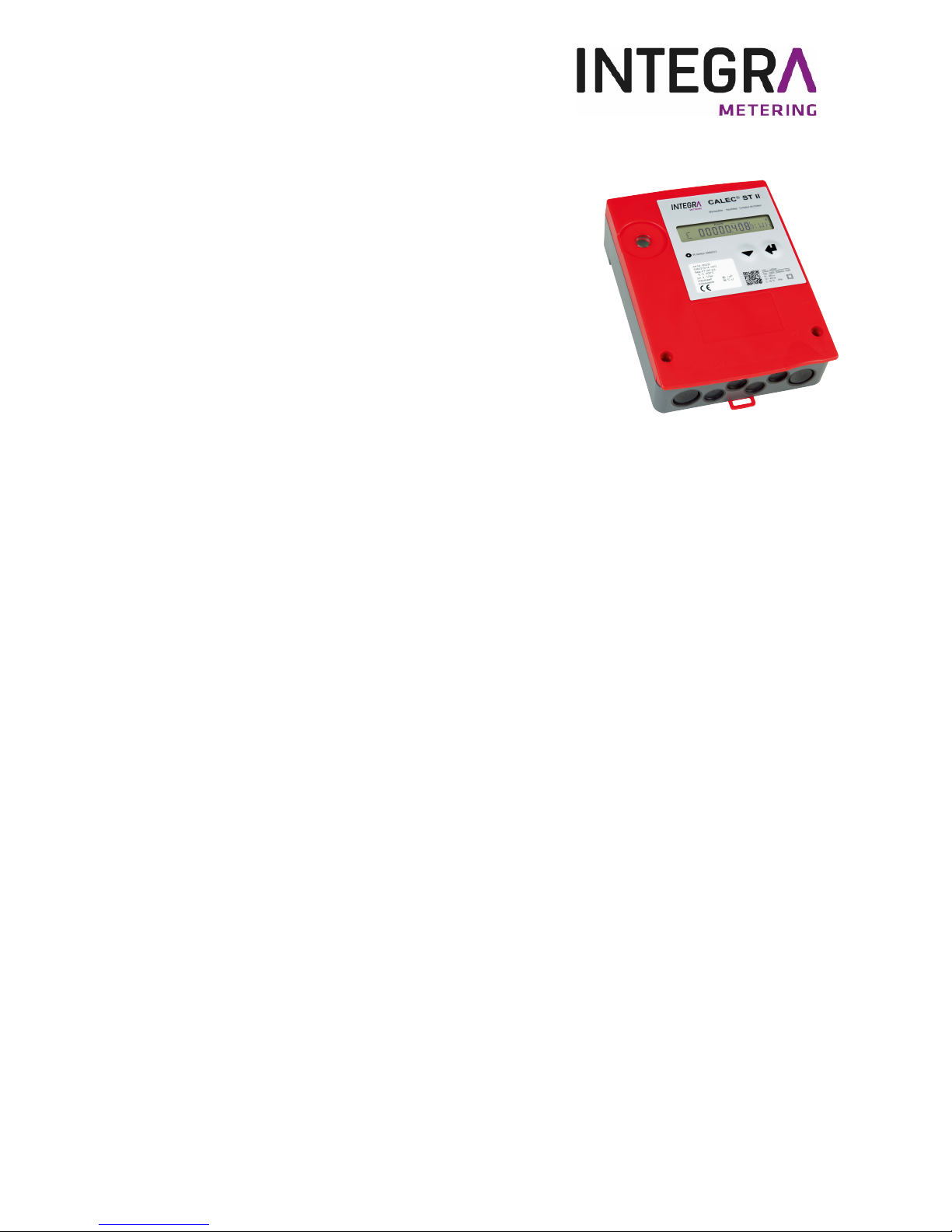
CALEC® ST II
Table of contents
1 Safety 2
2 Structure of a measuring point 4
3 Scope of delivery, installation accessories 5
4 Installation 6
5 Controls and operation 32
6 Maintenance and repair 49
7 Disposal 49
8 Technical specifications 50
9 CE Declaration of Conformity 54
10 Appendix 55
VD 3-126e 01.2018
Page 2
1 Safety
1.1 Intended use
CALEC® ST II is a high precision instrument designed for the collection, analysis, presentation and transmission
of information. Improper or non-intended use of the device may compromise operational safety. We accept no
liability for any resulting damages.
1.2 Notes on safety instructions and symbols
The device has been designed to fulfil modern safety requirements. It has been tested and delivered in a condition
that ensures safe operation. However, improper or non-intended use of the device may result in it becoming
dangerous. Please always pay attention to the safety instructions in this manual which are accompanied by the
following symbols:
2
CALEC® ST II
WARNING!
WARNING indicates an action or measure which, if performed incorrectly, can cause
potentially life-threatening injuries and lead to a high safety risk. Always follow the
instructions and proceed with caution.
NOTE!
NOTE indicates an action or measure which, if performed incorrectly, may have an
indirect effect on the operation of the device, or trigger an unexpected response.
COMMENT!
COMMENT provides information and recommendations for efficient and trouble-free
operation.
CAUTION!
CAUTION indicates an action or measure which, if performed incorrectly, can cause
minor injuries and/or incorrect operation or destruction of the device. Always follow the
instructions.
REFERENCE!
REFERENCE refers to additional documents.
Page 3
3
CALEC® ST II
1.3 Installation, startup and operation
General hazards and warnings
This device is intended for permanent installation with a fixed electrical connection. The installation, connection
to the electricity supply, startup and maintenance must be carried out by trained, qualified personnel who are
authorised to perform this type of work. The respective specialist personnel must have read and understood this
installation and operation manual, and follow the instructions contained therein. The operator must ensure that
the measuring system is wired correctly in accordance with the wiring diagrams. Contact protection is deactivated
when the cover is removed (risk of electric shock). The housing may only be opened by qualified personnel.
Disconnect the power supply prior to electrical installation, and ensure that it cannot be reconnected
without your consent.
Pay attention to the following points during installation:
• Voltage, operating data
• Maximum transmission length
• Cable cross-section and length
• Ambient temperature and installation position
1.4 Technical progress
We reserve the right to modify the technical specifications without prior notice.
WARNING!
Danger of electrocution!
Touching or gripping live electrical parts can cause an electric shock, which may
result in burns, paralysis or death.
• The device should only be opened, installed or repaired when the power has
been switched off.
• Only specialist technicians are authorised to work on or with mains voltage.
They must comply with the applicable regulations.
• Only the intended terminals should be used to connect the device to the mains
supply.
REFERENCE!
Latest version of this manual!
The latest version of this manual is available at:
http://www.aquametro.ch/qr/prod/calec-st/11111.html
Page 4
4
CALEC® ST II
2 Structure of a measuring point
A complete measuring point for thermal energy consists of the CALEC® ST II energy calculator, paired temperature
sensors and flow sensor.
The applicable regulations and recommendations for installation and operation must also be complied with,
e.g. Section 6 of EN 1434, and the recommendations of professional associations such as the „Merkblätter der
Fernwärmeversorgung“ [fact sheets for district heating] issued by the German Energy Efficiency Association for
District Heating, Cooling and CHP (AGFW). The installation of control immersion sleeves is mandatory in some
countries (e.g. in France after FDE 39-007).
NOTE!
Type of temperature sensor, pulse value, installation side!
Check whether the temperature sensor type (e.g. Pt100), pulse value and installation
side (cold, hot) of the flow sensor match the nameplate on the CALEC® ST II.
NOTE!
Calibrated device!
Depending on the version, the CALEC® ST II is a calibrated measuring device
(see calibration markings on the nameplate).
Calibration is rendered invalid if any changes are made to the calibration parameters.
The parameters can only be accessed once the verification seal has been destroyed.
Parameters related to the calibration of calibrated devices can only be adjusted by
the manufacturer or by a designated calibration centre. The commissioning of a calibrated
measuring point must be made by an authorized organisation according to the valid regulations.
After commissioning of the meter, the components (the calculator, the flow meter and two
temperature sensors) must be sealed.
Page 5

5
CALEC® ST II
3 Scope of delivery,
installation accessories
The supplied assembly and connection accessories
are located on the top of the housing:
The yellow piercing awl 1) can be used to pass the
cables through the membrane seals easily
The strain on the wire can be eased using the
white strain-relieving discs 2).
The two red plugs 3) are used to secure the two screws in the front cover.
Unauthorised opening of the device can be detected if these safety caps have been installed.
Removing the protective caps:
Pierce with a sharp tool and lever them out. This damages the cap, which needs to be replaced.
NOTE!
Calibrated device!
The unit can be damaged if not stored correctly!
This precision measuring device can be damaged by heat, moisture, dirt and vibration,
which can cause malfunctions.
The device must be stored in accordance with the specifications and only removed from
the packaging immediately prior to installation.
Page 6
6
CALEC® ST II
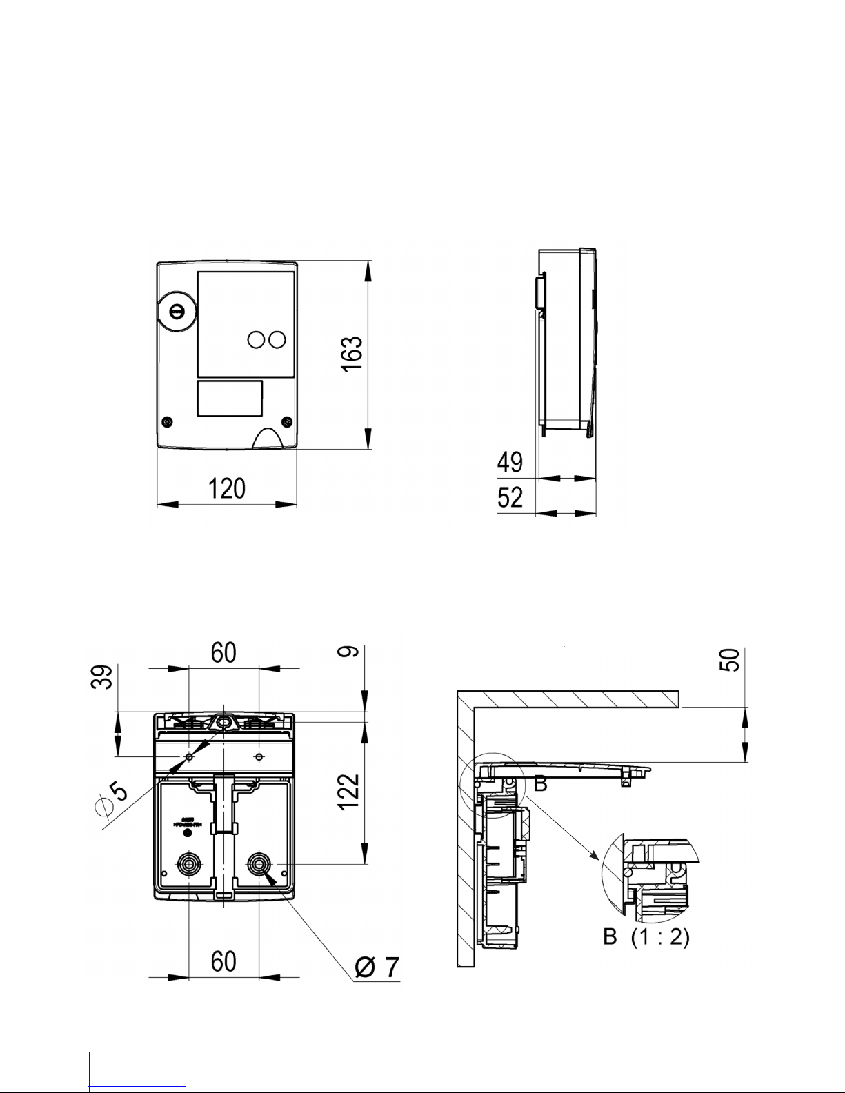
4 Installation
The CALEC® ST II can be mounted on a mounting rail or on a flat wall. Suitable mounting rails are available as
an accessory (article number 19838). Please refer to the last page of this document for a hole template for both
installation types.
Device dimensions
Hole dimensions for wall mounting Clear height
(for clipping on the housing cover)
Page 7
7
CALEC® ST II
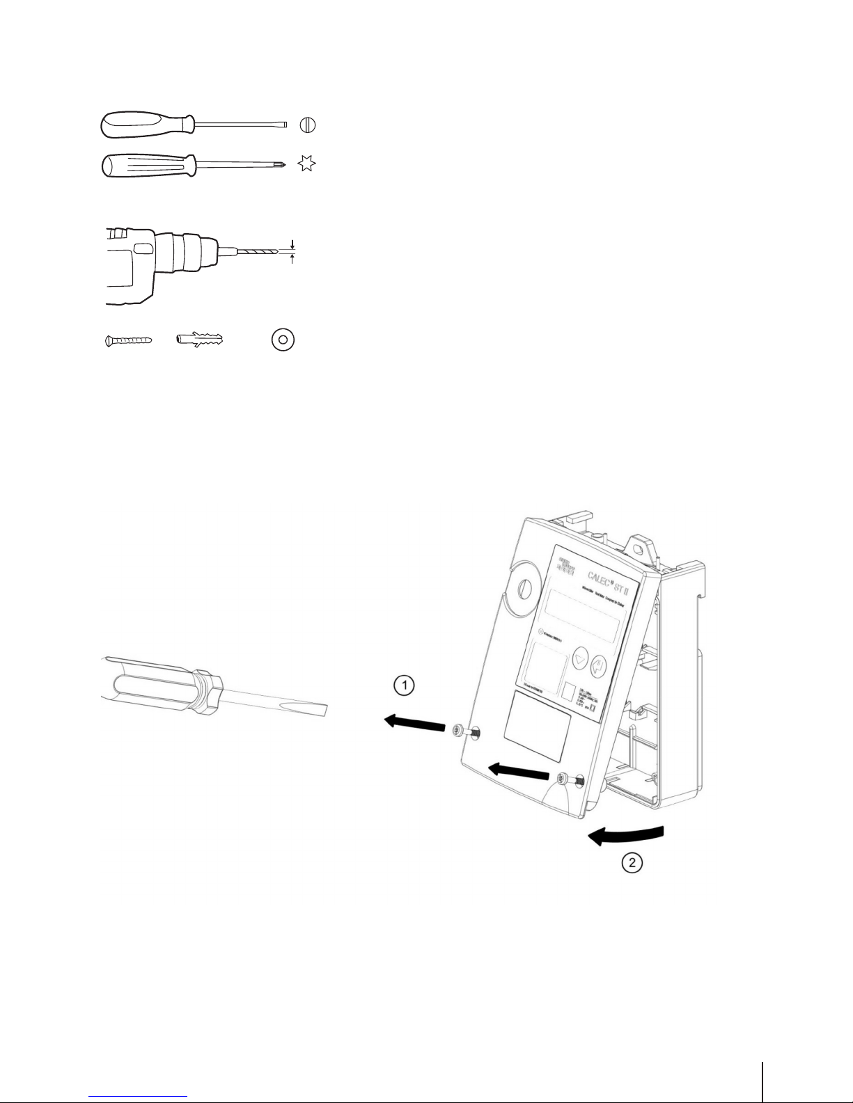
Tools, assembly materials
(Not included in the scope of delivery)
Opening the housing
3 x Ø
4
3 x Ø6
Torx T15
Ø6
3 x 4.3 x 12
3.5 x 0.6
Page 8
8
CALEC® ST II
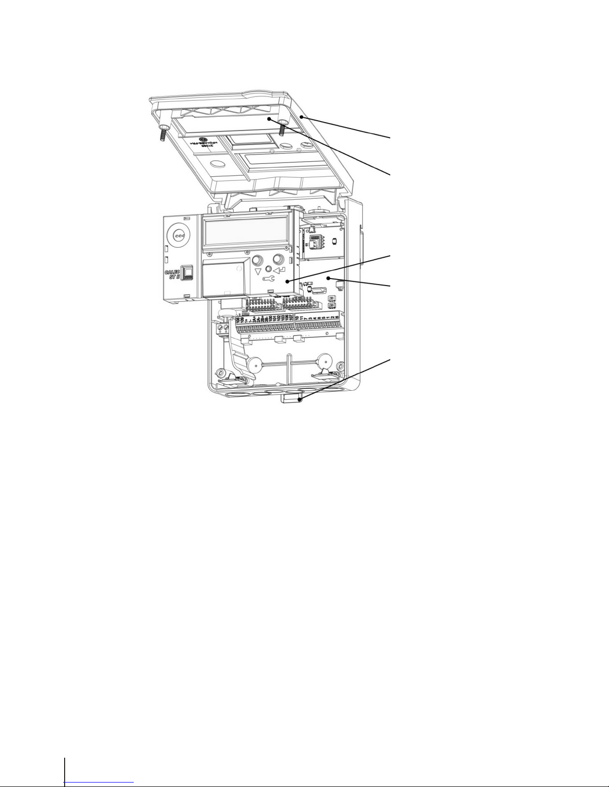
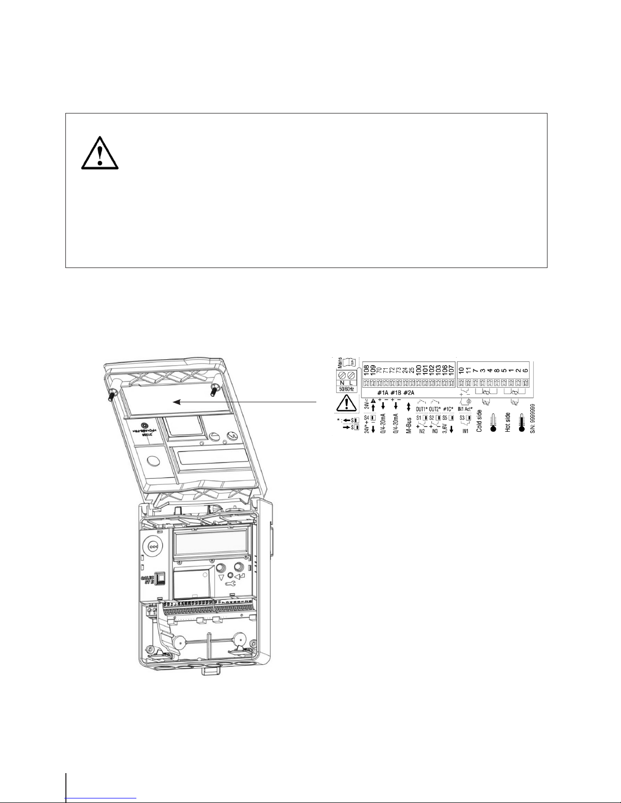
Unit design
À
The front cover can be locked into the lower section of the housing
Á
The connection diagram is located on the inside of the front cover
Â
The motherboard can be accessed by removing the plug-in totaliser
Ã
Motherboard with terminals and microswitches for configuring inputs and outputs
Ä
Clip-on holder for mounting rail
À
Á
Â
Ã
Ä
Page 9
9
CALEC® ST II
4.1 Installation
Installation instructions
Select the installation point:
• protected from moisture, heat, direct sunlight and damage
• easily accessible for reading, operation and installation
• at a sufficient distance from sources of electromagnetic interference
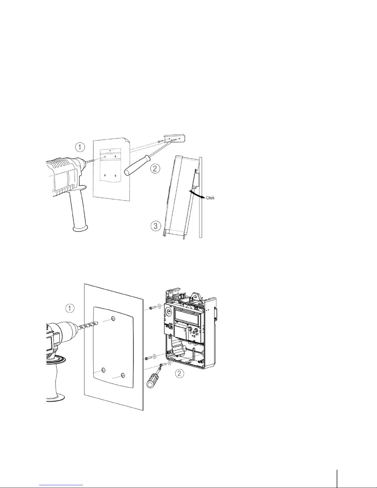
Mounting on rail DIN-EN 50222
À
Drill holes Ø6
Á
Screw in the mounting rail
Â
Clip the device onto the
mounting rail
Wall mounting
Only mount the device on
a flat surface!
À
Drill holes Ø6
Á
Screw in the device
Page 10
10
CALEC® ST II
4.2 Electrical connection
Hazard warning
Connection diagram
The connection diagram is located on the inside of the front cover.
Sample connection diagram:
Analogue outputs in socket #1 and M-Bus
in socket #2.
WARNING!
Danger of electrocution!
Touching or gripping live electrical parts can cause an electric shock, which may
result in burns, paralysis or death.
• The device should only be opened, installed or repaired when the power has been
switched off.
• Only specialist technicians are authorised to work on or with mains voltage.
They must comply with the applicable regulations.
• Only the screw-type terminals in the separated area on the left in the terminal
compartment should be used to connect the device to the mains supply.
Page 11
11
CALEC® ST II
Terminal technology
The CALEC® ST II is equipped with direct plug-in terminal connectors based on the “push-in” principle. Stripped
rigid conductors or flexible conductors with crimped ferrules (AEH) can be plugged directly into the spring terminal
to create a reliable, vibration-resistant and gas-tight connection. The release button has to be pressed for finestranded conductors, or to release the conductors.
Connectable conductors:
Single-conductor connection:
• Single-wire mm2: 0.50…1.50
• Finely stranded mm2: 0.50…1.50
• Finely stranded with AEH mm2: 0.25…1.50
• AEH with plastic collar mm2: 0.25…0.75
Stripping length mm: 8.0 + 1.0
AWG: 24-16
Functionality of connections
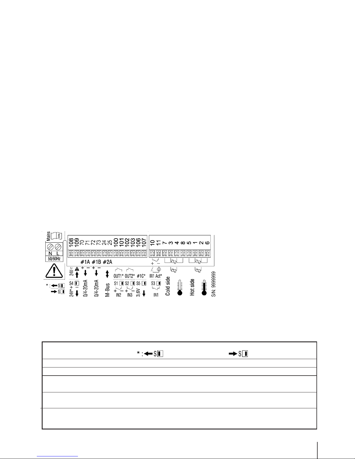
Connection diagram
The functionality of different connections can be configured with microswitches S1 - S5. The original factory
status is documented on the connection diagram. If required, the alternative functionality shown in the connection
diagram can be made available by switching the corresponding microswitch.
Sample connection diagram:
Analogue outputs in socket #1
and M-Bus in socket #2.
Overview of configuration options using microswitches
Terminals Switch Left function position Right function position
100 - 101 S1 OUTPUT#1 INPUT#2
102 - 103 S2 OUTPUT#2 INPUT#3
10 - 11 S3 INPUT#1: Active transmitter signal INPUT#1: Passive transmitter signal
(5 - 48 VDC) (e.g. reed)
108 - 109 S4 Sensor supply voltage Note: Consider section low voltage
supply (page 13)
106 - 107 S5 OUTPUT #1C Sensor supply voltage
3.6 V DC
Page 12
Supply voltage 100 - 240 V AC 50/60 Hz
l
Connections: L and N The supply voltage is connected via the two screw terminals in
accordance with on-site regulations.
The cable is passed through the diaphragm seal using
the enclosed piercing awl.
Voltage range: 100 - 240 V AC
Frequency range: 50/60 Hz
Power requirements: max. 15 VA
Connection cross-section: max. 2.5 mm
2
Cladding diameter: max. 8 mm
Heat resistance: min. 65°C
Connection to circuit with protection of max. 10A and
double-pole isolating element.
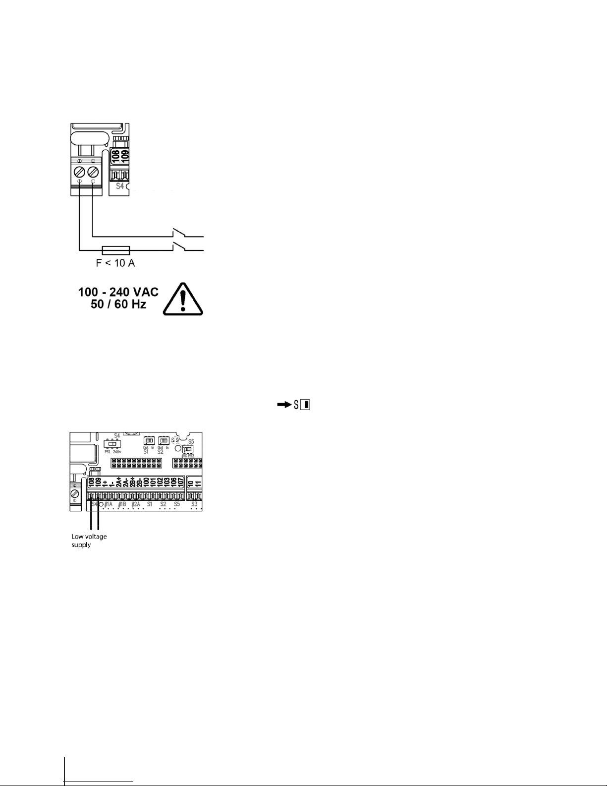
Low voltage supply 12 - 42 V DC or 12 - 36 V AC 50/60 Hz or 24 VDC ± 20%
l
Connections: 108 and 109 Switch S4 (24 V ~ )
The CALEC® ST II can be supplied with safe extra-low voltage via these
terminals.
Voltage range: 12 - 42V DC / 12 - 36V AC
Frequency range: 50/60 Hz
Power requirements: max. 1 VA
With adapter « insulated supply 24V-24V» (Art. no. 80828))
Voltage range: 24VDC ± 20%
Frequency range: 50/60 Hz
Performance range: max 1 W
12
CALEC® ST II
Page 13
13
CALEC® ST II
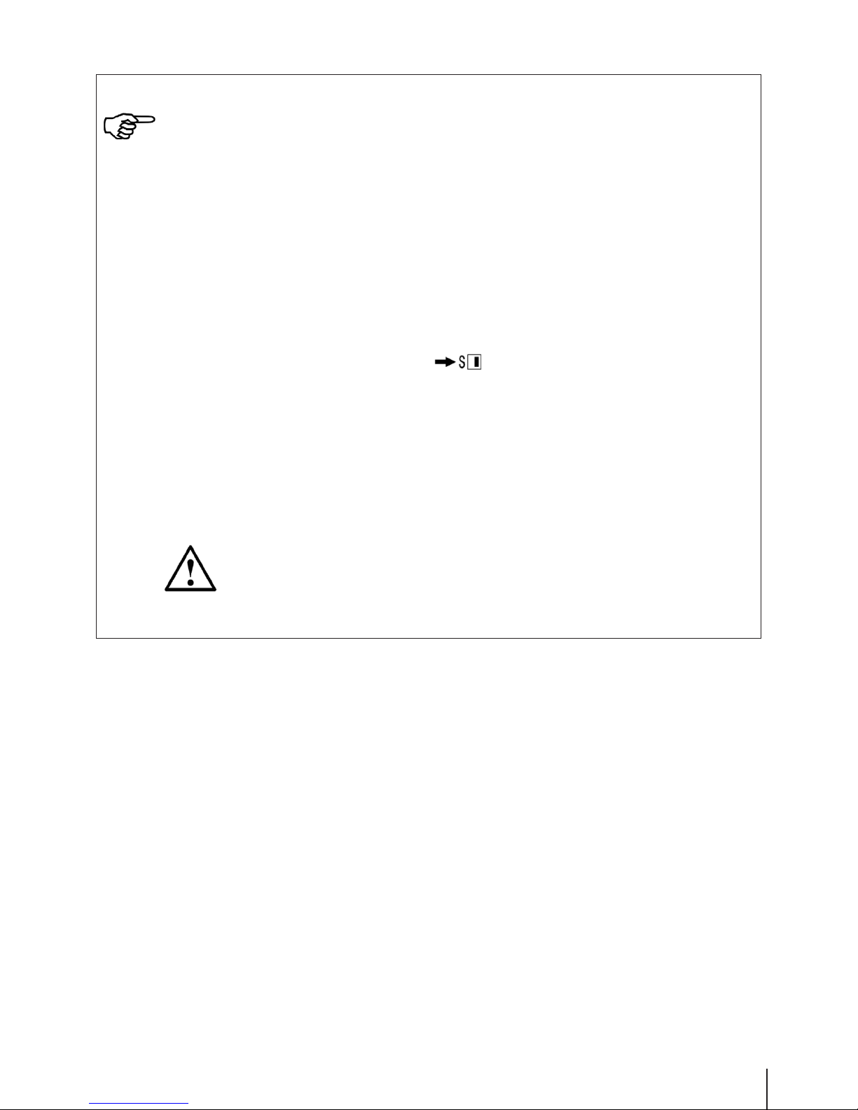
NOTE!
In low voltage applications of CALEC® ST II, in which a multiple grounding (PE) exists in field
installation, the adapter “insulated supply 24V-24V» (Art. no. 80828) must be positioned
upstream.
Examples for grounding:
• Grounded pulse input (e.g. pulser AMFLO® MAG Basic)
• Grounded sensor supply 3.6V and / or 24V
• Grounded pole of the low voltage supply
Procedure:
1. Disconnect CALEC® ST II from power supply
2. Set switch S4 from left to right
3. Connect adapter:
108+ from adapter to clamp 108 on CALEC® ST II
109- from adapter to clamp 109 on CALEC® ST II
IN+ and IN- from adapter to the external measuring point supply
Additionally the low voltage and sensor supply is possible with the adapter “insulated supply
24V-24V». Therefore the sensor shall be connected with OUT2+ and OUT2- (max. 150 mA).
If the switch is not correctly set, the device is later may not working properly or getting
destroyed.
The function low voltage supply shall only be used with the switch S4 in the position “right”!
Page 14
14
CALEC® ST II
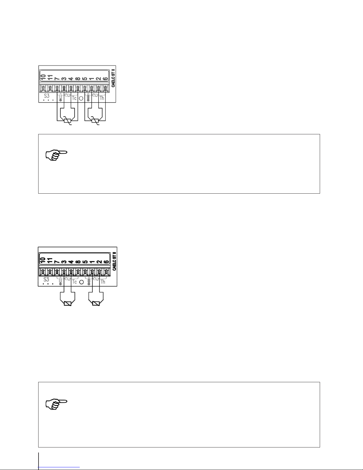
4-wire temperature sensor
l
Connections: 1 to 8
Check that the temperature sensor type (e.g. Pt500) corresponds to
the specifications of the CALEC® ST II.
Connection cross-sections: min. 0.22 mm
2
Cable length: max. 100 m
2-wire temperature sensor
l
Connections: 1, 2 and 3, 4
Check that the temperature sensor type (e.g. Pt500) corresponds to the
specifications of the CALEC® ST II.
Connection cross-sections:
Head sensor: min. 0.8 mm
2
Cable sensor: min. 0.22 mm
2
Cable length: shorter than 50 m (recommended)
Please note that the following maximum cable lengths are permitted for
2-wire technology, according to EN 1434-2:
Cable cross-section: Cable length:
Pt100 Pt500
min. 0.22 mm2 2.5 m 12.5 m
min. 0.50 mm2 5.0 m 25.0 m
min. 0.75 mm2 7.5 m 37.5 m
min. 1.5 mm2 15.0 m 75.0 m
NOTE!
Please check the connections carefully and ensure that the sensors are not reversed.
T
hot
terminals 1/5 and 2/6
T
cold
terminals 3/7 and 4/8
Temperature sensor cables must not be routed near power lines or electromagnetic inter-
ference sources (min. 50 cm distance).
NOTE!
The length of signal cable supplied by the manufacturer must not be changed.
Please check the connections carefully and ensure that the sensors are not reversed.
T
hot
terminals 1 and 2
T
cold
terminals 3 and 4
Temperature sensor cables must not be routed near power lines or electromagnetic inter-
ference sources (min. 50 cm distance).
Page 15

15
CALEC® ST II
Sensor supply voltage 24 V DC
l
Connections: 108 and 109 Switch S4 (PS1)
When switch S4 is in the left-hand position (PS1), terminals 108/109
have a 24 V DC power supply for supplying a flow transmitter, e.g.
AMFLO® MAG Smart.
Output voltage: 24 VDC, electrically isolated
from all other outputs
Load: max. 150 mA
Electrical isolation: max. 48 VDC
Sensor supply voltage 3.6 V DC
l
Connections: 106 and 107 Switch S5 (PS2)
When switch S5 is in the right-hand position (PS1), terminals 106/107
have a 3.6 V DC power supply for supplying a flow transmitter, e.g.
AMFLO® SONIC UFA113.
Output voltage: 3.6 VDC, not electrically isolated
Load: max. 2 mA
NOTE!
When the sensor power supply is not needed, it can also be used for the active supply
of the current outputs (optional). If multiple current outputs are supplied, please note
that these are no longer electrically isolated from each other.
NOTE!
Terminal 107 is connected to terminal 11 and establishes the reference potential
for the flow transmitter.
Page 16
16
CALEC® ST II
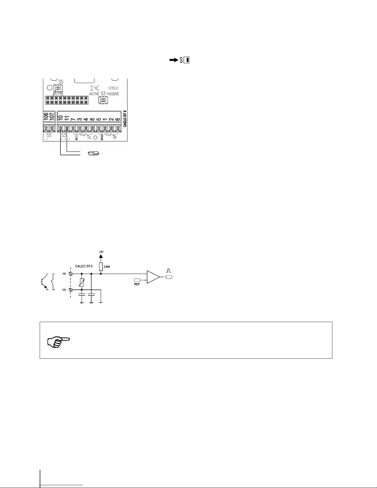
Flow transmitter with passive signal on pulse input #1
l
Connections: 10 and 11 Switch S3 (PASSIVE)
When switch S3 is set to the right-hand position (PASSIVE), a flow
transmitter with passive pulse signals, such as a reed relay or SSR
(solid state relay), can be connected to terminals 10 and 11.
The pulse signal from the flow transmitter must comply with the
following specifications:
Open-circuit voltage: 8 V
Short-circuit current: 8 mA
Switching level: <1.5 mA, >2.1 mA
Input capacity: 20 nF
Frequency range: 0…20 Hz 0…200 Hz
Min. OFF (toff): 20 ms 2 ms
Min. ON (ton): 3 ms 300 μs
The programming options for this input are described in the “InPutS”
of chapter „Operation“.
Diagram of input circuit
NOTE!
Flow transmitter cables must not be routed near power lines or electromagnetic interfe-
rence sources (min. 50 cm distance).
Page 17
17
CALEC® ST II
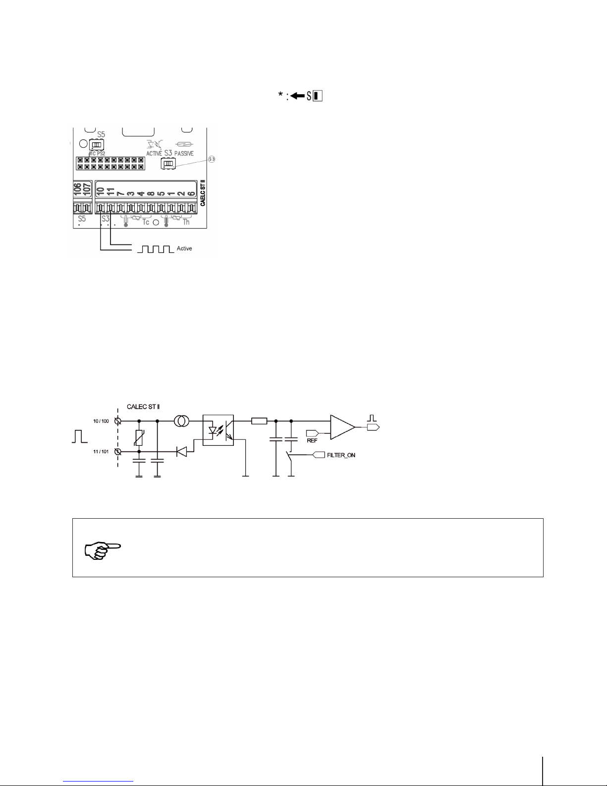
Flow transmitter with active signal on pulse input #1
l
Connections: 10 and 11 Switch S3 (ACT)
Switch S3 must be moved to the left-hand position (ACT) for flow
transmitters with an active signal.
The pulse signal from the flow transmitter must comply with the
following specifications:
Voltage range: 3...48 VDC
Current signal: > 2 mA
Reverse polarity protection: -48 V
Electrical isolation: 48 V
Frequency range: 0…20 Hz 0…200 Hz
Min. OFF (toff): 20 ms 2 ms
Min. ON (ton): 3 ms 300 μs
The programming options for this input are described in “InPutS”
of chapter „Operation“.
Diagram of input circuit
NOTE!
Flow transmitter cables must not be routed near power lines or electromagnetic interfe-
rence sources (min. 50 cm distance).
Page 18

18
CALEC® ST II
Connection examples for flow transmitters on pulse input #1
a) Connection example for TOPAS PMG/PMH flow transmitter
l
Connections: 10 and 11 Switch S3 (PASSIVE)
The TOPAS PMH transmits a
passive pulsed signal when
switch S3 is in the right-hand
position (PASSIVE).
b) Flow transmitter AMFLO® SONIC UFA113 with supply
l
Connections: 10, 11 and 106, 107 Switch S5 (PS2)
Switch S3 (PASSIVE)
The AMFLO® SONIC UFA113
is supplied with 3.3 V DC via
terminal 106 and 107 when
switch S5 is in the right-hand
position (PS).
The AMFLO® SONIC UFA113
transmits a passive pulsed signal
when switch S3 is in the
right-hand position (PASSIVE).
Connections 11 and 107 are
connected internally, which
means that the connection
can be made using only
3 wires.
+
–
Page 19

19
CALEC® ST II
c) AMFLO® MAG Smart / MAG Basic flow transmitter with grounding (standard)
l
Connections: 108, 109, 10 and 11 Switch S4 (PS1)
Switch S3 (PASSIVE)
Set switch S4 to the left-hand
position (PS) so that the
AMFLO® MAG Smart is supplied
with 24 V DC via terminals
108 and 109.
The AMFLO® MAG Smart
transmits a passive pulsed
signal when switch S3 is in
the right-hand position (PASSIVE).
d) AMFLO® MAG Smart / MAG Basic flow transmitter with two groundings
l
OUT2+, OUT2-, 10 and 11 Switch S4 (=24V)
Switch S3 (PASSIVE)
CALEC® ST II is supplied with 24
VDC via the adapter «insulated sup ply 24V-24V» (Art. no. 80828) IN+
and IN- over the clamps 108 and
109. Therefore the switch S4 needs
to be switched to the “right” (24V).
AMFLO® MAG Smart is supplied
with 24 VDC via OUT2+ and OUT2-
at the adapter «insulated supply
24V-24V».
AMFLO® MAG Smart is emitting
a passive pulse signal,
for which the switch S3 shall be
switched to the „right“ (PASSIVE).
NOTE!
See note low voltage supply (page 13)
Page 20

20
CALEC® ST II
Pulse input #2
l
Connections: 100 and 101 Switch S1 (in)
Terminals 100 and 101 can be used as the 2nd pulse input
when switch S1 is set to the right-hand position (In).
The data correspond to pulse input 1 for passive pulse
transmitters on terminal 10 and 11.
The programming options for this input are described in the
“InPutS” of chapter „Operation“.
Pulse input #3
l
Connections: 102 and 103 Switch S2 (in)
Terminals 102 and 103 can be used as the 3rd pulse input
when switch S2 is set to the right-hand position (In).
The pulse signal from the pulsed transmitter must comply
with the following specifications:
Frequency range: 0…20 Hz
ton: ≥ 50 µs
t
off
: ≥ 50 µs
Switching thresholds:
RON: ≤ 20 Ω
R
OFF
: ≥ 1 MΩ
The programming options for this input are described in the
“InPutS” of chapter „Operation“.
Diagram of input circuit
Page 21

21
CALEC® ST II
Digital output (pulse, status, alarm) #1
l
Connections: 100 and 101 Switch S1 (Out)
Terminals 100 and 101 are used as digital output 1 when
switch S1 is set to the left-hand position (Out).
Switching voltage: max. 48 V DC, 36 V AC
Switching current: max. 100 mA
RON: < 25 Ω
R
OFF
: > 1 MΩ
Electrical isolation: max. 48 V DC
Pulse frequency: max. 4 Hz
Pulse width: 100 ms
The programming options for this input are described in the
“OutPutS” of chapter „Operation“.
Diagram of input circuit
Digital output (pulse, status, alarm) #2
l
Connections: 102 and 103 Switch S2 (Out)
Terminals 102 and 103 are used as digital output 2 when
switch S2 is set to the left-hand position (Out).
Data as per digital output signal 1.
Page 22

Module slots
Connection diagram
CALEC® ST II is equipped with 2 separate slots for optional communication or function modules. Depending on
the equipment fitted to the device, these 2 slots provide various connection options on outputs #1A, #1B and
#2A. The connection diagram and the terminal numbers shows the optional communication or function modules
which are fitted to the device.
Sample connection diagram:
Analogue outputs in socket #1 and M-Bus in socket #2.
Function overview of outputs #1A, #1B and #2A
Optional communication and function modules
Communications modules can be connected to either slot #1 or #2.
It is preferable to use the function module with 2 analogue outputs in slot #1, because both channels are connected to terminals. In principle, the analogue output can also be used in slot #2. However, only one analogue output is
available on the terminals in this case. It is therefore preferable to use slot #2 for the first communication module.
22
CALEC® ST II
Function Terminals Available on output
M-Bus 24 - 25 #2A and / or #1A
Modbus RTU (RS 485) 90a - 91b #2A and / or #1A
BACnet MS/TP (RS 485) 90a - 91b #2A and / or #1A
N2Open (RS 485) 90a - 91b #2A and / or #1A
LON TP/FT-10 90a - 97b #2A and / or #1A
4 - 20 mA / 0 - 20 mA 70 - 71 #1A and / or #2A
4 - 20 mA / 0 - 20 mA 72 - 73 #1B
Page 23

23
CALEC® ST II
Analogue module in socket #1
For devices with 2 analogue outputs, the analogue module is fitted to socket #1.
l
Connections: 70, 71, 72 and 73
If an analogue module is connected to socket #1, there are 2 passive
analogue outputs via terminals 70/71 (#1A) and 72/73 (#1B).
The analogue outputs are electrically isolated.
Current range: 4...20 mA or 0...20 mA
Supply voltage: 6...24 V DC
Electrical isolation: max. 48 V DC
Resistance: ≤ 837 ohms at 24 V DC
The programming options for this output are described in “I-OUT”
of chapter „Operation“.
Analogue module in socket #2
l
Connections: 70 and 71 (#2A)
If an analogue module is connected to socket #2,
there is one analogue output via terminals 70 and 71 (#2A).
Data as per the analogue module in socket #1.
Resistance
Page 24

24
CALEC® ST II
M-Bus Modul
M-Bus-Modul in Socket #2
Slot #2 is used for the first communication module.
l
Connections: 24 and 25 (#2A)
M-bus is connected via terminals 24 and 25 (#2A).
The primary and secondary address, and the baud rate,
can be set under “M-BuS”.
The interface is electrically isolated.
Factory settings:
Primary address: 0
Secondary address: Serial number
Baud rate: 2,400 baud
M-Bus module in socket #1
l
Connections: 24 and 25 (#1A)
The wiring for the second M-Bus interface is via terminals
24 and 25 (#1).
The specifications are the same as for the first M-Bus.
The settings for the first and second M-Bus can be programmed
independently.
REFERENCE!
The M-Bus protocol is described in detail in a separate document,
which is available on the following website:
http://www.aquametro.ch/qr/prod/calec-st/11111.html
Page 25

25
CALEC® ST II
LON-Modul
LON module in socket #2
Slot #2 is used for the first communication module.
l
Connections: 96a and 97b (#2A)
The twisted pair wiring is via terminals 96a and 97b (# 2A) and
is not poled.
The interface is electrically isolated.
The service PIN and the Wink LED are available for identification
on the LON network.
The service LED provides information about the system
status.
LON module in socket #1
l
Connections: 96 and 97 (#1A)
The twisted pair wiring for the second LON interface is via terminals
96a and 97b (#1A).
The specifications are the same as for the first LON interface.
REFERENCE!
The LON TP-FT 10 interface is described in detail in a separate
document, which is available on the following website:
http://www.aquametro.ch/qr/prod/calec-st/11111.html
An XIF file is also available at www.lonmark.org
Wink LED
Service PIN
Service LED
Page 26

BACnet MS/TP Modul
BACnet MS/TP module in socket #2
Slot #2 is used for the first communication module.
l
Connections: 90a+ and 91B- (#2A)
The twisted pair wiring is via terminals 90a and 91b (#2A).
The BACnet MAC address, device instance number, mode and baud rate
can all be set under “BACnet”. If the CALEC® ST II is at the end of the
BACnet-segment, the internal termination resistor can be used.
The interface is electrically isolated.
Factory settings:
Aquametro manufacturer ID: 431
BACnet device profile: B-ASC
BACnet MAC address: Last 2 digits of the serial number
Device instance number: Last 5 digits of the serial number
Mode: Master
Baud rate: Automatic
BACnet MS/TP module in socket #1
l
Connections: 90a+ and 91b- (#1A)
The twisted pair wiring for the second BACnet inter-face is via terminals
90a+ and 91b- (#1A).
The specifications correspond to the first BACnet interface.
26
CALEC® ST II
REFERENCE!
The BACnet MS/TP protocol is described in detail in a separate
document, which is available on the following website:
http://www.aquametro.ch/qr/prod/calec-st/11111.html
The PICS document can also be found there.
Page 27

27
CALEC® ST II
Modbus RTU Modul
Modbus RTU module in socket #2
Slot #2 is used for the first communication module.
l
Connections: 90a+ and 91b- (#2A)
The twisted pair wiring is via terminals 90a+ and 91b- (#2A).
The address, baud rate and parity can be set under “ModbuS”.
If the CALEC® ST II is at the end of the Modbus-segment, the internal
termination resistor can be used.
The interface is electrically isolated.
Factory settings:
Modbus address: 1
Baud rate: 19200 baud
Parity: Even
Modbus RTU module in socket #1
l Connections: 90a+ and 91b- (#1A)
The twisted pair wiring for the second Modbus interface is via
terminals 90a+ and 91b- (#1A).
The specifications are the same as for the first Modbus interface.
REFERENCE!
The Modbus RTU interface is described in detail in a separate
document, which is available on the following website:
http://www.aquametro.ch/qr/prod/calec-st/11111.html
Page 28

28
CALEC® ST II
METASYS® N2Open Modul
METASYS® N2Open module in socket #2
For devices with a communication module, this is fitted to socket #2.
l
Connections: 90a+ and 91b- (#2A)
The twisted pair wiring is via terminals 90a and 91b (# 2A). The address
and the baud rate can be set under “n2-buS”.
If the CALEC® ST II is at the end of the N2Open-segment, the internal
termination resistor can be used.
The interface is electrically isolated.
Factory settings:
N2Open address: 1
Baud rate: 9600
METASYS® N2Open module in socket #1
l
Connections: 90a+ and 91b- (#1A)
The twisted pair wiring for the second N2Open interface is via
terminals 90a+ and 91b- (#1A).
The specifications are the same as for the first N2Open interface.
REFERENCE!
The METASYS® N2Open Interface is described in detail in a separate
document, which is available on the following website:
http://www.aquametro.ch/qr/prod/calec-st/11111.html
Page 29

29
CALEC® ST II
Connecting the mains voltage
Hazard warning
WARNING!
Danger of electrocution!
Touching or gripping live electrical parts can cause an electric shock, which may result
in burns, paralysis or death.
• The device should only be opened, installed or repaired when the power has
been switched off.
• Only specialist technicians are authorised to work on or with mains voltage.
They must comply with the applicable regulations.
• Only the screw-type terminals in the separated area on the left in the terminal
compartment should be used to connect the device to the mains supply.
NOTE!
Calibrated device!
• The device must be protected by an external overcurrent protective device
(max. 10A) so that the unit shuts down safely in the event of an electrical fault.
The power supply must be designed to ensure that it has adequate protection
against intentional interruption and that it can be shut down for maintenance.
• A marked 2-pole isolating device is mandatory. Alternatively, a 2-pole isolating
overcurrent protective device can be used. However, it must not be possible to the
circuit for the totaliser to be disconnected independently of the heating or cooling
system.
• The connection cable must have a temperature resistance > 65°C.
Page 30

30
CALEC® ST II
(A) Power supply terminal
(B) External isolating device
(C) External protection
The power supply is connected to the screw terminals (A).
After tightening the terminals, check that the wires are clamped securely.
Tighten the strain relief, check that it is functioning correctly.
Page 31

31
CALEC® ST II
Closing the housing
Insert the cover into the hinge from above and turn to close.
Tighten the two fixing screws.
The screws can be secured. Once the security sealing caps stored
on the top of the housing have been fitted, any unauthorised opening
of the device can be detected. Engage the security sealing caps with
the smooth side on the outside.
Page 32

32
CALEC® ST II
5 Controls and operation
5.1 Content of this manual
This manual only contains details of the operating steps required to perform a function check.
5.2 Controls
Cover
Liquid crystal display
(LCD)
Enter key
Select key
Nameplate, if verified with
calibration
Optical M-Bus interface /
alarm signal display
(flashing red)
Service key
Nameplate of totaliser module
Housing screws covered by
safety caps
REFERENCE!
Related documents!
Related documents can be found on the following website:
http://www.aquametro.ch/qr/prod/calec-st/11111.html
Page 33

33
CALEC® ST II
5.3 Display
5.4 Operating modes
The operating keys and display enable all relevant settings to be carried out without using peripheral units.
The settings are arranged in three security levels (lock levels).
Various data can therefore be altered depending on the operating mode.
User mode:
When the housing is closed, freely accessible data can be shown in the display using the keys.
Service mode:
This can be activated by pressing the service key when the cover is open. It also enables all necessary but
non-verifiable startup parameters to be set and displayed.
Programming mode:
This enables the complete range of settings, including calibrated values, to be made.
This can be activated only if the leaded seal has been destroyed. It is not described in these instructions.
Flow
indication
Alarm indication
Places after the
decimal point
Service
mode
Edit
mode
User
mode
Memory
Identification 8 character decimal field Units
Page 34

34
CALEC® ST II
5.5 Key functions
When the device is switched on, the display shows the energy reading in the Counter loop. Additional readings
can be displayed by pressing the Select button. The “Counter” menu is displayed once you have scrolled through
all readings. Press the Enter button to display the Counter loop again. The other available main menus can be
selected by pressing the Select button. Press the Enter button to display the relevant menu loop.
The main loop shows the key readings and allows you to navigate through the sub-loops. In addition, highresolution meter readings can be displayed by pressing the two buttons simultaneously.
Keys Function
Next field
Higher value
Accept the set value
Accept the selected value
Hold + for longer than 1s Return to the standard “Counter” display
Hold , press High-resolution display
Hold , press Previous field
Lower value
The Service button activates Edit mode
Page 35

35
CALEC® ST II
5.6 Display and menu structure
The following double pages shows the menu structure.
Legend:
Note!
Fields marked with * are only visible when the device has the corresponding option
(Mass, PDA, TGR, tariff & BDV, Flow, GLY).
Field visible
Field visible under certain
conditions
Field in service mode
editable
Field in programming mode
editable
Field in Init mode
editable
white
grey 15%
grey 35%
Page 36

36
CALEC® ST II
Menu description
Display Definition
Counter Counters
E Energy meter reading
V Volume meter reading
M Mass meter reading (optional)
E2 Energy meter 2 reading (optional BDE/TGR)
V2 Volume meter 2 reading (optional BDE)
E3 Energy meter 3 reading (optional TGR)
H1 Auxiliary counter 1 reading (optional Flow)
H2 Auxiliary counter 2 reading
H3 Auxiliary counter 3 reading
Imp Pulse value flowmeter
Sid Installation side flowmeter
Display Definition
INFO Error messages
SYSt-Err Error system
U-Err Error supply
th-Error Error temperature sensor hot side
tc-Error Error temperature sensor cold side
MEM-Err Memory error (HW)
OPT-Err Error on one of the option modules (HW)
th-ALArM Temperature on hot side outside the permitted range
tc-ALArM Temperature on cold side outside the permitted range
dt-ALArM Temperature difference outside the permitted range
Ext-AL External Alarm
XX888XXX Display test
Page 37

37
CALEC® ST II
Display Definition
Instant Current values
Th Temperature hot side
(For cooling = Return line)
Tc Temperature cold side
(For cooling = Supply line)
dT Temperature difference
P Power
Qv Flow
Qm Mass flow
KF Specific heat factor
DEN Density
Display Definition
TIME Time-parameters
DAT Date
TiM Time
DAY Day
SEA Summer or Winter time
Hr Operating hours
AL Hours of alarm
Err Hours of error
Pb Calibration year
Page 38

38
CALEC® ST II
Menu description
Display Definition
Stich Billing date values
Nr Billing date number 1 - 12
St Billing date 1 - 12
DAT Date
E Energy meter reading
V Volume meter reading
M Mass meter reading
E2 Energy meter reading 2,
in options BDE / BDV
V2 Volume meter reading 2,
in options BDE / BDV
E3 Energy meter reading 3,
in option TGR
H1 Auxiliary meters reading 1,
in option Flow
H2 Auxiliary meters reading 2
H3 Auxiliary meters reading 3
AL Alarm hours
ERR Error hours
Display Definition
LOGGEr Logger data
Nr Logger number
Per memory interval
DAT Date
E Energy meter reading
V Volume meter reading
M Mass meter reading
E2 Energy meter reading 2
in options BDE / BDV
V2 Volume meter reading 2
in options BDE / BDV
E3 Energy meter reading 3
in option TGR
H1 Auxiliary meters reading 1,
in option Flow
H2 Auxiliary meters reading 2
H3 Auxiliary meters reading 3
Page 39

39
CALEC® ST II
Display Definition
Inputs Parameters for input signals
Nr Input number
Fct Input Function
ImP Puls value of the flow meter
Sid Installation side of the flow meter
(th = hot side, tc = cold side)
F Maximum frequency
STA Actual status
MAX Upper limit for th / tc alarm
MiN Lower limit for th / tc alarm
Tr Threshold for return temperature
in option TGR
Overstepping: register E2
Undercutting: register E3
Page 40

40
CALEC® ST II
Menu description
Display Definition
Outputs Parameters for digital output signals
Nr Output number
Fct Output Function
SIG Type of the output
ImP Pulse value of the output
GW1 Limit 1
GW2 Limit 2
Hys Hysteresis
Cnt Pulse counter / Seconds of overstepped
limit value
Act Direction of action
STA Actual status
Display Definition
I-Out Parameters for analogue output signals
Nr Output number
Fct Output Function
SIG Type of the output
0/4 Value at 0 mA
20 Value at 20 mA
do Simulation mA value
Err Current output in case of error
STA Current value
Page 41

41
CALEC® ST II
Page 42

42
CALEC® ST II
Menu description
Display Definition
UnitS Units
Eu Energy unit
Ed Number of decimal places on the display for energy
V Number of decimal places on the display for volume
M Number of decimal places on the display for mass
P Power unit
Q Volume flow unit
T Temperature unit
EP Pulse value for energy pulse output
VP Pulse value for volume pulse output
Display Definition
M-BuS M-Bus parameters
Nr M-Bus number
(1 = Socket #1, 2 = Socket #2,
3 = optical interface)
Adr Primary M-Bus address
SEK Secondary M-Bus address
BAU Baud rate
Acc Access counter
APP M-Bus application reset
Page 43

43
CALEC® ST II
Display Definition
ModbuS Modbus-Parameter
Nr Modbus number (1 = Socket #1, 2 = Socket #2)
Adr Modbus address
BAU Baud rate
Par Parity
TRN Termination resistor ON / OFF
n2-buS N2Open parameters
Nr Number (1 = Socket #1, 2 = Socket #2)
Adr Address
TRN Termination resistor ON / OFF
Display Definition
BAcnEt BACnet-parameters
Nr Number (1 = Socket #1, 2 = Socket #2)
Adr Address
Mod Mode (Master /Slave)
DIN BAcnEt Device Instance Number
TRN Termination resistor ON / OFF
Page 44

44
CALEC® ST II
Menu description
Display Definition
CONFIG
TYP Type temperature sensors (PT 100 etc.)
MEd Heat carrier (medium) in option Glycol
Con Concentration of heat carrier in option Glycol
SMU Low flow cut off
Rem Remanence (time of display of
instantaneous Values)
Display Definition
CONFIG
dPQ Attenuation factor for power and flow
dPt Attenuation factor for temperature
Loc Lock levels
RES Reset of alarms and counters
(depending on lock level)
dt- Adjustment of minimal temperature difference alarm
dtc Sensor alignment
Page 45

45
CALEC® ST II
Display Definition
SYStEM
FNr Fabrication number
SYS Functionality of the calculator
DAT Date of manufacture
FW Firmware version
HW Hardware version
CS Checksum
Page 46

46
CALEC® ST II
NOTE!
Unit!
If the option once-only on-site adjustment of the calibration-related input variables
“IMP EBS” is used, ensure that the selected unit can display the amount of energy
accumulated during the calibration period without counter overflow.
Init-Mode: Once-only on-site adjustment
Menu description
Display Definition
INIT Depending on the model it is possible to program
in the „INIT-Mode“ ImP/Sid/Eu/Ed once-only
Go After conforming the settings they can‘t be
changed any longer
Page 47

47
CALEC® ST II
5.7 Commissioning
Startup
• Check the electrical connections.
• Turn on the power supply.
• Any error/alarms which appear must be fixed, (see Info loop and error messages).
• Press the select button until the display shows “ImP”, and check the pulse value of the flow transmitter.
• Press the select button until the display shows “Sid”, and check the installation side of the flow transmitter.
• Following startup, close the housing and secure the screws with the protective plugs.
(Sealing of calibrated measuring points)
• Give this operation manual to the user or leave it with the device.
Function control
• Check the main input unit, or set it up for an auxiliary meter (see Units loop).
• Check the pulse value of the main input, or set it up for an auxiliary meter (see Input loop).
• Check and/or set the date and time (see Time loop).
• If there is a flow, the wave symbol flashes in the top left of the display.
• Check whether plausible instantaneous values are displayed during unit operation (see Instant loop).
• The display reset time (to zero) and the filter characteristics for the instantaneous values of Q and/or
P can be set in the Config loop.
Page 48

48
CALEC® ST II
5.8 Error messages, alarms
If a fault occurs, the message “Alarm” will appear on the display above the number pad. The optical M-Bus interface also flashes red to indicate the alarm message.
The short message in the information loop gives details of the reason for the fault/alarm.
Message Error/alarm Possible cause Corrective measures
th-ERROR Temperature error • Sensor connected • Check wiring
on hot side, incorrectly • Check disconnected
no measurement • Interruption/short circuit sensor wires with ohm
possible in sensor cables meter
• If OK, check the input
input with a resistor:
Pt 100: 100 - 150Ω
Pt 500: 500 - 620Ω
tc-ERROR Temperature error As above As above
on cold side,
no measurement
possible
SYSt-Error EEPROM Component/device error Send the device to
memory error be checked
th-ALArM Temperature on the Temperature of the heat Check the current
hot side is outside cycle is too high or temperature in the InStAnt
the permitted too low submenu
measuring range
tc-ALArM Temperature on the As above As above
cold side is outside
the permitted
measuring range
dt-ALArM Temperature difference • Temperature difference Check the current
is outside the permitted in the heat cycle temperature difference
measuring range is too large or is negative in the InStAnt submenu
• Sensor problem
Page 49

49
CALEC® ST II
6 Maintenance and repair
6.1 Recalibration
In accordance with national legislation on weights and measures, periodic recalibration is required for devices in
commercial use which are subject to mandatory verification. The recalibration interval for energy meters is usually
5 years.
All calibration-related functions on the CALEC® ST II can be found on the plug-in totaliser module. This means
that recalibration can be carried out by simply replacing the totaliser module. The lower section of the housing
containing the field wiring does not have to be removed during calibration. The parameter settings specific to the
device are stored redundantly in the lower section of the housing and are loaded automatically when a replacement
totaliser module is plugged in. Reparametrisation of the device is not required. When processing the readings,
however, remember to ensure that the readings on the replacement totaliser module are reset to 0.
Plug-in totaliser module
7 Disposal
The device contains electronic components and must therefore be disposed of as
electronic waste.
Aquametro takes back its old devices and will dispose of them. Please also note
your local regulations in this respect.
Page 50

50
CALEC® ST II
8 Technical data
The following tables contain information on the technical data of the available functions. Please refer to the price
list for possible combinations.
Standards
CE directives
20
14/32/EU Measuring Instruments Directive (MID)
20
14/30/EU Electromagnetic compatibility (EMC)
20
14/35/EU Low voltage (LVD)
20
12/19/EU Waste Electrical and Electronic Equipment (WEEE) Directive
Standards EN 1434, EN 61000-6-1, EN 61000-6-2, EN 61010, DIN 43863-5
Housing and operating conditions
Dimensions W x H x D = 120 x 163 x 49 mm
Ambient temperature +5...+55 °C, EN 1434 class C
Storage temperature 0...60 °C
Humidity Max. 95% rel. humidity (non-condensing)
Operating altitude Up to 2,000 m above sea level
Protection rating IP 54
Terminals 1.5 mm2 spring terminals, Power connection 2.5 mm2 screw terminals
Basic data for calculator
Temperature measuring range 0...+200 °C (heat carrier: water)
-40...+180 °C (special heat carrier)
Temperature difference 0...190 K, Approval 3...190 K, on demand 2...190 K
Temperature sensor Pt100 or Pt500 in accordance with IEC 751 paired in accordance
with EN 1434, 2-wire or 4-wire connection. Max. sensor cable length
2-wire connection 10 m, 4-wire connection 15 m.
Temperature measurement 20-bit resolution, typical ±0.005 K (Ta = 5...55 °C)
resolution
Installation side Hot or cold side
Pulse value of the flow sensor 0.001...9999.999 litres
Pulse values and units for Volume: 0.001...9999.999 ml, l, m3 , GAL
auxiliary inputs and Energy: 0.001...9999.999 Wh, kWh, MWh, MJ, KBTU
contact outputs
Error limits Better than those required for calculators in accordance with EN 1434-1.
Suitable for combined class 2 heat meters in accordance with
EN 1434-1 when used with suitable volume metering units.
Optical interface IEC 870-5, M-Bus protocol
Page 51

51
CALEC® ST II
Mains version
Power supply 100 - 240 V AC, 50/60 Hz, max. 15 VA (in accordance with EN 1434)
12 - 42 VDC or 12 - 36 VAC, max. 1 VA (according to EN 1434)
At supply via adapter «insulated supply 24V-24V» (Art. no. 80828)
24 VDC ±20%, max. 7 Watt (at adapter)
Calculation cycle 1 s
Backup battery 3.6 V lithium battery
Additional functions
Adjustable low flow cut-off Function for stopping the energy calculation when the temperature
(SMU) difference is too low, ΔT SMU adjustable ΔT = 0 - 2.99 K
Limit-value monitoring One-sided or two-sided, hysteresis 0 - 10%,
action of the output signal is selectable
Display
Display units: volume m3, USGal
Display units: energy kWh, MWh, MJ, GJ, KBTU, MBTU
Data backup in the event of In EERPOM >10 years
a power failure
Data logger 500 values from all readings with a time stamp, stored in ring memory
Logger interval: 1 min, 1 hour, 1 day, 1 week, 1 month
Low-voltage power supply for flow transmitter
Terminals 108 / 109 (depending
on the version) Terminals 106/ 107
Supply voltage 24 V DC, max.150 mA, 3.6 VDC, max. 2 mA
el. isolation max. 48V V DC
Flow transmitter e.g. AMFLO® MAG Smart or e.g. AMFLO® SONIC UFA 113
active sensors
Page 52

52
CALEC® ST II
Pulse inputs and outputs
Main input #1 Connecting a pulse generator according to NAMUR, with potential-free contact
(10/11) (reed relay) or SSR (solid state relay), or for active sensors with the following
values.
Input passive Input active
Open-circuit voltage 8 V Voltage range 3...48 V DC
Short-circuit current 8 mA Current signal > 2 mA
Switching level <1.5 mA, >2.1 mA Reverse polarity protection -48 V
Min. OFF (t off) 20 Hz 20 ms Electrical isolation 48 V
Min. ON (t on) 20 Hz 3 ms Min. OFF (t off) 20 Hz 20 ms
Min. OFF (t off) 200 Hz 2 ms Min. ON (t on) 20 Hz 3 ms
Min. ON (t on) 200 Hz 300 µs Min. OFF (t off) 200 Hz 2 ms
Input capacity 20 nF Min. ON (t on) 200 Hz 300 µs
Switchable Input Output
input and output Open-circuit voltage 8 V Max. Contact rating 48 VDC, 100 mA
Output #1/ input #2 Switching level <1.5 mA, >2.1 mA Electrical isolation 48 V
(100/101) Min. OFF (t off) 20 Hz 20 ms Contact resistance (on) <30 ohms
Min. ON (t on) 20 Hz 3 ms Contact resistance (off) >10 MOhm
Min. OFF (t off) 200 Hz 2 ms Pulse frequency max. 4 Hz
Min. ON (t on) 200 Hz 300 μs Pulse width 100 ms
Input capacity 20 nF
Switchable Input Output
input and output Open-circuit voltage 8 V Contact rating 48 VDC, 100 mA
Output #2/ input #3 Short-circuit current 800 µA Electrical isolation 48 V
(102/103) Switching level <1.4, >3.2 kOhm Contact resistance (on) <30 ohms
Pulse length t off : 20 ms Contact resistance (off) >10 MOhm
Pulse length t on: 3 ms Pulse frequency max. 4 Hz
Max. frequency 20 Hz Pulse width 100ms
Input capacity 20 nF
Page 53

53
CALEC® ST II
Option M-Bus Factory settings
M-Bus Interface in accordance with EN 13757-2/-3
Addresses Primary address: 0
Secondary address: Serial number
Baud rate 2400 Baud
Option 2 analogue outputs
Output signal 4...20 mA or 0...20 mA
Supply voltage 6...24 V DC
Electrical isolation max. 48 V DC
Maximum resistance ≤ 837 ohms at 24 V DC, 0 ohms at 6 V
Maximum transformer error 0.15% of measured value + 0.15% of end value
Option Modbus RTU Factory settings
Physical layer and address RS 485, / address: 1
Baud rate 19200
Address range (slave) 1...247
Parity Even
Function code 03: Read holding register
Option N2Open Factory settings
Physical layer and address RS 485 / address: 1
Baud rate 9600
Option BACnet MS/TP Factory settings
Physical layer and AMT ID RS 485 / ID: 431
BACnet device profile and instance B - ASC / the last 5 digits of the serial number
BACnet MAC address The last 2 digits of the serial number
Baud rate and mode Automatic / master
Option LON Interface Factory settings
Type LON TP-FT 10 free topology (2-wire twisted pair),
certified in accordance with LONMARK® 3.4
Baud rate 78 kBaud
Maximum bus length 500 m / 2700 m with/without termination resistors,
64 nodes per segment
Page 54

54
CALEC® ST II
9 CE Declaration of Conformity
REFERENCE!
CE Declaration of Conformity!
The CE Declaration of Conformity is available at:
http://www.aquametro.ch/qr/prod/calec-st/11111.html
Page 55

55
CALEC® ST II
10 Appendix
10.1 Hole template
Page 56

Änderungen vorbehalten / Sous réserve de modifications Modification
rights reserved / Copyright © INTEGRA METERING AG
 Loading...