

Page 1

®
MAYFIELD
Overview and IFU Refresher
Imaging
MAYFIELD is a registered trademark of SM USA Inc. and is used by Integra under license.
0688771-10688771-1
Page 2
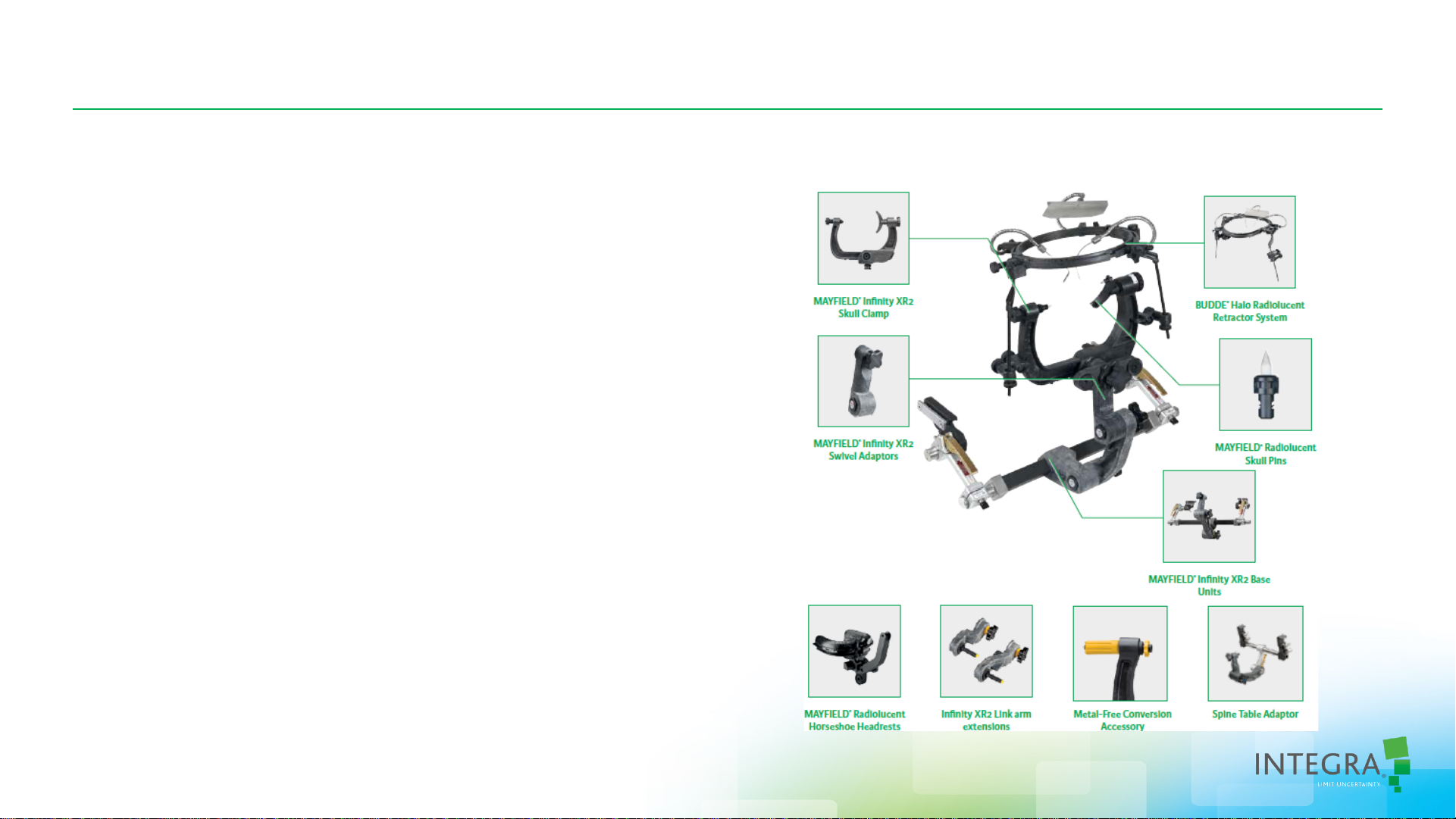
MAYFIELD®Imaging Products
• Head Clamp, Base Unit and Accessories
• Metal Free Conversion Accessory
• Link Arm Extensions
• Tri-Star Swivel Adapter
• Radiolucent Horseshoe Headrest
• Spine Table Adapter (Jackson Table)
• Radiolucent Skull Pins
• Titanium
• Sapphire
• Radiolucent Budde®Halo System (this system
is outside the scope of this training)
MAYFIELD is a registered trademark of SM USA Inc. and is used by Integra under license.
Budde is a registered trademark of Integra LifeSciences Corporation in the United States and/or other countries.
0688771-10688771-1
Page 3

MAYFIELD Imaging: Head Clamp
• Clamp:
• Made of carbon-filled PEEK
• Little or no artifact
• Only metal is the spring in the torque knob
• Metal-free conversion accessory offers a
completely metal free set-up (different torque
knob)
Head Clamp (Standard
Configuration)
Metal Free Conversion
Accessory
0688771-10688771-1
Page 4

MAYFIELD Imaging: Head Clamp
• Standard Clamp
1. XR2 Standard Torque Screw (439A1095)
2. XR2 Adult Rocker (439A1094)
3. Swivel Lock Knob
4. Skull Clamp Base or Body
5. Plunger
6. Starburst Attachment
7. Skull Clamp Ratchet Extension
• Accessories
a. XR2 Force Applicator, 439A1093 (included with
metal free conversion kit, 439A1092)
b. Stop Wheel
1
Head Clamp (Standard
Configuration)
Metal Free Conversion
Accessory
a
2
7
6
5
b
c
4
3
c. Metal free ratchet extension
d. XR2 Child’s Rocker (439A1091)
d
0688771-10688771-1
Page 5
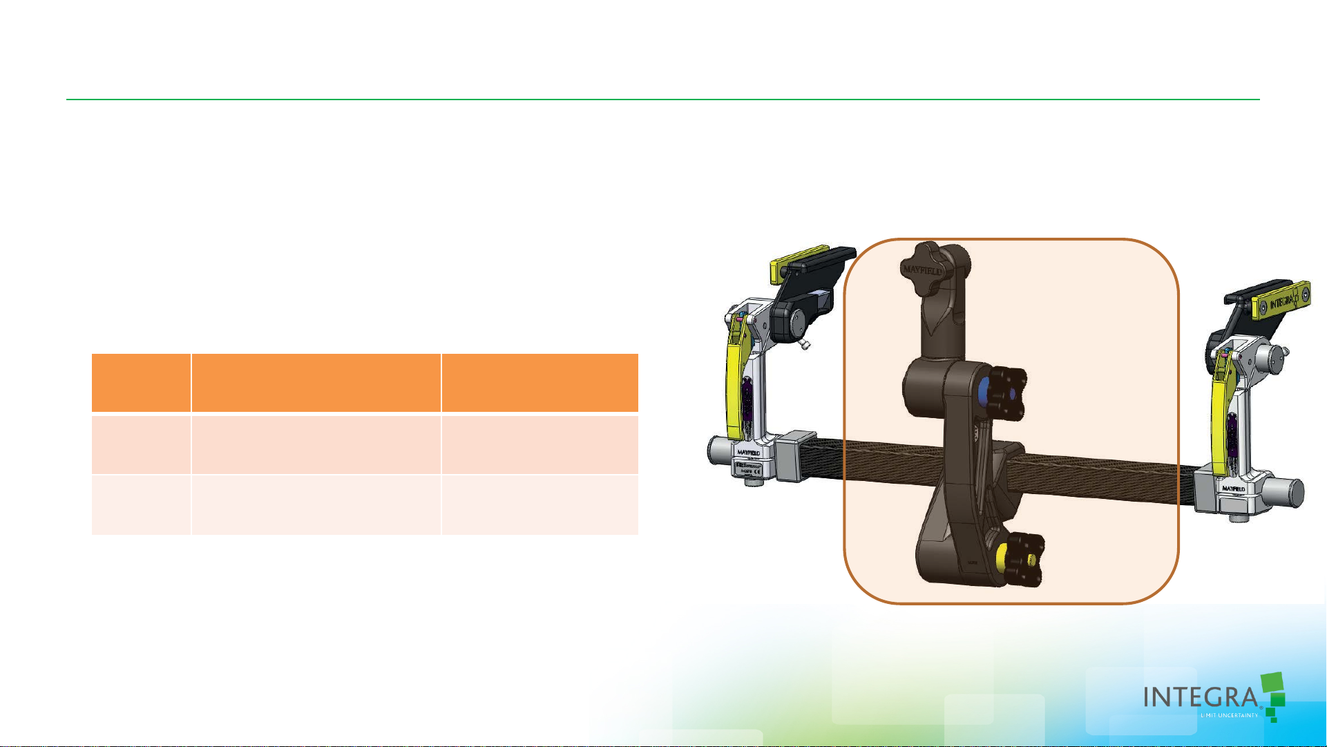
MAYFIELD Imaging: Base Unit
• Base Unit:
• Metal free zone around the head clamp
attachment / scanning area
• Width adjustable – 2 different sizes
Item
No.
A2079 19.5in to 24in
A2079E 22in to 28in
OR Table Width(s)
(Side rail to side rail)
(49.6 cm to 61 cm)
(55.9 cm to 71.1 cm)
Base Unit
Metal free zone
Cross Bar Width
Approx. 28”
Approx. 32”
0688771-10688771-1
Page 6
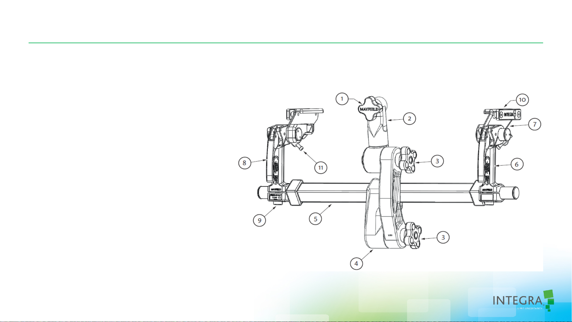
MAYFIELD Imaging: Base Unit
• Identification:
1. Skull Clamp/Headrest Locking Knob
2. Swivel Adaptor
3. Link Arm Locking Knobs
4. Yoke
5. Crossbar
6. Base Handle
7. Side Rail Bracket
8. Locking Lever
9. Base Handle Adjustment Knob
10.Auxiliary Side Rail
11.Side Rail Bracket Locking
Base Unit
0688771-10688771-1
Page 7
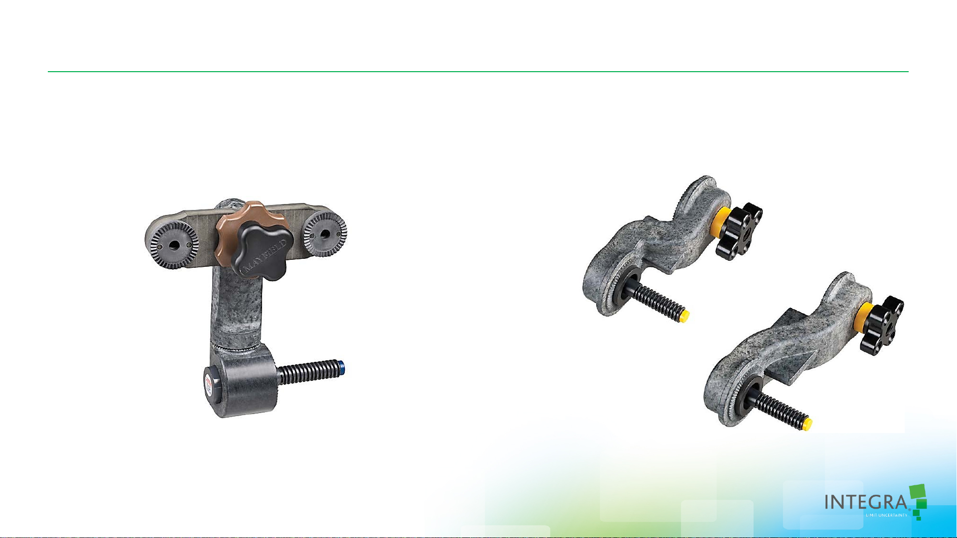
MAYFIELD Imaging: Base Unit Accessories
• Tri-Star Swivel Adapter , A21 1 1 • Extension Arms
437A2224, 5 inch
437A2225, 7 inch
0688771-10688771-1
Page 8

MAYFIELD Imaging: Horseshoe Headrests
Pediatric Horseshoe Headrest, A2011
Adult Horseshoe Headrest, A2010
Starburst to attach to standard swivel or tri-star swivel adapter
0688771-10688771-1
Page 9

MAYFIELD Imaging: Horseshoe Headrests
Spine Table Adapter, A2600R
Metal
free zone
Using the Spine Table Adapter with the
Jackson Table
0688771-10688771-1
Page 10

MAYFIELD Imaging
Radiolucent Products (XR2)
Instructions for Use Refresher
10
0688771-10688771-1
Page 11

MAYFIELD Imaging Base Unit
Review of Components
Rail end bracket
Locking Handle
with Locking
Lever
Tri-Star Swivel Adaptor (Blue ring)
(Available as an Accessory )
Link Arm
(Yellow ring)
Std. Swivel Adaptor (Blue ring)
Side Rail
Base Handle
Adjustment
Knob
0688771-10688771-1
Page 12

Refresher on Instructions for Use
Step 1. With the rail end brac ket toggle locks loosened a nd t he loc k in g handles unlocked, hold t he
base unit as shown for attachment to t he OR Table; grasp the side rails on the end brackets with
each hand.
Second
Locking handles
are unlocked &
opening “up”
First
Rail end bracket toggle
locks are loosened to
allow easy attachment
to the table side rails
Safety Latch
0688771-10688771-1
Page 13

Refresher on Instructions for Use
Step 2. Slide the base unit brackets onto the side rails of the operating room table.
Note that locking handles
are opening “up” and NOT
DOWN
0688771-10688771-1
Page 14

Refresher on Instructions for Use
Step 3. Secure the brackets to the side rails.
Turning rail end bracket
toggle locks
Tighten sec urely to
side rails
Cautions:
Keep finger clear of hinge points when
closing the base unit locking levers. It is
recommended that the levers be closed
using the palm of the hand.
Always be sure the locking mechanisms
are secure after completing table
adjustments. Verify that the locking
lever is secure by confirming that the
safety latch is engaged.
0688771-10688771-1
Page 15

Refresher on Instructions for Use
Step 4. At taching the Link and Adaptor to the Base Unit A ssembly.
Note the color-coded sleeves – Line them up,
yellow-to-yellow & blue-to-blue
0688771-10688771-1
Page 16

Refresher on Instructions for Use
Step 5. Positioned to await attachment of the skull clamp.
Locking handles are unlocked
Link and swivel adaptor ar e
connected but not tightene d
for easy movement and
attachment to the skull clamp
Note: The head section of the
OR table can be attached
prior to the patient entering
the OR.
0688771-10688771-1
Page 17

Refresher on Instructions for Use
Step 6. With the skull clamp attache d to the pat ient and in position, the Adaptor is brought up for
attachment to the skull clamp
Locking Handle
Swivel/Clamp
Torque Knob
Link/Swivel
Torque Knob
Attach in this order
1. Attach swivel adaptor to skull clamp
2. Lock both locking handles
(Use an “Open-Palm” to close handles.
Make certain that the locking levers are
engaged)
3. Tighten Swivel Adaptor knob (Blue)
4. Tighten Link attachment (Yellow)
5. Double-check all connections for
being tight and secure (double-check
does not mean double-tighten)
Link torque knob
0688771-10688771-1
Page 18

Refresher on Instructions for Use
Step 7. With the system now locked and ready, confirm that all knobs and levers are locked and
secure.
0688771-10688771-1
Page 19

Refresher on Instructions for Use
Step 8. Knobs should not be overtightened. Over-tightening the mechanisms’ adjustment screws
may result in damage to the unit.
Please remember that overextending or overloading the base unit may result in unintended
move m e nt , shortene d product life and/or dama ge to the unit
0688771-10688771-1
Page 20

Always Remember The Indications for Use, Warnings and Cautions
0688771-10688771-1
Page 21

Questions?
0688771-10688771-1
Page 22

Thank you
0688771-10688771-1
 Loading...