

Page 1
EN – ENGLISH .......................................................................................................
FR – FRANÇAIS ......................................................................................................
IT – ITALIANO ........................................................................................................
DE – DEUTSCH .....................................................................................................
ES – ESPAÑOL .......................................................................................................
NL – NEDERLANDS ..............................................................................................
Integra®
Brain Retractor System
( A2012)
Instruction Manual
Distributed by:
Integra LifeSciences Corporation
4900 Charlemar Drive, Building A
Cincinnati, OH 45227, USA
Tel: 513-533-7979
Fax: 513-271-1915
integralife.com
Manufacturer:
Mediflex Surgical Products
250 Gibbs Road
Islandia, NY 11749 USA
Integra LifeSciences Services France
Immeuble Séquloa 2, 97 allée Alexandre Borodine
Parc Technologique de la Porte des Alpes
69800 Saint Priest - France
+33(0) 437 47 59 1
0086
Page 2

This page is intentionally le blank
Page 3
3
Integra
Brain Retractor System
( A2012)
Instruction Manual
Distributed by:
Integra LifeSciences Corporation
4900 Charlemar Drive, Building A
Cincinnati, OH 45227, USA
Tel: 513-533-7979
Fax: 513-271-1915
integralife.com
Manufacturer:
Mediflex Surgical Products
250 Gibbs Road
Islandia, NY 11749 USA
Integra LifeSciences Services France
Immeuble Séquloa 2, 97 allée Alexandre Borodine
Parc Technologique de la Porte des Alpes
69800 Saint Priest - France
+33(0) 437 47 59 1
0086
EN – English
Page 4

4
EN – ENGLISH
Meaning Of Symbols Used In This Manual - ENGLISH
CAUTION!
Hazards which could result in equipment or property damage
WARNING!
Hazards which could result in severe personal injury or death
Caution
Product complies with the requirements of directive 93/42/EEC
Manufacturer
Authorized Representative in the European Community
Consult Instructions for Use
Caution: Federal (US) law restricts this device to sale by or on the
order of a licensed healthcare practitioner.
Catalog number
Date of manufacture (YYYY-MM-DD)
Lot number
Serial number
Page 5

5
EN – ENGLISH
ENGLISH
Indications for Use
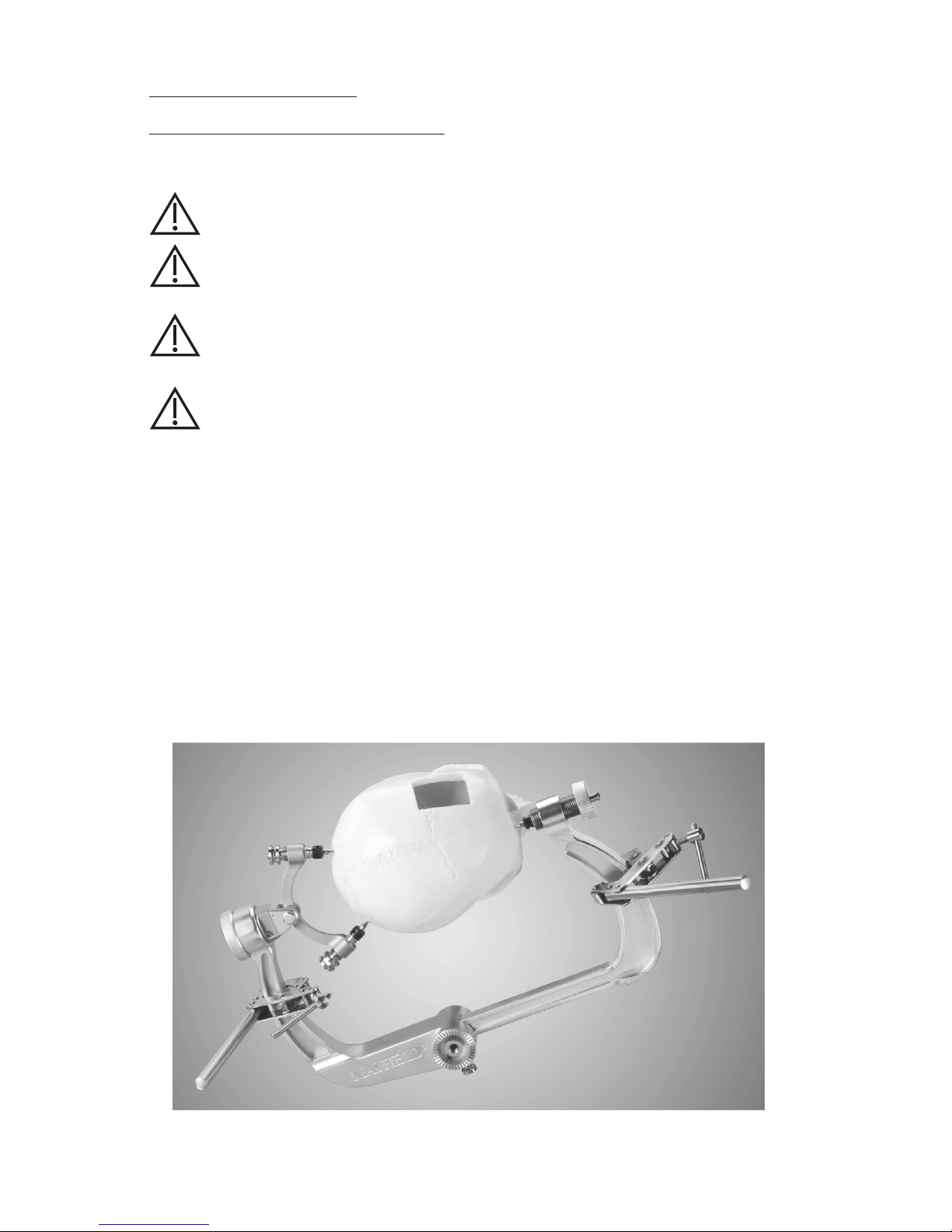
The Integra® Brain Retractor System is indicated for retraction of brain tissue during
neurosurgical procedures. The Integra Brain Retractor may be used in conjunction with
MAYFIELD® Skull Clamps (REF #A1013, A1014, A1059, A1108, A1114, and A2000) or may aach
to the side rails of the operating room table.
The Integra Brain Retractor System also serves to support and position various instruments
and handrests.
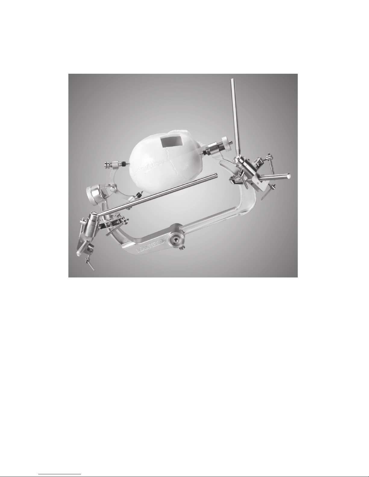
Description
The Integra Brain Retractor System is a set of components that allows the surgeon to
construct a framework surrounding the operative site for the purposes of retracting tissue
during neurosurgical procedures. Included are a pair of Primary Bars, with clamps that
aach to the skull clamp aer the sterile draping process. Longer Floating Secondary
Bars are then clamped to either the Primary Bars or to each other. Retractor Arms can
be aached to the Floating Secondary Bars and serve to support and position various
instruments, including the Retractor Blades of the Integra Brain Retractor System.
Suctioning devices, dissectors, scissors, drills, and handrests can also be aached.
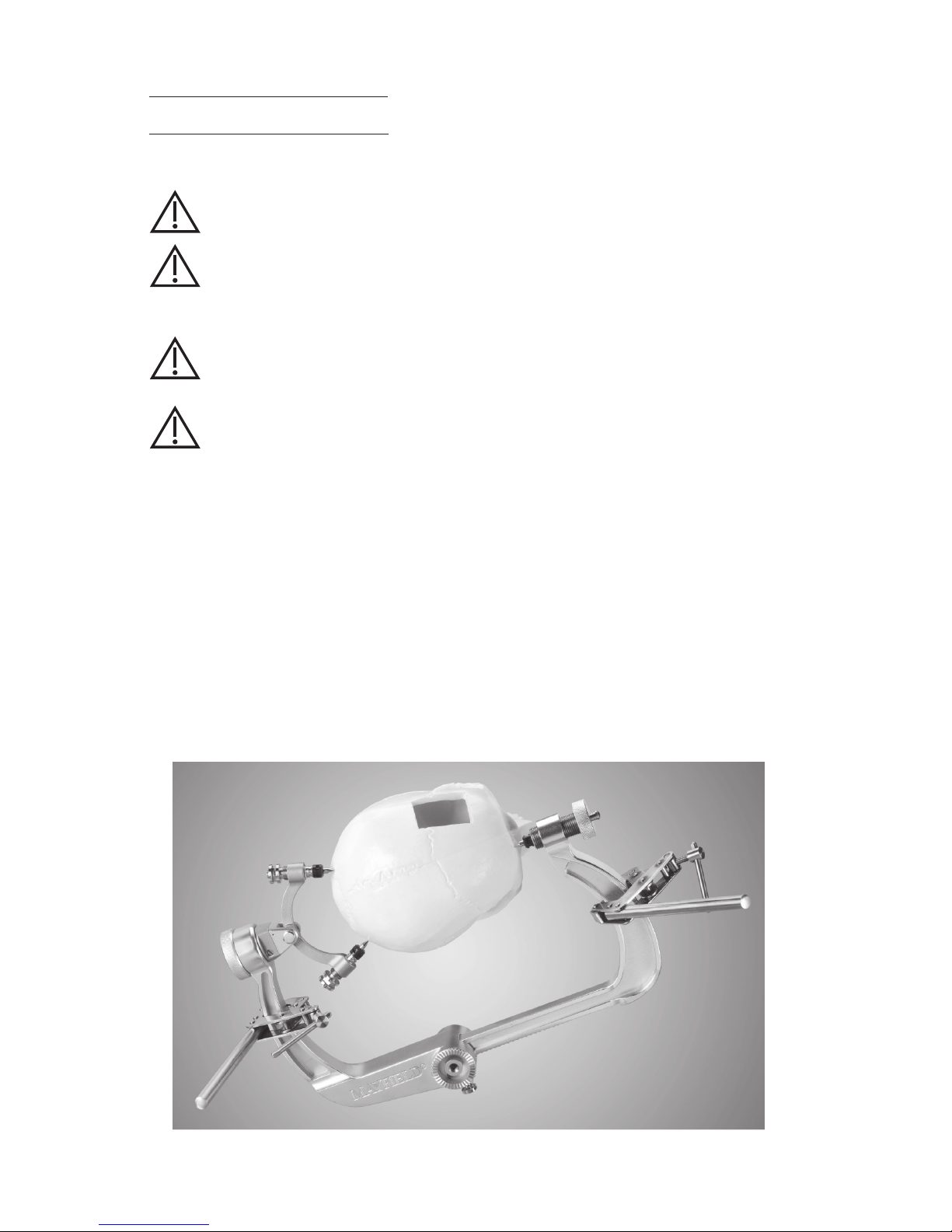
System Components
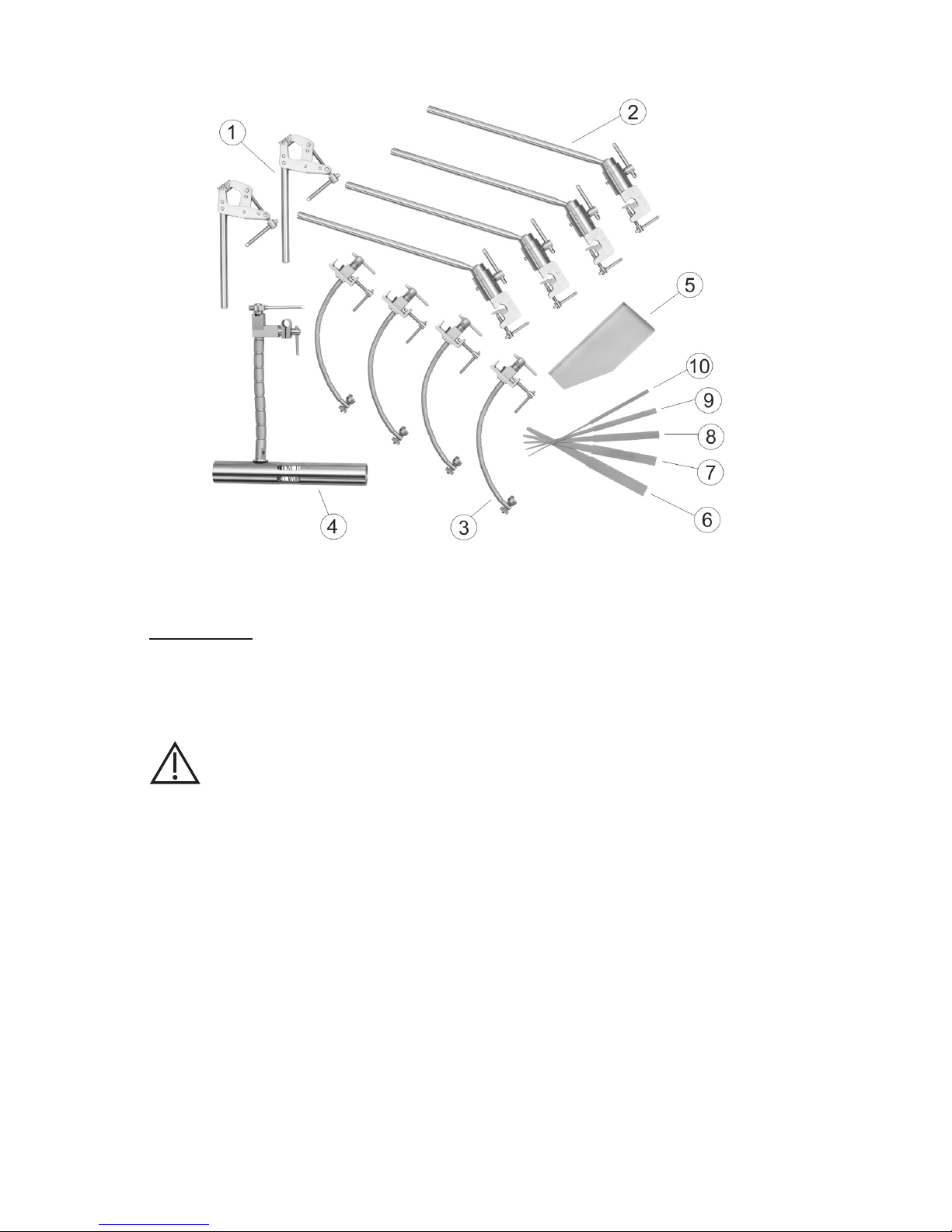
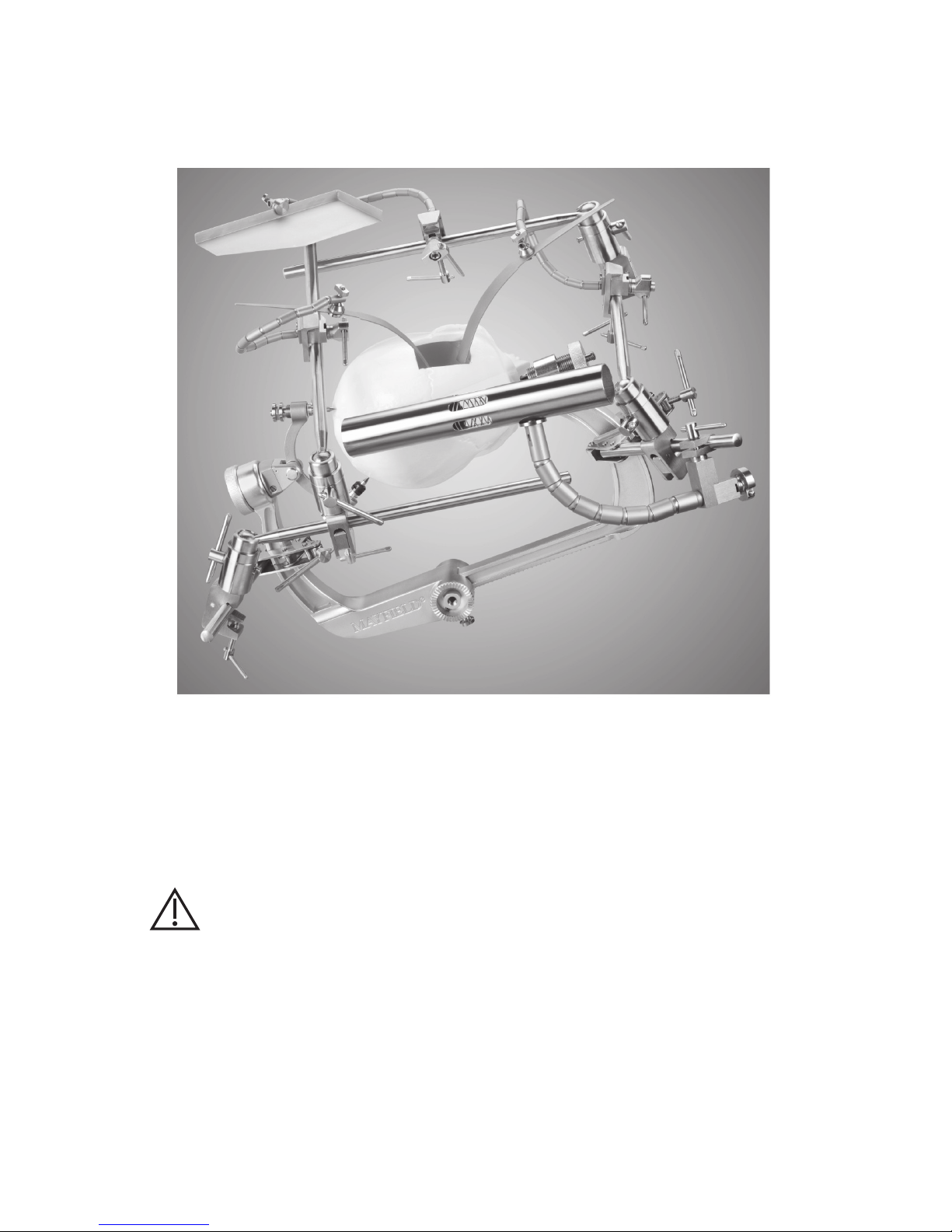
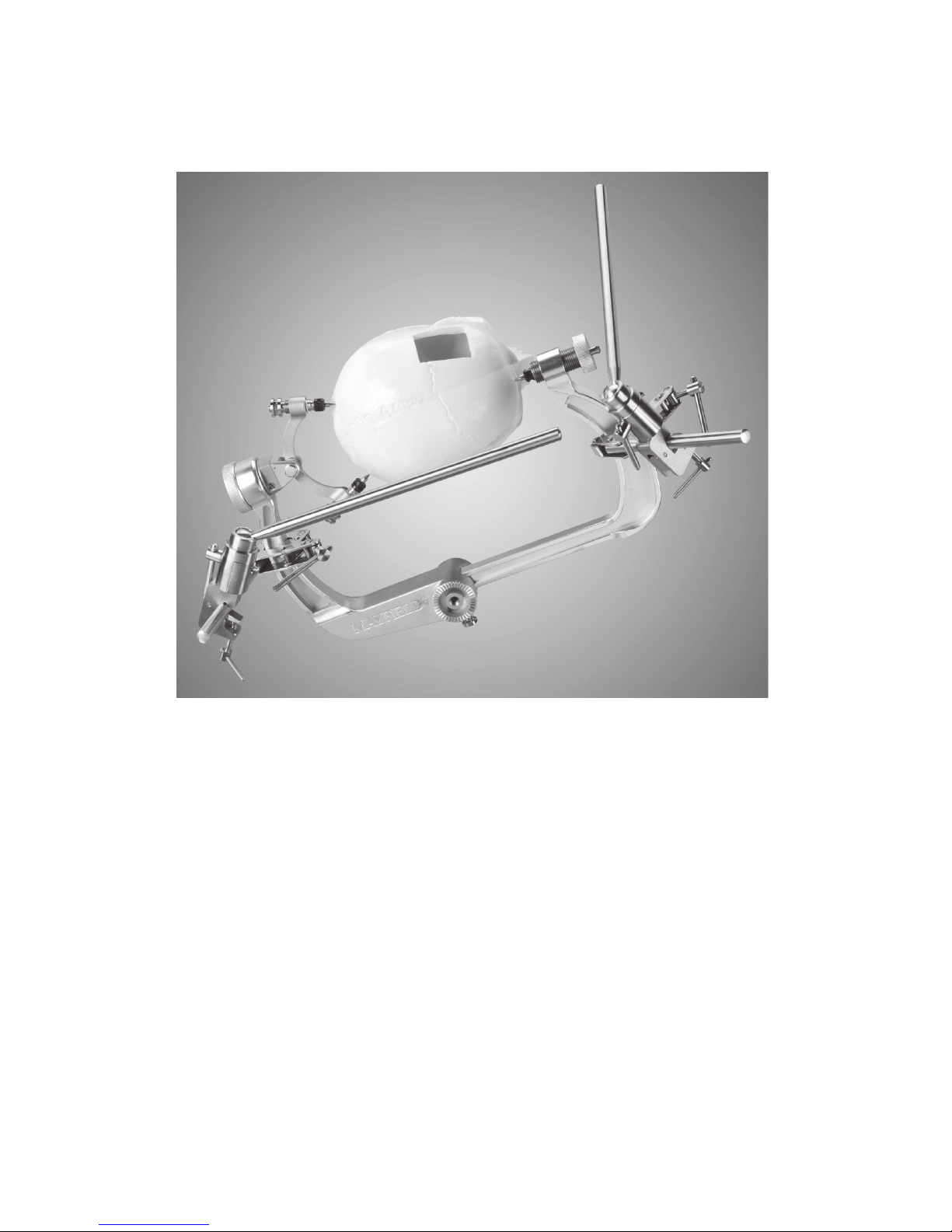
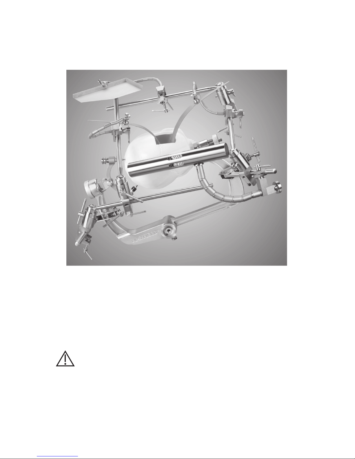
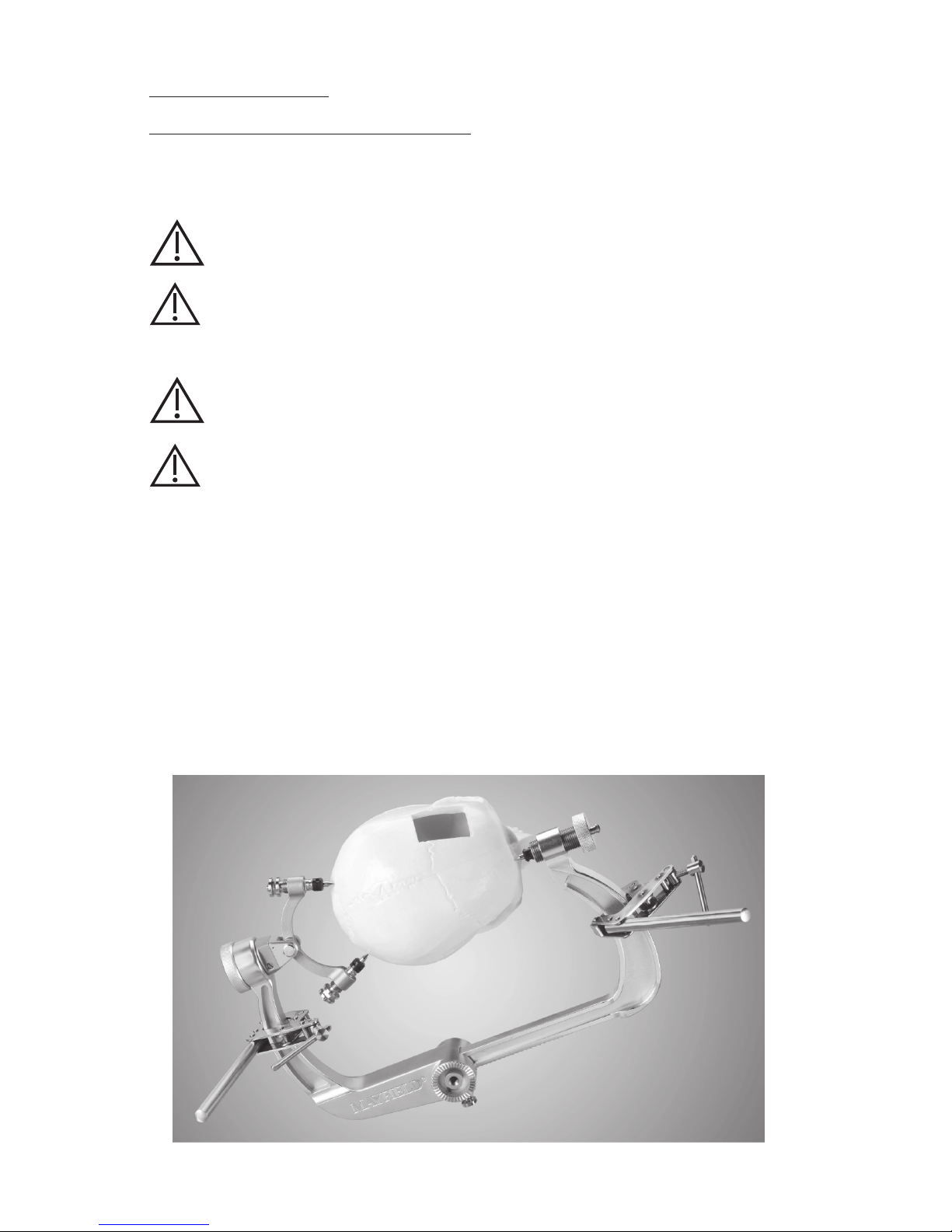
The Integra Brain Retractor System includes the following components (Figure 1):
1. Primary Bars (quantity 2)
2. Floating Secondary Bars (quantity 4)
3. Retractor Arms (quantity 4)
4. Handrest
5. Paie Tray
6. Tapered Retractor Blade, 1/4” to 3/4” (6.4 mm to 19.1 mm)
7. Tapered Retractor Blade, 5/32” to 5/8” (4.0 mm to 15.9 mm)
8. Tapered Retractor Blade, 1/8” to 1/2” (3.2 mm to 12.7 mm)
9. Tapered Retractor Blade, 3/32” to 3/8” (2.4 mm to 9.5 mm)
10. Tapered Retractor Blade, 1/16” to 1/4” (1.6 mm to 6.4 mm)
11. Sterilization Case (not shown)
Page 6
6
EN – ENGLISH
Figure 1
Inspection
Always inspect components of the Integra Brain Retractor System before and aer each use.
If a component appears damaged and/or does not seem to function properly, immediately
send the device to Integra LifeSciences, Cincinnati, Ohio, for evaluation and repair or
replacement (see Service and Repair section).
WARNING:
Device must not be used if it appears to be damaged or functioning incorrectly.
Doing so may result in serious patient injury.
Page 7
7
EN – ENGLISH
Instructions for Use
Aachment to MAYFIELD Skull Clamp
The following assembly instructions are for aachment of the Integra Brain Retractor
System to a MAYFIELD Skull Clamp (REF A1013, A1014, A1059, A1108, A1114, or A2000).
WARNING:
Device is supplied non-sterile and requires sterilization prior to each use.
WARNING: Failure to read and follow instructions furnished in this product insert
may result in skull pin slippage and serious patient injury, such as scalp lacerations,
skull fracture, or even death.
CAUTION:
The patient should be positioned in the MAYFIELD Skull Clamp and draped in the
usual manner.
WARNING: Failure to properly position patient and to fully tighten and secure all
adjustable portions of this or any similar device may result in skull pin slippage and
serious patient injury, such as scalp laceration, skull fracture, or even death.
From this point, the field is sterile. The entire assembly process shown is to be carried out
using sterile technique.
1. Prior to each use, clean and sterilize all system components as described in Cleaning and
Sterilization sections.
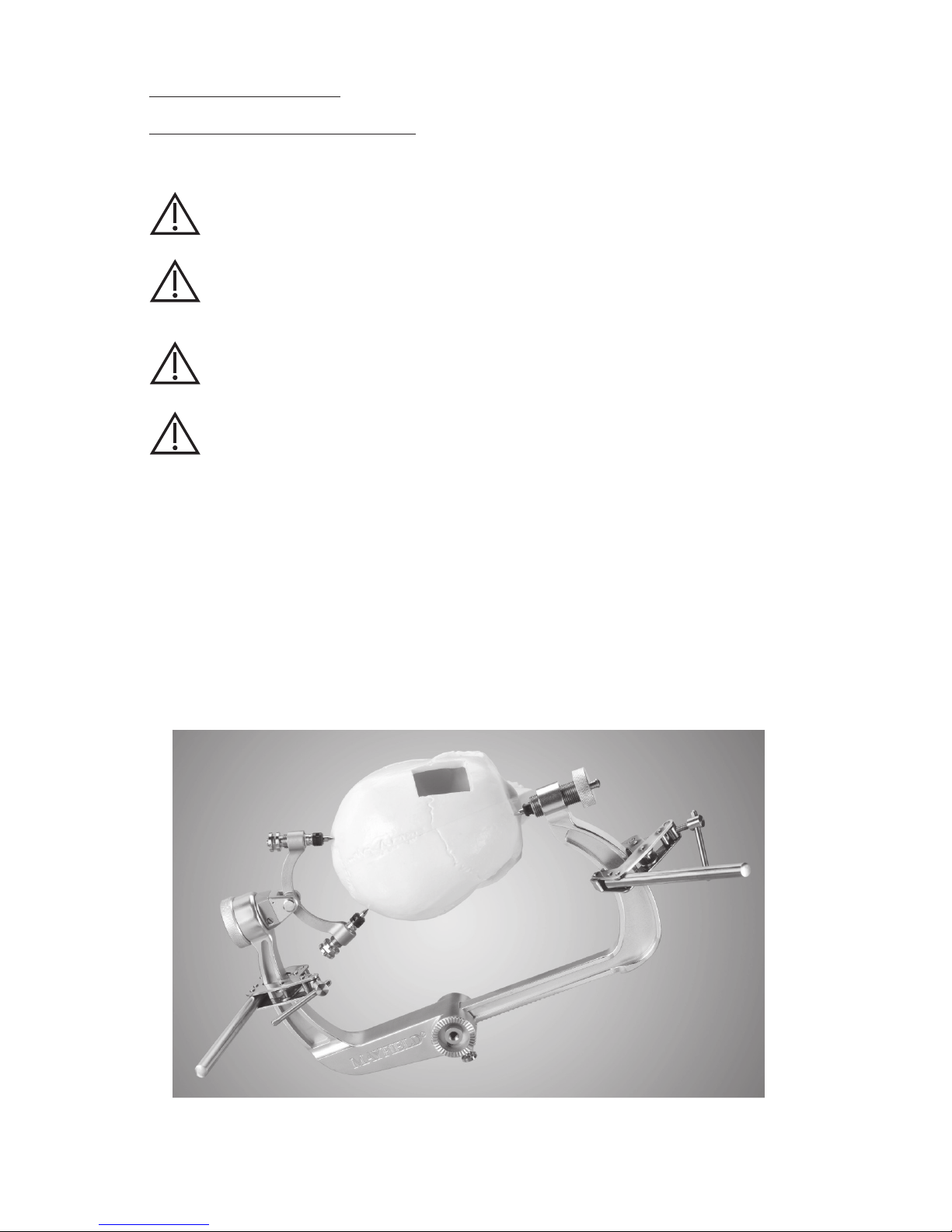
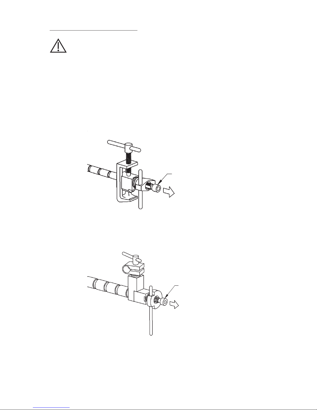
2. Locate the MAYFIELD Skull Clamp under the sterile surgical drape. Aach the Primary
Bars over the sterile drape around the vertical uprights of the skull clamp. The Primary
Bars are used to aach the Floating Secondary Bars for mounting the Retractor Arms and
Handrest. Tighten each Primary Bar clamp until there is no movement of the Primary Bar
clamp on the skull clamp upright (Figure 2).
Figure 2
Page 8

8
EN – ENGLISH
3. Aach a Floating Secondary Bar to each of the Primary Bars. Tighten each Floating
Secondary Bar until there is no movement on the Primary Bars (Figure 3).
Figure 3
The universal joint of the Floating Secondary Bars facilitates positioning of the bar for
mounting the Retractor Arms and other tools.
Page 9
9
EN – ENGLISH
4. The Retractor Arms and the Handrest can be aached to either a Primary Bar or a Floating
Secondary Bar. Position the Retractor Arm or the Handrest where it is needed and tighten
the clamp until there is no movement (Figure 4).
Figure 4
Once the Retractor Arm or the Handrest is in position, tighten the tension-seing knob
to hold it in position. For adjustments to the Retractor Arm or the Handrest, loosen the
tension-seing knob first before moving and then re-tighten.
The Paie Tray and Retractor Blades are aached to the ends of the Retractor Arms.
CAUTION:
Forcing the Retractor Arms or the Handrest to move against their tightened tension
may cause the cable in the arm to wear and possibly break. The ball joint segments
may become scored and the arm may tend to dri. Aer a period of time, driing may
be experienced even though the knob is tight. This is usually due to the drawbar threads
becoming worn, necessitating replacement of the part.
Page 10
10
EN – ENGLISH
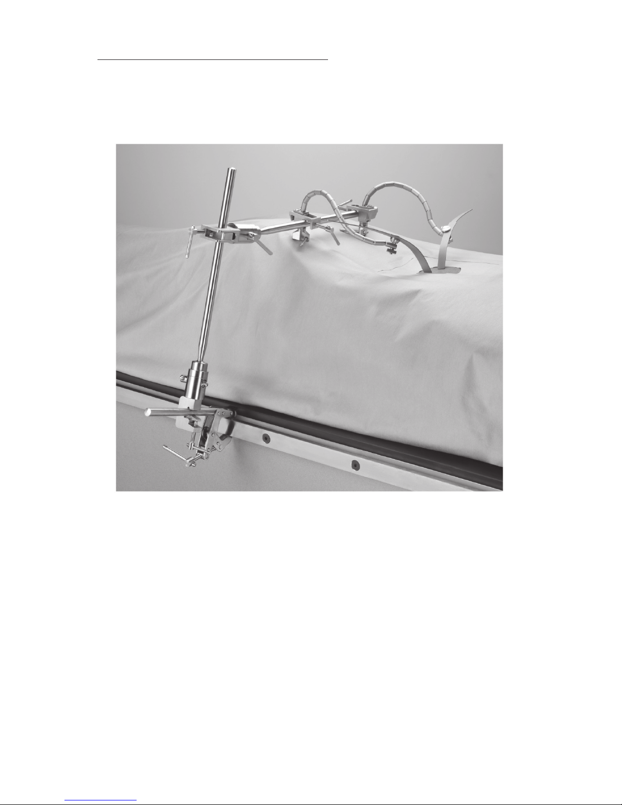
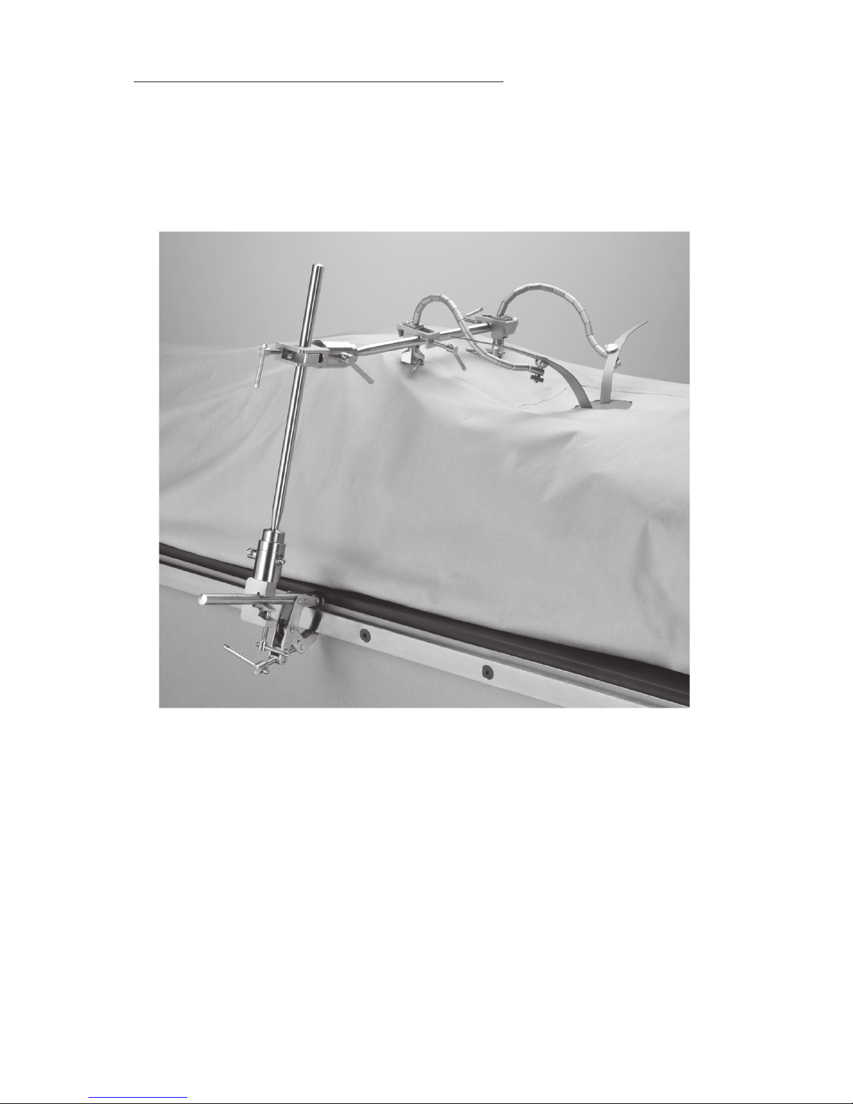
Aachment to Side Rails of Operating Room Table
Aach a Primary Bar to the side rail of the operating room table. Aach a Floating
Secondary Bar to the Primary Bar (Figure 5). Continue to set up the surgical field using both
the Floating Secondary Bars and the Primary Bars for aachment of the Retractor Arms,
Retractor Blades, and the Handrest as described above.
Figure 5
Page 11

11
EN – ENGLISH
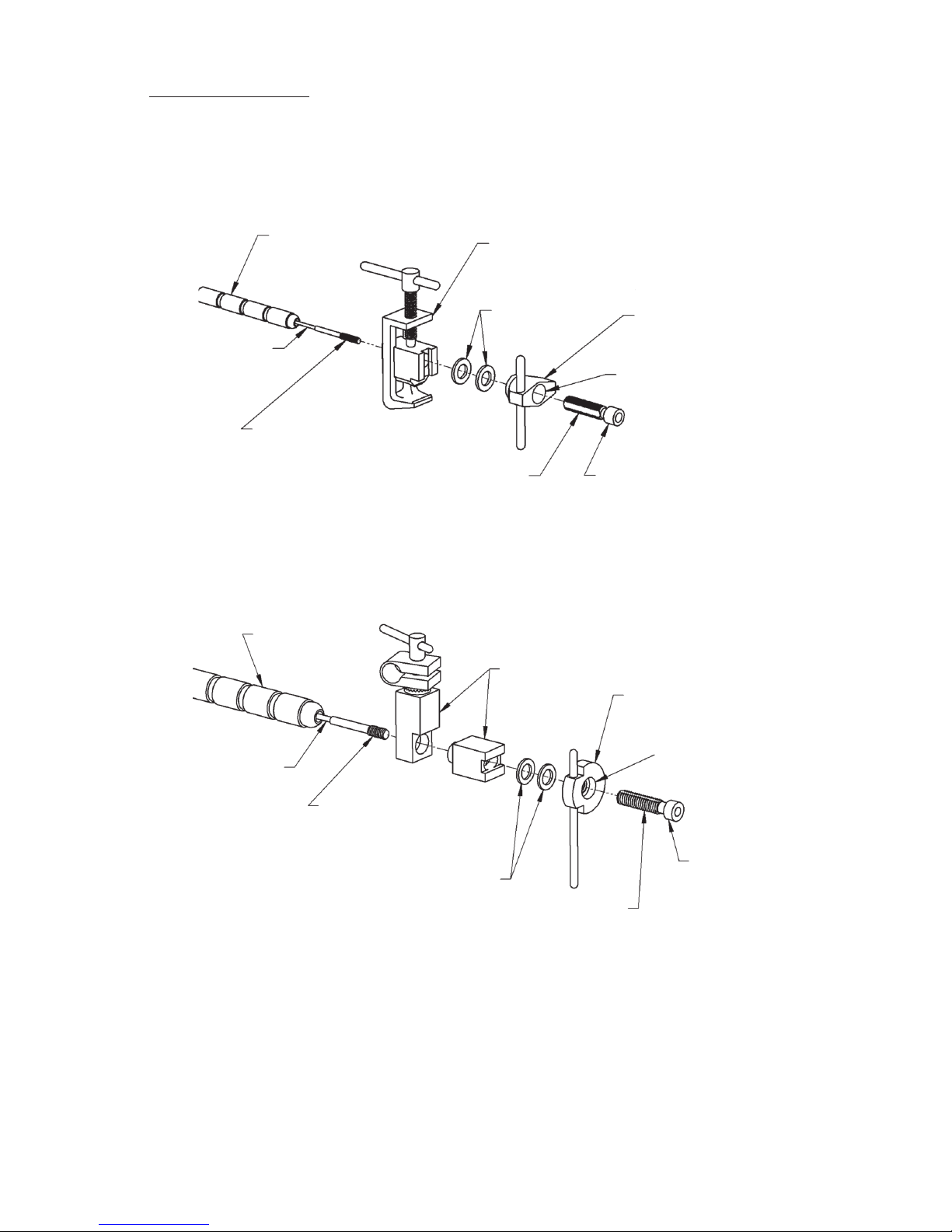
Care and Maintenance
The Retractor Arms and the Handrest consist of a series of ball joint segments that make
up the flexible arm, with holes through which a steel cable runs. Aached to the cable is a
swaged screw which is threaded into a drawbar (Figures 6 and 7).
CLAMP
ASSEMBLY
WASHERS
TENSION-
SETTING
KNOB
WELL
HUBDRAWBAR
SWAGED SCREW
THAT IS THREADED
INTO DRAWBAR
BALL JOINT
SEGMENTS
CABLE
Figure 6: Retractor Arm
CLAMP
ASSEMBLY
WASHERS
TENSION-
SETTING
KNOB
WELL
HUB
DRAWBAR
SWAGED SCREW
THAT IS THREADED
INTO DRAWBAR
BALL JOINT
SEGMENTS
CABLE
Figure 7: Handrest
Page 12
12
EN – ENGLISH
Reseing the Drawbar to Zero
WARNING:
Reset the drawbar to zero aer each use to help prevent driing of the flexible arms
and damage to the drawbar. Do not store or sterilize the Retractor Arms or the
Handrest while the cable is under tension.
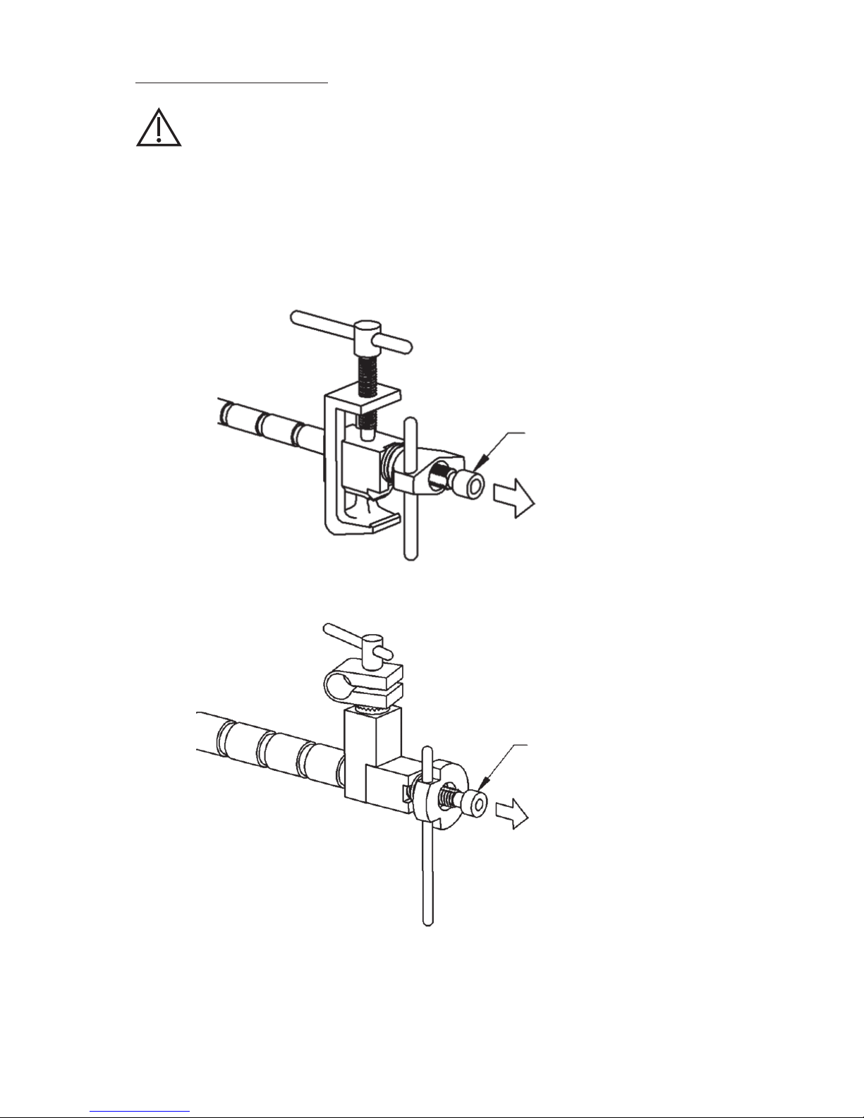
Each Retractor Arm and Handrest is received by the customer with the drawbar at zero
seing: the jointed arm has lile or no slack and the drawbar is totally recessed in the well
of the tension-seing knob. The flexible arm is stiffened during surgery by rotating the
tension-seing knob clockwise. The hub of the drawbar will protrude slightly as the cable
is pulled. Aer much use, the drawbar may begin to protrude excessively (Figures 8 and 9).
PROTRUDING
DRAWBAR
Figure 8: Retractor Arm
PROTRUDING
DRAWBAR
Figure 9: Handrest
Page 13
13
EN – ENGLISH
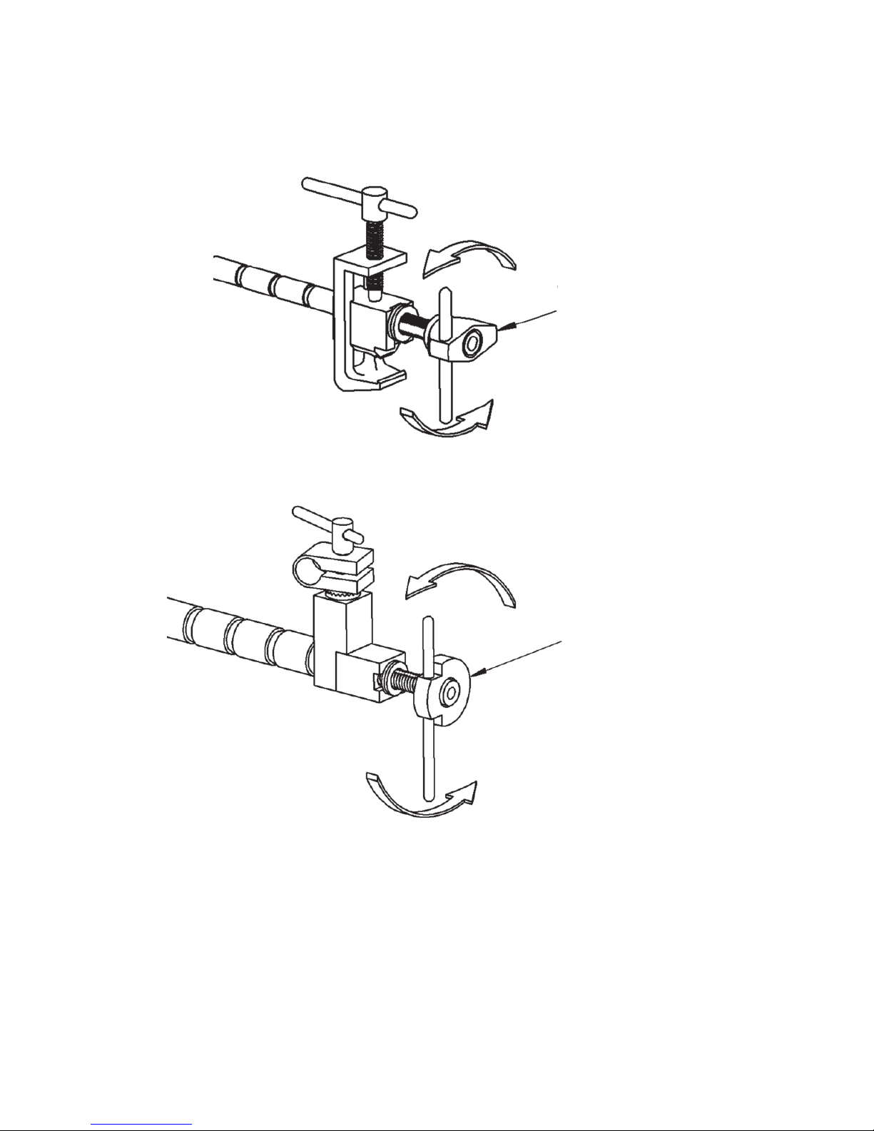
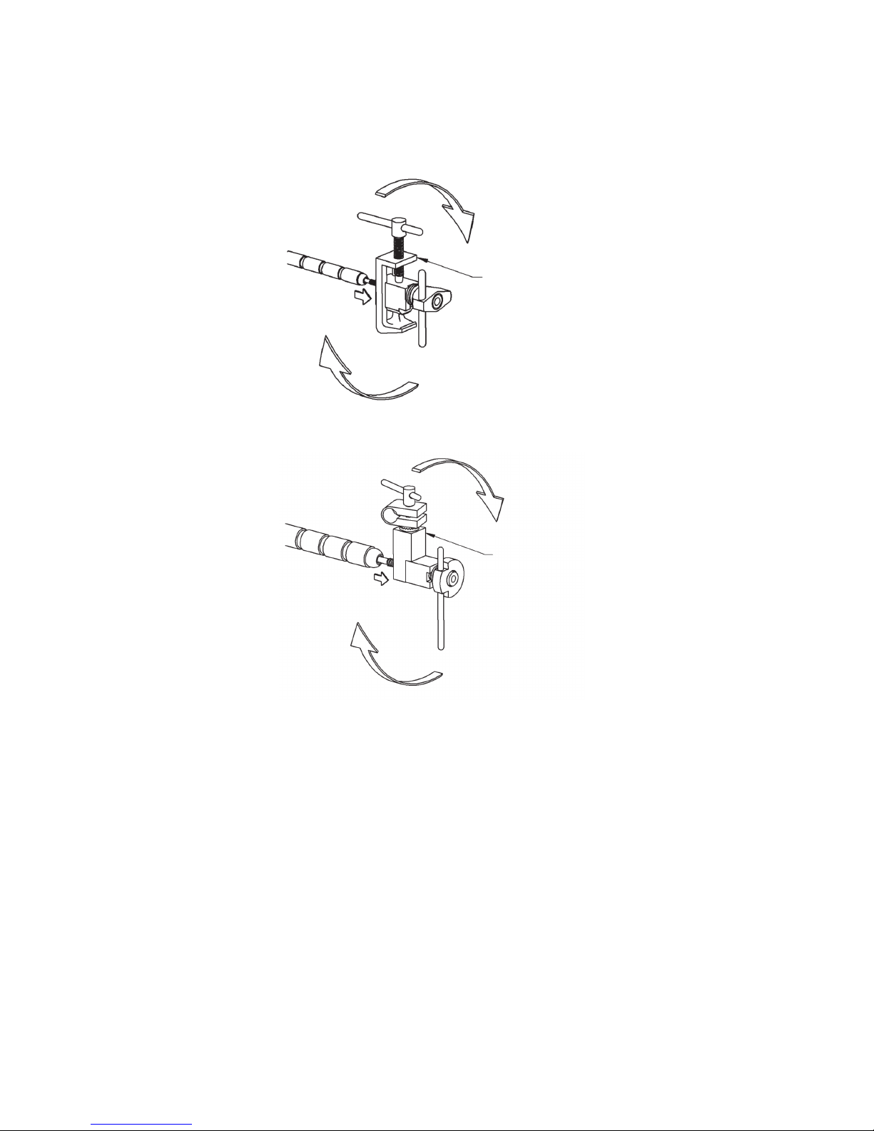
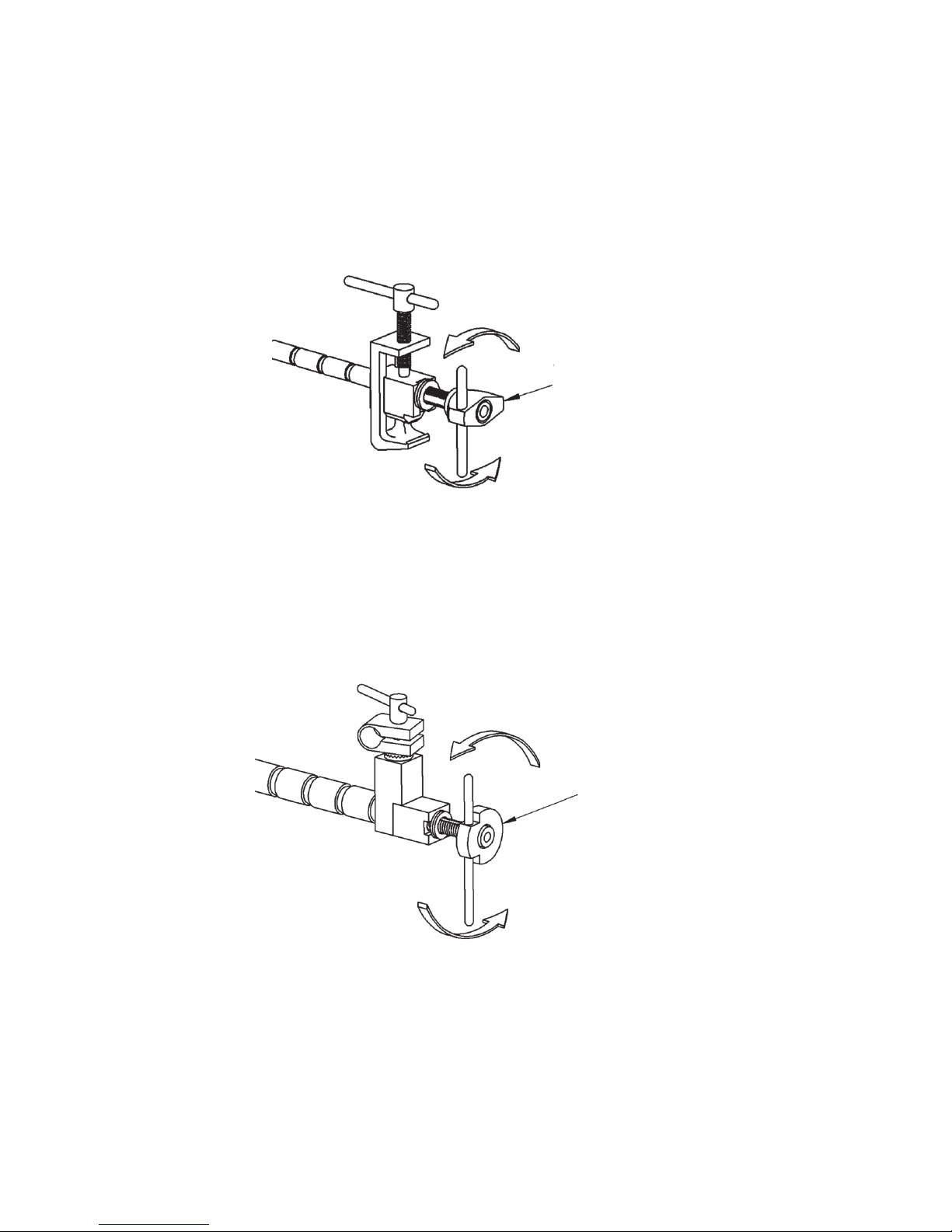
To relieve this condition, it is necessary to reset the drawbar to zero as follows:
1. Hold the flexible arm of the instrument in one hand, and with the other hand, spin the
tension-seing knob counterclockwise until it meets resistance (Figures 10 and 11).
TURN
TENSION-
SETTING
KNOB
Figure 10: Retractor Arm
TURN
TENSION-
SETTING
KNOB
Figure 11: Handrest
Page 14
14
EN – ENGLISH
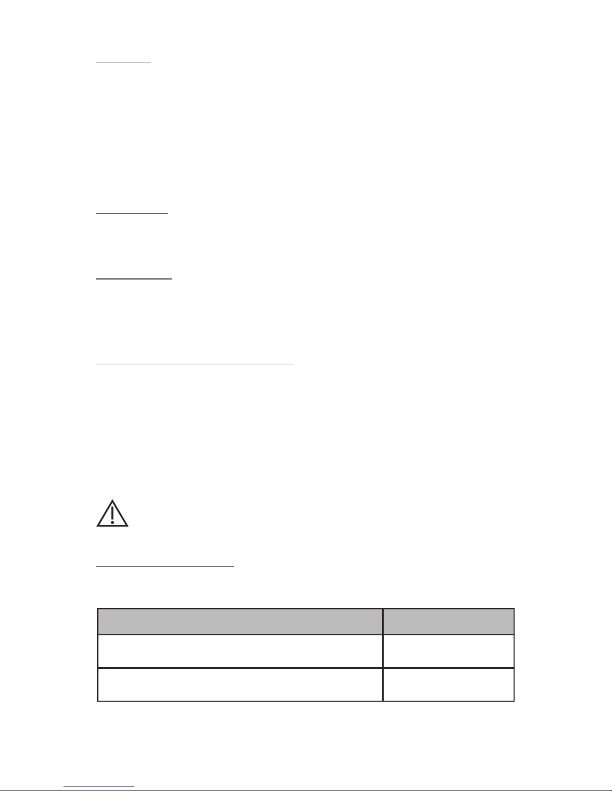
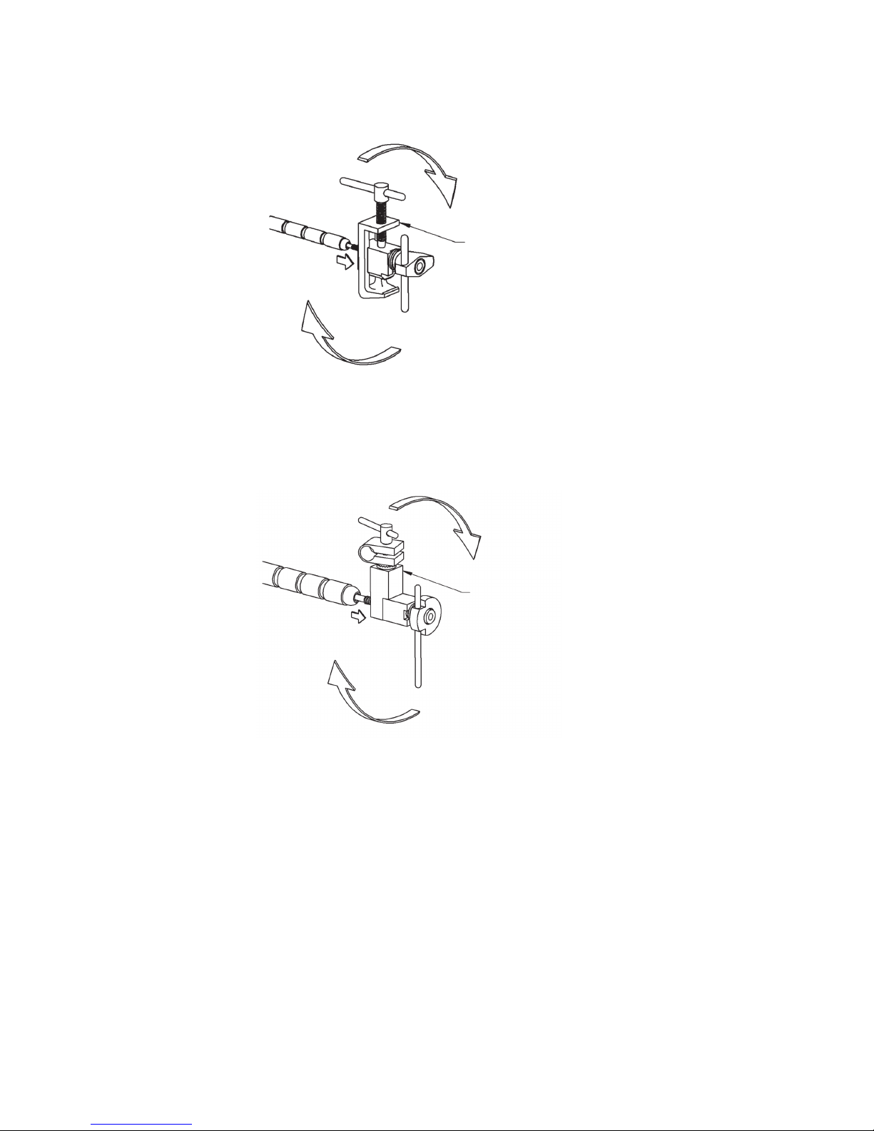
2. Hold the flexible arm in one hand, and with the other hand, spin the entire clamp
assembly clockwise. This will advance the threaded cable into the drawbar (Figures 12
and 13).
TURN
CLAMP
ASSEMBLY
Figure 12: Retractor Arm
TURN
CLAMP
ASSEMBLY
Figure 13: Handrest
Page 15
15
EN – ENGLISH
Cleaning
Prior to cleaning, disassemble the Integra Brain Retractor System into its components as
shown in Figure 1.
Do not disassemble the Retractor Arm assembly or the Handrest assembly. Loosen tension
on each instrument’s tension-seing knob, which will allow for ample separation of the
individual ball joint segments for appropriate cleaning.
Aer each procedure, use a so brush and mild detergent to remove all residual debris
from each instrument. It is recommended that the instruments and parts be ultrasonically
cleaned.
Lubrication
It is extremely important that movable parts be lubricated to keep these parts functional.
It is recommended that all components be immersed in a water-soluble lubricant prior to
sterilization.
Sterilization
Aer use, disassemble and clean the Integra Brain Retractor System as described above.
The Integra Brain Retractor System must be cleaned and sterilized prior to each use.
Steam sterilize the Integra Brain Retractor System according to the following validated
sterilization parameters.
Pre-Vacuum Steam Sterilization – Full Cycle:
Sterilization temperature: 132° C
Sterilization exposure time: 8 minutes
It is the user’s responsibility to validate any sterilization parameters which deviate from
those listed above.
Follow the sterilizer manufacturer’s instructions for operation and loading of steam
autoclave. There must be direct steam exposure to all surfaces of the instruments.
Allow components to cool to room temperature before use.
WARNING:
Do not sterilize the Retractor Arms or the Handrest while the cable is under tension.
Maintenance and Care
To ensure proper function and to extend the life and performance of the equipment, Integra
LifeSciences recommends the following:
Recommended Action Recommended Frequency
Return the device to the Integra LifeSciences Repairs
department for detailed inspection and servicing.
Once / year
Request that Integra NeuroSpecialists perform routine
inspections of the device
Twice / year
Page 16

16
EN – ENGLISH
In the absence of proper care and servicing of the device, negative effects may be seen aer
repeated processing over time which may lead to reduced performance.
Contact information: See the Service and Repair section for contact information on how to
return your device for periodic servicing and to request periodic inspections.
See Inspection and/or Service notes section for routine checks to be performed on the device.
Device Disposal
NOTE: Follow hospital procedures for disposal of this device.
Integra Standard Warranty
INTEGRA LIFESCIENCES CORPORATION (“INTEGRA”) warrants to the original purchaser only that each
new INTEGRA product is free from manufacturing defects in material and workmanship under normal
use and service for a period of one year (except as otherwise expressly provided as to accessory items)
from the date of delivery by INTEGRA to the first purchaser, but in no event beyond the expiration date
stated on any product labeling.
• Surgical instruments are guaranteed to be free from defects in material and workmanship when
maintained and cleaned properly and used normally for their intended purpose.
• Any covered product that is placed by INTEGRA under a lease, rental or installment purchase
agreement and that requires repair service during the term of such placement agreement shall be
repaired in accordance with the terms of such agreement.
If any covered defect occurs during the warranty period or term of such placement agreement, the
purchaser should communicate directly with INTEGRA’s home office. If purchaser seeks to invoke the
terms of this warranty, the product must be returned to INTEGRA at its home office. The defective
product should be returned promptly, properly packaged and postage prepaid. Loss or damage in return
shipment to INTEGRA shall be at CUSTOMER’s risk. INTEGRA’s sole responsibility under this warranty
shall be repair or replacement, at INTEGRA’s sole discretion at INTEGRA’s expense, subject to the terms
of this warranty and applicable agreements.
IN NO EVENT SHALL INTEGRA BE LIABLE FOR ANY INCIDENTAL, INDIRECT, CONSEQUENTIAL OR
PUNITIVE DAMAGES IN CONNECTION WITH THE ACQUISITION OR USE OF ANY INTEGRA PRODUCT.
Further, this warranty shall not apply to, and INTEGRA shall not be responsible for, any loss arising in
connection with the purchase or use of any INTEGRA product that has been repaired by anyone other
than an authorized INTEGRA service representative or altered in any way so as, in INTEGRA’s judgment,
to affect its stability or reliability, or which has been subject to misuse, negligence or accident, or
which has been used otherwise than in accordance with the instructions furnished by INTEGRA.
THIS LIMITED WARRANTY IS EXCLUSIVE AND IN LIEU OF ALL OTHER WARRANTIES, EXPRESSED
OR IMPLIED, AND OF ALL OTHER OBLIGATIONS OR LIABILITIES ON INTEGRA’S PART, AND INTEGRA
NEITHER ASSUMES NOR AUTHORIZES ANY REPRESENTATIVE OR OTHER PERSON TO ASSUME FOR IT
ANY OTHER LIABILITY IN CONNECTION WITH INTEGRA’S PRODUCTS.
INTEGRA DISCLAIMS ALL OTHER WARRANTIES, EXPRESSED OR IMPLIED INCLUDING ANY IMPLIED
WARRANTY OF MERCHANTABILITY OR OF FITNESS FOR A PARTICULAR PURPOSE OR APPLICATION
OR WARRANTY OF QUALITY AS WELL AS ANY EXPRESSED OR IMPLIED WARRANTY TO PATIENTS.
No warranty or guarantee may be created by any act or statement nor may this Standard Warranty be
modified in any way, except as a result of a writing signed by an officer of INTEGRA. These limitations
on the creation or modification of this warranty may not be waived or modified orally or by any
conduct.
Page 17

17
EN – ENGLISH
Service and Repair
For service and repairs outside the United States, contact your local authorized Integra representative.
Inside the United States, send all instruments for service or repair to:
Integra LifeSciences Corporation
4900 Charlemar Drive, Building A
Cincinnati, Ohio 45227
(Always include the purchase order number and a wrien description of the problem).
Or phone: 877-444-1114 (USA only) or 513-533-7979
Page 18

18
Manufacturer:
Mediflex Surgical Products
250 Gibbs Road
Islandia, NY 11749 USA
Integra LifeSciences Services France
Immeuble Séquloa 2, 97 allée Alexandre Borodine
Parc Technologique de la Porte des Alpes
69800 Saint Priest - France
+33(0) 437 47 59 1
Integra and the Integra logo are registered trademarks of Integra LifeSciences Corporation in the United
States and/or other countries. MAYFIELD is a registered trademark of SM USA, Inc. and is used by
Integra under license.
2018 Integra LifeSciences Corporation. All Rights Reserved. 451A2012 07/18 Rev. BA 0991735-1
Page 19
19
Système de Rétraction
Cérébrale Integra®
( A2012)
Mode d’emploi
Distribué par:
Integra LifeSciences Corporation
4900 Charlemar Drive, Building A
Cincinnati, OH 45227, États-Unis
Téléphone: 513-533-7979
Fax: 513-271-1915
integralife.com
Fabricant:
Mediflex Surgical Products
250 Gibbs Road
Islandia, NY 11749 États-Unis
Integra LifeSciences Services France
Immeuble Séquloa 2, 97 allée Alexandre Borodine
Parc Technologique de la Porte des Alpes
69800 Saint Priest — France
+33(0) 43 74 75 91
FR – Français
0086
Page 20

20
FR – FRANÇAIS
Aention
Ce produit est conforme aux exigences de la directive 93/42/CEE
Fabricant
Représentant autorisé dans la Communauté européenne
Consulter le mode d’emploi
Aention : Conformément à la loi fédérale américaine, ce
dispositif ne peut être vendu que par un professionnel de santé
agré ou sur ordonnance de ce dernier.
Référence catalogue
Date de fabrication (AAAA-MM-JJ)
Numéro de lot
N° de série
Signification des symboles utilisés dans ce manuel - FRANÇAIS
ATTENTION!
Dangers pouvant causer des dommages au matériel ou à aux biens
AVERTISSEMENT!
Dangers pouvant causer des blessures personnelles graves, voire fatales
Page 21

21
FR – FRANÇAIS
FRANÇAIS
Consignes d’utilisation
Le système de rétraction cérébrale Integra® est conçu pour la rétraction des tissus cérébraux
au cours des procédures neurochirurgicales. Il peut être utilisé en combinaison avec les
serre-crânes MAYFIELD® (réf. nº A1013, A1014, A1059, A1108, A1114 et A2000) ou fixé aux rails
latéraux de la table de la salle d’opération.
Le système de rétraction cérébrale Integra permet également de supporter et de positionner
divers instruments et appuis-main.
Description
Le système de rétraction cérébrale Integra est un ensemble de composants qui permet au
chirurgien de construire un cadre autour du champ opératoire afin de rétracter les tissus
au cours des procédures neurochirurgicales. Le système comprend une paire de barres
principales, avec des pinces qui se fixent sur le serre-crâne après le drapage stérile. Les
barres secondaires floantes, plus longues, sont ensuite fixées sur les barres principales
ou les unes sur les autres. Les bras de rétraction peuvent être fixés aux barres secondaires
floantes et permeent de supporter et de positionner divers instruments, y compris les
lames de rétraction du système de rétraction cérébrale Integra. Il est également possible d’y
fixer des appareils d’aspiration, des ciseaux, des forets et des appuis-main.
Composants du système
Le système de rétraction cérébrale Integra comprend les composants suivants (Figure 1) :
1. Barres principales (quantité : 2)
2. Barres secondaires floantes (quantité : 4)
3. Bras de rétraction (quantité : 4)
4. Appui-main
5. Plateau pour instruments
6. Lame de rétraction biseautée, de 6,4 à 19,1 mm (1/4 po à 3/4 po)
7. Lame de rétraction biseautée, de 4,0 à 15,9 mm (5/32 po à 5/8 po)
8. Lame de rétraction biseautée, de 3,2 à 12,7 mm (1/8 po à 1/2 po)
9. Lame de rétraction biseautée, de 2,4 à 9,5 mm (3/32 po à 3/8 po)
10. Lame de rétraction biseautée, de 1,6 à 6,4 mm (1/16 po à 1/4 po)
11. Étui de stérilisation (non illustré)
Page 22

22
FR – FRANÇAIS
Figure 1
Vérification
Vérifiez toujours les composants du système de rétraction cérébrale Integra avant
et après chaque utilisation. Si un élément semble endommagé et/ou semble ne pas
fonctionner correctement, envoyez immédiatement l’instrument à Integra LifeSciences,
Cincinnati, Ohio, États-Unis, où il sera évalué, réparé ou remplacé (voir la section Entretien
et réparation).
AVERTISSEMENT :
N’utilisez pas un instrument s’il semble endommagé ou s’il semble ne pas
fonctionner correctement. Le non-respect de cee consigne pourrait exposer le
patient à des risques de blessures graves.
Page 23
23
FR – FRANÇAIS
Instructions d’utilisation
Fixation au serre-crâne MAYFIELD
Les instructions de montage suivantes s’appliquent à la fixation du système de rétraction
cérébrale Integra sur un serre-crâne MAYFIELD (Réf. A1013, A1014, A1059, A1108, A1114 ou A2000).
AVERTISSEMENT :
L’instrument est livré non stérilisé ; il doit être stérilisé avant chaque utilisation.
AVERTISSEMENT : Le non-respect des instructions fournies dans cee notice
pourrait conduire à un glissement des broches crâniennes et pourrait exposer le
patient à des risques de blessures, telles que des lacérations du cuir chevelu, une
fracture du crâne, voire au décès.
ATTENTION :
Le patient doit être positionné dans le serre-crâne MAYFIELD et drapé selon la
procédure normale.
AVERTISSEMENT : Si le patient n’est pas correctement positionné et si toutes les
parties réglables de ce dispositif ou de tout dispositif similaire ne sont pas bien
fixées, la tige métallique permeant de maintenir le crâne pourrait glisser et le
patient pourrait subir de graves blessures, telles que des lacérations du cuir chevelu,
une fracture du crâne, voire le décès.
Dès lors, le champ opératoire est stérile. La procédure de montage illustrée doit être
intégralement effectuée au moyen d’une technique stérile.
1. Avant chaque utilisation, neoyez et stérilisez tous les composants du système comme
indiqué dans les sections Neoyage et Stérilisation.
2. Placez le serre-crâne MAYFIELD sous le drap chirurgical stérile. Fixez les barres principales
par-dessus le drap stérile autour des montants verticaux du serre-crâne. Les barres
principales servent à fixer les barres secondaires floantes qui permeent de monter les
bras de rétraction et l’appui-main. Serrez chaque pince des barres principales jusqu’à son
immobilisation sur le montant du serre-crâne (Figure 2).
Figure 2
Page 24
24
FR – FRANÇAIS
3. Fixez une barre secondaire floante sur chaque barre principale. Serrez chaque barre
secondaire floante jusqu’à son immobilisation sur les barres principales (Figure 3).
Figure 3
Le joint universel des barres secondaires floantes facilite le positionnement de la barre lors
du montage des bras de rétraction et d’autres outils.
Page 25
25
FR – FRANÇAIS
4. Les bras de rétraction et l’appui-main peuvent être fixés sur une barre principale ou
sur une barre secondaire floante. Positionnez le bras de rétraction ou l’appui-main à
l’endroit souhaité et serrez la pince à fond jusqu’à ce qu’elle soit immobilisée (Figure 4).
Figure 4
Une fois que le bras de rétraction ou l’appui-main est en position, vissez la molee de
réglage pour le maintenir en place. Pour régler la position du bras de rétraction ou de
l’appui-main, desserrez la molee de réglage avant de déplacer l’instrument. Revissez-la
ensuite.
Le plateau pour instruments et les lames de rétraction sont fixés aux extrémités des bras de
rétraction.
ATTENTION :
Si vous exercez une pression sur les bras de rétraction ou l’appui-main dans le sens
inverse de leur fixation, cela peut entraîner l’usure et/ou éventuellement la rupture
du câble présent dans le bras. Les segments de la rotule pourraient être entaillés et entraîner
la dérivation du bras. Au bout d’un certain temps, il se peut que le bras dérive même
lorsque la molee est serrée. Cela est généralement dû à l’usure des filetages de la barre de
traction ; il faut alors remplacer la pièce.
Page 26
26
FR – FRANÇAIS
Fixation aux rails latéraux de la table de la salle d’opération
Fixez une barre principale sur le rail latéral de la table de la salle d’opération. Fixez une
barre secondaire floante sur la barre principale (Figure 5). Continuez à installer le champ
opératoire en utilisant les barres secondaires floantes et les barres principales qui
permeent de fixer les bras de rétraction, les lames de rétraction et l’appui-main, comme
décrit ci-dessus.
Figure 5
Page 27
27
FR – FRANÇAIS
Entretien et soin
Les bras de rétraction et l’appui-main comprennent une série de segments à rotule qui
constituent le bras flexible, avec des trous pour acheminer un câble en acier. Une vis
matricée est fixée au câble ; elle est filetée dans une barre de traction (Figures 6 et 7).
ENSEMBLE
DE PINCES
RONDELLES
MOLETTE DE
RÉGLAGE
GORGE
MOYEU
BARRE DE
TRACTION
VIS MATRICÉE FILETÉE
DANS LA BARRE
DE TRACTION
SEGMENTS
À ROTULE
CÂBLE
Figure 6: Bras de rétraction
ENSEMBLE
DE PINCES
RONDELLES
MOLETTE DE
RÉGLAGE
GORGE
MOYEU
BARRE DE TRACTION
VIS MATRICÉE FILETÉE
DANS LA BARRE
DE TRACTION
SEGMENTS
À ROTULE
CÂBLE
Figure 7: Appui-main
Page 28
28
FR – FRANÇAIS
Réinitialisation de la barre de traction
AVERTISSEMENT :
Remeez la barre de traction à zéro après chaque utilisation pour éviter de
l’endommager et d’entraîner la dérivation des bras flexibles. Ne rangez pas ni ne
stérilisez les bras de rétraction ou l’appui-main tant que le câble est sous tension.
Chaque bras de rétraction et chaque appui-main sont livrés au client avec la barre
de traction à zéro : le bras articulé a peu ou pas de mou et la barre de traction est
complètement encastrée dans la gorge de la molee de réglage. Pendant l’opération, vous
pouvez raidir le bras flexible en tournant la molee de réglage dans le sens des aiguilles
d’une montre. Le moyeu de la barre de traction dépasse légèrement à mesure que le câble
se tend. Après une utilisation prolongée, la barre de traction peut commencer à dépasser de
manière excessive (Figures 8 et 9).
DÉPASSEMENT DE LA
BARRE DE TRACTION
Figure 8: Bras de rétraction
DÉPASSEMENT DE LA
BARRE DE TRACTION
Figure 9: Appui-main
Page 29
29
FR – FRANÇAIS
Pour résoudre ce problème, vous devez remere la barre de traction à zéro en procédant
comme suit :
1. Tenez le bras flexible de l’instrument dans une main et de l’autre tournez la molee de
réglage dans le sens inverse des aiguilles d’une montre jusqu’à ce que vous sentiez une
résistance (Figures 10 et 11).
TOURNEZ LA
MOLETTE DE
RÉGLAGE
Figure 10: Bras de rétraction
TOURNEZ LA
MOLETTE DE
RÉGLAGE
Figure 11: Appui-main
Page 30
30
FR – FRANÇAIS
2. Tenez le bras flexible d’une main, et de l’autre, tournez l’ensemble de la pince dans le sens
des aiguilles d’une montre. Le câble fileté se met alors à avancer dans la barre de traction
(Figures 12 et 13).
TOURNEZ
L’ENSEMBLE
DE LA PINCE
Figure 12: Bras de rétraction
TOURNEZ
L’ENSEMBLE
DE LA PINCE
Figure 13: Appui-main
Page 31

31
FR – FRANÇAIS
Neoyage
Avant le neoyage, démontez le système de rétraction cérébrale Integra et ses composants
tel qu’illustré dans la Figure 1.
Ne démontez pas l’ensemble des bras de rétraction ou de l’appui-main. Dévissez la molee
de réglage de chaque instrument afin de bien séparer chaque segment à rotule, pour
pouvoir neoyer correctement.
Après chaque procédure, utilisez une brosse souple et un neoyant doux pour éliminer les
résidus sur chaque instrument. Il est recommandé de neoyer les instruments et les pièces
par ultrasons.
Lubrification
Il est extrêmement important de lubrifier les pièces mobiles pour assurer leur bon
fonctionnement. Il est recommandé de plonger tous les composants dans un lubrifiant
hydrosoluble avant de les stériliser.
Stérilisation
Après utilisation, démontez et neoyez le système de rétraction cérébrale Integra comme
décrit ci-dessus. Le système de rétraction cérébrale Integra doit être neoyé et stérilisé
avant chaque utilisation.
Stérilisez le système de rétraction cérébrale Integra à la vapeur conformément aux
paramètres de stérilisation validés suivants.
Stérilisation à la vapeur dans un système de prévide – Cycle complet :
Température de stérilisation : 132 °C
Temps d’exposition pour la stérilisation : 8 minutes
Il incombe à l’utilisateur de valider les paramètres de stérilisation qui diffèrent de ceux
susmentionnés.
Suivez les instructions du fabricant du stérilisateur pour utiliser et charger l’autoclave
à vapeur. Toutes les surfaces des instruments doivent être exposées directement à
la vapeur.
Laissez les composants refroidir à température ambiante avant de les utiliser.
AVERTISSEMENT :
Ne stérilisez pas les bras de rétraction ni l’appui-main tant que le câble est sous
tension.
Maintenance et entretien
Pour assurer un bon fonctionnement et pour prolonger la durée de vie et les performances
du matériel, Integra LifeSciences fait les recommandations suivantes :
Mesure recommandée Fréquence recommandée
Renvoyer le dispositif au service de réparation
d’Integra LifeSciences qui réalisera une inspection
approfondie et les réparations requises.
Une fois par an
Demander à ce que les neuro-spécialistes d’Integra
effectuent des inspections régulières du dispositif.
Deux fois par an
Page 32

32
FR – FRANÇAIS
Si l’entretien et les services de réparation requis du dispositif ne sont pas effectués
correctement, des effets néfastes peuvent être visibles dans le temps après plusieurs
reconditionnements, ce qui peut entraîner une réduction des performances.
Coordonnées : voir la section Entretien et réparation pour obtenir les coordonnées
permeant de renvoyer votre dispositif afin de réaliser les services de réparation
périodiques et de demander des inspections périodiques.
Voir la section Inspection ou Remarques concernant la maintenance pour les contrôles
réguliers à effectuer sur le dispositif.
Mise au rebut du dispositif
REMARQUE : suivre les procédures de l’hôpital pour éliminer le dispositif.
Garantie standard d’Integra
INTEGRA LIFESCIENCES CORPORATION (« INTEGRA ») garantit uniquement à l’acquéreur initial que
chaque produit neuf INTEGRA est exempt de vices de fabrication et de défauts de matériaux, sous
réserve d’une utilisation et d’un entretien normaux, pendant une période d’un an (sauf indication
expresse concernant les éléments accessoires) à compter de la date de livraison par INTEGRA au
premier acquéreur et, en aucun cas, au-delà de la date de péremption figurant sur l’étiquee de tout
produit.
• Les instruments chirurgicaux sont garantis exempts de vices de fabrication et de défauts de
matériaux sous réserve qu’ils soient entretenus et neoyés correctement et utilisés normalement
aux fins auxquelles ils
sont destinés.
• Tout produit couvert placé par INTEGRA dans le cadre d’un contrat de bail, de location ou d’achat
à tempérament et devant être réparé pendant la durée d’un tel contrat de placement, doit être
réparé conformément aux termes dudit contrat.
Si un vice couvert devient apparent au cours de la période de garantie ou de la durée d’un tel contrat
de placement, l’acquéreur doit communiquer directement avec le bureau principal d’INTEGRA. Si un
acquéreur cherche à se prévaloir des termes de cee garantie, le produit doit être retourné au bureau
principal d’INTEGRA. Le produit défectueux doit être retourné rapidement, dans un emballage adéquat
et en port payé. Lors de tout retour à INTEGRA, la perte ou les dommages sont aux risques du CLIENT.
En vertu de cee garantie, la seule responsabilité d’INTEGRA est la réparation ou le remplacement, à sa
seule discrétion et à ses frais, conformément aux termes de cee garantie et des contrats en vigueur.
EN AUCUN CAS INTEGRA NE SERA TENUE RESPONSABLE DE TOUT DOMMAGE SECONDAIRE,
ACCESSOIRE, CONSÉCUTIF OU DE TOUTE PÉNALITÉ ENCOURUE, LIÉS À L’ACQUISITION OU À
L’UTILISATION DE TOUT PRODUIT INTEGRA. Par ailleurs, cee garantie ne s’applique pas à, et INTEGRA
ne sera pas tenue responsable pour, toute perte découlant soit de l’achat ou de l’utilisation de tout
produit INTEGRA ayant été réparé par un réparateur autre qu’un représentant de service INTEGRA agréé,
soit d’une quelconque modification de ce produit de sorte que, de l’avis d’INTEGRA, cee modification
influence sa stabilité ou sa fiabilité, soit de l’utilisation inadéquate du produit, d’une négligence ou d’un
accident, soit d’une utilisation du produit non conforme aux instructions fournies par INTEGRA. CETTE
GARANTIE LIMITÉE EST EXCLUSIVE ET REMPLACE TOUTES LES AUTRES GARANTIES EXPRESSES
OU IMPLICITES, AINSI QUE TOUTES LES AUTRES OBLIGATIONS OU RESPONSABILITÉS DE LA PART
D’INTEGRA, ET INTEGRA N’ASSUME NI N’AUTORISE AUCUN REPRÉSENTANT NI AUCUNE AUTRE
PERSONNE À ASSUMER EN SON NOM TOUTE AUTRE RESPONSABILITÉ EN LIEN AVEC LES PRODUITS
INTEGRA.
INTEGRA DÉNONCE TOUTE AUTRE GARANTIE, EXPRESSE OU IMPLICITE, Y COMPRIS TOUTE
GARANTIE IMPLICITE DE COMMERCIALISATION OU D’ADÉQUATION À UN USAGE PARTICULIER OU
D’APPLICATION OU DE GARANTIE DE QUALITÉ AINSI QU’À TOUTE GARANTIE EXPRESSE OU IMPLICITE
VIS-À-VIS DE PATIENTS. Aucune garantie ne peut être créée par acte ou déclaration, et cee garantie
standard ne peut être modifiée d’aucune façon, sauf en vertu d’un document écrit signé par un
responsable d’INTEGRA. Ces restrictions sur la création ou la modification de cee garantie ne peuvent
pas être abolies ou modifiées oralement ou par toute autre procédure.
Page 33

33
FR – FRANÇAIS
Entretien et réparation
Pour l’entretien et les réparations en dehors des États-Unis, contactez le représentant Integra agréé local.
Aux États-Unis, envoyez tous les instruments nécessitant une révision ou une réparation à l’adresse
suivante :
Integra LifeSciences Corporation
4900 Charlemar Drive, Building A
Cincinnati, Ohio 45227, États-Unis
(Toujours inclure le numéro du bon de commande et une description écrite du problème.)
Vous pouvez également composer les numéros suivants : 877-444-1114 (États-Unis uniquement)
ou +1-513-533-7979
Page 34

34 35
Fabricant :
Mediflex Surgical Products
250 Gibbs Road
Islandia, NY 11749 États-Unis
Integra LifeSciences Services France
Immeuble Séquloa 2, 97 allée Alexandre Borodine
Parc Technologique de la Porte des Alpes
69800 Saint Priest — France
+33(0) 43 74 75 91
Integra et le logo Integra sont des marques déposées d’Integra LifeSciences Corporation aux États-Unis
et/ou dans d’autres pays. MAYFIELD est une marque déposée de SM USA, Inc. et est utilisée par Integra
sous licence.
©2018 Integra LifeSciences Corporation. Tous droits réservés. 451A2012 07/18 Rev. BA 0991735-1
Page 35
Sistema Divaricatore Cerebrale
Integra®
( A2012)
Manuale di istruzioni
Distribuito da:
Integra LifeSciences Corporation
4900 Charlemar Drive, Building A
Cincinnati, OH 45227, USA
Telefono: 513-533-7979
Fax: 513-271-1915
integralife.com
Produore:
Mediflex Surgical Products
250 Gibbs Road
Islandia, NY 11749 USA
Integra LifeSciences Services France
Immeuble Séquloa 2, 97 allée Alexandre Borodine
Parc Technologique de la Porte des Alpes
69800 Saint Priest – Francia
+33(0) 437 47 59 1
IT – Italiano
0086
Page 36
IT – ITALIANO
36 37
Aenzione
Il prodoo è conforme ai requisiti della Direiva 93/42/CEE
Società produrice
Rappresentante autorizzato nella Comunità Europea
Consultare le istruzioni per l’uso
Aenzione: la legge federale degli Stati Uniti limita la vendita
di questo dispositivo a medici autorizzati o dietro loro
prescrizione.
Numero di catalogo
Data di produzione (AAAA-MM-GG)
Numero di loo
Numero di serie
Significato dei simboli usati in questo Manuale - ITALIANO
ATTENZIONE!
Pericoli che potrebbero risultare in danni ad apparecchiature o proprietà
AVVERTENZA!
Pericoli che potrebbero risultare in gravi lesioni personali o morte
Page 37

IT – ITALIANO
ITALIANO
Indicazioni per l’uso
Il sistema divaricatore cerebrale Integra® è indicato per la divaricazione del tessuto cerebrale durante
gli interventi di neurochirurgia. Il divaricatore cerebrale Integra può essere usato insieme alle pinze per
cranio MAYFIELD® (NUM. CODICI A1013, A1014, A1059, A1108, A1114 e A2000) o può essere fissato alle
barre laterali del tavolo operatorio.
Il sistema divaricatore cerebrale Integra consente anche di appoggiare e posizionare diversi strumenti e
supporti.
Descrizione
Il sistema divaricatore cerebrale Integra è un insieme di componenti che consente al chirurgo di
creare una struura intorno al punto da operare per divaricare il tessuto durante gli interventi di
neurochirurgia. Sono comprese due barre primarie, con morsei collegabili alla pinza per cranio dopo
la procedura di copertura sterile. Dopodiché, le barre secondarie floanti più lunghe sono fissate alle
barre primarie o le une alle altre. I bracci del divaricatore possono essere fissati alle barre secondarie
floanti ed essere usati per posizionare diversi strumenti, fra cui le lame del sistema divaricatore
cerebrale Integra. Possono essere collegati anche dispositivi di aspirazione, disseori, forbici, trapani e
supporti.
Componenti del sistema
Il sistema divaricatore cerebrale Integra include i seguenti componenti (Figura 1):
1. Barre primarie (quantità 2)
2. Barre secondarie floanti (quantità 4)
3. Bracci del divaricatore (quantità 4)
4. Supporto
5. Vassoio
6. Lama conica del divaricatore, da 6,4 mm a 19,1 mm (da 1/4 po a 3/4 po)
7. Lama conica del divaricatore, da 4,0 mm a 15,9 mm (da 5/32 po a 5/8 po)
8. Lama conica del divaricatore, da 3,2 mm a 12,7 mm (da 1/8 po a 1/2 po)
9. Lama conica del divaricatore, da 2,4 mm a 9,5 mm (da 3/32 po a 3/8 po)
10. Lama conica del divaricatore, da 1,6 mm a 6,4 mm (da 1/16 po a 1/4 po)
11. Cassea di sterilizzazione (non raffigurata)
Page 38

IT – ITALIANO
38 39
Figura 1
Ispezione
Ispezionare sempre i componenti del sistema divaricatore cerebrale Integra prima e dopo
ciascun utilizzo. Se un componente appare danneggiato e/o non sembra funzionare
correamente, inviare immediatamente il dispositivo a Integra LifeSciences, Cincinnati,
Ohio, per la valutazione, riparazione o sostituzione (vedere la sezione Servizio e riparazione).
AVVERTENZA:
Il dispositivo non deve essere utilizzato qualora appaia danneggiato o
malfunzionante. In caso contrario il paziente può subire gravi lesioni.
Page 39
IT – ITALIANO
Istruzioni per l’uso
Collegamento alla pinza per cranio MAYFIELD
Le seguenti istruzioni di montaggio sono relative al collegamento del sistema divaricatore
cerebrale Integra a una pinza per cranio MAYFIELD (CODICI A1013, A1014, A1059, A1108,
A1114 o A2000).
AVVERTENZA:
Il dispositivo non è sterilizzato al momento della consegna e deve essere sterilizzato
prima di ciascun utilizzo.
AVVERTENZA: la mancata leura e osservanza delle istruzioni fornite in questo
manuale del prodoo possono causare lo scivolamento del perno sul cranio con
gravi lesioni al paziente, come lacerazioni del cuoio capelluto, fraura cranica o
perfino il decesso.
ATTENZIONE:
Il paziente deve essere posizionato nella pinza per cranio MAYFIELD e coperto come
di consueto.
AVVERTENZA: l’errato posizionamento del paziente e il mancato serraggio e
fissaggio completo di tui i componenti di regolazione di questo dispositivo, o di
dispositivi analoghi, può causare lo scivolamento del perno sul cranio con gravi
lesioni al paziente, come lacerazione del cuoio capelluto, fraura cranica o decesso.
Da questo punto, il campo è sterile. L’intera procedura di montaggio illustrata deve essere
effeuata con tecnica sterile.
1. Prima di ciascun utilizzo, pulire e sterilizzare tui i componenti del sistema seguendo le
indicazioni delle sezioni Pulizia e sterilizzazione.
2. Individuare la pinza per cranio MAYFIELD soo la copertura chirurgica sterile. Fissare le
barre primarie sopra la copertura sterile e aorno ai montanti della pinza per cranio. Le
barre primarie servono a collegare le barre secondarie floanti per il montaggio dei bracci
e del supporto del divaricatore. Serrare il morseo di ciascuna barra primaria finché non è
fissato saldamente al montante della pinza per cranio (Figura 2).
Figura 2
Page 40

IT – ITALIANO
40 41
3. Collegare una barra secondaria floante a ciascuna delle barre primarie. Serrare ciascuna
barra secondaria floante finché non è fissata saldamente alla rispeiva barra primaria
(Figura 3).
Figura 3
Il giunto universale delle barre secondarie floanti agevola il posizionamento della barra per
il montaggio dei bracci del divaricatore e di altri strumenti.
Page 41

IT – ITALIANO
4. I bracci del divaricatore e il supporto possono essere collegati a una barra primaria o a
una barra secondaria floante. Posizionare il braccio del divaricatore o il supporto dove
richiesto e serrare il morseo fino a fissarlo saldamente (Figura 4).
Figura 4
Una volta posizionato il braccio del divaricatore o il supporto, serrare la manopola
di serraggio per tenerlo in posizione. Per regolare la posizione del braccio del divaricatore o
del supporto, allentare la manopola di serraggio, regolare la posizione
del componente e serrarla nuovamente.
Il vassoio e le lame del divaricatore sono collegati alle estremità dei bracci del divaricatore.
ATTENZIONE:
Forzare il movimento dei bracci del divaricatore o del supporto senza allentare la
manopola di serraggio può causare l’usura e la possibile roura del cavo all’interno
del braccio. I segmenti a giunto sferico possono scalfirsi e il braccio tendere a muoversi
fuori controllo. Dopo un certo lasso di tempo, possono verificarsi movimenti fuori controllo
anche a manopola serrata. Di solito, questi sono dovuti all’usura della fileatura della barra
di trazione, che andrebbe quindi sostituita.
Page 42

IT – ITALIANO
42 43
Collegamento alle barre laterali del tavolo operatorio
Collegare una barra primaria alla barra laterale del tavolo operatorio. Collegare una
barra secondaria floante alla barra primaria (Figura 5). Continuare ad allestire il campo
operatorio usando sia le barre secondarie floanti che le barre primarie per collegare i bracci
e le lame del divaricatore e il supporto, come già illustrato.
Figura 5
Page 43

IT – ITALIANO
Cura e manutenzione
I bracci del divaricatore e il supporto sono composti da una serie di segmenti a giunto
sferico, che costituiscono il braccio flessibile, e di fori araverso cui corre un cavo d’acciaio.
Al cavo è collegata una vite forgiata, inserita in una barra di trazione (Figure 6 e 7).
GRUPPO
DELLA PINZA
GUARNIZIONI
MANOPOLA DI
SERRAGGIO
POZZO
FULCROBARRA DI
TRAZIONE
VITE FORGIATA
INSERITA NELLA
BARRA DI TRAZIONE
SEGMENTI A
GIUNTO SFERICO
CAVO
Figura 6: braccio del divaricatore
GRUPPO
DELLA PINZA
GUARNIZIONI
MANOPOLA DI
SERRAGGIO
POZZO
FULCRO
BARRA DI
TRAZIONE
VITE FORGIATA
INSERITA NELLA
BARRA DI TRAZIONE
SEGMENTI A
GIUNTO SFERICO
CAVO
Figura 7: supporto
Page 44

IT – ITALIANO
44 45
Riazzerare la barra di trazione
AVVERTENZA:
Riazzerare la barra di trazione dopo ciascun utilizzo, per contribuire a prevenire
movimenti fuori controllo dei bracci flessibili e danni alla barra di trazione. Evitare di
riporre o sterilizzare i bracci del divaricatore o il supporto quando il cavo è in tensione.
Il cliente riceve i bracci del divaricatore e il supporto con barra di trazione azzerata: il braccio
con giunto ha gioco ridoo o nullo e la barra di trazione è completamente inserita nel pozzo
della manopola di serraggio. Il braccio flessibile può essere irrigidito durante l’intervento
chirurgico ruotando in senso orario la manopola di serraggio. Il fulcro della barra di trazione
sporge leggermente quando il cavo viene tirato. Dopo molti utilizzi, la barra di trazione può
iniziare a sporgere eccessivamente (Figure 8 e 9).
BARRA DI TRAZIONE
CHE SPORGE
Figura 8: braccio del divaricatore
BARRA DI TRAZIONE
CHE SPORGE
Figura 9: supporto
Page 45

IT – ITALIANO
Per porre rimedio a questa situazione è necessario riazzerare la barra di trazione, agendo
come segue:
1. Tenere il braccio flessibile dello strumento in una mano e, con l’altra, ruotare la manopola
di serraggio in senso antiorario fino a incontrare resistenza (Figure 10 e 11).
RUOTARE LA
MANOPOLA DI
SERRAGGIO
Figura 10: braccio del divaricatore
RUOTARE LA
MANOPOLA DI
SERRAGGIO
Figura 11: supporto
Page 46

IT – ITALIANO
46 47
2. Tenere il braccio flessibile in una mano e, con l’altra, ruotare l’intero gruppo della pinza
in senso orario. Questa operazione farà avanzare il cavo fileato nella barra di trazione
(Figure 12 e 13).
RUOTARE
IL GRUPPO
DELLA PINZA
Figura 12: braccio del divaricatore
RUOTARE
IL GRUPPO
DELLA PINZA
Figura 13: supporto
Page 47

IT – ITALIANO
Pulizia
Prima di effeuare la pulizia, smontare il sistema divaricatore cerebrale Integra nei suoi
componenti, come illustrato nella figura 1.
Evitare di smontare il gruppo del braccio del divaricatore o il gruppo del supporto. Allentare
la manopola di serraggio di ciascuno strumento, in modo da separare sensibilmente i singoli
segmenti a giunto sferico per un’adeguata pulizia.
Dopo ciascuna procedura, utilizzare una spazzola morbida e un detergente delicato per
rimuovere tui i detriti depositatisi su ciascuno strumento. Si consiglia di pulire strumenti e
componenti mediante ultrasuoni.
Lubrificazione
È fondamentale che i componenti mobili siano lubrificati per rimanere funzionali. Si
consiglia di immergere tui i componenti in un lubrificante idrosolubile prima della
sterilizzazione.
Sterilizzazione
Dopo l’uso, smontare e pulire il sistema divaricatore cerebrale Integra come
precedentemente illustrato. Il sistema divaricatore cerebrale Integra deve essere pulito e
sterilizzato prima di ciascun utilizzo.
Sterilizzare a vapore il sistema divaricatore cerebrale Integra, in conformità ai seguenti
parametri di sterilizzazione testati:
Sterilizzazione a vapore pre-vuoto – Ciclo completo:
Temperatura di sterilizzazione: 132°C
Tempo di esposizione alla sterilizzazione: 8 minuti
È responsabilità dell’utente testare eventuali parametri di sterilizzazione diversi da quelli
indicati qui sopra.
Seguire le istruzioni del produore dello sterilizzatore per il funzionamento e il caricamento
dell’autoclave a vapore. Tue le superfici degli strumenti devono essere direamente
esposte al vapore.
Lasciar raffreddare i componenti a temperatura ambiente prima dell’uso.
AVVERTENZA:
Evitare di sterilizzare i bracci del divaricatore o il supporto quando il cavo è in
tensione.
Manutenzione e cura
Per garantire il correo funzionamento e per prolungare la durata e le prestazioni delle
apparecchiature, Integra LifeSciences consiglia le seguenti azioni:
Azione consigliata Frequenza consigliata
Restituire il dispositivo al reparto riparazioni di
Integra LifeSciences per un’ispezione deagliata e un
intervento di assistenza.
Una volta all’anno
Richiedere ispezioni di routine del dispositivo da parte dei
neurospecialisti Integra.
Due volte all’anno
Page 48

IT – ITALIANO
48 49
In assenza di un’adeguata cura e manutenzione del dispositivo, si potrebbero manifestare
nel tempo effei negativi dopo traamenti ripetuti, con conseguente riduzione delle
prestazioni.
Informazioni di contao: per le informazioni di contao e le modalità di restituzione
del dispositivo finalizzata all’assistenza periodica e per richiedere ispezioni periodiche,
consultare la sezione “Assistenza e riparazione”.
Per i controlli di routine da eseguire sul dispositivo consultare la sezione “Ispezione” e/o la
sezione “Note di servizio”.
Smaltimento del dispositivo
NOTA: per lo smaltimento di questo dispositivo aenersi ai protocolli ospedalieri.
Garanzia standard di Integra
INTEGRA LIFESCIENCES CORPORATION (“INTEGRA”) garantisce all’acquirente originario solamente
che ciascun prodoo nuovo INTEGRA sia privo di difei di produzione nel materiale e nella
lavorazione in condizioni di uso e servizio normali, per un periodo di un anno (salvo diverse indicazioni
esplicite per elementi accessori) dalla data di consegna da parte di INTEGRA al primo acquirente, ma in
nessun caso oltre la data di scadenza menzionata sulle etichee di qualsiasi prodoo.
• Gli strumenti chirurgici sono garantiti privi di difei materiali e di lavorazione, se mantenuti e
puliti correamente e usati normalmente per l’uso previsto.
• Qualsiasi prodoo coperto che sia ceduto da INTEGRA con un accordo di leasing, noleggio o
pagamento rateale e che richieda servizio di riparazione durante il periodo di tale accordo di
cessione, sarà riparato secondo i termini di tale accordo.
Qualora durante il periodo di garanzia o il periodo di tale accordo di cessione si verifichi un qualsiasi
difeo coperto da garanzia, l’acquirente dovrà comunicarlo direamente alla sede centrale di INTEGRA.
Gli acquirenti che intendono rivendicare i termini di questa garanzia dovranno restituire il prodoo
alla sede centrale di INTEGRA. Il prodoo difeoso deve essere restituito immediatamente, imballato
correamente e con spedizione prepagata. Eventuali perdite o danni durante una spedizione di reso a
INTEGRA saranno a carico del CLIENTE. La sola responsabilità di INTEGRA, secondo questa garanzia,
consisterà nella riparazione o sostituzione, a spese di INTEGRA e a sua sola discrezione, secondo i
termini di questa garanzia e gli accordi applicabili.
IN NESSUN CASO INTEGRA SARÀ RITENUTA RESPONSABILE PER QUALSIASI DANNO INCIDENTALE,
INDIRETTO, CONSEQUENZIALE O PUNITIVO IN RELAZIONE ALL’ACQUISIZIONE O L’USO DI
QUALSIASI PRODOTTO INTEGRA. Inoltre, questa garanzia non sarà ritenuta valida, e INTEGRA
non sarà responsabile di eventuali perdite verificatesi in relazione all’acquisto o all’uso di qualsiasi
prodoo INTEGRA che sia stato riparato da soggei diversi dal rappresentante di servizio autorizzato
INTEGRA, o che sia stato alterato, a parere di INTEGRA, in maniera tale da compromeerne la stabilità
o affidabilità, o che sia stato soggeo a uso improprio, negligenza o incidente, o che sia stato usato in
qualsiasi altro modo non conforme alle istruzioni fornite da INTEGRA. QUESTA GARANZIA LIMITATA
È ESCLUSIVA E SOSTITUTIVA DI TUTTE LE ALTRE GARANZIE, ESPRESSE O IMPLICITE, E DI TUTTE
LE ALTRE OBBLIGAZIONI O RESPONSABILITÀ DA PARTE DI INTEGRA E INTEGRA NON ASSUME, NÉ
AUTORIZZA ALCUN RAPPRESENTANTE O ALTRA PERSONA AD ASSUMERSI ALTRE RESPONSABILITÀ IN
CONNESSIONE CON I PRODOTTI INTEGRA.
INTEGRA DISCONOSCE TUTTE LE ALTRE GARANZIE, ESPRESSE O IMPLICITE, INCLUSA OGNI
EVENTUALE GARANZIA IMPLICITA DI COMMERCIABILITÀ O DI IDONEITÀ PER UN PARTICOLARE
SCOPO O APPLICAZIONE O GARANZIA DI QUALITÀ, COSÌ COME QUALSIASI GARANZIA ESPRESSA O
IMPLICITA AI PAZIENTI. Nessuna azione o dichiarazione può dare luogo ad alcuna garanzia diversa dalla
presente Garanzia standard, che non può essere modificata in alcun modo, a eccezione di un accordo
scrio e firmato da un rappresentante di INTEGRA. Queste limitazioni sulla creazione o modifica di
questa garanzia non possono essere derogate o modificate verbalmente o da eventuali condoe.
Page 49

IT – ITALIANO
Assistenza e riparazione
Per assistenza e riparazioni al di fuori degli Stati Uniti, contaare il proprio rappresentante locale
autorizzato di Integra.
Negli Stati Uniti, inviare tui gli strumenti per assistenza o riparazioni a:
Integra LifeSciences Corporation
4900 Charlemar Drive, Building A
Cincinnati, Ohio 45227, USA
(Allegare sempre il numero dell’ordine di acquisto e una descrizione scria del problema).
Telefono: 877 444 1114 (solo USA) o +1 513 533 7979
Page 50

50 51
Produore:
Mediflex Surgical Products
250 Gibbs Road
Islandia, NY 11749 USA
Integra LifeSciences Services France
Immeuble Séquloa 2, 97 allée Alexandre Borodine
Parc Technologique de la Porte des Alpes
69800 Saint Priest – Francia
+33(0) 437 47 59 1
Integra e il logo Integra sono marchi registrati di Integra LifeSciences Corporation negli Stati Uniti e/o
in altri Paesi. MAYFIELD è un marchio registrato di SM USA, Inc. ed è utilizzato da Integra su licenza.
©2018 Integra LifeSciences Corporation. Tui i dirii riservati. 451A2012 07/18 Rev. BA 0991735-1
Page 51
Integra®
Hirnretraktorsystem
( A2012)
Gebrauchsanleitung
Vertrieb durch:
Integra LifeSciences Corporation
4900 Charlemar Drive, Building A
Cincinnati, OH 45227, USA
Telefon: 513-533-7979
Fax: 513-271-1915
integralife.com
Hersteller:
Mediflex Surgical Products
250 Gibbs Road
Islandia, NY 11749 USA
Integra LifeSciences Services Frankreich
Immeuble Séquloa 2, 97 allée Alexandre Borodine
Parc Technologique de la Porte des Alpes
69800 Saint Priest – Frankreich
+33(0) 437 47 59 1
DE – Deutsch
0086
Page 52
DE – DEUTSCH
52 53
Achtung
Das Produkt erfüllt die Anforderungen der Richtlinie 93/42/EWG
Hersteller
Autorisierte Vertretung in der Europäischen Gemeinscha
Gebrauchsanweisung lesen
Vorsicht: Gemäß US-amerikanischer Bundesgesetzgebung darf
dieses Gerät nur durch eine lizenzierte medizinische Fachkra
oder auf deren Anordnung hin verkau werden.
Katalog-Nr.
Herstellungsdatum (JJJJ-MM-TT)
Herstellungsdatum
Seriennummer
Bedeutung der in diesem Handbuch verwendeten Symbole - DEUTSCH
VORSICHT!
Gefahren, die zu Geräte- oder Sachschäden führen könnten
WARNUNG!
Gefahren, die zu schwerer Körperverletzung oder Tod führen könnten
Page 53

DE – DEUTSCH
DEUTSCH
Indikationen für den Gebrauch
Das Integra® Hirnretraktorsystem ist für die Retraktion von Hirngewebe bei
neurochirurgischen Verfahren indiziert. Der Integra Hirnretraktor kann zusammen mit
MAYFIELD® Schädelklemmen (REF.-NR. A1013, A1014, A1059, A1108, A1114 und A2000)
verwendet oder am Seitengeländer des OP-Tisches angebracht werden.
Das Integra Hirnretraktorsystem dient auch der Unterstützung und Positionierung
verschiedener Instrumente und Handauflagen.
Beschreibung
Das Integra Hirnretraktorsystem ist ein Satz von Komponenten, mit denen der Chirurg
ein Gerüst um den Operationssitus herum zur Retraktion von Gewebe während
neurochirurgischen Verfahren auauen kann. Es umfasst ein Paar primärer Stäbe mit
Klemmen, die nach dem sterilen Abdecken an der Schädelklemme angebracht werden.
Längere schwebende sekundäre Stäbe werden dann an den primären Stäben oder
aneinander angeklemmt. Retraktorarme können an den schwebenden sekundären Stäben
angebracht werden und dienen der Unterstützung und Positionierung verschiedener
Instrumente, einschließlich der Retraktorklingen des Integra Hirnretraktorsystems.
Es können auch Absaugvorrichtungen, Sezierer, Scheren, Bohrer und Handauflagen
angebracht werden.
Systemkomponenten
Das Integra Hirnretraktorsystem umfasst die folgenden Komponenten (Abbildung 1):
1. Primäre Stäbe (2 Stück)
2. Schwebende sekundäre Stäbe (4 Stück)
3. Retraktorarme (4 Stück)
4. Handauflage
5. Paie-Table
6. Konische Retraktorklinge, 6,4 mm bis 19,1 mm (1/4” bis 3/4”)
7. Konische Retraktorklinge, 4,0 mm bis 15,9 mm (5/32” bis 5/8”)
8. Konische Retraktorklinge, 3,2 mm bis 12,7 mm (1/8” bis 1/2”)
9. Konische Retraktorklinge, 2,4 mm bis 9,5 mm (3/32” bis 3/8”)
10. Konische Retraktorklinge, 1,6 mm bis 6,4 mm (1/16” bis 1/4”)
11. Sterilisationsbehälter (nicht abgebildet)
Page 54

DE – DEUTSCH
54 55
Abbildung 1
Inspektion
Unterziehen Sie die Komponenten des Integra Hirnretraktorsystems vor und nach
jeder Anwendung stets einer Sichtprüfung. Bei der Vermutung, dass eine Komponente
beschädigt ist und/oder nicht ordnungsgemäß funktioniert, ist das Gerät umgehend an
Integra LifeSciences, Cincinnati, Ohio, USA zwecks Evaluierung, Reparatur oder Umtausch
zu senden (siehe Abschni bzgl. Wartung und Reparatur).
WARNUNG:
Das Gerät darf nicht verwendet werden, wenn es beschädigt scheint oder
nicht ordnungsgemäß funktioniert. Eine Verwendung des Geräts unter diesen
Bedingungen kann zur Verletzung des Patienten führen.
Page 55
DE – DEUTSCH
Gebrauchsanweisung
Anbringen der MAYFIELD Schädelklemme
Die folgenden Montageanleitungen gelten für das Anbringen des Integra Hirnretraktorsystems
an einer MAYFIELD Schädelklemme (REF. A1013, A1014, A1059, A1108, A1114 oder A2000).
WARNUNG:
Das Gerät wird nicht-steril geliefert und muss vor jedem Gebrauch sterilisiert werden.
WARNUNG: Bei Nichtbeachtung der Anweisungen in dieser Produktbeilage kann es
zum Verrutschen der Schädelnadeln und ernsthaen Verletzungen des Patienten
kommen, z. B. Lazerationen der Kopaut, Schädelfraktur oder sogar zum Tod.
VORSICHT:
Der Patient sollte in der MAYFIELD Schädelklemme positioniert und wie üblich
abgedeckt werden.
WARNUNG: Bei Versäumnis, den Patienten ordnungsgemäß zu positionieren und
alle Einstellteile dieser Vorrichtung oder anderer ähnlicher Vorrichtungen
vollständig zu sichern, kann es zum Verrutschen der Schädelnadeln und ernsthaen
Verletzungen des Patienten kommen, z. B. Lazerationen der Kopaut,
Schädelfraktur oder sogar zum Tod.
Ab diesem Punkt ist das Feld steril. Der gesamte dargestellte Montageprozess ist mit steriler
Technik durchzuführen.
1. Vor jedem Gebrauch alle Systemkomponenten, wie in den Abschnien zu Reinigung und
Sterilisation beschrieben, reinigen und sterilisieren.
2. Die MAYFIELD Schädelklemme unter der sterilen chirurgischen Abdeckung ausfindig
machen. Die primären Stäbe über der sterilen Abdeckung um die vertikalen Ständer der
Schädelklemme anbringen. Die primären Stäbe dienen der Befestigung der schwebenden
Stäbe zum Anbringen von Retraktorarmen und der Handauflage. Die Klemme jedes
primären Stabes festziehen, bis die primäre Stabklemme nicht mehr am Ständer der
Schädelklemme bewegt werden kann (Abbildung 2).
Abbildung 2
Page 56
DE – DEUTSCH
56 57
3. An jedem primären Stab einen schwebenden sekundären Stab anbringen. Jeden
schwebenden sekundären Stab festziehen, bis sie sich nicht mehr an den primären
Stäben bewegen können (Abbildung 3).
Abbildung 3
Das Universalgelenk der schwebenden sekundären Stäbe erleichtert die Positionierung des
Stabes zur Befestigung der Retraktorarme und anderer Werkzeuge.
Page 57

DE – DEUTSCH
4. Die Retraktorarme und Handauflage können entweder an einem primären Stab oder
einem schwebenden sekundären Stab angebracht werden. Den Retraktorarm oder die
Handauflage dort positionieren, wo sie gebraucht werden und die Klemme festziehen, bis
sie sich nicht mehr bewegen können (Abbildung 4).
Abbildung 4
Nachdem der Retraktorarm oder die Handauflage positioniert wurde, den
Spannungseinstellknopf festziehen, um ihn/sie in Position zu halten. Zur Einstellung des
Retraktorarms oder der Handauflage zuerst den Spannungseinstellknopf lösen und dann
erneut festziehen.
Das Paie-Table und die Retraktorklingen werden an den Enden der Retraktorarme
angebracht.
VORSICHT:
Eine forcierte Bewegung der Retraktorarme oder der Handauflage gegen die
festgezogene Spannung könnte zu einem Verschleiß und möglichem Bruch des
Kabels im Arm führen. Die Kugelgelenksegmente könnten aufgeraut werden und der Arm
könnte zu einer Abwanderung neigen. Nach einiger Zeit könnte die Abwanderung auch
bei festgezogenem Knopf eintreten. Dies ist in der Regel darauf zurückzuführen, dass die
Zugstangengewinde verschleißen und ersetzt werden müssen.
Page 58

DE – DEUTSCH
58 59
Befestigung am Seitengeländer des OP-Tisches
Einen primären Stab am Seitengeländer des OP-Tisches anbringen. Am primären Stab
einen schwebenden sekundären Stab anbringen (Abbildung 5). Das Operationsfeld
mit den schwebenden sekundären Stäben und primären Stäben zur Befestigung von
Retraktorarmen, Retraktorklingen und der Handauflage wie oben beschrieben weiter
einrichten.
Abbildung 5
Page 59

DE – DEUTSCH
Pflege und Wartung
Die Retraktorarme und die Handauflage bestehen aus einer Reihe von
Kugelgelenksegmenten, die die Flexibilität des Armes liefern, mit Löchern, in denen ein
Stahlkabel verläu. Am Kabel befindet sich eine Quetschschraube, die in eine Zugstange
geschraubt wird (Abbildung 6 und 7).
KLEMMEN-
BAUGRUPPE
UNTERLEG-
SCHEIBEN
SPANNUNGS-
EINSTELLKNOPF
MULDE
NABEZUGSTANGE
AUF EINE ZUGSTANGE
GESCHRAUBTE
QUETSCHSCHRAUBE
KUGELGELENK-
SEGMENTE
KABEL
Abbildung 6: Retraktorarm
KLEMMEN-
BAUGRUPPE
UNTERLEGSCHEIBEN
SPANNUNGS-
EINSTELLKNOPF
MULDE
NABE
ZUGSTANGE
AUF EINE ZUGSTANGE
GESCHRAUBTE
QUETSCHSCHRAUBE
KUGELGELENK-
SEGMENTE
KABEL
Abbildung 7: Handauflage
Page 60

DE – DEUTSCH
60 61
Rücksetzung der Zugstange auf Null
WARNUNG:
Die Zugstange nach jedem Gebrauch auf Null zurücksetzen, um ein Abwandern
der flexiblen Arme und eine Beschädigung der Zugstange zu vermeiden. Die
Retraktorarme oder die Handauflage nicht lagern oder sterilisieren, während das Kabel
unter Spannung steht.
Jeder Retraktorarm und jede Handauflage wird vom Kunden mit einer Einstellung der
Zugstange auf Null empfangen: Der Gelenkarm hat wenig oder keinen Spielraum und die
Zugstange ist vollkommen in die Mulde des Spannungseinstellknopfes eingelassen. Der
flexible Arm wird während der Operation verstei, indem der Spannungseinstellknopf
nach rechts gedreht wird. Die Nabe der Zugstange wird leicht hervorstehen, während das
Kabel gezogen wird. Nach häufigem Gebrauch könnte die Zugstange übermäßig stark
hervorstehen (Abbildung 8 und 9).
HERVORSTEHENDE
ZUGSTANGE
Abbildung 8: Retraktorarm
HERVORSTEHENDE
ZUGSTANGE
Abbildung 9: Handauflage
Page 61

DE – DEUTSCH
Um diesen Zustand zu beheben, muss die Zugstange folgendermaßen auf Null
zurückgestellt werden:
1. Den flexiblen Arm des Instruments in einer Hand halten und mit der anderen Hand den
Spannungseinstellknopf nach links drehen, bis er auf Widerstand stößt (Abbildung 10
und 11).
DEN SPANNUNGS-
EINSTELLKNOPFDREHEN
Abbildung 10: Retraktorarm
DEN SPANNUNGS-
EINSTELLKNOPFDREHEN
Abbildung 11: Handauflage
EINSTELLKNOPF DREHEN
EINSTELLKNOPF DREHEN
Page 62

DE – DEUTSCH
62 63
2. Den flexiblen Arm mit einer Hand halten und mit der anderen Hand die gesamte
Klemmenbaugruppe nach rechts drehen. Dadurch wird das Gewindekabel in die
Zugstange vorgeschoben (Abbildung 12 und 13).
DIE KLEMMENBAU-
GRUPPE DREHEN
Abbildung 12: Retraktorarm
DIE KLEMMENBAU-
GRUPPE DREHEN
Abbildung 13: Handauflage
Page 63

DE – DEUTSCH
Reinigung
Vor der Reinigung das Integra Hirnretraktorsystem wie in Abbildung 1 gezeigt in seine
Bestandteile zerlegen.
Die Retraktorarmbaugruppe oder die Handauflagenbaugruppe nicht auseinandernehmen.
Die Spannung des Spannungseinstellknopfes jedes Instruments lösen. Dadurch können
die einzelnen Kugelgelenksegmente weit genug getrennt werden, um eine angemessene
Reinigung zu ermöglichen.
Nach jedem Verfahren eine weiche Bürste und ein mildes Reinigungsmiel verwenden,
um alle Schmutzrückstände von jedem Instrument zu entfernen. Es wird empfohlen, die
Instrumente und Teile mit Ultraschall zu reinigen.
Schmierung
Es ist extrem wichtig, die beweglichen Teile zu schmieren, um Ihre Funktionsfähigkeit zu
erhalten. Es wird empfohlen, alle Komponenten vor der Sterilisation in ein wasserlösliches
Schmiermiel zu tauchen.
Sterilisation
Das Integra Hirnretraktorsystem nach dem Gebrauch wie oben beschrieben
auseinandernehmen und reinigen. Das Integra Hirnretraktorsystem muss vor jedem
Gebrauch gereinigt und sterilisiert werden.
Das Integra Hirnretraktorsystem den folgenden validierten Sterilisationsparametern
entsprechend dampfsterilisieren.
Prävakuum-Dampfsterilisation – Kompleer Zyklus:
Sterilisationstemperatur: 132 °C
Sterilisationsdauer: 8 Minuten
Der Benutzer ist dafür verantwortlich, von den oben angegebenen Parametern abweichende
Sterilisationsparameter zu validieren.
Zum Bedienen und Laden des Dampfautoklaven den Anleitungen des Herstellers des
Sterilisierers folgen. Alle Oberflächen der Instrumente müssen direkt mit Dampf in Kontakt
kommen.
Die Komponenten vor dem Gebrauch auf Raumtemperatur abkühlen lassen.
WARNUNG:
Die Retraktorarme oder die Handauflage nicht sterilisieren, während das Kabel
unter Spannung steht.
Wartung und Pflege
Um die korrekte Funktion des Produkts zu gewährleisten und seine Lebensdauer und
Funktionstüchtigkeit zu verlängern, empfiehlt Integra LifeSciences Folgendes:
Empfohlene Maßnahme Empfohlene Intervalle
Rücksendung der Vorrichtung an die Reparaturabteilung von
Integra LifeSciences zur eingehenden Inspektion und Wartung.
Einmal/Jahr
Anfrage zur Durchführung von Routineinspektionen der
Vorrichtung durch Integra NeuroSpecialists
Zweimal/Jahr
Page 64

DE – DEUTSCH
64 65
Wenn das Produkt nicht korrekt gepflegt und gewartet wird, können nach einiger Zeit
negative Auswirkungen der wiederholten Auereitung in Erscheinung treten, die zu
Funktionseinbußen führen können.
Kontaktinformationen: Kontaktinformationen zur Rücksendung Ihrer Vorrichtung zwecks
regelmäßiger Wartung und zur Anfrage bezüglich regelmäßiger Inspektionen finden Sie im
Abschni „Wartung und Reparatur“.
Zwecks routinemäßiger Kontrollen Ihres Produkts beachten Sie bie die Abschnie
„Inspektion“ und/oder „Wartung“.
Entsorgung der Vorrichtung
HINWEIS: Bei der Entsorgung dieses Instruments sind die Klinikrichtlinien einzuhalten.
Standardgarantie von Integra
INTEGRA LIFESCIENCES CORPORATION („INTEGRA“) garantiert dem ursprünglichen Käufer nur, dass
jedes neue INTEGRA Produkt bei normaler Verwendung und Pflege für einen Zeitraum von einem Jahr
(außer wenn für Zubehörteile ausdrücklich anders angegeben) ab dem Lieferdatum durch INTEGRA
an den ursprünglichen Käufer, jedoch in keinem Fall über das auf dem Produktetike angegebene
Verfallsdatum hinaus, frei von Herstellungsdefekten hinsichtlich Material und Verarbeitung ist.
• Chirurgische Instrumente sind garantiert frei von Material- und Verarbeitungsfehlern, wenn sie
ordnungsgemäß gewartet und gereinigt und bestimmungsgemäß verwendet werden.
• Jedes durch die Garantie gedeckte Produkt, das von INTEGRA im Rahmen eines Lease-,
Miet- oder Installationskaufvertrags platziert wird und während der Dauer eines solchen
Platzierungsvertrags Reparaturservice erfordert, wird gemäß den vertraglich festgelegten
Bedingungen repariert.
Wenn während der Garantieperiode oder der Dauer eines solchen Platzierungsvertrags ein durch die
Garantie gedeckter Defekt eintri, muss der Käufer sofort das Hauptbüro von INTEGRA verständigen.
Wenn der Käufer die Bedingungen dieser Garantie in Anspruch nehmen möchte, muss das Produkt zum
Hauptbüro von INTEGRA zurückgeschickt werden. Das defekte Produkt sollte ordnungsgemäß verpackt
und mit im Voraus bezahltem Porto umgehend zurückgeschickt werden. Ein bei der Rücksendung an
INTEGRA eintretender Verlust oder Schaden ist das Risiko des KUNDEN. Im Rahmen dieser Garantie
ist INTEGRA ausschließlich für die Reparatur oder den Ersatz verantwortlich, und zwar nach alleinigem
Ermessen von INTEGRA und auf Kosten von INTEGRA gemäß diesen Garantiebestimmungen und
zutreffender Vereinbarungen.
IN KEINEM FALL IST INTEGRA HAFTBAR FÜR BEILÄUFIGE, INDIREKTE ODER FOLGESCHÄDEN ODER
SCHADENSERSATZ IM ZUSAMMENHANG MIT DEM KAUF ODER DER VERWENDUNG VON INTEGRAPRODUKTEN. Weiterhin gilt diese Garantie nicht für, und INTEGRA ist nicht verantwortlich für,
Verluste, die aus dem Kauf oder der Verwendung eines INTEGRA-Produkts entstehen, das von einer
anderen Person als einem autorisierten INTEGRA-Servicerepräsentanten repariert oder modifiziert
wurde, und zwar derart, dass nach Ermessen von INTEGRA seine Stabilität oder Zuverlässigkeit
beeinträchtigt wurde, oder das Missbrauch, Fahrlässigkeit oder Unfall ausgesetzt wurde oder
das für andere Zwecke als den in der von INTEGRA zur Verfügung gestellten Gebrauchsanleitung
beschriebenen verwendet wurde. DIESE EINGESCHRÄNKTE GARANTIE TRITT AN DIE STELLE
JEGLICHER SONSTIGER AUSDRÜCKLICHER ODER STILLSCHWEIGENDER GARANTIEN UND ALLER
ANDEREN VERPFLICHTUNGEN ODER HAFTUNGEN VON SEITEN DER FIRMA INTEGRA UND INTEGRA
ÜBERNIMMT KEINE WEITERE HAFTUNG UND BERECHTIGT KEINE VERTRETER ODER ANDERE
PERSONEN ZUR ÜBERNAHME VON WEITERGEHENDEN HAFTUNGSPFLICHTEN IN IHREM NAMEN IM
ZUSAMMENHANG MIT PRODUKTEN VON INTEGRA.
INTEGRA LEHNT SÄMTLICHE SONSTIGEN AUSDRÜCKLICHEN ODER STILLSCHWEIGENDEN
GARANTIEN, EINSCHLIESSLICH ALLER STILLSCHWEIGENDEN GARANTIEN DER MARKTFÄHIGKEIT
ODER EIGNUNG FÜR EINEN BESTIMMTEN ZWECK ODER EINE BESTIMMTE ANWENDUNG ODER
EINE GARANTIE FÜR QUALITÄT SOWIE AUSDRÜCKLICHE ODER STILLSCHWEIGENDE GARANTIEN
GEGENÜBER PATIENTEN AB. Keine Garantie oder Gewährleistung darf durch eine Handlung oder
Page 65

DE – DEUTSCH
Aussage gegeben werden und diese Standardgarantie darf auf keine Art und Weise modifiziert werden,
außer infolge einer schrilichen und von einem befugten Mitarbeiter von INTEGRA unterzeichneten
Erklärung. Diese Einschränkungen der Erstellung oder Modifizierung dieser Garantie können nicht
mündlich oder verhaltensbedingt aufgegeben oder modifiziert werden.
Wartung und Reparatur
Zwecks Wartung oder Reparatur außerhalb der Vereinigten Staaten kontaktieren Sie Ihren IntegraRepräsentanten vor Ort.
Innerhalb der Vereinigten Staaten schicken Sie bie alle Instrumente zur Wartung oder Reparatur an:
Integra LifeSciences Corporation
4900 Charlemar Drive, Building A
Cincinnati, Ohio 45227, USA
(Immer die Kaufauragsnummer und eine schriliche Beschreibung des Problems beilegen)
Oder Telefon: +1-877-444-1114 (nur USA) oder +1-513-533-7979
Page 66

66 67
Hersteller:
Mediflex Surgical Products
250 Gibbs Road
Islandia, NY 11749 USA
Integra LifeSciences Services Frankreich
Immeuble Séquloa 2, 97 allée Alexandre Borodine
Parc Technologique de la Porte des Alpes
69800 Saint Priest – Frankreich
+33(0) 437 47 59 1
Integra und das Integra-Logo sind eingetragene Marken der Integra LifeSciences Corporation in den
USA und/oder anderen Ländern. MAYFIELD ist eine eingetragene Marke von SM USA, Inc. und wird von
Integra unter Lizenz verwendet.
©2018 Integra LifeSciences Corporation. Alle Rechte vorbehalten. 451A2012 07/18 Rev. BA 0991735-1
Page 67
ES – ESPAÑOL
Sistema de Retraccin
Cerebral de Integra®
( A2012)
Manual de instrucciones
Distribuido por:
Integra LifeSciences Corporation
4900 Charlemar Drive, Building A
Cincinnati, OH 45227, EE.UU.
Teléfono: 513-533-7979
Fax: 513-271-1915
integralife.com
Fabricante:
Mediflex Surgical Products
250 Gibbs Road
Islandia, NY 11749 EE.UU.
Servicios Integra LifeSciences Francia
Immeuble Séquloa 2, 97 allée Alexandre Borodine
Parc Technologique de la Porte des Alpes
69800 Saint Priest — Francia
+33(0) 437 47 59 1
ES – Español
0086
Page 68

ES – ESPAÑOL
68 69
Precaución
El producto cumple con los requisitos de la directiva 93/42/CEE
Fabricante
Representante autorizado en la Comunidad Europea
Consulte las instrucciones de uso
Precaución: Las leyes federales de EE. UU. restringen la venta
de este dispositivo a médicos con licencia o con prescripción
facultativa.
Número de catálogo
Fecha de fabricación (AAAA-MM-DD)
Número de lote
Número de serie.
Significado de los símbolos utilizados en est manual - ESPAÑOL
¡PRECAUCIÓN!
Peligros que podran causar daños materiales o al equipo
¡ATENCIÓN!
Peligros que podran ocasionar lesiones personales graves o la muerte
Page 69

ES – ESPAÑOL
ESPAÑOL
Indicaciones de uso
El sistema de retracción cerebral de Integra® está indicado para la retracción de tejido
cerebral en los procedimientos neuroquirúrgicos. El retractor cerebral de Integra puede
utilizarse junto con dispositivos de fijación craneal MAYFIELD® (N.º REF. A1013, A1014,
A1059, A1108, A1114 y A2000) o puede fijarse a los raíles laterales de la mesa de operaciones.
El sistema de retracción cerebral de Integra también sirve para sostener y colocar diversos
instrumentos y soportes de manos.
Descripción
El sistema de retracción cerebral de Integra es un conjunto de componentes que permite al
cirujano construir una estructura alrededor del campo quirúrgico para retraer tejido durante
procedimientos neuroquirúrgicos. Incluye un par de barras primarias, con abrazaderas para
fijar el dispositivo de fijación craneal después del proceso de colocación de paños estériles.
Luego se sujetan unas barras secundarias flotantes más largas a las barras primarias o la una
a la otra. Los brazos del retractor pueden sujetarse a las barras secundarias flotantes y sirven
para apoyar y colocar diversos instrumentos, incluidas las hojas del retractor del sistema
de retracción cerebral de Integra. También pueden sujetarse dispositivos de succión,
disectores, tijeras, taladros, y soportes de manos.
Componentes del sistema
El sistema de retracción cerebral de Integra incluye los siguientes componentes (figura 1):
1. Barras primarias (cantidad: 2)
2. Barras secundarias flotantes (cantidad: 4)
3. Brazos del retractor (cantidad: 4)
4. Soporte de manos
5. Bandeja Paie
6. Hoja cónica del retractor, 6,4 mm a 19,1 mm (1/4” a 3/4”)
7. Hoja cónica del retractor, 4,0 mm a 15,9 mm (5/32” a 5/8”)
8. Hoja cónica del retractor, 3,2 mm a 12,7 mm (1/8” a 1/2”)
9. Hoja cónica del retractor, 2,4 mm a 9,5 mm (3/32” a 3/8”)
10. Hoja cónica del retractor, 1,6 mm a 6,4 mm (1/16” a 1/4”)
11. Caja de esterilización (no mostrada)
Page 70
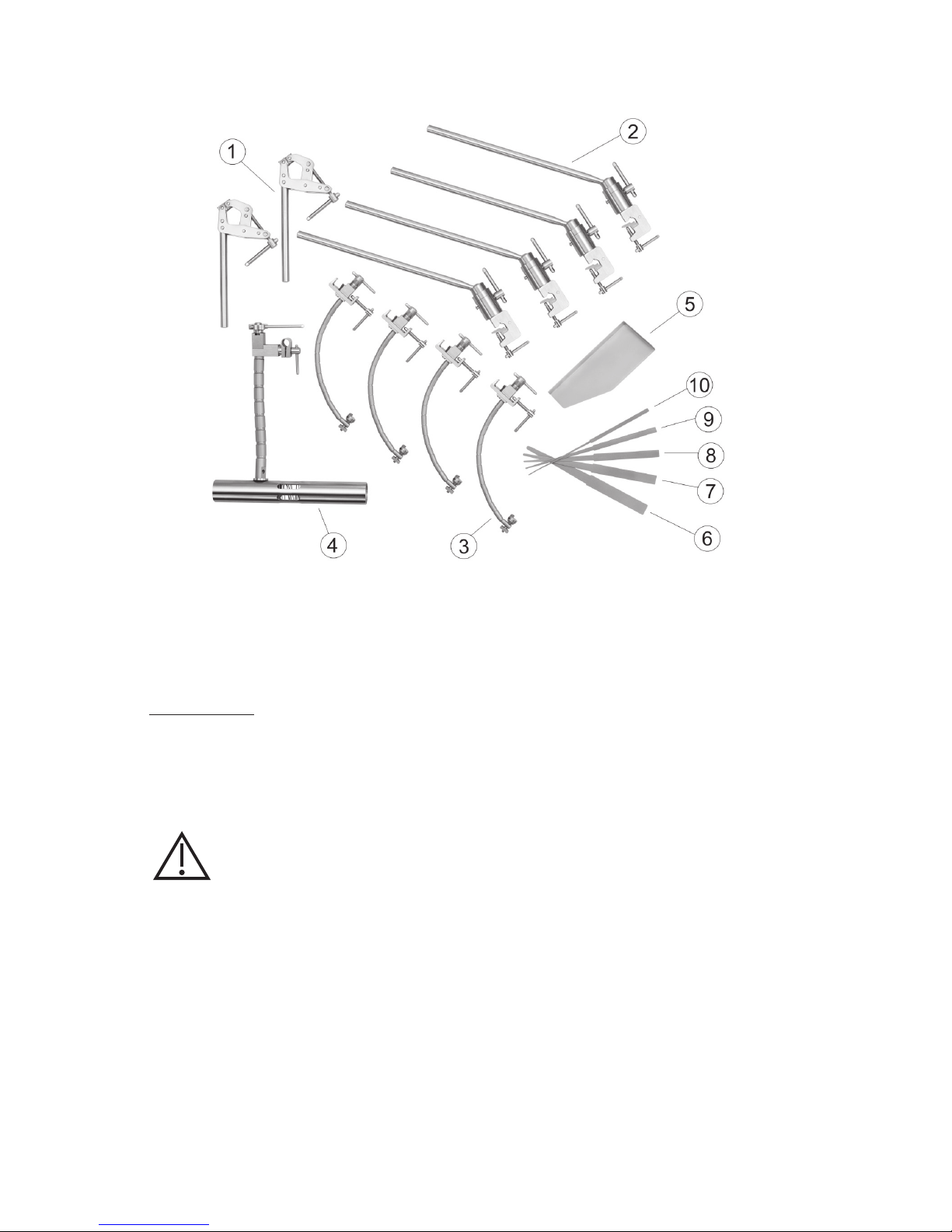
ES – ESPAÑOL
70 71
Figura 1
Inspección
Revise siempre los componentes del sistema de retracción cerebral de Integra antes
y después de cada uso. Si un componente parece dañado y/o parece que no funciona
correctamente, envíe de inmediato el dispositivo a Integra LifeSciences, Cincinnati,
Ohio, para su evaluación y reparación o sustitución (vea la sección Servicio técnico
y reparación).
ATENCIÓN:
El dispositivo no debe usarse si parece dañado o funciona de forma incorrecta. De
lo contrario, puede producir lesiones graves al paciente.
Page 71

ES – ESPAÑOL
Instrucciones de uso
Fijación del dispositivo de fijación craneal MAYFIELD
Las siguientes instrucciones de montaje son para la fijación del sistema de retracción
cerebral de Integra al dispositivo de fijación craneal MAYFIELD (REF. A1013, A1014, A1059,
A1108, A1114 o A2000).
ADVERTENCIA:
El dispositivo se suministra no estéril y requiere esterilización antes de cada uso.
ADVERTENCIA: Si no se leen y siguen las instrucciones incluidas en este manual,
podría producirse un deslizamiento del clavo craneal y ocasionar lesiones graves al
paciente, como laceraciones del cuero cabelludo, fractura craneal o incluso la muerte.
PRECAUCIÓN:
Debe colocarse al paciente en el dispositivo de fijación craneal MAYFIELD y cubrirlo
de la manera habitual.
ADVERTENCIA: Si no se coloca al paciente de forma adecuada y no se aprietan y
aseguran por completo todas las partes ajustables de este dispositivo o de otro similar,
se puede provocar un deslizamiento del clavo craneal y lesiones graves al paciente,
como laceraciones en el cuero cabelludo, fracturas de cráneo o incluso la muerte.
A partir de este punto, el campo es estéril. Todo el proceso de montaje mostrado debe
efectuarse utilizando una técnica estéril.
1. Antes de cada uso, limpie y esterilice todos los componentes del sistema tal y como se
describe en las secciones de Limpieza y Esterilización.
2. Sitúe el dispositivo de fijación craneal MAYFIELD bajo el paño quirúrgico estéril. Fije las
barras primarias sobre el paño estéril alrededor de los soportes verticales del dispositivo
de fijación craneal. Las barras primarias se utilizan para fijar las barras secundarias
flotantes para montar los brazos del retractor y el soporte de manos. Apriete cada
abrazadera de las barras primarias hasta que estas no se muevan en el dispositivo de
fijación craneal vertical (figura 2).
Figura 2
Page 72
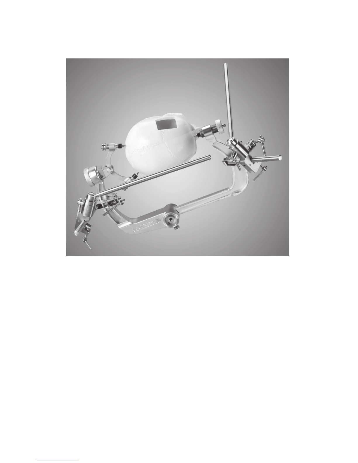
ES – ESPAÑOL
72 73
3. Fije la barra secundaria flotante a cada una de las barras primarias. Apriete cada barra
secundaria flotante hasta que no haya movimiento en las barras primarias (figura 3).
]
Figura 3
La unión universal de las barras secundarias flotantes facilita la colocación de la barra para
montar los brazos del retractor y otros instrumentos.
Page 73

ES – ESPAÑOL
4. Los brazos del retractor y el soporte de manos pueden fijarse a una barra primaria o a una
barra secundaria flotante. Coloque el brazo del retractor o el soporte de manos donde sea
necesario y apriete la abrazadera hasta que no haya movimiento (figura 4).
Figura 4
Una vez que el brazo del retractor o el soporte de manos esté en su sitio, apriete el botón de
ajuste de tensión para mantenerlo en su sitio. Para realizar ajustes en el brazo del retractor
o en el soporte de manos, afloje primero el botón de ajuste de tensión antes de mover y
volver a apretar.
La bandeja Paie y las hojas del retractor están fijadas en los extremos de los brazos del
retractor.
PRECAUCIÓN:
Forzar los brazos del retractor o el soporte de manos para moverlos en dirección
contraria a su tensión de ajuste puede producir que el cable del brazo se desgaste
y posiblemente se rompa. Los segmentos de articulación esférica pueden llegar a perforarse
y el brazo puede tender a desplazarse. Tras un periodo de tiempo, puede experimentarse un
desplazamiento aunque el botón esté apretado. Esto se debe generalmente a que las roscas
de la barra de tracción se desgastan, por lo que será necesario sustituir la pieza.
Page 74

ES – ESPAÑOL
74 75
Fijación de los raíles laterales a la mesa de operaciones
Fije la barra primaria al raíl lateral de la mesa de operaciones. Fije la barra secundaria
flotante a la barra primaria (figura 5). Continúe definiendo el campo quirúrgico utilizando las
barras secundarias flotantes y las barras primarias para fijar los brazos del retractor, las hojas
del retractor y el soporte de manos tal y como se describe anteriormente.
Figura 5
Page 75

ES – ESPAÑOL
Cuidado y Mantenimiento
Los brazos del retractor y el soporte de manos constan de una serie de segmentos de
articulación esférica que forman el brazo flexible, con orificios por los que pasa un cable
de acero. Fijado al cable hay un tornillo ensamblado que está enroscado en una barra de
tracción (figuras 6 y 7).
CONJUNTO DE
ABRAZADERA
ARANDELAS
BOTÓN DE
AJUSTE DE
TENSIÓN
HUECO
EJE
BARRA DE
TRACCIÓN
TORNILLO ENSAMBLADO
QUE ESTÁ ENROSCADO
EN LA BARRA DE
TRACCIÓN
SEGMENTOS DE
ARTICULACIÓN
ESFÉRICA
CABLE
Figura 6: Brazo del retractor
CONJUNTO DE
ABRAZADERA
ARANDELAS
BOTÓN DE
AJUSTE DE
TENSIÓN
HUECO
EJE
BARRA DE
TRACCIÓN
TORNILLO ENSAMBLADO
QUE ESTÁ ENROSCADO
EN LA BARRA DE TRACCIÓN
SEGMENTOS DE
ARTICULACIÓN
ESFÉRICA
CABLE
Figura 7: Soporte de manos
Page 76

ES – ESPAÑOL
76 77
Restablecer la barra de tracción a cero
ADVERTENCIA:
Restablezca la barra de tracción a cero después de cada uso para ayudar a prevenir
el desplazamiento de los brazos flexibles y el daño de la barra de tracción. No
guarde ni esterilice los brazos del retractor ni el soporte de manos mientras el cable esté
bajo tensión.
Cada brazo del retractor y soporte de manos es recibido por el cliente con la barra de
tracción ajustada a cero: el brazo articulado tiene poca holgura o no tiene y la barra de
tracción está totalmente empotrada en el hueco del botón de ajuste de tensión. El brazo
flexible se pone rígido durante la cirugía girando el botón de ajuste de tensión en el sentido
de las agujas del reloj. El eje de la barra de tracción sobresaldrá ligeramente a medida que se
tire del cable. Después de mucho uso, la barra de tracción puede comenzar a sobresalir en
exceso (figuras 8 y 9).
BARRA DE TENSIÓN
SOBRESALIENTE
Figura 8: Brazo del retractor
BARRA DE TENSIÓN
SOBRESALIENTE
Figura 9: Soporte de manos
Page 77

ES – ESPAÑOL
Para salir de este estado, es necesario restablecer la barra de tracción a cero de la siguiente
manera:
1. Sujete el brazo flexible del instrumento con una mano y, con la otra, gire el botón de
ajuste de tensión en el sentido contrario a las agujas del reloj hasta que haga resistencia
(figuras 10 y 11).
GIRAR EL BOTÓN DE
AJUSTE DE TENSIÓN
Figura 10: Brazo del retractor
GIRAR EL BOTÓN DE
AJUSTE DE TENSIÓN
Figura 11: Soporte de manos
Page 78

ES – ESPAÑOL
78 79
2. Sujete el brazo flexible con una mano y, con la otra, gire todo el conjunto de abrazadera
en el sentido de las agujas del reloj. Esto hará avanzar el cable enroscado en la barra de
tracción (figuras 12 y 13).
GIRAR EL
CONJUNTO DE
ABRAZADERA
Figura 12: Brazo del retractor
GIRAR EL
CONJUNTO DE
ABRAZADERA
Figura 13: Soporte de manos
Page 79

ES – ESPAÑOL
Limpieza
Antes de limpiarlo, desmonte el sistema de retracción cerebral de Integra en sus
componentes tal y como se muestra en la figura 1.
No desmonte la unidad del brazo del retractor ni la unidad del soporte de manos. Afloje
la tensión en el botón de ajuste de tensión de cada instrumento, lo que le permitirá una
separación amplia de los segmentos de articulación esférica individuales para su correcta
limpieza.
Después de cada procedimiento, utilice un cepillo y un detergente suaves para quitar todos
los detritos residuales de cada instrumento. Se recomienda que los instrumentos
y las piezas se limpien ultrasónicamente.
Lubricación
Es sumamente importante que las piezas móviles sean lubricadas para mantener estas
piezas funcionales. Se recomienda que todos los componentes sean sumergidos en un
lubricante hidrosoluble antes de su esterilización.
Esterilización
Después de su uso, desmonte y limpie el sistema de retracción cerebral de Integra tal
y como se describe anteriormente. El sistema de retracción cerebral de Integra debe
limpiarse y esterilizarse antes de cada uso.
Esterilice con vapor el sistema de retracción cerebral de Integra de acuerdo con los
siguientes parámetros de esterilización validados.
Esterilización con vapor por prevacío – Ciclo completo:
Temperatura de esterilización: 132 °C
Tiempo de exposición a la esterilización: 8 minutos
Es responsabilidad del usuario validar cualquier parámetro de esterilización que se desvíe de
los indicados anteriormente.
Siga las instrucciones del fabricante del esterilizador para el funcionamiento y la
carga del autoclave de vapor. Todas las superficies de los instrumentos deben estar
directamente expuestas al vapor.
Permita que los componentes se enfríen a temperatura ambiente antes de su uso.
ADVERTENCIA:
No esterilice los brazos del retractor ni el soporte de manos mientras el cable esté
bajo tensión.
Mantenimiento y cuidado
Para garantizar un funcionamiento adecuado y ampliar la vida útil y el rendimiento del
equipo, Integra LifeSciences recomienda lo siguiente:
Acción recomendada Frecuencia recomendada
Devuelva el dispositivo al departamento de reparaciones de
Integra LifeSciences para una inspección y servicio detallados.
Una vez al año
Solicite que Integra NeuroSpecialists lleve a cabo
inspecciones de rutina del dispositivo.
Dos veces al año
Page 80

ES – ESPAÑOL
80 81
Si el equipo no se cuida ni se mantiene de forma adecuada, es posible que detecte efectos
negativos tras procesamientos repetidos con el paso del tiempo, lo que puede reducir el
rendimiento.
Información de contacto: Consulte la información de contacto de la sección Servicio
técnico y reparación sobre cómo devolver el dispositivo para un mantenimiento continuo y
solicitar inspecciones periódicas.
Consulte la sección Notas sobre inspección o mantenimiento para conocer las
comprobaciones de rutina que deben realizarse en el dispositivo.
Eliminación del dispositivo
NOTA: Siga los procedimientos del hospital para eliminar este dispositivo.
Garantía estándar de Integra
INTEGRA LIFESCIENCES CORPORATION (“INTEGRA”) garantiza solo al comprador original que cada
nuevo producto de INTEGRA no presenta defectos de fabricación en el material ni en su fabricación
bajo un uso normal y garantiza el mantenimiento durante un período de un año (excepto en lo
dispuesto expresamente para los elementos accesorios) a partir de la fecha de entrega por parte de
INTEGRA al primer comprador, pero en ningún caso más allá de la fecha de vencimiento que consta en
la etiqueta del producto.
• Se garantiza que los instrumentos quirúrgicos no presentan defectos de material ni de
fabricación siempre que se sometan a un mantenimiento y una limpieza correctos, y se usen
normalmente para los fines previstos.
• Cualquier producto cubierto que INTEGRA proporcione bajo un contrato de alquiler,
arrendamiento o financiación a plazos y que requiera un servicio de reparación durante el plazo de
vigencia de dicho acuerdo deberá ser reparado de conformidad con los términos de dicho acuerdo.
Si se observa algún defecto cubierto durante el período de garantía o durante el plazo establecido
en el acuerdo de compra, el comprador deberá comunicarlo directamente a las oficinas centrales de
INTEGRA. Si los compradores pretenden recurrir a los términos de esta garantía, deberán devolver el
producto a las oficinas centrales de INTEGRA. El producto defectuoso deberá ser devuelto a la mayor
brevedad, empaquetado adecuadamente y con franqueo prepagado. La pérdida o el deterioro durante
la devolución a INTEGRA será un riesgo a cargo del CLIENTE. La única responsabilidad de INTEGRA
bajo esta garantía será la de reparar o reemplazar el producto, a la sola discreción de INTEGRA y a sus
expensas, sujeto a los términos de esta garantía y a los acuerdos pertinentes.
BAJO NINGUNA CIRCUNSTANCIA INTEGRA SERÁ RESPONSABLE DE NINGÚN DAÑO INCIDENTAL,
INDIRECTO, RESULTANTE NI PUNITIVO EN RELACIÓN CON LA ADQUISICIÓN O USO DE CUALQUIER
PRODUCTO DE INTEGRA. Además, esta garantía no se aplicará a, e INTEGRA no será responsable de,
cualquier pérdida relacionada con la compra o uso de cualquier producto de INTEGRA que haya sido
reparado por cualquier otra persona que no sea el representante de servicio técnico autorizado por
INTEGRA o se haya alterado en alguna forma que, a juicio de INTEGRA, haya afectado su estabilidad
o fiabilidad, o haya sido sujeto a uso inadecuado, negligencia o accidente, o se haya usado de alguna
otra forma distinta a lo acordado en las instrucciones proporcionadas por INTEGRA. ESTA GARANTÍA
LIMITADA ES EXCLUSIVA Y SUSTITUYE CUALQUIER OTRA GARANTÍA, EXPRESA O IMPLÍCITA, Y
CUALQUIER OTRA OBLIGACIÓN O RESPONSABILIDAD POR PARTE DE INTEGRA, E INTEGRA NI ASUME
NI AUTORIZA A NINGÚN REPRESENTANTE U OTRA PERSONA A ASUMIR EN SU NOMBRE NINGUNA
OTRA RESPONSABILIDAD EN CONEXIÓN CON LOS PRODUCTOS DE INTEGRA.
INTEGRA NIEGA CUALQUIER OTRA GARANTÍA, EXPRESA O IMPLÍCITA, INCLUIDA CUALQUIER
GARANTÍA DE COMERCIALIZACIÓN O IDONEIDAD PARA UN FIN O APLICACIÓN DETERMINADOS,
O LA APLICACIÓN O LA GARANTÍA DE CALIDAD, ASÍ COMO CUALQUIER GARANTÍA EXPRESA O
IMPLÍCITA PARA LOS PACIENTES. No se puede crear ninguna garantía a partir de una ley o declaración
ni esta Garantía estándar puede ser modificada en ningún modo, excepto por escrito firmado por un
delegado de INTEGRA. Estas limitaciones en la creación o modificación de esta garantía pueden ser
dispensadas o modificadas de forma oral o por algún otro medio.
Page 81

ES – ESPAÑOL
Servicio técnico y reparación
Para el mantenimiento o para reparaciones fuera de Estados Unidos, póngase en contacto con el
representante local autorizado de Integra.
En Estados Unidos, envíe todos los instrumentos para su mantenimiento o reparación a:
Integra LifeSciences Corporation
4900 Charlemar Drive, Building A
Cincinnati, Ohio 45227, EE. UU.
(Incluya siempre el número de orden de compra y una descripción por escrito del problema).
O llame al teléfono: 877-444-1114 (solo para EE. UU.) o +1-513-533-7979
Page 82

82 83
Fabricante:
Mediflex Surgical Products
250 Gibbs Road
Islandia, NY 11749 EE.UU.
Servicios Integra LifeSciences Francia
Immeuble Séquloa 2, 97 allée Alexandre Borodine
Parc Technologique de la Porte des Alpes
69800 Saint Priest — Francia
+33(0) 437 47 59 1
Integra y el logotipo de Integra son marcas comerciales registradas de Integra LifeSciences Corporation
en Estados Unidos o en otros países. MAYFIELD es una marca comercial registrada de SM USA, Inc., e
Integra la utiliza bajo licencia.
©2018 Integra LifeSciences Corporation. Reservados todos los derechos. 451A2012 07/18 Rev. BA 0991735-1
Page 83

MAYFIELD® gemodificeerde
zwenkadapter
( A2012)
Gebruikershandleiding
Gedistribueerd door:
Integra LifeSciences Corporation
4900 Charlemar Drive, Building A
Cincinnati, OH 45227, USA
Tel: 513-533-7979
Fax: 513-271-1915
integralife.com
Fabrikant:
Mediflex Surgical Products
250 Gibbs Road
Islandia, NY 11749 USA
Integra LifeSciences Services France
Immeuble Séquloa 2, 97 allée Alexandre Borodine
Parc Technologique de la Porte des Alpes
69800 Saint Priest – Frankrijk
+33(0) 437 47 59 1
NL – Nederlands
0086
Page 84
NL – NEDERLANDS
84 85
Aentie
Het product voldoet aan de eisen van richtlijn 93/42/EEG
Fabrikant
Gevolmachtigd vertegenwoordiger in de Europese Unie
Raadpleeg vóór gebruik de gebruiksaanwijzing.
Let op: De Amerikaanse federale wetgeving beperkt de verkoop
van dit apparaat tot verkoop door, of op voorschri van, een
bevoegde arts
Catalogusnummer
Fabricagedatum (JJJJ-MM-DD)
Lotnummer
Serienummer
Betekenis van de in deze handleiding gebruikte symbolen NEDERLANDS
VOORZICHTIG!
Gevaren die apparatuur- of eigendomsschade tot gevolg kunnen hebber
WAARSCHUWING!
Gevaren die ernstig persoonlijk letsel of de dood tot gevolg kunnen hebber
Page 85

NL – NEDERLANDS
NEDERLANDS
Gebruiksindicaties
Het Integra® Brain Retractor System is geïndiceerd voor het terugtrekken van hersenweefsel
tijdens neurochirurgische ingrepen. Het Integra Brain Retractor System kan worden gebruikt
in combinatie met MAYFIELD®-schedelklemmen (REF. NR. A1013, A1014, A1059, A1108, A1114
en A2000), of kan aan de zijstangen van de operatietafel worden bevestigd.
Het Integra Brain Retractor System doet ook dienst ter ondersteuning, en voor het plaatsen
van de verschillende instrumenten en handsteunen.
Beschrijving
Het Integra Brain Retractor System bestaat uit een stel componenten waarmee de chirurg
een kader rondom de operatieplaats kan construeren voor het terugtrekken van weefsel
tijdens een neurochirurgische ingreep. Het systeem omvat twee primaire staven met
klemmen die na steriele afdekking aan de schedelklem worden bevestigd. Langere,
verplaatsbare secundaire staven worden daarna aan de primaire staven of aan elkaar
vastgeklemd. De retractorarmen kunnen aan de verplaatsbare secundaire staven worden
bevestigd, en gebruikt worden om verschillende instrumenten te ondersteunen en te
plaatsen, zoals de retractorbladen van het Integra Brain Retractor System. Er kunnen tevens
suctieapparaten, ontleders, scharen, boren en handsteunen op worden bevestigd.
Systeemcomponenten
Het Integra Brain Retractor System omvat de volgende componenten (aeelding 1):
1. Primaire staven (2 stuks)
2. Verplaatsbare secundaire staven (4 stuks)
3. Retractorarmen (4 stuks)
4. Handsteun
5. Tray voor paies
6. Taps aflopend retractorblad, 6,4 mm tot 19,1 mm (1/4 tot 3/4 inch)
7. Taps aflopend retractorblad, 4,0 mm tot 15,9 mm (5/32 tot 5/8 inch)
8. Taps aflopend retractorblad, 3,2 mm tot 12,7 mm (1/8 tot 1/2 inch)
9. Taps aflopend retractorblad, 2,4 mm tot 9,5 mm (3/32 tot 3/8 inch)
10. Taps aflopend retractorblad, 1,6 mm tot 6,4 mm (1/16 tot 1/4 inch)
11. Sterilisatiehoes (niet afgebeeld)
Page 86

NL – NEDERLANDS
86 87
Aeelding 1
Inspectie
Controleer de componenten van het Integra Brain Retractor System vóór en na elk gebruik.
Als een onderdeel beschadigd schijnt te zijn en/of niet goed schijnt te werken, moet het
medische hulpmiddel onmiddellijk naar Integra LifeSciences, Cincinnati, Ohio, VS, worden
gezonden voor evaluatie en reparatie of vervanging (zie ‘Service en reparatie’).
WAARSCHUWING:
Het instrument mag niet worden gebruikt wanneer het beschadigd lijkt te zijn of
niet goed functioneert. Dit kan tot ernstig letsel bij de patiënt leiden.
Page 87
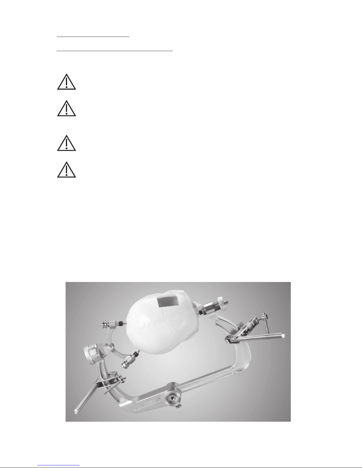
NL – NEDERLANDS
Gebruiksaanwijzing
Bevestiging van de MAYFIELD-schedelklem
Onderstaande montage-instructies gelden voor de bevestiging van het Integra Brain Retractor
System aan een MAYFIELD-schedelklem (REF. A1013, A1014, A1059, A1108, A1114 of A2000).
WAARSCHUWING:
Het medische hulpmiddel wordt niet-steriel geleverd en moet vóór elk gebruik
gesteriliseerd worden.
WAARSCHUWING: Indien de instructies in de productbijsluiter niet worden gelezen
en opgevolgd, kan dit ertoe leiden dat de schedelpen wegglijdt en bij de patiënt
ernstig letsel veroorzaakt, zoals laceraties aan de hoofdhuid, een schedelfractuur of
zelfs de dood.
VOORZICHTIG:
De patiënt moet in de MAYFIELD-schedelklem worden geplaatst en op de normale
wijze worden afgedekt.
WAARSCHUWING: Indien de patiënt niet juist wordt gepositioneerd of indien niet alle
verstelbare delen van dit of enig vergelijkbaar instrument volledig worden aangedraaid en
vastgezet, kan dit ertoe leiden dat de schedelpen wegglijdt en bij de patiënt ernstig letsel
veroorzaakt, zoals laceraties aan de hoofdhuid, een schedelfractuur of zelfs de dood.
Vanaf dit punt is het veld steriel. Het hele getoonde montageproces wordt uitgevoerd
met steriele techniek.
1. Vóór elk gebruik moeten alle systeemcomponenten worden gereinigd en gesteriliseerd,
zoals beschreven in ‘Reiniging en sterilisatie’.
2. Zoek de MAYFIELD-schedelklem onder het steriele operatielaken. Bevestig de primaire
staven over het steriele laken rondom de verticale stijlen van de schedelklem. De primaire
staven worden gebruikt voor bevestiging van de verplaatsbare secundaire staven om
de retractorarmen en handsteun te monteren. Maak elke primaire staalem stevig vast,
zodat de klem niet op de stijl van de schedelklem kan bewegen (aeelding 2).
Aeelding 2
Page 88
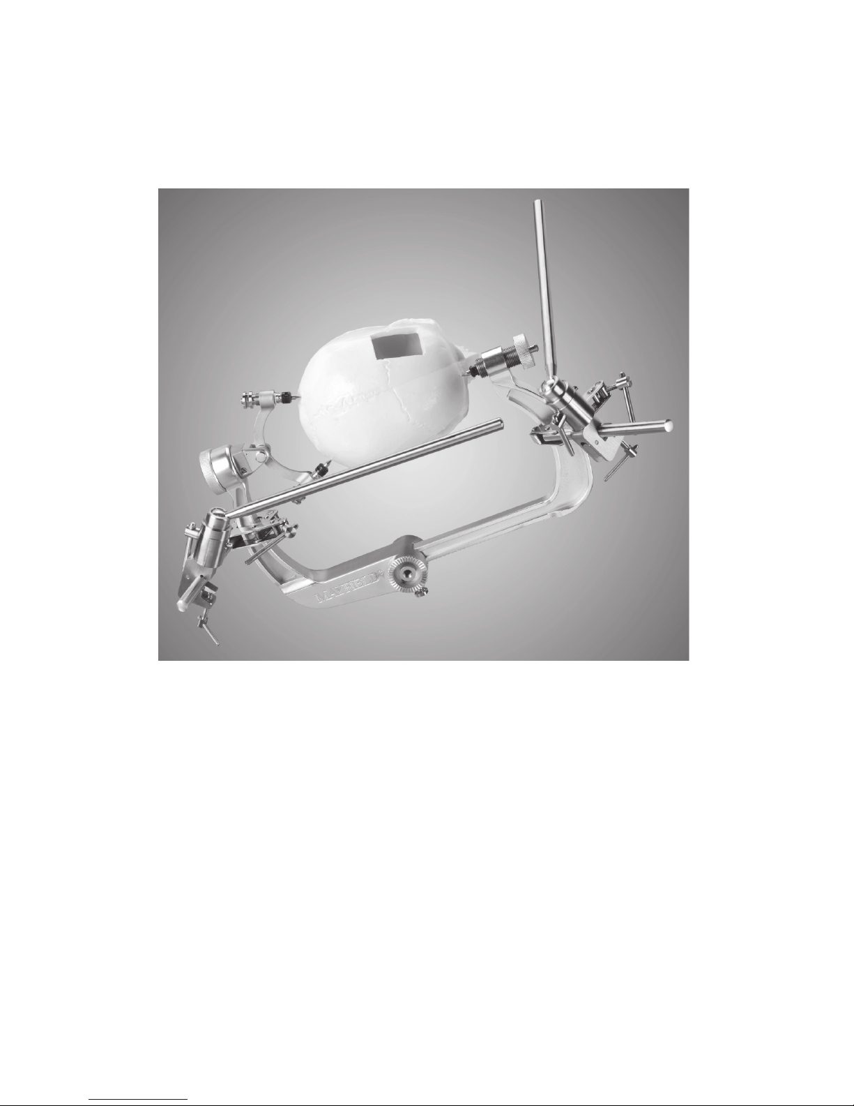
NL – NEDERLANDS
88 89
3. Bevestig een verplaatsbare secundaire staaf op elke primaire staaf. Maak elke
verplaatsbare secundaire staaf stevig vast, zodat er geen beweging op de primaire staven
mogelijk is (aeelding 3).
Aeelding 3
Het universele scharnier van de verplaatsbare secundaire staven vergemakkelijkt de
plaatsing van de staaf voor het monteren van de retractorarmen en andere hulpmiddelen.
Page 89
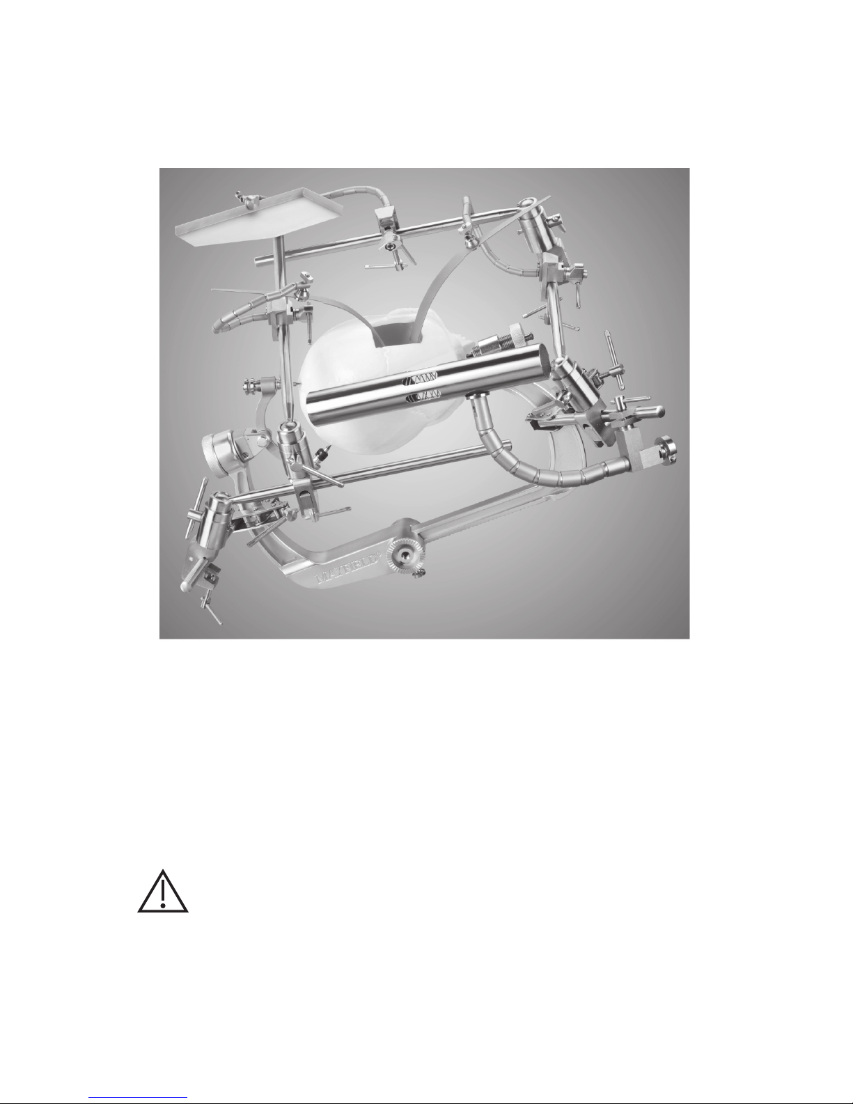
NL – NEDERLANDS
4. De retractorarmen en handsteun kunnen aan een primaire staaf of verplaatsbare
secundaire staaf worden bevestigd. Plaats de retractorarm of handsteun waar benodigd,
en haal de klem aan totdat er geen beweging meer plaatsvindt (aeelding 4).
Aeelding 4
Zodra de retractorarm of de handsteun geplaatst is, moet de spanningsregelaar worden
aangehaald om de arm op zijn plaats te houden. Om de retractorarm of handsteun bij te
stellen moet vóór het verplaatsen van de arm of steun de spanningsregelaar eerst worden
losgedraaid en daarna opnieuw worden aangehaald.
De tray voor paies en retractorbladen worden aan de uiteinden van de retractorarmen
bevestigd.
VOORZICHTIG:
Beweging van de retractorarmen of handsteun forceren tegen de aangehaalde
spanning ervan kan tot slijtage en mogelijke breuk van de kabel in de arm leiden.
De kogelscharniersegmenten kunnen bekrast raken en de arm kan beginnen af te wijken.
Na verloop van tijd kan zich afwijking voordoen, zelfs als de knop stevig is aangehaald.
Doorgaans is dit te wijten aan versleten draden van de trekbalk, wat vervanging van het
onderdeel noodzakelijk maakt.
Page 90

NL – NEDERLANDS
90 91
Bevestiging aan de zijstangen van de operatietafel
Bevestig een primaire staaf aan de zijstang van de operatietafel. Bevestig een verplaatsbare
secundaire staaf aan de primaire staaf (aeelding 5). Blijf het chirurgische veld inrichten
met de verplaatsbare secundaire staven en de primaire staven voor het bevestigen van de
retractorarmen, retractorbladen en de handsteun, zoals hierboven beschreven.
Aeelding 5
Page 91
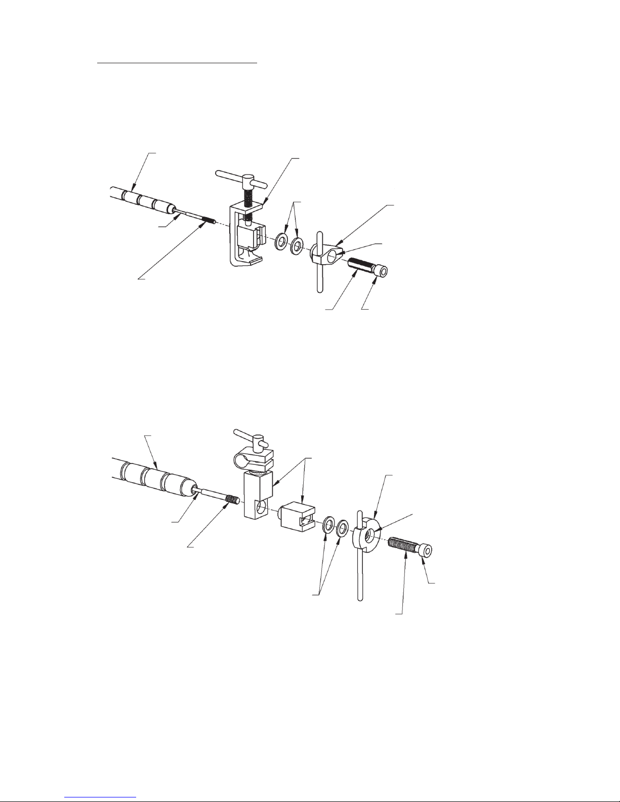
NL – NEDERLANDS
Verzorging en onderhoud
De retractorarmen en de handsteun bestaan uit een reeks kogelscharniersegmenten die
de flexibele arm vormen, met gaten waardoor een stalen kabel loopt. Aan de kabel is een
zetschroef bevestigd die in een trekstang wordt geschroefd (aeelding 6 en 7).
KLEM-
MONTAGE
SLUIT-
RINGEN
SPANNINGSREGELAAR
HOLTE
NAAFTREKSTANG
ZETSCHROEF IN
TREKSTANG GESCHROEFD
KOGELSCHAR-
NIERSEGMENTEN
KABEL
Aeelding 6: Retractorarm
KLEM-
MONTAGE
SLUIT-
RINGEN
SPANNINGSREGELAAR
HOLTE
NAAF
TREKSTANG
ZETSCHROEF IN
TREKSTANG GESCHROEFD
KOGELSCHAR-
NIERSEGMENTEN
KABEL
Aeelding 7: Handsteun
KOGELSCHARNIERSEGMENTEN
KOGELSCHARNIERSEGMENTEN
Page 92

NL – NEDERLANDS
92 93
De trekstang opnieuw op nul instellen
WAARSCHUWING:
De trekstang moet na elk gebruik opnieuw op nul worden ingesteld om afwijking
van de flexibele armen en schade aan de trekstang te helpen voorkomen. De
retractorarmen of de handsteun niet opbergen of steriliseren wanneer de kabel onder
spanning is.
Elke retractorarm en handsteun hee bij ontvangst door de klant de trekstang op nul
ingesteld. De scharnierarm hee weinig of geen speling en de trekstang zit volledig in de
holte van de spanningsregelaar teruggetrokken. De flexibele arm wordt tijdens de operatie
verstevigd door de spanningsregelaar naar rechts te draaien. De naaf van de trekbalk zal iets
uitsteken wanneer aan de kabel wordt getrokken. Na veelvuldig gebruik is het mogelijk dat
de trekstang te ver gaat uitsteken (aeelding 8 en 9).
ERUIT STEKENDE
TREKSTANG
Aeelding 8: Retractorarm
ERUIT STEKENDE
TREKSTANG
Aeelding 9: Handsteun
Page 93

NL – NEDERLANDS
Om deze conditie te verhelpen moet de trekstang als volgt opnieuw op nul worden
ingesteld:
1. Houd de flexibele arm van het instrument in de ene hand en draai met de andere hand de
spanningsregelaar naar links totdat er weerstand optreedt (aeelding 10 en 11).
DE SPANNINGSREGELAAR
DRAAIEN
Aeelding 10: Retractorarm
DE SPANNINGSREGELAAR
DRAAIEN
Aeelding 11: Handsteun
Page 94

NL – NEDERLANDS
94 95
2. Houd de flexibele arm in de ene hand en draai met de andere hand de hele klemmontage
naar rechts. Hierdoor wordt de schroeabel in de trekstang opgevoerd (aeelding 12 en
13).
DE KLEM
MONTAGE
DRAAIEN
Aeelding 12: Retractorarm
DE KLEM
MONTAGE
DRAAIEN
Aeelding 13: Handsteun
Page 95

NL – NEDERLANDS
Reiniging
Voordat met reinigen wordt begonnen moeten alle componenten van het Integra Brain
Retractor System worden gedemonteerd, zoals in aeelding 1 wordt getoond.
De retractorarm- of handsteunmontage niet demonteren. Draai de spanningsregelaar
op elk instrument los, zodat er voldoende ruimte is tussen de afzonderlijke
kogelscharniersegmenten om goed te kunnen reinigen.
Na elke ingreep alle resterende vuil uit de instrumenten verwijderen met een zachte borstel
en zacht detergens. Het verdient aanbeveling de instrumenten en onderdelen ultrasoon te
reinigen.
Smering
Het is van uitzonderlijk belang dat beweegbare onderdelen worden gesmeerd om ze
in goedwerkende staat te houden. Het verdient aanbeveling alle onderdelen vóór de
sterilisatie in een in water oplosbaar smeermiddel onder te dompelen.
Sterilisatie
Na gebruik het Integra Brain Retractor System demonteren en reinigen, zoals hierboven
beschreven. Het Integra Brain Retractor System moet vóór ieder gebruik worden gereinigd
en gesteriliseerd.
Het Integra Brain Retractor System met stoom steriliseren volgens de onderstaande
gevalideerde sterilisatieparameters.
Prevacuüm met stoomsterilisatie – volledige cyclus:
Sterilisatietemperatuur: 132 °C
Blootstellingstijd tijdens sterilisatie: 8 minuten
De gebruiker is ervoor verantwoordelijk de sterilisatieparameters te valideren die van de
bovenstaande afwijken.
Volg de instructies van de sterilisatorfabrikant voor de werking en het laden van de
stoomautoclaaf. Alle oppervlakken van de instrumenten moeten direct aan de stoom
worden blootgesteld.
De componenten tot kamertemperatuur laten aoelen voordat u ze gebruikt.
WAARSCHUWING:
De retractorarmen of handsteun niet steriliseren terwijl de kabel onder spanning
staat.
Onderhoud en zorg
Om een juiste werking te garanderen en de levensduur en prestaties van de instrumenten te
verlengen, beveelt Integra LifeSciences het volgende aan:
Aanbevolen actie Aanbevolen frequentie
Retourneer het instrument aan de afdeling Repairs (reparaties) van
Integra LifeSciences voor nauwkeurige inspectie en onderhoud.
Eenmaal per jaar
Verzoek aan Integra NeuroSpecialists om een routinematige
inspectie van het instrument.
Tweemaal per jaar
Page 96

NL – NEDERLANDS
96 97
Zonder goede verzorging en onderhoud van het instrument kunnen na herhaalde
behandeling voor hergebruik in de loop van de tijd negatieve effecten optreden, die tot
verminderde prestaties kunnen leiden.
Contactinformatie: Zie het onderdeel Service en Reparatie voor contactinformatie over hoe
u het instrument kan retourneren voor periodiek onderhoud, en voor het aanvragen van
periodieke inspecties.
Zie het onderdeel Inspectie en/of Onderhoudsaantekeningen voor regelmatige controles
die op het instrument moeten worden uitgevoerd.
Instrument afvoeren
NB Volg de ziekenhuisprocedures voor de afvoer van dit instrument.
Standaardgarantie van Integra
INTEGRA LIFESCIENCES CORPORATION (‘INTEGRA’) garandeert de oorspronkelijke koper uitsluitend
dat elk nieuw INTEGRA -product vrij van fabricagefouten is voor wat betre materialen en
vervaardiging bij normaal gebruik en onderhoud gedurende één jaar (behalve waar uitdrukkelijk anders
wordt bepaald voor accessoire-items) vanaf de leveringsdatum door INTEGRA aan de eerste koper,
maar in geen geval langer dan de op het productetiket vermelde vervaldatum.
• Chirurgische instrumenten zijn gegarandeerd vrij van materiaal- en productiedefecten indien ze
op de juiste wijze worden onderhouden en gereinigd, en op de normale wijze worden gebruikt
voor het bestemde doel.
• Elk product onder garantie dat door INTEGRA op basis van een lease-, huur- of
financieringsovereenkomst wordt geleverd en gedurende de looptijd van een dergelijke
overeenkomst reparatieservice nodig hee, zal worden gerepareerd volgens de voorwaarden
van die overeenkomst.
Indien een onder garantie gedekt defect zich tijdens de garantieperiode of -termijn van die
leveringsovereenkomst voordoet, moet de koper rechtstreeks contact opnemen met het hoofdkantoor
van INTEGRA. Indien kopers zich op de voorwaarden van deze garantie willen beroepen, moet het
product aan het hoofdkantoor van INTEGRA geretourneerd worden. Het defecte product moet
onmiddellijk franco en in de juiste verpakking geretourneerd worden. Verlies of beschadiging van
de retourzending aan INTEGRA is voor risico van de KLANT. De enige verantwoordelijkheid van
INTEGRA onder deze garantie zal reparatie of vervanging zijn volgens de exclusieve keuze en op
kosten van INTEGRA, aankelijk van de voorwaarden van deze garantie en de van toepassing zijnde
overeenkomsten.
IN GEEN ENKEL GEVAL ZAL INTEGRA AANSPRAKELIJK ZIJN VOOR OM HET EVEN WELKE BIJKOMENDE,
INDIRECTE, GEVOLG- OF STRAFVERGOEDENDE SCHADE IN VERBAND MET DE AANSCHAF OF HET
GEBRUIK VAN EEN INTEGRA-PRODUCT. Deze garantie is tevens niet van toepassing op, en INTEGRA
zal niet verantwoordelijk zijn voor om het even welk verlies dat wordt geleden in verband met de
aankoop of het gebruik van een INTEGRA-product dat gerepareerd wordt door iemand anders dan een
erkende INTEGRA-servicevertegenwoordiger, dan wel zodanig gewijzigd is dat dit, volgens het oordeel
van INTEGRA, op de stabiliteit of betrouwbaarheid van invloed was of het product aan misbruik,
onachtzaamheid of een ongeluk onderworpen is geweest, of op andere wijze dan in overeenstemming
met de door INTEGRA verstrekte instructies werd gebruikt. DEZE BEPERKTE GARANTIE IS EXCLUSIEF
EN KOMT IN DE PLAATS VAN ALLE ANDERE GARANTIES, UITDRUKKELIJK OF STILZWIJGEND, EN
VAN ALLE ANDERE VERPLICHTINGEN OF AANSPRAKELIJKHEDEN VOOR WAT INTEGRA BETREFT,
EN INTEGRA AANVAARDT NOCH AUTORISEERT OM HET EVEN WELKE VERTEGENWOORDIGER
OF ANDERE PERSOON ENIGE ANDERE AANSPRAKELIJKHEID NAMENS HAAR TE AANVAARDEN IN
VERBAND MET DE PRODUCTEN VAN INTEGRA.
INTEGRA VERWERPT ALLE ANDERE GARANTIES, UITDRUKKELIJK OF IMPLICIET, INCLUSIEF IMPLICIETE
GARANTIES VAN VERKOOPBAARHEID OF GESCHIKTHEID VOOR EEN BEPAALD DOEL, OF ELKE
TOEPASSINGS- OF KWALITEITSGARANTIE, EVENALS ENIGE EXPLICIETE OF IMPLICIETE GARANTIE
VOOR PATIËNTEN. Geen garantie of waarborg kan ontstaan door welke handeling of verklaring ook,
Page 97
NL – NEDERLANDS
en deze standaardgarantie mag op geen enkele wijze worden gewijzigd, behalve via een door een
daartoe bevoegde functionaris van INTEGRA ondertekend schrijven. Deze beperkingen op het ontstaan
of wijzigen van deze garantie kunnen niet mondeling of op een andere wijze worden opgeschort of
gemodificeerd.
Service en reparatie
Voor service en reparaties buiten de Verenigde Staten neemt u contact op met uw plaatselijke, erkende
Integra-vertegenwoordiger.
In de Verenigde Staten stuurt u alle instrumenten voor service of reparatie naar:
Integra LifeSciences Corporation
4900 Charlemar Drive, Building A
Cincinnati, Ohio 45227, VS
(Altijd het nummer van de bestelbon en een schrielijke beschrijving van het probleem bijvoegen.)
Of telefonisch: 877-444-1114 (alleen VS) of +1-513-533-7979
Fabrikant:
Mediflex Surgical Products
250 Gibbs Road
Islandia, NY 11749 VS
Integra LifeSciences Services France
Immeuble Séquloa 2, 97 allée Alexandre Borodine
Parc Technologique de la Porte des Alpes
69800 Saint Priest – Frankrijk
+33(0) 437 47 59 1
Integra en het Integra-logo zijn geregistreerde handelsmerken van Integra LifeSciences Corporation in
de Verenigde Staten en/of andere landen. MAYFIELD is een geregistreerd handelsmerk van SM USA, Inc.
en wordt gebruikt door Integra onder licentie.
©2018 Integra LifeSciences Corporation. Alle rechten voorbehouden. 451A2012 07/18 Rev. BA 0991735-1
Page 98

Manufacturer:
Mediflex Surgical Products
250 Gibbs Road
Islandia, NY 11749 USA
Integra LifeSciences Services France
Immeuble Séquloa 2, 97 allée Alexandre Borodine
Parc Technologique de la Porte des Alpes
69800 Saint Priest - France
+33(0) 437 47 59 1
Integra and the Integra logo are registered trademarks of Integra LifeSciences Corporation in the United
States and/or other countries. MAYFIELD is a registered trademark of SM USA, Inc. and is used by
Integra under license.
2018 Integra LifeSciences Corporation. All Rights Reserved. 451A2012 07/18 Rev. BA 0991735-1
 Loading...