Insinkerator W-152 Service Manual

|
ISE |
INSTALLATION, CARE AND USE INSTRUCTIONS |
|
MODELS |
|
|
IN-SINK-ERATOR |
W-152 and W-154 |
|
|
|
IMPORTANT SAFETY INSTRUCTIONS
this manual.
When using electrical appliances, basic safety precautions to reduce the risk of fire, electric shock, or injury to persons should be followed, including:
1.READ ALL INSTRUCTIONS BEFORE USING THIS WATER HEATER,
2.This water heater must be grounded. Connect only to properly grounded outlet. See "GROUNDING INSTRUCTIONS" found on page 3.
3.Install or locate this water heater only in accordance with the provided installation instructions.
4.Use this water heater only for its intended use as described in
5.Do not use an extension cord set with this water heater. If no receptacle is available adjacent to the water heater, contact a
qualified electrician to have one properly installed.
6.As with any appliance, close supervision is necessary when used by children.
7.Do not operate this water heater if it has a damaged cord or plug, if it is not working properly, or if it has been damaged or
dropped.
8.This water heater should be serviced only by qualified service personnel. Contact nearest authorized service facility tor
examination, repair, or adjustment.
SAVE THESE INSTRUCTIONS
THIS HEATER IS DESIGNED TO SUPPLY A LIMITED AMOUNT OF HOT WATER TO REMOTE LOCATION OR LOW WATER USE LAVATORIES. TANK VOLUME IS 2-1/2 GALLONS FOR MODEL W-152 AND 4 GALLONS FOR MODEL W-154.
KEEP THIS WARRANTY AND MANUAL NEAR THE HEATER FOR FUTURE REFERENCE WHENEVER MAINTENANCE ADJUSTMENT OR SERVICE IS REQUIRED.
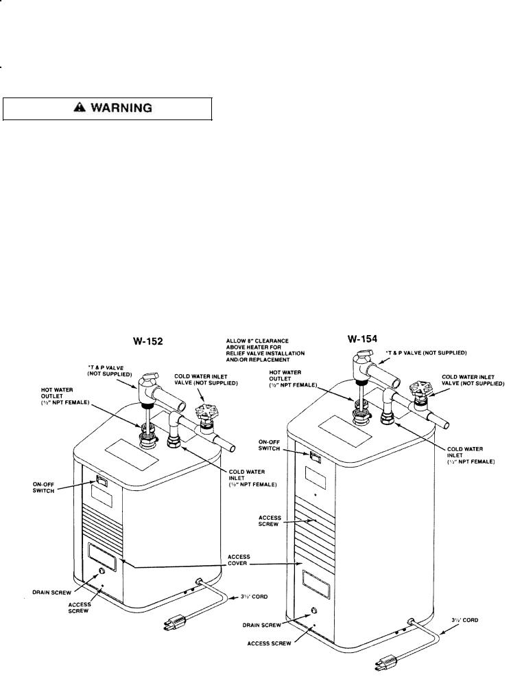
THIS PAGE SHOWS TYPICAL WATER HEATER INSTALLATION.
* INSTALL IN ACCORDANCE WITH ALL LOCAL CODES.
+ CONSULT LOCAL CODE AND NATIONAL ELECTRICAL CODE FOR PROPER INSTALLATION.

SPECIFICATIONS
TANK
Operating Pressure
Material
Capacity (Approx.)
ELECTRICAL
Rating
Heater
Power Cord
THERMOSTAT
INSULATION
W-152 |
W-154 |
150psi (Max.) |
150psi (Max.) |
Bronze |
Bronze |
2-1 /2 Gallon |
4 Gallon |
|
|
1500 Watts, 12.5 Amps @ 120 Volt Replaceable 1" screw-in type
3 conductor, 3-1/2 Ft.
Combination adjustable thermostat (110°-170°F) and resettable high temperature cutout. (Thermostat is pre-set at approximately 120°F.)
FITTINGS
Water Inlet & Outlet
T & P Relief Valve (Not Supplied)
Drain
STANDBY HEAT LOSS*
@ 120°F (75°F Ambient)
FIRST HOUR RATING**
@ 80°F Rise
USABLE HOT WATER*** |
1/2 GPM |
(25% Temp. Drop) |
1 GPM |
|
2 GPM |
SHIPPING WEIGHT |
|
OVERALL DIMENSION |
|
(See Pg. 8) |
|
High efficiency EPS meets U.L. 94 HF-1 flammability specification.
1 /2" NPT Female 3/4" NPT Female 1 /4" Screw Fitting
0.25 KWHr |
0.50 KWHr |
|
|
|
|
8.6 Gallon |
10.4 Gallon |
|
|
|
|
2.0 Gallon |
30 Gallon |
|
|
1.62 Gallon |
3.0 Gallon |
|
|
1.25 Gallon |
3.0 Gallon |
|
|
|
|
18 lb. |
23 lb. |
|
|
13-1 /2"H x 10-1 /2"W x 10-1 /4"D |
20-5/8"H x 10-1 /2"W x 10-1 /4"D |
|
|
*STANDBY HEAT LOSS - Measure of how well the tank is insulated. Use a Kilowatt Hour meter and measure the power consumed in a 24 Hr. period for a full tank at normal operating temperature and no water being added.
** FIRST HOUR RATING - Measure how much hot water can be delivered over a one hour period, with a 140°F tank water temperature and 60°F incoming water temperature.
***USABLE HOT WATER - Measure of how the cold incoming water mixes with the stored hot water. Start with a hot tank. Draw water at 1 /2 GPM until water temperature drops 25%. Measure amount of water drawn. Repeat for 1 GPM and 2 GPM.
2

installation
TEXT PRINTED OR OUTLINED IN RED CONTAINS INFORMATION RELATIVE
TO YOUR SAFETY. PLEASE READ THOROUGHLY BEFORE USING APPLIANCE.
REQUIRED ABILITY
INSTALLATION OR SERVICE OF THIS WATER HEATER REQUIRES ABILITY EQUIVALENT TO THAT OF A LICENSED TRADESMAN IN THE FIELD INVOLVED. PLUMBING AND ELECTRICAL WORK ARE INVOLVED.
GENERAL
The installation must conform to these instructions, the local code authority having jurisdiction, and the requirements of the power company. In the absence of code requirements follow NFPA-70, The National Electrical Code, which may be ordered from: American Standards Institute, 1430 Broadway, New York, NY 10018.
"INSULATION BLANKETS" ARE AVAILABLE FOR EXTERNAL USE ON ELECTRIC WATER HEATERS. BUT ARE NOT RECOMMENDED BY IN-SINK-ERATOR.
IF YOU CHOOSE TO IGNORE OUR RECOMMENDATION AND INSTALL AN INSULATION BLANKET ON THIS HEATER YOU MUST ADHERE TO THE FOLLOWING PRECAUTIONS IN ORDER TO PREVENT SERIOUS INJURY OR DEATH TO YOURSELF OR OTHERS.
1. THE JUNCTION BOX, EXTERNAL WIRING, THERMOSTATS OR HEATING ELEMENTS ON ELECTRIC WATER HEATERS MUST NOT BE COVERED.
2.THE TEMPERATURE-PRESSURE RELIEF VALVE MUST NOT BE COVERED.
3OPERATING INSTRUCTIONS, INSTALLATION OR SAFETY RELATED LABELS MUST NOT BE COVERED.
4THE AMERICAN NATIONAL STANDARDS & FEDERAL LAWS PERTAINING TO WATER HEATERS REQUIRE THAT INSTRUCTIONS & SAFETY LABELS REMAIN ON THE WATER HEATER PROPER. DO NOT REMOVE INSTRUCTIONS OR SAFETY LABELS FROM THE HEATER.
5.IN-SINK-ERATOR WILL NOT BE LIABLE FOR ANY INCIDENT RESULTING FROM THE USE OF INSULATION BLANKETS.
6.WATER AND/OR CONDENSATE CAN COLLECT IN AN INSULATION BLANKET. IN-SINK-ERATOR WILL NOT BE LIABLE FOR ANY RUST OR CORROSION DAMAGE CAUSED BY THE INSTALLATION OF INSULATION BLANKETS.
FAILURE TO FOLLOW THESE INSTRUCTIONS CAN RESULT IN SERIOUS PERSONAL INJURY OR DEATH.
GROUNDING INSTRUCTIONS
This appliance must be grounded. In the event of a malfunction or breakdown, grounding provides a path of least resistance for electric current to reduce the risk of electric shock. This appliance is equipped with a cord having an equipment-grounding conductor and a grounding plug. The plug must be plugged into a three pin receptacle that is properly installed and grounded in accordance with all local codes and ordinances.
Have a licensed electrician check for ground continuity of the electrical supply system to insure proper grounding of the water heater.
TEMPERATURE AND PRESSURE RELIEF VALVE
To reduce the risk of excessive pressures and temperatures in this water heater install temperature and pressure protective equipment required by local codes but not less than a combination temperature and pressure relief valve certified by a nationally recognized testing laboratory that maintains periodic inspection of production of listed equipment or materials, as meeting the requirements for Relief Valves and Automatic Gas Shutoff Devices for Hot Water Supply Systems, ANSI Z21.22. This valve must be marked with a maximum set pressure not to exceed the marked maximum working pressure of the water heater. Install the valve into an opening provided and marked for this purpose in the water heater, and orient it or provide tubing so that any discharge from the valve will exit only within 6 inches above or at any distance below the structural floor and cannot contact any live electrical part. The discharge opening must not be blocked or reduced in size under any circumstances.
Check the metal tag on the relief valve and compare it to the
3
 Loading...