


DISPOSER CONTROL CENTERS
SERVICE MANUAL CC-101 SERIES COMMERCIAL DISPOSER CONTROL CENTERS
(INCLUDES WIRING DIAGRAMS)
SEE PREFACE FOR MODEL REFERENCE
IN-SINK-ERATOR DIVISION
EMERSON ELECTRIC CO.
4700 21st STREET, RACINE, WI 53406

TABLE OF CONTENTS
SECTION |
PAGE NO. |
||
1 |
Safety Precautions |
|
1-1 |
2 |
Preface |
|
2-1 |
3 |
General Information |
|
3-1 |
4 |
Wiring Diagrams |
|
4-1 |
5 |
Plumbing, Motor and Line Voltage Connections |
5-1 |
|
6 |
Subpanel Removal and Replacement |
|
6-1 |
7 |
Component Description |
|
7-1 |
8 |
Component Location |
|
8-1 |
9 |
Operating Sequence |
|
9-1 |
10 |
Component Testing and Replacement |
|
10-1 |
11 |
Troubleshooting |
|
11-1 |
12 |
Information Tips |
|
12-1 |
13 |
Special Equipment |
|
13-1 |
14 |
Glossary of Terms |
|
14-1 |
15 |
Technical Data Sheets (How the Control Center Works) |
||
|
CC-101 B |
|
15-2 |
|
CC-101 C & CC-101D |
|
15-10 |
|
CC-101 E |
|
15-18 |
|
CC-101 G & CC-101H |
|
15-26 |

PREFACE |
SECTION 2 |
A Control center is a device used to start and stop a commercial disposer by the use of two push-button switches. It is commonly referred to as a control panel and contains various electrical component parts. The main functions of the control panel are to reverse the direction of the disposer motor each time it is started, start the water flow to the disposer, and allow it to flow for several minutes after the disposer is turned off.
This manual includes CC-101 series control centers manufactured since 1976 (i.e., CC-101 A through CC-101 G). Basic functions remained the same throughout the CC-101 series, but component parts changed, and eventually additional features were added.
NOTE
Once the function and purpose of each component is learned, control centers manufactured before 1976 can also be diagnosed. If one studies the B and C models, the remaining models become easier to understand.
The model number of a control center can be found on the specifications decal located on the inside or outside of the enclosure door. All information on the decal (i.e., voltage, horsepower and phase) must be noted prior to diagnosing. Variations of a control center do not necessarily change the model number. Visual inspection will determine which wiring diagram in this manual applies to a given control center.
Factory assistance is available by calling 1-800-558-5700 (in Wisconsin call 1-800-922-2331).
2-1
GENERAL INFORMATION |
|
SECTION 3 |
|
||||
|
|
|
|
|
|
|
|
GENERAL |
|
|
|
|
|
|
|
This section is not intended as a complete installation guide. |
|
|
|
|
|
|
|
Basic notes and guidelines for installation are provided here |
|
|
|
|
|
|
|
for the purpose of checking or troubleshooting an existing |
|
|
|
|
|
|
|
installation. Detailed installation instructions were provided |
|
|
|
|
|
|
|
with the disposer; to obtain technical information not covered |
|
|
|
|
|
|
|
in those instructions, contact the Factory. |
|
|
|
|
|
|
|
NOTE |
|
|
|
|
|
|
|
Neither the IN-SINK-ERATOR Company nor any of its Authorized |
|
|
|
|
|
|
|
Service Centers performs original installations, |
|
|
|
|
|
|
|
All installations are to be in accordance with local plumbing |
|
|
|
|
|
|
|
and electrical codes. |
|
|
|
|
|
|
|
NOTE |
|
|
|
|
|
|
|
The disposer control center must be mounted within direct sight of |
|
|
|
|
|
|
|
the disposer per local codes. Any remote control stations must also |
|
|
|
|
|
|
|
be located within direct sight of the disposer per local codes. |
|
|
|
|
|
|
|
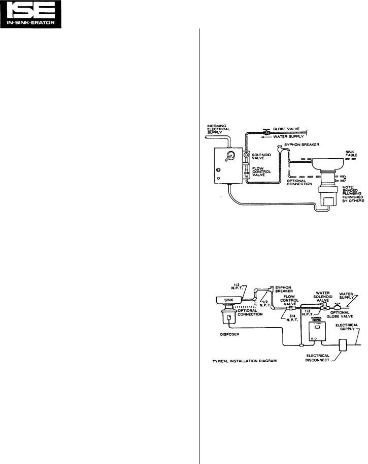
PLUMBING INSTALLATION |
|
|
|
|
|
|
|
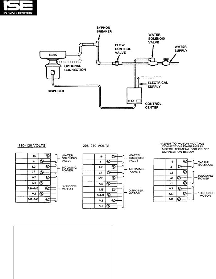
The following plumbing installation diagrams are included to |
|
|
|
|
|
|
|
illustrate the plumbing connections of a typical installation. |
|
|
|
|
|
|
|
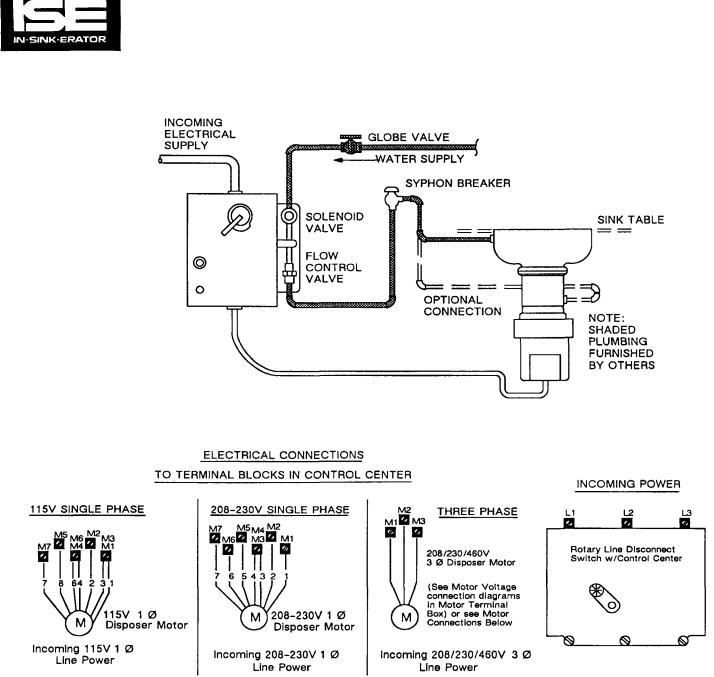
Figure 5-1 shows an installation for a control center with an |
|
|
|
|
|
|
|
enclosure-mounted solenoid valve (models CC-101A and |
Figure |
5-1. |
Plumbing |
Connection |
Diagram, |
Typical |
|
CC-101B). Figure 5-2 shows an installation with a remote- |
|
|
Installation (Enclosure-Mount Solenoid |
||||
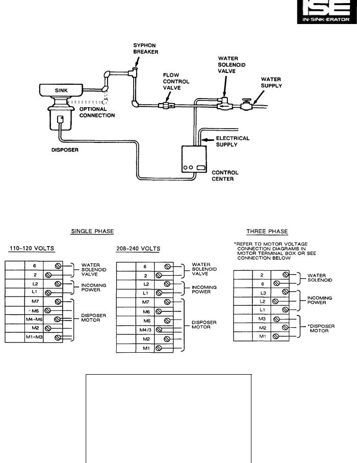
mount solenoid valve (all other models). |
|
|
Valve). |
|
|
|
|
The solenoid valve and flow control valve are each marked |
|
|
|
|
|
|
|
with arrows showing the proper water flow direction. Both |
|
|
|
|
|
|
|
valves must be installed so that the water flows through them |
|
|
|
|
|
|
|
in the correct direction or the valves will not work properly. |
|
|
|
|
|
|
|
Note that in all installations a syphon breaker (vacuum |
|
|
|
|
|
|
|
breaker) must be installed above the sink flood plane per local |
|
|
|
|
|
|
|
plumbing code. |
|
|
|
|
|
|
|
GENERAL ELECTRICAL INFORMATION |
|
|
|
|
|
|
|
IN-SINK-ERATOR Commercial Disposer Control Centers are |
|
|
|
|
|
|
|
shipped from the factory wired for a specific voltage and |
|
|
|
|
|
|
|
phase. Please refer to the Control Center wiring diagrams in |
|
|
|
|
|
|
|
this manual for the correct connections. (Disposer motor |
|
|
|
|
|
|
|
connections will depend upon the operating voltage and |
|
|
|
|
|
|
|
phase of the disposer.) |
|
|
|
|
|
|
|
|
Figure |
5-2. Plumbing |
Connection |
Diagram, |
Typi cal |
||
|
|
|
Installation (Remote-Mount Solenoid |
||||
|
|
|
Valve). |
|
|
|
|
3-1
SECTION 3 GENERAL INFORMATION (Cont'd)
FEATURES
All CC-101 series Commercial Disposer Control Centers have the following features:
Automatic Reversing Action — Automatically reverses the disposer motor each time it is started to double the life of the disposer grinding shredders.
Built-in Magnetic Starter — Automatically disengages electric power to disposer if power loss occurs. Disposer must be restarted.
Post Water Flush — Adjustable time delay relay automatically permits water to flush sewer lines clear after disposer has
been turned off, eliminating sewer clogging.
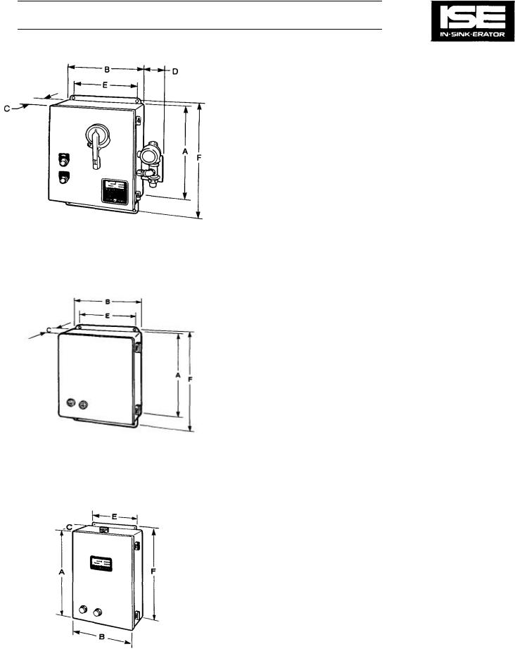
Figure 4-1. CC-101B
DIMENSIONS
Models CC-101 A and CC-101B
Length (A) |
14" |
|
Width (B) |
12" |
|
Depth (C) |
6" |
|
Width (D) |
3-1/2" |
|
5/16" Bolt Holes, Center to Center (E) |
10" |
|
5/16" Bolt Holes, Center to Center (F) |
14-11/16" |
|
Models CC-101C. CC-101D, and CC-101E
Length (A) |
14" |
|
Width (B) |
12" |
|
Depth (C) |
6" |
|
Figure 4-2. CC-101E |
|
10" |
5/16" Bolt Holes, Center to Center (E) |
||
5/16" Bolt Holes, Center to Center (F) |
14-11/16" |
|
Other Features:
—Main flow control valve and solenoid valve mounted elsewhere in water line
Model CC-101G
Length (A) |
15" |
|
Width (B) |
10" |
|
Depth (C) |
6" |
|
5/16" Bolt Holes, Center to Center (E) |
8" |
|
5/16" Bolt Holes, Center to Center (F) |
15-5/8" |
|
Figure 4-3. CC-101G
3-2

WIRING DIAGRAMS |
SECTION 4 |
The standard disposer motor voltages are 115/208/230 volts for single phase electrical power and 208/230/460 volts for three phase electrical power.
NOTE
Three phase contactors require three sets of contacts to carry line voltage to the disposer, while single phase contactors require four Circuitry and parts function on all control centers are identified within their respective models. This applies to all component parts controlled by or on the secondary voltage side of the transformer, whether it is a 1 phase or 3 phase control center.
The wiring (circuitry) to the line voltage connections on the Reversing contactors are identical on all 3 phase (only) contactors. The wiring (circuitry) to the line voltage connections on the Reversing contactors are identical on all 1 phase (only) contactors.
sets. Two identical contactors are utilized in every control center to perform the function of reversing the disposer motor rotation.
Therefore, the wiring diagrams in this section (Figs. 4-12 through 4- 19) show 3 phase contactors but can be used to diagnose or trace circuitry for 1 phase or 3 phase control centers, keeping in mind that only the contactors are different from 1 phase to 3 phase. Refer to Figs. 4-10 and 4-11 for 1 phase contactor connections.
CAUTION
All electrical connections must conform to local codes. Be certain that all IN-SINK-ERATOR disposers and control centers are carefully and permanently grounded.
ELECTRICAL INSTALLATION
WARNING
BEFORE ANY ELECTRICAL WORK IS PERFORMED, REMOVE LINE
POWER FROM THE DISPOSER CONTROL CENTER BY TURNING OFF
THE CIRCUIT BREAKER. USE A VOLTMETER OR CIRCUIT TESTER TO
ENSURE THAT POWER IS OFF BEFORE PROCEEDING.
CAUTION The control center and disposer motor voltage and phase must be the same as the electrical supply. Check name -plates on both units for ratings.
All connections must conform to local codes. Ground the disposer control center, the disposer, and all control boxes.
The following wiring diagrams are included to illustrate the electrical connections for each standard model of disposer control center and disposer motor. For each standard model of disposer control center, wiring diagrams are shown to illustrate the most typical configurations. The wiring diagrams include motor connections. Since various options can be custom ordered for a control enter, the wiring diagrams for a particular model of control center do not reflect every possible option. Additional wiring diagrams illustrating various special (nonstandard) configurations of each model are provided in section 10 of this manual.
4-1
SECTION 4 |
WIRING DIAGRAMS (Cont'd) |
|
|
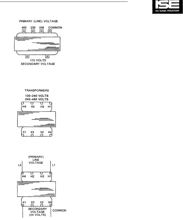
TRANSFORMER CONNECTIONS FOR
CONTROL CENTERS WITH 115 V CONTROL
CIRCUIT
Power lines carry line voltage to the primary terminals (also called "taps") of the transformer. Line L2 is connected to the common (ground) tap with Line L1 connected to the tap coinciding with the line voltage.
The secondary taps on these transformers will always supply 115 V ac to the load. This secondary voltage operates the component parts in the control circuit. These transformers are rated at 100 VA (Volt/Amperes), and can be used for any 208 V/230 V/460 V incoming line. See Figure 4-3.
TRANSFORMER CONNECTIONS FOR
Figure 4-3. 115 V Transformer Taps. CONTROL CENTERS WITH 24 V CONTROL CIRCUITS
All control centers with 24 V secondary voltage require one of two transformers. They appear identical. The specification decal on the transformers will show 120 - 240 V or 240 -480 V (connections for line voltage). There is no reference to 208 V, but it is to be understood that 208 V connections will be the same as 240 V. Whenever the recommended transformer is used wiring diagrams furnished with the Control Center or in this manual apply.
Both 24 V secondary tap transformers can be used with 240 or 208 V inputs, but the terminal connections will change and Control Center wiring diagrams may not necessarily apply. Whenever in doubt, refer to and use the connections shown on the transformer specification decal. Connections for input (primary) and output (secondary) voltages are the same in all cases. See Figure 4-4 for connections.
RATED AT 100 VA
Figure 4-4. 24 V Transformer Taps.
4-2

WIRING DIAGRAMS (Cont'd) |
SECTION 4 |
Terminal Connections
Transformer tap connections vary and are made in accordance with the applied line voltage. A conductive connection strap is normally used but 12 ga. wire can be substituted (see Fig. 4-5).
Connections
Shown are the standard connections when the recommended transformer is used. Refer to the illustrated parts list for specific Control Centers. The voltage and phase of the Control Center must be known. Secondary voltage for Figs. 4-5 through 4-8 is 24 V.
Figure 4-5. 115 V, 1 Phase.
4-3
WIRING DIAGRAMS (Cont'd) |
SECTION 4 |
|
|
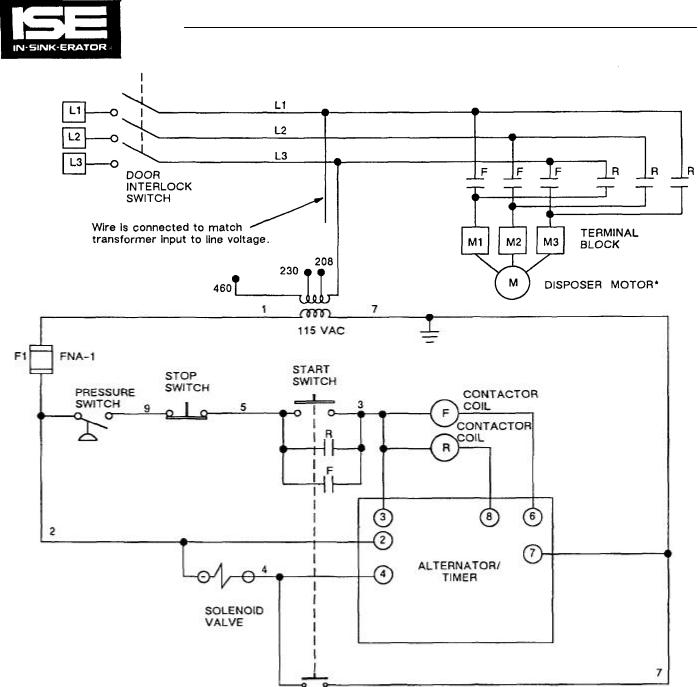
*SEE WIRING DIAGRAM IN DISPOSER TERMINAL BOX FOR PROPER CONNECTIONS OR FIG. 5-2.
Figure 4-12. Model CC-101A Wiring Diagram.
4-7
SECTION 4 |
WIRING DIAGRAMS (Cont'd) |
|
|
*SEE WIRING DIAGRAM IN DISPOSER TERMINAL BOX FOR PROPER CONNECTIONS OR FIG. 5-2.
Figure 4-13. Model CC-101A Wiring Diagram (with Contactor Interlocks).
4-8
WIRING DIAGRAMS (Cont'd) |
SECTION 4 |
|
|
*SEE WIRING DIAGRAM IN DISPOSER TERMINAL BOX FOR PROPER CONNECTIONS OR FIG. 5-2.
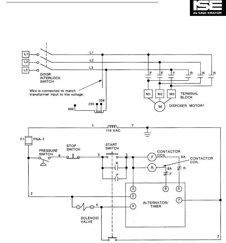
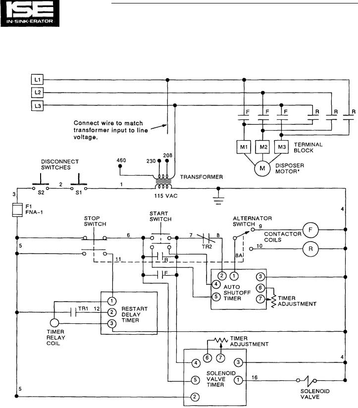
Figure 4-14. Model CC-101B Wiring Diagram.
4-9
SECTION 4 |
WIRING DIAGRAMS (Cont'd) |
|
|
*SEE WIRING DIAGRAM IN DISPOSER TERMINAL BOX FOR PROPER CONNECTIONS OR FIG. 5-2.
Figure 4-15. Model CC-101B Wiring Diagram (with Auto-Shutoff Timer).
4-10
WIRING DIAGRAMS (Cont'd) |
SECTION 4 |
|
|
*SEE WIRING DIAGRAM IN DISPOSER TERMINAL BOX FOR PROPER CONNECTIONS OR FIG. 5-5.
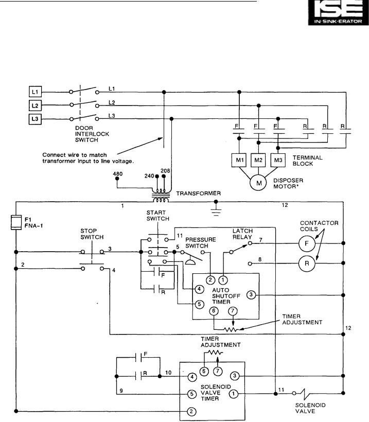
Figure 4-16. Modal CC-101C and CC-101D Wiring Diagram.
4-11
SECTION 4 |
WIRING DIAGRAMS (Cont'd) |
*SEE WIRING DIAGRAM IN DISPOSER TERMINAL BOX FOR PROPER CONNECTIONS OR FIG. 5-7.
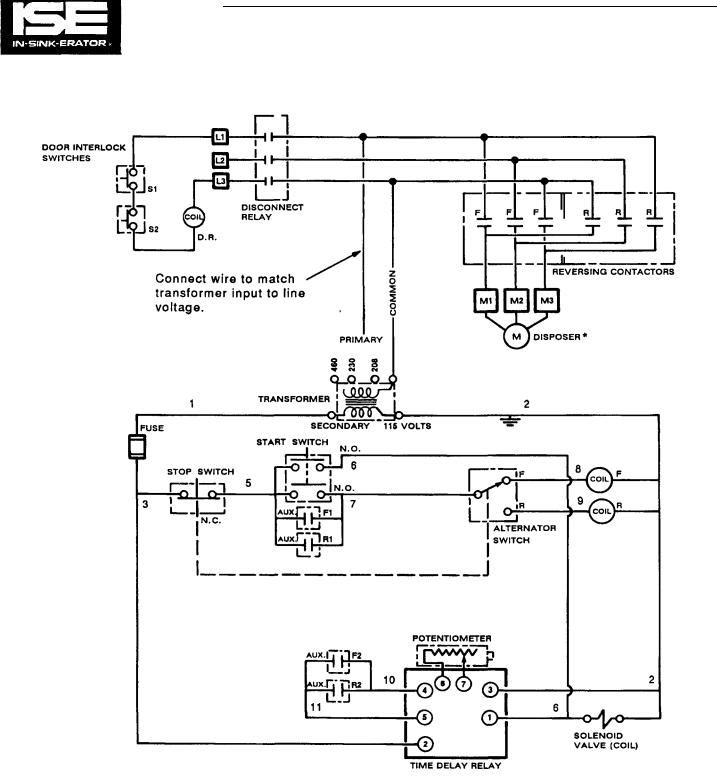
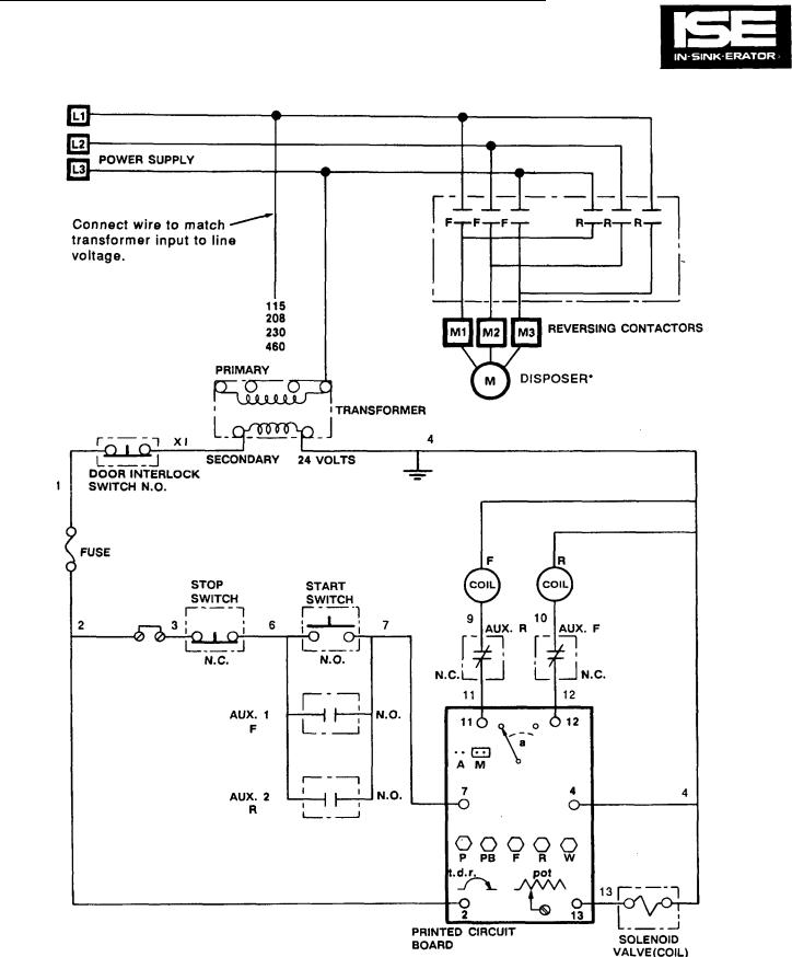
Figure 4-17. Model CC-101E Wiring Diagram.
4-12
WIRING DIAGRAMS (Cont'd) |
SECTION 4 |
|
|
•SEE WIRING DIAGRAM IN DISPOSER TERMINAL BOX FOR PROPER CONNECTIONS OR FIG. 5-7.
Figure 4-18. Model CC-101E Wiring Diagram (with Auto-Shutoff Timer).
4-13
SECTION 4 |
WIRING DIAGRAMS (Cont'd) |
•SEE WIRING DIAGRAM IN DISPOSER TERMINAL BOX FOR PROPER CONNECTIONS OR FIG. 5-9.
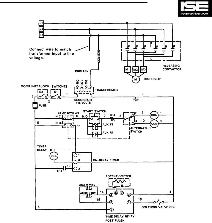
Figure 4-19. Model CC-101G Wiring Diagram.
4-14
PLUMBING, MOTOR AND LINE VOLTAGE |
SECTION 5 |
|
CONNECTIONS |
||
|
Figure 5-1. CC-101A & B General Layout.
Figure 5-2. Electrical Connections
For CC-101A & CC-101B. |
|
|
|
MOTOR CONNECTIONS FOR |
|
|
|
208/230 VOLT-3 0 |
460 VOLT-3 0 |
7 & 1 ———— M1 |
1 —————— M1 |
8 & 2 ———— M2 |
2 —————— M2 |
3 & 9 ———— M3 |
3 —————— M3 |
10 & 4 ———— TT |
4 & 7 ———— TT |
5 & 1 ———— TT |
5 & 8 ———— TT |
12 & 6 ———— TT |
3 & 9 ———— TT |
|
10 - TS |
TS = TAPE SEPARATELY |
11 - TS |
TT = TIE TOGETHER |
12 - TS |
NOTE: OLD 208 VOLT 3 0 MOTORS HAD ONLY 3 LEAD WIRES ATTACHED TO TERMINAL BLOCK M1, M2 & M3.
Figure 5-3. Rotary Disconnect
For CC-101A & CC-101B.
These control centers have rotary line disconnect switches directly connected to the incoming line.
The terminal blocks accommodate the motor connections.
5-1
SECTION 5
PLUMBING, MOTOR AND LINE VOLTAGE
CONNECTIONS (Cont'd)
Figure 5-4. CC-101C & D General Layout.
ELECTRICAL CONNECTIONS TO TERMINAL
BLOCK IN CONTROL CENTER
MOTOR CONNECTIONS FOR
|
20B/230 VOLT-3 0 |
460 VOLT-3 0 |
|
|
|
|
|
7 |
& 1 |
———— M1 |
1 —————— M1 |
8 |
& 2 |
———— M2 |
2 —————— M2 |
3 |
& 9 |
———— M3 |
3 —————— M3 |
10 & 4 ———— TT |
4 & 7 ———— TT |
||
5 |
& 1 |
———— TT |
5 & 8 ———— TT |
12 & 6 ———— TT |
3 & 9 ———— TT |
||
|
|
|
10 - TS |
TS = TAPE SEPARATELY |
11 - TS |
||
TT = TIE TOGETHER |
12 - TS |
||
Figure 5-5. Electrical Connections For CC-101C & CC-101D.
5-2
PLUMBING, MOTOR AND LINE VOLTAGE
CONNECTIONS (Cont'd) |
SECTION 5 |
|
Figure 5-6. CC-101E General Layout.
ELECTRICAL CONNECTIONS TO TERMINAL
BLOCK IN CONTROL CENTER
SINGLE PHASE |
THREE PHASE |
MOTOR CONNECTIONS FOR
|
208/230 VOLT-3 0 |
460 VOLT-3 0 |
|
|
|
|
|
7 |
& 1 |
——— M1 |
1 —————— M1 |
8 |
& 2 |
———— M2 |
2 —————— M2 |
3 |
& 9 |
———— M3 |
3 —————— M3 |
10 & 4 ———— TT |
4 & 7 ———— TT |
||
5 |
& 1 |
———— TT |
5 & 8 ———— TT |
12 & 6 ———— TT |
3 & 9 ———— TT |
||
|
|
|
10 - TS |
TS = TAPE SEPARATELY |
11 - TS |
||
TT = TIE TOGETHER |
12 - TS |
||
|
|
|
|
Figure 5-7. Electrical Connections For CC-101E.
5-3

SECTION 5
PLUMBING, MOTOR AND LINE VOLTAGE
CONNECTIONS (Cont'd)
Figure 5-8. CC-101G General Layout.
MOTOR CONNECTIONS FOR
208/230 VOLT-3 0 |
|
|
460 VOLT-3 0 |
|
|
|
|
|
|
7 & 1 |
———— M1 |
1 |
—————— M1 |
|
8 & 2 |
———— M2 |
2 |
—————— M2 |
|
3 & 9 |
———— M3 |
3 |
—————— M3 |
|
10 & 4 ———— TT |
4 |
&7 ———— TT |
||
5 & 1 |
——— TT |
5 & 8 ———— TT |
||
12 & 6 ———— TT |
3 & 9 ———— TT |
|||
|
|
10 |
- TS |
|
TS = TAPE SEPARATELY |
11 |
- TS |
||
TT = TIE TOGETHER |
12 |
- TS |
||
|
|
|
|
|
Figure 5-9. Electrical Connections For CC-101G.
5-4
SUBPANEL REMOVAL AND REPLACEMENT |
SECTION 6 |
GENERAL
This section provides the information required for the removal and replacement of the subpanel in the disposer control center enclosure. The subpanel is the flat piece of sheet metal inside the enclosure that most of the components are mounted on. Most components are secured with screws and can be changed without removing the subpanel. However, a few components are secured with screws to a nut on the back of the subpanel and require that the panel be removed to remove the component. Also, it is sometimes necessary to remove the subpanel to retrieve lost fasteners.
Differences between control center models sometimes require slight differences in the procedures. The changes are described when necessary.
REMOVAL PROCEDURE
WARNING
BEFORE PERFORMING ANY REPAIRS ON THE
DISPOSER OR THE DISPOSER CONTROL CENTER, BE
SURE TO TURN OFF THE MAIN POWER AT THE
DISCONNECT, CIRCUIT BREAKER OR FUSE BOX. LABEL
AND LOCK THE CIRCUIT OPEN. USE A METER OR
ELECTRICAL TESTER TO ENSURE THAT POWER IS OFF
BEFORE PERFORMING ANY REPAIRS.
1.Turn off power line to disposer control center. Label and lock the circuit open.
2.For units equipped with door interlock switch, turn door interlock switch to OFF position.
3.Loosen screws securing enclosure door clamps and open door.
NOTE
Before disconnecting any wire, write down its location. You will need to refer to It when reassembling the disposer control center.
NOTE
Some units have plastic safety shields covering the terminals of some components. On units so equipped, remove the shield
(s)before disconnecting wires from those components.
4.Disconnect power line wires from contactor or disconnect relay.
5.Disconnect and separately insulate disposer motor
wires from terminal block.
6.Disconnect wires from start switch terminals.
7.Disconnect wires from stop switch terminals.
8.On units so equipped, cut cable tie securing stop
switch/start switch wire harness to enclosure.
9.Disconnect solenoid valve wires from terminal block.
10.On units equipped with pressure switch, disconnect pressure switch wires.
11.On units equipped with disconnect switch (es), disconnect wires from disconnect switch terminals.
6-1

SUBPANEL REMOVAL AND
SECTION 6 |
REPLACEMENT (Cont'd) |
|
12. Remove screws securing panel to enclosure.
13. Carefully remove panel from enclosure. It may be necessary to tilt the panel somewhat to remove it from the enclosure.
NOTE
Some units have a plastic safety shield over the terminals of the door interlock switch or disconnect contactor. On units so equipped, the safety shield must be removed before the power line wires can be disconnected.
REASSEMBLY PROCEDURE
WARNING
BEFORE PERFORMING ANY REPAIRS ON THE
DISPOSER OR THE DISPOSER CONTROL CENTER. BE
SURE TO TURN OFF THE MAIN POWER AT THE
DISCONNECT, CIRCUIT BREAKER OR FUSE BOX.
LABEL AND LOCK THE CIRCUIT OPEN. USE A METER
OR ELECTRICAL TESTER TO ENSURE THAT POWER IS
OFF BEFORE PERFORMING ANY REPAIRS.
1. Make sure power line to disposer control center is still turned off.
2. Insert panel in enclosure and position panel so that mounting holes in panel are aligned with standoffs (mounting posts) in enclosure.
3. Secure panel to enclosure with 4 screws.
4. Connect solenoid valve wires.
5. On units equipped with a pressure switch, connect pressure switch wires.
6. On units equipped with disconnect switch (es), connect wires to disconnect switch terminals.
7. If cable tie was cut during disassembly procedure, replace cable tie.
8. Connect wires to start switch terminals.
9. Connect wires to stop switch terminals.
10. Connect disposer motor wires.
11. Connect power line wires.
12. On units equipped with plastic safety shields, replace the safety shield over the terminals.
13. Close and secure enclosure door.
6-2
COMPONENT DESCRIPTION |
SECTION 7 |
GENERAL
This section provides information on the function of the component parts of the control center. Photographs of the individual components are provided, with a description accompanying each one. For some components, more than one photograph is provided in order to illustrate minor component changes from one model to the next. This section also calls out the location of each component on the schematic diagram.
Note that no one model of disposer control center contains all the components listed in this section. The components used in a particular control center can be determined by looking at the wiring diagram on the inside of the control center enclosure door.
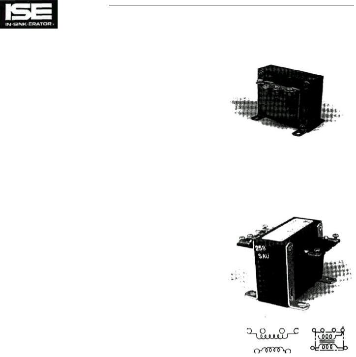
Transformer
The transformer steps down the higher voltage from the power line to a relatively low 115 volts (24 volts for some models). This lower voltage is used for control purposes to power the controlling components, which may include a reverser/timer, a latch relay coil, a contactor coil, a solenoid valve, a solenoid valve timer, a restart delay timer, a timer relay coil, a control circuit board, and an auto shutoff timer.
Line voltage is applied to the primary winding (the top winding of the transformer as shown on the wiring diagram), and the control voltage (115 or 24 volts) is taken from the secondary winding (the bottom winding). The transformer has several different input connections so that it can be used with different line voltages.
Figure 7-1. Transformer.
7-1

SECTION 7 COMPONENT DESCRIPTION (Cont'd)
Fuse
The fuse, designated F1 on the wiring diagrams in this manual, provides circuit protection in the event of a short circuit or other electrical problem in the control center. If too much current is used by the any component in the control center, the fuse will blow, opening the circuit. This fuse does not protect the disposer motor from excessive current; the disposer motor is protected by the circuit breaker or fuse in the line that supplies power to it or by the overload protector or the disposer motor.
NOTE
On the wiring diagrams Inside the enclosure door, some models designate the fuse by Its F1 reference designation;
other models designate It only by its fuse type, e.g. FNA 1 or FHA 2.
Door Interlock Switch (Line Disconnect)
Figure 7-2. Fuse.
The door interlock switch is a safety device that combines a disconnect switch with a mechanical door latch. They are connected together by an "operating rod" that is fastened to the interlock switch. The door interlock switch must be turned off to open the control center door. Turning the switch off disconnects the power line from the disposer motor and from the transformer that supplies power to the control circuits in the control center. This is done as a safety precaution. However, line voltage is still present on the line terminals of the door interlock switch.
Figure 7-3. Door Interlock Switch.
7-2
COMPONENT DESCRIPTION (Cont'd)
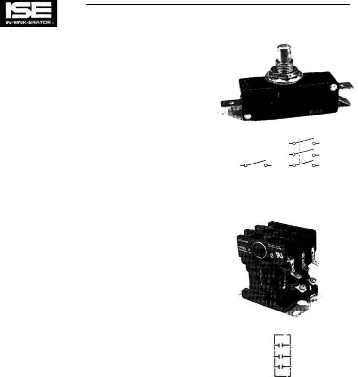
Disconnect Switch
Control centers that do not have a door interlock switch have one or two disconnect switches mounted at the top of the control center enclosure. The switch (es) are positioned so that when the control center door is closed, the switch plunger(s) are pushed in, closing the switch contacts. Disconnect switch contacts are wired in series. When the control center door is opened, the switch contacts open and the control voltage is turned off, either directly by the disconnect switch or indirectly by a disconnect relay on units so equipped. This turns off line voltage to the disposer control center (for units with two disconnect switches, only one disconnect switch has to be open to disconnect the control voltage). However, line voltage is still present at the power line terminals of some components (refer to the appropriate wiring diagram to determine which terminals remain live for any particular model).
Disconnect Relay (Line Disconnect)
Some models of disposer control center have a disconnect relay that works in conjunction with disconnect switches. The disconnect relay supplies line power to the disposer control center. The disconnect relay coil is powered directly from the power lines (line voltage). Power to the disconnect relay coil is controlled by the disconnect switches. If either switch opens (the control center door is opened), the disconnect relay coil is turned off. This opens the relay, disconnecting line power to the disposer control center. However, line voltage is still present on the power line terminals of the disconnect relay even when the contactor is open.
SECTION 7
Figure 7-4. Disconnect Switch.
Figure 7-5. Disconnect Relay.
7-3
|
SECTION 7 |
COMPONENT DESCRIPTION (Cont'd) |
|
|
|
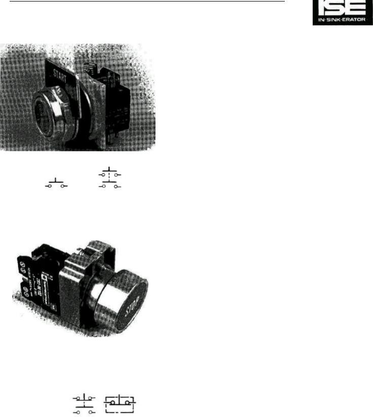
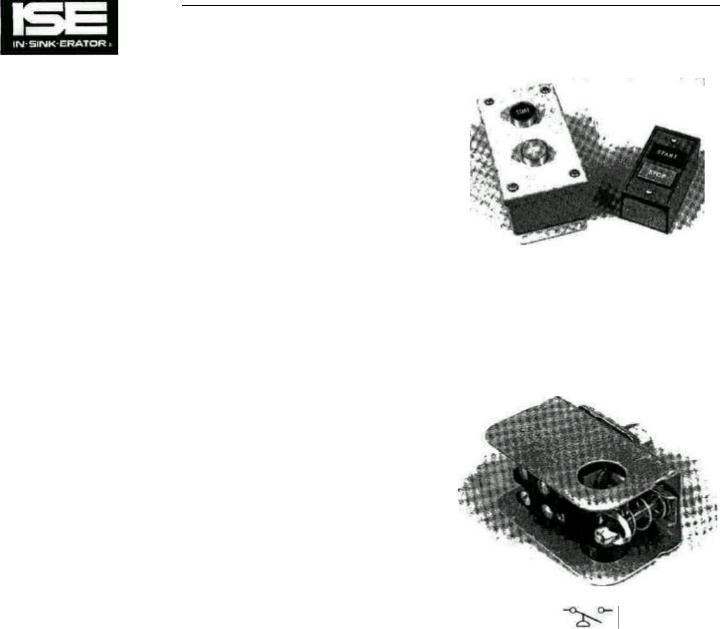
START Switch |
|
|
|
The START switch has one or more sets of contacts, depending upon |
|
|
|
the model. When the START switch is pressed, all the contacts close. |
|
|
|
Depending upon the model, the contacts send power to different |
|
|
|
devices such as the contactor coil, the solenoid valve, the control |
|
|
|
circuit board, and the auto shutoff timer. All functions required to start |
|
|
|
the disposer are switched by the START switch contacts. |
|
|
|
NOTE |
|
|
|
For all models, the START and STOP switches are each com- |
|
|
|
posed of a mechanical pushbutton connected to one or two |
|
|
|
detachable sets of electrical contacts that open and close as |
|
|
|
the pushbutton moves In and out. However, for the operational |
|
|
|
description, the STOP and START switches are treated as |
|
|
|
single components rather than as assemblies. |
|
|
|
STOP Switch |
|
|
|
The STOP switch has one or more sets of contacts, depending |
|
|
|
upon the model. When the STOP switch is pressed the |
|
|
|
contacts open or close, depending upon whether they are |
|
|
|
normally open. or normally closed. One set of contacts opens |
|
|
|
to interrupt power to the contactor coil (either directly or via the |
|
|
|
control circuit board). Other contacts close to activate the |
|
Figure 7-6. START Switch. |
alternator/timer, latch relay, or the restart delay timer. |
||
|
|
||
|
|
NOTE |
|
|
|
The start and stop switches are momentary contact pushbut- |
|
|
|
ton switches. Once pressed in, they will return to their original |
|
|
|
position when released. |
|
Figure 7-7. STOP Switch.
7-4
COMPONENT DESCRIPTION (Cont'd) |
SECTION 7 |
Remote Control Station
This is a START switch and a STOP switch that can be mounted at a distance from the control center, and are the same type and design of those on the control center. The remote START switch contacts are connected in parallel with the control center START switch contacts. The remote STOP switch contacts are connected in series or parallel with the control center STOP switch contacts, depending upon the model. (Refer to the appropriate wiring diagram.)
Pressure Switch
The pressure switch prevents the disposer motor from operating if the water pressure falls below approximately 15 p.s.i. If pressure drops below this point, the pressure switch opens, interrupting power to the component parts and shuts down the disposer. The START switch must be pressed to restart the disposer. The pressure switch acts in the same manner as a STOP switch.
Figure 7-8. Remote Control Station.
Figure 7-9. Pressure Switch.
7-5
SECTION 7 COMPONENT DESCRIPTION (Cont'd)
|
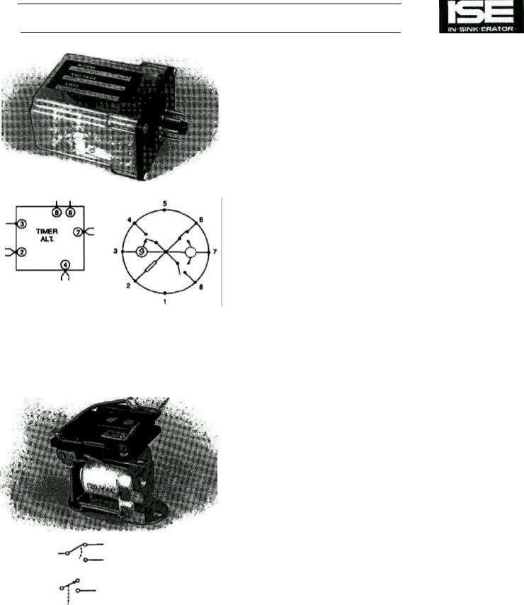
Reverser/Timer |
|
|
The reverser/timer performs two different functions for the |
|
|
disposer control center. It switches between the F and the R |
|
|
contactor coils with every START/STOP cycle. This provides |
|
|
the automatic reversing action for the disposer motor. It also |
|
|
controls the water flow timing cycle. When the STOP switch is |
|
|
pressed the reverser/timer begins the 5-minute water flow |
|
|
timing cycle; it maintains power to the solenoid valve until the |
|
|
cycle ends. Terminal 2 is the power input, terminal 7 is ground |
|
|
(common), terminal 4 is the output that drives the solenoid |
|
|
valve, and terminal 3 senses when each START/ STOP cycle |
|
|
begins and ends. Terminals 6 and 8 connect to the F (forward) |
|
|
and R (reverse) contactor coils respectively. Note that when the |
|
|
START switch is pressed, the reverser/ timer connects the F or |
|
|
R contactor coil internally to pin 7 to turn the contactor coil on. |
|
|
Latch Relay (Reversing Relay) |
|
|
The latch relay performs the automatic reversing of the dis- |
|
|
poser motor. This relay toggles ("flip-flops") or switches |
|
|
between its two sets of contacts once per START/STOP cycle. |
|
|
In one position, the latch relay directs voltage to the F (forward) |
|
|
contactor coil, causing the disposer motor to run in the forward |
|
|
direction. In the other position, the latch relay directs voltage to |
|
|
the R (reverse) contactor coil, causing the motor to run in the |
|
Figure 7-10. Reverser/Timer and Socket. |
reverse direction. The latch relay changes position every time |
|
the STOP switch is pressed. |
||
|
Figure 7-11. Latch Relay.
7-6
COMPONENT DESCRIPTION (Cont'd) |
SECTION 7 |
Alternator Switch (Reversing)
The alternator switch provides auto-reversing action for the disposer motor by alternately selecting between its two outputs every START/STOP cycle. The alternator switch is mechanically linked with the STOP switch so that every time the STOP switch is pressed, the alternator switch changes from one output to the other. One output is connected to the F contactor coil; the other is connected to the R contactor coil.
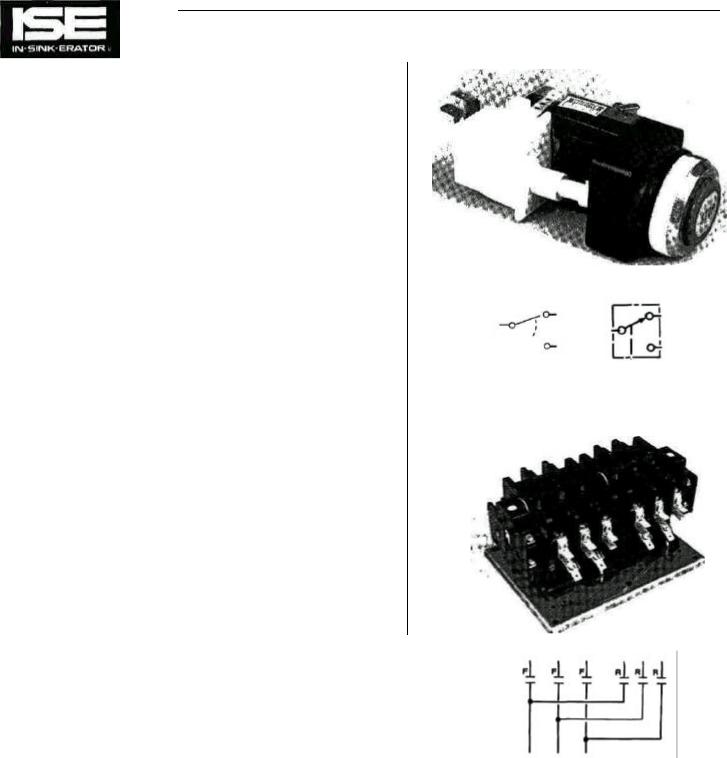
Contactors (Reversing Contactors)
Two contactors, F (forward) and R (reverse), direct line voltage to the disposer motor. They are either mounted separately or on a mutual mounting plate. One connects the disposer motor windings to run the disposer in the forward direction. The other connects them to run in the reverse direction. Depending upon the model of disposer control center, selection of the contactors is controlled by the reverser/ timer, reversing switch, latch relay, or control circuit board. This description does not include the auxiliary contacts or auxiliary contact microswitches mounted to the reversing contactor.
When power is applied to one of the contactor coils, all of the contacts associated with that coil close. They open again when power is removed from the coil. Note that only one contactor, F or R, can be energized at a time. All the F contacts shown on the wiring diagram close when the F contactor coil is energized. All the R contacts close when the R coil is energized. When the contactor pulls down engaging the contacts carrying power to the motor, it also activates the auxiliary contacts or auxiliary contact microswitches.
Since the application of the contacts differs from one model of disposer control center to the next, it is necessary to refer to the wiring diagram for each model to determine their functions.
Figure 7-12. Alternator Switch (Is fastened to the STOP switch).
Figure 7-13. Contactors.
7-7
SECTION 7 COMPONENT DESCRIPTION (Cont'd)
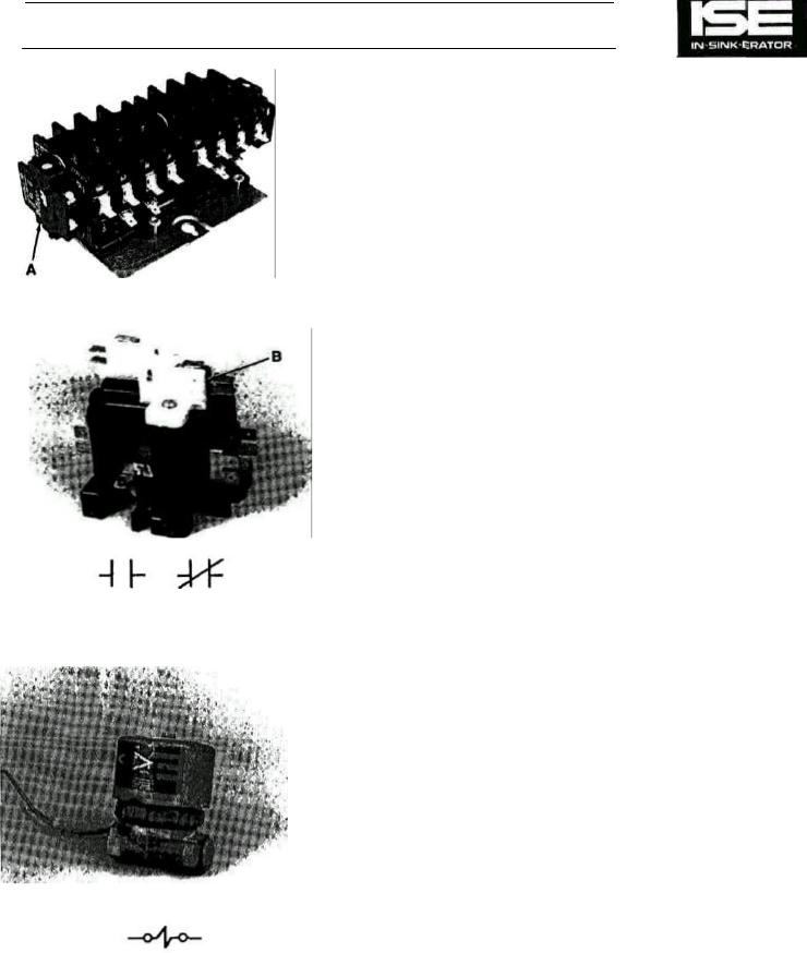
Auxiliary Contacts
Auxiliary contacts are additional sets of contacts (block or microswitches) mounted to and are activated in unison with the mechanical action of the reversing contactors.
Auxiliary contact blocks are mounted to the end of the reversing contactor. See Fig. 7-14 (A).
Auxiliary contact microswitches are mounted to the top of the reversing contactor. See Fig. 7-14 (B).
Auxiliary contacts may contain one or two sets of contacts which may have any combination of N.O. and/or N.C.
They are used in the control circuit to:
•Bypass the start button (switch) after the unit is started and the start button is released, maintaining power to the control circuit.
•Activate power to the "F" or "R" coil in the reversing contactor.
•Engage the time delay relay controlling the solenoid
valve.
•"Lockout" the reversing contactor coil not engaged preventing it from being activated.
•Maintain power to the time delay relay holding the solenoid valve engaged after the stop button is pressed and the disposer motor stops.
The model of the control center determines the type, the number of and the function of the auxiliary contacts. Review the respective wiring diagram.
Solenoid Valve
The solenoid valve is an electrically-controlled water valve. The valve opens when power is applied to the solenoid valve coil, allowing water to flow to the disposer. When power to the coil is removed, the valve shuts off the water flow. The solenoid valve is powered by the transformer in the disposer control center,
Figure 7-14. Auxiliary Contacts. and is controlled by the reverser/timer, the time delay relay, or a printed circuit board.
The solenoid valve must be installed with its arrow pointing downstream or erratic water flow will occur.
Figure 7-15. Solenoid Valve.
7-8
 Loading...