

Insignia NS-R5101HD - AV Receiver User Manual

User Guide
5.1 Surround Sound Receiver
NS-R5101HD

Contents
Important safety instructions . . . . . . . . . . . . . . . . . . . . . . . . . . . . . . . . . . . . .1
Introduction . . . . . . . . . . . . . . . . . . . . . . . . . . . . . . . . . . . . . . . . . . . . . . . . . . . . .3
Features . . . . . . . . . . . . . . . . . . . . . . . . . . . . . . . . . . . . . . . . . . . . . . . . . . . . . . . . .3
Package contents . . . . . . . . . . . . . . . . . . . . . . . . . . . . . . . . . . . . . . . . . . . . . . . . . . . 3
Front . . . . . . . . . . . . . . . . . . . . . . . . . . . . . . . . . . . . . . . . . . . . . . . . . . . . . . . . . . . . . . . . 3
Display . . . . . . . . . . . . . . . . . . . . . . . . . . . . . . . . . . . . . . . . . . . . . . . . . . . . . . . . . . . . . . 3
Back . . . . . . . . . . . . . . . . . . . . . . . . . . . . . . . . . . . . . . . . . . . . . . . . . . . . . . . . . . . . . . . . 4
Remote control . . . . . . . . . . . . . . . . . . . . . . . . . . . . . . . . . . . . . . . . . . . . . . . . . . . . . . 5
Using the remote control . . . . . . . . . . . . . . . . . . . . . . . . . . . . . . . . . . . . . . . . .5
Installing remote control batteries . . . . . . . . . . . . . . . . . . . . . . . . . . . . . . . . . . . 5
Aiming the remote control . . . . . . . . . . . . . . . . . . . . . . . . . . . . . . . . . . . . . . . . . . 6
Making connections . . . . . . . . . . . . . . . . . . . . . . . . . . . . . . . . . . . . . . . . . . . . . .6
Connecting an FM antenna . . . . . . . . . . . . . . . . . . . . . . . . . . . . . . . . . . . . . . . . . . 6
Connecting an AM antenna . . . . . . . . . . . . . . . . . . . . . . . . . . . . . . . . . . . . . . . . . . 7
About video connections . . . . . . . . . . . . . . . . . . . . . . . . . . . . . . . . . . . . . . . . . . . . 7
Connecting a DVD recorder . . . . . . . . . . . . . . . . . . . . . . . . . . . . . . . . . . . . . . . . . . 7
Connecting a VCR . . . . . . . . . . . . . . . . . . . . . . . . . . . . . . . . . . . . . . . . . . . . . . . . . . . 8
Connecting a Blu-ray Disc player or DVD player . . . . . . . . . . . . . . . . . . . . . . . 8
Connecting a TV . . . . . . . . . . . . . . . . . . . . . . . . . . . . . . . . . . . . . . . . . . . . . . . . . . . . . 9
Connecting a device to the front AV jacks . . . . . . . . . . . . . . . . . . . . . . . . . . . 10
Connecting a CD player . . . . . . . . . . . . . . . . . . . . . . . . . . . . . . . . . . . . . . . . . . . . 10
Connecting digital audio . . . . . . . . . . . . . . . . . . . . . . . . . . . . . . . . . . . . . . . . . . . 10
Connecting headphones . . . . . . . . . . . . . . . . . . . . . . . . . . . . . . . . . . . . . . . . . . . 11
Connecting speakers . . . . . . . . . . . . . . . . . . . . . . . . . . . . . . . . . . . . . . . . . . . . . . . 11
Connecting an IR receiver . . . . . . . . . . . . . . . . . . . . . . . . . . . . . . . . . . . . . . . . . . . 13
Adjusting the speakers . . . . . . . . . . . . . . . . . . . . . . . . . . . . . . . . . . . . . . . . . 13
Selecting speaker type . . . . . . . . . . . . . . . . . . . . . . . . . . . . . . . . . . . . . . . . . . . . . 13
Selecting the crossover frequency . . . . . . . . . . . . . . . . . . . . . . . . . . . . . . . . . . 14
Adjusting speaker output levels . . . . . . . . . . . . . . . . . . . . . . . . . . . . . . . . . . . . . 14
Selecting the speaker distance . . . . . . . . . . . . . . . . . . . . . . . . . . . . . . . . . . . . . . 15
Setting the listening environment (ROOM EQ) . . . . . . . . . . . . . . . . . . . . . . . 16
Understanding the basics . . . . . . . . . . . . . . . . . . . . . . . . . . . . . . . . . . . . . . 17
Turning your receiver on or off . . . . . . . . . . . . . . . . . . . . . . . . . . . . . . . . . . . . . . 17
Selecting the input source . . . . . . . . . . . . . . . . . . . . . . . . . . . . . . . . . . . . . . . . . . 17
Adjusting the volume . . . . . . . . . . . . . . . . . . . . . . . . . . . . . . . . . . . . . . . . . . . . . . 17
Adjusting the bass and treble . . . . . . . . . . . . . . . . . . . . . . . . . . . . . . . . . . . . . . . 18
Viewing status information . . . . . . . . . . . . . . . . . . . . . . . . . . . . . . . . . . . . . . . . . 18
Using your receiver . . . . . . . . . . . . . . . . . . . . . . . . . . . . . . . . . . . . . . . . . . . . 18
Selecting a surround sound mode . . . . . . . . . . . . . . . . . . . . . . . . . . . . . . . . . . 18
Adjusting sound parameters . . . . . . . . . . . . . . . . . . . . . . . . . . . . . . . . . . . . . . . . 19
Using the on-screen display (OSD) . . . . . . . . . . . . . . . . . . . . . . . . . . . . . . . . . . 20
Adjusting a channel level . . . . . . . . . . . . . . . . . . . . . . . . . . . . . . . . . . . . . . . . . . . 21
Assigning the component video inputs to devices . . . . . . . . . . . . . . . . . . . 21
Turning the TONE CONTROL effect on or off . . . . . . . . . . . . . . . . . . . . . . . . . 21
Selecting the OSD language . . . . . . . . . . . . . . . . . . . . . . . . . . . . . . . . . . . . . . . . 21
Automatically tuning to a radio station . . . . . . . . . . . . . . . . . . . . . . . . . . . . . . 22
ii
www.insigniaproducts.com

Contents
Manually tuning to a radio station . . . . . . . . . . . . . . . . . . . . . . . . . . . . . . . . . . 22
Presetting radio stations . . . . . . . . . . . . . . . . . . . . . . . . . . . . . . . . . . . . . . . . . . . . 22
Tuning to a preset station . . . . . . . . . . . . . . . . . . . . . . . . . . . . . . . . . . . . . . . . . . 22
Recording . . . . . . . . . . . . . . . . . . . . . . . . . . . . . . . . . . . . . . . . . . . . . . . . . . . . . . . . . . 22
Setting the sleep timer . . . . . . . . . . . . . . . . . . . . . . . . . . . . . . . . . . . . . . . . . . . . . 23
Adjusting the display brightness . . . . . . . . . . . . . . . . . . . . . . . . . . . . . . . . . . . . 23
Troubleshooting . . . . . . . . . . . . . . . . . . . . . . . . . . . . . . . . . . . . . . . . . . . . . . . 23
Specifications . . . . . . . . . . . . . . . . . . . . . . . . . . . . . . . . . . . . . . . . . . . . . . . . . . 24
Legal notices . . . . . . . . . . . . . . . . . . . . . . . . . . . . . . . . . . . . . . . . . . . . . . . . . . . 24
One-year limited warranty . . . . . . . . . . . . . . . . . . . . . . . . . . . . . . . . . . . . . . 25
www.insigniaproducts.com
iii

Contents
iv
www.insigniaproducts.com
Important safety instructions
1 Read these instructions.
2 Keep these instructions.
3 Heed all warnings.
4 Follow all instructions.
5 Do not use this apparatus near water.
6 Clean only with dry cloth.
7 Do not block any ventilation openings. Install in
accordance with the manufacturer’s
instructions.
8 Do not install near any heat sources such as
radiators, heat registers, stoves, or other
apparatus (including amplifiers) that produce
heat.
9 Do not defeat the safety purpose of the
polarized or grounding-type plug. A polarized
plug has two blades with one wider than the
other.
A grounding type plug has two blades and a
third grounding prong. The wide blade or the
third prong are provided for your safety. If the
provided plug does not fit into your outlet,
consult an electrician for replacement of the
obsolete outlet.
10 Protect the power cord from being walked on or
pinched particularly at plugs, convenience
receptacles, and the point where they exit from
the apparatus.
11 Only use attachments accessories specified by
the manufacturer.
12 Use only with the cart, stand,
tripod, bracket, or table specified
by the manufacturer, or sold with
the apparatus.
When a cart is used, use caution
when moving the cart/apparatus
combination to avoid injury from tip-over.
13 Unplug this apparatus during lightning storms
or when unused for long periods of time.
14 Refer all servicing to qualified service personnel.
Servicing is required when the apparatus has
been damaged in any way, such as the
power-supply cord or plug is damaged, liquid
has been spilled or objects have fallen into the
apparatus, the apparatus have been exposed to
rain or moisture, does not operate normally, or
has been dropped.
CAUTION
RISK OF ELECTRIC SHOCK
DO NOT OPEN
TO REDUCE THE RI SK OF ELECTRIC SHO CK, DO NOT
CAUTION:
REMOVE COVER (OR BACK). NO USER-SERVICEABLE
PARTS INSIDE. REFER SERVICING TO QUALIFIED
SERVICE PERSONNEL.
This symbol is intended to alert the user
to the presence of uninsulated
“dangerous voltage” within the product's
enclosure that may be of sufficient
magnitude to constitute a risk of electric shock to
persons.
This symbol is intended to alert the user
to the presence of important operating
and maintenance (servicing) instructions
in the literature accompanying the
appliance.
Warning
To reduce the risk of fire or electric shock, do not
expose this appliance to rain or moisture.
Caution regarding installation:
For heat dispersal, do not install this unit in a
confined space such as a bookcase or similar
enclosure.
Do not block ventilation openings or stack other equipment on the top.
Note to CATV System Installer:
This reminder is provided to call the CATV system
installer’s attention to Article 820-40 of the NEC that
provides guidelines for proper grounding and, in
particular, specifies that the cable ground shall be
connected to the grounding system of the building,
as close to the point of cable entry as practical.
Cautions
• Leave a space around the unit for sufficient
ventilation.
• Avoid installation in extremely hot or cold
locations, or in an area that is exposed to direct
sunlight or heating equipment.
• Keep the unit free from moisture, water, and dust.
• Do not let foreign objects in the unit.
• The ventilation should not be impeded by
covering the ventilation openings with items,
such as newspapers, table-cloths, or curtains.
• No naked flame sources, such as lighted candles,
should be placed on the unit.
• Follow environmental guidelines when disposing
of batteries.
• The unit shall not be exposed to dripping or
splashing for use.
• No objects filled with liquids, such as vases, shall
be placed on the unit.
• Do not let insecticides, benzene, and thinner
come in contact with the set.
• Never disassemble or modify the unit in any way.
• Units shipped to the U.S.A and CANADA are
designed for operation on 120 V AC only. The
polarized AC plug is a safety feature. However,
some products may be supplied with a
non-polarized plug.
www.insigniaproducts.com
1

Notes on the AC power cord and power outlet.
• The unit is not disconnected from the AC power
source (mains) as long as it is connected to the
power outlet, even if the unit has been turned off.
To completely disconnect this product from the
mains, disconnect the plug from the power outlet.
• When setting up this product, make sure that the
power outlet you are using is easily acceptable.
• Disconnect the plug from the power outlet when
not using the unit for long periods of time.
NS-R5101HD
2
www.insigniaproducts.com
5.1 Surround Sound Receiver
5.1 Surround Sound Receiver
Introduction
Congratulations on your purchase of a high-quality
Insignia product. Your NS-R5101HD represents the
state of the art in 5.1 surround sound receiver
design and is designed for reliable and trouble-free
performance.
Features
Package contents
• 5.1 surround sound receiver
• Remote control with batteries
• Setup microphone
• AM antenna
•FM antenna
•User Guide
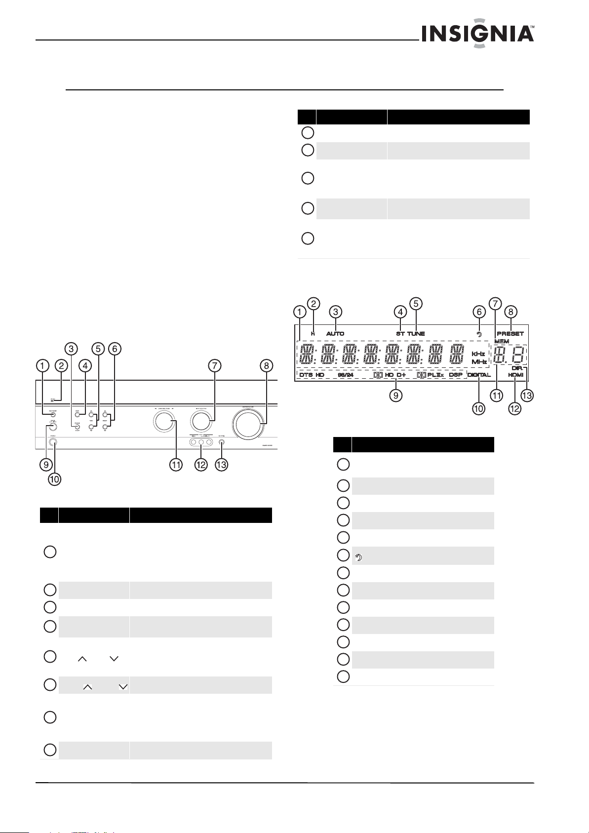
Front
# Item Description
9
POWER ON/OFF Press to turn your receiver on or off.
10
PHONES Plug headphones into this jack.
Rotate to select the sound mode. Each time you
11
SURROUND/STEREO
12
AUX1 VIDEO/L-AUDIO-R
13
SETUP MIC
rotate the knob slightly, you feel a click and, the
sound mode changes from auto to manual to
stereo.
Connect a standard (composite) video device to
these jacks.
Connect the setup microphone to this jack to use
the ROOM EQ feature. For more information, see
“Setting the listening environment (R OOM EQ)” on
page 16.
Display
# Item Description
When your receiver is turned on, press to put your
receiver in standby mode. Press again to put your
1
ON/STANDBY
2
STANDBY indicator Lights when your receiver is in standby mode.
3
SPEAKER ON/OFF Press to turn connected speakers on or off.
4
BAND
5
TUNE / TUNE
6
PRESET /PRESET
7
INPUT SELECTOR
8
MASTER VOLUME Rotate to adjust the overall volume.
receiver in operating mode.
When your receiver is in standby mode, electricity
still flows into it. To stop the flow of electricity,
press POWER.
Press to change the radio band from FM ST (stereo)
to FM MONO to AM.
Press to tune to the next or previous radio station.
Your receiver searches for the next or previous
station with a good signal and skips s tations with a
weak signals.
Press to go to the next or previous preset station.
Rotate to select the input source. Each time you
rotate the knob slightly, you feel a click and the
input source changes from TUNER to CD to TV to
GAME/AX2 to CBL/SAT (cable/satellite) to DVD to
AUX 1.
# Item
Status information, such as input, frequency,
1
volume level, and operating information
2
Headphones indicator
3
AUTO indicator
4
STEREO indicator
5
TUNE (tuned) indicator
6
(sleep indicator)
7
MEM (memory) indicator
8
PRESET indicator
9
Surround mode indicators
10
DIGITAL indicator
11
Preset number/sleep time display
12
HDMI indicator
13
DIR. (dire ct) indicator
www.insigniaproducts.com
3
NS-R5101HD 5.1 Surround Sound Receiver
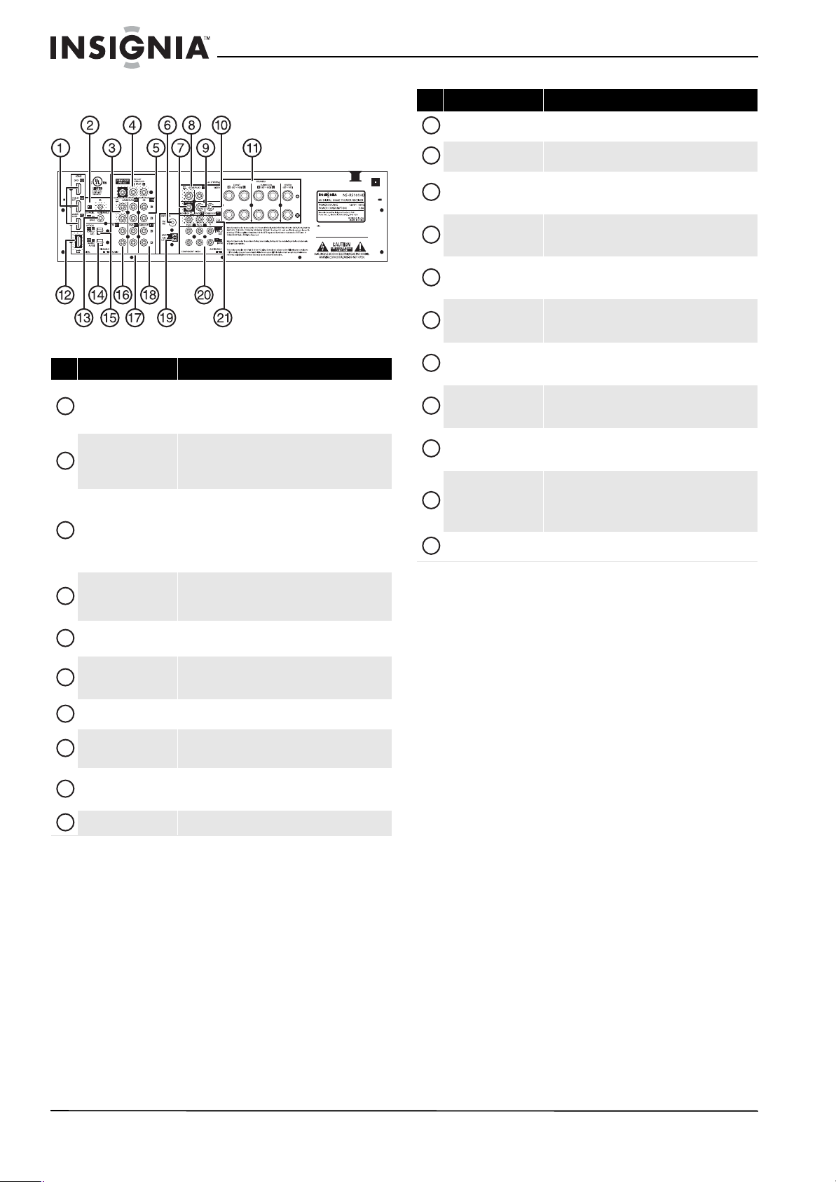
Back
# Item Description
HDMI IN DVD
1
HDMI IN CABLE/SAT
HDMI IN GAME/AUX2
2
IR IN
AUDIO OUT L/R
3
AUDIO IN GAME/AUX2
L/R
4
PRE OUTs
5
CD IN L/R AUDIO
6
ANTENNA FM 75Ω
7
MONITOR OUT
VIDEO OUT GAME AUX2
8
VIDEO IN GAME AUX2
9
VIDEO DVD IN
10
VIDEO CABLE/SAT IN Connect cable or satellite TV to this jack.
Connect HDMI devices to these jacks.
Connect an IR receiver to this jack. Using an IR receiver
is helpful when your receiver is in a cabinet or if you
want to control the receiver from an area outside the
range of the built-in remote control sensor.
Connect the audio for the device connected to the
VIDEO OUT GAME/AUX2 jack to the AUDIO OUT
GAME/AUX2 L/R jacks.
Connect the audio for the device connected to the
VIDEO IN GAME/AUX2 jack to the AUDIO IN
GAME/AUX2 L/R jacks.
Connect the SUBWOOFER PRE OUT jack to a powered
subwoofer and t he SURROUND BACK PRE OUT to the
power amplifier connected to speakers.
Connect a CD player to these jac ks. For more
information, see “Connecting a CD player” on page 10.
Connect an FM antenna to this jack. For more
information, see “Connecting an FM antenna” on
page 6.
Connect a TV to this jack. For more information, see
“Connecting a TV” on page 9.
Connect a VCR to these jacks. For more information,
see “Connecting a VCR” on page 8.
Connect a Blu-ray Disc player or DVD player to this jack.
For more information, see “Connecting a Blu-ray Disc
player or DVD player” on page 8.
# Item Description
11
SPEAKER
12
HDMI OUT
13
COAXIAL IN1
OPTICAL IN1
14
(GAME/AUX2 )
OPTICAL IN2
15
(CABLE/SAT)
16
TV IN AUDIO L/R
17
DVD IN AUDIO L/R
18
CABLE/SAT IN AUDIO L/R
19
ANTENNA GND/AM LOOP
COMPONENT VIDEO
IN1 (CABLE/SAT) and
20
COMPONENT VIDEO
IN2 (DVD)
21
COMPONENT VIDEO OUT
Connect speakers to these jacks. For more information,
see “Connecting speakers” on page 11.
Connect a TV to this jack. For more information, see
“Connecting a TV” on page 9.
Connect a coaxial digital audio device to this jack. For
more information, see “Connecting digital audio” on
page 10.
Connect an optical digital audio device to this jack. For
more information, see “Connecting digital audio” on
page 10.
Connect an optical digital audio device to this jack. For
more information, see “Connecting digital audio” on
page 10.
Connect the audio for a TV to hear its sound through
your receiver. For more inf ormation, see “Connec ting a
TV” on page 9.
Connect the audio for the device connected to the
COMPONENT VIDEO IN 1 (DVD) jacks or the VIDEO
DVD IN jack.
Connect the audio for the device connected to the
COMPONENT VIDEO IN 2 (CABLE/SAT) jacks or the
VIDEO DVD IN jack.
Connect an AM loop antenna to these jacks. For more
information, see “Connecting an AM antenna” on
page 7.
Connect component video devices to these jacks. For
more information, see “Connecting a Blu-ray Disc
player or DVD player” on page 8.
Connect a TV to these jacks. For more information, see
“Connecting a TV” on page 9.
4
www.insigniaproducts.com

5.1 Surround Sound Receiver
Remote control
# Item Description
11
LED indicator Lights when you press a button.
12
STANDBY Press to put your receiver in standby mode.
13
D.INPUTS
14
DIMMER
15
DISPLAY
16
ENTER/MEMO Press to confirm selections.
17
PRESET / P RESET
18
RETURN In menu mode, press to return to a previous menu.
19
MUTE
20
VOL+ /VOL– Press to increase or decrease the master volume.
21
CH LEVEL
22
CH LEVEL + / CH LEVEL –
23
TREBLE+ / TREBLE– Press to increase or decrease the treble.
Press to select the audio input. For more information,
see “Selecting the input s ource” on page 17.
Press to adjust the brightness of the display. You can
select ON, dim, dimmer, or OFF.
Press to change the status information on the display.
You can view information for the surround mode,
volume, or input source.
Press to select a preset radio station.
In menu mode, press to adjust an option.
Press to mute the sound. Press again to restore the
sound.
Press to select a channel level you want to adjust, then
press CH LEVEL + or CH LEVEL – to adjust the
channel. For more information, see “Adjusting a
channel level” on page 21.
Press to increase or decrease the output from a
selected channel. For more information, see
“Adjusting a channel level” on page 21.
# Item Description
1
POWER ON
2
Input selector
3
Numbers
4
SLEEP
5
SETUP
6
TUNE / TUNE
7
SOUND PARAMETER
SURROUND /
8
SURROUND
9
STEREO Press to select stereo (2-channel downmix) mode.
10
BASS+ / BASS– Press to increase or decrease the bass.
When in standby mode, press to enter operating
mode.
Press these buttons to select an input source. For more
information, see “Selecting the input source” on
page 17.
Press to select a preset station.
Press to set the sleep time. The sleep timer will
automatically turn off your receiver after a preset time.
You can select 30 minutes, 60 minutes, 90 minutes,
or OFF.
Press to open the on-screen display (OSD). For more
information, see “Using the on-screen display (OSD)”
on page 20.
Press to select a the radio station. Press and hold for
more than 0.5 seconds to search for the next or
previous station with a good signal.
Press to select a sound parameter you want to adjust.
For more information, see “Adjusting sound
parameters” on page 19.
Press to select a surround mode.
In menu mode, press to select an option.
Using the remote control
Installing remote control batteries
To install remote control batteries:
1 Remove the battery compartment cover.
2 Insert two AAA batteries into the battery
compartment. Make sure that the + and –
symbols on the batteries match the + and –
symbols inside the battery compartment.
3 Replace the cover.
Notes
• Remove the batteries when you do not plan to
use the remote control for a long period of time.
• Do not use the rechargeable batteries
(Ni-Cd type).
www.insigniaproducts.com
5
 Loading...