

Insignia NS-PDP50, NS-PDP42 User Manual
APPENDIX
89
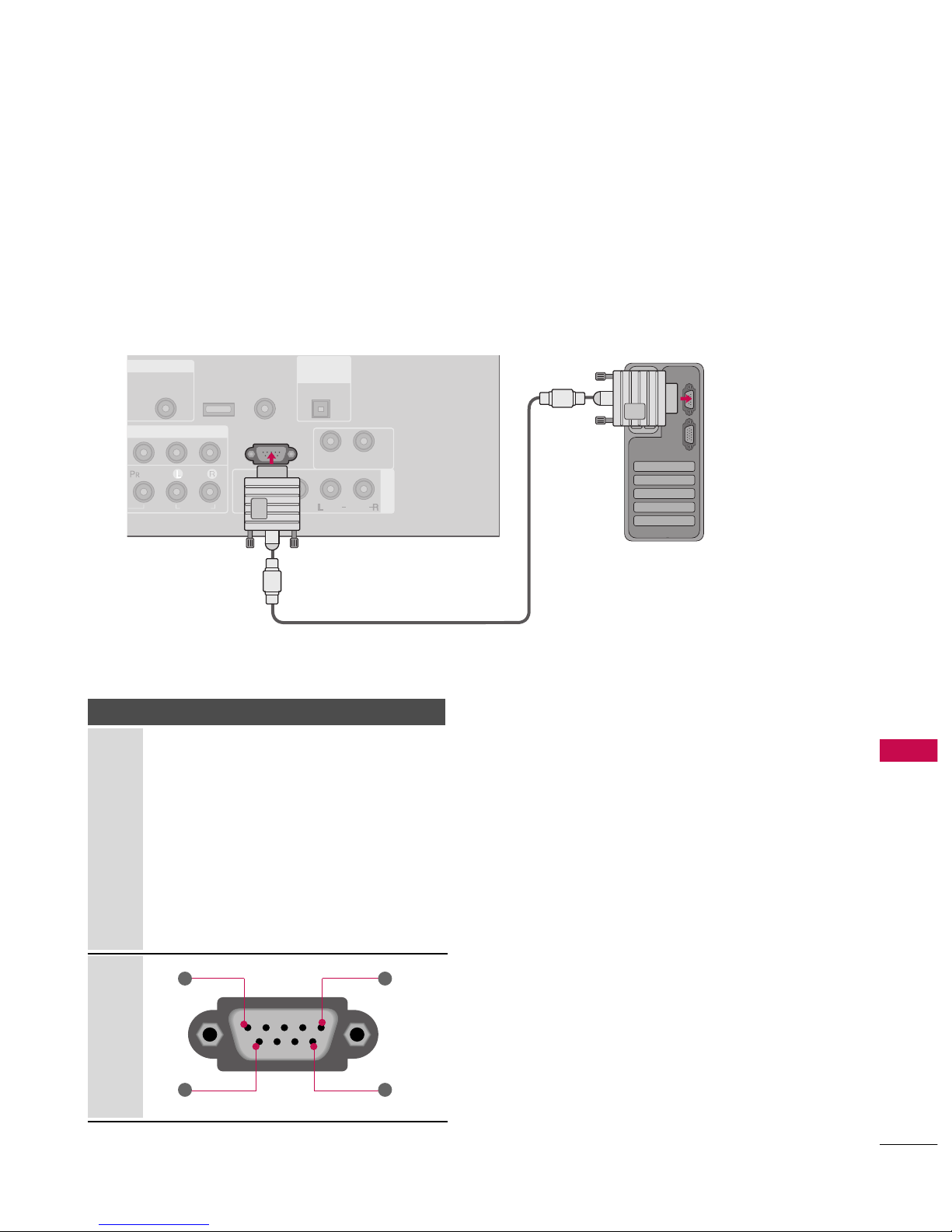
EXTERNAL CONTROL THROUGH RS-232C
RS-232C Setup
The RS-232C port allows you connect the RS-232C input jack to an external control device (such as a computer
or an A/V control system) to control the TV’s functions externally.
■
Note: RS-232C on this unit is intended to be used with third party RS-232 control hardware and software.
The instructions below are provided to help with programming software or to test functionality using telenet
software.
AV IN 1
AUDIO
(RGB/DVI)
RS-232C IN
(CONTROL & SERVICE)
AUDIO
AUDIO OUT
VIDEO
MONO
( )
AUDIO
S-VIDEO
REMOTE
CONTROL IN
SERVICE
DIGITAL
AUDIO OUT
OPTICAL
Type of Connector; D-Sub 9-Pin Male
No. Pin Name
1 No connection
2 RXD (Receive data
)
3 TXD (Transmit data
)
4 DTR (DTE side ready
)
5 GND
6 DSR (DCE side ready
)
7 RTS (Ready to send
)
8 CTS (Clear to send
)
9 No Connection
1
6
5
9
PC
APPENDIX
90
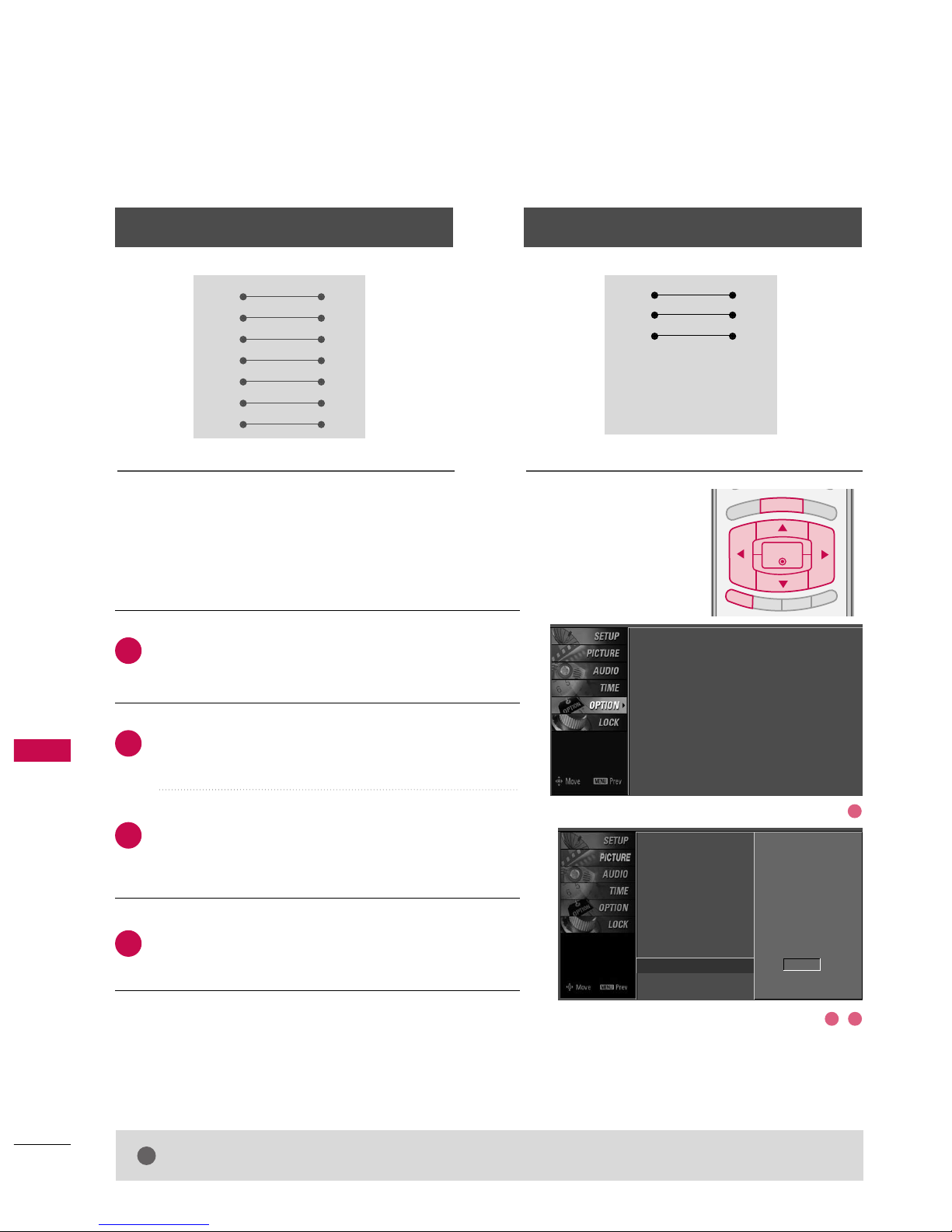
RS-232C Configurations
APPENDIX
Press the
MMEENNUU
button and then useDDor EEbutton
to select the
OOPPTTIIOONN
menu.
Press the
GG
button and then useDDor EEbutton to
select
SSeett IIDD
.
Press the
GG
button and then useDDor EEbutton to
adjust
SSeett IIDD
to choose the desired TV ID number.
The adjustment range of Set ID is 1~ 99.
Press
EEXXIITT
button to return to TV viewing or press
MMEENNUU
button to return to the previous menu.
Use this function to specify a TV ID number.
Refer to ‘Real Data Mapping1’.
GG
pp..9933
.
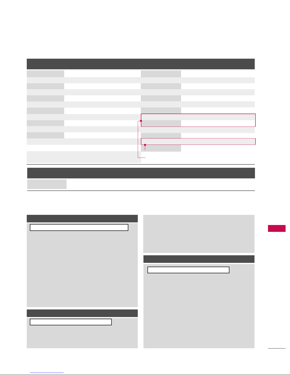
Either cable below can be used.
Set ID
B
R
IG
H
T
-
BRIGHT +
ENTER
T
IM
E
R
R
A
T
IO
SIMPLINK
E
X
IT
MENU
Communication Parameters
■
Baud rate: 9600 bps (UART
)
■
Data length: 8 bits
■
Parity: None
■
Stop bit: 1 bit
■
Communication code: ASCII code
■
Use a crossed (reverse) cable.
2
1
3
4
PC TV
RXD 2 3 TXD
TXD 3 2 RXD
GND 5 5 GND
DTR 4 6 DSR
DSR 6 4 DTR
RTS 7 8 CTS
CTS 8 7 RTS
D-Sub 9 D-Sub 9
PC TV
RXD 2 3 TXD
TXD 3 2 RXD
GND 5 5 GND
DTR 4 6 DTR
DSR 6 4 DSR
RTS 7 7 RTS
CTS 8 8 CTS
D-Sub 9 D-Sub 9
7-Wire Configuration
(
Serial female-female NULL modem cable
)
3-Wire Configurations
(
Not standard
)
NOTE
!
GG
This product has command echo back in the RS-232C Command.
Language : English
Input Label
SimpLink : Off
Key Lock : Off
Caption : Off
ISM Method : Orbiter
Low Power : Off
Set ID : 1
Language
Input label
SimpLink
Key Lock
Caption
ISM Method
Low Power
Set ID
G
1
1
32
APPENDIX
91
Command Reference List
CC OOMM MMAA NN DD11 CC OOMM MMAA NN DD22
24. Channel Tuning
DATA
(Hexadecimal)
CC OOMM MMAA NN DD11 CC OOMM MMAA NN DD22
DATA
(Hexadecimal)
CC OOMMMM AANNDD11 CCOOMMMMAANN DD22
DATA 0
(Hexadecimal)
DATA 1
(Hexadecimal)
DATA 2
(Hexadecimal)
DATA 3
(Hexadecimal)
DATA 4
(Hexadecimal)
DATA 5
(Hexadecimal)
physical major major low minor high minor low attribute
program high program low
ma
01. Power k a 0 ~ 1
02. Input Select k b (
GG
p.92)
03. Input Select x b (
GG
p.92)
04. Aspect Ratio k c (
GG
p.92)
05. Screen Mute k d 0 ~ 1
06. Volume Mute k e 0 ~ 1
07. Volume Control k f 0 ~ 64
08. Contrast k g 0 ~ 64
09. Brightness k h 0 ~ 64
10. Color k i 0 ~ 64
11. Tint k j 0 ~ 64
12. Sharpness k k 0 ~ 64
13. OSD Select k l 0 ~ 1
14. Remote Control
Lock Mode
Transmission / Receiving Protocol
TT rraannss mmiissss iioonn
[Command 1]: First command to control the set.
(j, k, m or x)
[Command 2]: Second command to control the set.
[Set ID] : You can adjust the set ID to choose desired TV ID
number in Setup menu. Adjustment range is 1
~ 99.
When selecting Set ID ‘0’, every connected the TV is
controlled. Set ID is indicated as decimal (1
~ 99
)
on
menu and as Hexa decimal (0x0
~ 0x63
)
on transmission
/receiving protocol.
[DATA]: To transmit the command data.
Transmit the ‘FF’ data to read status of command.
[Cr]: Carriage Return
ASCII code ‘0x0D’
[ ]: ASCII code ‘space (0x20)’
* In this model, TV will not send the status during the standby mode.
OOKK AAcckknnooww lleeddgg eemmeenntt
The TV transmits ACK (acknowledgement) based on this format when receiving normal data. At this time, if the data is
data read mode, it indicates present status data. If the data is
data write mode, it returns the data of the PC computer.
* In this model, TV will not send the status during the standby mode.
* Data Format
[Command 2]: Use as command.
[Set ID]: Use the small character, if set ID is 10, it will send the ‘0’, ‘a’.
[DATA]: Use the small character, if data is 0 x ab, it will send the ‘a’, ‘b’.
[OK]: Use the large character.
EErrrroorr AAcckknnoowwlleeddgg eemm eenn tt
The TV transmits ACK (acknowledgement) based on this format when receiving abnormal data from non-viable functions
or communication errors.
Data1: Illegal Code
Data2: Not supported function
Data3: Wait more time
* In this model, TV will not send the status during the standby mode.
* Data Format
[Command 2]: Use as command.
[Set ID]: Use the small character, if set ID is 10, it will send the ‘0’, ‘a’.
[DATA]: Use the small character, if data is 0 x ab, it will send the ‘a’, ‘b’.
[NG]: Use the large character
[[ CC oo mmmmaann dd 11]][[CC oo mmmmaa nndd22]] [[ ]][[SSeett IIDD]] [[ ]][[ DDaattaa]][[CC rr]]
[[ CC oo mmmmaann dd 22]] [[ ]][[SSeett IIDD]] [[ ]][[ OO KK]] [[DDaattaa]][[xx ]]
[[ CC oo mmmmaann dd 22]] [[ ]][[SSeett IIDD]] [[ ]][[NNGG]][[DDaa ttaa ]][[xx]]
15. Treble k r 0 ~ 64
16. Bass k s 0 ~ 64
17. Balance k t 0 ~ 64
18 .
Color Temperature
k u 0 ~ 3
19. Red Adjustment k v 0 ~ C8
20. Green Adjustment k w 0 ~ C8
21. Blue Adjustment k $ 0 ~ C8
22. ISM Method j p (
GG
p.94)
23 . Lo w P ow er j q 0 ~ 1
25. Channel Add/Del m b 0 ~ 1
26. Key m c (
GG
p.95)
27. Back Light m g 0 ~ 64
0 ~ 1
k m
Plasma TV Model Only
LCD TV Model Only
 Loading...