

Insignia NS-OTR16SS8Q Installation Manual
INSTALLATION GUIDE
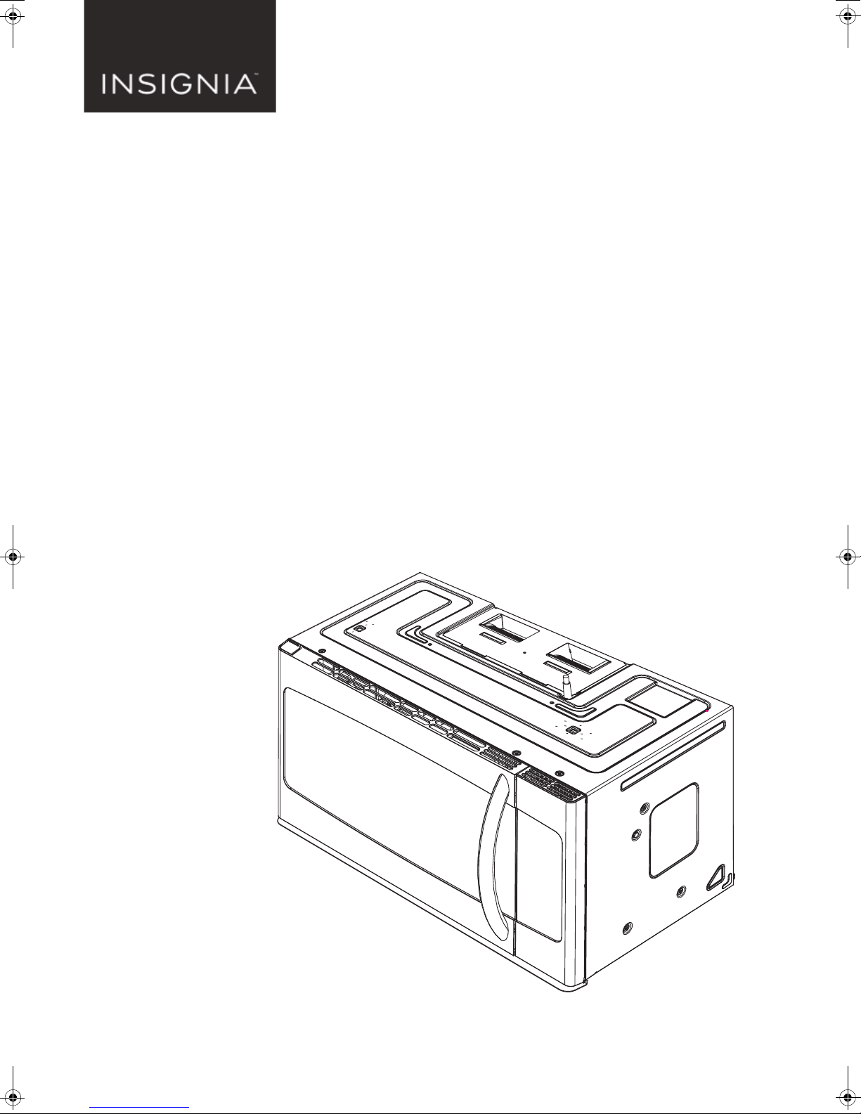
1.6 Cu. Ft.
Over-the-Range
Microwave
NS-OTR16SS8Q
Before using your new product, please read these instructions to prevent any damage.

Contents
Introduction . . . . . . . . . . . . . . . . . . . . . . . . . . . . . . . . . . . . . . . . . . . . . . . . . . . . . . . . . . . . . . . . . . . . . . . . . . . . . 3
BEFORE YOU BEGIN . . . . . . . . . . . . . . . . . . . . . . . . . . . . . . . . . . . . . . . . . . . . . . . . . . . . . . . . . . . . . . . . . . . . . . 3
IMPORTANT SAFETY INSTRUCTIONS . . . . . . . . . . . . . . . . . . . . . . . . . . . . . . . . . . . . . . . . . . . . . . . . . . . . . . 3
Package contents . . . . . . . . . . . . . . . . . . . . . . . . . . . . . . . . . . . . . . . . . . . . . . . . . . . . . . . . . . . . . . . . . . . . . . . . 4
Before you install . . . . . . . . . . . . . . . . . . . . . . . . . . . . . . . . . . . . . . . . . . . . . . . . . . . . . . . . . . . . . . . . . . . . . . . . 5
Removing your microwave . . . . . . . . . . . . . . . . . . . . . . . . . . . . . . . . . . . . . . . . . . . . . . . . . . . . . . . . . . . . . . . 9
Installing your microwave . . . . . . . . . . . . . . . . . . . . . . . . . . . . . . . . . . . . . . . . . . . . . . . . . . . . . . . . . . . . . . . 10
Before using your microwave . . . . . . . . . . . . . . . . . . . . . . . . . . . . . . . . . . . . . . . . . . . . . . . . . . . . . . . . . . . 40
Template dimensions . . . . . . . . . . . . . . . . . . . . . . . . . . . . . . . . . . . . . . . . . . . . . . . . . . . . . . . . . . . . . . . . . . . 41
Obtaining replacement parts . . . . . . . . . . . . . . . . . . . . . . . . . . . . . . . . . . . . . . . . . . . . . . . . . . . . . . . . . . . . 43
Specifications . . . . . . . . . . . . . . . . . . . . . . . . . . . . . . . . . . . . . . . . . . . . . . . . . . . . . . . . . . . . . . . . . . . . . . . . . . 43
Legal notices . . . . . . . . . . . . . . . . . . . . . . . . . . . . . . . . . . . . . . . . . . . . . . . . . . . . . . . . . . . . . . . . . . . . . . . . . . . 43
ONE-YEAR LIMITED WARRANTY . . . . . . . . . . . . . . . . . . . . . . . . . . . . . . . . . . . . . . . . . . . . . . . . . . . . . . . . . 43
ELECTRICAL REQUIREMENTS . . . . . . . . . . . . . . . . . . . . . . . . . . . . . . . . . . . . . . . . . . . . . . . . . . . . . . . . . . . . . . . . . . . . . . . . . . .3
Parts . . . . . . . . . . . . . . . . . . . . . . . . . . . . . . . . . . . . . . . . . . . . . . . . . . . . . . . . . . . . . . . . . . . . . . . . . . . . . . . . . . . . . . . . . . . . . . . . . .4
Hardware . . . . . . . . . . . . . . . . . . . . . . . . . . . . . . . . . . . . . . . . . . . . . . . . . . . . . . . . . . . . . . . . . . . . . . . . . . . . . . . . . . . . . . . . . . . . . 4
Tools and materials needed . . . . . . . . . . . . . . . . . . . . . . . . . . . . . . . . . . . . . . . . . . . . . . . . . . . . . . . . . . . . . . . . . . . . . . . . . . . . 5
Mounting requirements . . . . . . . . . . . . . . . . . . . . . . . . . . . . . . . . . . . . . . . . . . . . . . . . . . . . . . . . . . . . . . . . . . . . . . . . . . . . . . .6
Exhaust requirements . . . . . . . . . . . . . . . . . . . . . . . . . . . . . . . . . . . . . . . . . . . . . . . . . . . . . . . . . . . . . . . . . . . . . . . . . . . . . . . . .7
Step 1: Find the wall studs . . . . . . . . . . . . . . . . . . . . . . . . . . . . . . . . . . . . . . . . . . . . . . . . . . . . . . . . . . . . . . . . . . . . . . . . . . . .10
Step 2: Align the rear wall template . . . . . . . . . . . . . . . . . . . . . . . . . . . . . . . . . . . . . . . . . . . . . . . . . . . . . . . . . . . . . . . . . . .11
Step 3: Select a ventilation type . . . . . . . . . . . . . . . . . . . . . . . . . . . . . . . . . . . . . . . . . . . . . . . . . . . . . . . . . . . . . . . . . . . . . . .13
Step 4: Option A - Attach the mounting plate to the wall . . . . . . . . . . . . . . . . . . . . . . . . . . . . . . . . . . . . . . . . . . . . . . .14
Step 5: Option A - Preparing the top cabinet . . . . . . . . . . . . . . . . . . . . . . . . . . . . . . . . . . . . . . . . . . . . . . . . . . . . . . . . . . .16
Step 6: Option A - Insert the exhaust adapter . . . . . . . . . . . . . . . . . . . . . . . . . . . . . . . . . . . . . . . . . . . . . . . . . . . . . . . . . .18
Step 8: Option A - Mount the microwave . . . . . . . . . . . . . . . . . . . . . . . . . . . . . . . . . . . . . . . . . . . . . . . . . . . . . . . . . . . . . .19
Step 9: Option A - Connecting ductwork . . . . . . . . . . . . . . . . . . . . . . . . . . . . . . . . . . . . . . . . . . . . . . . . . . . . . . . . . . . . . .21
Step 4: Option B - Cutting a vent opening . . . . . . . . . . . . . . . . . . . . . . . . . . . . . . . . . . . . . . . . . . . . . . . . . . . . . . . . . . . . .22
Step 5: Option B - Attach the mounting plate to the wall . . . . . . . . . . . . . . . . . . . . . . . . . . . . . . . . . . . . . . . . . . . . . . .23
Step 6: Option B - Preparing the top cabinet . . . . . . . . . . . . . . . . . . . . . . . . . . . . . . . . . . . . . . . . . . . . . . . . . . . . . . . . . . .25
Step 7: Option B - Adapt the microwave blower for outside back exhaust . . . . . . . . . . . . . . . . . . . . . . . . . . . . . . .27
Step 8: Option B - Mount the microwave . . . . . . . . . . . . . . . . . . . . . . . . . . . . . . . . . . . . . . . . . . . . . . . . . . . . . . . . . . . . . .30
Step 4: Option C - Attach the mounting plate to the wall . . . . . . . . . . . . . . . . . . . . . . . . . . . . . . . . . . . . . . . . . . . . . . .32
Step 5: Option C - Preparing the top cabinet . . . . . . . . . . . . . . . . . . . . . . . . . . . . . . . . . . . . . . . . . . . . . . . . . . . . . . . . . . .34
Step 6: Option C - Adapting blower for recirculation . . . . . . . . . . . . . . . . . . . . . . . . . . . . . . . . . . . . . . . . . . . . . . . . . . .36
Step 7: Option C - Mount the microwave . . . . . . . . . . . . . . . . . . . . . . . . . . . . . . . . . . . . . . . . . . . . . . . . . . . . . . . . . . . . . .38
Rear wall template dimensions . . . . . . . . . . . . . . . . . . . . . . . . . . . . . . . . . . . . . . . . . . . . . . . . . . . . . . . . . . . . . . . . . . . . . . .41
Top cabinet template dimensions . . . . . . . . . . . . . . . . . . . . . . . . . . . . . . . . . . . . . . . . . . . . . . . . . . . . . . . . . . . . . . . . . . . . .42
2
www.insigniaproducts.com
Introduction
Ensure proper
ground before
use
Congratulations on your purchase of a high-quality Insignia product. Your NS-OTR16SS8Q represents the state of
the art in microwave design and is designed for reliable and trouble-free performance.
This installation guide will show you how to install your new over-the-range microwave.
BEFORE YOU BEGIN
Read these instructions completely and carefully.
• IMPORTANT – Save these instructions for local inspector’s use.
• IMPORTANT – Observe all governing codes and ordinances.
• Note to Installer – Be sure to leave these instructions with the consumer.
• Note to Consumer – Keep these instructions for future reference.
• Skill level – Installation of this appliance requires basic mechanical and electrical skills.
• Proper installation is the responsibility of the installer.
• Product failure due to improper installation is not covered under the Warranty.
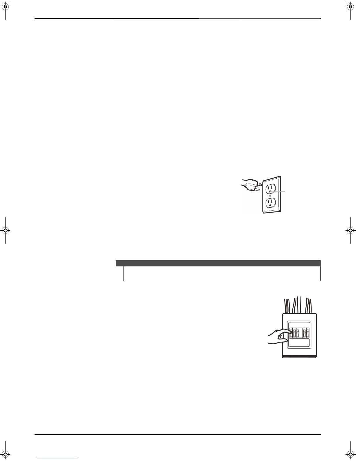
IMPORTANT SAFETY INSTRUCTIONS
IMPORTANT–PLEASE READ CAREFULLY. FOR PERSONAL SAFETY, THIS APPLIANCE MUST BE PROPERLY GROUNDED
TO AVOID SEVERE OR FATAL SHOCK.
This product requires a three-prong, properly grounded outlet for safe
operation. If not properly grounded, or if the outlet box does not meet
electrical requirements noted (under ELECTRICAL REQUIREMENTS), a qualified
electrician should be employed to correct any deficiencies.
The power cord of this appliance is equipped with a three-prong (grounding)
plug which mates with a standard three-prong (grounding) wall receptacle to
minimize the possibility of electric shock hazard from this appliance.
You should have the wall receptacle and circuit checked by a qualified electrician to make sure that the receptacle is
properly grounded.
Where a standard two-prong wall receptacle is encountered, it is very important to have it replaced with a properly
grounded three-prong wall receptacle installed by a qualified electrician.
DO NOT, UNDER ANY CIRCUMSTANCES, CUT, DEFORM, OR REMOVE ANY OF THE PRONGS FROM THE POWER CORD.
DO NOT USE WITH AN EXTENSION CORD.
1.6 Cu. Ft. Over-the-Range Microwave
Note
Caution
For personal safety, remove the house fuse or open the circuit breaker before beginning
installation to avoid severe or fatal shock injury.
For personal safety, the mounting surface must be capable of supporting the cabinet load,
in addition to the added weight of this 54 pound (24 kilogram) product, plus additional
oven loads of up to 50 pounds (22 kilograms) for a total weight of 104 pounds (47
kilograms).
For personal safety, this product cannot be installed in cabinet arrangements such as an
island or a peninsula. It must be mounted to BOTH a top cabinet AND a wall.
ELECTRICAL REQUIREMENTS
The product rating of your microwave is 120 volts AC, 60 Hertz, 15 amps, and 1.6 kilowatts. This product must be
connected to a supply circuit of the proper voltage and frequency. Wire size must conform to the requirements of
the National Electrical Code or the prevailing local code for this kilowatt rating. The power supply cord and plug
should be brought to a separate 20 ampere branch circuit single grounded outlet. The outlet box should be located
in the cabinet above the microwave oven. The outlet box and supply circuit should be installed by a qualified
electrician and conform to the National Electrical Code or the prevailing local code.
For easier installation and personal safety, it is recommended that two people
install this product.
www.insigniaproducts.com
3
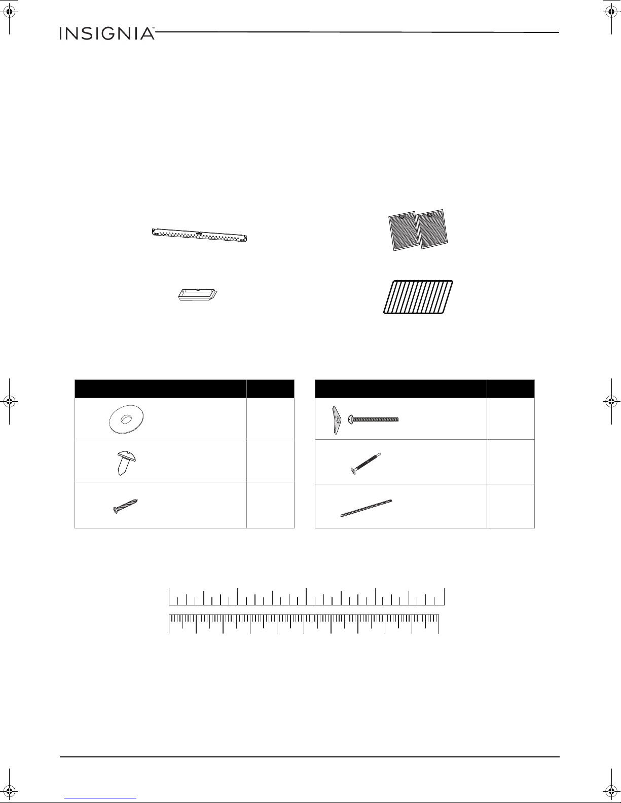
Package contents
Mounting plate (Qty. 1)
(ships attached to microwave)
Exhaust adapter (Qty. 1)
Grease filters (Qty. 2)
Oven rack (Qty. 1)
Hardware Qty.
2
2
2
Washers
Sheet metal
screws
Wood screws
(1/4” × 2”)
Hardware Qty.
2
2
1
Toogle bolts with
wing nuts
(3/16” × 3”)
Self-aligning
machine screws
(20-1/4” × 3”)
Nylon grommet
10 20 30 40 50 60 70 80 90 1 00mm
1234in
• 1.6 cu. ft. over-the-range microwave
• Turntable (with ring)
• Installation parts (see “Parts” on page 4)
• Installation hardware (see “Hardware” on page 4)
• Mounting templates (2)
• Installation Guide
•User Guide
Parts
Make sure that you have all the parts necessary to install your new microwave.
NS-OTR16SS8Q
Hardware
4
www.insigniaproducts.com
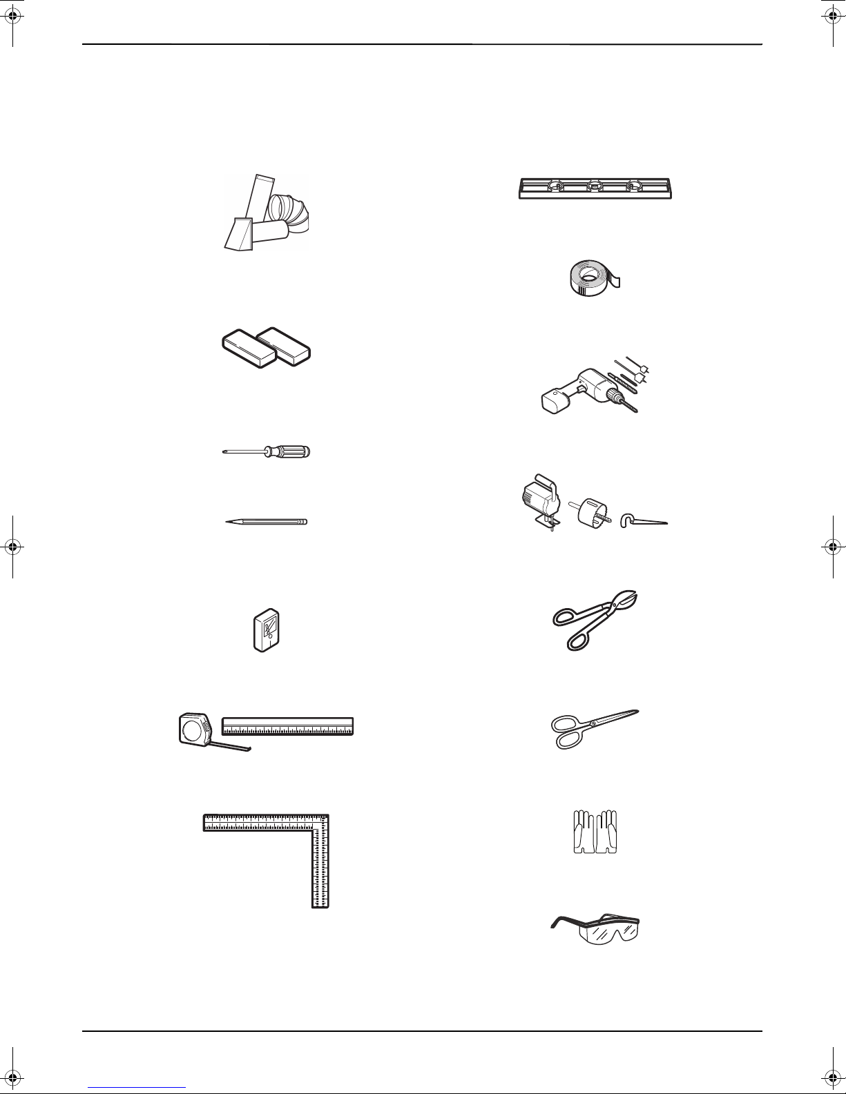
Before you install
#1 and #2 Phillips screwdrivers
Pencil
Tin snips
(to cut damper, if needed)
Scissors
(to cut template, if needed)
Gloves
Safety goggles
Saw
(saber, hole, or keyhole)
Ruler or tape measure
Electric drill with 3/16”, 1/2”, and 5/8” bits
Edge-to-edge stud finder
Level
Duct tape
Filler blocks or scrap wood pieces
(for top cabinet spacing in recessed bottom
cabinet installations, if needed)
Carpenter square
(optional)
Ducts (if venting outside)
See “Exhaust requirements” on page 7
Read these instructions completely before installing your microwave. Make sure that your space meets the
mounting requirements and that you’ve gathered all needed tools and materials.
Tools and materials needed
1.6 Cu. Ft. Over-the-Range Microwave
www.insigniaproducts.com
5
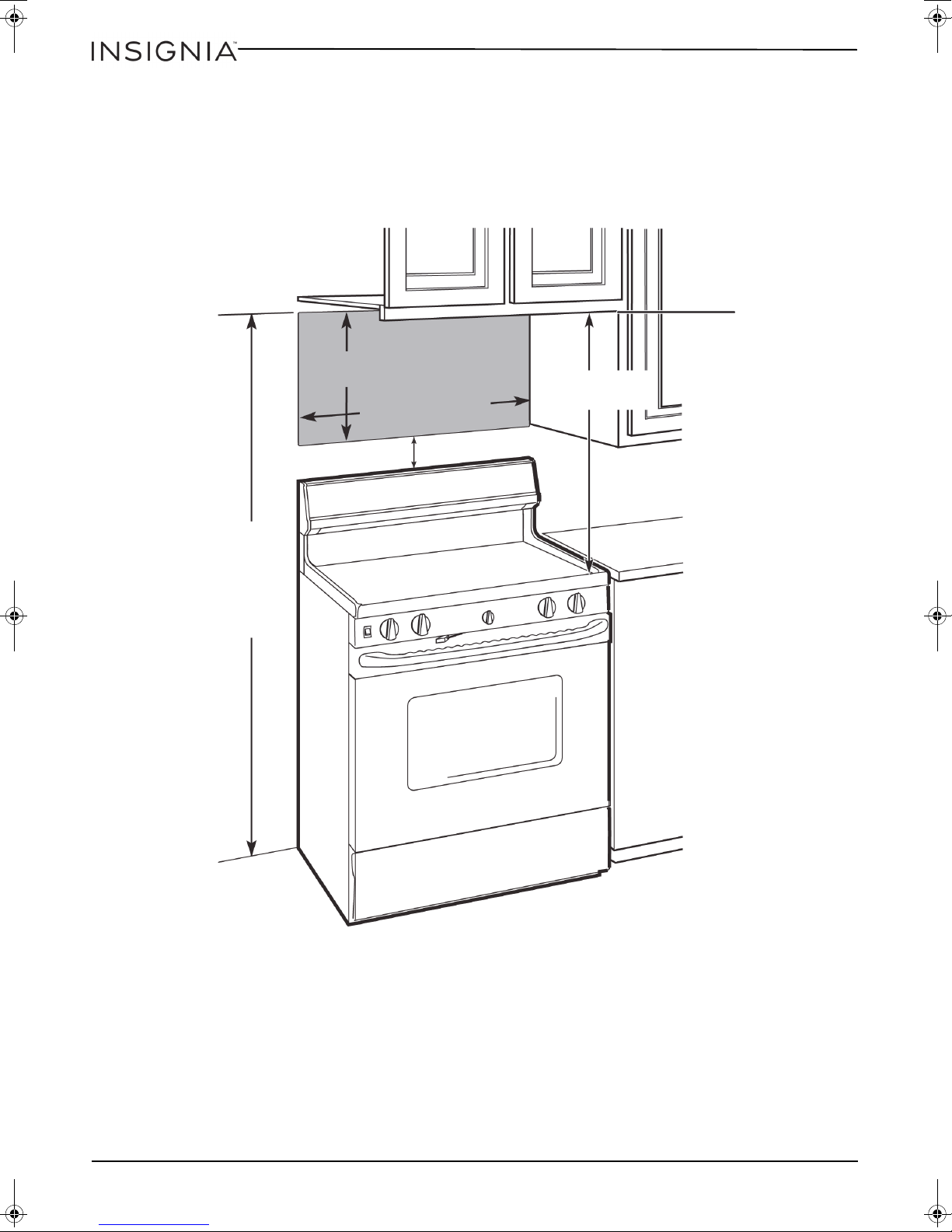
Mounting requirements
66 in. (167.6 cm) or more
from the floor to the top of
the microwave
16-1/2 in.
(41.9 cm)
3
0
i
n
.
(
7
6
.
2
c
m
)
30 in.
(76.2 cm)
2 in. (5.1 cm)
• The space between the cabinets must be 30 in. (76.2 cm) wide. If the space between the cabinets is more than 30
in. (76.2 cm), you’ll need filler material to fill the gap between the microwave and cabinets.
• This microwave is for installation over ranges up to 36 in. (91.4 cm) wide.
• If installing the microwave beneath smooth, flat cabinets, make sure that you leave enough space for the power
cord clearance.
• If you are going to vent your exhaust to the outside, see “Exhaust requirements” on page 7 for exhaust duct
preparation.
NS-OTR16SS8Q
6
www.insigniaproducts.com
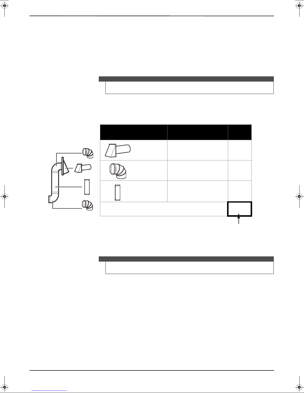
Exhaust requirements
EX
AM
P
LE
Duct Pieces
Equivalent
Length
×
Number
Used
=
Tot a l
Equivalent
Length
40 ft. ×
(
1 )
=
40 ft.
10 ft. ×
(
2 )
=
20 ft.
3 ft. ×
(
1 )
=
3 ft.
Tot al duc twork =
63 ft.
Roof cap
90° elbow
Straight duct 6” round
OR
3-1/4” × 10” rectangular
For proper airflow, this
number should not
exceed 140 ft.
Use the “Equivalent duct length table” on page 8 to calculate the equivalent ductwork length for your setup.
Example setup:
Use this section if you plan to vent your microwave outside (top or back exhaust). If you plan to recirculate the air
back into the room, skip to “Removing your microwave” on page 9.
When installing exhaust vents:
• Use the most direct route with as few elbows/transitions as possible. This helps prevent blockages and ensures
that the exhaust is being vented correctly.
• Your microwave is designed to mate with a standard 3-1/4” × 10” rectangular duct. If a round duct is required, a
retangular-to-round transition adapter must be used. Do not use a duct with a diameter less than 6”.
• Elbows, transitions, and wall/roof caps add resistance to airflow. Each of these pieces are equivalent to a section
of straight duct that is longer than their actual physical size. When calculating your duct length, add the
equivalent lengths of all the pieces together. For proper airflow, the equivalent airflow should not exceed 140 ft.
For example:
1.6 Cu. Ft. Over-the-Range Microwave
Note
If a rectangular-to-round transition adapter is used, you must cut the bottom
corners of the damper wih tin snips to let the damper have free movement.
Note
Equivalent lengths of duct pieces are based on actual tests and reflect
requirements for good venting performance with any vent hood.
www.insigniaproducts.com
7
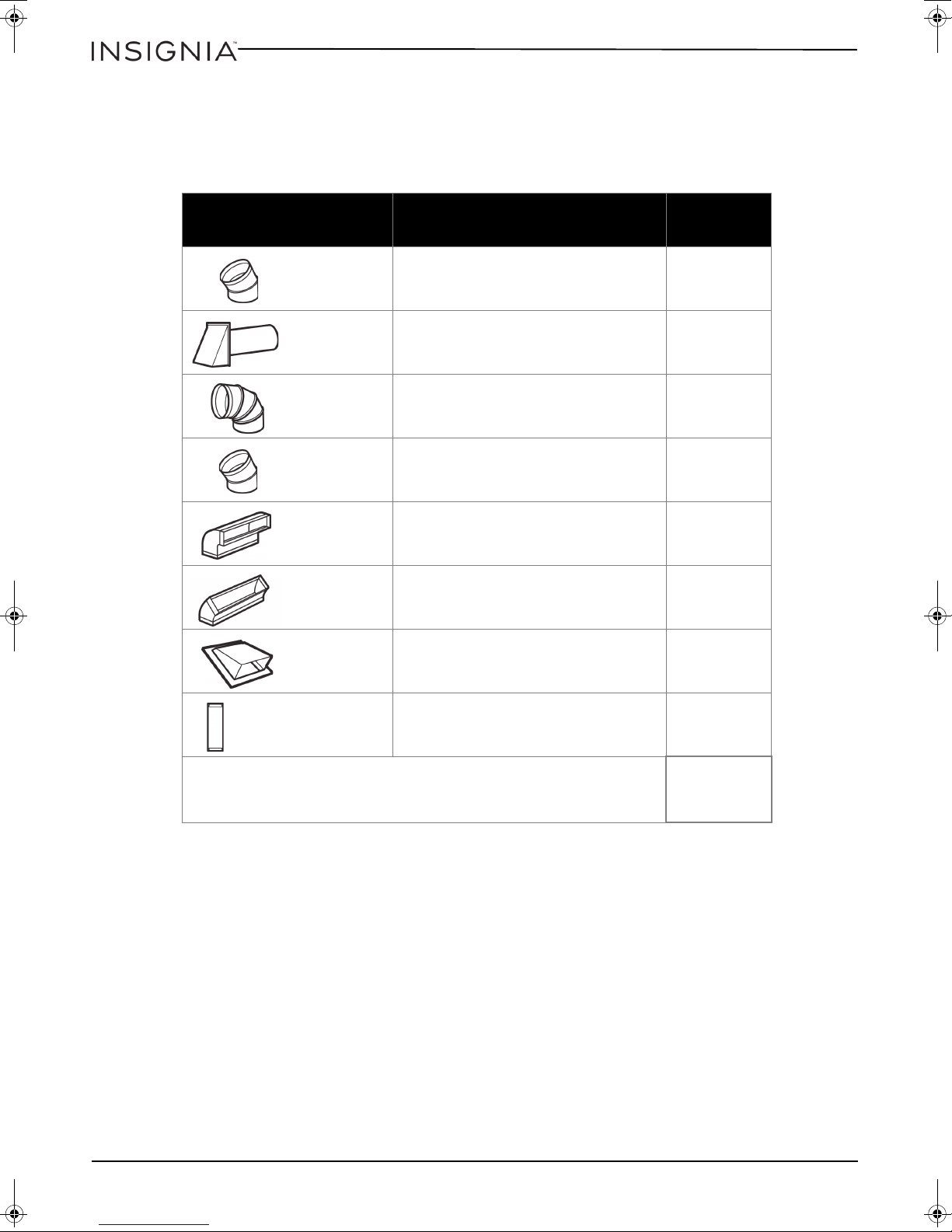
Equivalent duct length table
Rectangular-toround transition
adapter
Wall cap
90° elbow
45° elbow
90° elbow
45° elbow
Roof cap
Straight duct 6” round
OR
3-1/4” × 10” rectangular
To calculate your equivalent duct length:
1 Write the number of sections used for each of the duct pieces.
2 Multiply the number used by the equivalent length for each duct piece.
3 Add the total equivalent lengths together. This number must be less than 140 ft.
NS-OTR16SS8Q
Duct Pieces
Equivalent
Length
5 ft. × ( ) = ft.
40 ft. × ( ) = ft.
10 ft. × ( ) = ft.
5 ft. × ( ) = ft.
25 ft. × ( ) = ft.
5 ft. × ( ) = ft.
× Number Used =
To ta l
Equivalent
Length
24 ft. × ( ) = ft.
1 ft. × ( ) = ft.
Total ductwork =
(For proper airflow, this
number should not
exceed 140 ft.)
ft.
8
www.insigniaproducts.com
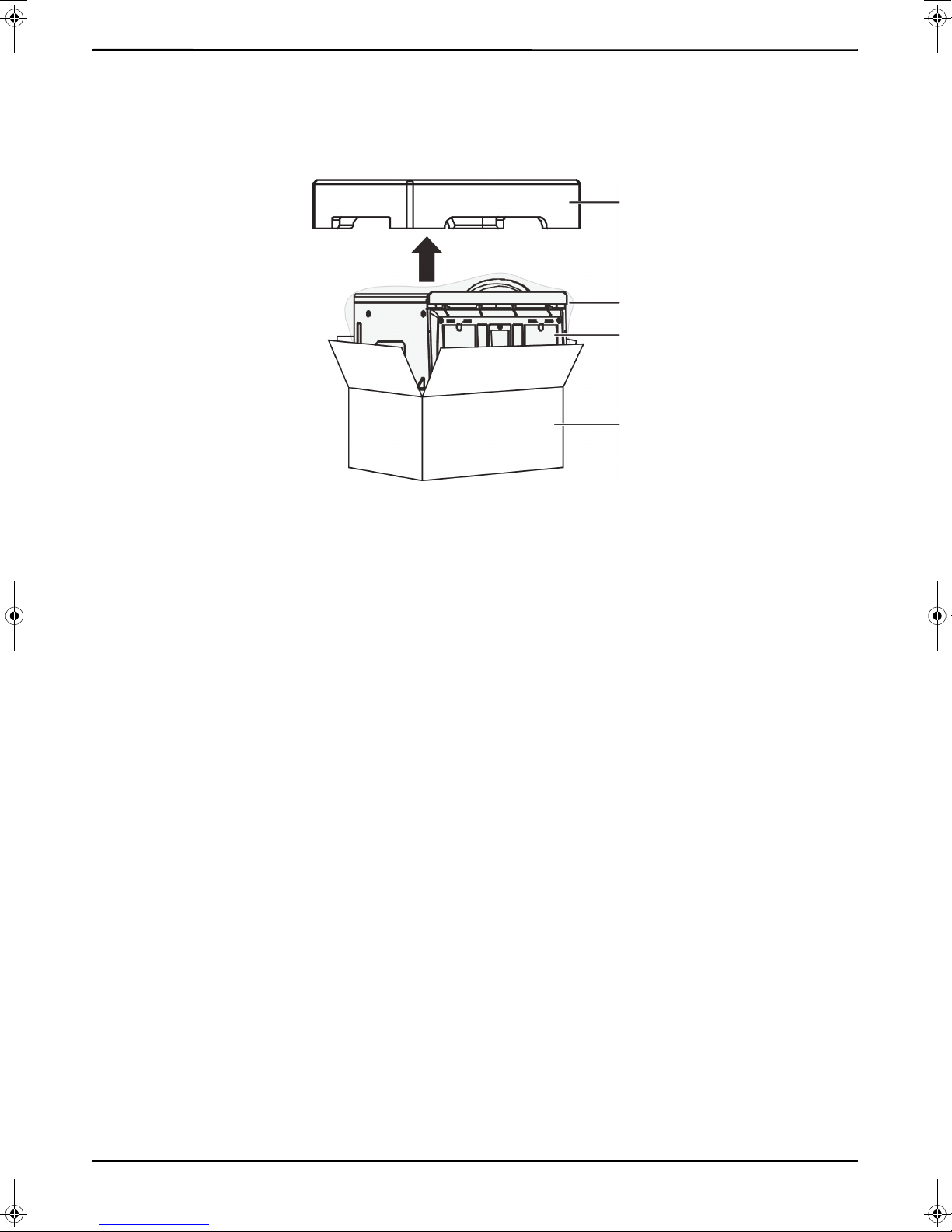
Removing your microwave
Styrofoam
Box
Microwave
Pastic bag
1 Remove the upper styrofoam from the box. Keep all the accessories.
2 Pull the microwave out of the box.
3 Remove and throw away the plastic bags.
1.6 Cu. Ft. Over-the-Range Microwave
www.insigniaproducts.com
9
Installing your microwave
Wall
stud
Center of the
wall stud
Pencil
Ruler or tape measure
Edge-to-edge stud finder
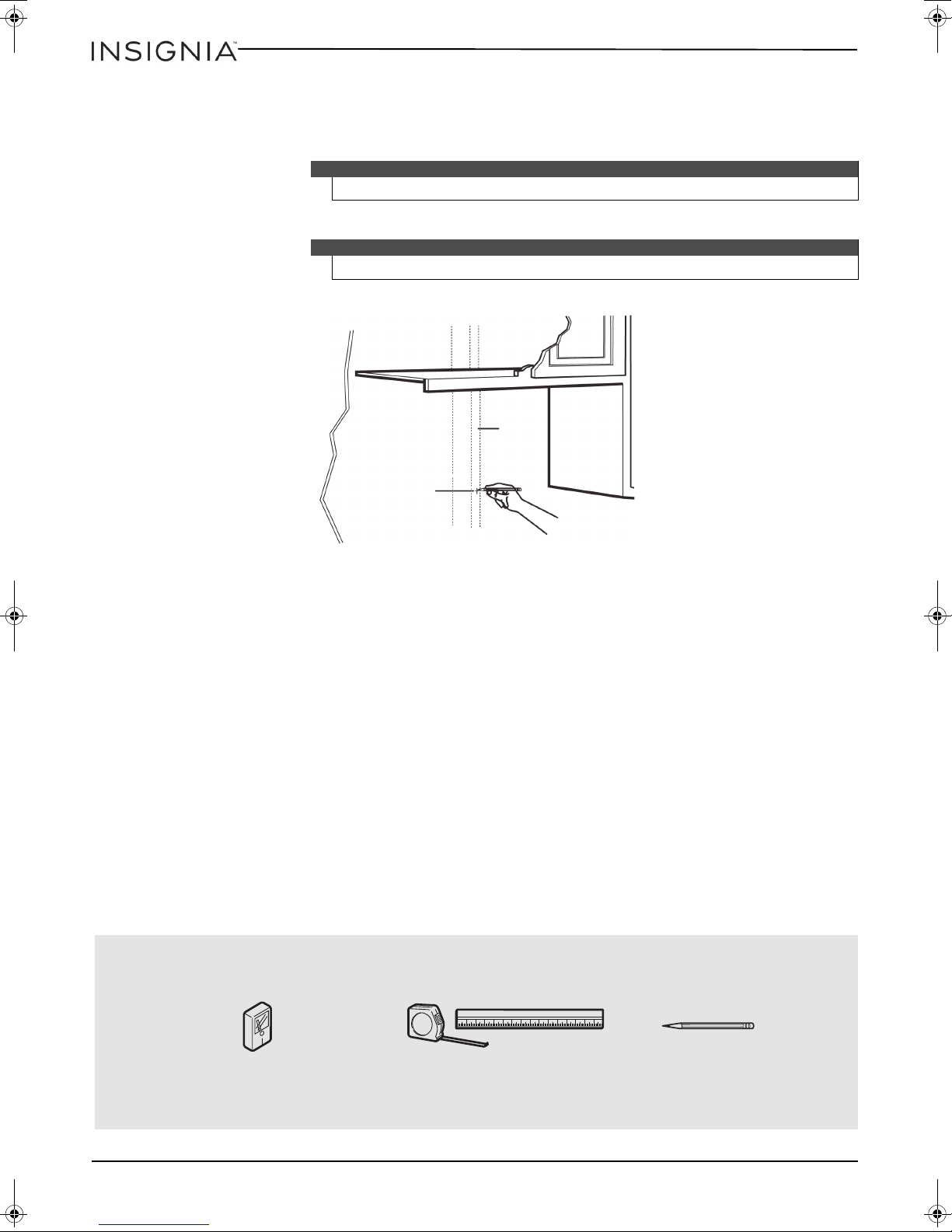
Step 1: Find the wall studs
Warning
Your microwave must be connected to at least one wall stud.
1 Using an edge-to-edge stud finder, locate the edges of the wall stud(s) within the opening.
Warning
The center of any adjacent wall studs should be 16" or 24" from this mark.
2 Mark the center of each stud, and then draw a vertical line down the center of each stud.
NS-OTR16SS8Q
You’ll need:
10
www.insigniaproducts.com
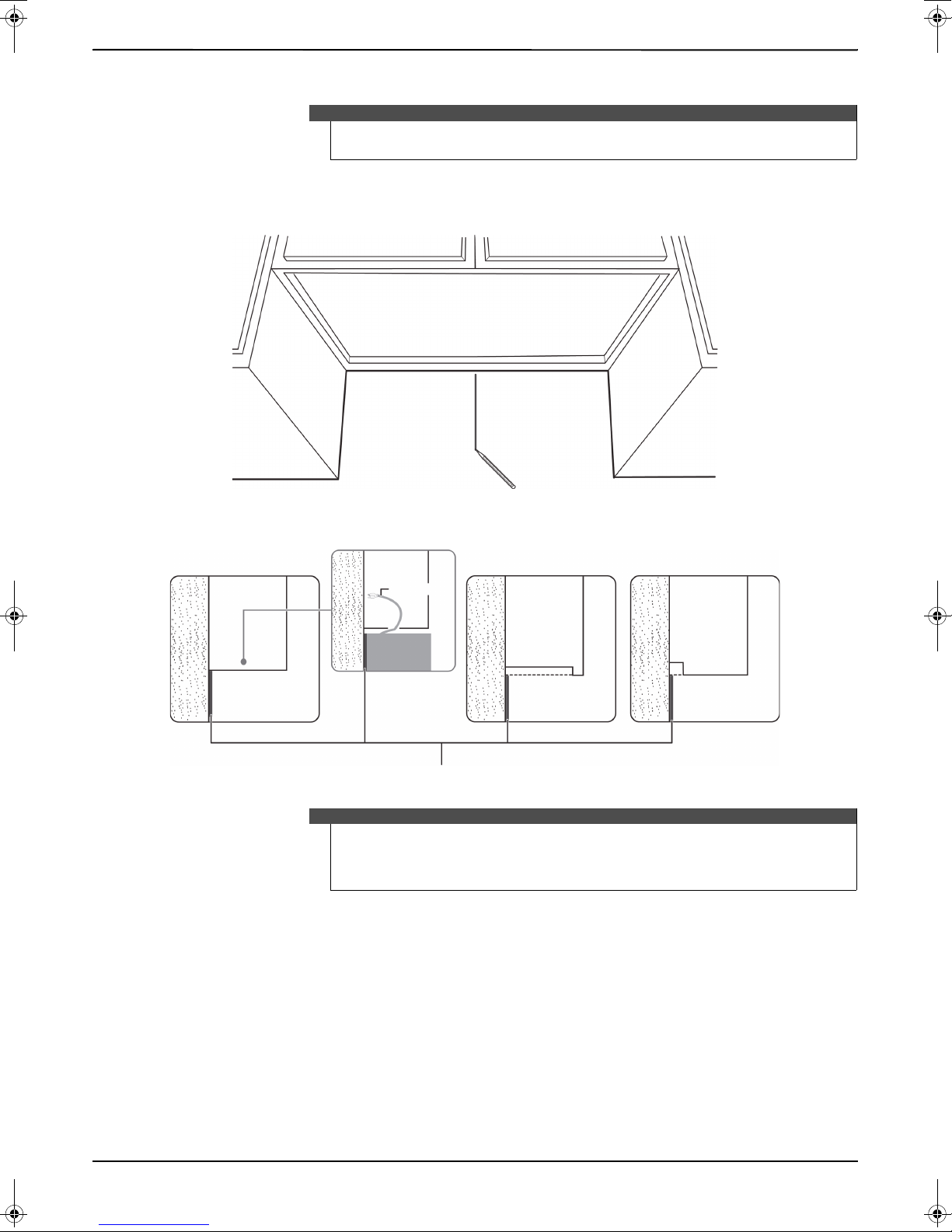
Step 2: Align the rear wall template
Rear wall template
Power cord
Cabinet
Cabinet
Cabinet
Cabinet
W
A
L
L
W
A
L
L
W
A
L
L
Flat bottom:
Front overhang:
Recessed back:
Notes
If the rear wall template is damaged or unusable, measure and mark the wall with
the dimemsions at the end of this step.
1 Use a level to make sure that the bottom of the cabinet is level.
2 Draw a vertical line down the center of the wall in the mounting space. This is where the center of your template
will be.
1.6 Cu. Ft. Over-the-Range Microwave
3 Draw a horizontal line at the height of the front of your cabinet. This is where the top of your template will be. If
the bottom of your cabinet is flat, make sure that you leave space for the power cord.
Notes
• If installing the microwave beneath smooth, flat cabinets, make sure that you
leave enough space for the power cord clearance.
• If cabinets have decorative trim that interferes with the microwave installation,
remove the trim to install the microwave properly and to make sure that it is level.
4 Trim the rear wall template along the dotted line.
www.insigniaproducts.com
11
NS-OTR16SS8Q
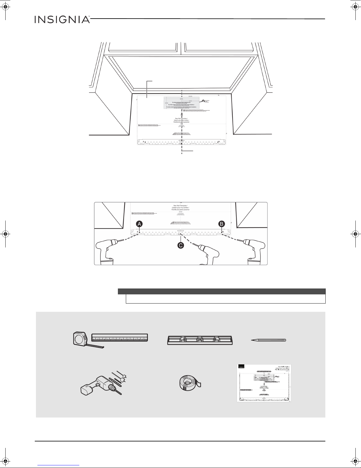
Vertical line in the center
Top of the template aligned
with the horizontal line
Note: Depending on your stud locations, your installation may look
different. You should mount to at least one stud.
Rear wall template
Pencil
Duct tape
Electric drill with 3/16” and 5/8” bits
Level
Ruler or tape measure
5 Tape the template in place so that it is centered on the vertical line and the top edge is aligned with the
horizontal line.
6 Mark points A and B on the wall with a pencil.
7 If the stud is on the center line, mark point C on the wall with a pencil.
OR
If the stud is not on the center line, mark two holes on either side of point C that align with the studs.
8 Drill holes through the template at points you marked. If the hole lines up with a stud, drill a 3/16” hole.
Otherwise, drill a 5/8" hole for the toggle bolts.
Notes
You’ll need:
12
At least three holes must be used for mounting.
www.insigniaproducts.com

Step 3: Select a ventilation type
Adapter
Note: If a wall stud is within 6 in.
(15.2 cm) of the vertical center
line, you cannot use this
installation option.
*Requires a charcoal
filter (included)
This microwave is designed for three types of ventilation. Select the type of ventilation you want to use, then go to
the corresponding page.
Note
This microwave is shipped assembled for top exhaust ventilation.
Option A - Outside top exhaust (vertical duct): See page 14
Option B - Outside back exhaust (horizontal duct): See page 22
1.6 Cu. Ft. Over-the-Range Microwave
Option C - Recirculating (non-vented/ductless): See page 32
www.insigniaproducts.com
13
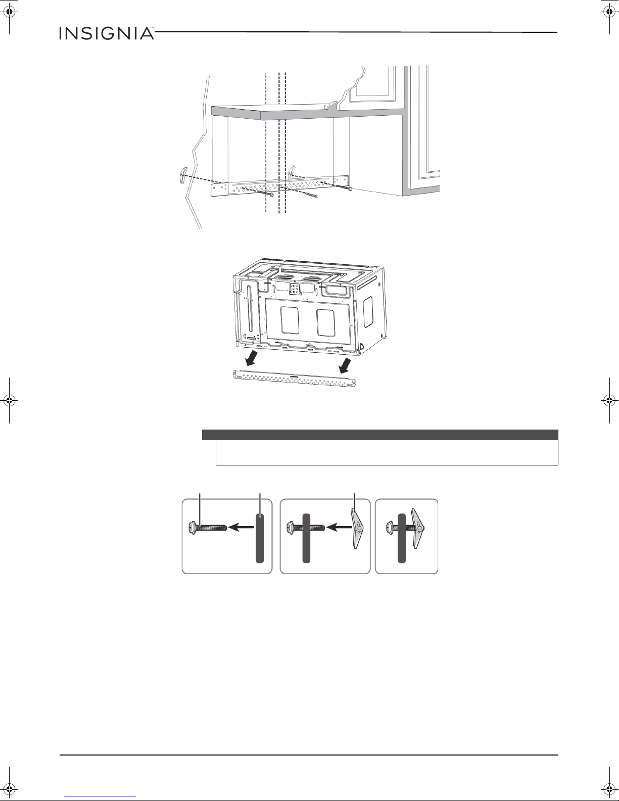
Step 4: Option A - Attach the mounting plate to the wall
Note: Depending on
your stud locations, your
installation may look
different. You should
insert toggle bolts into
drywall and wood screws
into studs.
Bolt
Wing
Mounting plate
1 Remove the rear wall template.
2 Remove the mounting plate from the back of your microwave using a #1 Phillips screwdriver.
NS-OTR16SS8Q
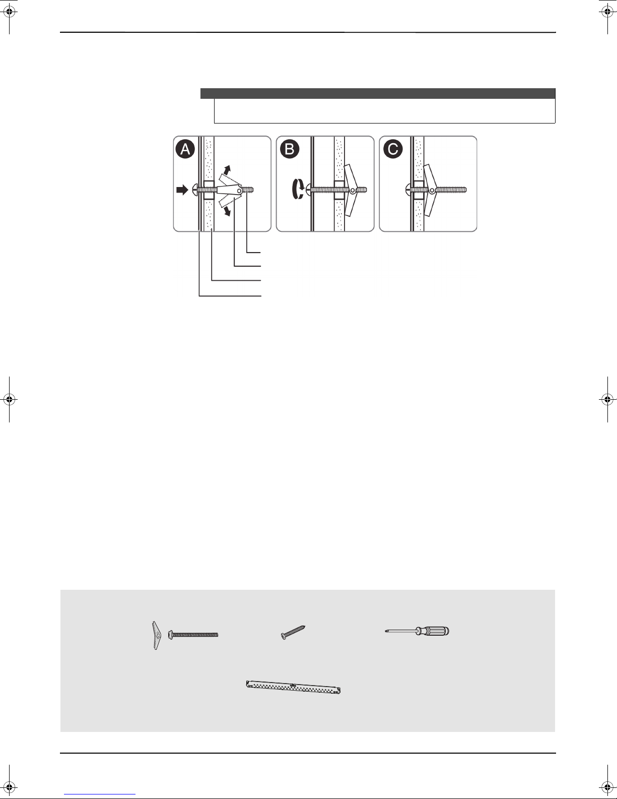
3 Insert the toggle bolt(s) through the front of the mounting plate into the hole(s) that are not going into a stud,
and then attach the toggle wings ¾" onto each bolt. Hold your mounting plate up to holes in your wall to
identify the correct position.
Note
The top of the mounting plate is indicated with an arrow. The mounting plate’s
hooks are on the front.
4 Place the mounting plate against the wall and insert the toggle wings into the holes you drilled in the drywall.
Pull the mounting plate away from the wall to help tighten the toggle wings.
14
www.insigniaproducts.com
1.6 Cu. Ft. Over-the-Range Microwave
Mounting plate
Wall
Tog gle win g
Toggle bolt
Wood screws
Mounting plate (Qty. 1)
(ships attached to microwave)
Toggle bolts
Phillips screwdrivers
5 Insert wood screw(s) through the mounting plate and into the hole(s) drilled in the stud(s), then tighten both the
wood screw(s) and toggle bolt(s) with a Phillips screwdriver to mount the plate. Make sure that the plate is
centered before tightening fully.
Caution
Be careful to avoid pinching your fingers between the back of the mounting plate
and the wall.
You’ll need:
www.insigniaproducts.com
15
 Loading...