

Insignia INS8058L Installation Manual
insigniarange.com Last Modied:27/01/2017
INSTALLATION MANUAL
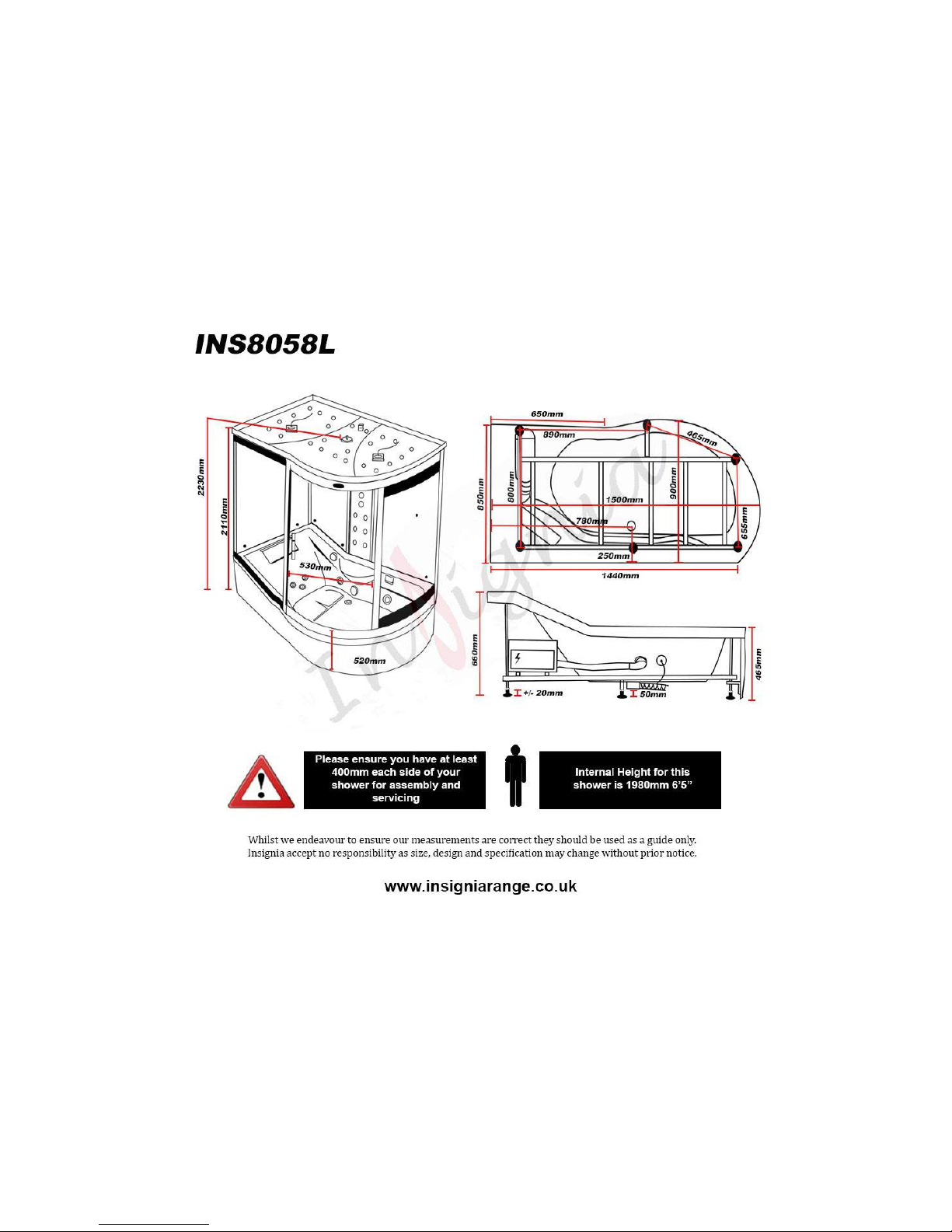
INS8058L
ATTENTION INSTALLERS:
These instrucons must be
le with the customer
30 Day Technical Support: 01908 226545
(NOTE: This service is only available to customers from the day of deli very,
please have your supplier’s details and your postcode to hand be fore calling)
Replacements Parts: inside of your warranty contact:
www.insigniarange.co.uk/customerService.aspx
Spares/Replacements Parts: outside of your warranty
contact 0844 800 3069
www.insigniarange.co.uk
WARRANTY REG NO: __________________________
To claim your full 5 year warranty, register your shower within 90 days of delivery at: www.insigniarange.co.uk/
warrantyreg.aspx. Standard 12 month warranty applies if outside this me period.
CHECK ALL CONTENTS BEFORE BUILD COMMENCES. NO RETURNS CAN BE MADE
ONCE THE BUILD HAS STARTED AS IT IS DEEMED ACCEPTANCE OF PRODUCT!
insigniarange.com Last Modied:27/01/2017
02
Thank you for your recent purchase of an Insignia shower. Please read this booklet with great care to ensure you get the best out of your build and have a shower that
will last for many years to come!
OUR BADGE RATING IN TERMS OF DIFFICULTY OF ASSEMBLY IS BASED ON CLIENT FEEDBACK
1 Badge = Very easy
2 Badges = Easy
3 Badges = Moderate
4 Badges = Harder than average
5 Badges = Professional skills required
This shower is rated 5 Badges

insigniarange.com Last Modied:27/01/2017
03
Contents
Introduction
Electrical Requirements
What’s In The Boxes?
Screw Pack Contents
Plumbing Requirements
Schematics
Starting The Installation
Electric Box Connections
Steam Generator Connections
Sealing and Water Testing
SUN Control Panel Instructions
Help Book Information
Parts list
2
5
7
8
9
10
11
22
23
27
28
31
32

insigniarange.com Last Modied:27/01/2017
04
ASSEMBLY AND PLUMBING
THIS PRODUCT BUILD IS RATED SUITABLE FOR DIY PURPOSES PROVIDING THE CUSTOMER IS OF ABOVE AVERAGE SKILL AND FEELS CONFIDENT IN
THEIR ABILITY. ONLY YOU THE CUSTOMER WILL KNOW THIS SO BEFORE ANY ATTEMPT IS MADE TO ASSEMBLE, READ THROUGH THE FOLLOWING
PAGES IN DETAIL THEN DECIDE. IF YOU HAVE ANY DOUBT USE THE SERVICES OF A PROFESSIONAL. IN PICKING SUCH, ALLOW THEM TO DECIDE IF
THEY ARE CAPABLE OF BUILD BY FIRST SHOWING THESE INSTRUCTIONS TO THEM. ALWAYS GET THREE QUOTES.
REMEMBER THE BEST IS NOT ALWAYS THE CHEAPEST!
REMEMBER PLUMBERS PLUMB! 90% OF THIS JOB IS NOT PLUMBING!
DUE TO THE NATURE OF THIS PRODUCT WE HIGHLY ADVISE THE PURCHASE AND FITTING OF A WATER SOFTENER
(PLEASE NOTE LIMESCALE BUILD UP MAY CAUSE DAMAGE TO YOUR SHOWER AND WILL NOT BE COVERED UNDER WARRANTY)
ELECTRICAL CONNECTION TO HOUSE MAINS
WHEN YOUR ITEM IS ASSEMBLED ALWAYS USE THE SERVICES OF A FULLY QUALIFIED ELECTRICAN COMPANY TO COMPLETE THE CONNECTION FROM
SHOWER TO THE HOUSE SUPPLY. LAWS DEMAND IN MANY CASES YOU DO THIS AND YOUR WARRANTY IS VOID IN REGARDS TO THE ELECTRICAL
ITEMS IF THIS IS NOT UNDERTAKEN.
YOURS AND OTHERS SAFETY IS PARAMOUNT. NEVER ATTEMPT THIS YOURSELF!
REMEMBER:
These showers are designed to be free standing and movable from their location should you have the need to replace anything. ALWAYS USE Flexible braided water
inlet pipes (not supplied) at least a metre long (not central heating plastic type!)
Always use a flexible waste pipe from your house supply to the shower .
NEVER FIX with rigid pipes, NEVER FIX the unit to the wall.
DURING BUILD, LIKE ALL SHOWERS CORRECT SEALING IS IMPERATIVE.
If you are using Insignia’s RubberGum, please ensure the product does not come in contact with your silicone as this will cause the RubberGum to fail and
will not adhere as intended.
ATTENTION
ALWAYS FIT EASY TO GET TO ISOLATION TAPS ON BOTH THE HOT AND COLD WATER SUPPLY (NOT SUPPLIED). JUST LIKE A
DISHWASHER OR WASHING MACHINE, THIS PRODUCT MUST BE ISOLATED WHEN NOT IN USE.
FLEXIBLE SUPPLY HOSES (NOT SUPPLIED) COUPLE HERE AS ORIGIN OF SUPPLY

insigniarange.com Last Modied:27/01/2017
05
TOTAL ELECTRICAL REQUIREMENTS
Voltage Rating 220 -240AC
Frequency Rating 50HZ
Power Rating 2.8KW
Your electrical contractor should understand ALL legal requirements of connection before undertaking any work or installation.
UNDER NO CIRCUMSTANCES UNDERTAKE THIS YOURSELF!!!
Note for electrician. This product comes with 13 amp plug(s) fitted with an RCD unit. We leave it this way for you to connect this your own way
due to continued additions to current regulations. As at October 2010 we offered two methods.
1) Connect within current laws and IP directives using plug and RCD provided with steam version or supply one for non steam version
2) (Preferred) Wire into isolated fused feed connecting directly to the house consumer/service box. Remove the fitted plug and ensure the Con-
sumer unit has capabilities to replace RCD feature if RCD is removed.
Always use protection against electrical surge. Your shower should be treated the same as a home computer. A surge protector should eradi-
cate the possibility of either the transformer or computer control being burnt out. Please note earth is required and found on chassis of shower
tray. A further earth is required from Steam Generator unit. Each earth must ground through power supply line.
insigniarange.com Last Modied:27/01/2017
06
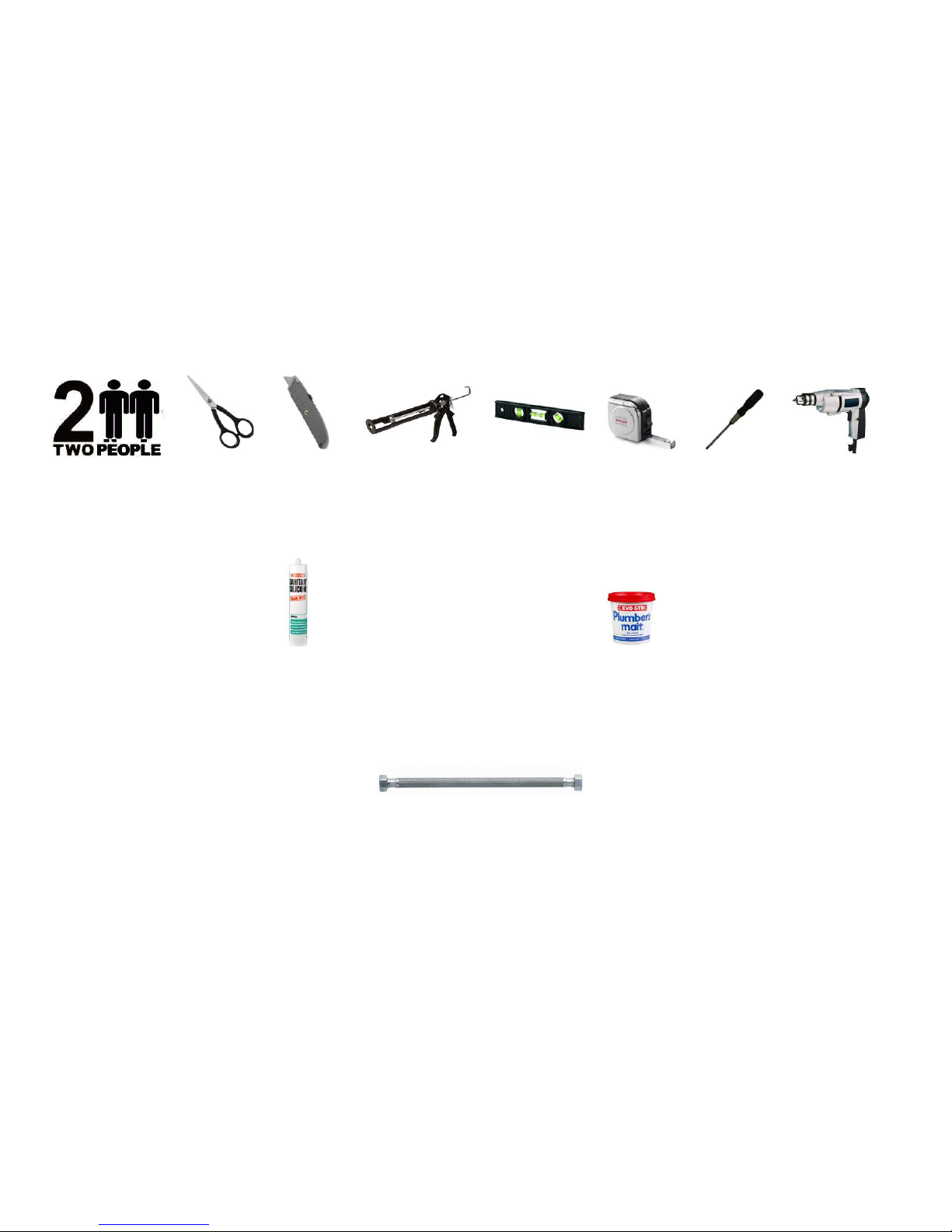
Tool Requirements
None Supplied
Scissors Stanley Blade Silicone Gun Spirit Level Tape Measure Philips Screwdriver Electric Drill
Adhesive Requirements
Hardware Requirements
Bacteria Resistant Sanitary Silicone - (for vertical joints) Plumbers Mait (for waste joints)
A Steam Shower requires 3 x 1 Metre Braided Hose
Not Supplied
Not Supplied Not Supplied

insigniarange.com Last Modied:27/01/2017
07
Whilst the next steps show you how to assemble your shower we want to make sure you have a correct build to ensure you get a trouble free shower. Therefore our advice
is to follow the instructions and perform a dry run to ensure you are confident with the build and you understand fully how t he unit is assembled. When we use the word
“DRY RUN” this means you do not silicone anything, just simply construct the shower, align, drill and screw everything together. Once y ou are happy with the build take the
unit apart and carry out the final fix.
What’s In The Boxes?
Tray Box
1x Tray
1x Roof
2x Curved Rails
2x Accessories Box
Glass Room
2x Door seals
1x Glass door
2x fixed glass
Column
1x Complete Column
Backwalls
1x Angled Panel Backwall
1x Square Panel Backwall
Side Panel
Glass Side Panel
In addition to above you will have all the required internal accessories to complete the shower

insigniarange.com Last Modied:27/01/2017
08
VERY IMPORTANT
Have you got everything? If not please contact the Insignia Support Line on 01908 226545. Remember NEVER book your tradesman until everything has arrived, been
checked and is present. No replacement/missing parts can be obtained free of charge during or after the build. Any claims can only be within the timescale permitted (48
hours after delivery) and always BEFORE build.
Insignia Screw Pack
VERY IMPORTANT
Have you got everything? If not please contact the Insignia Support Line on 01908 226545. Remember NEVER book your tradesman until everything has arrived, been
checked and is present. No replacement/missing parts can be obtained free of charge during or after the build. Any claims can only be within the timescale permitted (48
hours after delivery) and always BEFORE build.
Product Code Descripon Quanty
SP097 Door Handles 1
SP011/012 Door Wheels 2 each
ST20 20mm Screws 20
ST35 35mm Screws 10
ST14 14mm Screws 6
ST25/PCH13/CPC16/B22 Various 14 each
BAG Chrome Brackets 12
DB61 Drill Piece 1

insigniarange.com Last Modied:27/01/2017
09
Pressure Requirements from your house supply
We recommend a bar pressure between 2.5 and 3.4 BAR. If you have a combi boiler system no problem should be experienced. If you have a gravity feed older type
installation (hot water tank type usually less than 1 bar) you will almost certainly need a pump. We cannot advise on which t ype of pump is used, location or design because
all house plumbing layouts vary. This is a job for your installer/plumber. The end delivery however must fall within the scop e above.
Important Note Do n ot exceed 3.4 BAR pressu re u nder any ci rcumstan ces. War ran ty is voi d i f s o as d amag e will o cc ur. If you h ave a c ombi s up ply, pl ease u se a
pressure reducing valve if required to lower the BAR pressure to the shower.
Please Remember that this product is free standing and is designed to be pulled away from the wall.
The waste hose must be of a flexible type (1m flexible waste supplied).
The water supply pipes need to be at least 1 metre in length and must be that of a flexible braided type (not supplied).
DO NOT OVERTIGHTEN THE BRAIDED HOSES AS IT CAN CAUSE THE CONNECTION TO POP AFTER A FEW WEEKS OF USE
insigniarange.com Last Modied:27/01/2017
10
insigniarange.com Last Modied:27/01/2017
11
TO START
Make sure you have a clear space, remember when finished and in place you need access
to check your build and able to pull the shower out for servicing or should you have the need
to replace anything!
Take the shower tub and remove all the protective wrapping and fit the waste. In the side of
the waste supplied in the optional fitting kit you will notice a spigot not seen on an ordinary
waste. In most cases this is blanked yet should you have a steam version you need to gently
drill this out as this item is for the steam generator drainage and will be connected in the
instructions later.
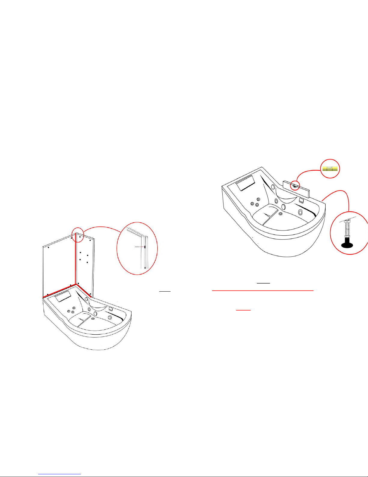
Now please level the tray by firstly placing the tray in its final location and then using a spirit
level, adjust the tray feet accordingly. Once you are happy with the levelling of the tray, you
can pull it out to begin the main construction.
Step 1
Once you have successfully completed a dry run,
Then continue to place the separate side panels onto the bath, screw together the
angled back piece and the side panel using the ST14 screws x4
We advise to run a bead of silicone along the vertical edge in-between the two back
panels and in-between.
Step 1
insigniarange.com Last Modied:27/01/2017
12
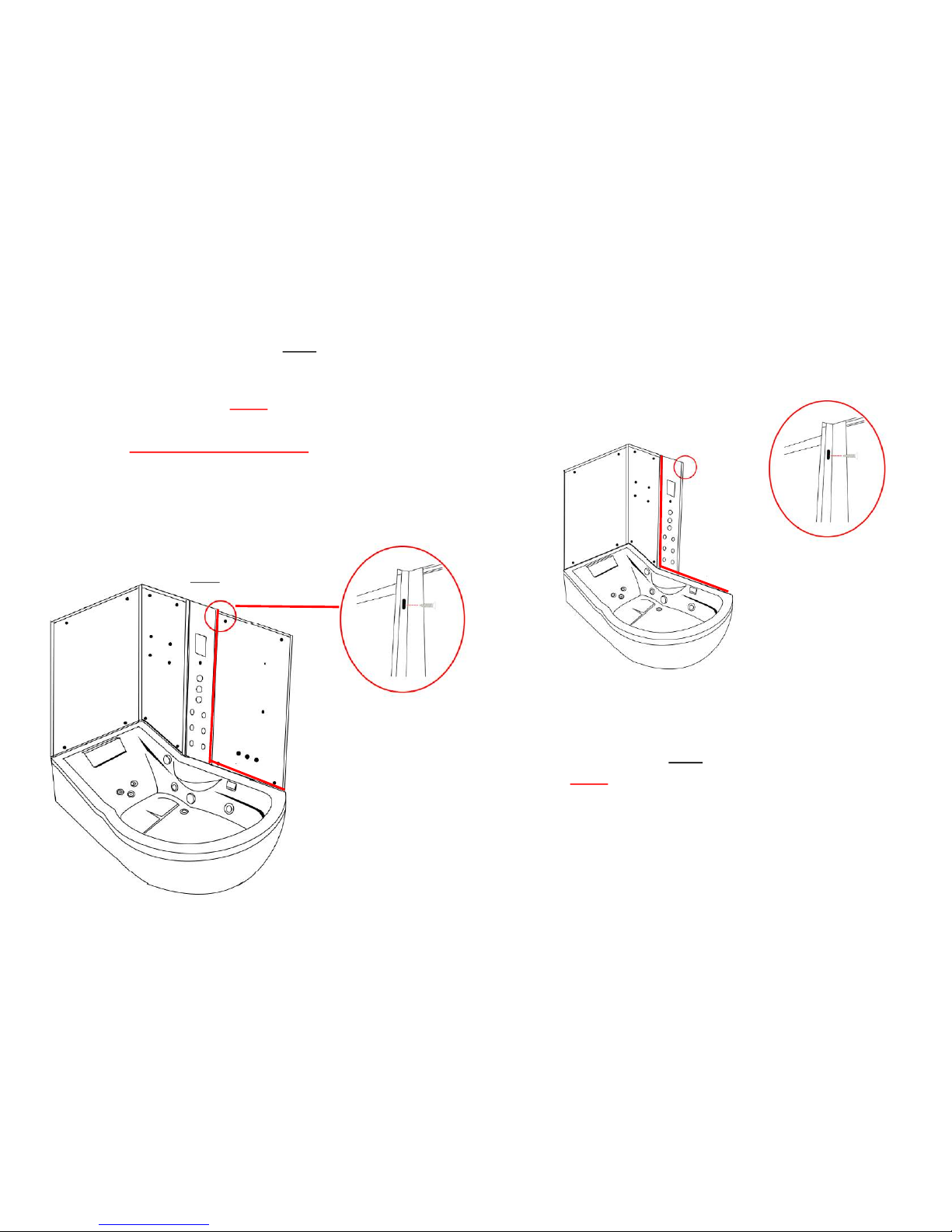
Step 3
Apply silicone to the specified area’s as shown and now fix
together and screw the large back glass panel to the column using the ST20 screws.
Step 2
(please note, if your column has a rubber seal at the bottom , take the rubber off
and apply silicone inside the rubber and replace)
Again, Once you have completed a dry run and are happy, Then continue to apply
the silicone to the specified area of the control column and place next to the angled
back glass panel and fix together using the ST20 screws.
Step 2
Step 3
insigniarange.com Last Modied:27/01/2017
13
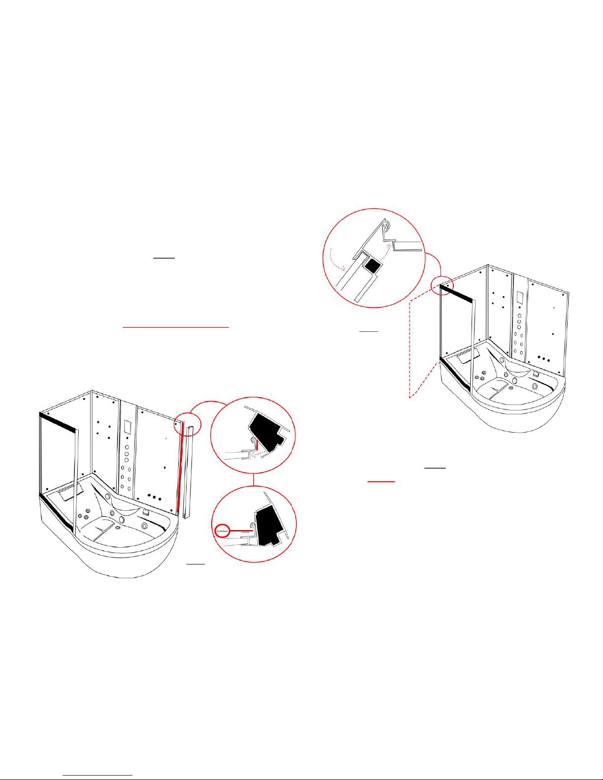
Step 5
Silicone sp eci fi ed as sho wn in d iag ram .
Next using the angled upright, place this to the rear squared glass panel by follow-
ing the position shown in the image marked “1”
Now move the angled upright in the direction as shown in image “1” until this is into
place as shown in image “2”
Once you are happy with the alignment then continue to screw the upright into
place at the top and bottom using ST14’s
Please note: These are not pilot holed and you will need to use the DB6
1
2
1 2
1
2
Step 4
Now lock the front angled glass panel to the side glass panel by following
the position shown in the image marked “1”
Once you have met the back panel inside the front upright as per the close
up image walk the panel around to the position shown in the image
marked “2”
NOTE: Do not apply silicone until Step 6
Step 4
Step 5
insigniarange.com Last Modied:27/01/2017
14
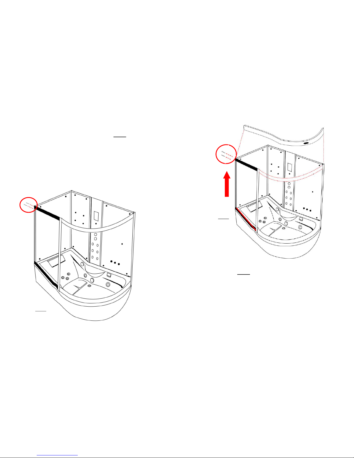
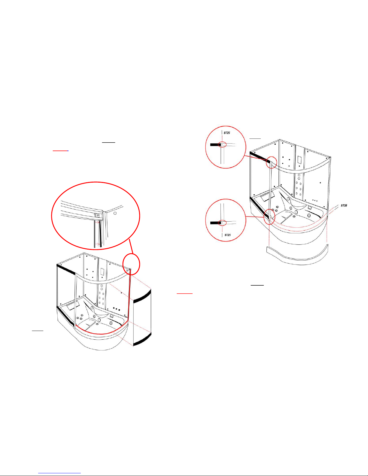
Step 6
Lower the top curved rail into position and screw from the rear side as per the image
using the ST35 screws.
Fix the front of the top curved rail onto the upright of the front fixed angled glass. Please
note in order to do this you will need to slide up the front fixed panel roughly 3 inches to
expose the screw holes.
Step 7
.
Then using ST35 screws fix the top rail to the opposite upright as demonstrated in the
following diagram
Step 6
Step 7
insigniarange.com Last Modied:27/01/2017
15
Step 8
Now apply silicone to the bottom of the remaining curved rail and place into position as
shown in the diagram and fix this into place using the ST35 screws and ST25 screws
Please note that when drilling the holes to take the screws this is at a depth no deeper than
5mm.
Step 9
Apply silicone to specified area as shown on the diagram, then take the front curved glass panel
and insert into the upright. Then using the flat rubber seal insert in between the glass and
upright.
NOTE:
(It’s common that the curved glass once is position may not fit completely snug against the rail
due to alignment. This is normal and is rectified by the use of a silicone seal)
Step 8
Step 9
insigniarange.com Last Modied:27/01/2017
16
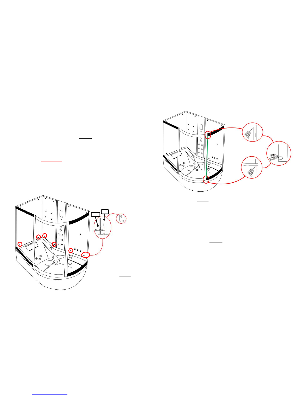
Step 10
Insert remaining upright to the left of the curved glass panel. Drill and screw this
into position using the ST20 screws and once fixed slide the flat rubber glass seal into
this newly fitted upright on the inside (as of the green line in the image)
Please Note: en su re you d ri ll no deeper th an 5mm.
Step 11
Pierce through the holes using a screwdriver to show pre-cut holes in the glass as
indicated in the image. Now using the chrome “L” brackets, fix these to the outside of the
glass panels using the provided nuts and bolts (B22) please ensure the bolt goes
through the plastic cover holder (PCH13) first
Align the shower panels until you are happy with the sitting of these and now using the
ST25 screw s, screw th e bracket s t o t he tub
Now place the Chrome cover caps (CPC16) onto the cover holders (PCH13)
Step 10
Step 11
Back
Inside
insigniarange.com Last Modied:27/01/2017
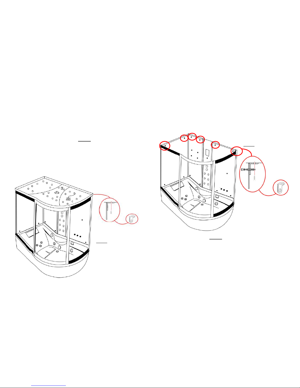
17
Step 12
Pierce through the holes using a screwdriver to show pre-cut holes in the glass as
indicated in the image. Now repeat the process from step 11 to secure the roof to the
glass panels
Step 13
Align the shower roof to your side panels and when you are happy with the
alignment of the roof, use the ST14 screws to screw this into place
Step 12
Step 13
insigniarange.com Last Modied:27/01/2017
18
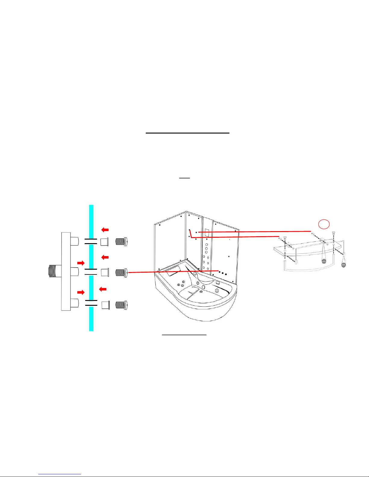
x2
Shelf
Fix the chrome floating shelf brackets to your glass back panel by using the provided screws. Now attach the chrome tubed bar s to your glass shelf as illustrated in the
below image. Next slide the shelf into your shelf brackets and secure by tightening the grub screw situated on the bottom of the bracket.
Accessory Installation
Tri-Jet Steam System
Locate the three holes in the glass panel. Put the Tri-Jet manifold (as shown) through and screw the three small outlets to it.
Please Note
Ensure all grey backing film on the rear of the glass panels are pierced through the existing glass holes with a knife to provide an efficient smooth fitting and location of the
accessories. We recommend using a screwdriver on the smaller holes.
insigniarange.com Last Modied:27/01/2017
19
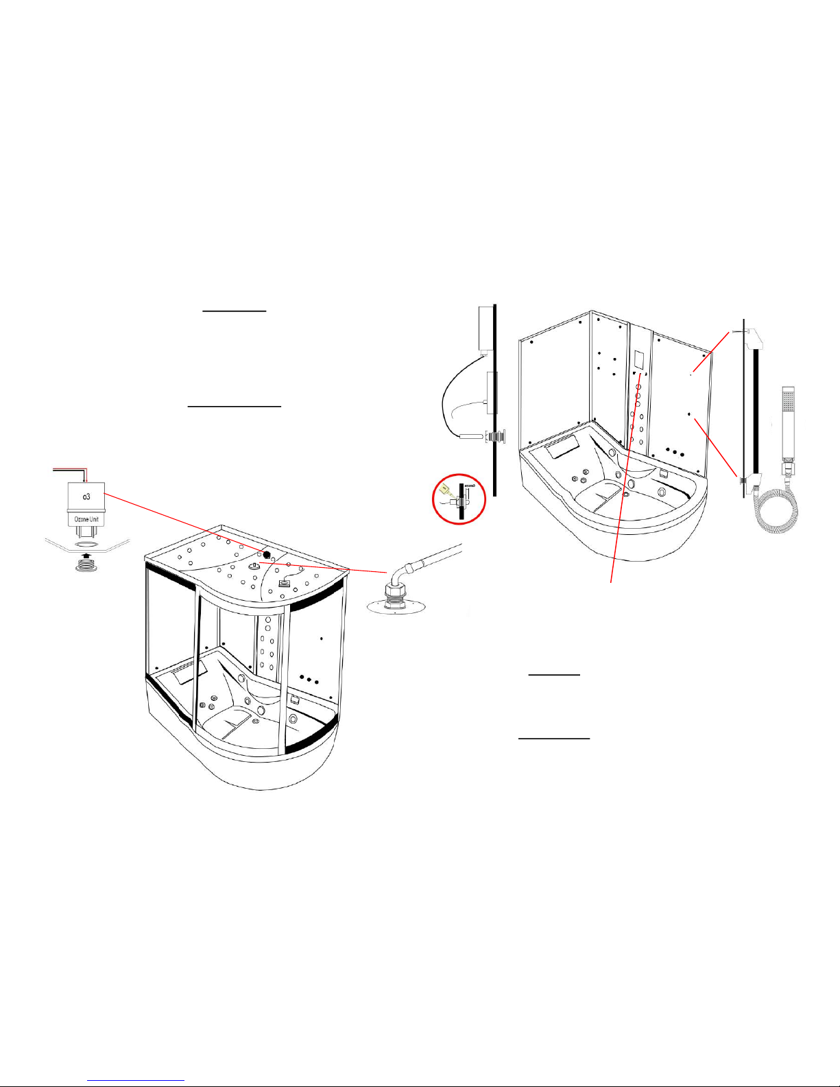
Hand Shower
Attach the chrome riser bar to the glass wall ensuring the water inlet is inserted
through the lower large hole and hand tightened from the rear side.
Now tighten the chrome shower holder ensuring that this will take the hand shower
itself without falling (please note over tightening will prevent the holder from sliding up
and down)
Thermostatic Probe
Insert the probe into the hole situated below the control panel roughly 6mm into the
cabin and run clear silicone around the rear side of the probe
Ozone (o3)
Unscrew the chrome pepper pot end and drop the white box upside down into the
rear hole as shown in the image. Now from the inside of the shower re -attach the
chrome pepper pot end and tighten.
Monsoon Head
Attach the grey hose from your valve to the inner black tube using PTFE tape
(please note this only needs to be hand tight. Over tightening will snap/damage the
inner black tube)
Please see your AMI system installaon guide for further details
insigniarange.com Last Modied:27/01/2017
20
Door Seals
Magnetic Seal: Push the magnetic door seal on the handle side of the glass door ensuring this is
tightly fitted.
Rear Door Seal: Place the rear door seal on the opposite side to the magnetic strip ensuring the flap
is facing the fixed glass panel
Handle
Ensuring that the inner thread is protruding out from the handle far enough, place the handle on the
outside of the door and secure by tightening the inner chrome knob to the protruding inner thread
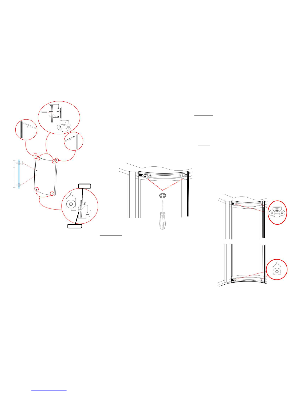
Door Wheels
Fit the adjustable wheels to the top and bottom of the glass doors and ensure the wheels are facing towards the
rail then hang the top wheels on to the top inner curved rail.
Now on the bottom wheels please push the button to lower the wheel for ease of installation and push the
wheel into the bottom curve rail. Once you are happy that the wheel is in the track, depress the button and allow
the wheel to enter therefore ensuring a secure a tight fit. Next adjust the top wheels by turning the screw
clockwise in which in turn will pull the wheels towards the track ensuring a secure a tight fit.
Now grease the track to ensure a smooth and long lasting operation (not supplied)
Outside
Inside
 Loading...