

Innovate Motorsports XD-16 User Manual

XD-16 Digital Universal Dash Display
User Manual
XD-16_Manual_1.4.doc

1. Overview......................................................................................................................................................... 3
2. The XD-16 Device .......................................................................................................................................... 3
The XD-16 Module................................................................................................................................................. 3
2.1. Identifying the user interface features of the XD-16 ................................................................................... 4
3. Mounting and Connecting the XD-16 ............................................................................................................. 4
4. Changing the channel display ........................................................................Error! Bookmark not defined.
5. Using the XD-16 ............................................................................................................................................. 5
6. Programming the XD-16................................................................................................................................. 6
6.1. Installing the LM Programmer Software...................................................................................................... 6
6.2. Connecting the XD-16 device to the computer........................................................................................... 7
6.3. Updating the Firmware................................................................................................................................ 7
6.4. Selecting the display channel ..................................................................................................................... 9
6.5. Programming the Min/Max hold functions ................................................................................................ 10
6.6. Programming the Warning/Alarm function................................................................................................ 11
6.7. Programming the Analog ‘needle’ colors.................................................................................................. 13
7. Changing the gauge face of the XD-16........................................................................................................ 14
7.1. Installing the new gauge face ................................................................................................................... 14
7.2. Create a custom label............................................................................................................................... 15
7.3. Assembly sequence of the XD-16 with foil face........................................................................................ 15
Appendix A: Specifications .................................................................................................................................. 15
Appendix B: Kit Contents..................................................................................................................................... 16
Appendix C: Limited Warranty............................................................................................................................ 17
Revision History....................................................................................................................................................... 18
- 2 -
1. Overview
The XD-16 is a programmable digital display used as dash mounted instrument for the Innovate Motorsports
sensor devices. The XD-16 fits into a standard 52mm (2-1/16”) gauge hole. Multiple XD-16’s can be daisychained to build and entire programmable dash. XD-16 gauge faces can be user customized. The XD-16 can also
be used to initiate and control recording on the LM-1 or other Innovate Recording devices, can initiate free air
calibration for Innovate Motorsports wideband controllers and indicate wideband controller status.
In addition the XD-16 can be programmed to hold minimum/maximum values of the displayed channel and
provide warnings/alerts depending on programmable warn conditions.
2. The XD-16 Device
The XD-16 set contains the following parts:
The XD-16 Module
- 3 -

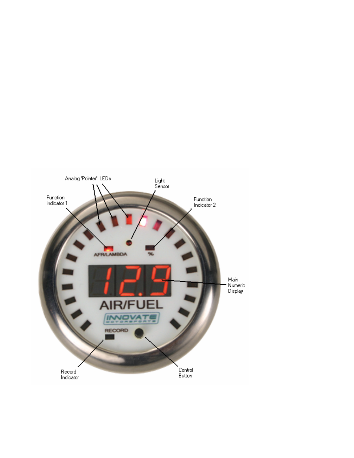
2.1. Identifying the user interface features of the XD-16
The analog pointer LED’s (21 total) act as a digital needle. The range and individual colors of this “needle” is
freely programmable.
The Function indicators 1 and 2 are used to indicate between % display (heater warm-up or O2 content) when the
XD-16 is programmed as AFR/Lambda display (default). When used to display other channels, the indicators can
be used to indicate the sign of the displayed value. By using the indicators as sign display (positive or negative)
one of the three numerical displays is not wasted to show a ‘-‘ sign. This functionality is programmable.
The main numeric display shows the numeric value of the displayed channel. When the XD-16 is used as
AFR/Lambda display it will also show the status of the wideband controller.
The light sensor allows the XD-16 to adjust its brightness to the light level of the environment. At night the full on
display would be much too bright and would interfere with the operation of the vehicle. During sunlight the XD-16
will go to maximum brightness to allow readability.
The Control Button is used to control various aspects of the XD-16 and attached wideband controller or recording
device like the LM-1.
The record indicator will blink when a LM-1 or other Innovate Motorsports recording product is attached and
actively recording.
3. Mounting and Connecting the XD-16
1. If not using a commercial gauge pod, cut a 52mm (2 1/16”) hole into the intended dash location.
2. Insert and mount the XD-16 and mount it with the included mounting bracket, leaving the XD-16 cables in the
back accessible.
3. Connect the RED wire from the back of the XD-16 to a switched 12V source in your car. A switched 12V
source goes on as soon as the ignition on the car is on or the engine runs. Make sure the connection is fused
with at least a 2A fuse.
4. Connect the BLACK wire to ground. The ground should be shared with other MTS devices (for example: LC-
1, DL-32, SSI-4, TC-4, LMA-3, etc…)
5. Connecting Signal Source:
5.1. If connecting to a LM-1, connect the LM-1 patch cable (P/N: 3759) to the LM-1’s Serial Port. Plug the
2.5mm male stereo end into the XD-16 Serial IN port (female 2.5 mm socket marked “IN”).
5.2. If connecting to an LC-1 or other MTS device, connect the male 2.5mm Stereo to male 2.5mm Stereo
cable between the Serial OUT port of the device to the Serial IN port of the XD-16. The rule is: LC-1s
first then LMA-3s, SSI-4s, and TC-4s. Then goes the DL-32 which is going to record the information
coming from the other products. Lastly, you connect your XD-16s which can be setup to display any
channel in the serial chain.
6. If using a computer to datalog or download LM-1 data, connect the XD-16 to Computer cable between the
Serial OUT port of the XD-16 and the computer’s serial port.
The following diagram show how to connect multiple Innovate Motorsports devices to form a logging and display
chain. The example chain consists of a LM-1, a LC-1, a LMA-3 and 2 XD-16’s. In this case the chain has 12
channels (6 from LM-1, 1 from LC-1 and 5 from LMA-3). If you are running LC-1s the rule is: LC-1s first then
LMA-3s, SSI-4s, and TC-4s. Then goes the DL-32 which is going to record the information coming from the other
products. Lastly, you connect your XD-16s which can be setup to display any channel in the serial chain.
- 4 -
4. Using the XD-16
When the XD-16 powers up it will briefly go through a sequence where it lights up all its LEDs. This is a function
and diagnostic test. Holding down the Control button during power-up will continue to light up all LEDs until the
button is released.
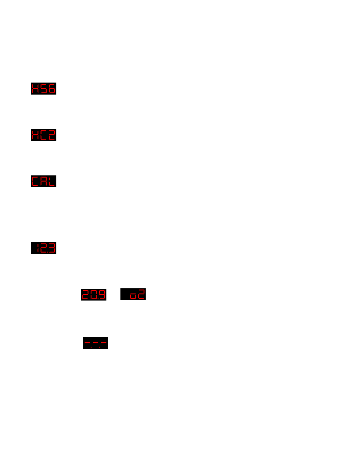
4.1. Sensor Warm-up
For example, this would indicate that he heater is warmed up to 56%. The Function Indicator 2 is lit.
4.2. Heater Calibration
The last digit is the count-down of the heater calibration.
4.3. Free air calibration in process
When shown steady, free air calibration is in progress. If blinking and not going away after 5 seconds, the LM-1
requests a free air calibration as happens after a heater calibration.
Blinking CAL can also happen if the control button is pressed rapidly 3 times. Pressing it then again, initiates a
free air calibration. If this is unintentionally pressed, the CAL request goes away after 5 seconds.
4.4. Normal Operation
With function indicator 1 lit this shows AFR.
4.5. Normal Operation very lean mixture or free air
Switching between
Shows the free air content of the gas the sensor sees.
and
4.6. No Connection detected
If the display shows:
The XD-16 cannot receive data from the LM-1 or other devices. Make sure all the connections are fully seated.
4.7. Start/Stop Recording
Press the Control button once to start recording. The Record indicator light will blink.
Press the Control button again once to stop recording. The Record indictor will switch off.
4.8. Clear Recording Memory of LM-1
- 5 -
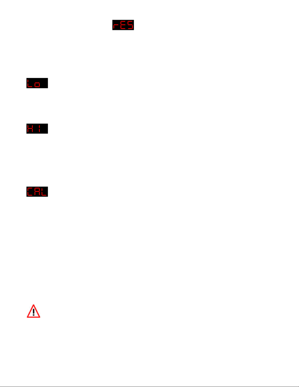
Press and hold the Control button until
for Reset shows.
4.9. Review Min/Max hold
Press the Control button twice rapidly. The XD-16 will show the last minimum value indicated. Note that the XD16 will remember the minimum value even if power is switched off.
Minimum value is indicated by alternating between:
and the minimum value stored.
Holding the Control button down for a few seconds while this is displayed will reset the minimum value.
Press the Control button instead only briefly will show the maximum value indicated. It is indicated by alternating
between:
and the maximum value stored.
Press the Control button again briefly to return to normal operation.
Holding the Control button down for a few seconds while this is displayed will reset the maximum value.
4.10. Initiating a free air calibration
Press the Control button three times rapidly. The display will show a blinking:
If the button was press accidentally three times, wait for 5 seconds. The XD-16 will return to normal display mode.
Pressing the Control button while the blinking CAL is displayed will initiate a free air calibration on ALL connected
wideband devices.
5. Programming the XD-16
You will need:
1. XD-16 to Computer cable (male 2.5mm Stereo to DB-9)
2. XD-16 Terminator plug (single male 2.5mm Stereo plug)
3. A laptop computer
4. When powered by the car, the ignition of the car must be on to power the XD-16. Alternatively you can power
the XD-16 with a suitable power source between 8V and 25V. A normal 9V battery can be used to power the XD-
16.
Always disconnect and connected the serial ports labeled IN and OUT with the unit OFF.
5.1. Installing the LM Programmer Software
Put the included CD in your CD-drive on your computer and follow the instructions on screen. The Software will
be installed including pre-set directories for log-data and downloaded software. The LM Installer also puts entries
for the LM Software in the Start-Menu of your computer under the heading ‘Innovate!’.
- 6 -
 Loading...