Innovate Motorsports MTX-L User Manual

MTX-L
Digital Air/Fuel Ratio Gauge
User Manual
 Warning!
The Oxygen Sensor used in this device gets very hot in operation.
Do not touch a hot sensor. Do not let a hot sensor touch a combustible surface. Do not use the sensor with or near flammable liquids or gases. Failure to heed these warnings may result in severe burns, explosions, fires, or other dangerous events.
When installed in the exhaust, the oxygen sensor MUST be connected and operating with the MTX-L whenever the car is running. An un-powered oxygen sensor can be quickly damaged when exposed to hot exhaust gases.
11-0129A
TABLE OF CONTENTS
1 |
MTX-L |
....................................................................................................... |
3 |
|
2 |
Installation ................................................................................................ |
4 |
||
|
2.1 |
Wiring ................................................................................................. |
4 |
|
|
2.1.1 ..................... |
Single Innovate Device Relay Wiring Instructions |
5 |
|
|
2.2 |
Mounting ........................................................................and Routing |
5 |
|
|
2.3 |
Sensor ..............................................................................Placement |
6 |
|
|
2.4 |
Sensor ..............................................................................Calibration |
7 |
|
|
2.4.1 .................................................................. |
Calibration Schedule |
8 |
|
|
2.5 |
Changing ................................the MTX-L’s gauge face and/or bezel |
8 |
|
3 Download ..........................................the Logworks 3 software package |
8 |
|||
|
3.1 |
Installing ...............................................................................software |
9 |
|
|
3.2 |
Connecting ..........................................................to LM Programmer |
9 |
|
|
3.2.1 .......................................................................... |
Analog Outputs |
9 |
|
|
3.2.2 ............................................... |
Advanced output programming |
11 |
|
|
3.2.3 ............................................................ |
Updating the Firmware |
11 |
|
|
3.3 |
Logging ................................data from your MTX-L with LogWorks |
12 |
|
|
3.4 |
Customizing ...............................................................your fuel type |
12 |
|
|
3.5 |
Customizing .......................................................your display range |
13 |
|
4 |
Wiring ...........................................................................Analog Outputs |
14 |
||
Appendix A: .......................................................................Limited Warranty |
15 |
|||
Appendix B: .........................MTX-L Error Codes and Troubleshooting Tips |
16 |
|||
2

1 MTX-L
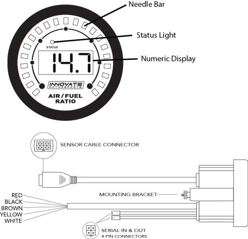
The MTX-L is an integrated gauge and controller for wideband AFR (lambda) measurements. Although it can be operated stand alone, it has digital I/O for integration with other MTS compatible products and two configurable analog outputs for integration with ECU’s and 3rd party data loggers. The following views will help you get familiar with the unit.
3
2 Installation
2.1Wiring
The MTX-L has 5 stripped wire ends:
1Connect the RED wire to an isolated switched 12V source in your vehicle. A switched 12V source goes ON as soon as “key on” power is active. The circuit to which you will pull power from should be able to support a 3 amp draw. Make sure this connection is protected with a 5A fuse.
 Circuits that share power with the vehicle’s stereo, ignition system, ECU, lighting, or fuel pump should not be used. When in doubt, create an additional circuit using an automotive relay available at any automotive parts supplier. See the next section for a relay installation diagram.
2The BLACK wire should be grounded to a solid ground source. The best possible ground source would be the battery ground (-) post.
 If other Innovate Motorsports devices are going to be daisy-chained along with the MTX-L, it is recommended that all devices be connected to a single ground point, ideally the battery ground (-) post.
3Connect the WHITE wire to a headlight power wire (a wire that supplies current to the headlights). This enables the display to dim for better nighttime viewing. DO NOT CONNECT THIS WIRE TO THE HEADLIGHT DIMMING WIRE. Connection to this rheostat type of switch will cause the gauge to malfunction. If you chose not to utilize the dimming feature, connect the WHITE wire to ground.
4Optionally, the YELLOW (Analog out 1) and/or BROWN (Analog out 2) can be connected to the analog inputs of other devices such as data loggers or ECUs. If either one or both of these wires are not being used isolate and tape the wire(s) out of the way. The default analog outputs are as follows: Analog output one (yellow) is 0V = 7.35 AFR and 5V = 22.39 AFR. Analog output two (brown) is 1.1V = 14 AFR and .1V = 15 AFR.
4

2.1.1Single Innovate Device Relay Wiring Instructions
2.2Mounting and Routing
The MTX-L gauge fits in any standard 2 1/16” (52mm) gauge pod. Mounting of the gauge should be done in such a manner that the cables are not being forcefully pulled and strained from the gauge itself. Route the sensor cable avoiding contact with the exhaust pipe and other hot sources that could melt the cable. Also avoid routing the sensor cable near ignition components or other sources of RF (radio frequency) and EMI (Electromagnetic interference) noise.
 The MTX-L gauge is splash resistant (not water proof) and can be mounted so that it is exposed to the outdoor elements. The MTX-L should not be submerged and special consideration should be taken to protect the gauge from direct water spray (water coming from a pressurized source.)
When replacing the bezel and/or gauge face verify that the o-ring is properly seated.
5
 Loading...