


LM-1

LM-1_Manual_3.4.doc
LM-1 Digital Air/Fuel Ratio (Lambda) Meter
Manual
Warning!
The Oxygen Sensor used in this device gets very hot in operation.
Do not touch the hot sensor. Do not let a hot sensor touch a
combustible surface. Do not use the sensor with or near flammable
liquids or gases. Failure to heed these warnings may result in severe
burns, explosions or fires.
When installed in the exhaust, the oxygen sensor MUST be
connected and operating with the LM-1 whenever the car is running.
An un-powered oxygen sensor will be quickly damaged when
exposed to hot exhaust gases.

- 2 -
1. Overview............................................................................................................................... 2
2. The LM-1 Instrument ............................................................................................................ 3
2.1. The LM-1 Instrument (Size: 7" x 4" x 1.5")...................................................................... 3
3. First Time Use ...................................................................................................................... 3
4. Installation............................................................................................................................. 4
4.1. Mounting the sensor using a Bung or Exhaust Clamp. .................................................... 4
4.2. How to fabricate a copper heat sink ................................................................................. 6
5. Operation.............................................................................................................................. 6
6. Calibration............................................................................................................................. 7
6.1. Free air calibration ............................................................................................................7
6.2. Sensor heater calibration.................................................................................................. 7
6.3. Calibration Schedule......................................................................................................... 7
7. Recording other vehicle data with the LM-1......................................................................... 8
7.1. Overview ........................................................................................................................... 8
7.2. Recording.......................................................................................................................... 8
8. Remote display of Lambda and/or AFR ............................................................................... 9
8.1. Analog Lambda/AFR instrument....................................................................................... 9
8.2. Special considerations when installing LM-1 permanently in the vehicle......................... 9
9. Programming the LM-1....................................................................................................... 11
9.1. Installing the LM Programmer Software ......................................................................... 11
Hooking up the LM-1 device to the computer............................................................................ 11
9.2. Resetting the calibration data ......................................................................................... 12
9.3. Updating the software (LM-1 firmware) .......................................................................... 12
9.4. Programming the analog outputs.................................................................................... 13
9.4.1. Advanced output programming................................................................................ 14
10. Tips, Tricks and Troubleshooting ....................................................................................... 15
10.1. General measurement requirements .......................................................................... 15
10.2. Vehicles with ‘smog-pumps’........................................................................................ 15
10.3. Measuring at the tail-pipe............................................................................................ 15
10.4. Single Cylinder Engines.............................................................................................. 15
10.5. Diesel Engines............................................................................................................. 15
10.6. Reference cell or Pump cell circuit open or shorted errors......................................... 15
10.7. Sensor Timing Errors .................................................................................................. 16
10.8. Other tricks .................................................................................................................. 16
10.9. Analog Output tricks/hints ........................................................................................... 16
11. Advanced Topics................................................................................................................17
11.1. Connecting the LM-1 to simulate a narrow band oxygen sensor................................ 17
12. Kit Contents ........................................................................................................................18
Appendix A: LM-1 Cable Pinouts .................................................................................................20
Appendix B: LM-1 Error Codes and Troubleshooting Tips .......................................................... 23
Appendix C: Limited Warranty...................................................................................................... 24
Revision History............................................................................................................................. 25
1. Overview

- 3 -
The LM-1 is a hand-held instrument used to measure the Air/Fuel Ratio (AFR) or Lambda for an
engine. For gasoline-driven engines, the theoretically optimal air fuel ratio is 14.7 pounds of air
for every pound of fuel. At this ratio, theoretically, all available oxygen in the air combines with all
available fuel. This ratio is called the stoichiometric ratio. Stoichiometric for different fuels are as
follows:
Gasoline 14.7
LPG (Propane) 15.5
Methanol 6.4
Ethanol 9.0
CNG 17.2
Diesel 14.6
The measurement Lambda is the actual air fuel ratio over the stoichiometric ratio. A Lambda
measurement of “1” equates to the air fuel ratio of 14.7 (for gasoline engines). When Lambda is
less than 1 the engine runs “rich”, i.e., unburned fuel exists in the exhaust stream. If lambda is
greater than 1 the engine runs lean, i.e., free oxygen (0
2
) is present in the exhaust. Depending on
the engine, maximum power is typically delivered when the engine runs slightly rich (for example
at lambda values of 0.8 to 0.9 for most engines). This instrument provides a means to measure
the actual air fuel ratio or lambda in the engine in operation directly from the exhaust. For this a
special wide-band oxygen sensor is used to measure the lambda value derived from the oxygen
content (or lack thereof) of the exhaust gases.
2. First Time Use
1. Verify that the included 9V battery is installed in the battery compartment on the bottom of the
instrument.
2. Connect the power cable to the LM-1 12V Power connector and plug the other end in your
cigarette lighter socket in your car. Note that the 9V battery is for powering the LM-1
electronics and display, but it cannot power the oxygen sensor. (The primary purpose for the
9V battery is to power the LM-1 when it is connected to a PC for data downloads). You must
have a 12V power supply available to power the oxygen sensor.
Note: The supply voltage to the LM-1 must not exceed 16V.
3. Do not connect the sensor yet.
4. Switch the meter on.
The display shows either:
when connected to 12V Power, or .
In the second case, switch the ignition of your car on.
5. Switch the meter off after 10 seconds.
6. Connect the sensor to the sensor interface connector. The sensor must be exposed to air for
the first time calibration.
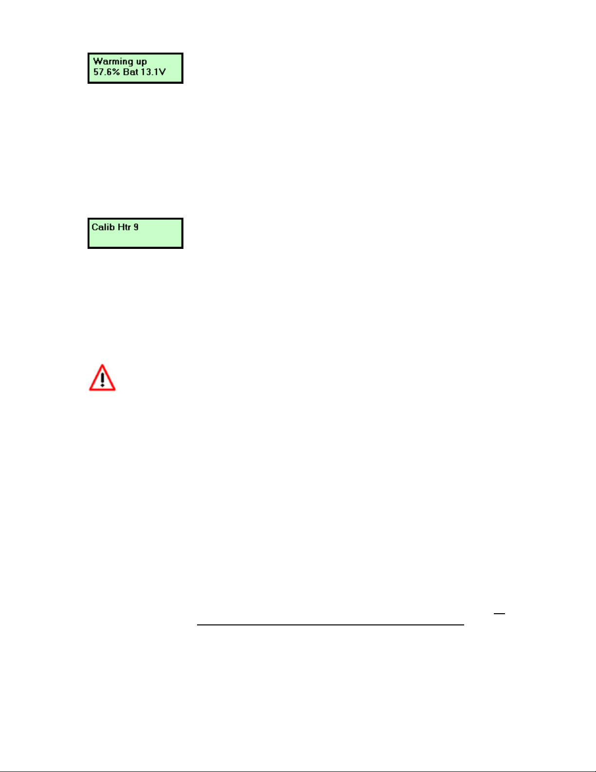
7. Switch the meter on. The display should show now:
- 4 -
Indicating that the sensor is warming up to its optimum operating temperature. The display shows
what percentage of the temperature is reached and what the battery voltage is that the meter
sees on the power connector. The warm-up period will last for about 30 seconds for a cold
sensor, depending on the sensor type used.
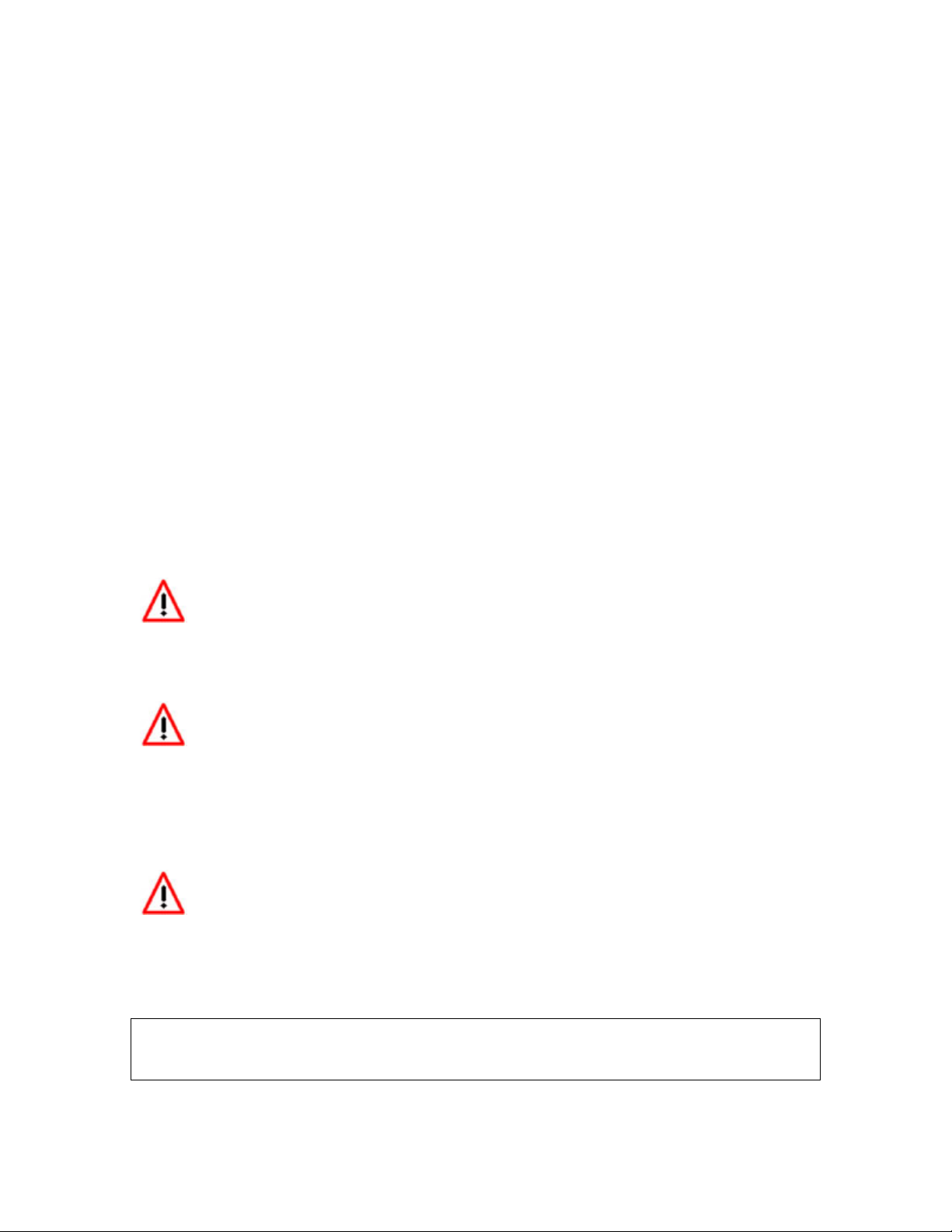
After the sensor is warmed up the meter automatically calibrates the sensor heater controller to
the particular sensor. During this 20-second period the LM-1 collects and calculates sensor
specific data required to quickly reach operating temperature in the future. After the first time use
the meter will use these values to regulate the sensor's temperature. During the heater calibration
the display will show:
Counting down to 0.
Note: When using the Bosch Sensors the LM-1 may perform multiple calibration passes. This is
normal and need not cause concern. When it completes, continue to step 8.
8. Press the Calibration button.
The meter will now calibrate itself by using air as a reference gas with known oxygen content.
After the calibration period is over (2-3 seconds), the instrument is ready to operate.
To recalibrate you need to hold down the Calibration button for a minimum of 2
seconds.
3. Installation
3.1. Mounting the sensor using a Bung or Exhaust Clamp.
Using a bung is the preferred method for mounting the O
2
sensor for both catalytic and
non-catalytic cars.
On
CATALYTIC CONVERTER equipped vehicles:
Bung: Install the oxygen sensor’s bung upstream from the catalytic converter
(a bung and plug is included in the LM-1 kit). Any decent muffler or
exhaust shop can do this for you. The wide-band oxygen sensor is then
installed into the bung to take a reading. (Insert the plug into the bung
when not in use). The bung must be installed in the exhaust pipe at
the side or on top, NOT on the bottom of the exhaust pipe. Best
position is between 10:00 and 2:00 position.
……or………
Exhaust Clamp: You may use the optional Exhaust Clamp to mount the O
2
sensor to the
car’s tail pipe when taking readings from cars with catalytic converters
(see below). However, it is recommended instead to use the bung (as
described above) to give you the most accurate reading. Measuring
after the cat will result in leaner-than-reality readings, depending on the
- 5 -
efficiency of the cat. Some operators of chassis dynos use this method
and roughly “correct” the reading.
On
NON-CATALYTIC converter vehicles:
Exhaust Clamp: With non-cat cars, you can simply take the reading from the car’s tail
pipe; however, you MUST use the optional Exhaust Clamp to do so. Do
NOT simply insert the O
2
sensor into the tail pipe. Doing so may
damage the sensor and it will certainly not yield accurate
measurements. (The oxygen sensor needs to have its cable exposed
to outside air to yield the most accurate results.)
……or………
Bung: You have the option with non-catalytic cars to also use a Bung as
described above. Use of a bung is the preferred method for mounting
the 0
2
sensor for both catalytic and non-catalytic cars.
On
TURBO CHARGED vehicles:
Bung: Install the bung downstream from the turbo before the catalytic
converter. The high exhaust pressure before the turbo interferes with
the lambda measurement and the high exhaust temperatures
encountered there can damage the sensor.
Do NOT install the Bung below the 3 o'clock or 9 o'clock position.
Condensation can form in the exhaust pipe and permanently damage the sensor.
6 o’clock is the absolute worst position to mount the sensor.
Wide band oxygen sensors – like the one shipped with the LM-1 – are
designed to work with unleaded gasoline. Using them with leaded gasoline will
significantly reduce the lifespan of the sensor. The reduction is directly
proportional to the metal content of the fuel. In most cases, a wide band sensor
will provide accurate measurements somewhere between 50 hours and 500 hours
with leaded fuel.
WHEN INSTALLED IN THE EXHAUST, THE OXYGEN SENSOR
MUST BE CONNECTED AND OPERATING WITH THE LM-1
WHENEVER THE CAR IS RUNNING. AN UN-POWERED OXYGEN
SENSOR WILL BE DAMAGED WHEN EXPOSED TO EXHAUST GAS.
RULE OF THUMB: POWER UP THE OXYGEN SENSOR
IMMEDIATELY AFTER THE ENGINE IS STARTED.
- 6 -
The maximum temperature of the sensor at the bung (the sensor hexagon)
should not exceed 500
o
C or 900
o
F. If these temperatures are exceeded in your
application you should either install a copper heat sink (instructions below) or the
Innovate Motorsports Heat-Sink Bung extender (HBX-1).
The bung extender is recommended for situations where airflow is restricted or
the encountered heat is higher than a heat sink can handle.
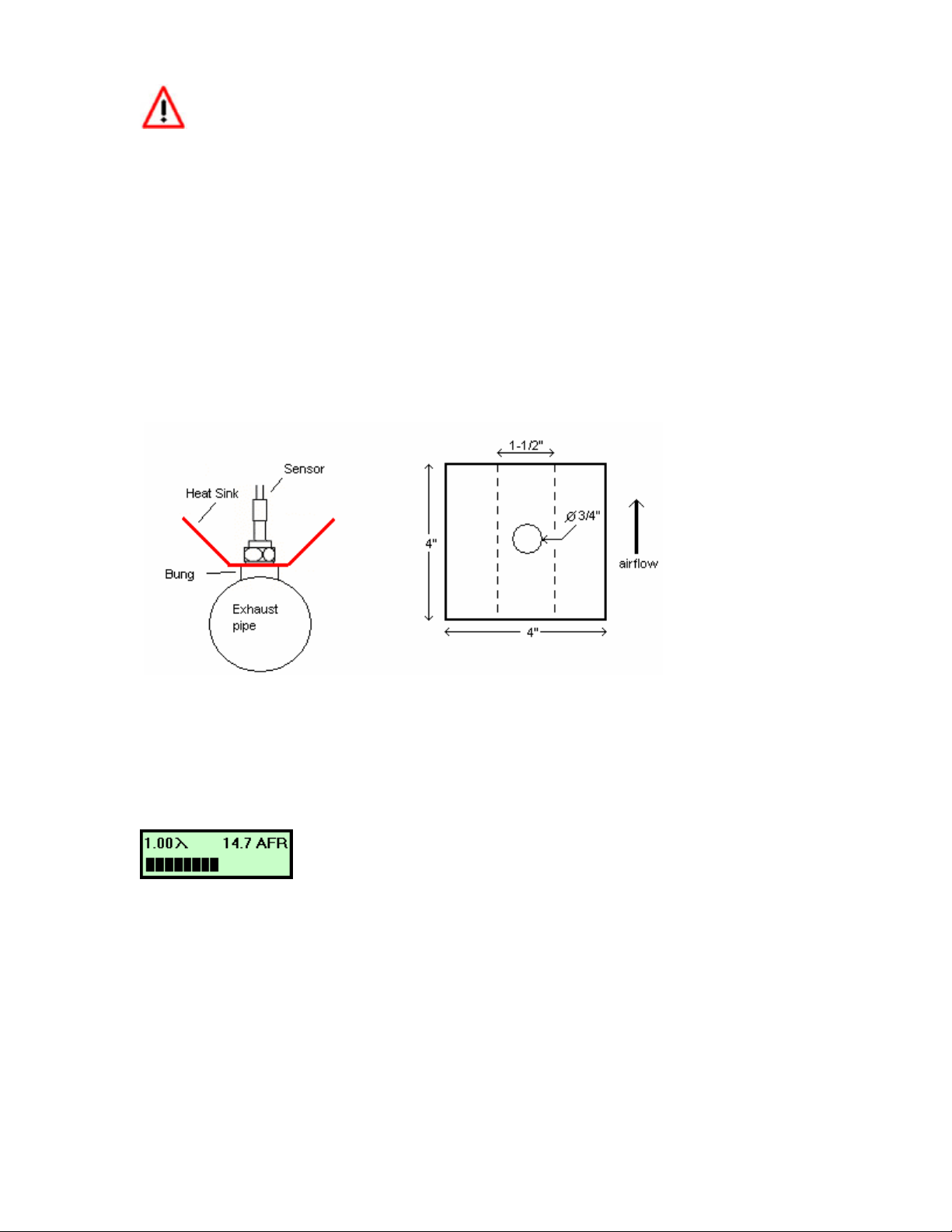
3.2. How to fabricate a copper heat sink
Use a 4” x 4” (10cm x 10 cm) sheet of copper sheet metal 14ga (1.5mm) thick. Drill a hole in the
center with the same diameter of the oxygen sensor threads ~3/4” (19mm).
Fold the sides up 45 deg and mount it between the sensor and the bung like you would a big
washer. Orient it such that the sides are exposed to good airflow.
4. Operation
Once the LM-1 has been installed and is in place (see Chapter 4: Installation), lambda
measurements can now be taken.
In operation, the meter's display shows:
showing both the current lambda value and air-fuel-ratio. The numeric lambda and air-fuel-ratio
values are averaged over about 0.2-0.3 seconds so that the numbers are more consistent and
easy to read.
If lambda is greater than 6 (for example, in free air), the display will show “—“ for Lambda, and
instead of an AFR reading, the percent of oxygen will be shown..
The bar-graph at the bottom shows the actual instant lambda value in 16 steps. The more of the
bar showing, the richer the mixture. The bar at mid-level means a lambda value of 1.0 (AFR of
14.7 for gasoline engines). If the whole bar shows, the actual lambda value is 0.68 or richer (AFR
of 10 or less for gasoline engines). If none of the bar shows the lambda value is 1.32 or leaner
(AFR 19.4 or more for gasoline engines).

- 7 -
5. Calibration
There are two types of calibration for the LM-1: free air calibration and sensor heater calibration.
Sensor heater calibration is automatically performed the first time a new sensor is used, while
free air calibration should be executed frequently.
5.1. Free air calibration
To achieve maximum precision, the LM-1 and its sensor needs to be recalibrated frequently.
When the measured lambda is greater than 6, the display will show the oxygen content in %. For
free air it should show 20.9%. If the display value is different by more than 0.6%, recalibrate. You
can test the oxygen sensor by breathing on it. The oxygen content of your breath will show.
The sensor MUST be operated in free air for calibration.
If the wide-band sensor is installed in a vehicle, wait 6-8 hours after running the engine so that all
exhaust gas is dissipated from the exhaust tract of the vehicle. Better yet, disengage the oxygen
sensor and expose the sensor to air (away from the exhaust) for calibration purposes:
1. Connect the meter to 12V from the vehicle and switch it on.
2. After the sensor has warmed up, press the 'Calibrate' button for a minimum of 2 seconds.
3. After the calibration is complete, switch the LM-1 off and wait for 30 seconds before you start
the car.
The display will show "Free Air Calibr." while it calibrates itself. When the calibration procedure is
finished (2-3 seconds), the display returns to normal showing lambda and oxygen content. If the
oxygen content now differs from 20.9% by more than 0.6%, repeat the calibration.
5.2. Sensor heater calibration
If you change the sensor – either with a replacement sensor or a new type of sensor --, the
heater circuit of the LM-1 needs to be recalibrated as well. (See steps in chapter 3 'First Time
Use'). The heater calibration data in the LM-1 will be reset when the meter is operated from 12V
without a sensor connected for at least 5 seconds. You can force a reset by doing this, and then
recalibrate by turning the unit off, reconnecting the sensor, and turning the unit on.
After the sensor is warmed up the meter automatically calibrates the sensor heater controller to
the particular sensor. During this 20-second period the LM-1 collects and calculates sensor-
specific data required to quickly reach operating temperature in the future. During the heater
calibration the display will show:
Counting down to 0.
Note: When using the Bosch Sensors the LM-1 may perform multiple calibration passes. This is
normal and need not cause concern. When it completes, continue to a free air calibration. It is
recommended to perform a free air calibration after any time the sensor heater is
recalibrated.
5.3. Calibration Schedule

- 8 -
Normally aspirated daily driver:
- Calibrate before installation of new sensor
- Calibrate new sensor again after 3 month of use
- Thereafter calibrate once a year or every 20,000 miles, whichever comes first
Turbo car, daily driver (tuned rich):
- Calibrate before installation of new sensor
- Calibrate new sensor again after 3 month of use
- Thereafter calibrate twice a year or every 10,000 miles, whichever comes first
Race car
- Calibrate before first installation of new sensor
- Calibrate once per race weekend
Dyno use
- Calibrate a new sensor
- Calibrate every 2-3 days, depending on usage
6. Recording other vehicle data with the LM-1
6.1. Overview
The LM-1 has the capability to record other vehicle data from other vehicle sensors while driving
so as to compile a complete log of engine data. For example, the optional LMA-2 cable provides
input for up to 5 other sensors (RPM plus 4 others) to the LM-1 whose data values will be
recorded.
Never connect the Aux inputs to 12 volt or battery power. Connecting the
inputs to sources that generate greater than 5 volts will result in damage to the
LM-1.
The LM-1 simply records the voltage on each input connection with a resolution of 10 bits (a
precision of 0.00488 Volt). LM-1 will record up to 44 minutes of data from all sensors including
lambda. A new value for each sensor is recorded every 0.08192 seconds (roughly 12
times/second). Software to view and analyze recorded data log files is included with your LM-1
and can also be downloaded at www.tuneyourengine.com.
6.2. Recording
To record data in the LM-1, press the 'Record' button. The LM-1 will display a blinking 'R'
between the lambda and AFR/O2 measurements while recording. To stop recording, press the
'Record' button again. Each time you start recording a new record ‘Session’ is created. A total of
44 minutes of data can be recorded in the LM-1. If the internal memory of the LM-1 is full, the
blinking 'R' will not show when starting a recording session. Instead it will show an 'F' for 'Full' for
a few seconds. To erase all recorded data, press and hold the 'Record' until 'RS' (for ReSet)
shows between lambda and AFR/O2 display.
Use the included LogWorks software package to download recorded data.
To erase all recorded data, press and hold the 'Record' until 'RS' (for ReSet)
shows between lambda and AFR/O2 display.
 Loading...