


LC-1 Digital Air/Fuel Ratio (Lambda)
Sensor Controller Manual
 Warning!
The Oxygen Sensor used in this device gets very hot in operation. Do not touch the hot sensor. Do not let a hot sensor touch a combustible surface. Do not use the sensor with or near flammable liquids or gases. Failure to heed these warnings may result in severe burns, explosions or fires.
When installed in the exhaust, the oxygen sensor MUST be connected and operating with the LC-1 whenever the car is running. An un-powered oxygen sensor will be quickly damaged when exposed to hot exhaust gases.
Document # 11-0053 11-0053 LC-1_Manual_1.9.doc
1 |
Overview................................................................................................................................... |
3 |
||
2 Mounting and Wiring the LC-1 ................................................................................................. |
4 |
|||
|
2.1 |
Indicator LED and Calibration button hookup: .................................................................. |
5 |
|
|
2.2 |
Connecting the LC-1 to an ECU or data logger................................................................ |
6 |
|
|
2.3 |
Electrical Grounding Concerns ..................................................................................... |
6 |
|
|
2.4 |
Mounting the sensor using a Bung. .................................................................................. |
6 |
|
|
2.5 |
How to fabricate a copper heat sink ................................................................................. |
8 |
|
3 |
First Time Use......................................................................................................................... |
8 |
||
4 |
Calibration ................................................................................................................................ |
9 |
||
|
4.1 |
Free air calibration.......................................................................................................... |
9 |
|
|
4.2 |
Sensor heater calibration............................................................................................... |
9 |
|
|
4.3 |
Calibration Schedule .................................................................................................... |
10 |
|
5 Remote display and recording of Lambda and/or AFR.......................................................... |
10 |
|||
|
5.1 |
Analog Lambda/AFR instrument..................................................................................... |
10 |
|
|
5.2 |
Digital XD-16 Instrument................................................................................................. |
11 |
|
|
5.3 |
Laptop recording of AFR or Lambda .............................................................................. |
11 |
|
|
5.4 |
Multi channel AFR recording with multiple LC-1’s and/or LM-1...................................... |
11 |
|
6 |
Programming the LC-1........................................................................................................... |
12 |
||
|
6.1 |
Installing the LM Programmer Software ......................................................................... |
12 |
|
|
6.2 |
Hooking up the LC-1 device to the computer ................................................................. |
12 |
|
|
6.3 |
Resetting the calibration data ......................................................................................... |
13 |
|
|
6.4 |
Updating the Firmware.................................................................................................... |
13 |
|
|
6.5 |
Programming the analog outputs.................................................................................... |
14 |
|
|
6.5.1 |
Advanced output programming................................................................................ |
14 |
|
7 Tips, Tricks and Troubleshooting ........................................................................................... |
16 |
|||
|
7.1 |
General measurement requirements .............................................................................. |
16 |
|
|
7.2 |
Vehicles with ‘smog-pumps’............................................................................................ |
16 |
|
|
7.3 |
Measuring at the tail-pipe................................................................................................ |
16 |
|
|
7.4 |
Single Cylinder Engines.................................................................................................. |
16 |
|
|
7.5 |
Diesel Engines ................................................................................................................ |
16 |
|
|
7.6 |
Reference cell or Pump cell circuit open or shorted errors............................................. |
16 |
|
|
7.7 |
Sensor Timing Errors ...................................................................................................... |
17 |
|
|
7.8 |
Analog Output tricks/hints ............................................................................................... |
17 |
|
8 |
Advanced Topics.................................................................................................................... |
17 |
||
|
8.1 |
Connecting the LC-1 to simulate a narrow band oxygen sensor.................................... |
17 |
|
Appendix A: LC-1 Cable Pinouts.................................................................................................. |
19 |
|||
Appendix B: LED blinking codes .................................................................................................. |
20 |
|||
Appendix C: LC-1 Error Codes and Troubleshooting Tips........................................................... |
21 |
|||
Appendix D: Limited Warranty...................................................................................................... |
22 |
|||
Appendix E: Kit Contents.............................................................................................................. |
23 |
|||
Revision History............................................................................................................................. |
24 |
|||
- 2 -
1 Overview
The LC-1 is a stand-alone Wideband Controller used to measure the Air/Fuel Ratio (AFR) or Lambda for an engine. For gasoline-driven engines, the theoretically optimal air fuel ratio is 14.7 pounds of air for every pound of fuel. At this ratio, theoretically, all available oxygen in the air combines with all available fuel. This ratio is called the stoichiometric ratio. Stoichiometric for different fuels are as follows:
Gasoline |
14.7 |
LPG (Propane) 15.5 |
|
Methanol |
6.4 |
Ethanol |
9.0 |
CNG |
17.2 |
Diesel |
14.6 |
The measurement Lambda is the actual air fuel ratio over the stoichiometric ratio. A Lambda measurement of “1” equates to the air fuel ratio of 14.7 (for gasoline engines). When Lambda is less than 1 the engine runs “rich”, i.e., unburned fuel exists in the exhaust stream. If lambda is greater than 1 the engine runs lean, i.e., free oxygen (02) is present in the exhaust. Depending on the engine, maximum power is typically delivered when the engine runs slightly rich (for example at lambda values of 0.8 to 0.9 for most engines). This instrument provides a means to measure the actual air fuel ratio or lambda in the engine in operation directly from the exhaust. For this a special wide-band oxygen sensor is used to measure the lambda value derived from the oxygen content (or lack thereof) of the exhaust gases.
- 3 -
2Mounting and Wiring the LC-1
1.Find a suitable location under your vehicle where the LC-1 body can be mounted. Using zip ties or other suitable method, fasten the body of the LC-1 device securely to the framerails or other mounting points as far away from the heat of the exhaust system as the sensor cable allows. DO NOT zip-tie the LC-1 by the cables.
2.Route the cables from the LC-1 (except sensor cable) into the car interior under the dash.
3.LC-1 Cable connections:
A. Interface and power cables with 6 stripped ends*:
a. Red |
12V supply |
b. Blue |
Heater Ground |
c. White |
System Ground |
d. Yellow |
Analog out 1 |
e. Brown |
Analog out 2 |
f. Black |
Calibration wire |
B.Serial In connection, 2.5mm stereo (female) marked as IN
C.Serial Out connection, 2.5 mm stereo (female) marked as OUT.
*3.1 If you have an LC-1 with only 7 stripped ends the wiring is as follows:
a. Red |
12V supply |
b. Blue |
Heater Ground |
c. White |
System Ground |
d. Yellow |
Analog out 1 |
e. Brown |
Analog out 2 |
f. Green |
Analog Ground |
g. Black |
Calibration wire |
4.Connect the RED wire to a switched 12V source in your car. A switched 12V source goes on as soon as the ignition on the car is on. Make sure the connection is fused with a minimum fuse size of 5A.
5.The BLUE and WHITE wires should all be grounded to the same ground source. Optimally, these (and any other MTS device ground) will be soldered to the same lug, and connected to a single point. When this isn’t possible, connect each one to a separate lug, and attach in close proximity. Multiple lugs on the same bolt is not optimal, and can result in unwanted signal “noise.” When possible, soldering is always better than crimping. Please see chapter 2.3 for more information on Electrical Grounding Concerns.
6.Optionally, the YELLOW (Analog out 1) and/or BROWN (Analog out 2) can be connected to the analog inputs of other devices such as data loggers, ECUs, or gauges. If either one or both of these wires are not being used isolate and tape the wire(s) out of the way. The default analog outputs are as follows: Analog output one is 1.1V = 14 AFR and .1V = 15 AFR. This is a simulated narrowband signal. Analog output two is setup as 0V = 7.35 AFR and 5V = 22.39 AFR. Note: The LC-1’s heater ground and system ground wires should share the same grounding location of the analog input’s ground. Refer to chapter 2.2 for recommended wiring schematics.
7.Optionally connect a momentary push-button switch between ground and the BLACK calibration wire. Please refer to section 2.1.
Note: The use of the calibration wire is not necessary if the LC-1 is connected to Innovate Motorsports’ XD-16 digital gauge. If the wire is not are not being used, isolate and tape the wire out of the way.
-4 -

8. Optionally connect a indication LED (1.2-2.2V, 1-30mA is recommended) between the calibration wire and ground. Please refer to section 2.1
2.1Indicator LED and Calibration button hookup:
The LED will communicate the LC-1’s status. To monitor LC-1 status, connect the red wire (Anode) of the included LED to the calibration wire (black) of the LC-1 and connect the black wire (Cathode) of the LED to the ground wire of the momentary switch. The grounds to both the cathode side of the LED and the Push button should be connected with the Heater ground.
a.Note: The included LED will fit the following hole size and panel thickness: a 5/32” (0.155” - 0.158”) hole size and a panel thickness of 28–16gauge (0.031” - 0.062”).
b.Optionally, any 1.2V - 2.2V (1mA30mA) LED may be used. A typical LED has 2 wires called Anode and Cathode. The Cathode side is typically the shorter of the 2 wires or the black wire.
Pressing the push-button or connecting the black wire to ground (a three second press is required with firmware version 1.10) starts a free air calibration process in the LC-1. MAKE SURE THE SENSOR IS IN FREE AIR FOR THAT. See chapter 4 for details.
See Appendix B for LED status codes.
- 5 -

2.2Connecting the LC-1 to an ECU or data logger
All Innovate MTS devices like the LC-1 with dual serial ports should have their system grounds connected together to a common ground point. If an external data logger or ECU is to be fed by an MTS device, the MTS ground should be located at or near the ECU or data logger’s input signal ground. Some ECU’s or data loggers have differential inputs. A differential input has a separate ground INPUT for each sensor input. This ground input MUST be connected also to ground as shown in these diagrams. If one analog output of the LC-1 is used to drive an AFR display and the other output is used to connect to an ECU, the AFR display ground should be connected to the ECU ground. The schematics below can also adapted for 7-wire LC-1s.
Simply wire the Green analog ground wire with the System ground.
2.3Electrical Grounding Concerns
The electrical environment inside a car provides unique challenges, combining high voltages and currents, low-voltage signals, convoluted signal paths, and variable conditions (i.e., fans turning on and off, or starter cranking).
When using precision electronics, it is important for ALL electronics to share a common ground. Remember that “Ground” is more than just the return path for any circuitit is also the reference against which any voltage is measured.
Since it is not always practical to ground every device to the exact same location, here are some tips on grounding:
1.The BEST grounding scheme is all grounds (i.e., ECU, Gauges, LC1 heater, LC1 system, etc.) SOLDERED into a single lug and bolted to the engine block.
2.The next best is all grounds attached to the same source, as close as possible, but on separate lugs. This is because even the corrosion between lugs can create ground offset and noise. Incidentally, this is why many ECUs have separate ground wires for injectors vs. ECU system groundseparating high voltages and low voltages reduces noise.
3.Grounding to the engine block is usually better than grounding to the frame.
4.Grounding a gauge to the radio is usually badground offset can vary with volume.
5.Grounding to an ECU housing is generally not optimalhousings are strapped to the frame for shielding, but not necessarily grounded.
6.One of the WORST things to do is to ground most of your electronics to one place (i.e. the engine block), but ground one device somewhere else (i.e., the frame). Not only can this result in ground offsets, it can also create a “path of least resistance” for high currents THROUGH a low-current device. This can result in melted wires and vaporized diodes, when, for example, starter currents flow through gauges.
2.4Mounting the sensor using a Bung.
- 6 -
Using a bung is the preferred method for mounting the O2 sensor for both catalytic and non-catalytic cars.
On CATALYTIC CONVERTER equipped vehicles:
Install the oxygen sensor’s bung upstream from the catalytic converter (a bung and plug is included in the LC-1 kit). Any decent muffler or exhaust shop can do this for you. The wideband oxygen sensor is then installed into the bung to take a reading. (Insert the plug into the bung when not in use). The bung must be installed in the exhaust pipe at the side or on top, NOT on the bottom of the exhaust pipe. Best position is between 10:00 and 2:00 position.
On NON-CATALYTIC converter vehicles:
You have the option with non-catalytic cars to also use a Bung as described above. Use of a bung is the preferred method for mounting the 02 sensor for both catalytic and non-catalytic cars.
On TURBO CHARGED vehicles:
Install the bung downstream from the turbo before the catalytic converter. The high exhaust pressure before the turbo interferes with the lambda measurement and the high exhaust temperatures encountered there can damage the sensor.
 Do NOT install the Bung below the 3 o'clock or 9 o'clock position. Condensation can form in the exhaust pipe and permanently damage the sensor. 6 o’clock is the absolute worst position to mount the sensor.
 Wide band oxygen sensors – like the one shipped optionally with the LC-1
– are designed to work with unleaded gasoline. Using them with leaded gasoline will significantly reduce the lifespan of the sensor. The reduction is directly proportional to the metal content of the fuel. In most cases, a wide band sensor will provide accurate measurements somewhere between 50 hours and 500 hours with leaded fuel.
 WHEN INSTALLED IN THE EXHAUST, THE OXYGEN SENSOR MUST BE CONNECTED AND OPERATING WITH THE LC-1 WHENEVER THE CAR IS RUNNING. AN UN-POWERED OXYGEN SENSOR WILL BE DAMAGED WHEN EXPOSED TO EXHAUST GAS.
- 7 -
 The maximum temperature of the sensor at the bung (the sensor hexagon) should not exceed 500 oC or 900 oF. If these temperatures are exceeded in your application you should either install a copper heat sink (instructions below) or the Innovate Motorsports Heat-Sink Bung extender (HBX-1).
The bung extender is recommended for situations where airflow is restricted or the encountered heat is higher than a heat sink can handle.
 It is NOT a good idea to connect the LC-1 permanently to 12V and switch it on with a separate switch before the vehicle is started. Depending on the climate and the sensor position in the exhaust, condensation water can form in the exhaust pipes. This condensation water could then be blown by the exhaust stream against the hot sensor when the car is started. The resulting heat shock can permanently damage the sensor.
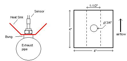
2.5How to fabricate a copper heat sink
Use a 4” x 4” (10cm x 10 cm) sheet of copper sheet metal 14ga (1.5mm) thick. Drill a hole in the center with the same diameter of the oxygen sensor threads ~3/4” (19mm).
Fold the sides up 45 deg and mount it between the sensor and the bung like you would a big washer. Orient it such that the sides are exposed to good airflow.
3 First Time Use
1.Do not connect the sensor yet.
2.Switch 12V supply to the LC-1 on and wait for 10 seconds.
3.Switch the 12V supply off after 10 seconds.
4.Connect the sensor to the sensor interface connector. The sensor must be exposed to air for the first time calibration.
-8 -
 Loading...