

Innovate Motorsports ST-12 User Manual

ST-12
SuperTune 12 Engine Data Acquisition System
Warning!
The Oxygen Sensor used in this device gets very hot in operation. Do not touch the hot sensor.
Do not let a hot sensor touch a combustible surface. Do not use the sensor with or near
flammable liquids or gases. Failure to heed these warnings may result in severe burns,
explosions or fires.
When installed in the exhaust, the oxygen sensor MUST be connected and operating with the ST-
12 whenever the car is running. An un-powered oxygen sensor will be quickly damaged when
exposed to hot exhaust gases.
ST12_Manual_1.1.doc

1 Overview...............................................................................................................................................................3
2 The SuperTune-12 (ST-12)...................................................................................................................................4
3 First Time Use.......................................................................................................................................................5
3.1 Launching and connecting LogWorks.............................................................................................. ............5
3.2 Connecting the LC-1ST to the ST-12 and Calibration .................................................................................6
3.3 Selecting internal sensors............................................................................................................................7
4 LC-1ST..................................................................................................................................................................8
4.1 Calibration....................................................................................................................................................8
4.2 Free air calibration........................................................................................................................................8
4.3 Sensor heater calibration .............................................................................................................................9
4.4 Sensor Location ...........................................................................................................................................9
4.5 HBX-1.........................................................................................................................................................11
4.6 Programming the LC-1ST..........................................................................................................................11
4.6.1 Resetting the calibration data ................................................................................................................12
4.6.2 Updating the Firmware...........................................................................................................................12
4.6.3 Programming the analog outputs...........................................................................................................12
4.6.4 Advanced output programming..............................................................................................................13
5 Internal Sensors..................................................................................................................................................14
5.1 Connecting Type K Thermocouples...........................................................................................................14
5.2 Connecting an RPM signal.........................................................................................................................15
5.2.1 Using the Variable Potentiometer..........................................................................................................15
5.2.2 RPM Measurement basics.....................................................................................................................15
5.2.3 Four-Stroke Engines..............................................................................................................................16
5.2.4 Two-Stroke Engines...............................................................................................................................16
5.2.5 Rotary Engines (Wankel Engine)...........................................................................................................16
5.2.6 How the ST-12 determines RPM...........................................................................................................16
5.2.7 Programming the RPM input..................................................................................................................17
5.2.8 Using the ST-12 with the Inductive Clamp.............................................................................................18
5.2.9 Inductive Clamp Usage..........................................................................................................................18
5.2.10 Using the RPM-Converter with pulsed RPM input (Tach) signals.....................................................19
5.3 Measuring Pressures .................................................................................................................................19
5.3.1 Measuring MAP .....................................................................................................................................19
5.3.2 Measuring boost/vacuum.......................................................................................................................19
5.4 Measuring Ignition Advance.......................................................................................................................20
5.4.1 Making your own optical reference pulse sensor ..................................................................................22
5.5 Measuring Frequencies, custom RPM, or speed.......................................................................................23
5.6 Measuring duty cycle..................................................................................................................................24
6 Programming the ST-12......................................................................................................................................24
6.1 Changing the device name ........................................................................................................................25
6.2 Updating the firmware................................................................................................................................25
6.3 Input 1 Configuration..................................................................................................................................25
6.3.1 Measuring RPM.....................................................................................................................................26
6.3.2 Measuring Frequency............................................................................................................................27
6.3.3 Measuring Speed...................................................................................................................................27
6.3.4 Duty cycle ..............................................................................................................................................28
6.4 Input 2 Configuration..................................................................................................................................28
6.5 Input 3 configuration...................................................................................................................................28
6.6 Input 4 configuration...................................................................................................................................29
6.7 Input 5 configuration...................................................................................................................................29
7 Appendix.............................................................................................................................................................30
7.1 Error Codes................................................................................................................................................30
7.2 LED Blinking Codes ...................................................................................................................................31
7.3 ST-12 Do’s and Don’ts...............................................................................................................................32
8 Revision History..................................................................................................................................................33
2

1 Overview
The SuperTune-12 is a complete data acquisition system for advanced engine tuning. The system is
capable of logging up to 12 Air/Fuel channels and also includes flexible sensors for RPM, MAP,
Temperature, Duty Cycle, and analog inputs.
The ST-12 can power, manage, and consolidate data from up to 12 specialized LC-1STs (Lambda
Cable) wideband oxygen sensor controller cables. The specialized cables are functionally identical to the
standard LC-1ST cables, except they are 18 ft. long, terminated with a single ST-12 (DB-15) connector,
and sleeved in a rugged thermal insulator.
The ST-12’s LC-1ST is a Wideband Controller used to measure the Air/Fuel Ratio (AFR) or Lambda for
an engine. For gasoline-driven engines, the theoretically optimal air fuel ratio is 14.7 pounds of air for
every pound of fuel. At this ratio, theoretically, all available oxygen in the air combines with all available
fuel. This ratio is called the stoichiometric ratio. Stoichiometric for different fuels are as follows:
Gasoline 14.7
LPG (Propane) 15.5
Methanol 6.4
Ethanol 9.0
CNG 17.2
Diesel 14.6
The measurement Lambda is the actual air fuel ratio over the stoichiometric ratio. A Lambda
measurement of “1” equates to the air fuel ratio of 14.7 (for gasoline engines). When Lambda is less
than 1 the engine runs “rich”, i.e., unburned fuel exists in the exhaust stream. If lambda is greater than 1
the engine runs lean, i.e., free oxygen (0
2
) is present in the exhaust. Depending on the engine, maximum
power is typically delivered when the engine runs slightly rich (for example at lambda values of 0.8 to 0.9
for most engines). This instrument provides a means to measure the actual air fuel ratio or lambda in the
engine in operation directly from the exhaust. For this a special wide-band oxygen sensor is used to
measure the lambda value derived from the oxygen content (or lack thereof) of the exhaust gases.
3
r
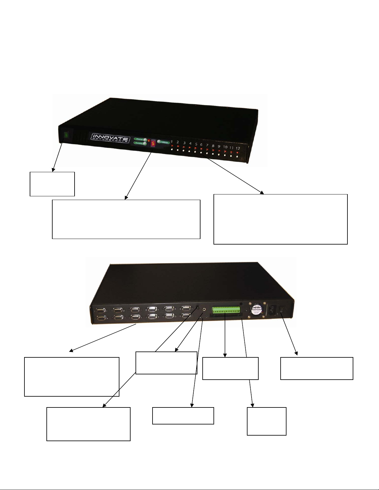
2 The SuperTune-12 (ST-12)
ON/OFF
switch
Program functions such as RPM, MAP,
Temperature, Duty Cycle, and analog inputs.
RPM calibration number can also be
Digital connection from
each individual LC-1ST
(wideband controller) to
the DB-15 connecto
programmed here.
Variable
Potentiometer to
adjust the RPM signal
LED indicates LC-1ST conditions
such as warming up, normal
operation, or error codes.
Push buttons trigger a Free Air
Calibration on the LC-1STs.
Inductive
Clamp input
Analog Inputs Power Supply
Serial In/Out Analog
Front
View
Rear View
On/Off switch
Outputs
4
3 First Time Use
Put the included CD in your CD-drive on your computer and follow the instructions on screen. The
Software will be installed including pre-set directories for log-data and downloaded software. The LM
Installer also puts entries for the LM Software in the Start-Menu of your computer under the heading
‘Innovate!’.
The following items will be installed on your hard-drive
1. LM Programmer
This is used to program the analog outputs of the LC-1ST, the fuel type used, the sensor type
used, and also allows to ‘reflash’ the firmware of the LC-1ST.
2. LogWorks
This is a comprehensive data logging and analysis package. It also allows real-time logging and
display.
3.1 Launching and connecting LogWorks
Connect the Serial OUT port of the ST-12 to a free serial port on your computer and start the LogWorks
program.
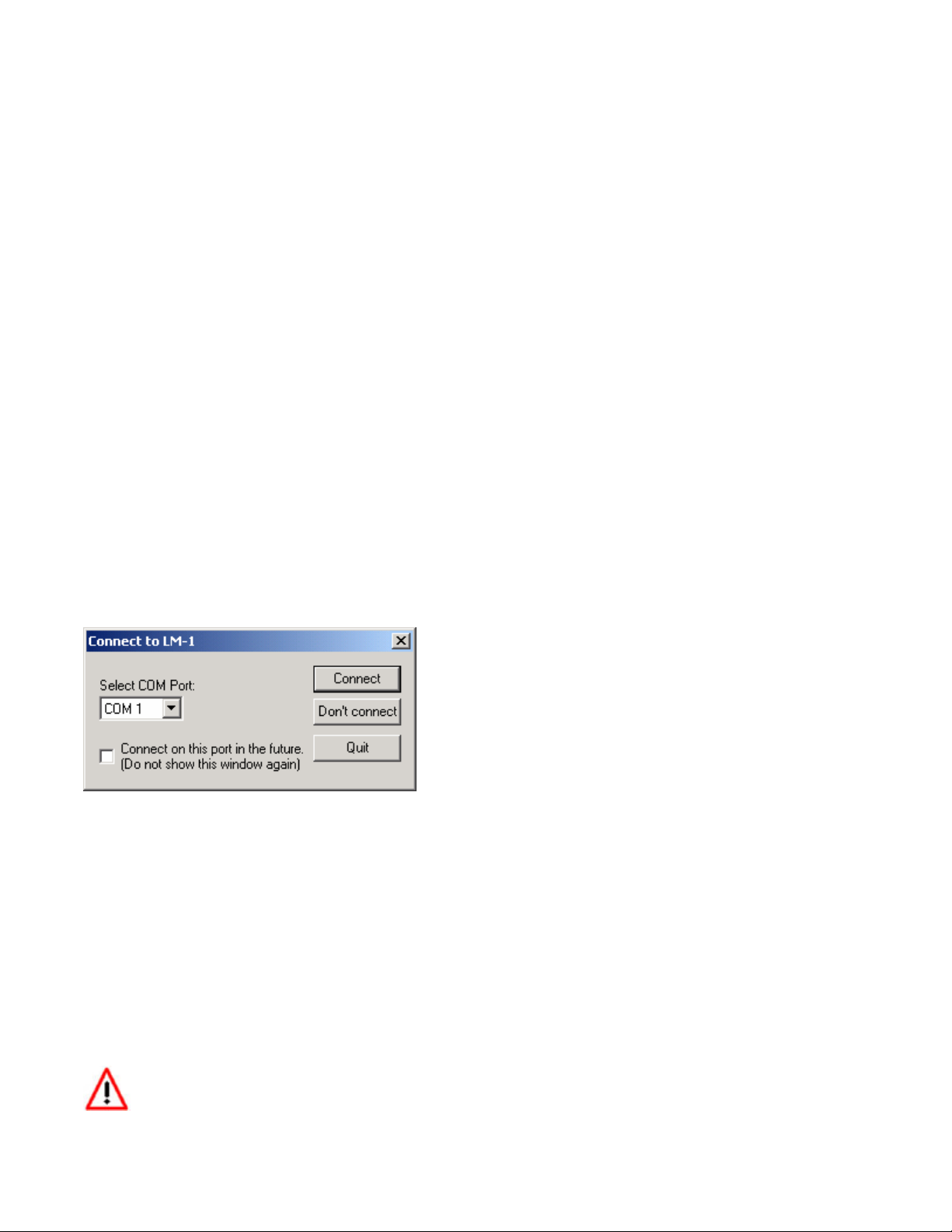
The following dialog box will appear:
Select the serial port (COM Port) to which the Log-Chain is connected. Then press the Connect button.
To quit here and don’t start LogWorks press the Quit button.
If you do not wish to connect to the chain of sensors (or don’t have it connected), Press the “Don’t
connect” button.
Check the “Connect on this port in the future” checkbox if you want to auto-connect on the selected port
always in the future (you can change that later on if you wish).
LogWorks can also be started by dragging one or more log files on the LogWorks icon (if you installed
one on the desktop). In this case the log files will be opened automatically.
Make sure no other program (including LM Programmer) is using the selected serial port.
5
3.2 Connecting the LC-1ST to the ST-12 and Calibration
Note: The calibration process can be done with multiple LC-1STs
at one time
Connect the DB-15 connector from the LC-1ST to the ST-12.
1 Do not connect the sensor to the LC-1ST yet.
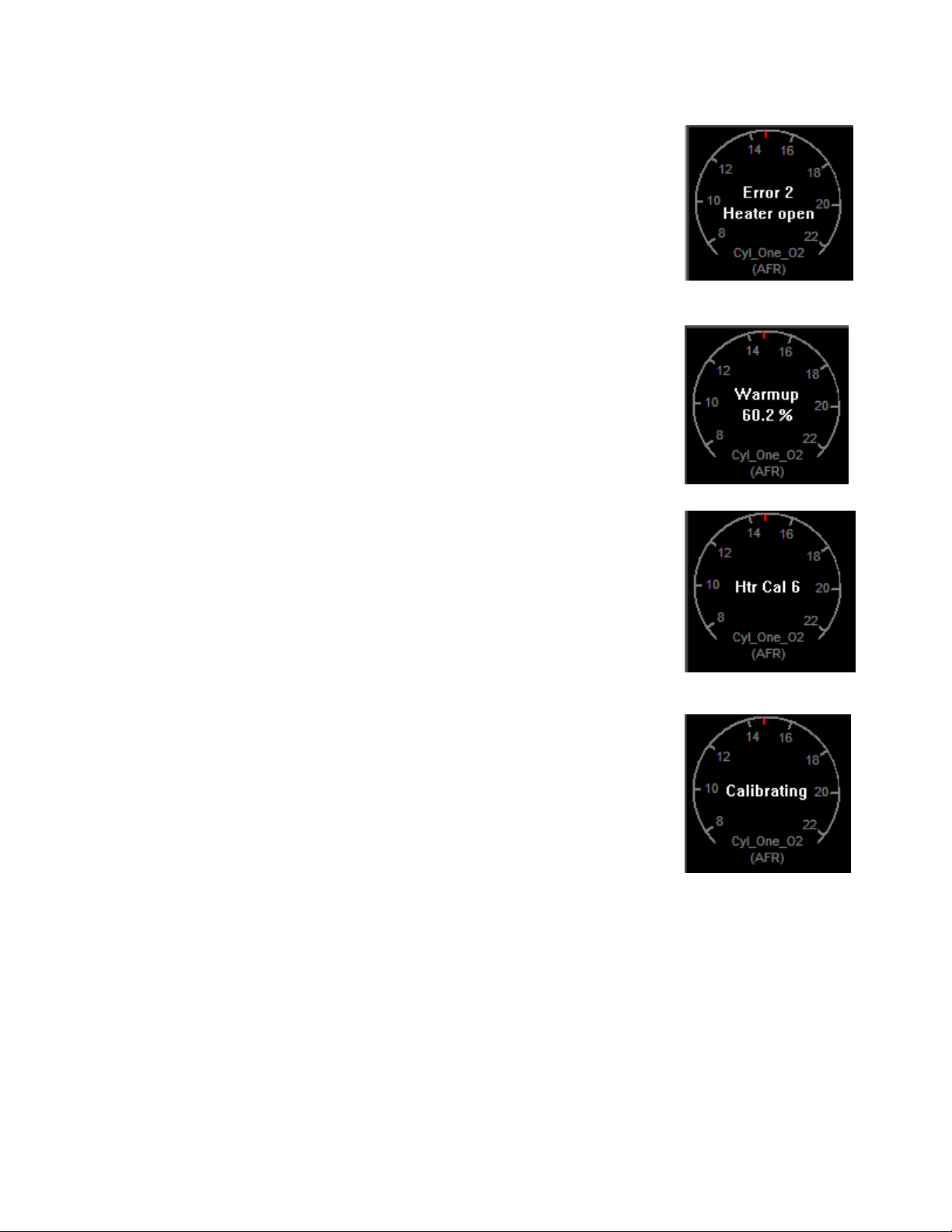
2 Switch ON the power supply on the ST-12. You should see the following
screen in LogWorks:
3 Switch off the power supply after 10 seconds.
4 Connect the sensor to the sensor interface connector on the LC-1ST. The
sensor must be exposed to free air (outside of the exhaust) for the
first time calibration.
5 Switch ON the power supply on the ST-12. After the sensor is warmed
up, the LC-1ST automatically calibrates the sensor heater controller to
the particular sensor. During this 20-second period the LC-1ST collects
and calculates sensor specific data required to quickly reach operating temperature in the future.
During the heater calibration the screen will show a “Htr Cal” count down
from 9 to 0.
6 Press the Calibration button for the LC-1ST
on the front of the ST-12. The
LC-1ST will now calibrate itself by using air as a reference gas with
known oxygen content. After the calibration period is over (2-3 seconds),
the instrument is ready to operate.
In general, it’s only necessary to calibrate the sensor heater the first time you
use a new sensor, while the free air calibration is required more frequently.
Free air calibration will correct for: 1) A change in atmospheric pressure (i.e.
going from sea level to 6,000 ft. above for a race); or 2) Sensor wear (i.e.
regular use for hundreds of hours).
Heater calibration detects and stores the impedance characteristics of a new sensor. Generally these
characteristics don’t change with wear, however some forms of carbonization can impact the impedance
of the sensor. The most common problematic carbonization comes from the use of leaded gas. If you see
an error #4 (Pump cell circuit open) after using the sensor with leaded gas, you probably need to perform
a heater recalibration. If you use sensor regularly with race gas, we recommend keeping a backup
sensor, and performing heater recalibrations more frequently.
6
The Heater Calibration and Free Air Calibration are unique to each sensor. If you use a
different sensor on a LC-1ST you will need to run through the whole Calibration procedure again
(section 3.2)!
3.3 Selecting internal sensors.
Table 1:
Input
Functio
ns
Input 1 Functions
Function
Indicator
Functionality RPM
Input 2 Functions
Function
Indicator
Functionality Thermocouple
Input 3 Functions
Function
Indicator
Functionality Duty Cycle Ignition
1 2 F d =
RPM
(0..10230)
1 2 =
EGT range
(0..1093
degC,
32..1999
degF)
1 2 F =
(0..20460)
Thermocouple
CHT range
(0..300 degC,
32..572 degF)
Timing
Frequency
(straight
frequency,
Speed
sensor,
Custom
RPM range
External
0..5V
sensors
Frequency
(straight
frequency,
Speed
sensor,
Custom
RPM range
Duty Cycle External
0..5V
sensors
External
0..5V
sensors
7

Input 4 Functions
Function
Indicator
Functionality MAP (1
Input 5 Functions
Function
Indicator
Functionality Frequency
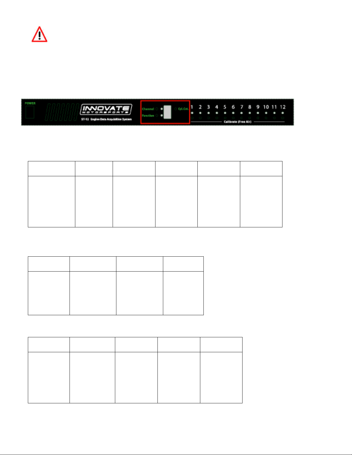
To program an input channel, repeatedly press the ‘Channel’ button until the channel number to program
appears on the ST-12 digit display. Then repeatedly press the ‘Function’ button until the digit display
shows the intended function. The digit display will switch rapidly between indicating the input channel
number and the set function. The LEDs next to the channel and function buttons will indicate which value
is being displayed.
If the function selected is External input, the digit display shows a ‘=’.
1 2 3 4 F d =
MAP (3
bar)
(0..101.3
kPa)
F d =
(straight
frequency,
Speed
sensor,
Custom
RPM
range
bar)
(0..304.1
kPa)
Duty
Cycle
Vacuum
(0..30
inHg
Vacc)
External
0..5V
sensors
Vacuum/Boost
(-14.7PSI…
29.4 PSI)
Frequency
(straight
frequency,
Speed
sensor,
Custom
RPM
range
Duty
Cycle
External
0..5V
sensors
4 LC-1ST
4.1 Calibration
There are two types of calibration for the LC-1ST: free air calibration and sensor heater calibration.
Sensor heater calibration is automatically performed the first time a new sensor is used and the free air
calibration can be triggered from the “calibrate” button in from of the ST-12.
4.2 Free air calibration
To achieve maximum precision, the LC-1ST and its sensor needs to be recalibrated frequently with the
sensor outside of the exhaust.
8

The sensor MUST be operated in free air for calibration.
Remove the oxygen sensor and expose the sensor to air (away from the exhaust) for calibration
purposes:
1 Connect the LC-1ST to the ST-12 and switch it on.
2 After the sensor has warmed up, press the pushbutton.
If a LED indicator on the face of the ST-12 will be off during the free air calibration.
4.3 Sensor heater calibration
If you change the sensor – either with a replacement sensor or a new type of sensor --, the heater circuit
of the LC-1ST needs to be recalibrated as well. (See steps in chapter 3 'First Time Use'). The heater
calibration data in the LC-1ST will be reset when the device is operated from ST-12 without a sensor
connected for at least 5 seconds. You can force a reset by doing this, and then recalibrate by turning the
unit off, reconnecting the sensor, and turning the ST-12 on.
After the sensor is warmed up the ST-12 automatically calibrates the sensor heater controller to the
particular sensor. During this 20-second period the LC-1ST collects and calculates sensor-specific data
required to quickly reach operating temperature in the future.
Note: When using the Bosch Sensors the LC-1ST may perform multiple calibration passes. This is
normal and need not cause concern. When it completes, the LC-1ST also will perform a free air
calibration. Make sure the sensor is operating in free air for the heater and free air calibration.
4.4 Sensor Location
Using a bung is the preferred method for mounting the O
2
sensor for both catalytic and non-
catalytic cars.
On
CATALYTIC CONVERTER equipped vehicles:
Install the oxygen sensor’s bung upstream from the catalytic converter (a bung and plug is included in
the LC-1ST kit). Any decent muffler or exhaust shop can do this for you. The wide-band oxygen
sensor is then installed into the bung to take a reading. (Insert the plug into the bung when not in
use). The bung must be installed in the exhaust pipe at the side or on top, NOT on the bottom
of the exhaust pipe
. Best position is between 10:00 and 2:00 position.
On
NON-CATALYTIC converter vehicles:
You have the option with non-catalytic cars to also use a Bung as described above. Use of a bung is
the preferred method for mounting the 0
2
sensor for both catalytic and non-catalytic cars.
On
TURBO CHARGED vehicles:
9

Install the bung downstream from the turbo before the catalytic converter. The high exhaust pressure
before the turbo interferes with the lambda measurement and the high exhaust temperatures
encountered there can damage the sensor.
Sensor placement before the turbo is not recommend because of negative effects caused
by back pressure and high temperatures.
Do NOT install the Bung below the 3 o'clock or 9 o'clock position. Condensation can form
in the exhaust pipe and permanently damage the sensor. 6 o’clock is the absolute worst position
to mount the sensor.
Wide band oxygen sensors – like the one shipped optionally with the LC-1ST – are
designed to work with unleaded gasoline. Using them with leaded gasoline will significantly
reduce the lifespan of the sensor. The reduction is directly proportional to the metal content of
the fuel. In most cases, a wide band sensor will provide accurate measurements somewhere
between 50 hours and 500 hours with leaded fuel.
WHEN INSTALLED IN THE EXHAUST, THE OXYGEN SENSOR MUST BE CONNECTED AND
OPERATING WITH THE LC-1ST WHENEVER THE ENGINE IS RUNNING. AN UN-POWERED
OXYGEN SENSOR WILL BE DAMAGED WHEN EXPOSED TO EXHAUST GAS.
The maximum temperature of the sensor at the bung (the sensor hexagon) should not
exceed 500
o
C or 900 oF. If these temperatures are exceeded in your application install the
Innovate Motorsports’ Heat-Sink Bung extender (HBX-1).
The bung extender is recommended for situations where airflow is restricted or the encountered
heat is higher than a heat sink can handle.
Depending on the climate and the sensor position in the exhaust, condensation water can
form in the exhaust pipes. This condensation water could then be blown by the exhaust stream
against the hot sensor when the car is started. The resulting heat shock can permanently damage
the sensor.
10
 Loading...