

Innovate Motorsports OT-1 User Manual

OT-1 16 Channel OBD-II Interface
User Manual
OT1_Manual_1.0.doc

1.
Overview............................................................................................................................... 3
1.1 OBD-II ............................................................................................................................... 3
1.2 Why is CAN so special?.................................................................................................... 4
1.3 MTS and the Log Chain Concept...................................................................................... 5
1.4 MTS Advantages............................................................................................................... 6
2. Installing the OT-1 ................................................................................................................ 7
2.1 Confirm the Contents of your Kit....................................................................................... 7
2.2 Locate the OBD-II Connector in your vehicle ................................................................... 8
2.3 Connect the OT-1 to your vehicle’s OBD-II port...............................................................9
2.4 Turn on the ignition switch and establish an OBD-II connection...................................... 9
3. Configuring the OT-1.......................................................................................................... 10
3.1 Install the Innovate Software Suite from the included CD .............................................. 10
3.2 Connect a USB cable between the computer and the OT-1 .......................................... 10
3.3 Run LM Programmer ...................................................................................................... 11
3.4 Select OBD-II Protocol and number of MTS Channels .................................................. 11
3.5 Assign MTS Channels to OBD-II Inputs ......................................................................... 12
3.6 Set the Priority of OBD-II Inputs (Optional)..................................................................... 15
3.7 Check and Clear any Vehicle Trouble Codes (Optional)................................................ 19
4. Getting Started With LogWorks.......................................................................................... 20
4.1 Make sure LM Programmer is not running! .................................................................... 20
4.2 Starting LogWorks.......................................................................................................... 20
4.3 Select the COM port to Log from....................................................................................20
4.4 Configure the OT-1 Channels for the proper OBD-II value ............................................ 22
4.5 Creating your First Log ................................................................................................... 23
5. Connecting with other MTS Devices .................................................................................. 24
6. Specifications...................................................................................................................... 25
Appendix A: Limited Warranty...................................................................................................... 26
Appendix B: Supported PIDs........................................................................................................27
Revision History............................................................................................................................. 29
- 2 -

1. Overview
The Innovate Motorsports OT-1 allows you to read up to 16 channels of “OBD-II” (“On Board
Diagnostic) information directly from your vehicle’s engine control unit (ECU) and integrate it into
an Innovate MTS (“Modular Tuning System”) “Log Chain”. An MTS Log Chain can be logged
(recorded) and analyzed on a personal computer using Innovate’s award winning LogWorks
software (included with the OT-1) or other 3rd party MTS compatible applications.
MTS Log Chains can also be recorded using stand-alone MTS compatible data-loggers, like
Innovate’s DL-32 data-logger and LM-2 handheld lambda meter with built-in data-logging. And
data channels from an MTS Log Chain can be displayed on MTS compatible gauges such as
Innovate’s XD-16 or on MTS compatible 3rd party multi-function in-vehicle displays (see
www.tuneyourengine.com
If you are the sort of person who already knows that “DTC” stands for Diagnostic Trouble Code
and does not flinch at the words “my ’01 Suburban has been throwing P1336 since I replaced the
CAS…” please feel free to move on to Chapter 2, “Installing the OT-1”. The remainder of this
chapter will be an introduction to some basic OBD-II and MTS concepts.
1.1 OBD-II
Again, OBD stands for “On Board Diagnostics”. It represents a collection of industry and
legislative standards for getting basic diagnostic information from passenger vehicles sold in the
US since MY (Model Year) 1996. The “II” means that this is the second attempt at standardizing
across all makes and models. Unlike most of Hollywood’s summer offerings, this sequel is, in
fact, an improvement over the original. Still, it can appear dauntingly complex to the uninitiated.
The reason for this seeming complexity is that OBD-II standardized what type of information
ECU’s must provide, but did not set a single standard on how the information should be
communicated (typically called a ‘Communication Protocol’ or just ‘Protocol’) or even the
electrical characteristics of the communication link itself (usually referred to as the ‘Physical
Communication Link’). Instead, the various car manufacturers were each allowed to keep using
their own existing protocols and physical links. We can see this compromise on the OBD-II
connector itself:
for more details).
Pin Assignments:
1. - 9. -
2. J1850+ 10. J1850-
3. - 11. -
4. Chassis Ground 12. -
5. Signal Ground 13. -
6. CAN (J2284) High 14. CAN (J2284) Low
7. ISO 9141 K line 15. ISO 9141 L line
8. - 16. Battery Power
Note: Pins marked with ‘-‘ are sometimes used for make/model specific purposes.
- 3 -

Looking closely we can see that there are really three different electrical ‘pairs’, each
representing a different type of physical communication link. J1850 (pins 2&10), CAN (pins
6&14), and ISO (pins 7&15). On top of these three physical communication links are six different
communication protocols:
• The J1850 pair uses either J1850pwm (Ford) or J1850vpw (GM)
• The CAN pair uses either ‘standard’ ISO 15765 or ‘extended’ ISO 15765
• The ISO pair use either ISO 9141 or ISO 14230 (sometimes referred to as KWP2000)
So, in order to get OBD-II information from any OBD-II compatible vehicle an interface needs to
‘speak’ six different languages over three different types of electrical links. Starting in MY2008,
this will drop to one electrical link (CAN) and two protocol variations (ISO 15765 standard or
extended) but that still leaves about 12 years of ‘compromise’ vehicles. Fortunately the OT-1 can
take care of most of this complexity automatically. So, from a user’s point of view OBD-II can
primarily be considered on the basis of what is consistent and standard, namely:
• The Connector
• The Information Provided
In addition to having a standard size, shape, and pin assignments, the OBD-II connector is
required to be within 3’ of the driver’s seat and require no tools for access. The most common
location is behind the dash immediately in front of the driver, though some vehicles have the
connector stashed in the center console or even behind the ash tray.
OBD-II information comes in two basic flavors, “PIDs” and “DTCs”. PIDs, or “Parameter IDs”,
represent real time measurements about the state of the power plant; information such as RPM
and ignition timing. The definitive reference on these standard PIDs is the J1979 Standard (last
revised 4/2002), published by the SAE International (www.sae.org
PIDs, but the OT-1 understands and converts over 100 of the most common ones (see Appendix
B for a complete list).
DTCs, or “Diagnostic Trouble Codes” are, as the name implies, problems reported by the ECU.
Codes can be “Standard” or “Manufacturer Controlled”. An example of a standard code would be
P0051. This code means”HO2S Heater Control Circuit Low, Bank 2, Sensor 1” for all OBD-II
vehicles. But P1336 is in the non-standard code range. The exact meaning is up to the vehicle
maker. Without information from the car maker all we know from the code itself is that the
beginning, P13xx, suggests that it is in the general category of “Ignition System or Misfire” (which
would explain the connection to a shoddily installed crank angle sensor in a certain Suburban,
but let us not digress…)
The definitive listing of standard DTCs is J2012 (last revised 4/2002), also published by SAE
International. All these standard DTCs are reported as both a number and in plain English by the
OT-1. Manufacturer Controlled DTCs are reported solely by number.
). Not all ECUs support all
1.2 Why is CAN so special?
CAN stands for “Controller Area Network”. It was originally developed by Bosch specifically for
networking together various systems in passenger vehicles. It was presented to SAE in 1986,
the first hardware based CAN controllers appeared by 1987, and it became an official ISO
standard in 1993. Although originally designed for passenger vehicles it was quickly adopted for
use in everything from medical equipment to elevator control systems.
The first obvious benefit in automotive data logging is speed. While ISO 9141 uses a data rate of
10.4K bits per second, CAN is typically implemented in passenger vehicles with a speed of 500K
bits per second. In addition, today’s CAN controller chips offer a number of sophisticated
features like ‘auto reply’ and ‘direct memory access’, which allow ECUs to respond to information
requests very quickly.
- 4 -
Also, the CAN standards include mechanisms for error checking and data flow control. Both
these are areas which are either weak or lacking in several of the other vehicle specific protocols
allowed under OBD-II.
1.3 MTS and the Log Chain Concept
As noted above, MTS stands for Modular Tuning System. It was originally developed by Innovate
as a way to mix and match combinations of our data acquisition products and still have a single
connection for computer based logging and analysis.
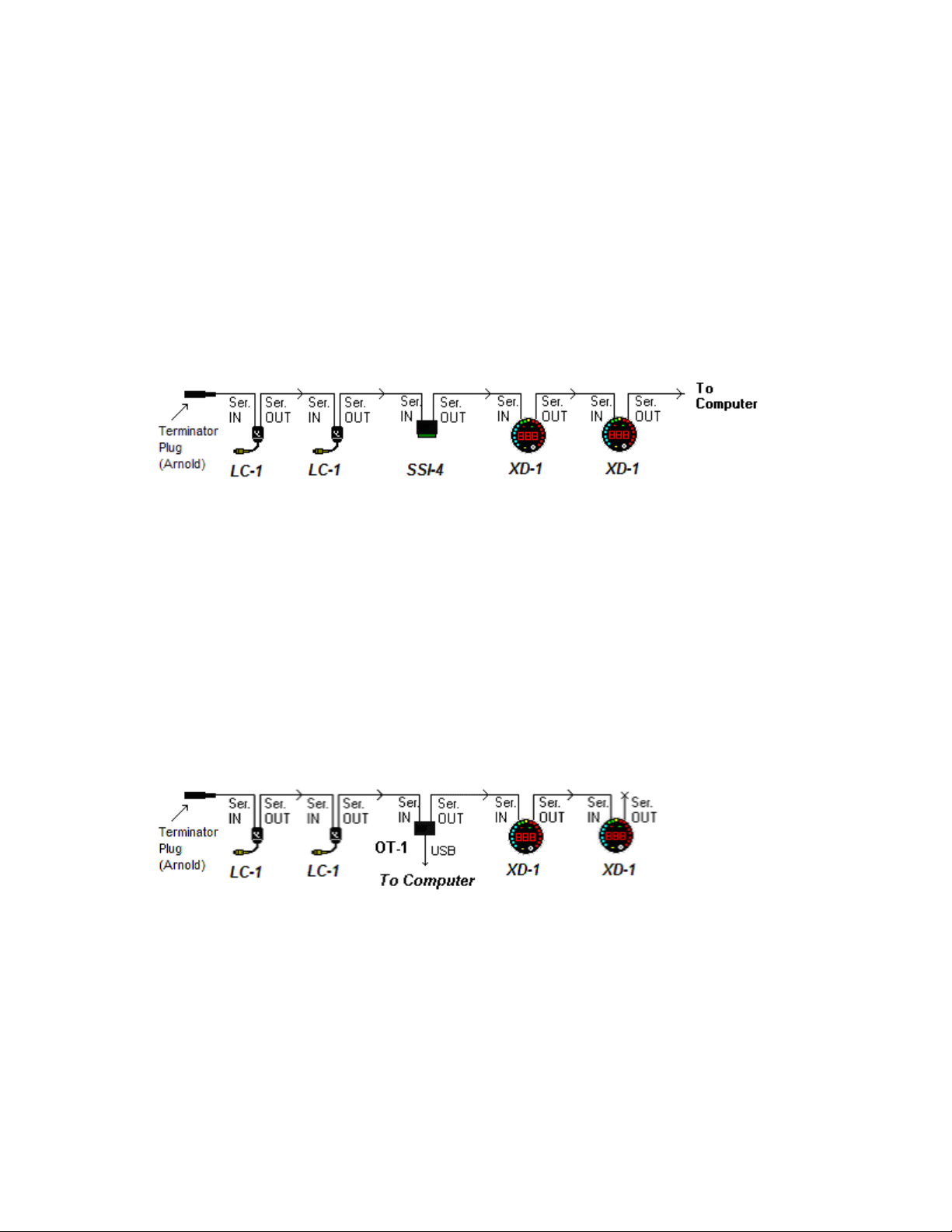
Products are, literally, electrically chained together. The Serial OUT connection of each device is
fed to the Serial IN of the next one in the chain (or a computer if there are no more devices to
add). Here is an example of a simple 6 channel chain:
Because it is the first device in the chain, the Serial IN on the first LC-1 (an MTS lambda (AFR)
measurement module) is terminated with a small plug (named in honor of California’s governor).
Data then flows from the Serial OUT of that device to the Serial IN of the next LC-1, and so on,
down the Log Chain until the data finally reaches a computer for logging. The order of the data
acquisition devices is not important. However, devices which display information from other
devices, like the two dinner plate sized XD-1/XD-16 digital gauges pictured above (diagram may
not be to scale), must be ‘down stream’ of the devices whose data they display. Similarly,
recording devices must be ‘down stream’ of devices whose data is being recorded.
Please note that the OT-1 does not need a terminator plug when it is the first MTS device in a log
chain. In addition to self termination the OT-1 has another significant difference. It can
communicate with a computer either via its Serial OUT connection (like most MTS devices) or via
a built in USB connection. Both the USB and Serial OUT connection can be used at the same
time. For example:
We have replaced the SSI-4 in the previous example with an OT-1. Now the computer can be
connected via USB directly from the OT-1. The computer can ‘see’ and record data from the OT1 and both LC-1s. The Serial OUT connector on the OT-1 is still fed to the gauges. This allows
them to be configured to display OT-1 generated channels as well as the readings from the two
LC-1s in the chain.
- 5 -
1.4 MTS Advantages
With all the excitement about CAN bus communication, one may wonder why use a separate bus
like MTS at all. Truthfully, CAN will most likely become increasingly important in automotive data
acquisition over time. This is why newer Innovate products, like our LM-2 handheld lambda
metering system include support for multiple CAN buses. However, MTS still has some nice
advantages. For instance, it does not require a complicated gateway for connection to a
personal computer. More importantly, at least for data logging purposes, it is a ‘clocked and
synchronous’ data stream.
On a network like CAN, any device can broadcast at any time. There are special ‘collision
detection’ and ‘arbitration’ mechanisms that allow higher priority messages to supersede lower
priority messages. So, the communication rate from any given ‘node’ on the network varies over
time. In contrast, the communication rate from all devices in an MTS chain is even and fixed.
That is, each device is given equal communication priority at very evenly spaced intervals of time.
In operation, this difference can actually be seen on the OT-1 indicator lights. The MTS light,
which blinks in proportion to the MTS packets flowing, blinks very evenly. When connected to a
CAN network, the Vehicle indicator light, which blinks in proportion to complete data sets
acquired, is usually fast but blinks unevenly.
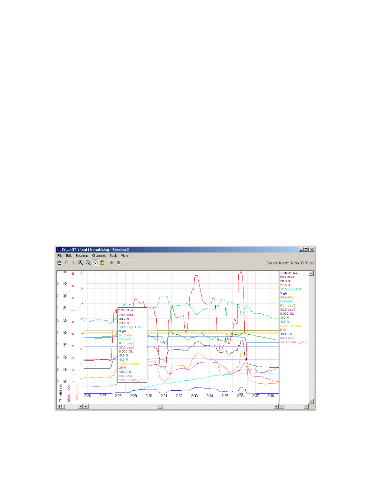
This fixed and common timebase allows MTS compatible acquisition devices to provide very
good data over MTS’s modest bandwidth connection. It also helps to better alight channels, time
wise, from different devices in recorded logs. With asynchronous communication, data is often
time stamped by the logging system based upon when it is received. In a synchronous
communication system, data is inherently time stamped based upon when it was sent. So, when
you, say, place a measurement point in a recorded log you can have good confidence that the
values presented do, in fact, represent the same point in time:
Interestingly, there is an high level protocol for CAN called “TTCAN” (“Time Triggered CAN”) that
is intended for similar applications. However, it is not incorporated into ISO 15765, the current
standard for communicating automotive diagnostic information via CAN.
- 6 -
2. Installing the OT-1
(
For some reason, performance automotive accessories are never as easy to install as they
appear on cable TV. Presumably the commercial breaks cover the point where the happy and
pleasant host scrapes his or her knuckles and begins howling obscenities, after inadvertently
destroying the head of a small fastener which was installed with a Binford brand nuclear powered
driver before being tack welded at the factory…
Fortunately, OT-1 installation is generally less traumatic; though care should be taken not to bang
one’s head on the steering column when searching for the vehicle’s OBD-II connector (an
occurrence that has resulted in several anatomically impossible suggestions here). Please
complete the following installation steps in order. If you have any difficulties, you can utilize our
online support forum at www.tuneyourengine.com
business hours (Pacific Standard Time) Monday through Friday.
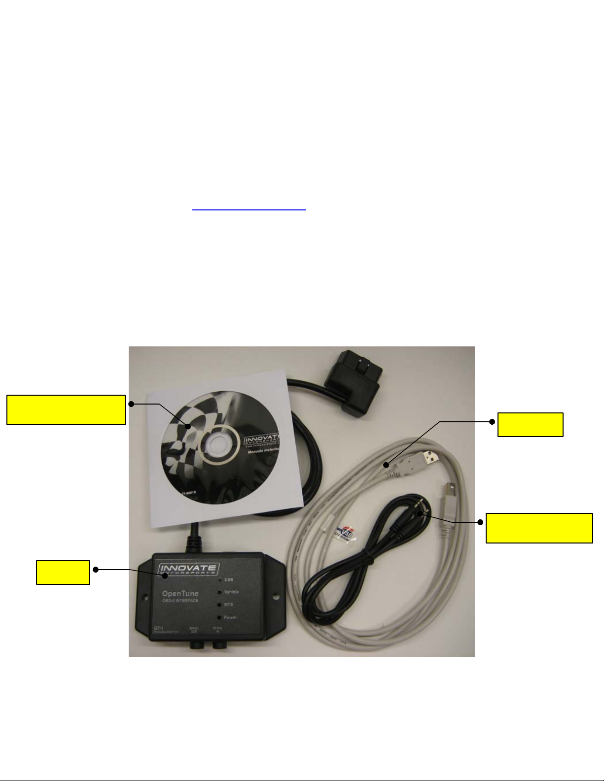
2.1 Confirm the Contents of your Kit
For some reason, most of us never do this even though instructions always recommend it and we
have almost all experienced the frustration of a 96.2% assembled bicycle at 2:14 am on
Christmas Eve. It is a good idea and your OT-1 kit should include the following:
OT-1 kit P/N: 3790
or call us at 949 502-8400 during normal
Software CD
Includes Instructions)
OT-1
USB cable
Daisy-Chain Cable
P/N: 3760
- 7 -
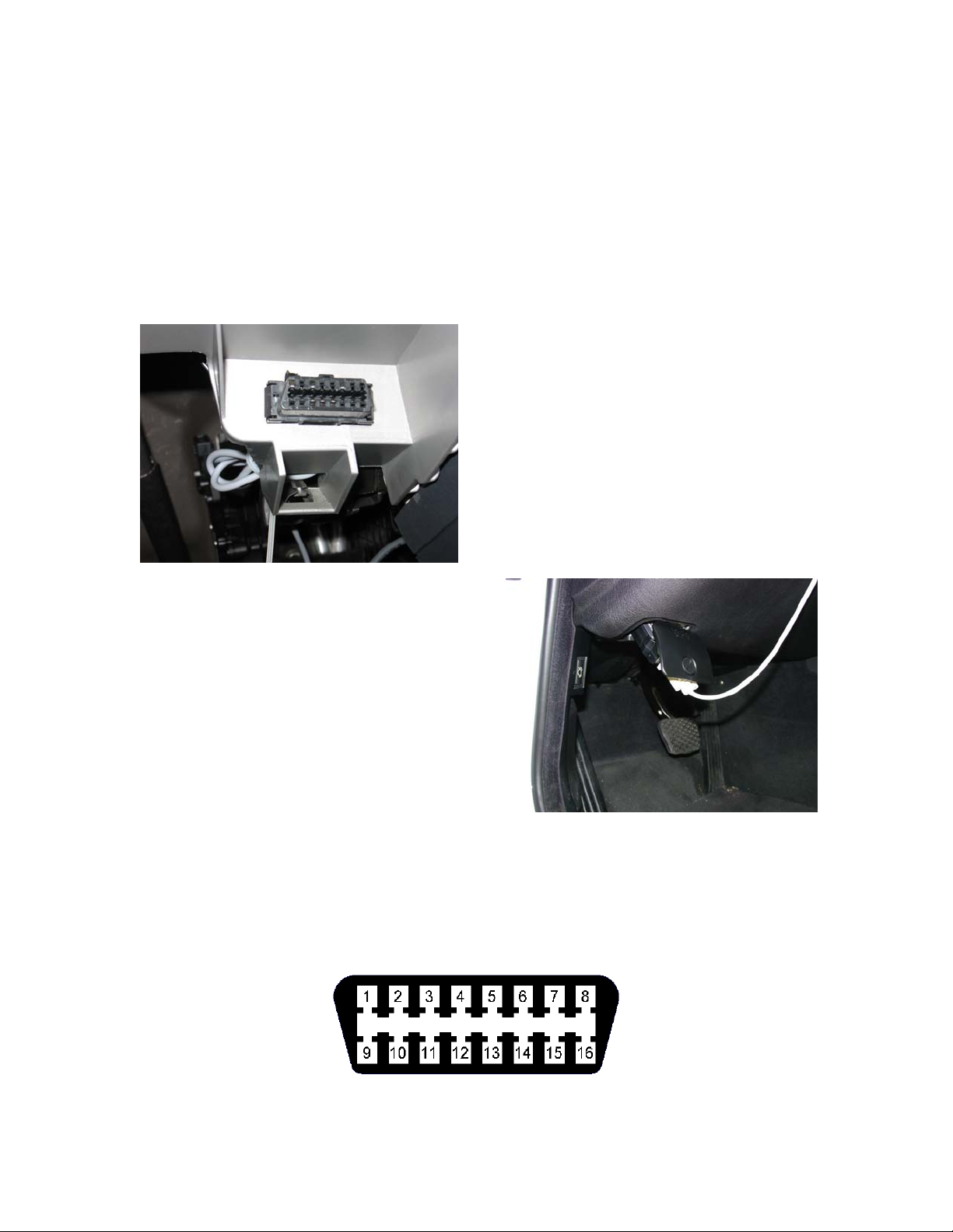
2.2 Locate the OBD-II Connector in your vehicle
As noted, this is typically the most dangerous aspect of OT-1 installation. A safety helmet is
wholly optional, but a flashlight can be extremely helpful. The connector is required to be within
3’ of the driver’s seat in the vehicle and accessible without tools. Generally it is somewhere just
behind the bottom edge of the dashboard, immediately in front of the driver, but it may be in a
relatively obscure place, like hidden behind an ashtray.
If you are unable to locate the connector by inspection your best bet would be to either ask a
mechanic familiar with the make and model vehicle or locate an online hobbyist/enthusiast group
devoted to your vehicle.
Here is a sample OBD-II connector. Please note
that the orientation of the connector varies from
vehicle to vehicle.
For example, in this example, the wide part of the
connector is ‘down’. In other installations this
wide part of the connector will be up. In still
other installations the entire connector may be
‘facing’ the floorboard.
On many newer vehicles the connector is
concealed behind a small door or removable
plastic cover plate.
Also, the connector itself may be covered with a
small, removable, rubber cap.
Although it is not required, once you have located your OBD-II connector you might want to note
which pin positions are populated (you can usually look into the face of the connector and see
which pin positions contain metal contacts). This can be useful in determining what OBD-II
protocols your vehicle supports and is extremely helpful if you need to contact us with a
connectivity or compatibility problem. Looking into the face of the connector the OBD-II pins are
numbered as follows:
- 8 -

2.3 Connect the OT-1 to your vehicle’s OBD-II port
The power pins on an OBD-II connector are always active, so even if your vehicle’s ignition
switch is off, the power light on the OT-1 should immediately illuminate:
[Photo]
If it does not, disconnect the OT-1 and check with a multi-meter or test light between pins 4
(chassis ground) and pin 16 (battery +) on the OBD-II connector. The power pins are fuse
protected and sometimes get shorted out, particularly if the connector is uncovered.
Once the power light is illuminated, and any sparks or burning smells have been eliminated, the
MTS light should become active within a second or so. It will first be steadily on for two seconds.
This indicates that the OT-1 has determined that it is the first device in the ‘Log Chain’. That is,
no other MTS is connected to its Serial IN connector.
Next the light should begin to blink evenly, several times a second. This indicates that the MTS
data stream is running and now available both via the OT-1’s Serial OUT connection and via the
built in USB port.
[Photo – vehicle lit, point out connectors mentioned]
At this point the OT-1 is also attempting to establish a connection to the vehicle’s ECU.
2.4 Turn on the ignition switch and establish an OBD-II connection
By default, the OT-1 is configured to automatically detect the OBD-II protocol being used (ISO
9141, ISO 14230 (KWP2000), J1850-pwm (Ford), J1850-vpw (GM), and ISO 15765 (CAN)), and
to query one value, RPM.
Because the initialization procedures for some protocols are very slow, this initial detection can
take up to 15 seconds. Please note, once the protocol has been detected, reconnection should
be much faster as long as the OT-1 remains connected to the same vehicle.
Once an ECU and protocol have been detected, the Vehicle light will turn on steadily for 2-5
seconds. During this time the OT-1 is interrogating the vehicle for its list of supported features
and waiting for the vehicle to report that certain mandatory monitoring features are now available.
[photo]
After that, the vehicle light will blink as RPM is read. Please note, the blinking of the MTS light
and the vehicle light are on the same ‘scale’. That is, you can compare the speed being
achieved by the ECU with the current channel selections to the MTS sampling speed by directly
comparing the blinking rates of the two lights. Since the speed and performance of OBD-II varies
dramatically between vehicles, this can be extremely useful. It will be discussed further in the
next chapter, which covers configuring the OT-1.
But, in the mean time, congratulations! Unless you intend to permanently mount the OT-1 in your
vehicle (a process that may involve power tools and swearing), hardware installation is now
complete.
- 9 -
 Loading...