

Innovate Motorsports LM-2 User Manual

LM-2
Digital Air/Fuel Ratio Meter
User Manual
Note: This manual assumes that firmware version 1.10 or later is installed on your LM-2
Warning!
The Oxygen Sensor used in this device gets very hot in operation.
Do not touch the hot sensor. Do not let a hot sensor touch a combustible
surface. Do not use the sensor with or near flammable liquids or gases. Failure
to heed these warnings may result in severe burns, explosions or fires.
When installed in the exhaust, the oxygen sensor MUST be connected and
operating with the LM-2 whenever the car is running. An un-powered oxygen
sensor will be quickly damaged when exposed to hot exhaust gases.

TABLE OF CONTENT
1 LM-2.......................................................................................................................................................3
1.1 Main Screen.....................................................................................................................................5
1.2 Status Bar ........................................................................................................................................5
1.3 Configuration Menu Screen .............................................................................................................7
1.4 Recording.........................................................................................................................................8
1.5 Playback...........................................................................................................................................8
2 Air/Fuel Ratio Setup.............................................................................................................................10
2.1 Sensor Calibration..........................................................................................................................10
2.2 Sensor Placement..........................................................................................................................11
2.3 Calibration Schedule......................................................................................................................13
3 Software (LogWorks 3 and LM Programmer)......................................................................................14
3.1 Installing software and Connecting the LM-2 to computer.............................................................14
3.2 Updating Firmware.........................................................................................................................15
3.3 Downloading Logs from Memory Card ..........................................................................................16
4 OBD-II..................................................................................................................................................18
4.1 Locate the OBD-II Connector in your vehicle.................................................................................18
4.2 Selecting Channels on the LM-2....................................................................................................19
4.3 Selecting Channels with the LM Programmer software.................................................................20
4.4 OBD-II Channel Speed ..................................................................................................................21
4.5 Set the Priority of OBD-II Inputs (Optional)....................................................................................23
4.6 Check Vehicle Trouble Codes on the LM-2...................................................................................27
4.7 Clear Vehicle Trouble Codes on the LM-2.....................................................................................27
4.8 Check and Clear Vehicle Trouble Codes with LM Programmer....................................................28
4.9 OBD II Basics.................................................................................................................................29
5 Analog Cable .......................................................................................................................................31
5.1 RPM Input......................................................................................................................................31
5.1.1 Enable/Disable RPM.............................................................................................................31
5.1.2 Configure RPM......................................................................................................................31
5.2 Analog Inputs.................................................................................................................................33
5.2.1 Enable/Disable Analog Inputs...............................................................................................33
5.2.2 Wiring Analog Inputs.............................................................................................................33
5.3 Analog Outputs ..............................................................................................................................34
5.3.1 Programming the analog outputs..........................................................................................34
5.3.2 Advanced output programming.............................................................................................35
5.3.3 Wiring Analog Outputs ..........................................................................................................36
6 Tips, Tricks, & Troubleshooting...........................................................................................................37
6.1 Air/Fuel and Lambda......................................................................................................................37
6.2 General measurement requirements.............................................................................................38
6.3 Vehicles with ‘smog-pumps’...........................................................................................................38
6.4 Single Cylinder Engines.................................................................................................................38
6.5 Diesel Engines...............................................................................................................................38
6.6 Sensor Timing Errors.....................................................................................................................39
6.7 Connecting the LM-2 to simulate a narrow band oxygen sensor ..................................................39
6.8 Attenuating a Tach Signal..............................................................................................................41
6.9 OBD II connection diagnostic trace................................................................................................41
Appendix A: Specifications..........................................................................................................................42
Appendix B: Limited Warranty ....................................................................................................................43
Appendix C: Connectors.............................................................................................................................44
Appendix D: Supported PIDs......................................................................................................................46
Appendix E: Error Codes and Troubleshooting Tips ..................................................................................48
Appendix F: Kit Contents ............................................................................................................................49
2
Document # 31-0008 LM2_Manual_1.3.doc

1 LM-2
The LM-2 is a single or dual channel wideband controller with a built-in OBD II scan tool,
RPM input, four analog inputs, MTS serial I/O, SD memory card recording and two
analog outputs per wideband channel. The following screens will help you get familiar
with the unit.
Front
Mode Button
Press once to
cycle through
channel display
screens. Press and
hold to enter menu.
Cancel Button
Press to cancel out
of menu or to stop
recording.
Record
Press once to
record or press again
to stop recording. Press
and hold to force a new log.
LCD Display
Up Arrow
Scroll through available
channels. Move through
menu
Enter
Accept an entry in the menu
screen.
Down Arrow
Scroll through available
channels. Move through
menu
Left
Inductive Clamp MTS Serial IN MTS Serial OUT
3
Document # 31-0008 LM2_Manual_1.3.doc
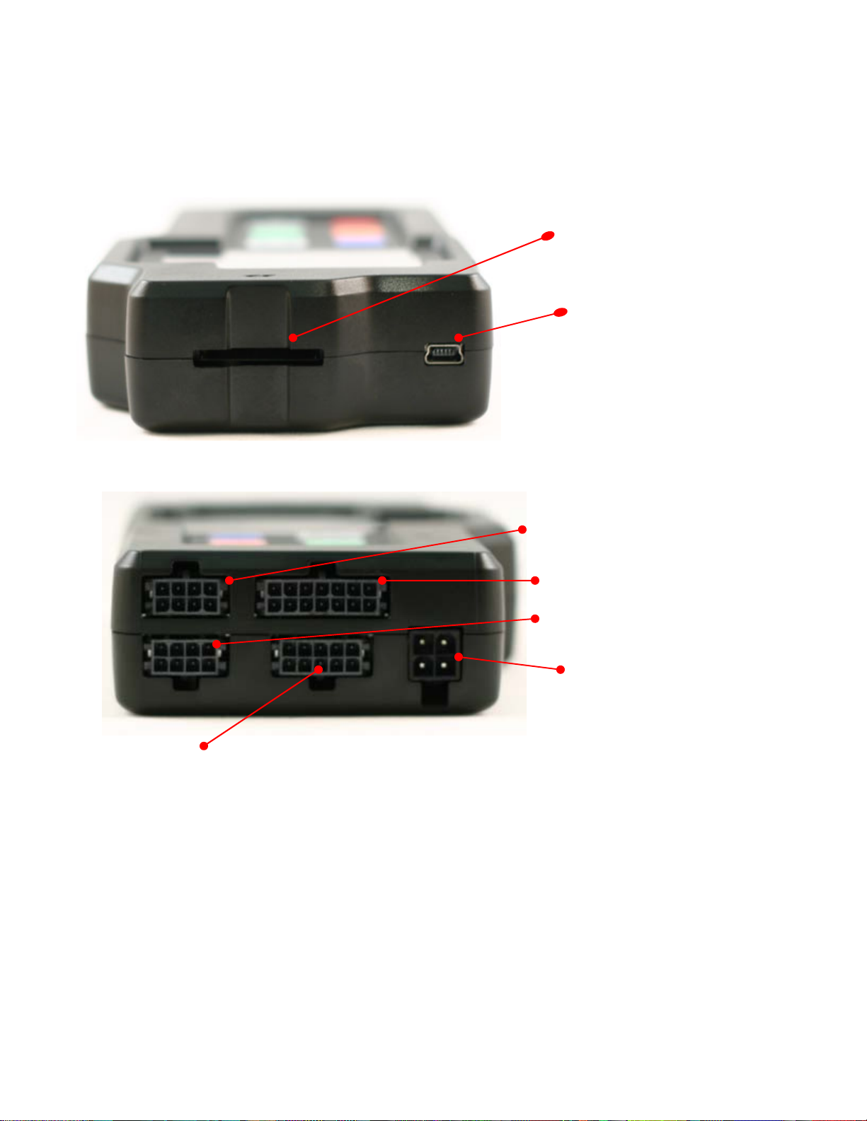
Top
Bottom
SD Memory Card Slot
USB Connector
Sensor Input # 2 (Enabled with
the Dual Channel version)
Analog Cable
Sensor Input # 1
Power
-
4
Document # 31-0008 LM2_Manual_1.3.doc
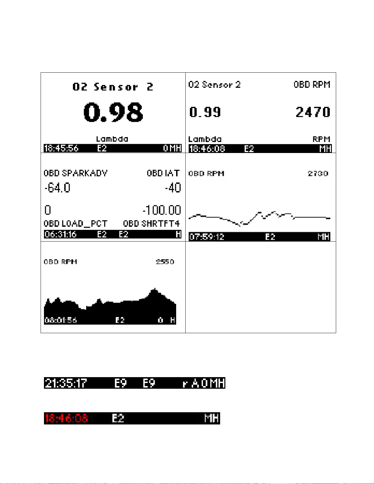
1.1 Main Screen
There are 5 different screen view options. These can be cycled by pressing the Mode
button.
One Channel Two Channels
Four Channels
One Channel Fill Graph
One Channel Line Graph
1.2 Status Bar
The bottom edge of the screen is the status bar and will look something like this:
The left most portion is the current time (which can be set via menu and is set
automatically by LM Programmer).
5
Document # 31-0008 LM2_Manual_1.3.doc
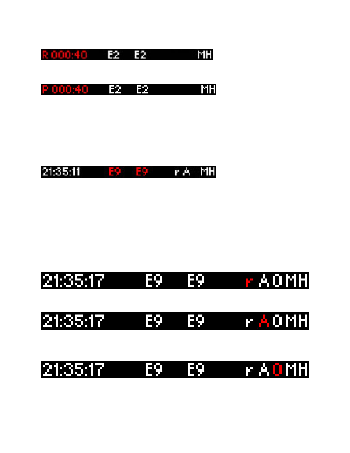
During Recording, an upper case ‘R’ and a counter will display on the lower left:
Counting minutes and seconds of recording.
Similarly, during playback a upper case ‘P’ and a counter will display:
Counting elapsed time during playback.
Note: If Recording does not start (see later section), also look here, the word “Card?”
will appear if no SD card is detected when Record is selected. The word “Full!” will
appear if you have either filled the SD card, or exhausted the available log names (see
section on recording).
Moving to the right, the next two indications are O2 sensor status, which can be one of
the following:
HW - Heater Warm-up
Cal - Calibrating
O2 - Reading O2 context (lambda over 8.something)
L - Reading Lambda (or AFR)
Ex - Error, Check Appendix E for error code meanings and trouble shooting tips
Note: If the LM-2 is a single channel model, the second indication will be blank, not an
error code.
The next indicator, “R”, will appear when a) RPM is selected for logging/use (see
menus) and b) an RPM signal is detected. Note, when RPM is enabled, but no RPM
signal is detected, this symbol will appear in lower case (“r”).
The “A” indicator means that the 4 Analog Inputs are selected for logging/Use (see
menus). It is all or nothing. The display will be blank if disabled.
The “O” indicates that an OBD-II connection is active. This indicator will blink at the
relative ‘sample rate’, which will vary on the number of channels selected and the
vehicle’s protocol. The display will be blank if the unit is not connected to an OBD-II port.
The blinking “M” indicates that MTS serial data is being generated. This will blink at the
relative MTS packet rate (for comparison with the O indicator). If the unit is not the
“head” unit, then this will only blink when packets are being received via the Serial In
6
Document # 31-0008 LM2_Manual_1.3.doc

connector.
Last, “H” indicates that the unit is the MTS head unit. If the unit is not head this indicator
will appear as a “-“
1.3 Configuration Menu Screen
To enter the Configuration Menu Screen press and hold the Mode button.
Navigating the Menu:
“Enter” Accepts
“Cancel” Returns one menu level
“Mode” Returns to Main Screen
Arrows adjust selection or value
“Record” has no effect
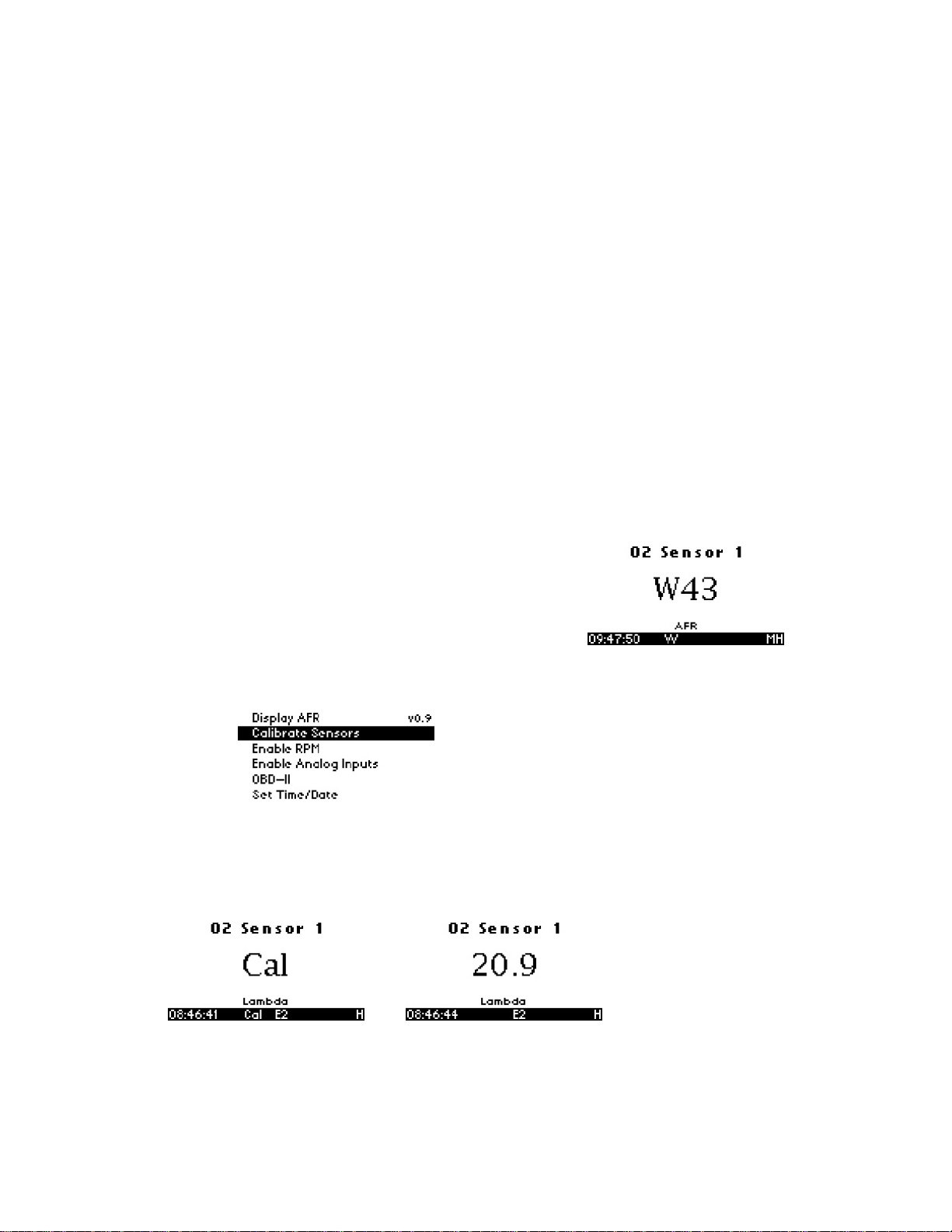
When “Mode” is first pressed, the following choices appear:
• Display AFR or Lambda. The factory default setting is AFR.
• Calibrate Sensors - Free Air Calibrate ALL O2 sensors connected will be
calibrated
• RPM – Enable/Disable RPM and Configure RPM.
• Analog Inputs- Enable/Disable Analog Inputs and Configure Inputs.
• OBD-II - Configure Number of Channels (0-16), Channel Use, Get/Clear DTC
codes Display in Metric/Imperial Units, and Start Trace File.
• Playback Log
• Reverse/Normal Display
• Set Date/Time - Set the current date/time
Important Note: Entering the Configuration Menus will stop recording and
suspend MTS packet output
7
Document # 31-0008 LM2_Manual_1.3.doc

1.4 Recording
To start a record session press the Record button. The LM-2’s display will then inverse
and the status bar will display an upper case ‘R’ and a counter on the lower left hand
corner of the screen. To stop the record session press the Record button a second time.
Note: Loss of power while the LM-2 is recording will lose all data from the current
session being recorded.
When recording is first activated, a file is created. The naming convention is:
mmddyyXX.d32
These are the month, day, and year that the file is created. The XX is to accommodate
multiple files on the same day (counting begins at “00”).
Once a file exists, sessions are appended to it for each additional recording. The
exceptions to this are:
1. The MTS channel count/type has changed
2. The user requests a new log file by pressing and holding “Record” (or holding the
record button on an external XD-16.)
The first instance will occur if devices are added or removed the MTS serial chain , or if
channels are enabled/disabled on the LM-2.
When a new file is created, it will be given the day’s date and a unique counter:
07010800.d32
07010801.d32
Etc
Note: When the LM-2 is recording the display will inverse. In the status bar, an upper
case ‘R’ and a counter will display on the lower left
1.5 Playback
1. Press and hold the Mode button to go into the Configuration Menu Screen.
2. Select Playback log and press the Enter button.
3. A list of available logs present on the memory card will be displayed. Make your
selection and press the Enter button.
Note: Depending on the size of the log the next screen some time to appear.
4. A list of available sessions will be displayed. Make your selection and press the
Enter button.
5. The selected session will now start playing. The status bar will display an upper
case ‘P’ and a counter on the lower left hand corner of the screen.
8
Document # 31-0008 LM2_Manual_1.3.doc

Note: While the session is being played back you can pres the Menu button to cycle
through the different display screens and you may also press the Arrow buttons to
change the displayed channels.
6. To stop the playback you may press the Cancel button at any time or allow the
playback to run it’s course.
9
Document # 31-0008 LM2_Manual_1.3.doc
2 Air/Fuel Ratio Setup
Innovate Motorsports’ ‘Direct Digital’ wideband measurement principal allows you to
calibrate the sensor to compensate for sensor wear. This procedure takes no more than
a couple seconds and it will insure the most accurate readings throughout the oxygen
sensor’s life.
2.1 Sensor Calibration
The calibration procedure requires that the oxygen sensor be in free air, not in the
exhaust.
1. Connect the oxygen sensor to the provided sensor cable and then to the
appropriate port on the LM-2. Note: The dual channel LM-2 model allows you to
connect both oxygen sensors to the unit at the same time to do the calibration
simultaneously.
2. Connect the LM-2 to the cigarette power plug with the provided cigarette power
adapter.
3. The sensor(s) will start warming up. The LM-2
will display WXX, where XX is the percentage of
temperature reached. Notice the status bar
displaying a ‘W’.
4. Next is the calibration procedure. Press and hold the Mode button until the
Configuration Menu appears. Select ‘Calibrate Sensors’ and press the Enter
button.
5. Confirm by selecting ‘Start Sensor Calibration’ and press the Enter button.
6. The display will momentarily display ‘Cal’ and then it will switch to reading a
percentage of oxygen. If the oxygen content now differs from 20.9% by more
than 0.4%, repeat the calibration.
7. The LM-2 is calibrated and ready for use.
10
Document # 31-0008 LM2_Manual_1.3.doc

The LM-2 must be powered by the cigarette adapter (12 volts) in order to
properly heat the Oxygen sensor and measure Air/Fuel. If the unit is only to be
used connected to the OBDII port it will properly function as a scan tool.
2.2 Sensor Placement
Using a bung is the preferred method for mounting the O2 sensor for both catalytic and
non-catalytic cars.
On CATALYTIC CONVERTER equipped vehicles:
Install the oxygen sensor’s bung upstream from the catalytic converter (a bung and
plug is included in the LM-2 kit). The bung must be installed in the exhaust pipe at
the side or on top, NOT on the bottom of the exhaust pipe. Any decent muffler or
exhaust shop can do this for you. The wide-band oxygen sensor is then installed into
the bung to take a reading. (Insert the plug into the bung when not in use). The ideal
position is between 10:00 and 2:00 position.
On NON-CATALYTIC converter vehicles:
You have the option with non-catalytic cars to also use an exhaust clamp as
described below. Use of a bung is the preferred method for mounting the 02 sensor
for both catalytic and non-catalytic cars.
On TURBO CHARGED vehicles:
Install the bung downstream from the turbo but before the catalytic converter. The
high exhaust pressure before the turbo interferes with the lambda measurement and
the high exhaust temperatures encountered there can damage the sensor.
Alternatively you can also use the optional exhaust clamp (part number 3728) to sample
exhaust gases at the end of the tail pipe.
11
Document # 31-0008 LM2_Manual_1.3.doc

Do NOT install the Bung below the 3 o'clock or 9 o'clock position. Condensation
can form in the exhaust pipe and permanently damage the sensor. 6 o’clock is the
absolute worst position to mount the sensor.
Wide band oxygen sensors, like the one shipped with the LM-2, are designed to
work with unleaded gasoline. Use with leaded gasoline will significantly reduce the
lifespan of the sensor. The reduction is directly proportional to the metal content of the
fuel and the tune of the engine. In most cases, a wide band sensor will provide
accurate measurements somewhere between 50 hours and 500 hours with leaded fuel.
WHEN INSTALLED IN THE EXHAUST, THE OXYGEN SENSOR MUST BE
CONNECTED AND OPERATING WITH THE LM-2 WHENEVER THE CAR IS
RUNNING. AN UN-POWERED OXYGEN SENSOR WILL BE DAMAGED WHEN
EXPOSED TO EXHAUST GAS IF NOT PROPERLY POWERED.
The maximum temperature of the sensor at the bung (the sensor hexagon)
should not exceed 500 oC or 900 oF. If these temperatures are exceeded in your
application you should either install a double length bung (one inch) or the Innovate
Motorsports Heat-Sink Bung extender (HBX-1).
The double length bung is also recommended for situations where airflow is restricted.
It is NOT a good idea to do a sensor warm-up prior to starting the vehicle.
Depending on the climate and the sensor position in the exhaust, condensation can
form in the exhaust pipes. This condensation could then be blown by the exhaust
stream against the hot sensor when the car is started. The resulting heat shock can
permanently damage the sensor.
12
Document # 31-0008 LM2_Manual_1.3.doc

2.3 Calibration Schedule
Normally aspirated (daily driver)
- Calibrate before installation of new sensor
- Calibrate new sensor again after 3 month of use
- Thereafter calibrate once a year or every 20,000 miles, whichever comes first
Turbo Application, daily driver (tuned rich)
- Calibrate before installation of new sensor
- Calibrate new sensor again after 3 month of use
- Thereafter calibrate twice a year or every 10,000 miles, whichever comes first
Race Application
- Calibrate before first installation of new sensor
- Calibrate once per race weekend
- For added sensor life we also recommend our optional double length bung (part
number 3764
Dyno use:
- Calibrate a new sensor
- Calibrate every 2-3 days, depending on usage
13
Document # 31-0008 LM2_Manual_1.3.doc
3 Software (LogWorks 3 and LM Programmer)
It is important to install the provided software on the computer prior to connecting
the LM-2. Failure to do so may lead to connection complications.
3.1 Installing software and Connecting the LM-2 to computer
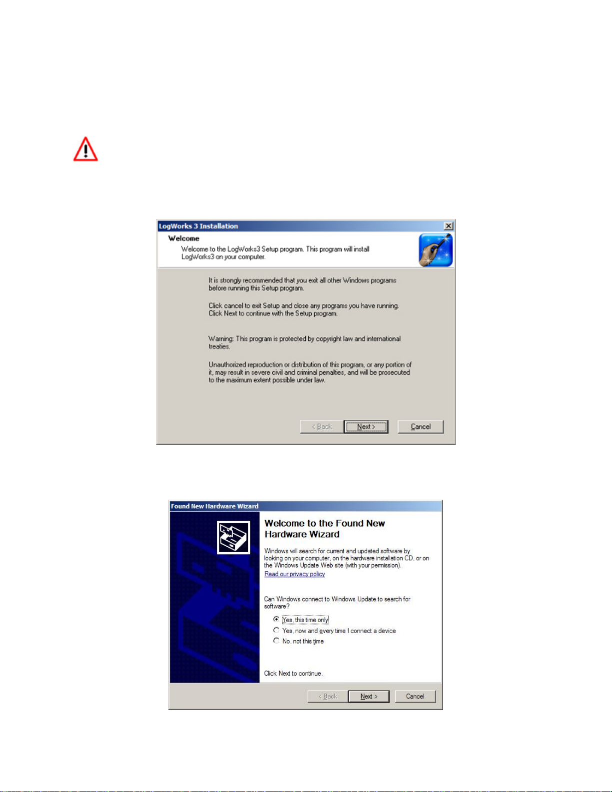
1. Install the CD that came with your LM-2 in your personal computer.
2. The installer will automatically start, follow the prompts to install the software.
3. Connect one end of the USB cable to the LM-2 and the other end to your computer.
4. Power up the LM-2.
5. Windows will now recognize the device and prompt the “New Hardware Wizard.”
Click Next.
14
Document # 31-0008 LM2_Manual_1.3.doc
6. Select “Install the Device Automatically” and click Next.
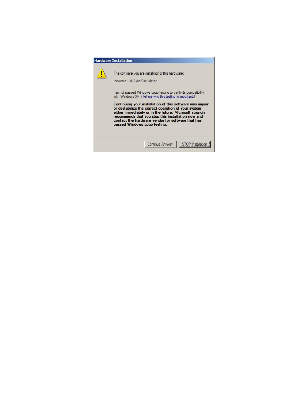
7. A progress screen will appear. During this installation process the screen below will
pop up. Click “Continue Anyway.”
8. The last screen will inform you that the unit has been successfully installed. Click
“Finish.” The unit is installed and ready to use.
3.2 Updating Firmware
1. Connect the LM-2 to your computer with the provided USB cable.
2. Power up the LM-2.
3. Launch LM Programmer. The LM Programmer application can be launched from
Start->Programs->LogWorks3->LM Programmer from the Windows task bar.
4. Once connected the LM Programmer will display the current version of the
firmware that is installed in the LM-2. Do not update the firmware if the versions
are the same. A firmware update should only be necessary if there has been a
new release.
5. On the very first tab of LM Programmer you will see a button labeled “Update
Firmware,” click this button.
15
Document # 31-0008 LM2_Manual_1.3.doc
 Loading...