

Ingersoll Rand YSC033G, YSC120F, YSC063G, YZC048F, YZC036E Owner's Manual
...
SAFETYWARNING
Only qualified personnel should install and service the equipment.The installation,
starting up, and servicing of heating, ventilating, and air-conditioningequipment can
be hazardous and requiresspecific knowledge and training. Improperly installed,
adjusted or altered equipment byan unqualified person could result in death or
serious injury.When working on the equipment, observe all precautionsin the
literatureand on the tags, stickers, and labels that are attached to the equipment.
1
32
4 5
6 7
Owner Manual
Packaged Rooftop Air Conditioners
Precedent™ - Gas/Electric
3to10Tons-60Hz
Model Numbers:
YSC036E - YSC060E
YSC072F - YSC120F
YSC033G - YSC063G
YZC036E, YZC048F, YZC060E
YZC072F - YZC120F
YHC036E - YHC072E
YHC072F - YHC120F
Warnings, Cautions, and Notices
Read thismanual thoroughly before operating or servicing thisunit. Safety
advisories appearthroughout this manual asrequired.Your personalsafety
andthe proper operationof this machinedepend uponthe strict observance
of these precautions.
Important Environmental Concerns
Scientific research has shown that certain man-made chemicals can affect
the earth’snaturally occurringstratospheric ozone layer when released to
the atmosphere. In particular, several of the identified chemicals that may
affect the ozone layer are refrigerants that contain Chlorine, Fluorine and
Carbon (CFCs) and those containing Hydrogen, Chlorine, Fluorine and
Carbon (HCFCs).Not all refrigerants containing these compounds havethe
same potentialimpact to the environment.Traneadvocates the responsible
handling of all refrigerants-including industry replacements for CFCs such
as HCFCs and HFCs.
Important Responsible Refrigerant Practices
Trane believes that responsible refrigerant practices are important to the
environment, our customers, and the air conditioning industry. All
technicianswho handle refrigerants mustbe certified.The Federal CleanAir
Act (Section 608) sets forth the requirements for handling, reclaiming,
recovering and recycling of certain refrigerants and the equipment that is
used inthese service procedures. In addition,some states or municipalities
may have additional requirements that must also be adhered to for
responsible management of refrigerants. Know the applicable laws and
follow them.
The three types of advisories are defined as follows:
WARNING
Indicates apotentially hazardous situation which,
if not avoided, could result in death or serious
injury.
CAUTION
Indicates apotentially hazardous situation which,
if not avoided, could result in minor or moderate
injury.It could also beused to alertagainst unsafe
NOTICE
Indicates a situation that could result in
equipment or property-damage only accidents.
WARNING
Proper Field Wiring and Grounding Required!
Failure to followcode could result in death or seriousinjury. All field wiring
MUST beperformed by qualified personnel. Improperlyinstalled and grounded
field wiring poses FIRE and ELECTROCUTION hazards.To avoid these hazards,
you MUST follow requirementsfor field wiring installation and grounding as
described in NEC and your local/state electrical codes.
WARNING
Personal Protective Equipment Required!
Installing/servicing this unit could result in exposure to electrical, mechanical
and chemical hazards. Before installing/servicing this unit, technicians MUST
put on all Personal Protective Equipment (PPE) recommended for the work
being undertaken.ALWAYS refer toappropriate MSDS sheets and OSHA
guidelines for proper PPE.When working with or aroundhazardous chemicals,
ALWAYS refer to the appropriate MSDS sheets and OSHA guidelines for
information on allowable personal exposurelevels, proper respiratory
protection and handling recommendations. If there is a risk of arc or flash,
technicians MUSTput on all necessary Personal Protective Equipment (PPE) in
accordance with NFPA70Efor arc/flash protection PRIOR to servicing the unit.
Failure to followrecommendations could result in death or serious injury.
General Information
Important: Remember the following instructions at all times.
WARNING
Hazard of Explosion or Fire!
Do not store or use gasoline or other flammable vapors and liquids in the vicinity
of this or any other appliance.
IFYOU SMELL GAS, follow instructions below:
• Do not try to light any appliance.
• Do not touch any electrical switch.
• Do not use any phone in your building.
• Open windows and doors.
• Alert others and evacuate building immediately.
• Froma phoneoutside of thebuilding, immediatelycall yourgas supplier.Follow
thegas supplier's instructions.If youcan not reachyour gassupplier,call the fire
department.
Failure to followinstructions listed above could result in death or serious injury
and equipment or property damage.
WARNING
Safety Hazards!
• Do not use this furnace if any portion has been under water as it may have
rendered the unit hazardous to operate.Immediately call a qualified service
technician toinspect the furnace and to replace anypart or the control system
and any gas control which has been under water.
• Should overheating occur,or the unit gas valve fail to shut off, close the gas
valve to the furnacebefore shutting off the electrical supply.
Failureto follow instructions couldresult in death, serious injuryand equipment or
property damage.
The unit has a complex design.To ensure that it performs safely and gives
long lastingservices, some of themaintenance work must be performedby
a qualified service person.
When aservice person is referred to inthis manual it is describing a service
technicianwho has had special training or a number ofyear sexperience in
servicingthis type of equipment.It is yourresponsibility to selecta qualified
service company that can provide a service person of this caliber.
WARNING
Safety Hazards!
• Never perform anymaintenance procedures until the electrical power to the
unit is turned off.
• Neverperform anymaintenance proceduresuntil thegas valveis the gassupply
line is turned off.
• Never remove anypanels from the unit while it isoperating.
• Never remove panels or parts fromthe unitthat arenot discussed in this
manual.
• Never cover the unit since it is designed to operate year round.
Failure to followinstructions could result in death or serious injury.
Thermostat
Room thermostats are delicate temperature sensing controls.Their main
function is to energize and de-energize the heating or cooling circuit to
maintain the temperature setting you select.
Manythermostats contain aroom thermometer toindicate theapproximate
room temperature and a temperature scale at the adjustment indicator to
select the desired indoor air temperature. In addition, most thermostats
have a selector mode switchwith Heat, Off and Cool positions and a fan
switch with On and Off positions.
When the switch is positioned atOff your unit will not operate in either the
heat or cool modes. If the selector switch is set at Heat the unit will
automatically cycle on andoff to maintain the desired temperature setting.
The unit will also operate automatically when the selector switch is
positioned at Cool.
The fan selector switchcan be used to operate the indoor fan continuously
by positioning it at On.When set toAuto the fan will only operate when
required during the heating or cooling cycles.
Toensure that the thermostat operates properly, it must be level and
positioned to avoid the influence of such external heat sources as lamps,
televisions or other heat producing appliances.
Note: Single Zone VAVis designed to be used with azone sensor. If a unit
is configured for Single ZoneVAV operation but is connected to a
thermostat, the control will revert to multi-speed (2-Speed) indoor fan
control and staged compressorcontrol. Thisdrastically reduces the energy
savings available with this design.
Note: eFlex™ is designed to be used with a zone sensor. If a unit is
configured for variable speed compressor operation but is connected to a
thermostat, the control will revert to multi-speed indoor fan control and
staged compressor control. This drastically reduces the energy savings
available with this design.
Note: Modulating gas heat is designed to be used with a zone sensor. If a
unit is configured for modulating gas heat operation but is connected to a
thermostat, the control will revertto a CV heating operation, but will utilize
the user selected discharge air heating setpoint for discharge air
temperature control of the modulating gas heat.
Air Filters
Filters are to be used with this unit. Units ship from the factory with filters
installed.
It is very important tok eep thecentral duct system air filters clean. Be sure
to inspect them at least once each month when the system is in constant
operation. (Innew homes, checkthe filters every week forthe first 4 weeks.)
See Table 1 for the required filter size(s).
If youhave disposable typefilters, replace them withnew filters of thesame
type and size. Do not attempt to clean disposable filters.
Permanent type filters can be cleaned by washing them with a mild
detergent and water. Ensure that the filters are thoroughly dry before
reinstalling them in the unit (or duct system).
It maybe necessary to replace permanentfilters annually if washing failsto
clean the filter, be sure to use the same type and size as was originally
installed.
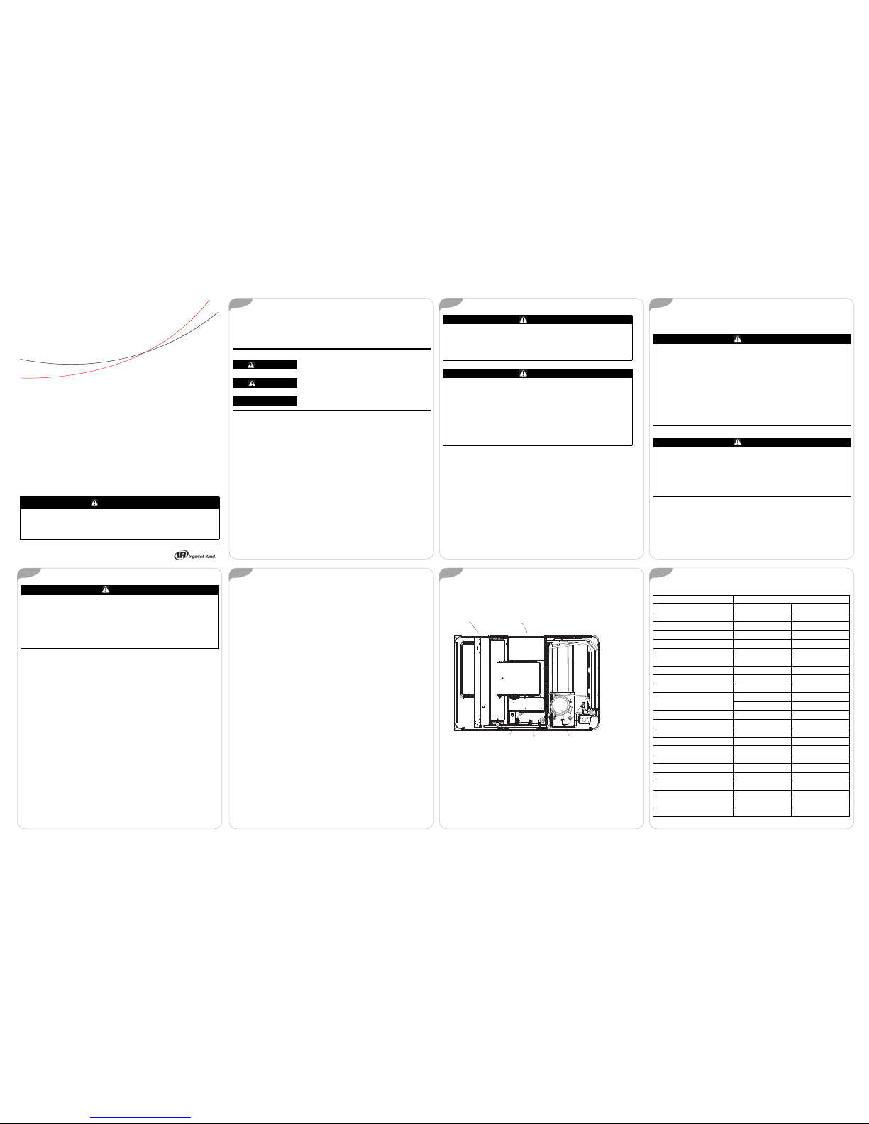
Figure 1. Gas unit overview
RETURN AIR
SUPPLY AIR
PRESSURE SWITCH
GAS VALVE
COMPRESSOR
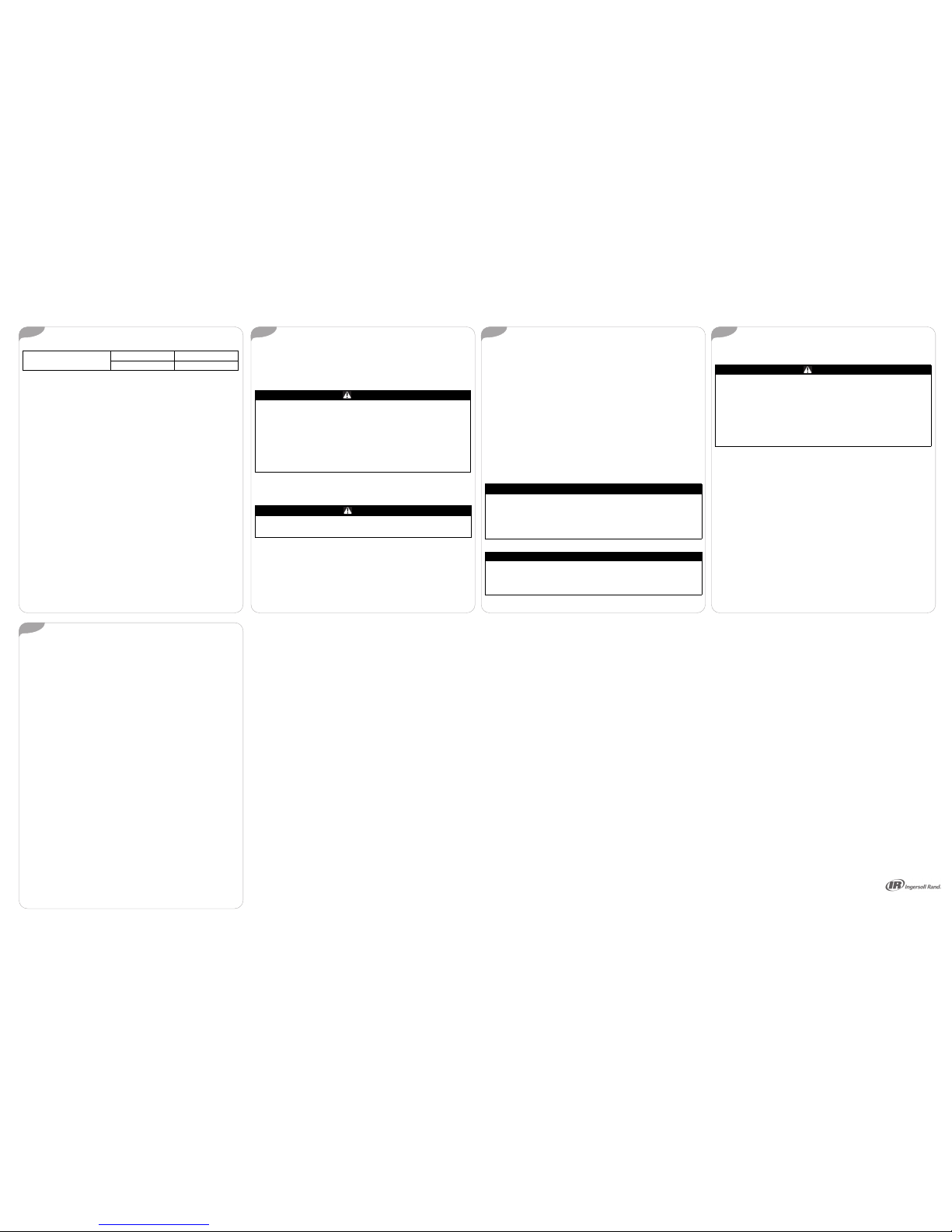
Table1. Recommended standard filters
Unit Model Number Filter Size
Inches Millimeters
YH/SC036E*, YHC037E* (2) 20x30x2 (2) 508x762x50
YZC036E* (2) 20x30x2 (2) 508x762x50
YSC048E* (2) 20x30x2 (2) 508x762x50
YZC048F* (4) 16x25x2 (4) 406x635x50
YSC060E* (2) 20x30x2 (2) 508x762x50
YZC060E* (4) 16x25x2 (4) 406x635x50
YZC072F* (4) 20x25x2 (4) 508x635x50
YZC090F* (4) 20x25x2 (4) 508x635x50
YZC102F* (4) 20x25x2 (4) 508x635x50
YZC120F*
(2) 20x30x2 (2) 508x762x50
(3) 20x25x2 (3) 508x635x50
YSC033-063G* (2) 20x35x2 (2) 508x635x50
YHC047E*, YHC048* (4) 16x25x2 (4) 406x635x50
YHC060*, YHC067E* (4) 16x25x2 (4) 406x635x50
YSC072F* (4) 16x25x2 (4) 406x635x50
YSC090F* (4) 16x25x2 (4) 406x635x50
YHC072F* (4) 20x25x2 (4) 508x635x50
YHC074F* (4) 20x25x2 (4) 508x635x50
YSC092F* (4) 20x25x2 (4) 508x635x50
YSC102F* (4) 20x25x2 (4) 508x635x50
YSC120F* (4) 20x25x2 (4) 508x635x50
YHC092F* (4) 20x25x2 (4) 508x635x50
YHC102F* (4) 20x25x2 (4) 508x635x50
January 2017
RT-SVU03L-EN
© 2017 Ingersoll Rand All Rights Reserved
Ingersoll Rand (NYSE:IR)advances the quality of life by creating comfortable,sustainable and efficient
environments. Ourpeople and our family of brands—including Club Car®, Ingersoll Rand®,Thermo
King®andTrane®—work together toenhance the quality and comfort of air inhomes and buildings;
transport andprotect food and perishables; and increase industrial productivity andefficiency. Weare a
global business committedto a world of sustainable progress and enduringresults. For more
information, visit www.ingersollrand.com.
Ingersoll Randhas a policy ofcontinuous product and productdata improvement andreser vesthe right to changedesign
and specificationswithout notice.
Weare committed to using
environmentally consciousprint
practices thatreduce waste.
9
1110
12 13
14 15
8
Heating System
Heating Cycle Operation
Yourunit's heating system has a solid-state electronic ignition control that
lights thefurnace burners eachtime the thermostat callsfor heat. Atthe end
of each heating cycle the furnace burners are extinguished.This type of
system is called Direct Spark Ignition (DSI).
A normal heating cycle begins when the air temperature drops below the
thermostat setting.The thermostat then energizes the heating electrical
circuit thatstarts and controlsthe furnace burners. Shortlyafter the burners
ignite theindoor fan starts and circulateswarm air through the conditioned
space.
When the airtemperature rises to the thermostat setting thethermostat deenergizes the heating electrical circuit, which in turn extinguishes the
burners.The indoor fan continues to circulate warm air until most of the
heat is removed from the unit's combustion chamber.
Safety Controls
• Yourunit is equipped with an automatic reset safety limit control to
prevent overheating. When this control opens, it shuts down the
heating electrical circuit until the unit cools down sufficiently.
Inadequate airflow (i.e., caused by dirty filters or defective fan motor)
maycause the unitto cycle onand off asthe limit tripsand automatically
resets. If you suspect that the unit is cycling on its limit control,
immediately contact a service person for instructions.
• If flames from the burner are not properly drawn into the heat
exchanger, a flame rollout protection control will open causing the
furnace to shut off. The cause must be investigated by a qualified
service person.
• If installed, the condensate overflow switch will shut down the unit
before a drain pan overflow occurs.
YHC120F*
(2) 20x30x2 (2) 508x762x50
(3) 20x25x2 (3) 508x635x50
Table1. Recommended standard filters (continued)
Heating System Start-Up
Because your unit has an automatic ignition system, it is easy to start the
heating cycle at the beginning of the heating season. In order for the unit
to operate properly and safely, the furnace needs air for both combustion
and ventilation. Check to make sure that all air openings are unobstructed
and there is adequate clearance around the unit to provide good air flow.
1. Set the thermostat's heating adjustment lever at its lowest setting.
2. Move the selector switch to the Off position.
3. Turn off all electric power to the unit.
4. This unit is equipped with an ignitiondevice whichautomatically lights
the burners.
5. Remove the access panel that contains the following label:
WARNING
HazardousVoltage w/Capacitors!
Failureto disconnect power and dischargecapacitors before servicing could result
in death or serious injury.Disconnect all electricpower, including remote
disconnects and discharge all motor start/runcapacitors before servicing. Follow
proper lockout/tagoutprocedures to ensure the power cannot be inadvertently
energized. For variablefrequency drives or other energy storing components
provided byTraneor others, referto the appropriate manufacturer’sliterature for
allowable waiting periods fordischarge of capacitors. Verifywith an appropriate
voltmeter that all capacitors have discharged.
For additional information regardingthe safe discharge of capacitors, see PRODSVB06A-EN
WARNING
Risk of Burn!
NEVER attempt to manually light the burner! Failureto follow this instruction
could result in serious injury.
Figure 2. Label
REMOVE THIS PANEL
TO GAIN ACCESS TO
THE GAS VALVE
6. Change the ON/OFF switch to the OFF position.
Note: Somevalves require the knobto be pushed in slightlybefore turning.
7. Wait (5) minutes to clear out any gas. If you then smell gas, STOP! Refer
to thewarnings provided in the “General Information”section. If you do
not smell gas, go to the next step.
8. Change the ON/OFF switch to the ON position.
9. Replace panel removed in step 5 above.
10.Turnon all electric power to unit.
11.Set thermostat to desired temperature and move the selector switch to
the ON position. The unit will now operate automatically.
12.If the unit will not operate, follow the instructions "ToTurn Off GasTo
Unit" (underHeating System Shutdown) andcall your service technician
or gas supplier.
Important: The unit is to be adjusted to obtain an air rise within that
specified on the nameplate.
Heating System Shutdown
Toshut down the heating systemfor brief periods of time simply adjust the
thermostat selector switch to the "Off" position.
NOTICE
Property Damage!
If the unit isshut down during the cold weather months, provisionsmust be taken
to prevent freeze-upof all waterpipes and water receptacles. Whenever your
house or building is to be vacant, arrangeto have someone inspect your structure
for proper temperature.This is veryimportant in below freezing weather. If forany
reason your furnace should failto operate, damage such as frozen water pipes
could result.
NOTICE
Coil Freeze-up!
Failure to followinstructions below could result in coil damage. Drain and vent
coils when not in use.Trane recommends glycol protection in all possible freezing
applications. Use a glycol approved for use with commercial cooling and heating
systems and copper tube coils.
HowToTurn Off Gas To Unit
1. Set the thermostat to lowest setting.
2. Turn off all electric power to the unit if service is to be performed.
3. Remove the access panel that contains the label shown in Figure 2.
4. Change ON/OFF switch to the "OFF" position.
5. Replace panel removed in step 3 above.
WARNING
HazardousVoltage w/Capacitors!
Failureto disconnect power and dischargecapacitors before servicing could result
in death or serious injury.Disconnect allelectric power, including remote
disconnects and discharge all motor start/runcapacitors before servicing. Follow
proper lockout/tagoutprocedures to ensure the power cannot be inadvertently
energized. For variablefrequency drives or other energy storing components
provided byTraneor others, referto the appropriate manufacturer’sliterature for
allowable waiting periods fordischarge of capacitors. Verifywith an appropriate
voltmeter that all capacitors have discharged.
For additional information regardingthe safe discharge of capacitors, see PRODSVB06A-EN
Heating System Maintenance
Complete the following unit inspections and service routines at the
beginning of each heating season.
Refer to the warnings in “General Information” regarding combustible
materials and what to do if you smell gas.
Important: These steps should only be performed by a qualified service
technician.
1. Inspect the control panel wiring and heating controls to make sure
connections are tight and wiring insulation is intact.
2. Turn the unit on and off at the thermostat to be sure the ignition control
and spark electrode are operating properly.
3. Turn off the gas supply with the unit operating to verify that the gas
valves closes and that a re-ignition cycle is initiated by the ignition
control.
4. Check the operation of the gas ignition system.
5. Check the burner manifold pressure. A 1/8 inch pipe plug is provided in
the gas valve for this purpose.
6. Visuallyinspect all of the unit's flue product passageways for excessive
deposit build up and corrosion. If build up or corrosion is apparent,
perform the necessary repairs.
7. Arrange for aqualified serviceman toinspect the unitevery other heating
season to maintain safe and efficient operation.
8. Visuallycheckthe main burner flames.Theyshould be bright blueflames
extending into the heat exchangersections.
9. Never store anythingflammable or combustible around or near the unit.
Condensate Overflow Sensor (Optional)
If installed, the condensate overflow switch will shut down the unit before
a drain pan overflow occur s.
© 2017Ingersoll Rand All rights reserved
RT-SVU03L-EN 13 Jan2017
Supersedes RT-SVU03K-EN (06Nov 2015)
 Loading...