

Page 1

Before installing or starting this unit for the first
time, this manual should be studied carefully to
obtain a working knowledge of the unit and/or the
duties to be performed while operating and
maintaining the unit.
RETAIN THIS MANUAL WITH UNIT. This Technical
manual contains IMPORTANT SAFETY DATA and
should be kept with the unit at all times.
Ingersoll Rand
X-Series System Automation
Interconnect Guide
Ingersoll Rand Compressors
C.C.N. :
More Than Air. Answers.
Online answers: http://www.air.irco.com
REV. : A
DATE : APRIL 2007
1
Page 2

SECTION 1 — TABLE OF CONTENTS
SECTION 1 — TABLE OF CONTENTS.................................2
SECTION 2 — INTRODUCTION.........................................3
SECTION 3 — SAFETY......................................................3
INSTALLATION ................................................................3
OPERATION.....................................................................3
MAINTENANCE AND REPAIR ............................................4
SECTION 4 — X4I SYSTEM OVERVIEW ..............................5
SECTION 5 — X8I SYSTEM OVERVIEW ..............................6
SECTION 6 — VSD OVERVIEW ..........................................7
SECTION 7 — ASSISTANCE ..............................................8
SECTION 8 — INTERCONNECT DRAWINGS .......................8
INTELLISYS CONTROLLER E-PROM
RECOMMENDATIONS.......................................................8
INTELLISYS CONTROLLER INTERCONNECT
RECOMMENDATIONS.......................................................8
APPENDIX A — ir-485, irV-485, and RS485 Direct
Interconnect Drawings To Ingersoll Rand Intellisys
Controlled Compressor ............................................9
APPENDIX B — ir-PCB Interconnect Drawings To
Ingersoll Rand Intellisys Controlled And CMC Sierra
Compressors ..........................................................17
APPENDIX C — ir-PCB Interconnect Drawings To
Ingersoll Rand Pressure Switch Controlled
Compressors ..........................................................51
APPENDIX D — VSD Box Interconnect Drawings To
Ingersoll Rand Non-Nirvana VSD Compressors .......92
2
Page 3

SECTION 2 — INTRODUCTION
The X - SERIES AUTOMATION is a family of specialized
controllers designed to provide safe, reliable, and
energy-efficient control of your compressed air system.
X4I
The X4I is capable of controlling positive displacement
air compressors. The compressors may have electropneumatic or microprocessor based controls. The X4I is
completely customizable to meet the specific needs of
your compressed air system.
SECTION 3 — SAFETY
WARNING :
!
WARNING :
WARNING :
!
WARNING :
INSTALLATION
Risk of Danger
Risk of Electric Shock
Risk of High Pressure
Consult Manual
• Before installing or operating the X-
Series Automation System, take time to
carefully read all the instructions
contained in this manual, all compressor
manuals, and all manuals of any other
peripheral devices that may be installed
or connected to the unit.
• Electricity and compressed air have the
potential to cause severe personal injury
or property damage.
• The operator should use common sense
and good working practices while
operating and maintaining this system.
All applicable codes should be strictly
adhered to.
• Maintenance must be performed by
adequately qualified personnel that are
equipped with the proper tools.
• Installation work must only be carried
out by a competent person under
qualified supervision.
• A fused isolation switch must be fitted
between the main power supply and the
X-Series Automation System.
• The X-Series Automation System should
be mounted in such a location as to
allow operational and maintenance
X8I
The X8I is an advanced system controller designed to
provide safe, reliable, and energy-efficient management
of your compressed air system. The X8I is capable of
controlling up to eight (8) positive displacement air
compressors. The compressors may be fixed speed,
variable speed or multi-step and have electro-pneumatic
or microprocessor based controls. The X8I is uniquely
configurable and customizable to meet the specific
needs of some of the most complex compressed air
system. Additionally, the X8I control network can expand
to include monitoring and control of various compressed
air system components.
access without obstruction or hazard
and to allow clear visibility of indicator
at all times.
• orms are required to
If raised platf
provide access to the X-Series
Automation System, they must not
interfere with normal operation or
obstruct access. Platforms and stair
should be of grid or plate construction
with safety rails on all open sides.
OPERATION
• The X-Series Automation System must
only be operated by competent
personnel under qualified superv
•
Never remove or tamper with safety
devices, guards or insulation materia
fitted to the X-Series Automation System
•
The X-Series Automation System must
only be operated at the supply voltage
and frequency for which it is designed.
•
When main power is switched on, lethal
voltages are present in the electrical
circuits and extreme caution must be
exercised whenever it is necessary to
carry out any work on the unit.
• uch
Do not open access panels or to
electrical components while voltage is
applied unless it is necessary for
measurements, tests or adjustment
Such work should be carried out only b
a qualified electrician equipped with the
correct tools and wearing appropriate
protection against electrical hazards.
•
All air compressors and/or other
equipment connected to the unit s
have a warning sign attached stating
“THIS UNIT MAY START WITHOUT
WARNING” next to the display pane
3
s
s
ision.
ls
.
s.
y
hould
l.
Page 4

• If an air compressor and/or other
equipment connected to the unit is to be
started remotely, attach two warning
signs to the equipment stating “THIS
UNIT CAN BE STARTED REMOTELY”.
Attach one sign in a prominent location
on the outside of the equipment, and
the other sign inside the equipment
control compartment.
MAINTENANCE AND REPAIR
• Maintenance, repairs or modifications
must only be carried out by competent
personnel under qualified supervision.
• If replacement parts are required, use
only genuine parts from the original
equipment manufacturer, or an
alternative approved source.
• Carry out the following operations
before opening or removing any access
panels or carrying out any work on the
X-Series Automation System:
i. Isolate the X-Series Automation
System from the main electrical
power supply. Lock the isolator
in the “OFF” position and remove
the fuses.
ii. Attach labels to the isolator
switch and to the unit stating
“WORK IN PROGRESS - DO NOT
APPLY VOLTAGE”. Do not switch
on electrical power or attempt to
start the X-Series Automation
System if such a warning label is
attached.
• Make sure that all instructions
concerning operation and maintenance
are strictly followed and that the
complete unit, with all accessories and
safety devices, is kept in good working
order.
• The accuracy of sensor devices must be
checked on a regular basis. They must
be calibrated when acceptable tolerances
are exceeded. Always ensure any
pressure within the compressed air
system is safely vented to atmosphere
before attempting to remove or install a
sensor device.
• The X-Series Automation System must
only be cleaned with a damp cloth, using
mild detergents if necessary. Avoid the
use of any substances containing
corrosive acids or alkalis.
• Do not paint the control faceplate or
obscure any indicators, controls,
instructions or warnings.
4
Page 5

SECTION 4 — X4I SYSTEM OVERVIEW
It is recommended that installation and commissioning be carried out by an authorized and trained product supplier.
Ingersoll Rand Automation
Model X4I
Dimensions 11.45” x 9.45” x 6.0”
291mm x 241mm x 152mm
Weight 14lb (6.4kg)
Mounting Wall, 4 x screw fixings
Enclosure IP65, NEMA 4
Supply 230Vac +/- 10%, 50 Hz
115Vac +/- 10%, 60 Hz
Power 50VA
Temperature 32°F to 115°F
(0°C to 46°C)
Humidity 0% to 95% RH
(non-condensing)
Local Disconnect (Breaker) Box
electrical and safety regulations).
X4I X05 CONNECTOR
SPECIFICATIONS
Fused for 50VA
Power Cable
3 conductor (N, L, E)
(Sized in accordance with local
PRESSURE TRANSDUCER CABLE
2 Conductor Cable, 18 Gauge Stranded
Reference X4I Operations Manual for Pressure
Earth Shielded
No Greater Than 330FT (100M)
24VDC Control Voltage
25 +VDC Pin #3
26 Signal Pin #1
Sensor Connection Details
PT CONNECTOR
On/Off
Switch
Supply
Voltage
Cable
Pressure
Transducer
Cable
ir-PCB ir-PCB
The Maximum Number of Compressors Controlled By The X4I Is Four (4).
The Maximum Number Of Direct ir-PCB Connections To The X4I is Four (4).
ir-PCB COMPRESSOR CONTROL CABLE
7 Conductor Cable, 18 Gauge, Stranded, Earth Shielded
Single Conductor Wire, 18 Gauge Stranded, Quantity (7)
In Grounded Conduit No Greater Than 330FT (100M)
OR
24VAC Control Voltage
PRESSURE TRANSDUCER
To Plant Air
System
Reference X4I Application and Interconnect Guide For
Wiring Connections Between The X4, The ir-PCB, and
RECEIVER
Compressors
The Compressor
DRIP LEG
From Air
Ir-PCB Compressor #1
Control Cable
ir-PCB ir-PCB
Ir-PCB Compressor #4
Control Cable
Ir-PCB Compressor #2
Control Cable
Ir-PCB Compressor #3
Control Cable
5
Page 6
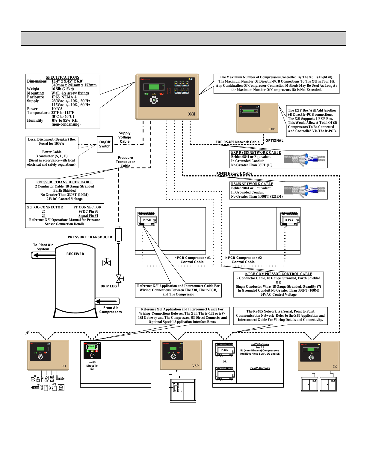
SECTION 5 — X8I SYSTEM OVERVIEW
It is recommended that installation and commissioning be carried out by an authorized and trained product supplier.
Ingersoll Rand Automation
Model X8I
Dimensions 13.4” x 9.45” x 6.0”
340mm x 241mm x 152mm
Weight 16.5lb (7.5kg)
Mounting Wall, 4 x screw fixings
Enclosure IP65, NEMA 4
Supply 230Vac +/- 10%, 50 Hz
115Vac +/- 10%, 60 Hz
Power 100VA
Temperature 32°F to 115°F
(0°C to 46°C)
Humidity 0% to 95% RH
(non-condensing)
electrical and safety regulations).
X8I X05 CONNECTOR PT CONNECTOR
SPECIFICATIONS
Local Disconnect (Breaker) Box
Fused for 100VA
Power Cable
3 conductor (N, L, E)
(Sized in accordance with local
PRESSURE TRANSDUCER CABLE
2 Conductor Cable, 18 Gauge Stranded
Reference X8I Operations Manual for Pressure
Earth Shielded
No Greater Than 330FT (100M)
24VDC Control Voltage
25 +VDC Pin #3
26 Signal Pin #1
Sensor Connection Details
On/Off
Switch
Supply
Voltage
Cable
Pressure
Transducer
Cable
ir-PCB ir-PCB
The Maximum Number of Compressors Controlled By The X8I Is Eight (8).
The Maximum Number Of Direct ir-PCB Connections To The X8I is Four (4).
Any Combination Of Compressor Connection Methods May Be Used As Long As
the Maximum Number Of Compressors (8) Is Not Exceeded.
The EXP Box Will Add Another
(4) Direct ir-PCB connections.
The X8I Supports 1 EXP Box.
This Would Allow A Total Of (8)
Compressors To Be Connected
And Controlled Via The ir-PCB.
EXP RS485 Network Cable
EXP RS485 NETWORK CABLE
Belden 9841 or Equivalent
In Grounded Conduit
No Greater Than 33FT (10)
OPTIONAL
RS485 Network Cable
RS485 NETWORK CABLE
Belden 9841 or Equivalent
In Grounded Conduit
No Greater Than 4000FT (1219M)
To Plant Air
System
PRESSURE TRANSDUCER
RECEIVER
DRIP LEG
From Air
Compressors
Ingersoll
Rand
102 psi
ir-485
Direct To
S3
Ir-PCB Compressor #1
Control Cable
Reference X8I Application and Interconnect Guide For
Wiring Connections Between The X8I, The ir-PCB,
Reference X8I Application and Interconnect Guide For
Wiring Connections Between The X8I, The ir-485 or irV-
485 Gateway and The Compressor, S3 Direct Connects, and
and The Compressor
Optional Special Application Interface Boxes
From VSD Pressure
Transducer
To VSD Pressure
Transducer Input
1
D
2
LE
D
LE
ir-
PCB
ir-485
irV-485
Ir-PCB Compressor #2
Control Cable
ir-PCB COMPRESSOR CONTROL CABLE
7 Conductor Cable, 18 Gauge, Stranded, Earth Shielded
Single Conductor Wire, 18 Gauge Stranded, Quantity (7)
In Grounded Conduit No Greater Than 330FT (100M)
The RS485 Network is a Serial, Point to Point
Communication Network Refer to the X8I Application and
Interconnect Guide For Wiring Details and Connectivity.
ir-485 Gateway
For All
IR (Non- Nirva na ) Comp res so rs
IntelliSys “Red Eye”, SG and SE
OR
irV-485 Gateway
For All
Nirvana Compressors
20HP (15KW) and Above
OR
24VAC Control Voltage
34
6
Page 7
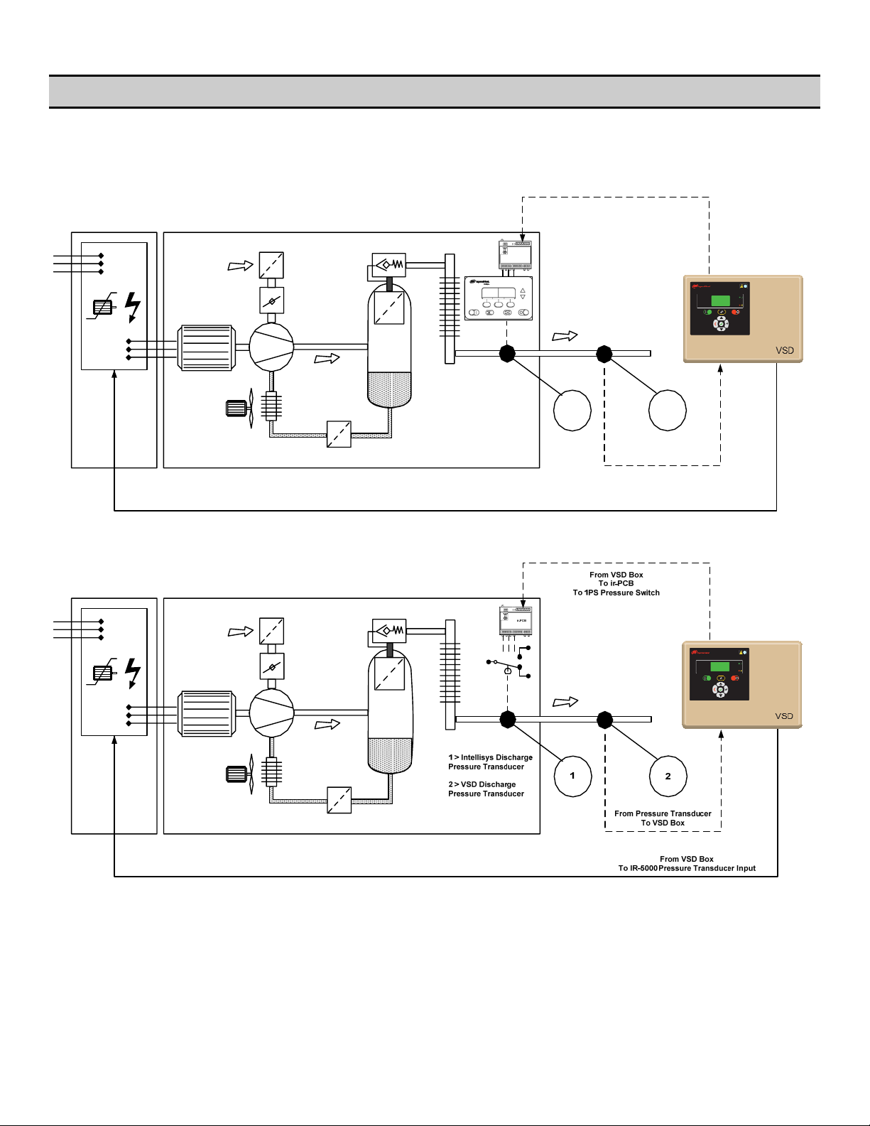
SECTION 6 — VSD OVERVIEW
It is recommended that installation and commissioning be carried out by an authorized and trained product supplier.
Ingersoll Rand Automation
VSD Box
From VSD Box
To ir-PCB
LED 1
LED 2
ir-PCB
1 > Intellisys Discharge
Pressure Transducer
2 > VSD Discharge
Pressure Transducer
To Intellisys Controller
1
From Pressure Transducer
2
To VSD Box
From VSD Box
To IR-5000 Pressure Transducer Input
7
Page 8

SECTION 7 — ASSISTANCE
Contacting Technical Support Services or Service Bulletins listed on the IR ServiceNet can provide further assistance if there
are other questions or concerns during Installation and Start-up. Also, additional Application and Compressor Interconnect
Guides will be posted and available on the IR ServiceNet as they are developed and created.
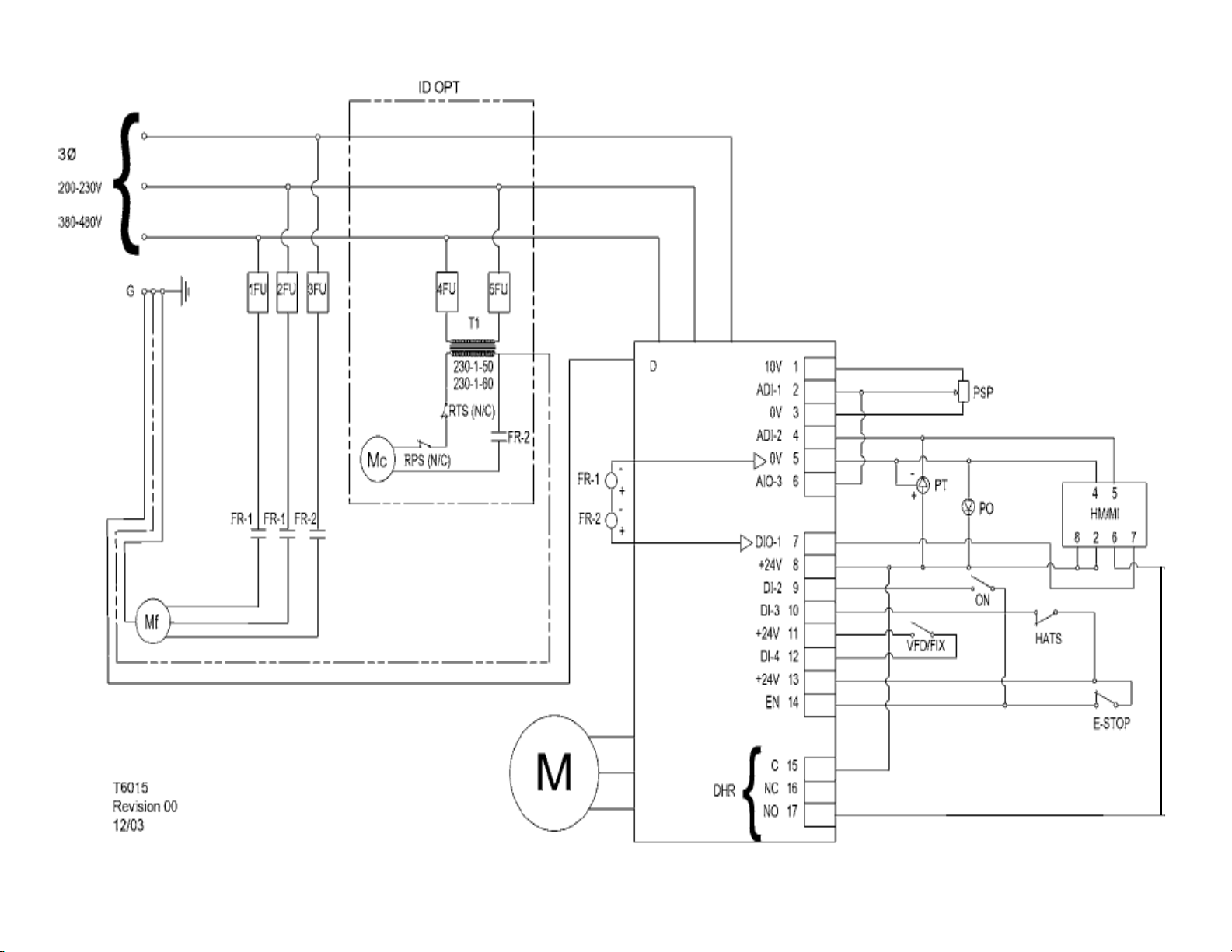
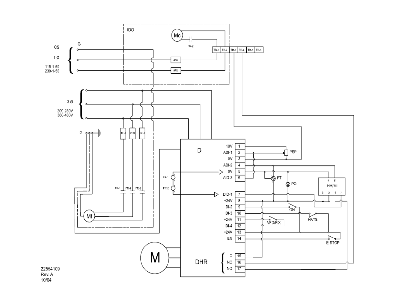
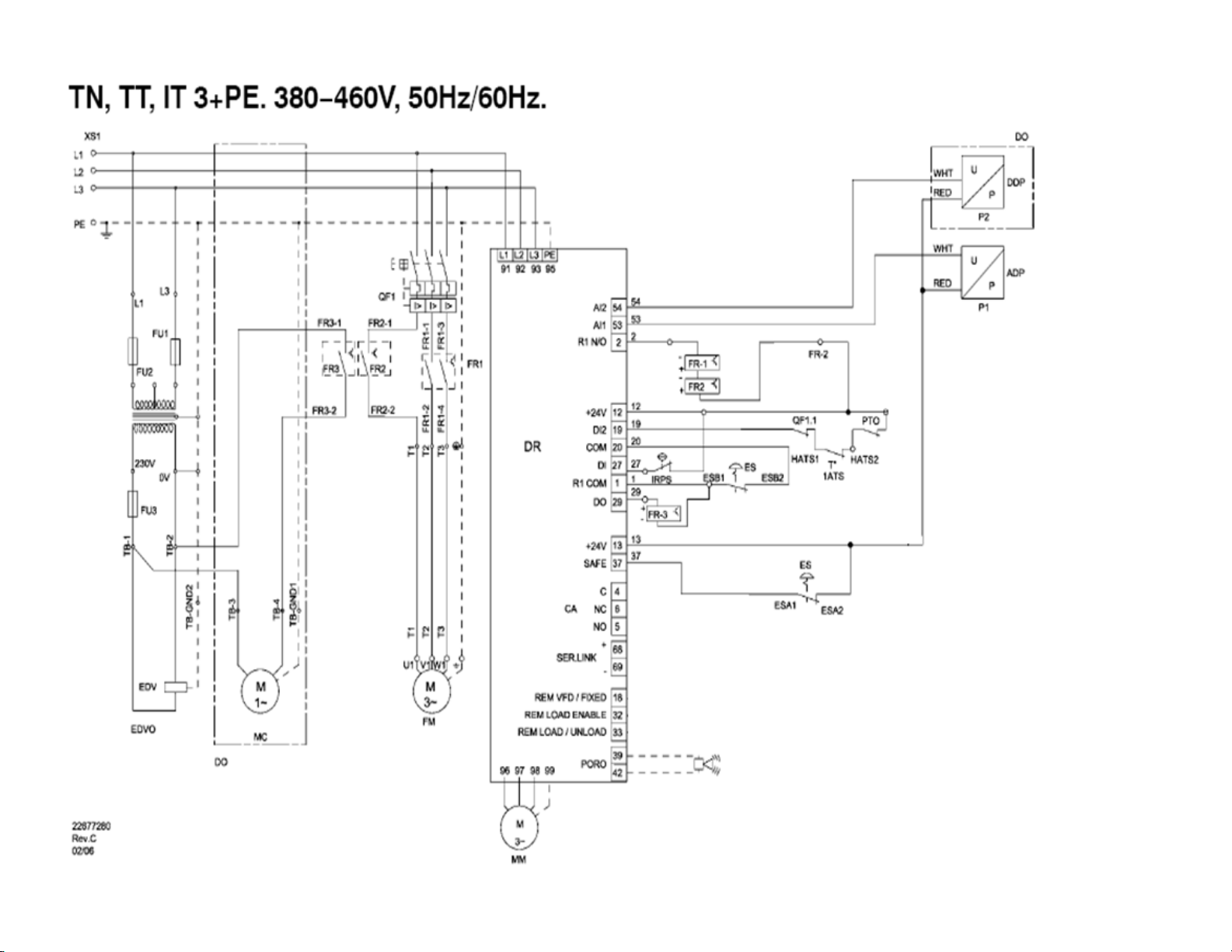
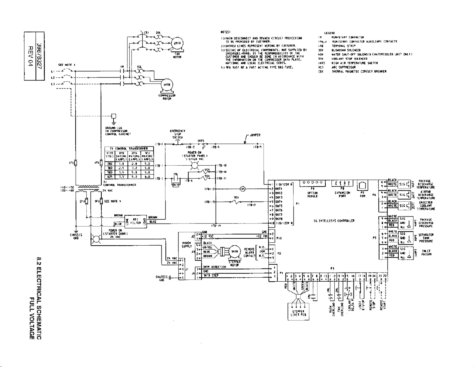
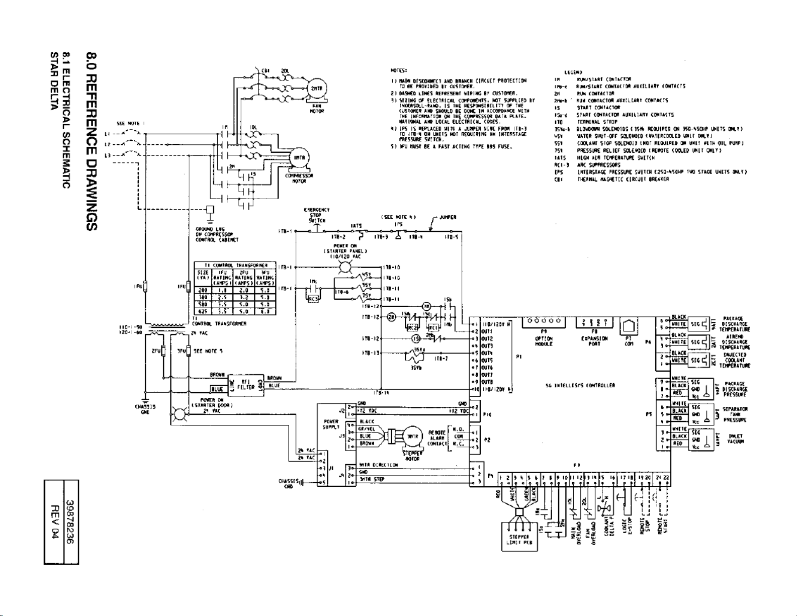
SECTION 8 — COMPRESSOR INTERCONNECT DRAWINGS
The following Appendix’s contain reference drawings designed to assist with the connection of the X – Series Automation
System to Ingersoll Rand Air Compressors as well as Non-Ingersoll Rand Air Compressors. These drawings are for
Guidance Only; connections may differ with date, model, type, variant, special, custom or concession builds. This
information is intended to be used in conjunction with the compressor’s original control circuit diagram.
INTELLISYS CONTROLLER E-PROM ROMMENDATION REFERENCE LIST
Minimum Recommended E-prom Levels - IntelliSys Controllers
IntelliSys - Firs t Generation
SSR 50 - 450HP
Sierra 100 - 200HP
Recip
IntelliSys - Second Generation
SSR 50 - 450 (1 & 2 Stage)
SSR 75 - 350kW (ESA)
Sierra 125-400HP
Recip
Redeye SE
2.4 1.75
2.7 1.23
1.62 1.93
SG SGN
1.5 1.45
1.5 SGNe
1.35 2.4
1.28 1.2
IntelliSys - Second Edition
SSR 15 - 100HP (DSA)
SSR - UP (Pegasus)
SSR 22 - 150kW (ESA)
Sierra 50 - 100HP
IntelliSys - Nirvana
Nirvana CC 100 - 200HP
IntelliSys - Nirvana
Nirvana CC 50 - 300HP
Nirvana OF 50 - 200HP
1.3
INTELLISYS CONTROLLER INTERCONNECT RECOMMENDATION
When using the X8I Automation System, the ir-485 and irV-485 Gateway is the “recommended and preferred” method when
interfacing and connecting to the FG (redeye), SG, SGN and SGNe, SE IntelliSys controlled compressors and Nirvana 1530KW (20-40HP) Compressors. See Appendix A for interconnect drawings for these applications
When using the X4I Automation System, the ir-PCB is the only method when interfacing and connecting to the FG (redeye),
SG, SGN and SGNe, SE IntelliSys controlled compressors and Nirvana 15-30KW (20-40HP) Compressors. See Appendix B for
interconnect drawings for these applications
8
Page 9

APPENDIX A
ir-485, irV-485, and RS485 DIRECT TO INGERSOLL RAND
INTELLISYS AND NIRVANA 15-30KW (20-40HP)
COMPRESSOR INTERCONNECT DRAWINGS
IR-485, IRV-485, AND RS485 DIRECT to Ingersoll Rand
Intellisys and Nirvana 15-30kw (20-40hp) ................... A1
irV-485 Interconnect To Ingersoll Rand Intellisys SGN /
SGNe Controlled Compressors ..................................... A2
ir-485 Interconnect To Ingersoll Rand Intellisys SG
Controlled Compressors .............................................. A3
ir-485 Interconnect To Ingersoll Rand Intellisys SE
Controlled Compressors .............................................. A4
ir-485 Interconnect To Ingersoll Rand Intellisys Redeye
Controlled Compressors .............................................. A5
RS485 Direct Interconnect To Ingersoll Rand Intellisys S3
Controlled Compressors .............................................. A6
irV-485 Interconnect To Ingersoll Rand Nirvana 15-30kw
(20-40HP) .................................................................... A7
9
Page 10

ir-485, irV-485, and RS485 DIRECT To Ingersoll Rand
Intellisys and Nirvana 15-30KW (20-40HP) Compressors
All Intellsys and Nirvana 15-30KW (20-40HP) Compressors
All compressors must have Automatic Start / Stop
ir-485
ir-485
ir-485
irV-485
No Modbus Functionality in Controller
Redeye Controller
Operates in irbus mode
Sequence Control Set To “ON”
Remote Start / Stop Set To “OFF”
SG Recip Controller
No Modbus Functionality in Controller
Operates in irbus mode
Sequence Control Set To “ON”
Remote Start / Stop Set To “OFF”
`SE Controller
No Modbus Functionality in Controller
Operates in irbus mode
Sequence Control Set To “ON”
Remote Start / Stop Set To “OFF”
SG Controller
Modbus Functionality in Controller
Set Modbus To ON
Set Modbus Address To Unique
Modbus Address
1-8 For X8I 1-12 For x12I
Sequence Control Set To “ON”
Remote Start / Stop Set To “OFF”
irV-485
RS485 Direct
From X8I or X12I
Automation
System
Modbus Functionality in Controller
SGN Controller
Set Modbus To ON
Set Modbus Address To Unique
Modbus Address
1-8 For X8I 1-12 For x12I
Sequence Control Set To “ON”
Remote Start / Stop Set To “OFF”
S3 Controller
Modbus Functionality in Controller
Set Modbus To ON
Set Modbus Address To Unique
Modbus Address
1-8 For X8I 1-12 For x12I
Remote Control Set To “ON”
Remote Start / Stop Set To “OFF”
Appendix A - Page A1
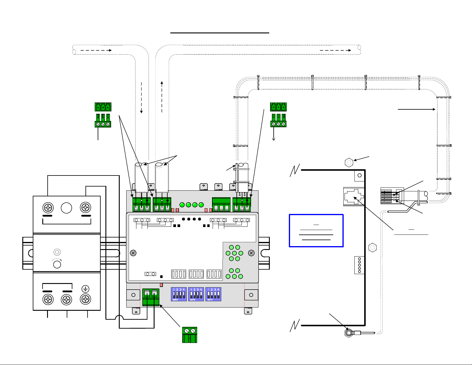
Page 11
From Previous X8I or X12I
Automation Network
Component
irV-485 To INTELLISYS SGN / SGNe
RS485 RS485
X04
And
X02
X05
To Next
X8I or X12I Automation
Network Component
RJ11 Modbus Cable
Supplied With The
irV-485 Gateway
Modify As Shown By
Removing The RJ11 Plug.
0VDC
-V
NC
OUTPUT
idec
DC ON
V.ADJ
INPUT
100/240 VAC 0.17A
50/60HZ
L
L N G
From Compressor
110 / 230VAC
24VDC 0.3A
7.5
POWER SUPPLY
PS5R-A24
N
+24VDC
+V
WOUTPUT
SHIELD
L1L2
L1L2
GROUND
SHIELD
SGN/SGNe
Mounting Bolt
GROUND
WIRE
2121
P10
P8
P7
Phoenix 6Pin
CONNECTOR
6
5
43
21
L2
2
1
L1
SGN / SGNe
Phoenix 6Pin
COM PORT
On Right Side
As Viewed From
The Back
n
e
e
r
c
s
X01
+24VDC
0VDC
2
L
X05
123 123
1
L
c
d
/
c
c
d
a
/
V
c
4
a
2
V
+
0
1 2
1212
X04
ir485
irV-485
1
#
D
E
L
ON
OFF
6
7
8
#
#
#
D
D
D
E
E
2
#
D
E
L
SW1 SW2
E
3
L
L
L
#
D
E
L
2
341
+24
0
V
V
DC
DC
12
SGN / SGNe
As Viewed From
The Back Side Of
The Controller
4
#
D
E
L
SW3
9
n
e
e
r
c
s
101
1
2
L
X03
2
1
123 123
1
L
X02
irbus /
Modbus
9
#
D
E
5
L
#
D
E
L
6
785
Place Ground
Wire Lug Behind
SGN/SGNe
Mounting Bolt
Appendix A - Page A2
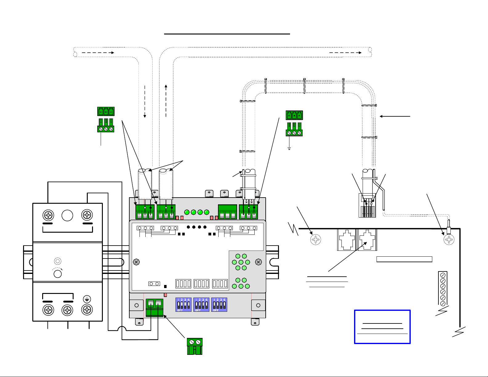
Page 12
From Previous X8I or X12I
Automation Network
Component
ir-485 To INTELLISYS SG
RS485 RS485
To Next
X8I or X12I Automation
Network Component
0VDC
-V
OUTPUT
idec
DC ON
V.ADJ
INPUT
100/240 VAC 0.17A
L
NC
24VDC 0.3A
7.5
POWER SUPPLY
PS5R-A24
50/60HZ
N
+24VDC
+V
WOUTPUT
SHIELD
X04
And
X02
X05
L1L2
L1L2
RJ11 Modbus Cable
Supplied With The
irV-485 Gateway
GROUND
SHIELD
SG
Mounting Bolt
GROUND
WIRE
21
P10
n
e
e
r
c
s
X01
2
L
X05
123 123
1
L
c
d
/
c
c
d
a
/
V
c
4
a
2
V
+
0
1 2
X04
ir485
1
#
D
E
L
ON
OFF
1212
6
#
D
E
2
3
L
#
#
D
D
E
E
L
L
ir-485
SW1 SW2
2
341
4
#
D
E
L
SW3
9
n
e
e
r
c
s
101
1
2
L
X03
2
1
123 123
1
L
8
9
7
#
#
#
D
D
D
E
E
E
5
L
L
L
#
D
E
L
6
785
X02
irbus /
Modbus
12
SG
As Viewed From
The Back Side Of
The Controller
P7
P9
P8
SG
RJ11 COM PORT
On Right Side
As Viewed From
RJ11
The Back
L2 (4)
43
2
1
CONNECTOR
6
5
4
3
2
1
L1 (2)
L N G
From Compressor
110 / 230VAC
+24VDC
0VDC
+24
DC
Place Ground
Wire Lug Behind
0
V
V
DC
SG Mounting Bolt
Appendix A - Page A3
Page 13
From Previous X8I or X12I
Automation Network
Component
ir-485 To INTELLISYS SE
RS485 RS485
To Next
X8I or X12I Automation
Network Component
0VDC
-V
OUTPUT
idec
DC ON
V.ADJ
INPUT
100/240 VAC 0.17A
L
NC
24VDC 0.3A
7.5
POWER SUPPLY
PS5R-A24
50/60HZ
N
SHIELD
+24VDC
+V
WOUTPUT
X04
And
X02
X05
L1L2
L1L2
RJ11 Modbus Cable
Supplied With The
irV-485 Gateway
GROUND
SHIELD
SG
Mounting Bolt
GROUND
WIRE
n
e
e
r
c
s
X01
2
L
X05
123 123
1
L
c
d
/
c
c
d
a
/
V
c
4
a
2
V
+
0
1 2
X04
ir485
1
#
D
E
L
ON
OFF
1212
6
#
D
E
2
3
L
#
#
D
D
E
E
L
L
ir-485
SW1 SW2
2
341
RJ11
CONNECTOR
6
5
4
12
7
9
8
#
#
#
D
D
D
E
E
E
5
L
L
L
#
D
E
L
123 123
SE
4
1
n
2
#
e
L
e
D
r
E
c
L
s
X03
X02
L
irbus /
Modbus
As Viewed From
The Back Side Of
The Controller
J8
3
2
1
RJ11 COM PORT
On Right Side
As Viewed From
The Back
SW3
2
1
1
101
6
785
9
J11
L2 (4)
L1 (2)
SE
L N G
From Compressor
110 / 230VAC
+24VDC
0VDC
+24
DC
Place Ground
Wire Lug Behind
0
V
V
DC
SE Mounting Bolt
Appendix A - Page A4
Page 14
From Previous X8I or X12I
Automation Network
ir-485 To INTELLISYS REDEYE
Component
RS485 RS485
To Next
X8I or X12I Automation
Network Component
0VDC
-V
NC
OUTPUT 24VDC 0.3A
idec
DC ON
V.ADJ
INPUT
100/240 VAC 0.17A
L
7.5
POWER SUPPLY
PS5R-A24
50/60HZ
N
+V
W
SHIELD
+24VDC
OUTPUT
X04
And
X05
L1L2
X02
L1L2
RJ11 Modbus Cable
Supplied With The
irV-485 Gateway
GROUND
SHIELD
GROUND
L2 (4)
L1 (2)
WIRE
Redeye
Starter Interface
Board
Mounting Bolt
X02
irbus /
Modbus
12
Test Port
1212
123 123
1
n
2
e
L
e
r
c
s
X05
X04
L
ir485
6
7
8
9
#
#
#
#
D
D
D
D
E
E
E
2
3
#
#
D
D
E
E
L
L
E
L
5
L
L
L
#
D
E
L
123 123
4
1
n
2
#
L
e
L
e
D
r
E
c
L
s
X03
ir-485
RJ11
CONNECTOR
J2
1
6235
4
Sequencer Port
Place Ground
Wire Lug Behind
Starter Interface
Board Mounting
Screw
J3
c
X01
d
/
c
a
V
4
2
+
1 2
c
d
/
c
a
V
0
1
#
D
E
L
ON
OFF
SW1 SW2
2
341
SW3
2
1
1
101
9
6
785
REDEYE STARTER
INTERFACE BOARD
RJ11 COM PORT
On Top Center
BTS
As Viewed Facing Board
L N G
From Compressor
110 / 230VAC
+24VDC
0VDC
+24
DC
0
V
V
DC
REDEYE STARTER
INTERFACE BOARD
As Viewed Facing Board
Appendix A - Page A5
Page 15
X01
X01
X04
X04
X02
X02 X03
X09
X07 X08
GND
Vcc
TxD RxD
1212
SHIELD
X03
X06 X05
X05X06X07 X08
IntelliSys S3
As Viewed From
The Back Side Of
The Controller
RS485 RS485
From Previous X8I or X12I
Automation Network
Component
RS485 To INTELLISYS S3
To Next
X8I or X12I Automation
Network Component
Appendix A - Page A6
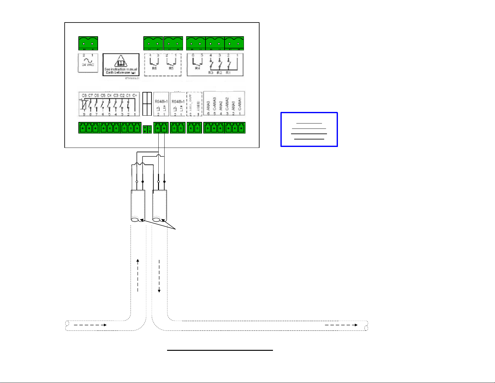
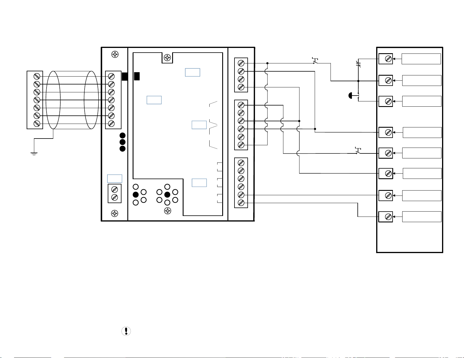
Page 16

From Previous X8I or X12I
Automation Network
irV-485 To NIRVANA 15-30KW (20-40HP)
Component
RS485 RS485
To Next
X8I or X12I Automation
Network Component
0VDC
-V
NC
OUTPUT 24VDC 0.3A
idec
DC ON
V.ADJ
INPUT
100/240 VAC 0.17A
L
7.5
POWER SUPPLY
PS5R-A24
50/60HZ
N
+V
W
SHIELD
+24VDC
OUTPUT
X04
And
X05
L1L2
X02
L1L2
RJ11 Modbus Cable
Supplied With The
irV-485 Gateway
NIRVANA 15-30KW
(20-40HP)
SHIELD
GROUND
CONTROL BOARD
As Viewed Facing Board
GROUND
WIRE
n
e
e
r
c
s
X01
2
L
X05
123 123
1
L
c
d
/
c
c
d
a
/
V
c
4
a
2
V
+
0
1 2
X04
ir485
1
#
D
E
L
ON
OFF
1212
3
2
#
#
D
D
E
E
L
L
ir-485
SW1 SW2
2
341
4
#
D
E
L
SW3
9
n
e
e
r
c
s
101
1
2
L
X03
2
1
123 123
1
L
6
7
8
9
#
#
#
#
D
D
D
D
E
E
E
E
L
5
L
L
L
#
D
E
L
6
785
X02
irbus /
Modbus
12
NIRVANA
15-30KW
(20-40HP)
COM PORT
On Right
Side As
Viewed
From The
2 1
68 6961
L1
Back
68 6961
L2
L N G
From Compressor
110 / 230VAC
+24VDC
0VDC
+24
V
DC
DC
0
V
Phoenix 3Pin
CONNECTOR
Place Ground Wire Lug
Behind
NIRVANA 15-30KW
(20-40HP) Mounting Bolt
Appendix A - Page A7
Page 17

APPENDIX B
ir-PCB TO INGERSOLL RAND INTELLISYS CONTROLLED
COMPRESSOR INTERCONNECT DRAWINGS
ir-PCB Interconnect Requirements For Ingersoll Rand
Unigy & Nirvana 15-30KW (20-40HP) Compressors .......B1
Unigy 1 1of2.................................................................B2
Unigy 1 2of2.................................................................B3
Unigy 2/3 1of2 ............................................................. B4
Unigy 2/3 2of2 ............................................................. B5
Nirvana 15-30KW (20-40HP) 1of2..................................B6
Nirvana 15-30KW (20-40HP) 2of2..................................B7
ir-PCB Interconnect Requirements For Ingersoll Rand
Intellisys Redeye Controlled Compressors ....................B8
SSR Redeye 1of3 ...........................................................B9
SSR Redeye FV 2of3 ....................................................B10
SSR Redeye SD 3of3 ....................................................B11
ir-PCB Interconnect Requirements For Ingersoll Rand
Intellisys SE Controlled Compressors .......................... B12
SE UP 1of2 ..................................................................B13
SE UP 2of2 ..................................................................B14
SE ESA 1of2 ................................................................B15
SE ESA 2of2 ................................................................B16
SE DSA 1of2................................................................B17
SE DSA 2of2................................................................B18
ir-PCB Interconnect Requirements For Ingersoll Rand
Intellisys SG Controlled Compressors..........................B19
SG SSR 1of2 ................................................................ B20
SG SSR 2of2 ................................................................ B21
SG Sierra 1of2.............................................................B22
SG Sierra 2of2.............................................................B23
ir-PCB Interconnect Requirements For Ingersoll Rand
Intellisys SGN / SGNe Controlled Compressors ........B24
Nirvana SGN/SGNe 1of3 .............................................. B25
Nirvana SGN/SGNe 2of3 .............................................. B26
Nirvana SGN/SGNe 3of3 .............................................. B27
SI1 Interface to Redeye, SE, SG Controllers.................. B28
ir-PCB Interconnect Requirements For Ingersoll Rand
Intellisys S3 ................................................................B29
Intellisys S3 1of2 ........................................................B30
Intellisys S3 2of2 ........................................................B31
ir-PCB Interconnect Requirements For Ingersoll Rand CMC
Sierra 1of2.................................................................. B32
ir-PCB Interconnect Requirements For Ingersoll Rand CMC
Sierra 2of2.................................................................. B33
17
Page 18

ir-PCB Interconnect To Ingersoll Rand
Unigy & Nirvana 20-40 HP Compressors
FOR UNIGY COMPRESSORS:
All Unigy Phase 1 compressors “MUST” be converted to Phase 2 or higher. Contact Technical Support Services for the
CCN's required for this conversion.
FOR NIRVANA 20-40HP COMPRESSORS:
When using the X8I Automation System, the ir-485 and irV-485 Gateway is the “recommended and preferred” method
when interfacing and connecting to the FG (redeye), SG, SGN and SGNe, SE IntelliSys controlled compressors and
Nirvana 15-30KW (20-40HP) Compressors. See Appendix A for interconnect drawings for these applications
When using the X4I Automation System, the ir-PCB is the only method when interfacing and connecting to the FG
(redeye), SG, SGN and SGNe, SE IntelliSys controlled compressors and Nirvana 15-30KW (20-40HP) Compressors. See
Appendix B for interconnect drawings for these applications
Remote Control “MUST” be set to “ON”.
Remote Start / Stop must be set to “OFF”.
Check the Nirvana Software revision level. It “MUST” be updated to Version 1.10 or greater. Contact Technical Support
Services to acquire the update.
DRAWING NOTES FOR UNIGY PHASE 1 MACHINES:
Note: All Unigy Phase 1 compressors “MUST” be converted to Phase 2 or higher. Contact Technical Support Services
for the CCN's required for this conversion. The Drawing “Unigy Phase 1 1of2” is a representation for “AFTER” the
conversion is completed.
Note: The Unigy Target Pressure “MUST” be set equal to the “midpoint” of the X - Series Automation pressure control
band.
DRAWING NOTES FOR UNIGY PHASE 2/3 MACHINES:
Note: The Unigy Target Pressure “MUST” be set equal to the “midpoint” of the X - Series Automation pressure control
band.
DRAWING NOTES FOR NIRVANA 20-40HP MACHINES:
Note: Remote Control “MUST” be set to on.
Note: The Nirvana Target Pressure “MUST” be set equal to the “midpoint” of the X - Series Automation pressure
control band.
Appendix B Page B1
Page 19
Unigy Phase 1
X - SERIES AUTOMATION
COMPRESSOR #1
X01 TERMINAL
V1
1
2
3
4
5
6
C05
V
1
2
3
4
5
6
1
2
V
SEQ CONT
LOAD UNL
GND
C03
D11
D12
+20V
LED 5 V
LED 2 LOAD
LED 1 SEQ
LED 4
READY
LED 3
RUN
C01
Load Enable
Load/Unload
C02
C04
IR-PCB
+VDC
VFD/fixed
NO
OUT
NC
NO
IN
NC
ALARM
RUN
READY
D13
+24VDC
SA1
HATS
10
13
E-STOP
14
EN
C
12
DI-4
C
VFD/FIX
11
9
5
17
+24VDC
DI-2
0V
NO
Guidance only; connections may differ with date, model, type, variant, special, custom or concession builds.
This information is intended to be used in conjunction with the compressor’s original control circuit diagram.
Unigy 1
7.5 - 15 HP
5.5 – 11 kW
Appendix B Page B2
Page 20
Unigy Phase 1
Appendix B Page B3
Page 21
Unigy Phase 2/3
X - SERIES AUTOMATION
COMPRESSOR #1
X01 TERMINAL
V1
1
2
3
4
5
6
C05
V
1
SEQ CONT
LOAD UNL
2
GND
3
D11
4
D12
5
+20V
6
LED 5 V
LED 2 LOAD
LED 1 SEQ
READY
1
2
V
LED 4
C03
RUN
LED 3
C01
Load Enable
Load/Unload
C02
C04
IR-PCB
+VDC
VFD/fixed
NO
OUT
NC
NO
IN
NC
ALARM
RUN
READY
D13
+24VDC
SA1
10
HATS
13
E-STOP
14
EN
C
12
DI-4
C
VFD/FIX
11
9
5
17
+24VDC
DI-2
0V
NO
Guidance only; connections may differ with date, model, type, variant, special, custom or concession builds.
This information is intended to be used in conjunction with the compressor’s original control circuit diagram.
Unigy
7.5 - 15 HP
5.5 – 11 kW
Appendix B Page B4
Page 22
Unigy Phase 2/3
Appendix B Page B5
Page 23
Nirvana 15 – 30KW
(20 – 40HP)
X - SERIES AUTOMATION
COMPRESSOR #1
X01 TERMINAL
V1
1
2
3
4
5
6
C05
V
1
SEQ CONT
LOAD UNL
2
GND
3
D11
4
D12
5
+20V
6
LED 5 V
LED 2 LOAD
LED 1 SEQ
READY
1
2
12
+24VDC
+VDC
VFD/fixed
V
C01
Load Enable
Load/Unload
C03
NO
OUT
18
32
33
Remote
VFD / FIXED
Remote
LOAD ENABLE
Remote
LOAD / UNLOAD
C
IN
NC
NO
C
C02
NC
SAFE
C
COM
LED 4
RUN
LED 3
C04
ALARM
RUN
READY
37
4
20
IR-PCB
6
NC
Alternate Connection Metthod For
READY Input If Alarm Contacts Are
Being Used
READY
Guidance only; connections may differ with date, model, type, variant, special, custom or concession builds.
This information is intended to be used in conjunction with the compressor’s original control circuit diagram.
Nirvana
20 - 40 HP
15 – 30 kW
37
SAFE
Appendix B Page B6
Page 24
Nirvana 15 - 30KW
(20-40HP)
Appendix B Page B7
Page 25

ir-PCB Interconnect To Ingersoll Rand
First Generation IntelliSys “Redeye” Controlled Compressors
FOR REDEYE INTELLISYS CONTROLLED MACHINES:
When using the X8I Automation System, the ir-485 and irV-485 Gateway is the “recommended and preferred” method
when interfacing and connecting to the FG (redeye), SG, SGN and SGNe, SE IntelliSys controlled compressors and
Nirvana 15-30KW (20-40HP) Compressors. See Appendix A for interconnect drawings for these applications
When using the X4I Automation System, the ir-PCB is the only method when interfacing and connecting to the FG
(redeye), SG, SGN and SGNe, SE IntelliSys controlled compressors and Nirvana 15-30KW (20-40HP) Compressors. See
Appendix B for interconnect drawings for these applications
The ‘MASTER CONTROL’ setting of the Intellisys controller must be set to ‘ON’
The 'SEQUENCER' setting of the Intellisys controller must be set to 'ON'.
Remote Start / Stop must be set to “OFF”.
Auto Restart must be turned 'ON’ to allow the machines to stop in Auto restart when unloaded by the X - Series
Automation.
The Intellisys must be run in the Online/Offline regulation mode. Do not use Modulation or ACS.
Check the Intellisys software revision level. Always update to the latest revision prior to operation.
FOR DSA REDEYE CONTROLLERS, the 'SEQUENCER Option’ must be purchased. installed and then turned on.
CCN: 39225099
FOR ESA REDEYE INTELLISYS CONTROLLERS, the SI1 interface (CCN: 42425710) must be used to allow the Redeye to
be controlled by the X - Series Automation
FOR SIERRA REDEYE INTELLISYS CONTROLLERS, the SI1 interface (CCN: 42425710) must be used to allow the Redeye
Controller to be sequenced/controlled by the X - Series Automation
DRAWING NOTES FOR REDEYE INTELLISYS CONTROLLED MACHINES:
Note: For Star Delta starter wiring the X - Series Automation Run signal should be connected directly to the 1M coil.
Note: For Full voltage wiring the 1S (1Sb) interlock will not be used. The X - Series Automation Run signal can be
connected directly to the Intellisys BTS1-28 terminal.
Appendix B Page B8
Page 26

X - SERIES AUTOMATION
COMPRESSOR #1
X01 TERMINAL
V1
1
2
3
4
5
6
C05
V
1
SEQ CONT
LOAD UNL
2
GND
3
D11
4
D12
5
+20V
6
LED 5 VFD
LED 2 LOAD
LED 1 SEQ
READY
1
2
SSR Redeye
Analog Barrier Board
BTS311
+VDC
VFD/fixed
V
C03
LED 4
RUN
LED 3
C01
Load Enable
Load/Unload
C02
C04
IR-PCB
NO
OUT
NC
NO
IN
NC
ALARM
RUN
READY
C
C
0VAC
110VAC
E-STOP
1M
HATS
12
16
18
BTS1-
1
BTS1-
34
Remote Load/Unload
(was Remote Start)
Remote Load Enable
(was Remote Stop)
Alternate Connection Metthod For
READY Input If Alarm Contacts Are
Being Used
READY
Guidance only; connections may differ with date, model, type, variant, special, custom or concession builds.
This information is intended to be used in conjunction with the compressor’s original control circuit diagram.
110VAC
E-STOP
HATS
BTS2-
1
2
3
Starter Interface Board
BTS2
34
Appendix B Page B9
Page 27
SSR Redeye FV
Appendix B Page B10
Page 28
SSR Redeye SD
Appendix B Page B11
Page 29

ir-PCB Interconnect To Ingersoll Rand
Second Edition Intellisys “SE” Controlled Compressors
FOR ALL SE INTELLISYS CONTROLLED MACHINES:
When using the X8I Automation System, the ir-485 and irV-485 Gateway is the “recommended and preferred” method
when interfacing and connecting to the FG (redeye), SG, SGN and SGNe, SE IntelliSys controlled compressors and
Nirvana 15-30KW (20-40HP) Compressors. See Appendix A for interconnect drawings for these applications
When using the X4I Automation System, the ir-PCB is the only method when interfacing and connecting to the FG
(redeye), SG, SGN and SGNe, SE IntelliSys controlled compressors and Nirvana 15-30KW (20-40HP) Compressors. See
Appendix B for interconnect drawings for these applications
The 'SEQUENCER' setting of the Intellisys controller must be set to 'ON'.
Remote Start / Stop must be set to “OFF”.
Auto Restart must be turned 'ON’ to allow the machines to stop in Auto restart when unloaded by the X - Series
Automation.
The Intellisys must be run in the Online/Offline regulation mode. Do not use Modulation or ACS.
Check the Intellisys software revision level. Always update to the latest revision prior to operation.
FOR UP SE INTELLISYS CONTROLLERS
Minimum Software Version 1.11
CCN: 39217047 (w/o PORO)
CCN: 39217039 (w PORO)
When installing the Sequence Option to enable Remote Load/Unload, the Remote Start/Stop input terminals
are now used for the Remote Load inputs. Remote Start Stop will no longer be functional. The SI1 interface (CCN: 42425710)
can be used in place of the Sequence Option to allow the SE controlled machines to function with both Remote Load Unload
and Remote Start Stop.
Software Version 1.20 and Greater
The 'CONTACT SEQUENCE' setting of the Intellisys controller must be set to 'ON'.
DRAWING NOTES FOR UP SE INTELLISYS CONTROLLED MACHINES:
Note: For Star Delta starter wiring the X - Series Automation Run signal should be connected directly to the 1M coil.
Note: For Full voltage wiring the 1S (1Sb) interlock will not be used. The X - Series Automation Run signal can be
connected directly to the Intellisys J5-1 terminal.
Note: For Pegasus machines wiring may be factory installed connecting the Intellisys Alarm Relay J5-9, J5-10 and J5-11
to a terminal strip but unused. Remove any factory installed wiring from the Intellisys Alarm Relay contacts and connect
the X - Series Automation Interface board wiring directly to the Intellisys Alarm Relay terminals J5-9 and J5-10.
FOR ESA SE INTELLISYS CONTROLLERS
Minimum Software Version 1.40
CCN: 39217047 (w/o PORO)
CCN: 39217039 (w PORO)
When installing the Sequence Option to enable Remote Load/Unload, the Remote Start Stop input terminals
are now used for the Remote Load inputs. Remote Start Stop will no longer be functional. The SI1 interface (CCN: 42425710)
can be used in place of the Sequence Option to allow the SE controlled machines to function with both Remote Load Unload
and Remote Start Stop.
DRAWING NOTES FOR ESA SE INTELLISYS CONTROLLED MACHINES:
Note: For Star Delta starter wiring the X - Series Automation Run signal should be connected directly to the 1M coil.
Note: For Full voltage wiring the 1S (1Sb) interlock will not be used. The X - Series Automation Run signal can be
connected directly to the Intellisys J5-1 terminal.
FOR DSA SE INTELLISYS CONTROLLERS
CCN: 22179238
When installing the Sequence Option to enable Remote Load/Unload, the Remote Start Stop input terminals
are now used for the Remote Load inputs. Remote Start Stop will no longer be functional. The SI1 interface (CCN: 42425710)
can be used in place of the Sequence Option to allow the SE controlled machines to function with both Remote Load Unload
and Remote Start Stop.
DRAWING NOTES FOR DSA SE INTELLISYS CONTROLLED MACHINES:
Note: For Star Delta starter wiring the X - Series Automation Run signal should be connected directly to the 1M coil.
Note: For Full Voltage wiring, the 1S (1Sb) interlock will not be used. The X - Series Automation Run signal can be
connected directly to the Intellisys terminal 42.
,
, the 'SEQUENCER Option’ must be purchased. installed and then turned on.
, the 'SEQUENCER Option’ must be purchased. installed and then turned on.
FOR SIERRA SE INTELLISYS CONTROLLERS
be sequenced/controlled by the X - Series Automation
, the SI1 interface (CCN: 42425710) must be used to allow the SE Controller to
Appendix B Page B12
Page 30
SE UP
X - SERIES AUTOMATION
COMPRESSOR #1
X01 TERMINAL
V1
1
2
3
4
5
6
C05
V
1
SEQ CONT
LOAD UNL
2
GND
3
D11
4
D12
5
+20V
6
LED 5 VFD
LED 2 LOAD
LED 1 SEQ
READY
1
2
J1
+VDC
VFD/fixed
V
C03
LED 4
RUN
LED 3
C01
Load Enable
Load/Unload
C02
C04
IR-PCB
NO
OUT
NC
NO
IN
NC
ALARM
RUN
READY
C
C
0VAC
110VAC
E-STOP
1M
11
12
13
14
J5
1
J5
7
J5
9
10
11
Remote Load/Unload
(was Remote Start)
Remote Enable
(was Remote Stop)
Intellisys SE
UP Series
Alternate Connection Metthod For
READY Input If Alarm Contacts Are
Being Used
READY
Guidance only; connections may differ with date, model, type, variant, special, custom or concession builds.
This information is intended to be used in conjunction with the compressor’s original control circuit diagram.
110VAC
E-STOP
J5
7
Appendix B Page B13
Page 31

SE UP
Appendix B Page B14
Page 32

SE ESA
X - SERIES AUTOMATION
COMPRESSOR #1
X01 TERMINAL
V1
1
2
3
4
5
6
C05
V
1
SEQ CONT
LOAD UNL
2
GND
3
D11
4
D12
5
+20V
6
LED 5 VFD
LED 2 LOAD
LED 1 SEQ
READY
1
2
V
LED 4
C03
LED 3
RUN
C01
Load Enable
Load/Unload
C02
C04
IR-PCB
+VDC
VFD/fixed
NO
OUT
NC
NO
IN
NC
ALARM
RUN
READY
J1
11
12
13
14
C
C
J5
1
J5
7
J5
9
10
11
110VAC
0VAC
MCB2
HAT
1M
E-STOP
Remote Load/Unload
(was Remote Start)
Remote Enable
(was Remote Stop)
Intellisys SE
ESA Series
Alternate Connection Metthod For
READY Input If Alarm Contacts Are
Being Used
READY
Guidance only; connections may differ with date, model, type, variant, special, custom or concession builds.
This information is intended to be used in conjunction with the compressor’s original control circuit diagram.
110VAC
E-STOP
J5
7
Appendix B Page B15
Page 33

SE ESA
Appendix B Page B16
Page 34

SE DSA
X - SERIES AUTOMATION
COMPRESSOR #1
X01 TERMINAL
V1
1
2
3
4
5
6
C05
V
1
SEQ CONT
LOAD UNL
2
GND
3
D11
4
D12
5
+20V
6
LED 5 VFD
LED 2 LOAD
LED 1 SEQ
READY
1
2
J1
+VDC
VFD/fixed
V
C03
LED 4
RUN
LED 3
C01
Load Enable
Load/Unload
C02
C04
IR-PCB
NO
OUT
NC
NO
IN
NC
ALARM
RUN
READY
C
C
0VAC
110VAC
E-STOP
1M
1ATS
6
5
4
3
J5
42
J5
36
J5
34
33
32
Remote Load/Unload
(was Remote Start)
Remote Enable
(was Remote Stop)
Intellisys SE
DSA Contact
Cooled
Alternate Connection Metthod For
READY Input If Alarm Contacts Are
Being Used
READY
Guidance only; connections may differ with date, model, type, variant, special, custom or concession builds.
This information is intended to be used in conjunction with the compressor’s original control circuit diagram.
110VAC
E-STOP
J5
38
Appendix B Page B17
Page 35

SE DSA
Appendix B Page B18
Page 36

ir-PCB Interconnect To Ingersoll Rand
Second Generation IntelliSys “SG” Controlled Compressors
FOR SG INTELLISYS CONTROLLED MACHINES:
When using the X8I Automation System, the ir-485 and irV-485 Gateway is the “recommended and preferred” method
when interfacing and connecting to the FG (redeye), SG, SGN and SGNe, SE IntelliSys controlled compressors and
Nirvana 15-30KW (20-40HP) Compressors. See Appendix A for interconnect drawings for these applications
When using the X4I Automation System, the ir-PCB is the only method when interfacing and connecting to the FG
(redeye), SG, SGN and SGNe, SE IntelliSys controlled compressors and Nirvana 15-30KW (20-40HP) Compressors. See
Appendix B for interconnect drawings for these applications
The 'SEQUENCER' setting of the Intellisys controller must be set to 'ON'.
Remote Start / Stop must be set to “OFF”.
Auto Restart must be turned 'ON’ to allow the machines to stop in Auto restart when unloaded by the X - Series
Automation.
The Intellisys must be run in the Online/Offline regulation mode. Do not use Modulation or ACS.
Check the Intellisys software revision level. Always update to the latest revision prior to operation.
FOR SIERRA SG INTELLISYS CONTROLLERS, the SI1 interface (CCN: 42425710) can be used as an alternative to allow
the SG Controller to be sequenced/controlled by the X - Series Automation
DRAWING NOTES FOR SG INTELLISYS CONTROLLED MACHINES:
Note: For Star Delta starter wiring the X - Series Automation Run signal should be connected directly to the 1M coil.
Note: For Full Voltage wiring, the 1S (1Sb) interlock will not be used. The X - Series Automation Run signal can be
connected directly to the Intellisys P1-2 terminal.
Appendix B Page B19
Page 37

SG SSR
X - SERIES AUTOMATION
COMPRESSOR #1
X01 TERMINAL
V1
1
2
3
4
5
6
C05
V
1
SEQ CONT
LOAD UNL
2
GND
3
D11
4
D12
5
+20V
6
LED 5 VFD
LED 2 LOAD
LED 1 SEQ
READY
1
2
P3
+VDC
VFD/fixed
V
C03
LED 4
RUN
LED 3
C01
Load Enable
Load/Unload
C02
C04
IR-PCB
NO
OUT
NC
NO
IN
NC
ALARM
RUN
READY
C
C
1Sb
0VAC
110VAC
1M
1ATS
E-STOP
25
26
27
28
P1
2
P1
1
P2
3
2
1
Remote Load Enable
Remote Load/Unload
Intellisys SG
Alternate Connection Metthod For
READY Input If Alarm Contacts Are
Being Used
READY
Guidance only; connections may differ with date, model, type, variant, special, custom or concession builds.
This information is intended to be used in conjunction with the compressor’s original control circuit diagram.
110VAC
E-STOP
1ATS
P!
1
Appendix B Page B20
Page 38

SG SSR
Appendix B Page B21
Page 39

SG Sierra
X - SERIES AUTOMATION
COMPRESSOR #1
X01 TERMINAL
V1
1
2
3
4
5
6
C05
V
1
SEQ CONT
LOAD UNL
2
GND
3
D11
4
D12
5
+20V
6
LED 5 VFD
LED 2 LOAD
LED 1 SEQ
READY
1
2
P3
+VDC
VFD/fixed
V
C03
LED 4
RUN
LED 3
C01
Load Enable
Load/Unload
C02
C04
IR-PCB
NO
OUT
NC
NO
IN
NC
ALARM
RUN
READY
C
C
1Sb
0VAC
110VAC
1M
1ATS
E-STOP
25
26
27
28
P1
2
P1
1
P2
3
2
1
Remote Load Enable
Remote Load/Unload
Intellisys SG
Alternate Connection Metthod For
READY Input If Alarm Contacts Are
Being Used
READY
Guidance only; connections may differ with date, model, type, variant, special, custom or concession builds.
This information is intended to be used in conjunction with the compressor’s original control circuit diagram.
110VAC
E-STOP
1ATS
P!
1
Appendix B Page B22
Page 40

SG Sierra
Appendix B Page B23
Page 41

ir-PCB Interconnect To Ingersoll Rand
Nirvana IntelliSys “SGN / SGNe” Controlled Compressors
FOR SGN/SGNE INTELLISYS CONTROLLED MACHINES:
When using the X8I Automation System, the ir-485 and irV-485 Gateway is the “recommended and preferred” method
when interfacing and connecting to the FG (redeye), SG, SGN and SGNe, SE IntelliSys controlled compressors and
Nirvana 15-30KW (20-40HP) Compressors. See Appendix A for interconnect drawings for these applications
When using the X4I Automation System, the ir-PCB is the only method when interfacing and connecting to the FG
(redeye), SG, SGN and SGNe, SE IntelliSys controlled compressors and Nirvana 15-30KW (20-40HP) Compressors. See
Appendix B for interconnect drawings for these applications
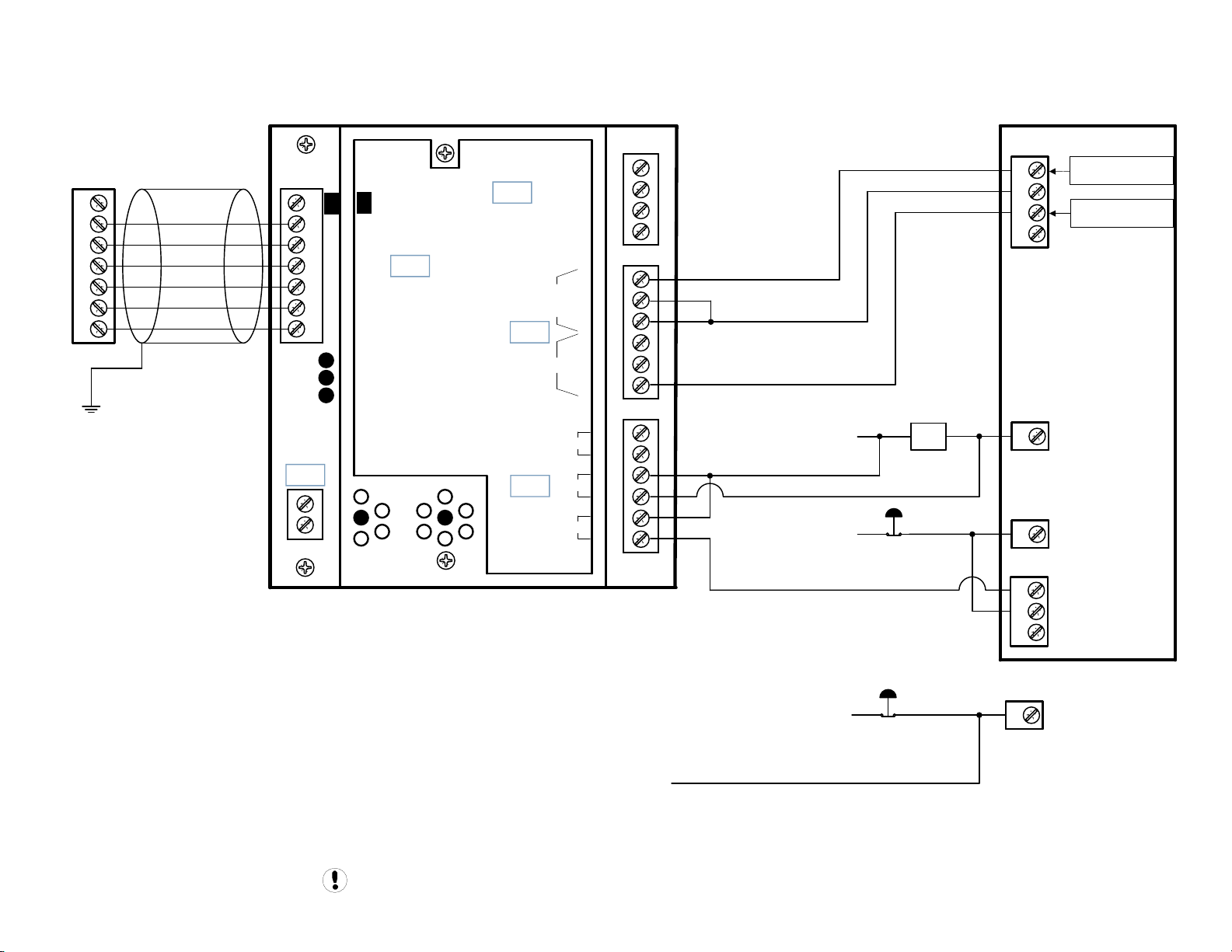
The SI1 interface (CCN: 42425710) must be used to allow the SGN/SGNe Controller to be sequenced/controlled by the X Series Automation
The 'SEQUENCER' setting of the Intellisys controller must be set to 'ON'.
Remote Start / Stop must be set to “OFF”.
Auto Restart must be turned 'ON’ to allow the machines to stop in Auto restart when unloaded by the X - Series
Automation.
The Intellisys must be run in the Online/Offline regulation mode. Do not use Modulation or ACS.
Check the Intellisys software revision level. Always update to the latest revision prior to operation.
DRAWING NOTES FOR NIRVANA MACHINES:
Note: The Nirvana Target Pressure “MUST” be set equal to the Midpoint of the X - Series Automation pressure control
band.
Refer to the X - Series Automation Overview Drawing for the X - Series Automation Compressor 2 through 4 X01 to IRPCB terminal connections
Appendix B Page B24
Page 42

Nirvana SGN/SGNe
Sequence Interface 1
X - SERIES AUTOMATION
COMPRESSOR #1
X01 TERMINAL
V1
1
2
3
4
5
6
C05
V
1
SEQ CONT
LOAD UNL
2
GND
3
D11
4
D12
5
+20V
6
LED 5 VFD
LED 2 LOAD
LED 1 SEQ
READY
1
2
1
Remote Load / Unload
+VDC
VFD/fixed
V
C03
LED 4
LED 3
RUN
Alternate Connection Metthod For
READY Input If Alarm Contacts Are
Being Used
C01
Load Enable
Load/Unload
C02
C04
IR-PCB
NO
OUT
NC
NO
IN
NC
ALARM
RUN
READY
C
C
H
N
110 VAC
Supply
HATS
P!
1
110VAC
110VAC
E-STOP
E-STOP
1ATS
2
3
Run
4
Remote Load Enable
5
Neutral
6
Neutral
7
Hot
SGN/
SGNe
P1
1
SGN/
SGNe
P2
3
2
1
Intellisys Controller
COM
COM
READY
Guidance only; connections may differ with date, model, type, variant, special, custom or concession builds.
This information is intended to be used in conjunction with the compressor’s original control circuit diagram.
Appendix B Page B25
Page 43

Nirvana SGN/SGNe
Appendix B Page B26
Page 44

Nirvana SGN/SGNe
Appendix B Page B27
Page 45

SI1 Interface to Redeye, SE, SG Controllers
Sequence Interface 1
X - SERIES AUTOMATION
COMPRESSOR #1
X01 TERMINAL
V1
1
2
3
4
5
6
V
V
1
SEQ CONT
LOAD UNL
2
GND
3
4
5
6
C05
1
2
Alternate Connection Metthod For
READY Input If Alarm Contacts Are
Being Used
C03
D11
D12
+20V
LED 5 VFD
LED 2 LOAD
LED 1 SEQ
LED 4
READY
RUN
LED 3
C01
IR-PCB
110VAC
+VDC
VFD/fixed
Load Enable
Load/Unload
NO
OUT
IN
ALARM
READY
E-STOP
NC
NO
NC
RUN
C02
C04
C
C
1ATS
Redeye
BTS134 36
110VAC
SE
DSA
J5
E-STOP
SE
ESA/UP
J5
7
N
110 VAC
Supply
HATS
SG
P1
1
1
Remote Load / Unload
2
3
Run
4
Remote Load Enable
5
Neutral
6
Neutral
7
Hot
H
Redeye
BTS1-
34 36
Redeye
BTS2-
1
2
3
SE
DSA
J5
SE
DSA
J5
34
33
32
Intellisys Controller
SE
ESA/UP
J5
7
SE
ESA/UP
J5
9
10
11
COM
COM
SG
P1
1
SG
P2
3
2
1
READY
Guidance only; connections may differ with date, model, type, variant, special, custom or concession builds.
This information is intended to be used in conjunction with the compressor’s original control circuit diagram.
Appendix B Page B28
Page 46

a
n
d
o
l
l
e
r
o
I
c
t
o
n
n
t
e
r
P
C
B
i
r
-
I
n
c
e
T
n
g
s
R
t
s
o
s
o
r
r
i
e
s
-Se
t
he
X
y
e
a
b
d
d
l
o
.
.
n
t
i
o
per
a
o
s
p
r
C
o
l
l
e
o
n
t
r
s
s
y
i
n
e
t
a
p
u
o
con
t
o
s
i
on mode
d
a
t
3
/
S
C
f
”
w
O
H
1
C
:
S
E
I
N
H
e
t
I
e
n
l
l
i
n
A
E
a
m
r
e
e
lways
:
S
c
gul
i
h
t
h
t
he
f
f
l
.
l
I
N
y
s
L
t
’
O
i
S3
9
3
E
A
M
D
C”
o
“
R
o
F
“
F
O
l
o
t
a
o
l
e
l
i
n
n
l
eve
n
i
o
s
C
A
M
0
9
2
9
5
1
0
t
e
l
l
i
T
N
'
s
t
b
ned
n
a
LLI
3
:
C
S
L
O
R
t
t
e
i
ng
set
e
N
O
'
t
he
i
n
r
r
e
e
v
S
Y
S
9
4
2
0
3
:
N
C
I
n
O
C
S
Y
I
S
L
L
S3
t
R
k
E
T
I
N
L
O
R
T
N
O
C
E
T
O
M
E
s
t
a
a
r
n
y
I
E
R
r
t
/
must
t
.
s
mu
t
e
n
S
a
e
l
a
S
l
l
i
O
F
y
B
y
op mu
b
e
s
t
b
ys
s
N
I
R
I
C
R
a
s
e
t
u
r
e
r
u
s
o
f
t
w
E
T
N
C
I
R
–
e
t
S
t
e
s
a
t
i
o
t
e
l
l
i
s
e
t
h
T
O
N
1
Rel
R
1
R
L
L
A
R
O
F
R
'
e
h
T
e
o
R
m
t
o
u
A
u
A
m
t
o
I
n
e
h
T
h
C
e
c
G
N
I
W
A
R
D
:
t
e
o
N
:
t
e
o
N
d
l
l
e
r
mu
t
r
o
i
A
n
t
op
s
.
o
D
t
o
t
he
l
e
a
m
t
b
set
e
s
est
u
t
o
r
s
e
u
t
o
n
t
e
v
s
r
e
t
e
'
.
N
O
'
o
t
n
e
u
a
i
n
r
t
h
w
l
a
u
t
n
i
o
d
o
M
i
o
s
r
i
p
o
n
r
Appendix B Page B29
Page 47

Intellisys S3
X - SERIES AUTOMATION
COMPRESSOR #1
X01 TERMINAL
V1
1
2
3
4
5
6
C05
V
1
SEQ CONT
LOAD UNL
2
GND
3
D11
4
D12
5
+20V
6
LED 5 VFD
LED 2 LOAD
LED 1 SEQ
READY
1
2
X04
+VDC
VFD/fixed
V
C03
LED 4
RUN
LED 3
C01
Load Enable
Load/Unload
C02
C04
IR-PCB
NO
OUT
NC
NO
IN
NC
ALARM
RUN
READY
C
C
KM2
Contact
0VAC
R1
Contact
KM1
1
7
Remote Load Enable
8
Remote Load/Unload
X03
2
X02
R1
Coil
Guidance only; connections may differ with date, model, type, variant, special, custom or concession builds.
This information is intended to be used in conjunction with the compressor’s original control circuit diagram.
110VAC
3
4
Intellisys S3
Appendix B Page B30
Page 48

Intellisys S3
Appendix B Page B31
Page 49

CMC Sierra
X4I / X8I / X12I
COMPRESSOR #1
X01 TERMINAL
V1
1
2
3
4
5
6
C05
V
1
SEQ CONT
LOAD UNL
2
GND
3
D11
4
D12
5
+20V
6
LED 5 VFD
LED 2 LOAD
LED 1 SEQ
READY
1
2
Terminal
Strip
2TB
+VDC
VFD/fixed
V
C03
LED 4
LED 3
RUN
C01
Load Enable
Load/Unload
C02
C04
NO
OUT
NC
NO
IN
NC
ALARM
RUN
READY
C
C
1Sb
1TB12
1M
1
2TB
5
2TB
6
1TB
5
Remote Load Enable
Remote Load/Unload
BCM
+24VDC
IR-PCB
The CMC Controller must be updated with Release Version 1.42 or greater.
The file can be found on the ServiceNet. Select Centrifugal, then select CMC Files, then select V320.
The Executable file is 22458368.exe
Guidance only; connections may differ with date, model, typ e, variant, special, custom or concession builds.
This information is intended to be used in conjunction with the compressor’s original control circuit diagram.
CMC
Appendix B Page B32
Page 50

Appendix B Page B33
Page 51

APPENDIX C
ir-PCB TO INGERSOLL RAND PRESSURE SWITCH CONTROLLED
COMPRESSOR INTERCONNECT DRAWINGS
ir-PCB Interconnect Requirements For Ingersoll Rand
Pressure Switch Controlled Compressors ..................... C1
SSR UP5 11-22 SD 1of2 ................................................ C2
SSR UP5 11-22 SD 2of2 ................................................ C3
SSR UP5 22-37 SD 1of2 ................................................ C4
SSR UP5 22-37 SD 2of2 ................................................ C5
SSR UP6 15-30 FV 1of2 ................................................ C6
SSR UP6 15-30 FV 2of2 ................................................ C7
SSR UP6 15-30 SD 1of2 ................................................ C8
SSR UP6 15-30 SD 2of2 ................................................ C9
SSR UP6 40-50 FV 1of2 .............................................. C10
SSR UP6 40-50 FV 2of2 .............................................. C11
SSR UP6 40-50 SD 1of2 .............................................. C12
SSR UP6 40-50 SD 2of2 .............................................. C13
UP6 5-15 FV 1PH 60Hz 1of2 ...................................... C14
UP6 5-15 FV 1PH 60Hz 2of2 ...................................... C15
UP6 5-15 FV 3PH 60Hz 1of2 ...................................... C16
UP6 5-15 FV 3PH 60Hz 2of2 ...................................... C17
UP6 5-15 SD 3PH 60Hz 1of2 ...................................... C18
UP6 5-15 SD 3PH 60Hz 2of2 ...................................... C19
UP6 5-15 FV 3PH 50Hz 1of2 ...................................... C20
UP6 5-15 FV 3PH 50Hz 2of2 ...................................... C21
UP6 5-15 SD 3PH 50Hz 1of2 ...................................... C22
UP6 5-15 SD 3PH 50Hz 2of2 ...................................... C23
SSR M15-22c 20-30HP XF EP HP HXP
50-60Hz 1of2 ............................................................ C24
SSR M15-22c 20-30HP XF EP HP HXP
50-60Hz 2of2 ............................................................ C25
M37-50 1of2.............................................................. C26
M37-50 2of2.............................................................. C27
EP 20-30 ESP FV 1of2 ................................................. C28
EP 20-30 ESP FV 2of2 ................................................. C29
EP 20-30 ESP SD 1of2................................................. C30
EP 20-30 ESP SD 2of2................................................. C31
ir-PCB Interconnect Requirements For Ingersoll Rand
Small Reciprocating Air Compressors ........................C32
UP6RE 7.5–15 175, UP6RX 7.5–15 175 1of3 ...............C33
UP6RE 7.5–15 175, UP6RX 7.5–15 175 2of3 ...............C34
UP6RE 7.5–15 175, UP6RX 7.5–15 175 3of3 ...............C35
Models 2340, 2475, 2545, 7100,
15T & 3000 10f3 ........................................................C36
Models 2340, 2475, 2545, 7100,
15T & 3000 20f3 ........................................................C37
Models 2340, 2475, 2545, 7100,
15T & 3000 30f3 ........................................................C38
Excessive Pressure Shutdown Switch Example Before
Installation ................................................................C39
Excessive Pressure Shutdown Switch Example After
Installation ................................................................C40
51
Page 52

ir-PCB Interconnect To Ingersoll Rand
Pressure Switch Controlled Compressors
FOR ALL COMPRESSORS:
Compressors to be connected must have automatic Start / Stop capability .
DRAWING NOTES FOR PRESSURE SWITCH CONTROLLER MACHINES:
Ensure each compressor is equipped with independent Excessive Pressure Shutdown Switch. An increase in pressure
differential across air treatment equipment can result in excess compressor discharge pressure. See Appendix A, Page
70 and 71 for application drawings. In most applications, the model and type of pressure switch supplied with the
compressor can be used as the Excessive Pressure Shutdown Switch
is not readily available, any pressure switch can be utilized as long as it equals or exceeds the specifications of the
pressure switch found on the compressor.
Set the Excessive Pressure Shutdown Switch to “OPEN” 5 PSI less than the maximum discharge pressure
recommended by the compressor manufacturer.
. If this is specific model/type of pressure switch
Appendix C Page C1
Page 53

SSR UP5 11-22 SD
X - SERIES AUTOMATION
COMPRESSOR #1
X01 TERMINAL
V1
1
2
3
4
5
6
C05
V
1
2
3
4
5
6
1
2
V
SEQ CONT
LOAD UNL
GND
C03
D11
D12
+20V
LED 5 VFD
LED 2 LOAD
LED 1 SEQ
LED 4
READY
E-STOP
110VAC
+VDC
VFD/fixed
C01
Load Enable
Load/Unload
NO
OUT
C
C02
LED 3
RUN
C04
NC
NO
IN
NC
ALARM
RUN
READY
C
MOL
Contact
SS
P
KM1 Relay
Contact
HATR
Contact
KM1
Restart TD
Relay
Contact
To TM2 Relay
To KM1 Contact
To KM2 Contact
0 VAC
IR-PCB
Guidance only; connections may differ with date, model, type, variant, special, custom or concession builds.
This information is intended to be used in conjunction with the compressor’s original control circuit diagram.
UnLoad
1PS
To Avoid Potential Wiring Issues, Always Break / Make ir-PCB
Wire Connections At The Pressure Switch Or Cut / Splice The
Actual Pressure Switch Wires
Wire Per The Above Schematic
Load
Appendix C Page C2
Page 54

SSR UP5 11-22 SD
Appendix C Page C3
Page 55

X - SERIES AUTOMATION
COMPRESSOR #1
X01 TERMINAL
V1
1
2
3
4
5
6
V
1
SEQ CONT
LOAD UNL
2
GND
3
D11
4
D12
5
+20V
6
LED 5 VFD
LED 2 LOAD
LED 1 SEQ
READY
SSR UP5 22-37 SD
E-STOP
110VAC
+VDC
VFD/fixed
V
C03
LED 4
LED 3
RUN
C01
Load Enable
Load/Unload
C02
NO
OUT
NC
NO
IN
NC
ALARM
C
C
MOL
Contact
MMS
Contact
KM1
Relay
Contact
TM3
Relay
Contact
SS
P
KM1 Relay
Contact
HATR
Contact
KM1
Restart TD
Relay
Contact
To TM2 Relay
To KM1 Contact
To KM2 Contact
0 VAC
C05
C04
RUN
1
2
IR-PCB
Guidance only; connections may differ with date, model, type, variant, special, custom or concession builds.
This information is intended to be used in conjunction with the compressor’s original control circuit diagram.
READY
UnLoad
1PS
To Avoid Potential Wiring Issues, Always Break / Make ir-PCB
Wire Connections At The Pressure Switch Or Cut / Splice The
Actual Pressure Switch Wires
Wire Per The Above Schematic
Load
Appendix C Page C4
Page 56

SSR UP5 22-37 SD
Appendix C Page C5
Page 57

SSR UP6 15-30 FV
X - SERIES AUTOMATION
COMPRESSOR #1
X01 TERMINAL
V1
1
2
3
4
5
6
C05
V
1
SEQ CONT
LOAD UNL
2
GND
3
D11
4
D12
5
+20V
6
LED 5 VFD
LED 2 LOAD
LED 1 SEQ
READY
1
2
E-STOP
110VAC
+VDC
VFD/fixed
V
C03
LED 4
LED 3
RUN
C01
Load Enable
Load/Unload
C02
C04
NO
OUT
NC
NO
IN
NC
ALARM
RUN
READY
C
C
ON OFFCOL
1PS
HATR
Contact
M
Restart TD
Relay
Contact
To TR Relay
To M Contact
To 1SV
To 3SV
0 VAC
IR-PCB
Guidance only; connections may differ with date, model, type, variant, special, custom or concession builds.
This information is intended to be used in conjunction with the compressor’s original control circuit diagram.
UnLoad
1PS
To Avoid Potential Wiring Issues, Always Break / Make ir-PCB
Wire Connections At The Pressure Switch Or Cut / Splice The
Actual Pressure Switch Wires
Wire Per The Above Schematic
Load
Appendix C Page C6
Page 58

SSR UP6 15-30 FV
Appendix C Page C7
Page 59

SSR UP6 15-30 SD
X - SERIES AUTOMATION
COMPRESSOR #1
X01 TERMINAL
V1
1
2
3
4
5
6
C05
V
1
SEQ CONT
LOAD UNL
2
GND
3
D11
4
D12
5
+20V
6
LED 5 VFD
LED 2 LOAD
LED 1 SEQ
READY
1
2
E-STOP
110VAC
+VDC
VFD/fixed
V
C03
LED 4
LED 3
RUN
C01
Load Enable
Load/Unload
C02
C04
NO
OUT
NC
NO
IN
NC
ALARM
RUN
READY
C
C
ON OFFOL
1PS
1M
Contact
HATR
Contact
1M
Restart TD
Relay
Contact
To TR Relay
To 1M Contact
To 2M Contact
0 VAC
IR-PCB
Guidance only; connections may differ with date, model, type, variant, special, custom or concession builds.
This information is intended to be used in conjunction with the compressor’s original control circuit diagram.
UnLoad
1PS
To Avoid Potential Wiring Issues, Always Break / Make ir-PCB
Wire Connections At The Pressure Switch Or Cut / Splice The
Actual Pressure Switch Wires
Wire Per The Above Schematic
Load
Appendix C Page C8
Page 60

SSR UP6 15-30 SD
Appendix C Page C9
Page 61

SSR UP6 40-50 FV
1M
Relay
Contact
TDRI
Relay
Contact
X - SERIES AUTOMATION
COMPRESSOR #1
X01 TERMINAL
V1
1
2
3
4
5
6
C05
V
1
SEQ CONT
LOAD UNL
2
GND
3
D11
4
D12
5
+20V
6
LED 5 VFD
LED 2 LOAD
LED 1 SEQ
READY
1
2
E-STOP
110VAC
+VDC
VFD/fixed
V
C03
LED 4
LED 3
RUN
C01
Load Enable
Load/Unload
C02
C04
NO
OUT
NC
NO
IN
NC
ALARM
RUN
READY
C
C
OL
MMS
Contact
SS
ON OFF
1PS
HATR
Contact
1M
Restart TD
Relay
Contact
To TR Relay
To 1M Contact
To TDRI Contact
0 VAC
IR-PCB
Guidance only; connections may differ with date, model, type, variant, special, custom or concession builds.
This information is intended to be used in conjunction with the compressor’s original control circuit diagram.
UnLoad
1PS
To Avoid Potential Wiring Issues, Always Break / Make ir-PCB
Wire Connections At The Pressure Switch Or Cut / Splice The
Actual Pressure Switch Wires
Wire Per The Above Schematic
Load
Appendix C Page C10
Page 62

SSR UP6 40-50 FV
Appendix C Page C11
Page 63

SSR UP6 40-50 SD
1M
Relay
Contact
TDRI
Relay
Contact
X - SERIES AUTOMATION
COMPRESSOR #1
X01 TERMINAL
V1
1
2
3
4
5
6
C05
V
1
SEQ CONT
LOAD UNL
2
GND
3
D11
4
D12
5
+20V
6
LED 5 VFD
LED 2 LOAD
LED 1 SEQ
READY
1
2
E-STOP
110VAC
+VDC
VFD/fixed
V
C03
LED 4
LED 3
RUN
C01
Load Enable
Load/Unload
C02
C04
NO
OUT
NC
NO
IN
NC
ALARM
RUN
READY
C
C
OL
MMS
Contact
SS
ON OFF
1PS
1M
Contact
HATR
Contact
1M
Restart TD
Relay
Contact
To TR Relay
To 1M Contact
To 2M Contact
0 VAC
IR-PCB
Guidance only; connections may differ with date, model, type, variant, special, custom or concession builds.
This information is intended to be used in conjunction with the compressor’s original control circuit diagram.
UnLoad
1PS
To Avoid Potential Wiring Issues, Always Break / Make ir-PCB
Wire Connections At The Pressure Switch Or Cut / Splice The
Actual Pressure Switch Wires
Wire Per The Above Schematic
Load
Appendix C Page C12
Page 64

SSR UP6 40-50 SD
Appendix C Page C13
Page 65

UP6 5-15 FV 1PH 60Hz
X - SERIES AUTOMATION
COMPRESSOR #1
X01 TERMINAL
V1
1
2
3
4
5
6
C05
V
1
SEQ CONT
LOAD UNL
2
GND
3
D11
4
D12
5
+20V
6
LED 5 VFD
LED 2 LOAD
LED 1 SEQ
READY
1
2
To 1M Contact
+VDC
VFD/fixed
V
C03
LED 4
LED 3
RUN
C01
Load Enable
Load/Unload
C02
C04
IR-PCB
NO
OUT
NC
NO
IN
NC
ALARM
RUN
READY
C
C
110VAC
E-STOP
HATS
STOL
CR
Contact
PS
M
To CR Relay
To HM
To EDV
To M
0 VAC
UnLoad
Guidance only; connections may differ with date, model, type, variant, special, custom or concession builds.
This information is intended to be used in conjunction with the compressor’s original control circuit diagram.
1PS
To Avoid Potential Wiring Issues, Always Break / Make ir-PCB
Wire Connections At The Pressure Switch Or Cut / Splice The
Actual Pressure Switch Wires
Wire Per The Above Schematic
Load
Appendix C Page C14
Page 66

UP6 5-15 FV 1PH 60Hz
Appendix C Page C15
Page 67

UP6 5-15 FV 3PH 60Hz
X - SERIES AUTOMATION
COMPRESSOR #1
X01 TERMINAL
V1
1
2
3
4
5
6
C05
V
1
SEQ CONT
LOAD UNL
2
GND
3
D11
4
D12
5
+20V
6
LED 5 VFD
LED 2 LOAD
LED 1 SEQ
READY
1
2
To 1M Contact
+VDC
VFD/fixed
V
C03
LED 4
LED 3
RUN
C01
Load Enable
Load/Unload
C02
C04
IR-PCB
NO
OUT
NC
NO
IN
NC
ALARM
RUN
READY
C
C
110VAC
E-STOP
HATS
STOL
CR
Contact
PS
M
To CR Relay
To HM
To EDV
To M
0 VAC
UnLoad
Guidance only; connections may differ with date, model, type, variant, special, custom or concession builds.
This information is intended to be used in conjunction with the compressor’s original control circuit diagram.
1PS
To Avoid Potential Wiring Issues, Always Break / Make ir-PCB
Wire Connections At The Pressure Switch Or Cut / Splice The
Actual Pressure Switch Wires
Wire Per The Above Schematic
Load
Appendix C Page C16
Page 68

UP6 5-15 FV 3PH 60Hz
Appendix C Page C17
Page 69

UP6 5-15 SD 3PH 60Hz
X - SERIES AUTOMATION
COMPRESSOR #1
X01 TERMINAL
V1
1
2
3
4
5
6
C05
V
1
SEQ CONT
LOAD UNL
2
GND
3
D11
4
D12
5
+20V
6
LED 5 VFD
LED 2 LOAD
LED 1 SEQ
READY
1
2
To 1M Contact
+VDC
VFD/fixed
V
C03
LED 4
LED 3
RUN
C01
Load Enable
Load/Unload
C02
C04
IR-PCB
NO
OUT
NC
NO
IN
NC
ALARM
RUN
READY
C
C
110VAC
OL
E-STOP
HATS
Contact
ST
CR
Contact
PS
1M
1M
To CR Relay
To HM
To EDV
To 1M/1S/2M Contacts
To TD Relay
0 VAC
UnLoad
Guidance only; connections may differ with date, model, type, variant, special, custom or concession builds.
This information is intended to be used in conjunction with the compressor’s original control circuit diagram.
1PS
To Avoid Potential Wiring Issues, Always Break / Make ir-PCB
Wire Connections At The Pressure Switch Or Cut / Splice The
Actual Pressure Switch Wires
Wire Per The Above Schematic
Load
Appendix C Page C18
Page 70

UP6 5-15 SD 3PH 60Hz
Appendix C Page C19
Page 71

UP6 5-15 FV 3PH 50Hz
X - SERIES AUTOMATION
COMPRESSOR #1
X01 TERMINAL
V1
1
2
3
4
5
6
C05
V
1
SEQ CONT
LOAD UNL
2
GND
3
D11
4
D12
5
+20V
6
LED 5 VFD
LED 2 LOAD
LED 1 SEQ
READY
1
2
MOL
+VDC
VFD/fixed
V
C03
LED 4
RUN
LED 3
C01
Load Enable
Load/Unload
C02
C04
IR-PCB
NO
OUT
NC
NO
IN
NC
ALARM
RUN
READY
C
C
110VAC
Contact
E-STOP
HATS
ST
CR
Contact
P
KM1
Contact
To KM1 Contact
To CR Relay
To HM
To EDV
KM1/KM2/KM3 Contacts
To KM1
0 VAC
KM
UnLoad
Guidance only; connections may differ with date, model, type, variant, special, custom or concession builds.
This information is intended to be used in conjunction with the compressor’s original control circuit diagram.
1PS
To Avoid Potential Wiring Issues, Always Break / Make ir-PCB
Wire Connections At The Pressure Switch Or Cut / Splice The
Actual Pressure Switch Wires
Wire Per The Above Schematic
Load
Appendix C Page C20
Page 72

UP6 5-15 FV 3PH 50Hz
Appendix C Page C21
Page 73

UP6 5-15 SD 3PH 50Hz
X - SERIES AUTOMATION
COMPRESSOR #1
X01 TERMINAL
V1
1
2
3
4
5
6
C05
V
1
SEQ CONT
LOAD UNL
2
GND
3
D11
4
D12
5
+20V
6
LED 5 VFD
LED 2 LOAD
LED 1 SEQ
READY
1
2
MOL
+VDC
VFD/fixed
V
C03
LED 4
LED 3
RUN
C01
Load Enable
Load/Unload
C02
C04
IR-PCB
NO
OUT
NC
NO
IN
NC
ALARM
RUN
READY
C
C
110VAC
Contact
E-STOP
HATS
ST
CR
Contact
P
KM1
Contact
To KM1 Contact
To CR Relay
To HM
To EDV
KM1/KM2/KM3 Contacts
To KM1
0 VAC
KM
UnLoad
Guidance only; connections may differ with date, model, type, variant, special, custom or concession builds.
This information is intended to be used in conjunction with the compressor’s original control circuit diagram.
1PS
To Avoid Potential Wiring Issues, Always Break / Make ir-PCB
Wire Connections At The Pressure Switch Or Cut / Splice The
Actual Pressure Switch Wires
Wire Per The Above Schematic
Load
Appendix C Page C22
Page 74

UP6 5-15 SD 3PH 50Hz
Appendix C Page C23
Page 75

SSR M15-22c 20-30HP XF EP HP HXP 50-60Hz
X - SERIES AUTOMATION
COMPRESSOR #1
X01 TERMINAL
V1
1
2
3
4
5
6
110VAC
C05
MCB2
Contact
V
1
SEQ CONT
LOAD UNL
2
GND
3
D11
4
D12
5
+20V
6
LED 5 VFD
LED 2 LOAD
LED 1 SEQ
READY
1
2
MOL
HAT
V
C03
LED 4
LED 3
RUN
C01
Contact
+VDC
VFD/fixed
Load Enable
Load/Unload
NO
OUT
C02
C04
NC
NO
IN
NC
ALARM
RUN
READY
E-STOP
C
C
K3
Contact
SS
ST
(OPT)
P
TM2
Contact
ST
CR
Contact
To TM2 Relay
To KM2 Contact
KM1
To TM3 Contact
To AS Switch
K2 Contact
TM2 Contact
0 VAC
IR-PCB
Guidance only; connections may differ with date, model, type, variant, special, custom or concession builds.
This information is intended to be used in conjunction with the compressor’s original control circuit diagram.
UnLoad
1PS
To Avoid Potential Wiring Issues, Always Break / Make ir-PCB
Wire Connections At The Pressure Switch Or Cut / Splice The
Actual Pressure Switch Wires
Wire Per The Above Schematic
Load
Appendix C Page C24
Page 76

SSR M15-22c 20-30HP XF EP HP HXP 50-60Hz
Appendix C Page C25
Page 77

X - SERIES AUTOMATION
COMPRESSOR #1
X01 TERMINAL
V1
1
2
3
4
5
6
V
1
SEQ CONT
LOAD UNL
2
GND
3
D11
4
D12
5
+20V
6
LED 5 VFD
LED 2 LOAD
LED 1 SEQ
READY
M37-50
K1
Contact
48VAC
+VDC
VFD/fixed
V
C03
LED 4
LED 3
RUN
C01
Load Enable
Load/Unload
C02
NO
OUT
NC
NO
IN
NC
ALARM
P
C
C
KM1 Contact
KM1
To 2TR Contact
To 1VAC Contact
To 3OP Contact
To 2TR Relay
To KM2 Contact
0 VAC
C05
C04
RUN
1
2
IR-PCB
Guidance only; connections may differ with date, model, type, variant, special, custom or concession builds.
This information is intended to be used in conjunction with the compressor’s original control circuit diagram.
READY
KM3 Contact
UnLoad
1PS
To Avoid Potential Wiring Issues, Always Break / Make ir-PCB
Wire Connections At The Pressure Switch Or Cut / Splice The
Actual Pressure Switch Wires
Wire Per The Above Schematic
Load
Appendix C Page C26
Page 78

M37-50
Appendix C Page C27
Page 79

EP 20-30 ESP FV
110VAC
HATS
PUSH
STOP
PULL
START
To 1CR Relay
X - SERIES AUTOMATION
COMPRESSOR #1
X01 TERMINAL
V1
1
2
3
4
5
6
C05
V
SEQ CONT
1
LOAD UNL
2
GND
3
D11
4
D12
5
+20V
6
LED 5 VFD
LED 2 LOAD
LED 1 SEQ
READY
1
2
1M
CR
Contact
1M
1TD Contact
To 1TD Relay
To 1M Contact
0 VAC
CR
Contact
+VDC
VFD/fixed
V
C03
LED 4
LED 3
RUN
C01
Load Enable
Load/Unload
C02
C04
NO
OUT
NC
NO
IN
NC
ALARM
RUN
READY
1PS
C
C
Contact
IR-PCB
Guidance only; connections may differ with date, model, type, variant, speci al, cu sto m or concession builds.
This information is intended to be used in conjunction with the compressor’s original control circuit diagram.
UnLoad
1PS
To Avoid Potential Wiring Issues, Always Break / Make ir-PCB
Wire Connections At The Pressure Switch Or Cut / Splice The
Actual Pressure Switch Wires
Wire Per The Above Schematic
Load
Appendix C Page C28
Page 80

EP 20-30 ESP FV
Appendix C Page C29
Page 81

EP 20-30 ESP SD
110VAC
HATS
PUSH
STOP
PULL
START
To 1CR Relay
X - SERIES AUTOMATION
COMPRESSOR #1
X01 TERMINAL
V1
1
2
3
4
5
6
C05
V
1
SEQ CONT
LOAD UNL
2
GND
3
D11
4
D12
5
+20V
6
LED 5 VFD
LED 2 LOAD
LED 1 SEQ
READY
1
2
1M
CR
Contact
1M
1TD Contact
To 1TD Relay
To 2M Contact
0 VAC
CR
Contact
+VDC
VFD/fixed
V
C03
LED 4
LED 3
RUN
C01
Load Enable
Load/Unload
C02
C04
NO
OUT
NC
NO
IN
NC
ALARM
RUN
READY
1PS
C
C
Contact
IR-PCB
Guidance only; connections may differ with date, model, type, variant, special, custom or concession builds.
This information is intended to be used in conjunction with the compressor’s original control circuit diagram.
UnLoad
1PS
To Avoid Potential Wiring Issues, Always Break / Make ir-PCB
Wire Connections At The Pressure Switch Or Cut / Splice The
Actual Pressure Switch Wires
Wire Per The Above Schematic
Load
Appendix C Page C30
Page 82

EP 20-30 ESP SD
Appendix C Page C31
Page 83

ir-PCB Interconnect To Ingersoll Rand
Small Reciprocating Air Compressors
FOR ALL COMPRESSORS:
Compressors to be connected must have automatic Start / Stop capability .
DRAWING NOTES FOR PRESSURE SWITCH CONTROLLER MACHINES:
Ensure each compressor is equipped with independent Excessive Pressure Shutdown Switch. An increase in pressure
differential across air treatment equipment can result in excess compressor discharge pressure. See Apendix A Page
70 and 71 for application drawings. In most applications, the model and type of pressure switch supplied with the
compressor can be used as the Excessive Pressure Shutdown Switch
is not readily available, any pressure switch can be utilized as long as it equals or exceeds the specifications of the
pressure switch found on the compressor.
Set the Excessive Pressure Shutdown Switch to “OPEN” 5 PSI less than the maximum discharge pressure
recommended by the compressor manufacturer.
Note: R1 and R2 Relay - IR CCN: 39403290
Note: R1 and R2 Relay Base – IR CCN: 39125091
. If this is specific model/type of pressure switch
Appendix C Page C32
Page 84

UP6RE 7.5–15 175, UP6RX 7.5–15 175
X - SERIES AUTOMATION
COMPRESSOR #1
X01 TERMINAL
V1
1
2
3
4
5
6
C05
V
1
SEQ CONT
LOAD UNL
2
GND
3
D11
4
D12
5
+20V
6
LED 5 VFD
LED 2 LOAD
LED 1 SEQ
READY
1
2
+VDC
VFD/fixed
V
C03
LED 4
RUN
LED 3
C01
Load Enable
Load/Unload
C02
C04
IR-PCB
NO
OUT
NC
NO
IN
NC
ALARM
RUN
READY
C
C
110VAC
SS
ON OFF
To M
To ETM
LOLS
P
OL
Contact
0 VAC
M
Guidance only; connections may differ with date, model, type, variant, special, custom or concession builds.
This information is intended to be used in conjunction with the compressor’s original control circuit diagram.
UnLoad
1PS
To Avoid Potential Wiring Issues, Always Break / Make ir-PCB
Wire Connections At The Pressure Switch Or Cut / Splice The
Actual Pressure Switch Wires
Wire Per The Above Schematic
Load
Appendix C Page C33
Page 85

UP6RE 7.5–15 175, UP6RX 7.5–15 175
Appendix C Page C34
Page 86

UP6RE 7.5–15 175, UP6RX 7.5–15 175
Appendix C Page C35
Page 87

Models 2340, 2475, 2545, 7100, 15T & 3000
X - SERIES AUTOMATION
COMPRESSOR #1
X01 TERMINAL
V1
1
2
3
4
5
6
C05
V
1
SEQ CONT
LOAD UNL
2
GND
3
D11
4
D12
5
+20V
6
LED 5 VFD
LED 2 LOAD
LED 1 SEQ
READY
1
2
+VDC
VFD/fixed
V
C03
LED 4
RUN
LED 3
C01
Load Enable
Load/Unload
C02
C04
IR-PCB
NO
OUT
NC
NO
IN
NC
ALARM
RUN
READY
C
C
L1
SS
ON OFF
R1
R2
LOLS
P
To Customer Supplied
External Neutral
To Customer Supplied
External 110VAC
M
HATS
OL
Contact
To M
R2
L2
1PS
To Avoid Potential Wiring Issues, Always Break / Make ir-PCB
Wire Connections At The Pressure Switch Or Cut / Splice The
Actual Pressure Switch Wires
Guidance only; connections may differ with date, model, type, variant, special, custom or concession builds.
This information is intended to be used in conjunction with the compressor’s original control circuit diagram.
Wire Per The Above Schematic
UnLoad
R1
Load
Appendix C Page C36
Page 88

Models 2340, 2475, 2545, 7100, 15T & 3000
Appendix C Page C37
Page 89

Models 2340, 2475, 2545, 7100, 15T & 3000
Appendix C Page C38
Page 90

X - SERIES AUTOMATION
COMPRESSOR #1
X01 TERMINAL
V1
1
2
3
4
5
6
Excessive Pressure Shutdown Switch Example Before Installation
SSR UP5 11-22 SD
MOL
Contact
KM1 Relay
Contact
V
1
SEQ CONT
LOAD UNL
2
GND
3
D11
4
D12
5
+20V
6
LED 5 VFD
LED 2 LOAD
LED 1 SEQ
READY
E-STOP
110VAC
+VDC
VFD/fixed
V
C03
LED 4
LED 3
RUN
C01
Load Enable
Load/Unload
C02
NO
OUT
NC
NO
IN
NC
ALARM
C
C
SS
HATR
Contact
P
KM1
Restart TD
Relay
Contact
To TM2 Relay
To KM1 Contact
To KM2 Contact
0 VAC
C05
C04
RUN
1
2
IR-PCB
Guidance only; connections may differ with date, model, type, variant, special, custom or concession builds.
This information is intended to be used in conjunction with the compressor’s original control circuit diagram.
READY
To Avoid Potential Wiring Issues, Always Break / Make ir-PCB
Wire Connections At The Pressure Switch Or Cut / Splice The
Actual Pressure Switch Wires
1PS
Wire Per The Above Schematic
Appendix C Page C39
UnLoad
Load
Page 91

X - SERIES AUTOMATION
COMPRESSOR #1
X01 TERMINAL
V1
1
2
3
4
5
6
Excessive Pressure Shutdown Switch Example After Installation
SSR UP5 11-22 SD
MOL
Contact
KM1 Relay
Contact
V
1
SEQ CONT
LOAD UNL
2
GND
3
D11
4
D12
5
+20V
6
LED 5 VFD
LED 2 LOAD
LED 1 SEQ
READY
E-STOP
110VAC
+VDC
VFD/fixed
V
C03
LED 4
LED 3
RUN
C01
Load Enable
Load/Unload
C02
NO
OUT
NC
NO
IN
NC
ALARM
C
C
SS
HATR
Contact
P
Excessive
Shutdown
KM1
Restart TD
Relay
Contact
To TM2 Relay
To KM1 Contact
To KM2 Contact
Pressure
Switch
0 VAC
C05
C04
RUN
1
2
IR-PCB
Guidance only; connections may differ with date, model, type, variant, special, custom or concession builds.
This information is intended to be used in conjunction with the compressor’s original control circuit diagram.
READY
UnLoad
1PS
To Avoid Potential Wiring Issues, Always Break / Make ir-PCB
Wire Connections At The Pressure Switch Or Cut / Splice The
Actual Pressure Switch Wires
Wire Per The Above Schematic
Load
Appendix C Page C40
Page 92

APPENDIX D
ir-PCB TO INGERSOLL RAND NON-NIRVANA VSD
COMPRESSOR INTERCONNECT DRAWINGS
Wiring The VSD Box To The Ingersoll Rand Non-Nirvana
VSD.............................................................................. D1
ir-PCB Interconnect Requirements For Ingersoll Rand
Intellisys SG Controlled Compressors........................... D2
VSD Box Interconnect To Ingersoll Rand Intellisys
SG Controlled VSD Compressors 1of2.......................... D3
VSD Box Interconnect To Ingersoll Rand Intellisys
SG Controlled VSD Compressors 2of2.......................... D4
ir-PCB Interconnect Requirements For Ingersoll Rand
Intellisys SE Controlled Compressors ........................... D5
VSD Box Interconnect To Ingersoll Rand Intellisys
SE UP Controlled VSD Compressors 1of2 ..................... D6
VSD Box Interconnect To Ingersoll Rand Intellisys
SE UP Controlled VSD Compressors 2of2 ..................... D7
VSD Box Interconnect To Ingersoll Rand Intellisys
SE ESA Controlled VSD Compressors 1of2.................... D8
VSD Box Interconnect To Ingersoll Rand Intellisys
SE ESA Controlled VSD Compressors 2of2.................... D9
VSD Box Interconnect To Ingersoll Rand Intellisys
SE DSA Controlled VSD Compressors 1of2 ................. D10
VSD Box Interconnect To Ingersoll Rand Intellisys
SE DSA Controlled VSD Compressors 2of2 ................. D11
ir-PCB Interconnect Requirements For Ingersoll Rand
Pressure Switch Controlled Compressors ................... D12
VSD Box Interconnect To Ingersoll Rand Pressure Switch
Controlled VSD Compressors 1of2............................. D13
VSD Box Interconnect To Ingersoll Rand Pressure Switch
Controlled VSD Compressors 2of2............................. D14
Excessive Pressure Shutdown Switch Example Before
Installation ................................................................ D15
Excessive Pressure Shutdown Switch Example After
Installation ................................................................ D16
VSD Box Interconnect To Ingersoll Rand CMC Controlled
Sierra VSD Compressors 1of2 .................................... D17
VSD Box Interconnect To Ingersoll Rand CMC Controlled
Sierra VSD Compressors 2of2 .................................... D18
92
Page 93

Wiring The VSD Box To The Ingersoll Rand Non-Nirvana VSD
Pressure
Transducer
+
-
+VDC
Signal
Cas e Ground
IR-5000
VSD Box
X07
26 28 3025 27 29
13
+24
60
A1
COM
55
+VDC
Signal
4-20mA(1)
1
1
A
A
N
N
A
A
-
+
XPM-Ao2
#1
X02
39
Guidance only; connections may differ with date, model, type, variant, special, custom or concession bui lds.
This information is intended to be used in conjunction with the compressor’s original control circuit diagram.
Appendix D Page D1
Page 94

ir-PCB Interconnect To Ingersoll Rand
Second Generation IntelliSys “SG” Controlled Compressors
FOR SG INTELLISYS CONTROLLED MACHINES:
When using the X8I or X12I Automation System, the ir-485 and irV-485 Gateway is the “recommended and preferred”
method when interfacing and connecting to the FG (redeye), SG, SGN and SGNe, SE IntelliSys controlled compressors
and Nirvana 15-30KW (20-40HP) Compressors. See Appendix A for interconnect drawings for these applications
When using the X4I Automation System, the ir-PCB is the “recommended and preferred” method when interfacing and
connecting to the FG (redeye), SG, SGN and SGNe, SE IntelliSys controlled compressors and Nirvana 15-30KW (20-40HP)
Compressors. See Appendix B for interconnect drawings for these applications
The 'SEQUENCER' setting of the Intellisys controller must be set to 'ON'.
Remote Start / Stop must be set to “OFF”.
Auto Restart must be turned 'ON’ to allow the machines to stop in Auto restart when unloaded by the X - Series
Automation.
The Intellisys must be run in the Online/Offline regulation mode. Do not use Modulation or ACS.
Check the Intellisys software revision level. Always update to the latest revision prior to operation.
FOR SIERRA SG INTELLISYS CONTROLLERS, the SI1 interface (CCN: 42425710) can be used as an alternative to allow
the SG Controller to be sequenced/controlled by the X - Series Automation
DRAWING NOTES FOR SG INTELLISYS CONTROLLED MACHINES:
Note: For Star Delta starter wiring the X - Series Automation Run signal should be connected directly to the 1M coil.
Note: For Full Voltage wiring, the 1S (1Sb) interlock will not be used. The X - Series Automation Run signal can be
connected directly to the Intellisys P1-2 terminal.
Appendix D Page D2
Page 95

Ingersoll Rand Intellisys Controlled VSD Compressors To VSD Interconnect
SG SSR
VSD BOX
X01 TERMINAL
V1
1
2
3
4
5
6
C05
V
SEQ CONT
1
LOAD UNL
2
GND
3
D11
4
D12
5
+20V
6
LED 5 VFD
LED 2 LOAD
LED 1 SEQ
READY
1
2
P3
+VDC
VFD/fixed
V
C03
LED 4
RUN
LED 3
C01
Load Enable
Load/Unload
C02
C04
IR-PCB
NO
OUT
NC
NO
IN
NC
ALARM
RUN
READY
0VAC
To Existing
Blowdown
Solenoid
2CR Relay
XCR
1Sb
1M
1ATS
E-STOP
C
C
XCR
110VAC
25
26
27
28
P1
5
P1
2
P1
1
P2
3
2
1
Remote Load Enable
Remote Load/Unload
Intellisys SG
Alternate Connection Metthod For
READY Input If Alarm Contacts Are
Being Used
READY
Guidance only; connections may differ with date, model, type, variant, special, custom or concession builds.
This information is intended to be used in conjunction with the compressor’s original control circuit diagram.
110VAC
E-STOP
1ATS
P!
1
Appendix D Page D3
Page 96

Appendix D Page D4
Page 97

ir-PCB Interconnect To Ingersoll Rand
Second Edition Intellisys “SE” Controlled Compressors
FOR ALL SE INTELLISYS CONTROLLED MACHINES:
When using the X8I or X12I Automation System, the ir-485 and irV-485 Gateway is the “recommended and preferred”
method when interfacing and connecting to the FG (redeye), SG, SGN and SGNe, SE IntelliSys controlled compressors
and Nirvana 15-30KW (20-40HP) Compressors. See Appendix A for interconnect drawings for these applications
When using the X4I Automation System, the ir-PCB is the “recommended and preferred” method when interfacing and
connecting to the FG (redeye), SG, SGN and SGNe, SE IntelliSys controlled compressors and Nirvana 15-30KW (20-40HP)
Compressors. See Appendix B for interconnect drawings for these applications
The 'SEQUENCER' setting of the Intellisys controller must be set to 'ON'.
Remote Start / Stop must be set to “OFF”.
Auto Restart must be turned 'ON’ to allow the machines to stop in Auto restart when unloaded by the X - Series
Automation.
The Intellisys must be run in the Online/Offline regulation mode. Do not use Modulation or ACS.
Check the Intellisys software revision level. Always update to the latest revision prior to operation.
FOR UP SE INTELLISYS CONTROLLERS
Minimum Software Version 1.11
CCN: 39217047 (w/o PORO)
CCN: 39217039 (w PORO)
When installing the Sequence Option to enable Remote Load/Unload, the Remote Start/Stop input terminals
are now used for the Remote Load inputs. Remote Start Stop will no longer be functional. The SI1 interface (CCN: 42425710)
can be used in place of the Sequence Option to allow the SE controlled machines to function with both Remote Load Unload
and Remote Start Stop.
Software Version 1.20 and Greater
The 'CONTACT SEQUENCE' setting of the Intellisys controller must be set to 'ON'.
DRAWING NOTES FOR UP SE INTELLISYS CONTROLLED MACHINES:
Note: For Star Delta starter wiring the X - Series Automation Run signal should be connected directly to the 1M coil.
Note: For Full voltage wiring the 1S (1Sb) interlock will not be used. The X - Series Automation Run signal can be
connected directly to the Intellisys J5-1 terminal.
Note: For Pegasus machines wiring may be factory installed connecting the Intellisys Alarm Relay J5-9, J5-10 and J5-11
to a terminal strip but unused. Remove any factory installed wiring from the Intellisys Alarm Relay contacts and connect
the X - Series Automation Interface board wiring directly to the Intellisys Alarm Relay terminals J5-9 and J5-10.
FOR ESA SE INTELLISYS CONTROLLERS
Minimum Software Version 1.40
CCN: 39217047 (w/o PORO)
CCN: 39217039 (w PORO)
When installing the Sequence Option to enable Remote Load/Unload, the Remote Start Stop input terminals
are now used for the Remote Load inputs. Remote Start Stop will no longer be functional. The SI1 interface (CCN: 42425710)
can be used in place of the Sequence Option to allow the SE controlled machines to function with both Remote Load Unload
and Remote Start Stop.
DRAWING NOTES FOR ESA SE INTELLISYS CONTROLLED MACHINES:
Note: For Star Delta starter wiring the X - Series Automation Run signal should be connected directly to the 1M coil.
Note: For Full voltage wiring the 1S (1Sb) interlock will not be used. The X - Series Automation Run signal can be
connected directly to the Intellisys J5-1 terminal.
FOR DSA SE INTELLISYS CONTROLLERS
CCN: 22179238
When installing the Sequence Option to enable Remote Load/Unload, the Remote Start Stop input terminals
are now used for the Remote Load inputs. Remote Start Stop will no longer be functional. The SI1 interface (CCN: 42425710)
can be used in place of the Sequence Option to allow the SE controlled machines to function with both Remote Load Unload
and Remote Start Stop.
DRAWING NOTES FOR DSA SE INTELLISYS CONTROLLED MACHINES:
Note: For Star Delta starter wiring the X - Series Automation Run signal should be connected directly to the 1M coil.
Note: For Full Voltage wiring, the 1S (1Sb) interlock will not be used. The X - Series Automation Run signal can be
connected directly to the Intellisys terminal 42.
,
, the 'SEQUENCER Option’ must be purchased. installed and then turned on.
, the 'SEQUENCER Option’ must be purchased. installed and then turned on.
FOR SIERRA SE INTELLISYS CONTROLLERS
be sequenced/controlled by the X - Series Automation
, the SI1 interface (CCN: 42425710) must be used to allow the SE Controller to
Appendix D Page D5
Page 98

SE UP
X - SERIES AUTOMATION
COMPRESSOR #1
X01 TERMINAL
V1
1
2
3
4
5
6
C05
V
SEQ CONT
1
LOAD UNL
2
GND
3
D11
4
D12
5
+20V
6
LED 5 VFD
LED 2 LOAD
LED 1 SEQ
READY
1
2
J1
+VDC
VFD/fixed
V
C03
LED 4
RUN
LED 3
C01
Load Enable
Load/Unload
C02
C04
IR-PCB
NO
OUT
NC
NO
IN
NC
ALARM
RUN
READY
C
C
XCR
110VAC
To Existing
1SV
3SV
2CR Relay
0VAC
XCR
1M
E-STOP
11
12
13
14
J5
4
J5
1
J5
7
J5
9
10
11
Remote Load/Unload
(was Remote Start)
Remote Enable
(was Remote Stop)
Intellisys SE
UP Series
Alternate Connection Metthod For
READY Input If Alarm Contacts Are
Being Used
READY
Guidance only; connections may differ wi th date, model, type, variant, special, custom or concession builds.
This information is intended to be used in conjunction with the compressor’s or iginal control circuit diagram.
110VAC
E-STOP
J5
7
Appendix D Page D6
Page 99

Appendix D Page D7
Page 100

SE ESA
X - SERIES AUTOMATION
COMPRESSOR #1
X01 TERMINAL
V1
1
2
3
4
5
6
C05
V
SEQ CONT
1
LOAD UNL
2
GND
3
D11
4
D12
5
+20V
6
LED 5 VFD
LED 2 LOAD
LED 1 SEQ
READY
1
2
J1
+VDC
VFD/fixed
V
C03
LED 4
RUN
LED 3
C01
Load Enable
Load/Unload
C02
C04
IR-PCB
NO
OUT
NC
NO
IN
NC
ALARM
RUN
READY
C
C
XCR
110VAC
To Existing
1SV
3SV
2CR Relay
0VAC
MCB2
HAT
XCR
1M
E-STOP
11
12
13
14
J5
4
J5
1
J5
7
J5
9
10
11
Remote Load/Unload
(was Remote Start)
Remote Enable
(was Remote Stop)
Intellisys SE
ESA Series
Alternate Connection Metthod For
READY Input If Alarm Contacts Are
Being Used
READY
Guidance only; connections may differ with date, model, type, variant, sp ecial, custom or concession builds.
This information is intended to be used in conjunction with the compressor’s original control circuit diagram.
110VAC
E-STOP
J5
7
Appendix D Page D8
 Loading...