

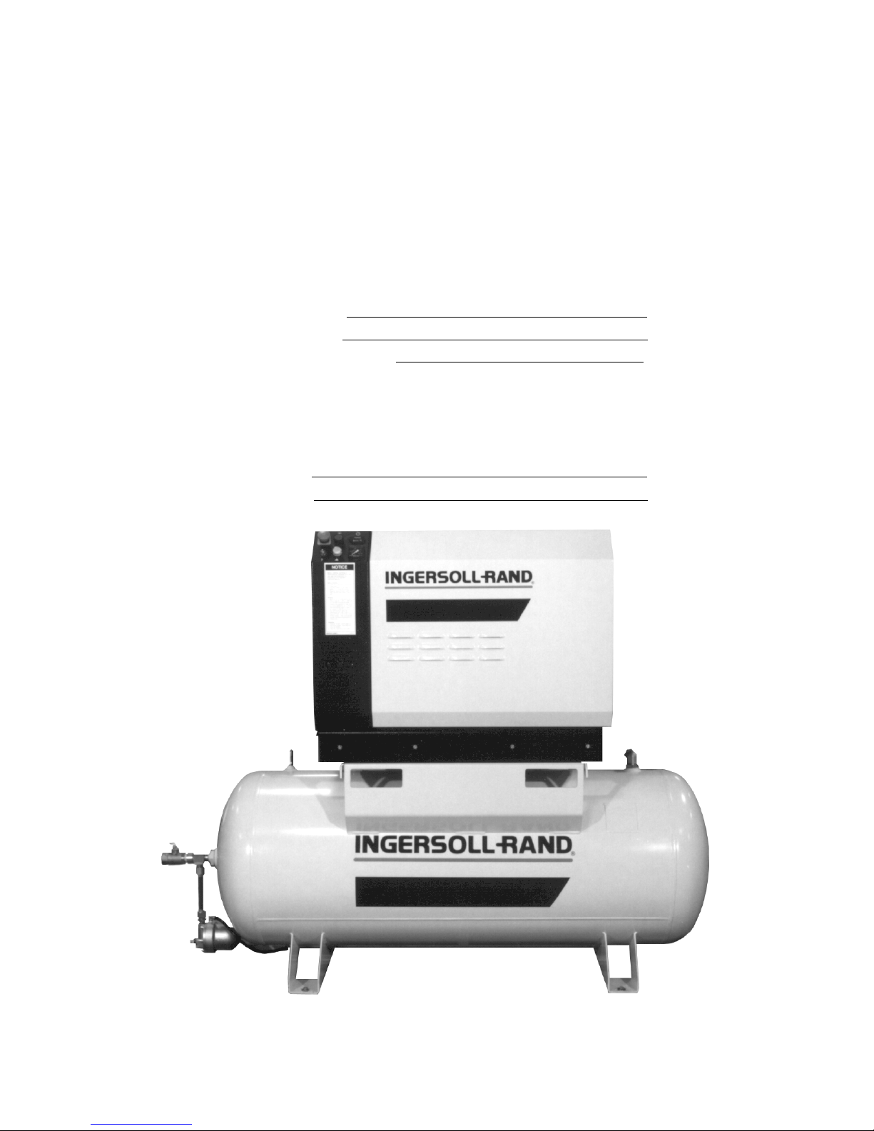
Ingersoll-Rand XF 7.5, EP 15, HP 7.5, HP 15, XF 15 Operators/instruction Manual And Parts List
...
Before installation or starting the compressor for
the first time,this manual should be studied carefully to obtain a clear knowledge of the unit and of the
duties to be performed while operating and maintaining the unit.
XF 7.5 - 15
EP 7.5 - 15
HP 7.5 - 15
XP 7.5 - 15
OPERATORS/
INSTRUCTION MANUAL
PARTS LIST
RECOMMENDED SPARES
RETAIN THIS MANUAL WITH UNIT.
This Technical manual contains IMPORTANT SAFETY DATA and should be kept with the air compressor at all times.
More Than Air. Answers.
Online answers: http://www.air.ingersoll-rand.com
APDD 702B
June 2000
BONDED WARRANTY & REGISTERED START UP
AIR COMPRESSOR GROUP
Warranty
The Company warrants that the equipment manufactured by it and delivered hereunder will be free of defects in
material and workmanship for a period of twelve months (see extended airend warranty) from the date of placing
the Equipment in operation or eighteen months (see extended airend warranty) from the date of shipment from
Davidson, NC, whichever shall first occur.The Purchaser shall be obligated to promptly report any failure to conform
to this warranty, in writing to the Company in said period, whereupon the Company shall, at its option, correct such
nonconformity, by suitable repair to such equipment or, furnish a replacement part F.O.B.point of shipment, provided the Purchaser has stored, installed maintained and operated such Equipment in accordance with good industry
practices and has complied with specific recommendations of the Company.Accessories or equipment furnished by
the Company, but manufactured by others, shall carry whatever warranty the manufacturers have conveyed to the
Company and which can be passed on to the Purchaser.The Company shall not be liable for any repairs, replacements, or adjustments to the Equipment or any costs of labor performed by the Purchaser or others without
Company’s prior written approval.
The effects of corrosion, erosion and normal wear and tear are specifically excluded.Performance warranties are
limited to those specifically stated within the Company’s proposal. Unless responsibility for meeting such performance warranties are limited to specified tests, the Company’s obligation shall be to correct in the manner and for
the period of time provided above.
THE COMPANY MAKES NO OTHER WARRANTY OR REPRESENTATION OF ANY KIND WHATSOEVER,
EXPRESSED OR IMPLIED, EXCEPT THAT OF TITLE, AND ALL IMPLIED WARRANTIES OF MERCHANTABILITY AND FITNESS FOR A PARTICULAR PURPOSE, ARE HEREBY DISCLAIMED.
Correction by the Company of nonconformities whether patent or latent, in the manner and for the period of time
provided above, shall constitute fulfillment of all liabilities of the Company for such nonconformities whether based
on contract, warranty negligence, indemnity, strict liability or otherwise with respect to or arising out of such
Equipment.
The purchaser shall not operate Equipment which is considered to be defective, without first notifying the Company
in writing of its intention to do so.Any such use of Equipment will be at Purchaser’s sole risk and liability.
Limitation of Liability
The remedies of the Purchaser set forth herein are exclusive, and the total liability of the Company with respect to
this contract or the Equipment and services furnished hereunder, in connection with the performance or breach
thereof, or from the manufacture, sale, delivery, installation, repair or technical direction covered by or furnished
under this contract, whether passed on contract, warranty negligence, indemnity, strict liability or otherwise, shall not
exceed the purchase price of the unit of Equipment upon which such liability is based.
The Company and its suppliers shall in no event be liable to the Purchaser, any successors in interest or any beneficiary or assignee of this contract for any consequential, incidental, indirect, special or punitive damages arising
out of this contract or any breach thereof, or any defect in, or failure of, or malfunction of the Equipment hereunder,
whether based upon loss of use, lost profits or revenue, interest, lost goodwill, work stoppage, impairment of other
goods, loss by reason of shutdown or non-operation, increased expenses of operation, cost of purchase of replacement power or claims of Purchaser or customers of Purchaser for service interruption whether or not such loss or
damage is based on contract, warranty, negligence, indemnity, strict liability or otherwise.
EXTENDED AIREND WARRANTY
The Ingersoll-Rand Company Rotary Screw Air Compressor that has been
filled prior to its original shipment from Ingersoll-Rand Company with ULTRA
COOLANT and which has been operated solely on ULTRA COOLANT thereafter shall have its AIREND warranted for twenty four (24) months from the
date of placing the COMPRESSOR in operation or thirty (30) months from the
date of shipment, whichever occurs first.
Except for the above warranty period, the standard warranty provisions shall
apply and the conditions outlined herein are understood to be a supplement to
the standard Ingersoll-Rand Company warranty.
©INGERSOLL-RAND COMPANY
ROTARY SCREW AIR COMPRESSOR
This unit was purchased from
–––––––––––––––––––––––––––––––––––––––––––––––––––––––––––
–––––––––––––––––––––––––––––––––––––––––––––––––––––––––––
–––––––––––––––––––––––––––––––––––––––––––––––––––––––––––
Ingersoll-Rand Company reserves the right to make changes or add
improvements without notice and without incurring any obligation to make
such changes or add such improvements to products sold previously.
No.of units on order:
Customer Order No:
Ingersoll-Rand Co. Order No.:
For ready reference:
Record the serial number and model number of your unit here.
Serial Number:
Model Number:
1

TABLE OF CONTENTS
0.0 SAFETY AND WARNINGS
0.1 safety instructions
0.2 safety precautions
0.3 decals
1.0 RECEIPT OF EQUIPMENT
1.1 inspection
1.2 unpacking and handling
6.0 REFERENCE DRAWINGS
6.1 electrical schematic - full voltage
6.2 electrical schematic - star-delta
6.3 piping diagram
6.4 found. plan - 80 gal tank mounted - enclosed
6.5 found. plan - 80 gal tank mounted - unenclosed
6.6 found. plan - 120 gal tank mounted - enclosed
6.7 found. plan - 120 gal tank mounted - unenclosed
6.8 found. plan - base mounted - enclosed
6.9 found. plan - base mounted - unenclosed
6.10 typical system flow diagram
2.0 INSTALLATION
2.1 ventilation
2.2 foundation requirements
2.3 outdoor installations
2.4 piping
2.5 electrical installation
2.6 voltage conversion
2.7 rotation check
2.8 before starting - starting - stopping
3.0 SYSTEMS
3.1 general system information
3.2 coolant system
3.3 air systems
3.4 capacity control
3.5 pressure switch adjustment
4.0 MAINTENANCE
4.1 maintenance schedule
4.2 maintenance records
4.3 maintenance procedures
4.4 pressure relief valve check
4.5 sheave alignment
4.6 drive belt
4.7 belt tension
4.8 shaft seal replacement
4.9 inlet air filter element
4.10 coolant filter element
4.11 coolant change
4.12 coolant hose
4.13 coolant separator element
4.14 separator tank scavenge
check valve/screen/orifice
4.15 cooler cores/cleaning
4.16 motor bearing maintenance-stored units
7.0 PARTS LIST
7.1 introduction
7.2 parts listing
starter box assembly
starter assembly - full voltage
starter assembly - star-delta
major components assembly
drive components
control piping assembly
cooler box assembly with aftercooler
cooler box assembly without aftercooler
80 gallon receiver tank assembly
120 gallon receiver tank assembly
canopy assembly option
table - O-rings
7.3 service and option kits
7.4 recommended spare parts
8.0 MAINTENANCE RECORD
GENERAL INFORMATION
Cooling Air Flow:
60 Hz: 1800 cfm (0.85 m3/sec)
50 Hz: 1500 cfm (0.71 m3/sec)
Ambient Temperature Limit: 35°F to 115°F (2°C to 46°C)
Coolant: Factory Filled ULTRA COOLANT
Coolant Change: 8,000 hours or two years, whichever
comes first, when using ULTRA COOLANT
Coolant Capacity: 1.5 GAL (5.75L)
5.0 TROUBLE SHOOTING
2
DischargeTemperature Limit: 228°F (109°C)
Tools:U.S. Standard and metric are required to perform
maintenance
0.0 SAFETY AND WARNINGS
0.1 SAFETY INSTRUCTIONS
Before you install this air compressor you should take the time
to carefully read all the instructions contained in this manual.
Electricity and compressed air have the potential to cause
severe personal injury or property damage.
Before installing, wiring, starting, operating or making any
adjustments, identify the components of the air compressor
using this manual as a guide.
The operator should use common sense and good working
practices while operating and maintaining this unit. Follow all
codes, pipe adequately, understand the starting and stopping
sequence. Check the safety devices by following the procedure contained in this manual.
Maintenance should be done by qualified personnel, adequately equipped with proper tools. Follow the maintenance
schedules as outlined in the operators manual to ensure problem free operation after start up.
0.2 SAFETY PRECAUTIONS
SAFETY PRECAUTIONS
BEFORE PROCEEDING, READ CAREFULLY BEFORE INSTALLING THE
COMPRESSOR OR PERFORMING ANY MAINTENANCE
Safety instructions in the operators manual are bold-faced for
emphasis. The signal words DANGER, WARNING and CAUTION are used to indicate hazard seriousness levels as follows:
Danger is used to indicate the presence of
D! DANGER
! WARNING
! CAUTION
NOTICE
a hazard which will cause severe personal
injury, death, or substantial property damage if the warning is ignored.
Warning is used to indicate the presence of
a hazard which can cause severe personal
injury, death, or substantial property damage if the warning is ignored.
Caution is used to indicate the presence of
a hazard whichwill or can cause minor personal injury or property damage if the warning is ignored.
Notice is used to notify people of installation, operation,or maintenance information
which is important but not hazard-related.
WARNING
COMPRESSED AIR AND ELECTRICITY
ARE DANGEROUS.
BEFORE DOING ANY WORK ON THIS
UNIT, BE SURE THE ELECTRICAL SUPPLY HAS BEEN CUT OFF–LOCKED &
TAGGED AND THE ENTIRE COMPRESSOR SYSTEM HAS BEEN VENTED OF
ALL PRESSURE.
1. Do not remove the covers, loosen or
r e m ove any fittings, connections or
devices when this unit is in operation.
Hot liquid and air under pressure that
are contained within this unit can cause
severe injury or death.
2. The compressor has high and dangerous voltage in the motor starter and
control box. All installations must be in
accordance with recognized electrical
codes. Before working on the electrical
system, be sure to remove voltage from
the system by use of a manual-disconnect-switch. A circuit breaker or fuse
safety switch must be provided in the
electrical supply line leading to the
compressor.
Those responsible for installation of
this equipment must provide suitable
g ro u n d s , maintenance clearance and
lightning arrestors for all electrical components as stipulated in O. S . H . A .
1910.308 through 1910.329.
3. Do not operate the compressor at
higher discharge pressure than those
specified on the Compressor Nameplate
or motor overload will occur.This condition will result in compressor motor
shutdown.
4. Use only safety solvent for cleaning
the compressor and auxiliary equipment.
5. Install a manual shut off valve (isolation type) in the discharge line.When a
safety valve is installed between the isolation valve and the compressor,it must
have sufficient capacity to relieve the
full capacity of the compressor(s).
6 . W h e n ever pressure is released
through the pressure relief valve, it is
due to excessive pressure in the system.The cause for the excessive pressure should be investigated immediately.
7.Before doing any mechanical work on
the compressor:
a.) Shut the unit down.
b.) Electrically isolate the compressor
by use of the manual disconnect switch
in the power line to the unit. Lock and
tag the switch so that it cannot be operated.
c.) Vent pressure from the compressor
and isolate the unit from any other
source of air.
8. There can be adverse effects if compressor lubricants are allowed to enter
plant air systems.
Air line separators, properly selected
and installed, will minimize any liquid
carry-over.
The use of plastic bowls on line filters
without metal guards can be hazardous.
From a safety standpoint, metal bowls
should be used on any pressurized system.Review of your plant air line system
is recommended.
9.When a receiver is installed, it is recommended that occupational safety and
health standards as covered in the
Federal Register, Volume 36, nu m b e r
1 0 5 , p a rt 11, p a r agraph 1910.169 be
adhered to in the installation and maintenance of this receiver.
10. Before starting the compressor, its
maintenance instructions should be
thoroughly read and understood.
1 1 . After maintenance functions are
completed, covers and guards must be
replaced.
3
! SAFETY SHUTDOWN CHECK HIGH AIR TEMPERATURE
There is a high discharge air temperature shutdown function built into each compressor. It is factory preset at 228°F (109°C).This function should be checked at regular intervals for proper operation,once a month
is recommended.
PROCEDURE:
1. Block off the cooling air discharge.
2.The compressor discharge temperature will rise at a rapid rate. Shutdown should occur when the discharge temperature reaches the pre-set maximum discharge air temperature setting.
! WARNING
Failure to adhere to these recommendations can result in mechanical failure,property damage and serious
injury or death.
All air and water inlet, and air and water discharge pipework to and from the inlet and discharge port connections must take into account vibration, pulsations, temperature, maximum pressure applied, corrosion
and chemical resistance. In addition, it should be noted that lubricated compressors will discharge some
oil into the air stream;therefore, compatibility between discharge piping, system accessories and software
must be assured.
For the foregoing reasons, the use of plastic piping,soldered copper fittings and rubber hose as discharge
piping is not recommended.In addition,flexible joints and/or flex lines can only be considered for such purposes if their specifications fit the operating parameters of the system.
It is the responsibility of the installer and owner to provide the appropriate service pipework to and from
the machine.
! WARNING
“Ingersoll-Rand air compressors are not designed, intended, or approved for breathing air applications.
Ingersoll-Rand does not approve specialized equipment for breathing air application and assumes no
responsibility or liability for compressors used for breathing air services.”
4
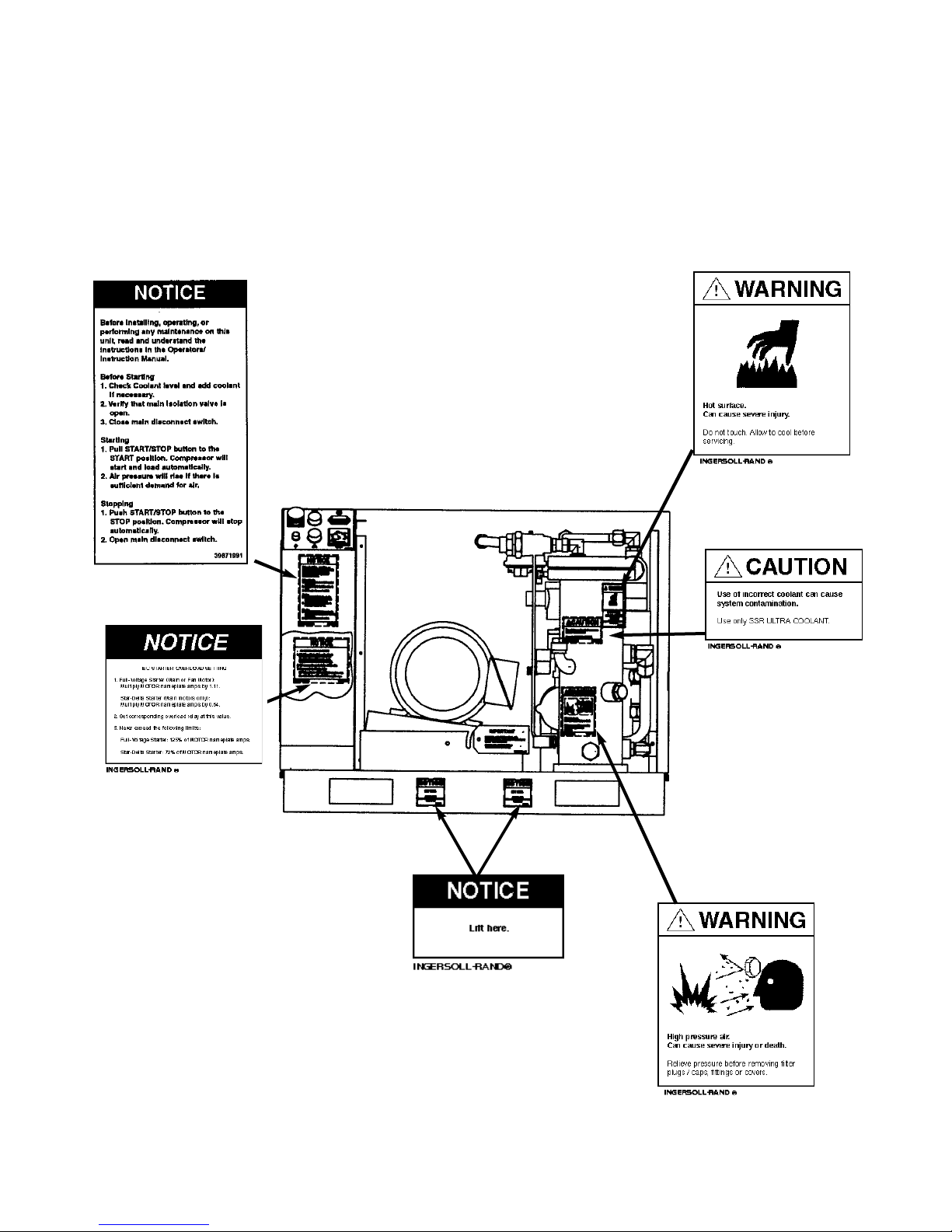
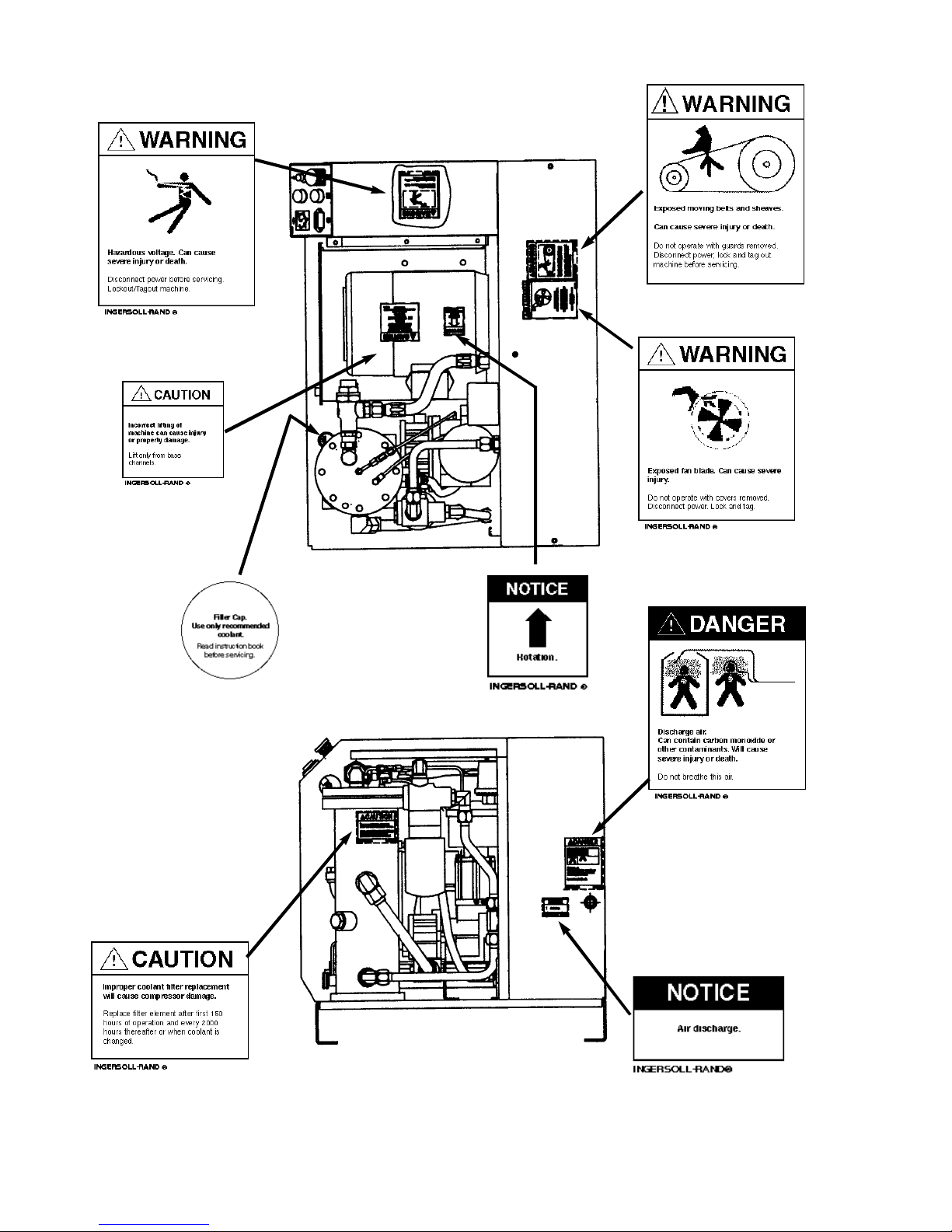
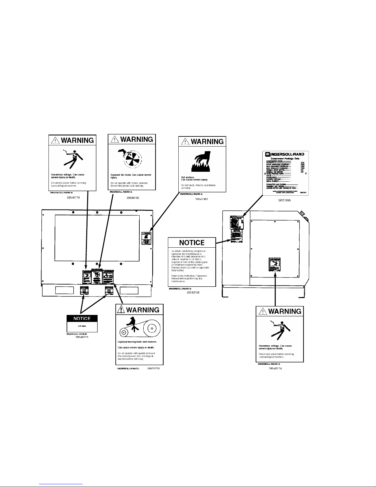
0.3 DECALS
This section contains representative examples of
decals which will be appearing throughout this manual
and are applied to the compressor unit.
If for some reason a decal is defaced, parts are
replaced or painted over, we recommend that you
obtain a replacement (See Recommended Spare
Parts List for Decal Kit Number).
39541362
39921804
39879762 I-R LOGO ON RECEIVER TANK
39868419 IR LOGO ON CANOPY (ENCLOSED UNITS)
39540265
39540273
39540240
5
39540174
39540232
INGERSOLLrAND®
39859236
3954190
39544143
39540281
39544150
*THESE DECALS ARE LOCATED ON THE END OF THE
RECEIVER TANK ON TANK MOUNTED UNITS.
39540166*
39540257*
6
7

1.0 RECEIPT OF EQUIPMENT
1.1 INSPECTION
2.2 FOUNDATION REQUIREMENTS
The compressor can be installed on any level floor that
is capable of supporting the weight.
When you receive the compressor please inspect it
closely.Any indication of careless handling by the carrier should be noted on the delivery receipt especially
if the compressor will not be immediately un-crated.
Obtaining the delivery man’s signed agreement to any
noted damages will facilitate any future insurance
claims.
1.2 UNPACKING AND HANDLING
The compressor package has been mounted on a
wooden shipping base which will allow fork lifting
under the compressor base to facilitate handling during shipment. Care in positioning the forklift is important because the location of the center of gravity is
strongly affected by the location of the airend and drive
motor.
The wooden base must be removed prior to installation.
2.0 INSTALLATION
2.1 VENTILATION
Air cooled air compressors produce large amounts of
heat. Because of this large heat production, the compressor must be placed in a room with adequate ventilation.
If heated air from the compressor exhaust is allowed to
re-circulate back to the compressor, the compressor
will overheat and shut down.This heat must be
exhausted from the room.You should take this into
consideration when deciding where to place the compressor within the building. Sufficient clearance must
be allowed around the compressor to perform the
required maintenance.
Ambient temperatures higher than 115°F (46°C)
should be avoided as well as areas of high humidity. Also consider the environment near the compressor.
DUST, CHEMICALS, METAL FILINGS, PAINT FUMES,
and OVERSPRAY should be avoided as well as any
other conditions which might be detrimental to the
proper operation of the compressor.
When sound transmission is of particular importance,
it is often helpful to install a sheet of rubber-fabric-matting, under the compressor baseplate or receiver tank
feet to reduce the possibility of resonant sounds being
transmitted or amplified through the floor.
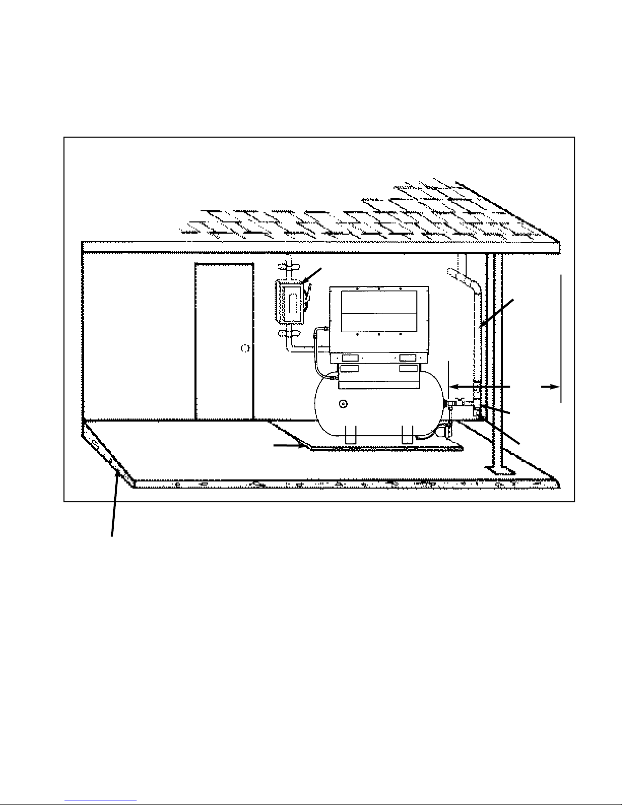
2.3 OUTDOOR INSTALLATIONS
When a compressor must be installed outside, there
are certain items that should be incorporated into the
installation to help assure trouble free operation.These
items have been listed below plus Figure 2.3-1 has
been included to show a typical outdoor protected
installation.The unit must be purchased with the
NEMA 4 option to provide watertight electrics, and a
TEFC motor.
• The compressor should be on a concrete pad
designed to drain water away.If the concrete pad is
sloped, then the compressor must be leveled.
• The roof of the shelter should overhang the compressor a minimum of 4 feet (1.2m) on all sides to prevent
direct rain and snow from falling on the unit.
• The unit must be arranged under the shelter in a way
that prevents air recirculation (i.e. hot exhaust back to
the package inlet).
• If the installation includes more than one compressor,
the hot air exhaust should not be directed towards the
fresh air intake of the second unit or an Air Dryer.
• If a standard machine is to be installed outside, the
ambient temperature must never drop below 35°F
(2°C) or freezing of condensate will result.
• Power disconnect switch must be within the compressor operator’s line of sight and should be in close proximity to the unit.
• Condensate drains must never be allowed to dump
on the ground. Pipe to a suitable sump for future collection, disposal or separation of lubricant and water
mixture.
• Incoming power connections must use suitable connectors for outdoor weather tight service.
• Sufficient clearance must be allowed on all four sides
of the unit for service access. If possible, access by a
fork lift and/or an overhead beam hoist should be kept
in mind (for eventual service to airend or motor).
8
• If the area around the installation contains fine airborne dust or lint and fibers etc., then the unit should
be purchased with the TEFC motor option.
• Some type of protection such as a fence or security
system, should be provided to prevent unauthorized
access.
POWER
DISCONNECT SWITCH
DISCHARGE
PIPE
(STEEL)
AREA SHOULD BE
SECURED WITH A FENCE
OR SECURITY SYSTEM
SLOPING
CONCRETE
PAD
FIGURE 2.3-1 TYPICAL OUTDOOR SHELTERED INSTALLATION
PRESSURE
TREATED
TIMBER TO
LEVEL
4’
(1.2m)
OVERHANG
(ALL
SIDES)
ISOLATION
VALVE
DRIP
LEG
35°F (2°C) AND ABOVE
9

2.4 PIPING
It is essential when installing a new compressor to
review the total plant air system.This is to insure a safe
and effective total system.
The use of plastic bowls on line filters without metal
guards can be hazardous.Their safety can be affected
by either synthetic lubricants or the additives used in
mineral oils. From a safety standpoint, metal bowls
should be used on any pressurized system.
! WARNING
Do not use plastic pipe, soldered copper fittings
or rubber hose for discharge piping.
Figure 2.4-1 indicates the approximate moisture content in compressed air at various operating points.
Contact your local Ingersoll-Rand Distributor or Air
Center for assistance in selecting correct IngersollRand filtration or drying products.
200
Moisture Content of Compressed Air
Condensed water occurs naturally in air lines as a result
of compression. Moisture vapor in ambient air is concentrated when pressurized and condenses when cooled in
downstream air piping.
Moisture in compressed air is responsible for costly
problems in almost every application that relies on compressed air. Some common problems caused by moisture are: rusting and scaling in pipelines, clogging of
instruments, sticking of control valves, and freezing of
outdoor compressed air lines. Any of these could result
in partial or total shutdown of the compressed air system.
The compressed air discharging from this compressor
will be at some elevated temperature and will therefore
contain amounts of water vapor. As this air cools, the
vapor will condense within the piping system.
IMPORTANT:The drain line must slope downward from
the trap to work properly.
NOTE: For ease of inspection of the automatic drain
trap operation, the drain piping should include an open
funnel or some type of sight flow indicator.
160
120
80
40
0
DEW POINT
❏ without 100°F (with 35°F -40°F (Desiccant
Aftercooling Aftercooler) (Refrigerated Dryer)
Dryer)
FIGURE 2.4-1 MOISTURE CONTENT OF
COMPRESSED AIR
It is possible that additional condensation can occur if
the downstream piping cools the air even further.
Therefore, low points in the piping system should be
provided with driplegs and traps.
Compressed air dryers reduce the water vapor concentration and prevent liquid water formation in compressed
air lines. Dryers are a necessary companion to filters,
aftercoolers, and automatic drains for improving the productivity of compressed air systems.Two types of dryers, refrigerated or desiccant , are used to correct moisture related problems in a compressed air system.
Refrigerated dryers are normally specified where compressed air pressure dew points of 33°F to 39°F (.5°C to
4°C) are adequate. Desiccant dryers are required where
pressure dew points must be below 33°F (.5°C).
10
IMPORTANT: Discharge piping should be at least as
large as the discharge connection at the compressor.
All piping and fittings must be suitably rated for the
discharge pressure and temperature.
A careful review of piping size from the compressor
connection point is essential. Length of pipe, size of
pipe, number and type of fittings and valves must be
considered for minimum air pressure drop and optimum efficiency of your compressor.
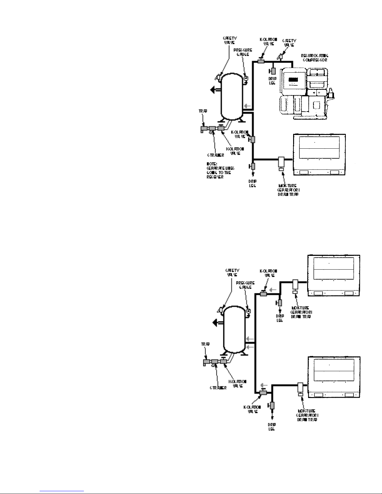
NOTE: Screw type compressors should not be
installed in air systems with reciprocating compressors without a means of pulsation isolation, such as a
common receiver tank.We recommend both types of
compressor units be piped to a common receiver utilizing individual air lines. See Figure 2.4-2.
When two rotary units are operated in parallel, provide an isolation valve and drain trap for each compressor before the common receiver.
See Figure 2.4-3
To assure long trouble free operation of a compressor
operating with On-line/ Off-line and Auto Stop/Start
control, the system volume must be large enough to
keep the load/unload cycles to a minimum.This may
require the installation of a receiver down stream of
the compressor. Baseplate mounted units must be
piped to a receiver if installed in a system with insufficient volume to keep compressor cycling to a minimum. If equipment such as filters or air dryers, is
installed in the main piping system, they must be
sized to handle the entire flow of the compressor and
an air receiver must be placed in the system between
the compressor discharge and the equipment,
regardless of system volume.
This will prevent quick cycling of the compressor
which results in large fluctuations in system pressure.
ROTARY
COMPRESSOR
FIGURE 2.4-2 ROTARY-RECIP IN PARALLEL
ROTARY
COMPRESSOR
FIGURE 2.4-3 ROTARY-TWO
COMPRESSOR SYSTEM
ROTARY
COMPRESSOR
11
2.5 ELECTRICAL INSTALLATION
Before proceeding further, we recommend that you
review the safety data in the front of this manual.
Locate the compressor data plate on the left end of
the cooler box next to the control box (See Figure
2.5-1).
The data plate lists the rated operating pressure, the
maximum discharge pressure, the electric motor characteristics and power.
Confirm that the line voltage and compressor nameplate voltage are the same.
The standard control box meets the intent of NEMA 1
guidelines.
It will be necessary to make a hole in the control box
for the incoming power connection. Care should be
taken to not allow metal shavings to enter the starter
and other electrical components within the box. After
making the power inlet hole, all shavings and debris
must be removed from inside of control box before
power is turned on.
Inspect the motor and control wiring for tightness.
Replace control box door.
2.6 VOLTAGE CONVERSION
IMPORTANT:This procedure should only be carried out
by a qualified electrician, electrical contractor or your
local Ingersoll Rand Distributor or Air Center.
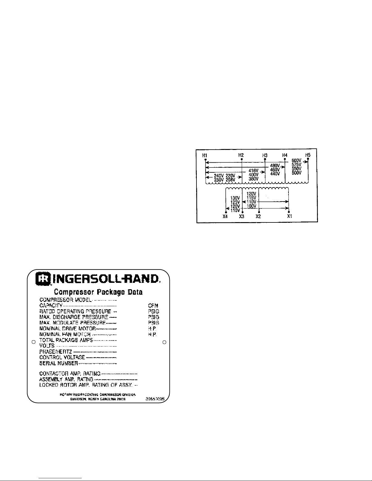
PRIMARY
Incoming power should be connected per the electrical schematic at the rear of this manual (See Section
6.0). Confirm that all electrical connections are made
and tightened. Confirm that the control transformer is
wired correctly for supply voltage (See Figure 2.6-1).
SECONDARY
FIGURE 2.6-1 CONTROL TRANSFORMER
CONNECTIONS
NOTE:This procedure applies only to units manufactured to multi-voltage specifications. Compressor data
plate and motor nameplate must indicate multiple voltages.
FIGURE 2.5-1 COMPRESSOR DATA PLATE
12
PROCEDURE:
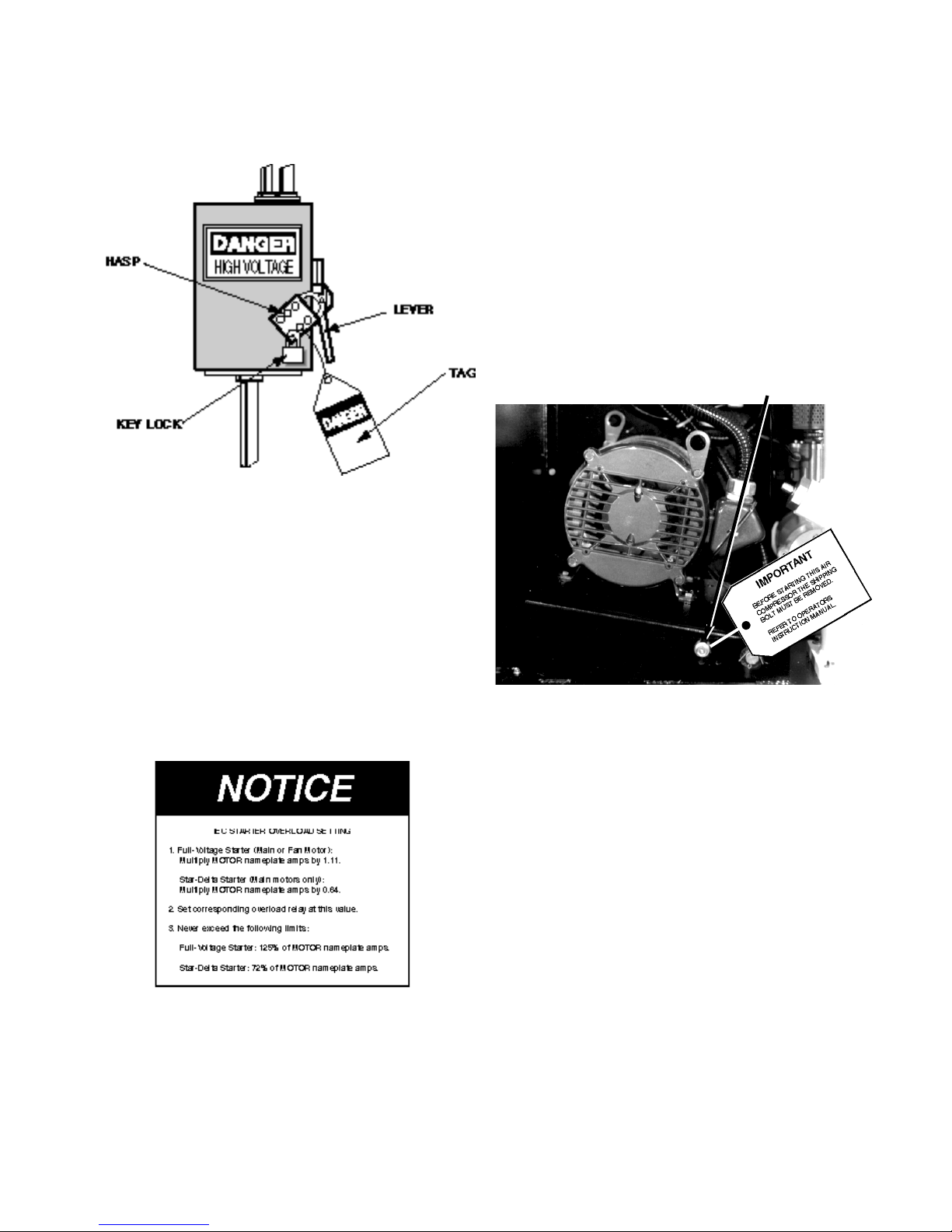
2.7 ROTATION CHECK.
Put main disconnect in the OFF position, lock and tag
(See Figure 2.6-2).
FIGURE 2.6-2 MAIN DISCONNECT
LOCKED AND TAGGED
Open the motor junction box on the side of the motor.
Locate the rotation decal on the motor and check for
correct rotation.The correct rotation when viewed from
the opposite drive end of the motor is clockwise.
If compressor is operated in the opposite direction of
rotation, airend damage can result and is not warrantable.
The unit is shipped with a bolt in the motor support to
prevent possible belt damage caused by bouncing during shipment.This bolt must be remove prior to checking motor rotation or operating the unit.
Locate the shipping bolt in the motor support as shown
in Figure 2.7-1. and remove.
SHIPPING BOLT
Reconnect the motor to the desired voltage. Use the
connection diagram provided on the motor as a guide.
Reconnect the primary side of the control transformer
for the desired voltage, as shown on the control transformer wiring decal.
Adjust motor overload setting as outlined below in
Figure 2.6-3.
FIGURE 2.6-3 MOTOR OVERLOAD SETTING
FIGURE 2.7-1 SHIPPING BOLT LOCATION
For the compressor motor rotation check, the motor
jogging should be as short a time as possible.
1. Ensure that the Stop button is in the stop
(depressed) position.
2. Check coolant level.To check coolant level, slowly
loosen the fill plug one complete turn. As the fill plug is
unscrewed approximately one turn, a small amount of
pressure may be released. Do not remove the fill plug
until all pressure has been vented. Once pressure is
vented, finish removing the fill plug.The proper coolant
level is when the coolant is even with the top of the fill
port. Add coolant if necessary.
3. Replace and tighten fill plug.
4. Close the main disconnect switch (ON position).
Make sure all wiring connections are tight.
Put main disconnect in the ON position and check
motor rotation, as outlined in Section 2.7 of this manual.
5.Verify that the main isolation valve is open.
6. Open the canopy enclosure if machine is so
13
equipped. Push the Start button to start the unit and
immediately depress (push) the Stop button to stop the
unit.
Observe the compressor drive motor shaft. The rotation should be in accordance with the directional arrow
decal on the motor.
Should the motor rotation not be correct, put the main
disconnect in the OFF position, lock and tag.
Interchange any two line connections (L1 ,L2, or L3) at
the starter. Close the control box cover. Recheck for
correct rotation.
Starting
1. Push the Start button and release.The compressor
will start and then load automatically if line pressure is
below the lower set point of the pressure switch.
Stopping
1. Depress the Stop button to the OFF position.
Compressor will stop immediately.
2. Open the main disconnect switch (OFF position).
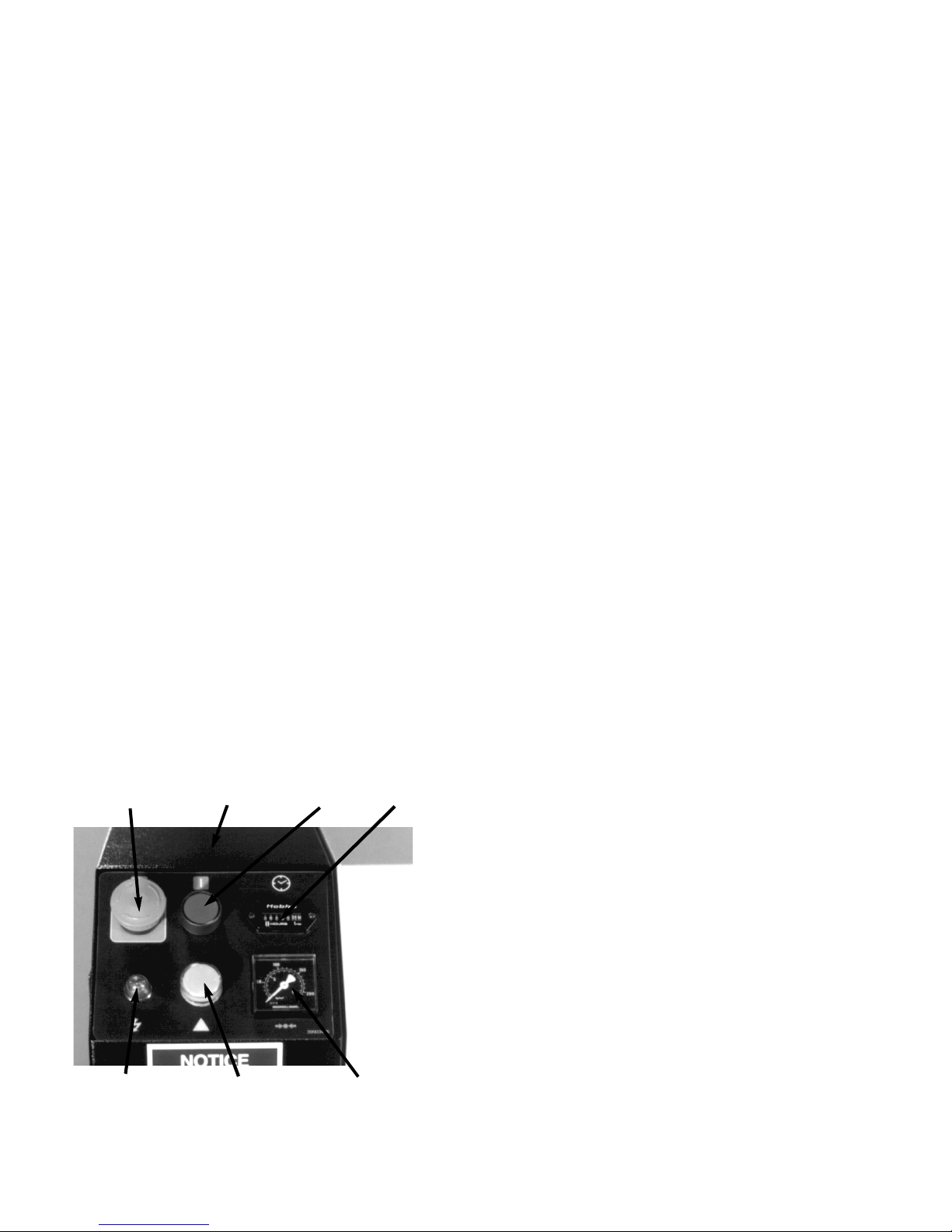
2.8 BEFORE STARTING - STARTING - STOPPING
Read and understand the following instructions
before operating or performing any maintenance
on this unit.
Before Starting:
1. Ensure that Stop push button is in the OFF
(depressed) position (See Figure 2.8-1).
2. Check coolant level.To check coolant level, slowly
loosen the fill plug one complete turn. As the fill plug is
unscrewed approximately one turn, a small amount of
pressure may be released. Do not remove the fill plug
until all pressure has been vented. Once pressure is
vented, finish removing the fill plug.The proper coolant
level is when the coolant is even with the top of the fill
port. Add coolant if necessary.
3. Replace and tighten fill plug.
4. Close the main disconnect switch (ON position).
5.Verify that the main isolation valve is open.
STOP
BUTTON
CONTROL
BOX
START
BUTTON
HOUR
METER
3.0 SYSTEMS
3.1 GENERAL SYSTEM INFORMATION
The compressor is an electric motor driven, single
stage, rotary screw compressor, complete with supporting components to make a fully functional unit. A
standard compressor is composed of the following:
Inlet air filter
Drive motor
Airend
Pressurized coolant system with cooler & filter
Separation system
Capacity control
Instruments
Safety devices
Compression in the rotary screw type air compressor
is created by the meshing of two helical rotors (male
and female) on parallel shafts, enclosed in a heavy
duty iron housing, with air inlet and outlet ports located
on opposite ends.The grooves of the female rotor
mesh with and are driven by the male rotor. Bearings
on both ends of the rotors are used to support the
rotor both laterally and axially.
POWER ON
LIGHT
AUTO RESTART
LIGHT
FIGURE 2.8-1 CONTROL BOX
14
PRESSURE
GAUGE
3.2 COOLANT SYSTEM
The coolant system consists of a separator tank, thermostatic element, coolant filter, coolant cooler with
fans, and a separator element.When the unit is operating, the coolant is pressurized and forced to the compressor bearings.The compressor is provided with a
temperature switch which will shut the unit down in
case of excessive temperature, 228°F (109°C).
Effective coolant filtration is provided by the use of a
screw on, automotive type, heavy duty coolant filter.
The compressor is designed for operation in an ambient range of 35°F to 115°F (2°C to 46°C).The standard maximum temperature 115°F (46°) is applicable
up to an elevation of 3300 ft. (1000 m).

Coolant
3.3 AIR SYSTEM
Rotary screw compressor fluids have a triple function
to perform.They lubricate the bearings and contacting
surfaces of the rotors, seal internal clearances within
the rotor chamber, and provide for the cooling of the
compression process.The bulk of the fluid is actually
used for cooling, with only small amounts used for
lubrication and sealing.
SSR air compressors are factory filled with SSR
ULTRA COOLANT. ULTRA COOLANT is designed
to operate for 8,000 hours or two years, whichever
comes first.The coolant must be changed at these
intervals to avoid breakdown and equipment damage.
Circulation of Coolant
Coolant is forced by air pressure from the separator
tank to the thermostatic element.The position of the
element (a direct result of coolant temperature) will
determine whether the coolant circulates through the
cooler, bypasses the cooler, or mixes the two paths
together to maintain an optimum compressor injection
temperature.This temperature is controlled to preclude
the possibility of water vapor condensing. By injecting
coolant at a sufficiently high temperature, the discharge air coolant mixture temperature will be kept
above the dew point.
Before being injected into the airend, all coolant flows
through the coolant filter. It is a full-flow, spin-on element, rated at 4 micron.There is a differential-pressure
bypass valve in the element that opens in the event
that the pressure drop across the element rises to as
high as 15 psi (1 bar), which indicates an excessively
fouled element as well as poor maintenance practice.
Coolant/Air Separator System
Components and Flow
The air system is composed of:
Inlet air filter
Inlet valve
Airend
Coolant/Air separator
Minimum pressure check valve (MPCV)
Aftercooler
The direction of flow is from the inlet filter to the aftercooler.
Functions of Components
Inlet air filter, filters the incoming air, trapping 99.9% of
particles 3 micron and larger.
Inlet valve opens full for on-line operation.The valve
closes in the off-line mode and at shutdown which prevents back flow of the compressed air.
The airend compresses the air.
The separator tank removes most of the coolant from
the air.
The separator element performs the final separation of
coolant and cleaning of the air prior to leaving the
compressor.
The minimum pressure check valve keeps the separa-
tor tank and separator element at a minimum pressure
to ensure adequate oil flow and proper coolant/air separation. It also prevents line pressure from exhausting
back through the airend at shutdown and during periods of unloaded operation.
The aftercooler cools the air prior to leaving the package.
The coolant/air separation system is composed of a
separator tank with specially designed internals and a
coalescing type separator element located inside the
tank.
The air-coolant mixture discharges from the airend into
the separator tank.The majority of coolant is separated while in the separator tank and the coalescing separator filter element is used for final cleaning of the air
prior to the customer’s system.The system removes
nearly all of the coolant from the discharge air.The
separated coolant is returned to the coolant system
and the air passes to the compressed air system.
15
3.4 CAPACITY CONTROL
On Line/Off Line With Automatic Start/Stop
Control
4. Set the off-line pressure by turning screw 2.Turn
screw counter-clockwise to increase setting or clockwise to decrease setting (indicated by pointer 3).
The compressor will deliver air at full capacity, (the
compressor maximum efficiency condition) or will
operate at zero capacity with high receiver pressure
(the compressor minimum power condition), while the
unit continues to run.
When the compressor starts and line pressure is
below the lower setting of the line pressure switch,
control solenoid 1SV will be energized (closed), inlet
valve will open, and the compressor will load.When
the line pressure reaches the upper setting of the
pressure switch, the compressor will unload by deenergizing (opening) 1SV and closing the inlet valve.
Solenoid 1SV relieves the internal pressure of the
compressor back to the inlet filter.The only adjustment
required is setting of the pressure switch.
A time delay relay is energized and begins to time out.
The timer, mounted in the control box, is factory set at
10 minutes. It will continue to operate for as long as its
time setting, after which a relay contact opens to deenergize the compressor starter coil. At the same
time, an amber light (1LT) on the control box is lit to
indicate the compressor has shut down automatically
and will restart automatically.The automatic restart will
take place when the line pressure drops to the lower
setting of the pressure switch. Adjusting the
Auto/Restart timer below the 10 minute factory
setting may shorten the life of the compressor
drive motor.
CAUTION:
DO NOT EXCEED MAXIMUM DISCHARGE PRESSURE (LOCATED ON COMPRESSOR DATA
PLATE).
5.Turn power back on, start compressor and test
adjustment(s) made. If necessary, readjust according
to steps 1-4 above.
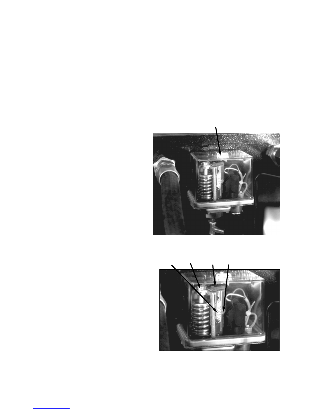
PRESSURE SWITCH
3.5 PRESSURE SWITCH ADJUSTMENT
Locate the pressure switch as shown in Figure 3.5-1.
The pressure switch can be adjusted using the following procedure:
1. Open, lock and tag the main electrical disconnect.
Do not adjust the pressure switch with power on or
machine operating.
2. Remove pressure switch cover by turning the cover
screw counterclockwise.
NOTE: It is required that the load or on-line pressure
be set first, before the unload or off-line pressure is
set.
3. Set the on-line pressure by turning screw 5 (See
Figure 3.5-2).Turn clockwise to increase setting or
counter-clockwise to decrease setting (indicated by
pointer 4).
16
FIGURE 3.5-1 PRESSURE SWITCH LOCATION
4
5
2
3
FIGURE 3.5-2 PRESSURE SWITCH ADJUSTMENT

4.0 MAINTENANCE
4.1 MAINTENANCE SCHEDULE
THE MAINTENANCE SCHEDULE SPECIFIES ALL RECOMMENDED MAINTENANCE REQUIRED TO KEEP THE COMPRESSOR IN GOOD OPERATING CONDITION.SERVICE AT THE INTERVAL LISTED OR AFTER THAT NUMBER OF
HOURS, WHICHEVER OCCURS FIRST.
TIME INTERVAL (WHICHEVER COMES FIRST)
ACTION PART OR ITEM HOURS 1WK 1 MO 6 MO 9 MO YEARLY 2YR
INSPECT COOLANT LEVEL VISIBLE IN FILL PORT WEEKLY X
INSPECT AIR FILTER WEEKLY X
REPLACE COOLANT FILTER* 150 X
REPLACE COOLANT FILTER* 2000 X
INSPECT HOSES 1000 X
INSPECT DRIVE BELTS 500 X
REPLACE DRIVE BELTS 8000 X
CHECK HIGH AIR TEMP.SWITCH 1000 X
CHECK OPERATE PRESSURE RELIEF VALVES 1000 X
CLEAN SEPARATOR SCAVENGE ORIFICE 1000 X
CLEAN COOLERS CORES** 4000 X
REPLACE AIR FILTER* 2500 X
REPLACE SEPARATOR ELEMENT* 4000 X
REPLACE ULTRA COOLANT 8000 X
REPLACE SHAFT SEAL 8000 X
(WHEN COLD)
(INITIAL CHANGE ONLY)
(SUBSEQUENT CHANGES)
*IN VERY CLEAN OPERATING ENVIRONMENTS AND WHERE INLET AIR FILTER IS CHANGED ATTHE ABOVE PRESCRIBED INTERVALS.IN EXTREME
DIRTY ENVIRONMENT CHANGE DRIVE BELTS, COOLANT, FILTERS, AND SEPARATOR ELEMENTS MORE FREQUENTLY.
**CLEAN COOLER CORES IF UNIT SHUTDOWN OCCURS ON HIGH AIR TEMPERATURE.
4.2 MAINTENANCE RECORDS
ing is heeded.
Read Safety Instructions.
It is very important that you, the owner, keep accurate
and detailed records of all maintenance work you or
the Ingersoll-Rand Distributor or Air Center perform on
your compressor.This includes, but is not limited to,
coolant, coolant filter, separator element, inlet air filter,
drive belts, shaft seals and so forth.This information
must be kept by you, the owner, should you require
Have a well equipped mechanic’s tool box with English
and Metric sockets. (Special tools when needed will be
listed under each appropriate procedure).
Have an OSHA approved air nozzle and compressed
air.(International - local codes may apply).
Have recommended spare parts on hand (See listing
in back of this manual.
warranty service work by your Ingersoll-Rand
Distributor or Air Center. Maintenance record sheets
! WARNING
are located at the back of this manual.
When the unit is shut down, residual pressure
4.3 MAINTENANCE PROCEDURES
can be trapped within the compressor system.
This pressure must be vented from the system
Before starting any maintenance, be certain the follow-
prior to beginning any service work.
17

Before beginning any work on the compressor, open,
lock and tag the main electrical disconnect and
close the isolation valve on the compressor discharge.Wait 2 minutes after stopping to allow internal pressure to dissipate.Vent residual pressure
from the unit by slowly unscrewing the coolant fill
plug one turn. Unscrewing the fill plug opens a vent
hole, drilled in the plug, allowing the pressure to
release to atmosphere (See Figure
4.3-1). A slight mist or oil droplets may be visible
during venting. Do not remove fill plug until all pressure has vented from the unit. Also vent piping by
slightly opening the drip leg valve.When opening
the drain valve or removing the coolant fill plug,
stand clear of the valve discharge, wear work gloves
and appropriate eye protection.
O-RING
VENT
HOLE
FIGURE 4.3-1 COOLANT FILL PLUG WITH
VENT HOLE
4.4 PRESSURE RELIEF VALVE CHECK
Under normal operating condition a “try lever test” must
be performed every month . Under severe service conditions, or if corrosion and/or deposits are noticed within
the valve body, testing must be performed more often. A
“try lever test” must also be performed at the end of any
non-service period. CAUTION! High pressure air will
discharge through the discharge ports of the valve
during “try lever test”.Wear ample clothing, gloves,
safety glasses and ear protection during valve testing. Run the compressor for about 10 minutes by vent-
ing air from the system to let the unit warm up.With the
unit running, test at or near maximum operating pressure
by holding the test lever fully open for at least 5 seconds
to flush the valve seat free of debris.Then release lever
and permit the valve to snap shut. If lift lever does not
activate, or there is no evidence of discharge, discontinue use of equipment immediately and contact a licensed
contractor or qualified service personnel.
18
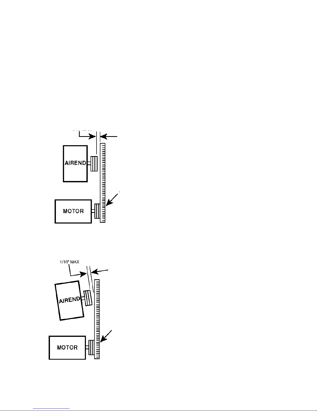
4.5 SHEAVE ALIGNMENT
Align Sheaves
Any degree of sheave misalignment will result in a
reduction of belt life. Misalignment of belt drive should
not exceed 1/16 in. (1.6 mm).
Parallel misalignment occurs when the drive and driven shafts are parallel, but the two sheaves lie in different planes (See Figure 4.5-1).
Angular misalignment occurs when the two shafts are
not parallel (See Figure 4.5-2).
1/16” (1.6mm) MAX
Ensure that the compressor is isolated from the
compressed air system by closing the isolation
valve and venting pressure from the drip leg.
Ensure that the main power disconnect switch is
locked and tagged.
An easy and effective method of checking alignment in
both directions between the driver and driven sheaves
utilizes an accurate straightedge.
Lay the straightedge across the face of the driver
(motor) sheave and check alignment of the driven
(airend) sheave.Then lay the straightedge across the
driven sheave and check that the driver sheave is
aligned.
Alignment should be within 1/16” (1.6 mm) maximum
when measuring the gap between the straightedge
and the rim of the opposite sheave in each direction.
This alignment is factory set and should only require
resetting if the drive motor or airend is removed.
The following steps should be taken to insure proper
alignment of all components.
STRAIGHTEDGE
FIGURE 4.5-1 PARALLEL MISALIGNMENT
1/16” (1.6mm) MAX
STRAIGHTEDGE
1. Remove the cooler box top panel.
2. Holding the straightedge against the front of the
airend sheave, measure the amount of misalignment
seen on the motor sheave. If misalignment is less than
1/16” (1.6 mm) then reinstall cooler box panel prior to
operating unit.
3. If misalignment is more than 1/16” (1.6 mm), the
motor sheave bushing must be loosened for repositioning.
To reposition the motor sheave:
1. Remove drive belts (See Section 4.6).
2. Remove the three hex head screws that hold the
sheave to the sheave bushing. See Figure 4.5-3.
3. Lubricate the thread and end of screws that were
just removed.
4. Reinstall all three screws in the holes of the bushing
that are threaded.
5. Slowly tighten the three screws evenly until the
sheave is pressed from the bushing. (Light tapping on
bushing may assist removal.)
FIGURE 4.5-2 ANGULAR MISALIGNMENT
6. Remove the screws from the holes.
19
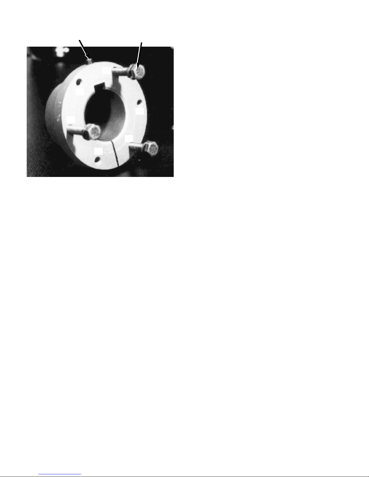
ALLEN HEAD SCREW
SHEAVE RETAINING SCREWS
A
4.6 DRIVE BELTS
Ensure that the compressor is isolated from the
compressed air system by closing the isolation
valve and venting pressure from the drip leg.
Ensure that the main power disconnect switch is
locked open and tagged.
B
B
A
A
B
“A” - Clearance Holes
“B” - Threaded Holes
FIGURE 4.5-3 MOTOR SHEAVE BUSHING
7. Loosen allen screw in sheave bushing.
8. Move the bushing either in or out on the motor shaft
depending upon the measurement taken earlier.
9.Tighten allen screw in sheave bushing.
10. Being careful to not move the bushing on the shaft,
align sheave so that the three threaded holes in the
sheave line up with the three clearance holes in the
bushing.
11. Insert all three screws through clearance holes in
the bushing and thread into sheave.
12. Slowly and evenly tighten all sheave retaining
screws.Torque to 108 lb-in. (1.2 kg-m).
13.Tap against large end of bushing using hammer
and block or sleeve to avoid damage. Continue to
torque screws until the specified wrench torque no
longer turns the screw after tapping.
14. Install belts as shown in Section 4.6.
If installing or removing the belts on a new unit at
startup, the motor support shipping bolt must first be
removed.This bolt is only used to secure the motor
support during shipment and will not be reinstalled
once the belts are put into place.
Locate the support shipping bolt as shown in Figure
2.7-1 and remove.
Replacement Parts
Belts (See Recommended Spare Parts Section 7.3).
Be sure to use only Ingersoll-Rand genuine parts to
assure proper belt size and length. Incorrectly sized
belts can lead to overloading of bearings and eventual
airend or motor failure.
Disassembly
Belt tension is maintained due to a pivoting motor
support.The weight of the motor holds the belt tight.
1. Remove the cooler box rear panel.
2. Carefully lift the back of the motor support and
place a block of wood underneath the motor support.
3. Remove belts from the airend sheave and the
motor sheave.
Installation / Inspection
Inspect sheave grooves for foreign material or rubber
build-up.Clean and degrease sheaves before
installing drive belts to insure long belt life.
1. Carefully lift the back of the motor support plate and
place a block of wood underneath the plate.
2. Install belts on the airend sheave and the motor
sheave.When installing a new belt, do not pry or force
the belt over the sheave grooves.
3. Remove the block of wood from under the motor
support.
15. Recheck for proper alignment.
16. Reinstall cooler box outer panel.
20
4.7 BELTTENSION
This unit has been designed with a unique self tensioning system for the drive belts.There is no adjustment required to insure proper belt tensioning. Be
sure to use only Ingersoll-Rand Genuine parts to
assure correct belt tension.
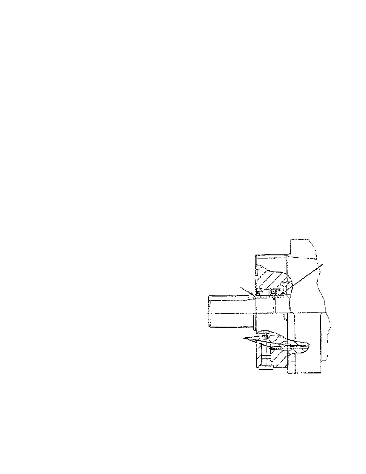
LIP EDGE
OF SEAL
INWARD
WEAR
SLEEVE
SCAVENGE
HOLES
4.8 SHAFT SEAL REPLACEMENT
There are two lip type seals on the compressor.They
are wearable parts and should be replaced at 8,000
hour intervals.While it is advisable to have your local
Ingersoll-Rand Distributor or Air Center perform this
work, the task can be accomplished by a good mechanic
following these instructions.
Before beginning any work on the compressor,
open, lock and tag the main electrical disconnect
and close the isolation valve on the compressor discharge.Wait 2 minutes after stopping to allow internal pressure to dissipate.Vent residual pressure
from the unit by slowly unscrewing the coolant fill
plug one turn. Unscrewing the fill plug opens a vent
hole, drilled In the plug, allowing the pressure to
release to atmosphere (See Figure 4.3-1). A slight
mist or oil droplets may be visible during venting.
Do not remove fill plug until all pressure has vented
from the unit. Also vent piping by slightly opening
the drip leg valve.When opening the drain valve or
removing the coolant fill plug, stand clear of the
valve discharge, wear work gloves and appropriate
eye protection.
SPECIAL TOOLS
A clean work bench
Seal installation tool
REPLACEMENT PARTS
Shaft seal kit
Seal retainer 0-Ring
Loctite® 609
Loctite® 515
Installation
1. Remove the cooler box rear panel.
2. Remove belts (See Section 4.6).
3. Remove the three hex lead screws that hold the
sheave to the sheave bushing (See Figure 4.5-3).
4. Lubricate the thread and end of screws that were just
removed.
5. Reinstall all three screws in the holes of the bushing
that are threaded.
6. Slowly tighten the three screws evenly until the
sheave is pressed from the bushing. (Light tapping on
bushing may assist removal.)
7. Remove the screws from the holes.
8. Loosen allen screw in sheave bushing.
9. Remove seal housing from airend assembly. Use
the removal slots provided to pry the seal housing
from the airend. Do not attempt to break the seal
housing loose by tapping.
10. Drive each seal out of the housing, being careful
not to damage the surface of the bore.The larger
double lip seal must be driven out toward the
inboard side.The term “inboard” side of the seal
housing will refer to the face that is mounted to the
airend assembly.The term “outboard” side will refer
to the face closest to the sheave.
11. Discard seals.
12. Remove check valve ball and plug from seal
housing.
13. Remove wear sleeve from shaft, being careful
not to damage the shaft.
14.Thoroughly clean the scavenge holes, (See
Figure 4.8-1), bore surfaces of the seal housing,
wear sleeve journal on the shaft, and the face of the
airend assembly.Be careful not to damage any of
the surfaces, and insure that no particles are
allowed to enter the bearings.
FIGURE 4.8-1 SHAFT SEAL ASSEMBLY
21
 Loading...