

Page 1

C.C.N. : 80445596 en
REV. : A
DATE : JULY 2009
Ingersoll Rand
X-IRI Communications Gateway
Operator’s Manual
Before installing or starting this unit for the first
time, this manual should be studied carefully to
obtain a working knowledge of the unit and or the
duties to be performed while operating and
maintaining the unit.
RETAIN THIS MANUAL WITH UNIT. This Technical
manual contains IMPORTANT SAFETY DATA and
should be kept with the unit at all times.
More Than Air. Answers.
Online answers: http://www.ingersollrandproducts.com
Page 2
2
SECTION 1 TABLE OF CONTENTS
SECTION 1 TABLE OF CONTENTS .............................2
SECTION 2 INTRODUCTION ...................................... 3
SECTION 3 SAFETY PRECAUTIONS .........................3
SAFETY PRECAUTIONS ............................................................3
INSTALLATION .............................................................................3
OPERATION ...................................................................................3
MAINTENANCE AND REPAIR .................................................4
SECTION 4 COMPRESSOR CONNECTION AND
CONTROL ......................................................................... 5
COMPRESSOR CONNECTION AND CONTROL ................ 5
INTELLISYS SOFTWARE REQUIREMENTS .......................... 5
MODBUS RTU ..............................................................................6
SECTION 5 INSTALLATION .......................................... 9
INSTALLATION .............................................................................9
UNIT LOCATION ..........................................................................9
POWER SUPPLY ...........................................................................9
DCS OR PLC CONNECTION ...................................................10
COMPRESSOR IRBUS CONNECTION ...............................10
DCS OR PLC COMMUNICATIONS .......................................11
COMPRESSOR COMMUNICATIONS: .................................11
OPERATIONAL INDICATIONS ...............................................11
RS485 NETWORK ....................................................................13
MODBUS ADDRESS SELECTION .........................................14
MODBUS PORT SETUP SELECTION ...................................15
GATEWAY SOFTWARE VERSION DISPLAY .......................16
COMMISSIONING PROCEDURE ..........................................17
SECTION 6 PARTS LIST ..............................................18
SECTION 7 TECHNICAL DATA ..................................18
SECTION 8 INTELLISYS MODBUS TABLES ............19
TABLE 1 SSR REDEYE CONTROLLER ...............................19
TABLE 2 SSR SG CONTROLLER .........................................22
TABLE 3 SSR SE 15100HP
CONTROLLER .............................................................................27
TABLE 4 SIERRA REDEYE 125200 HP
CONTROLLER .............................................................................30
TABLE 5 SIERRA SE 50100 HP
CONTROLLER .............................................................................33
TABLE 6 SIERRA SG 125400 HP
CONTROLLER .............................................................................36
TABLE 7 SSR SG CONTACT COOLED RETROFIT
CONTROLLER .............................................................................40
TABLE 8 RECIP REDEYE CONTROLLER ...........................45
TABLE 9 RECIP SG CONTROLLER .....................................49
TABLE 10 RECIP BOOSTER REDEYE
CONTROLLER .............................................................................53
TABLE 11 NIRVANA SGN CC CONTACT COOLED
CONTROLLER .............................................................................57
TABLE 12 NIRVANA SGNE CC CONTACT COOLED
CONTROLLER .............................................................................61
TABLE 13 NIRVANA SGNE OF OILFREE
CONTROLLER .............................................................................66
TABLE 14 SSR UP SE CONTROLLER .................................70
TABLE 15 ESA SE 22 150 KW
CONTROLLER .............................................................................73
TABLE 16 RSERIES S3 CONTROLLER .............................76
TABLE 17 NIRVANA 1530 KW 2040 HP DF
CONTROLLER .............................................................................78
Refer to Section Indicated
Note
Important or Caution, Safety
Page 3
SECTION 2 INTRODUCTION
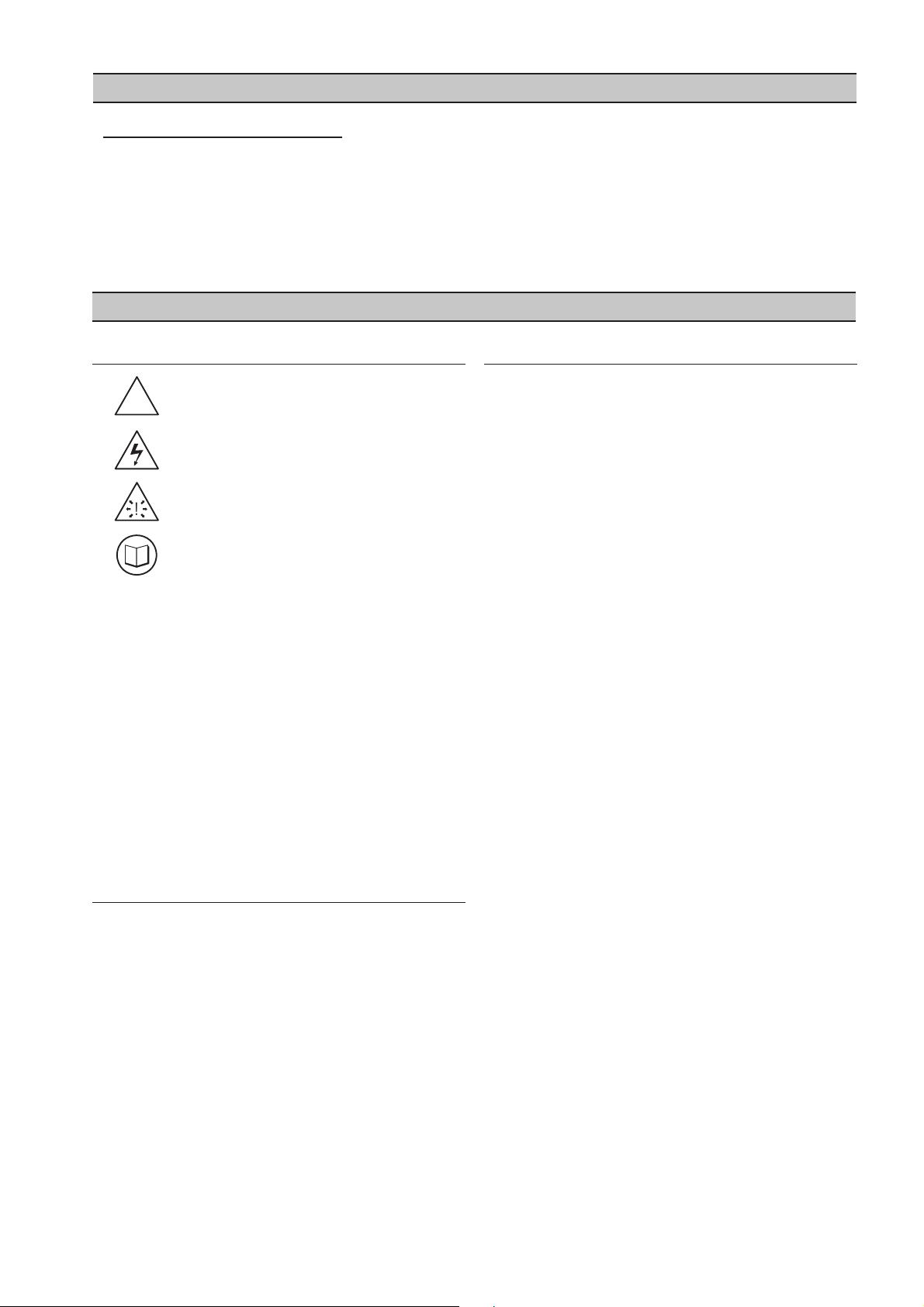
!
WARNING : Risk of Danger
WARNING : Risk of Electric Shock
!
WARNING : Risk of High Pressure
WARNING : Consult Manual
Before installing or operating theX-IRI GATEWAY, take
time to carefully read all the instructions contained
in this manual, all compressor manuals, and all
manuals of any other peripheral devices that may be
installed or connected to the unit.
Electricity and compressed air have the potential to
cause severe personal injury or property damage.
The operator should use common sense and good
working practices while operating and maintaining
this system. All applicable codes should be strictly
adhered to.
Maintenance must be performed by adequately
qualified personnel that are equipped with the
proper tools.
INSTALLATION
Installation work must only be carried out by a
competent person under qualified supervision.
A fused isolation switch must be fitted between the
main power supply and the product.
The X-IRI GATEWAY should be mounted in such a
location as to allow operational and maintenance
access without obstruction or hazard and to allow
clear visibility of indicators at all times.
If raised platforms are required to provide access
to the X-IRI GATEWAY, they must not interfere with
normal operation or obstruct access. Platforms and
stairs should be of grid or plate construction with
safety rails on all open sides.
•
•
•
•
•
•
•
•
OPERATION
The X-IRI GATEWAY must only be operated by
competent personnel under qualified supervision.
Never remove or tamper with safety devices, guards
or insulation materials fitted to the X-IRI GATEWAY.
The X-IRI GATEWAY must only be operated at
the supply voltage and frequency for which it is
designed.
When main power is switched on, lethal voltages are
present in the electrical circuits and extreme caution
must be exercised whenever it is necessary to carry
out any work on the unit.
Do not open access panels or touch electrical
components while voltage is applied unless it is
necessary for measurements, tests or adjustments.
Such work should be carried out only by a qualified
electrician equipped with the correct tools and
wearing appropriate protection against electrical
hazards.
All air compressors and/or other equipment
connected to the unit should have a warning sign
attached stating “THIS UNIT MAY START WITHOUT
WARNING” next to the display panel.
If an air compressor and/or other equipment
connected to the unit is to be started remotely,
attach two warning signs to the equipment stating
“THIS UNIT CAN BE STARTED REMOTELY”.
Attach one sign in a prominent location on the
outside of the equipment, and the other sign inside
the equipment control compartment.
•
•
•
•
•
•
•
The X-IRI Communication Gateway is designed to
in
terface the Intellisys Controllers on Ingersoll Rand
Compressors with a Distributed Control System (DCS),
Programmable Logic Controller (PLC), or any other
device that is capable of communicating using the
MODBUS RTU communications protocol.
SECTION 3 SAFETY PRECAUTIONS
SAFETY PRECAUTIONS
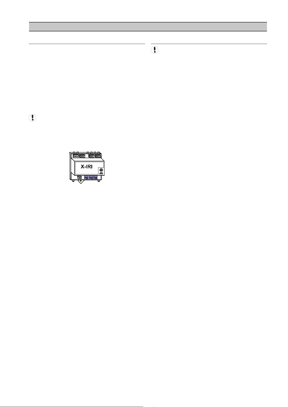
The X-IRI provides MODBUS connectivity to Ingersoll
Rand controllers that do not have built-in MODBUS
capability. The X-IRI also provides address filtering and
communication buffering capabilities to protect the
integrity of the serial data network.
The X-IRI is designed to be DIN Rail mounted within the
compressor control gear enclosure but can alternatively
be mounted remotely within a separate enclosure.
3
Page 4

MAINTENANCE AND REPAIR
M
aintenance, repairs or modifications must only
•
be carried out by competent personnel under
qualified supervision.
If replacement parts are required, use only genuine
•
parts from the original equipment manufacturer, or
an alternative approved source.
Carry out the following operations before opening
•
or removing any access panels or carrying out any
work on the X-IRI GATEWAY:
Isolate the X-IRI GATEWAY from the main
i.
electrical power supply. Lock the isolator in the
“OFF” position and remove the fuses.
Attach label to the isolator switch and to the
ii.
unit stating “WORK IN PROGRESS - DO NOT
APPLY VOLTAGE”. Do not switch on electrical
power or attempt to start the X-IRI GATEWAY if
such a warning label is attached.
Make sure that all instructions concerning
•
operation and maintenance are strictly followed
and that the complete unit, with all accessories and
safety devices, is kept in good working order.
The accuracy of sensor devices must be checked
•
on a regular basis. They must be calibrated when
acceptable tolerances are exceeded. Always ensure
any pressure within the compressed air system is
safely vented to atmosphere before attempting to
remove or install a sensor device.
•
The X-IRI GATEWAY must only be cleaned with a
damp cloth, using mild detergents if necessary.
Avoid the use of any substances containing
corrosive acids or alkalis.
Do not paint the control faceplate or obscure any
•
indicators, controls, instructions or warnings.
4
Page 5
SECTION 4 COMPRESSOR CONNECTION AND CONTROL
Setting a MODBUS polling rate of less than 500
milliseconds will not cause a quicker response from X-IRI.
The PLC or DCS communicates to the X-IRI Gateway via
a two wire, RS-485 network utilizing the MODBUS RTU
protocol.
The X-IRI Gateway module is installed within the
compressor control cabinet and connected to the PLC or
DCS using Belden 9841 or equivalent RS-485 cable.
INTELLISYS SOFTWARE REQUIREMENTS
Each Intellisys controller must have its controller
software revision at or above a certain minimum level
to work with the IRI.
The machine types and required software EPROM
minimum version levels are listed below. Check the
machine to be connected to an IRI for the appropriate
EPROM. If the EPROM is not of the correct minimum
version level, the appropriate EPROM may be ordered
from your local Ingersoll Rand Distributor or Air Center.
Machine Type EPROM Minimum Version Level
SSR 50-450 Horsepower - 1 stage (Red Eye) 2.3
SSR 50-450 Horsepower - 2 stage (Red Eye) 2.3
SSR SG 1.0
15-50 Horsepower 1.4
Sierra 50-100 Horsepower (SE) 1.2
Sierra 100-200 Horsepower (Red Eye) 2.5
Sierra 125-400 HP SG 1.0
Recip (Red Eye) 1.6
Recip SG 1.0
Nirvana SGN 1.0
Nirvana SGNe CC 2.0
Nirvana SGNe OF 1.0
Pegasus 1.0
ESA SE 22-150 KW 1.6
When monitoring compressor data only, no options
are required to be installed in the Intellisys controller. If
machine control is desired, the Remote Start/Stop and
Sequence options must be installed and turned “On”.
COMPRESSOR CONNECTION AND CONTROL
T
he X-IRI Gateway module is designed to interface to
any Ingersoll Rand Intellisys controlled compressor. All
Ingersoll Rand compressors equipped with Intellisys
controllers must use this interface when communicating
with MODBUS masters.
The X-IRI gateway prevents the compressor controller
from seeing any communications that aren’t directed
toward the controller’s network address. Additionally, the
X-IRI will buffer communications so that the compressor
controller will not receive a command greater than once
every 500 milliseconds.
5
Page 6
MODBUS RTU
A pause longer than 1.5 byte-times will render the
message invalid and it will be ignored.
Message data format is dependent on function and will
consist of a combination of the following elements:
1) Destination address (slave network address)
2) Function Code
3) Data start address (slave register start address)
4) Number of registers, number of bytes of data
5) Message data
6) CRC checksum
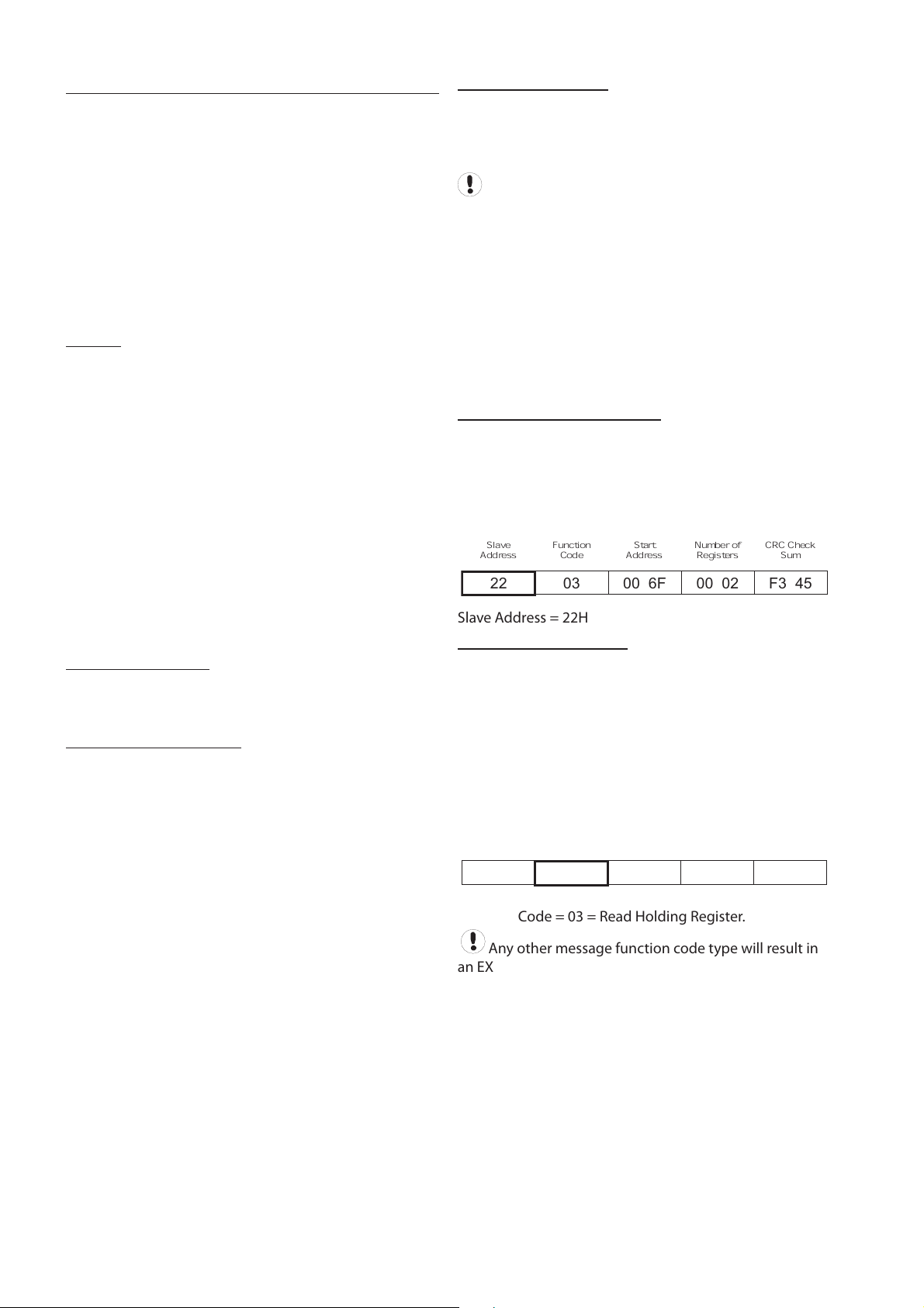
Message Destination Address
The ‘destination address’ must be correct for the ‘slave’
controller device for which the message is intended. An
address can be from 1 to 127 decimal (01Hex to 7FHex).
The SMG Box is transparent and addresses must be for the
destination ‘slave’ controller or unit. Each controller or unit
must be set with a unique address.
Slave
Address
Function
Code
Start
Address
Number of
Registers
CRC Check
Sum
22 03 00 6F 00 02 F3 45
Slave Address = 22Hex = 34 Decimal
Message Function Codes
The message function code defines the required data
processing operation of the slave controller. Although
several types of message function codes are defined by
the MODBUS standard, only the message function code
types working directly with registers are implemented on
controller units:
03H Read Holding Register(s) – Read
06H Preset Single Register - Write
Slave
Address
Function
Code
Start
Address
Number of
Registers
CRC Check
Sum
22 03 00 6F 00 02 F3 45
Function Code = 03 = Read Holding Register.
Any other message function code type will result in
an EXCEPTION response.
This document discusses generic MODBUS
communications and how to implement the software
specific ‘MODBUS Table’ information. MODBUS
communication formatting may differ from controller to
controller and you may require more than one ‘MODBUS
Table’.
Always check the software variant identification and
version number for a controller with the variant and
version of the ‘MODBUS Table’ supplied. In some instances
the information contained in a ‘MODBUS Table’ may not
be applicable to a controller installed with the same
software variant but a different version number.
General
MODBUS RTU (Remote Terminal Unit) is a master-slave
type protocol. An Intellisys Controller functions as the
slave device. Information requests or commands are
communicated from master to slave only through the
X-IRI.
The X-IRI will always respond to communications from a
remote master device in accordance with the MODBUS
RTU protocol standard.
The MODBUS protocol is used to communicate with
personal computers (PC), Programmable Logic Controllers
(PLC’s), or Distributed Control Systems (DCS) over the
Network port. The X-IRI only responds to two MODBUS
commands, Read Holding Register 03 (03 Hex) and Preset
Single Register 06 (06 Hex). (See Modicon MODBUS
Protocol Reference Guide, PI-MBUS-300 Rev. J or later, for
more details on MODBUS).
Communication Link
MODBUS is implemented using a two-wire RS485
industry standard communications link operating in
master-slave mode.
RS485 Serial Data Format
The RS485 MODBUS port is a 2-wire operating with an
asynchronous serial data format: 8 data bits / no parity / 1
or 2 stop bits (8,N,1 or 8,N,2) - transmitted at 9600 baud.
Message Data Format
The bytes of the MODBUS RTU message must be sent
in one message package. The RTU protocol allows for a
maximum pause of 1.5 byte-times between 2 consecutive
bytes of a message.
6
Page 7
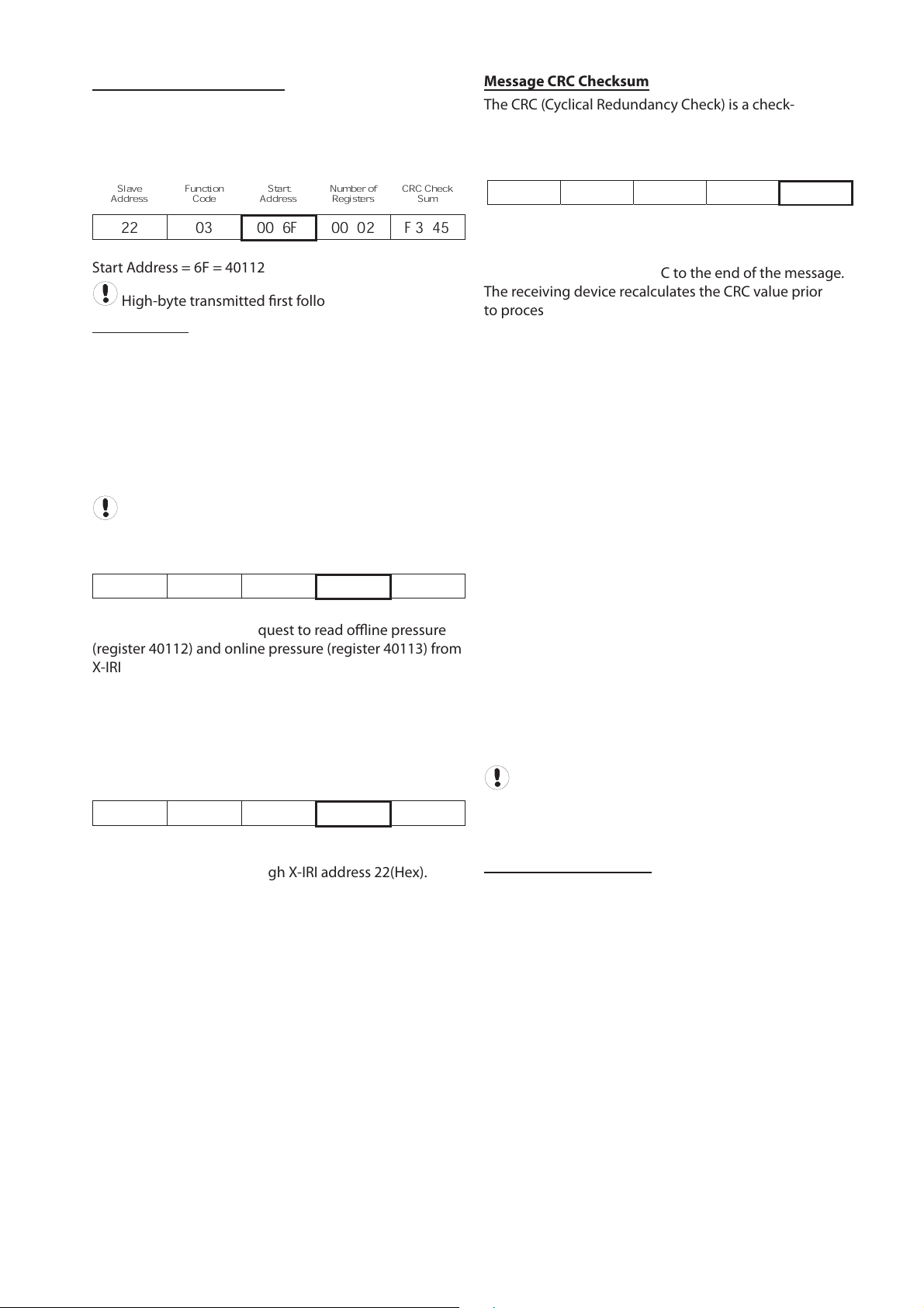
Message Data Start Address
Slave
Address
Function
Code
Start
Address
Number of
Registers
CRC Check
Sum
22 03 00 6F 00 02 F3 45
Start Address = 6F = 40112
High-byte transmitted first followed by low-byte.
Message Data
The message data content depends on the message
function code type.
03H Read Holding Register(s)
The Number of Registers designates the 16bit integer
value that determines the size (in 16bit ‘word’ registers)
of the message data being requested. This is the number
of 16bit registers to read. This information is contained in
the ‘MODBUS Table’.
A maximum of 32 registers can be read at one time.
Slave
Address
Function
Code
Start
Address
Number of
Registers
CRC Check
Sum
22 03 00 6F 00 02 F3 45
The example above is a request to read offline pressure
(register 40112) and online pressure (register 40113) from
X-IRI address 22(Hex)
06H Preset Single Register
The Data byte 0 byte 1 designates the value of the 16bit
integer word to be written to the Intellisys controller. This
information is contained in the ‘MODBUS Table’.
Slave
Address
Function
Code
Start
Address
DATA
byte 0 byte 1
CRC Check
Sum
22 06 00 6F 00 5F FE BC
The example above is a request to set offline pressure
(register 40112) to 95 through X-IRI address 22(Hex).
Message CRC Checksum
The CRC (Cyclical Redundancy Check) is a check-sum
generated by means of ‘A001H polynomial’.
Slave
Address
Function
Code
Start
Address
DATA
byte 0 byte 1
CRC Check
Sum
22 06 00 6F 00 5F FE BC
The CRC is two bytes containing a 16-bit binary value
(word). The CRC value is calculated by the transmitting
device that appends the CRC to the end of the message.
The receiving device recalculates the CRC value prior
to processing of a received message and compares the
result to the actual CRC value appended to the message.
If the two values do not match the message is regarded
as invalid.
The CRC is initiated by first preloading a 16bit register
to all 1’s (FFFF Hex). Then a process begins of applying
each consecutive 8bit byte of the message to the register
contents using an exclusive ‘OR’ calculation. The result is
shifted one bit in the direction of the least significant bit
(LSB), with the most significant bit (MSB) set at ‘0’. The LSB
is then examined; if ‘1’ the register content is applied to
the polynomial value ‘A001’ Hex (1010 0000 0000 0001)
using an exclusive ‘OR’ calculation - if ‘0’ no exclusive OR
takes place.
This process is repeated until eight ‘bit’ shifts have
been performed. After the eighth bit shift, the next 8bit
message byte is applied to the register contents using an
exclusive ‘OR’ calculation. The bit shift and re-calculation
process is then repeated again. When all message bytes
have been processed the final content of the 16bit
register is the message CRC value.
Only the 8bits of ‘data’ in each message character is used
for generating the CRC; start, stop and parity bits are
ignored.
When the 16bit CRC value is appended to a message,
the low order byte must be transmitted first followed by
the high order byte. An incorrect or byte reversed check
sum will render the message invalid and it will be ignored.
Slave Response Timeout
A slave controller may not answer immediately. Ensure
the ‘slave timeout’ setting of the ‘master’ device is set
to a value no less than 500ms. If the ‘slave’ device fails
to receive a valid message due to a communication
disruption, parity error, CRC error or other reasons, no
response is given and the master must process a timeout
condition in this instance. If the ‘slave’ receives a valid
message that cannot be processed an exception response
will be returned.
T
he message data start address (16bit word) designates
the initial register address location in the controller from
which the data is processed. Start address information is
contained in the ‘MODBUS Table’.
7
Page 8
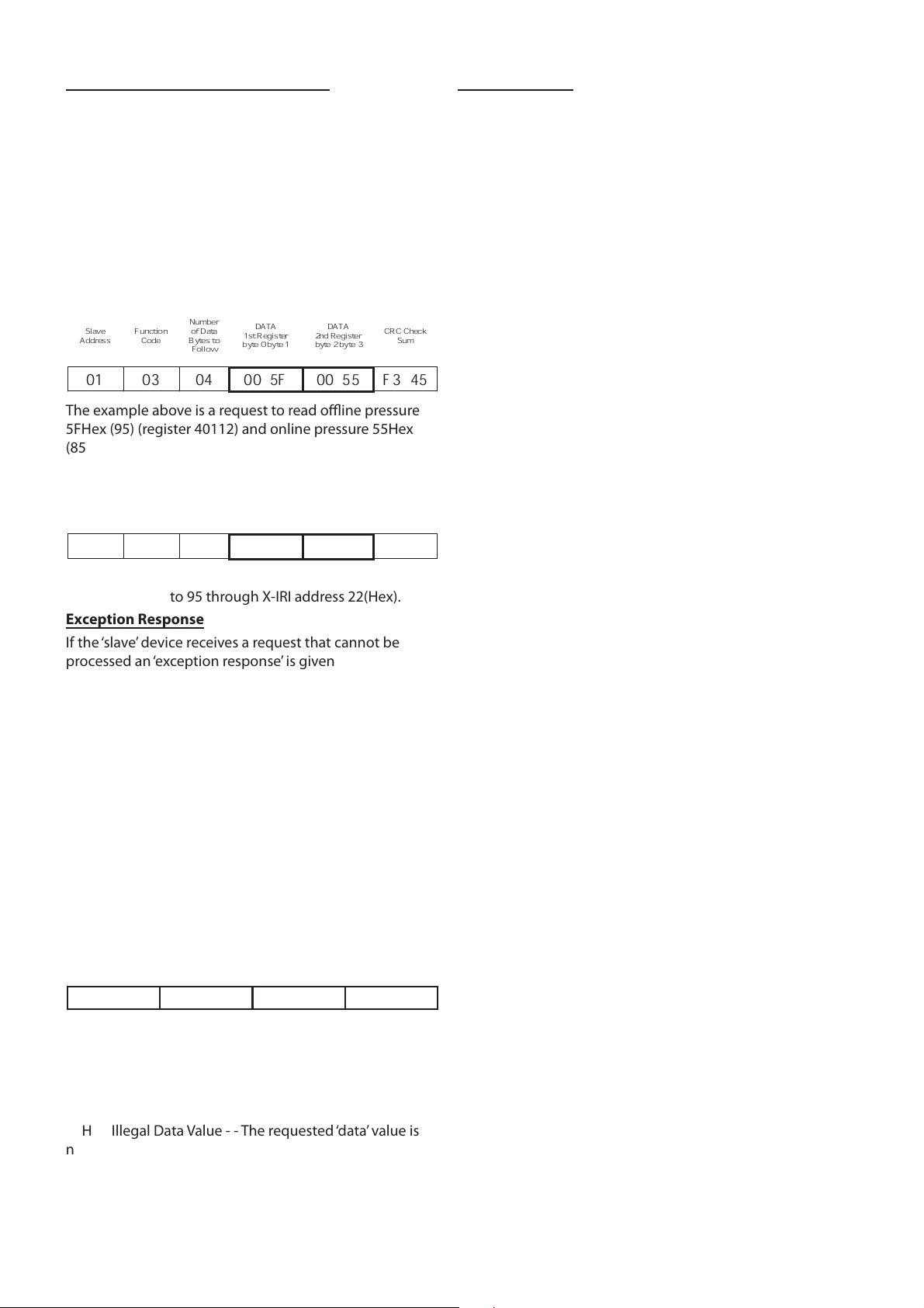
Message Answer From Slave to Master
Slave
Address
Function
Code
Number
of Data
Bytes to
Follow
DATA
1st Register
byte 0 byte 1
DATA
2nd Register
byte 2 byte 3
CRC Check
Sum
01 03 04 00 5F 00 55 F3 45
The example above is a request to read offline pressure
5FHex (95) (register 40112) and online pressure 55Hex
(85) (register 40113) from X-IRI address 22(Hex).
06Hex - Preset Single Register
Slave
Address
Function
Code
Number
of Data
Bytes to
Follow
DATA
1st Register
byte 0 byte 1
DATA
2nd Register
byte 2 byte 3
CRC Check
Sum
01 03 04 00 5F 00 55 F3 45
The example above is a request to set offline pressure
(register 40112) to 95 through X-IRI address 22(Hex).
Exception Response
If the ‘slave’ device receives a request that cannot be
processed an ‘exception response’ is given. An exception
response message consists of the following elements:
Slave Network Address (1 byte): Slave address
identification
Function Code (1 byte): In a normal response, the
slave repeats the function code of the original
master request. All function codes have an MSB
(most significant bit) of 0 (values are all below 80
hexadecimal). In an exception response, the slave
sets the MSB of the function ‘code’ to 1. This makes
the ‘code’ value 80 Hex greater than the received
‘code’ value from the master.
Data (1 byte): The ‘data’ response will contain a ‘1
byte’ value exception code.
CRC Checksum (2 byte).
01 90 04 4D C3
CRC Check SumSlave Address Function Code Error Code
Exception Codes:
01H Illegal Function Code - - The requested ‘code’
function is not supported.
02H Illegal Data Address - - The requested ‘data start
address’ is not supported.
03H Illegal Data Value - - The requested ‘data’ value is
not supported.
04H Function Error - - The slave cannot execute the
request or the request type is inhibited.
•
•
•
•
Troubleshooting
Problem:
No ‘slave’ response or corrupt MODBUS message
Solution:
Check that the ‘slave’ controller is set for the
anticipated slave address
Check that all ‘slave’ controllers are set with a unique
system address
Check that the controller is set for MODBUS RTU
mode (if applicable)
Check that the ‘master’ is operating in MODBUS RTU
mode
Check that the ‘master’ baud rate, parity bit and
number of stop bits are correct
Check that the ‘master ‘response timeout is set for a
minimum of 500ms
Check that the ‘master’ is implementing the specified
CRC check sum process
Check RS485 wiring polarity and security of
connections
Problem:
Last character of MODBUS message is corrupted
Solution:
Add a delay of 2ms after last character received
before releasing RTS signal
Problem:
The MODBUS master message is reflected in the
slave answer
Solution:
Inhibit RX/TX echo on ‘master’ device
communications port
•
•
•
•
•
•
•
•
•
•
•
•
•
T
he format of the ‘slave’ controller answer is similar to the
original master request format; the message data content
depends on the message function code type.
The ‘address’ and ‘code’ of the slave answer is identical
to the original request message; the address is the ‘slave’
device address and the ‘code’ is a repeat of received
function code type from the master. The remainder of the
message is dependent on the requested function code
type. The CRC checksum is re-calculated for the answer
message characters using the specified CRC process.
03H Read Holding Register(s)
8
Page 9
SECTION 5 INSTALLATION
It is recommended that installation and
commissioning be carried out by an authorized and
trained product supplier.
L
E
D
#
6
L
E
D
#
7
L
E
D
#
8
L
E
D
#
9
s
c
r
e
e
n
L
2
L
1
12 13 23
Multi485
X05
s
c
r
e
e
n
L
2
L
1
12 13 23
MODBUS
X03
1 2
+
2
4
V
a
c
/
d
c
0
V
a
c
/d
c
X01
X02
X04
L
E
D
#
1
2
3
4
1
ON
OFF
6
7
8
5
1
0
1
1
1
2
9
SW1 SW2 SW3
L
E
D
#
2
L
E
D
#
3
L
E
D
#
5
L
E
D
#
4
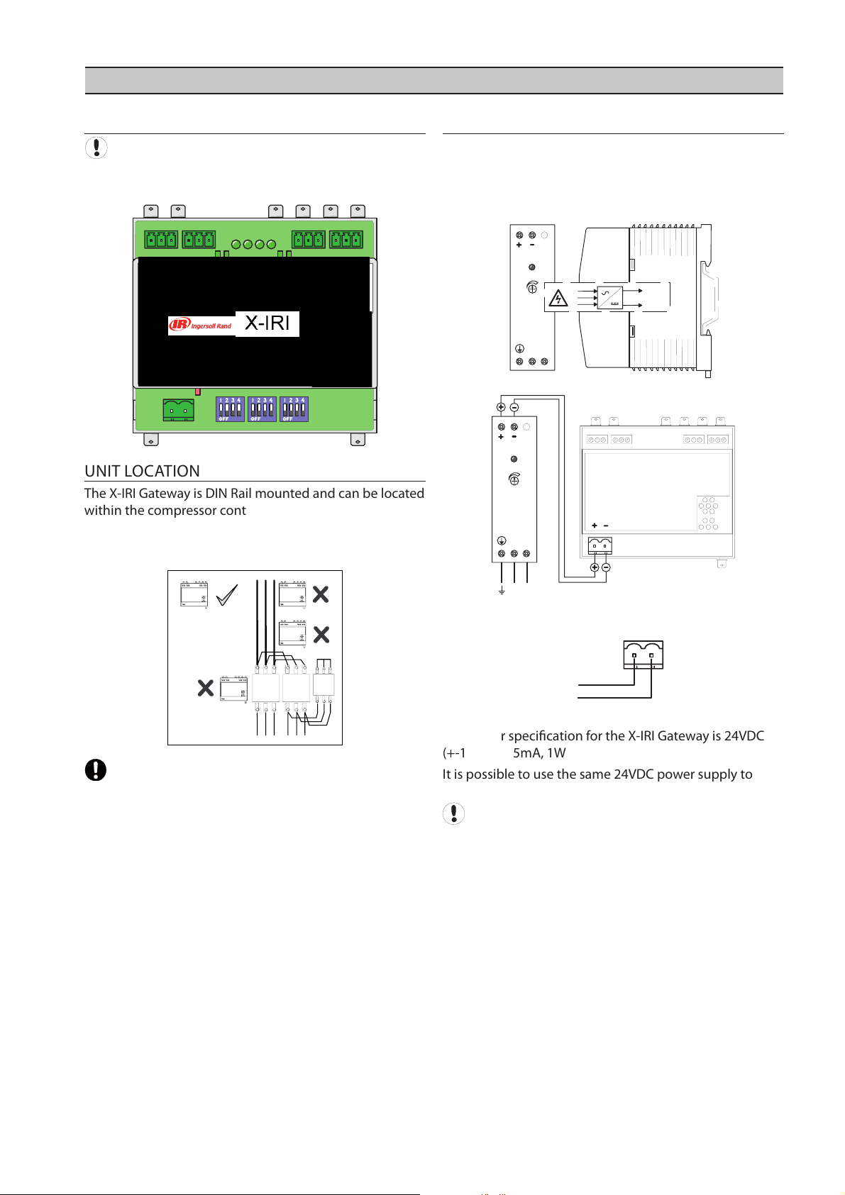
Avoid mounting the X-IRI Gateway near high voltage
cables, high voltage devices or equipment or motor
starter contactors.
POWER SUPPLY
The X-IRI Gateway is powered by an external 24VDC
power supply. The AC supply voltage for the 24VDC
power supply is derived from the compressor’s 110VAC or
230VAC internal AC supply.
DC
+V.ADJ
LN
24V DC
100-240VAC
50/
60Hz
E
N
L
0VDC
+24VDC
1
2
X01
GATEWAY
LN
DC
+V.ADJ
L
N
24V DC
100-240VAC
50/60Hz
24V
AC/DC
X01
1 2
+24VDC
0VDC
+
-
The power specification for the X-IRI Gateway is 24VDC
(+-10%) @ 35mA, 1W
It is possible to use the same 24VDC po
wer supply to
power multiple X-IRI Gateway devices.
Wire polarity is important
INSTALLATION
UNIT LOCATION
The X
-IRI Gateway is DIN Rail mounted and can be located
within the compressor control enclosure or remotely
within a separate enclosure. X-IRI Gateway must be
located within 1000ft (10m) of the compressor controller.
9
Page 10
DCS OR PLC CONNECTION
Wire polarity is important
Use 2-wire, 24 gauge (Belden 9841 or equivalent), twisted
pair, earth shielded, data cable with a total system
network length no greater than 4000ft (1219m).
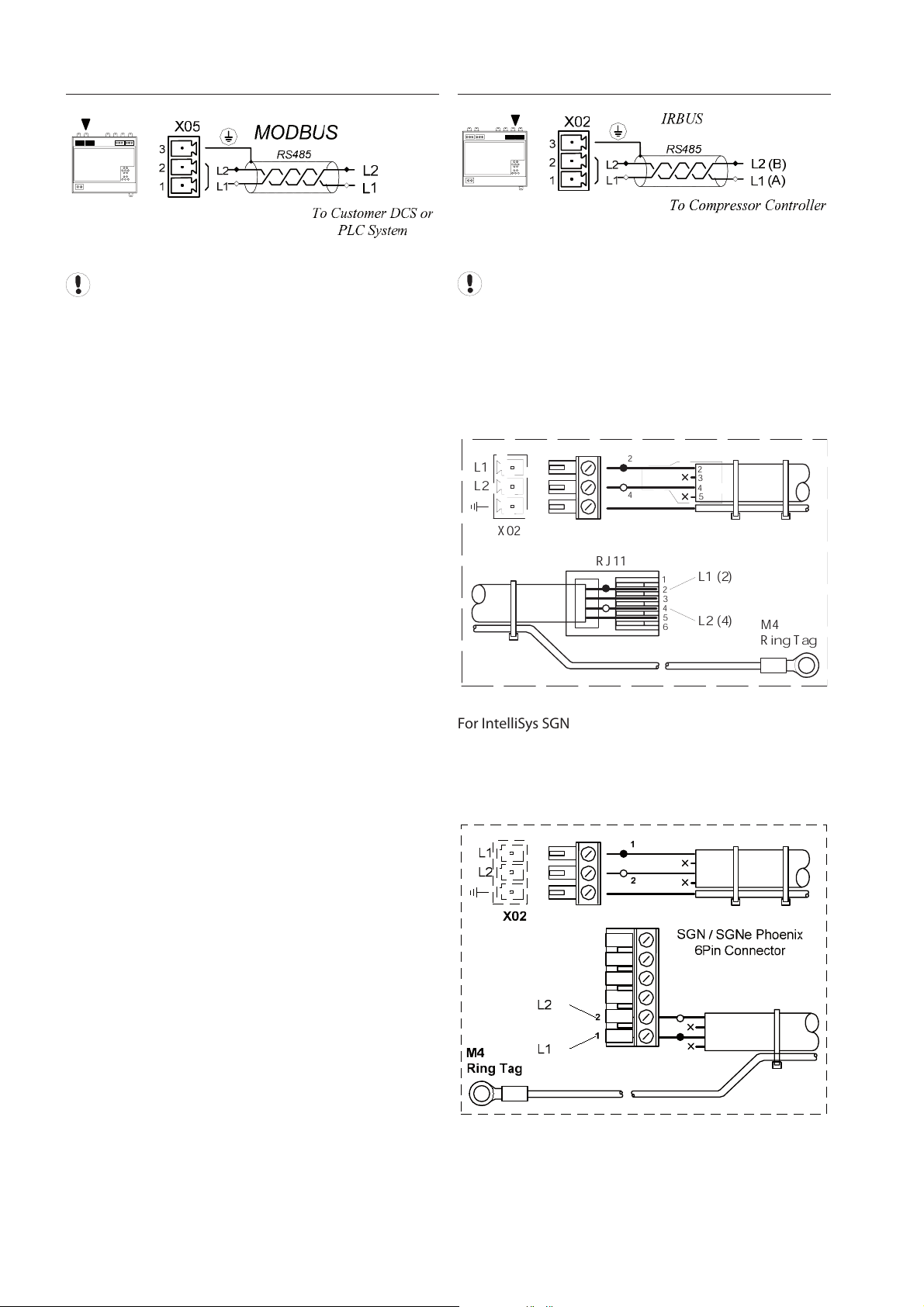
COMPRESSOR IRBUS CONNECTION
1
6
2
3
5
4
RJ11
2
4
3
5
L1
L2
M4
Ring Tag
L1 (2)
L2 (4)
2
4
X02
For IntelliSys SGN, SGNe and Nirvana 15-30kW (20-40HP)
equipped with a Phoenix RS-485 data communications
connector, use the RJ11 Modbus cable supplied with the
X-IRI Gateway and modify as shown by removing the RJ11
Plug.
Wire polarity is important
Use 2-
wire, 24 gauge (Belden 9841 or equivalent), twisted
pair, earth shielded, data cable with a length no greater
than 1000ft (10m).
For IntelliSys “Red Eye”, SG and SE equipped with an RJ11
RS-485 data communications connection port, use the
RJ11 Modbus cable supplied with the X-IRI Gateway.
10
Page 11
11
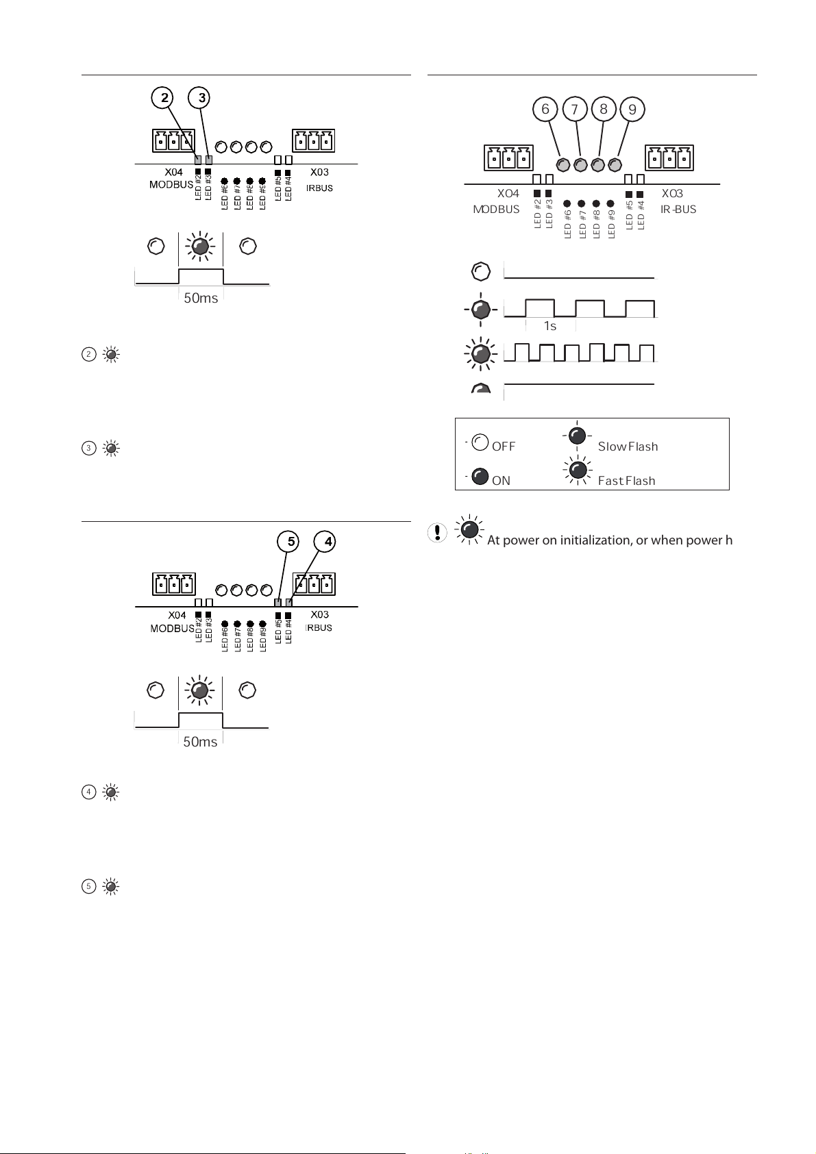
DCS OR PLC COMMUNICATIONS
50ms
RX – Data Received:
2
A valid MODBUS communication has just been
received from the DCS or PLC unit. In normal operation
this event should occur periodically depending on the
polling rate.
TX – Data Transmitted:
3
A MODBUS broadcast or message has just been
sent. To keep the link active, a MODBUS message must be
sent at least once every 10 seconds.
COMPRESSOR COMMUNICATIONS:
50ms
RX – Data Received:
4
A valid IRBUS communication has just been
received from the compressor controller. In normal
operation this event should occur at least once every ½
second.
TX – Data Transmitted:
5
An IRBUS message has just been sent to the
compressor controller. In normal operation this event
should occur at least once every ½ second.
OPERATIONAL INDICATIONS
OFF Slow Flash
ON Fast Flash
L
E
D
#
6
L
E
D
#
7
L
E
D
#
8
L
E
D
#
9
Multi485
X04
L
E
D
#
2
L
E
D
#
3
L
E
D
#
5
L
E
D
#
4
MODBUS
X03
7
6
9
8
1s
MODBUS IR-BUS
At power on initialization, or when power has
been removed, all operational indicators will fast flash for
several seconds.
Page 12
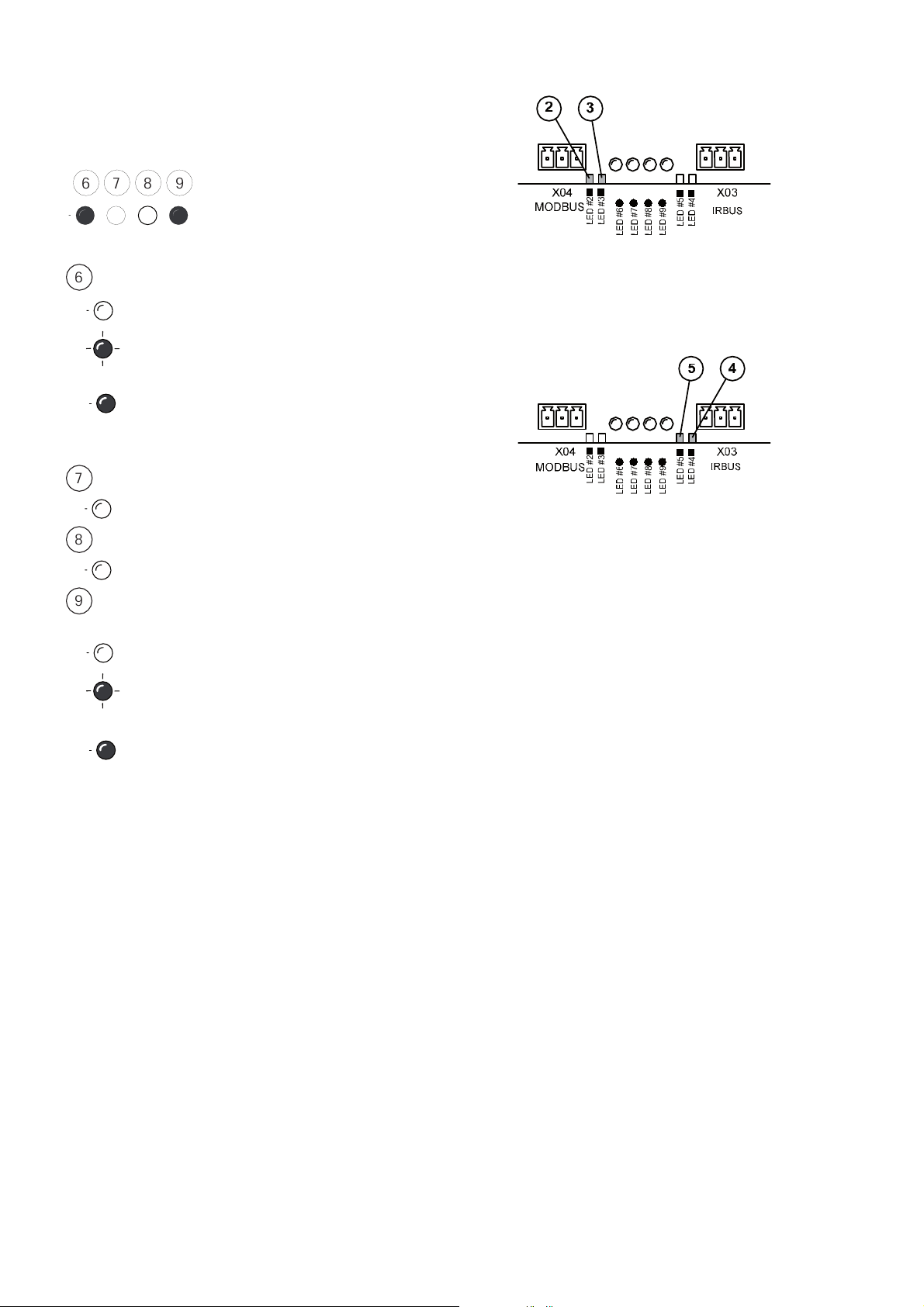
Normal O
6 7 8 9
Normal operation function:
6
Modbus Communications with MODBUS master.
OFF
No valid communications with a MODBUS
master
ON: Valid communication with a MODBUS
master, at least one read/write operation once
every 10 seconds.
7
No function
Always OFF: no other defined function
8
No function
Always OFF: no other defined function
9
IR-BUS communication with a compressor
controller
OFF
No valid communications with the compressor
controller.
ON: IR-BUS compressor controller detected and
communication link established.
Led#2: Every flash indicates reception of a valid MODBUS
messsage from the MODBUS master.
Led#3: Every flash indicates transmission of a valid
MODBUS messsage to the MODBUS master.
Led#5: Every flash indicates transmission of a valid IRBUS
messsage to the IR-BUS compressor controller.
Led#4: Every flash indicates reception of a valid IR-BUS
message from the IR-BUS compressor controller.
peration Example:
When there is valid communication with a MODBUS
master and an IR-BUS compatible compressor controller
the main operation indicators will light up as shown
below.
12
Page 13
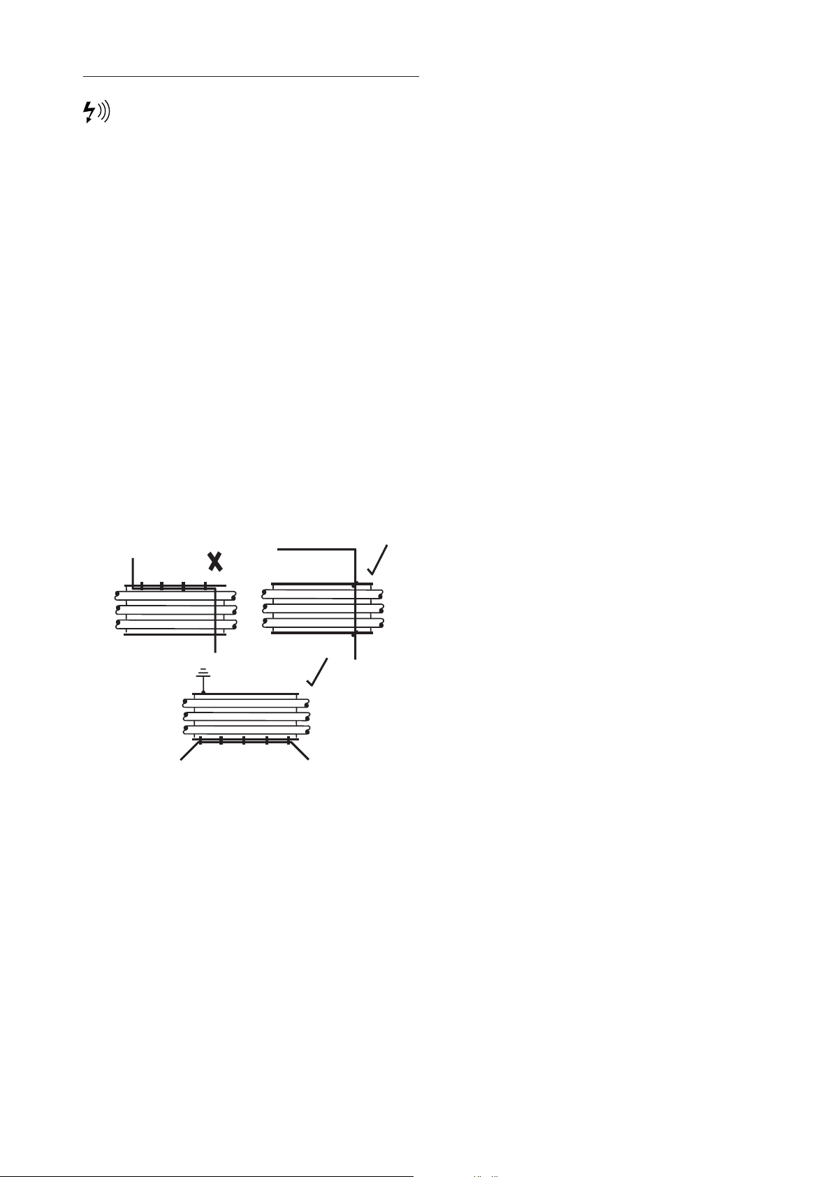
RS485 NETWORK
RS-485 data communications and other low
voltage signals can be subject to electrical interference.
This potential can result in intermittent malfunction
or anomaly that is difficult to diagnose. To avoid this
possibility always use earth shielded cables, securely
bonded to a known good earth at one end. In addition,
give careful consideration to cable routing during
installation.
1) Never route an RS-485 data communications or low
voltage signal cable alongside a high voltage 3-phase
power supply cable. If it is necessary to cross the path of a
power supply cable(s), always cross at a right angle.
2) If it is necessary to follow the route of power supply
cables for a short distance (for example: from a
compressor unit to a wall along a suspended cable tray)
attach the RS- 485 or signal cable on the outside of an
earthed cable tray such that the cable tray forms an
earthed electrical interference shield.
3) Where possible, never route an RS-485 or signal cable
near to equipment or devices that may be a source of
electrical interference (for example: 3-phase power
supply transformer, high voltage switchgear unit,
frequency inverter drive module, radio communications
antenna).
13
Page 14
14
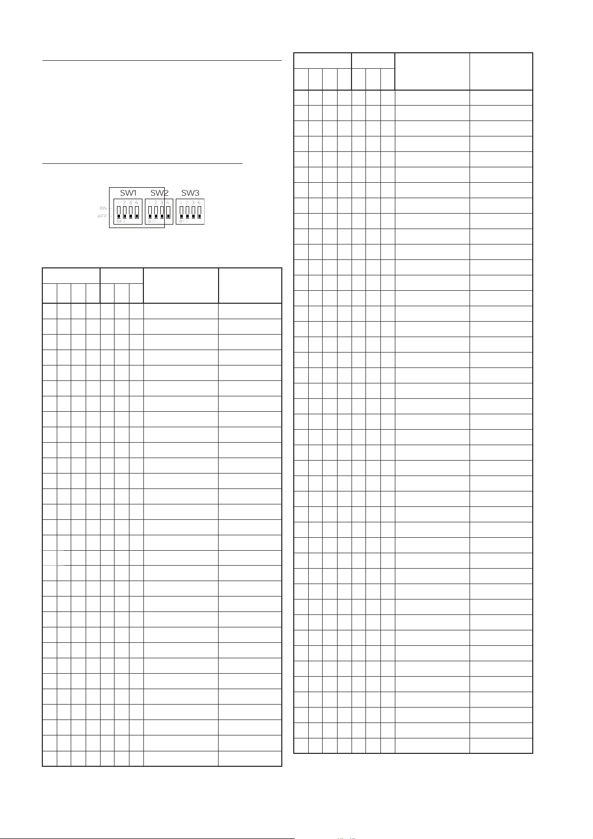
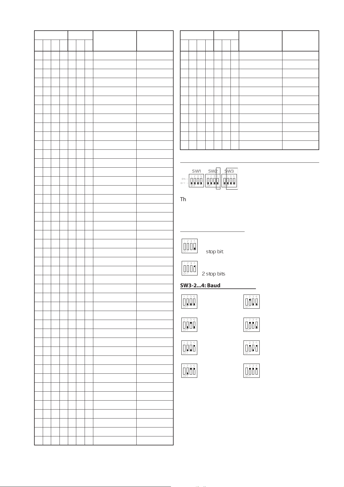
MODBUS ADDRESS SELECTION
Each compressor connected to the MODBUS network will
have a unique assigned address, starting at compressor
1 increasing sequentially to the number of compressors
connected to the MODBUS network. The MODBUS
address is selected by using DIP switches 1, 2, 3, and 4
on SW1, and switches 1, 2, and 3 on SW2 on the X-IRI
Gateway.
SW1, 1 to4 and SW2, 1 to 3: Address Selection
The addresses are selected as shown in the following
table: (Note: ON = 1, OFF = 0 )
SW1 SW1 MODBUS
Address
(Decimal)
MODBUS
Address
(Hexl)1 2 3 4 1 2 3
0 0 0 0 0 0 0 1 1
1 0 0 0 0 0 0 1 1
0 1 0 0 0 0 0 2 2
1 1 0 0 0 0 0 3 3
0 0 1 0 0 0 0 4 4
1 0 1 0 0 0 0 5 5
0 1 1 0 0 0 0 6 6
1 1 1 0 0 0 0 7 7
0 0 0 1 0 0 0 8 8
1 0 0 1 0 0 0 9 9
0 1 0 1 0 0 0 10 A
1 1 0 1 0 0 0 11 B
0 0 1 1 0 0 0 12 C
1 0 1 1 0 0 0 13 D
0 1 1 1 0 0 0 14 E
1 1 1 1 0 0 0 15 F
0 0 0 0 1 0 0 16 10
1 0 0 0 1 0 0 17 11
0 1 0 0 1 0 0 18 12
1 1 0 0 1 0 0 19 13
0 0 1 0 1 0 0 20 14
1 0 1 0 1 0 0 21 15
0 1 1 0 1 0 0 22 16
1 1 1 0 1 0 0 23 17
0 0 0 1 1 0 0 24 18
1 0 0 1 1 0 0 25 19
0 1 0 1 1 0 0 26 1A
1 1 0 1 1 0 0 27 1B
0 0 1 1 1 0 0 28 1C
1 0 1 1 1 0 0 29 1D
SW1 SW1
MODBUS
Address
(Decimal)
MODBUS
Address
(Hexl)
1 2 3 4 1 2 3
0 1 1 1 1 0 0 30 1E
1 1 1 1 1 0 0 31 1F
0 0 0 0 0 1 0 32 20
1 0 0 0 0 1 0 33 21
0 1 0 0 0 1 0 34 22
1 1 0 0 0 1 0 35 23
0 0 1 0 0 1 0 36 24
1 0 1 0 0 1 0 37 25
0 1 1 0 0 1 0 38 26
1 1 1 0 0 1 0 39 27
0 0 0 1 0 1 0 40 28
1 0 0 1 0 1 0 41 29
0 1 0 1 0 1 0 42 2A
1 1 0 1 0 1 0 43 2B
0 0 1 1 0 1 0 44 2C
1 0 1 1 0 1 0 45 2D
0 1 1 1 0 1 0 46 2E
1 1 1 1 0 1 0 47 2F
0 0 0 0 1 1 0 48 30
1 0 0 0 1 1 0 49 31
0 1 0 0 1 1 0 50 32
1 1 0 0 1 1 0 51 33
0 0 1 0 1 1 0 52 34
1 0 1 0 1 1 0 53 35
0 1 1 0 1 1 0 54 36
1 1 1 0 1 1 0 55 37
0 0 0 1 1 1 0 56 38
1 0 0 1 1 1 0 57 39
0 1 0 1 1 1 0 58 3A
1 1 0 1 1 1 0 59 3B
0 0 1 1 1 1 0 60 3C
1 0 1 1 1 1 0 61 3D
0 1 1 1 1 1 0 62 3E
1 1 1 1 1 1 0 63 3F
0 0 0 0 0 0 1 64 40
1 0 0 0 0 0 1 65 41
0 1 0 0 0 0 1 66 42
1 1 0 0 0 0 1 67 43
0 0 1 0 0 0 1 68 44
1 0 1 0 0 0 1 69 45
0 1 1 0 0 0 1 70 46
1 1 1 0 0 0 1 71 47
0 0 0 1 0 0 1 72 48
SW1
SW2 SW3
Page 15
15
SW1 SW1
MODBUS
Address
(Decimal)
MODBUS
Address
(Hexl)1 2 3 4 1 2 3
1 0 0 1 0 0 1 73 49
0 1 0 1 0 0 1 74 4A
1 1 0 1 0 0 1 75 4B
0 0 1 1 0 0 1 76 4C
1 0 1 1 0 0 1 77 4D
0 1 1 1 0 0 1 78 4E
1 1 1 1 0 0 1 79 4F
0 0 0 0 1 0 1 80 50
1 0 0 0 1 0 1 81 51
0 1 0 0 1 0 1 82 52
1 1 0 0 1 0 1 83 53
0 0 1 0 1 0 1 84 54
1 0 1 0 1 0 1 85 55
0 1 1 0 1 0 1 86 56
1 1 1 0 1 0 1 87 57
0 0 0 1 1 0 1 88 58
1 0 0 1 1 0 1 89 59
0 1 0 1 1 0 1 90 5A
1 1 0 1 1 0 1 91 5B
0 0 1 1 1 0 1 92 5C
1 0 1 1 1 0 1 93 5D
0 1 1 1 1 0 1 94 5E
1 1 1 1 1 0 1 95 5F
0 0 0 0 0 1 1 96 60
1 0 0 0 0 1 1 97 61
0 1 0 0 0 1 1 98 62
1 1 0 0 0 1 1 99 63
0 0 1 0 0 1 1 100 64
1 0 1 0 0 1 1 101 65
0 1 1 0 0 1 1 102 66
1 1 1 0 0 1 1 103 67
0 0 0 1 0 1 1 104 68
1 0 0 1 0 1 1 105 69
0 1 0 1 0 1 1 106 6A
1 1 0 1 0 1 1 107 6B
0 0 1 1 0 1 1 108 6C
1 0 1 1 0 1 1 109 6D
0 1 1 1 0 1 1 110 6E
1 1 1 1 0 1 1 111 6F
0 0 0 0 1 1 1 112 70
1 0 0 0 1 1 1 113 71
0 1 0 0 1 1 1 114 72
1 1 0 0 1 1 1 115 73
0 0 1 0 1 1 1 116 74
SW1 SW1
MODBUS
Address
(Decimal)
MODBUS
Address
(Hexl)1 2 3 4 1 2 3
1 0 1 0 1 1 1 117 75
0 1 1 0 1 1 1 118 76
1 1 1 0 1 1 1 119 77
0 0 0 1 1 1 1 120 78
1 0 0 1 1 1 1 121 79
0 1 0 1 1 1 1 122 7A
1 1 0 1 1 1 1 123 7B
0 0 1 1 1 1 1 124 7C
1 0 1 1 1 1 1 125 7D
0 1 1 1 1 1 1 126 7E
1 1 1 1 1 1 1 127 7F
MODBUS PORT SETUP SELECTION
SW1 SW2
SW3
The MODBUS port setup is determined by means of DIP
switch 4 on SW2 and DIP switches 2,3 and 4 on SW3. The
selectable items are: baudrate and number of stop bits.
Parity is not selectable and fixed at “no parity”
SW2-4: Stop Bit Selection
1 stop bit
2 stop bits
SW3-2...4: Baudrate Selection
1200 baud 2400 baud
48
00 baud 9600 baud
19200 baud 38400 baud
57600 baud 115200 baud
Page 16
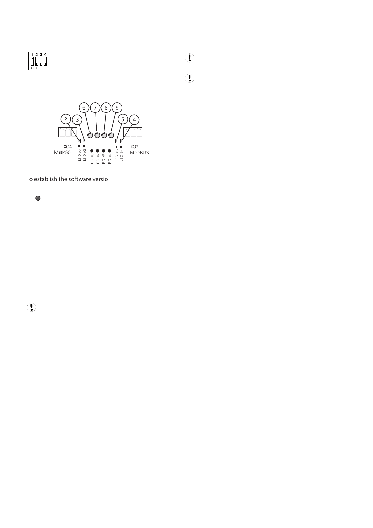
GATEWAY SOFTWARE VERSION DISPLAY
SW3-1
When DIP Switch 1 on SW3 is set to the ‘on’ possition the
LED indicators (LED 2 to 9) will show the software version:
L
E
D
#
6
L
E
D
#
7
L
E
D
#
8
L
E
D
#
9
Multi485
X04
L
E
D
#
2
L
E
D
#
3
L
E
D
#
5
L
E
D
#
4
MODBUS
X03
4
5
6 7 8 9
3
2
To establish the software version number (01 to 255) add
together the ‘value’ associated with each illuminated LED.
LED # Value
6 =1
7 =2
8 =4
9 =8
2 =16
3 =32
5 =64
4 =128
Ignore LED 1 (power on indicator), located adjacent
to X01; this LED will always be on when power is applied.
For example:
1) LED 6 and 8 = ON; all others off
LED 6 = 1
LED 8 = 4
total = 5
Software Version = ‘E05’
2) LED 7 and 8 = ON; all others off
LED 7 = 2
LED 8 = 4
total = 6
Software Version = ‘E06’
3) LED 6, 7, 9 and 2 = ON; all others off
LED 6 = 1
LED 7 = 2
LED 9 = 8
LED 2 = 16
total = 27
Software Version = ‘E27’
The LED indicators will continue to display the the
software version, regardless of operation, until switch 1
on SW3 is set to the ‘off’ possition.
DIP Switch 1 on SW3 must always be set to the ‘off’
position for normal operation.
DIP Switch 1 on SW3 has no function with earlier
software versions; if the LED indicators continue to
operate normally when SW3-1 is switched on, the
software is an earlier version; update the software.
Please refer to the table on the following page to assist in
decoding the software version number.
16
Page 17

oding The Software Version Number
Dec
LED#2
LED#3
LED#6
LED#7
LED#8
LED#9
LED#5
0 0 0 0 0 0 0 0 0
0 0 1 0 0 0 0 0 1
0 0 0 1 0 0 0 0 2
0 0 1 1 0 0 0 0 3
0 0 0 0 1 0 0 0 4
0 0 1 0 1 0 0 0 5
0 0 0 1 1 0 0 0 6
0 0 1 1 1 0 0 0 7
0 0 0 0 0 1 0 0 8
0 0 1 0 0 1 0 0 9
0 0 0 1 0 1 0 0 10
0 0 1 1 0 1 0 0 11
0 0 0 0 1 1 0 0 12
0 0 1 0 1 1 0 0 13
0 0 0 1 1 1 0 0 14
0 0 1 1 1 1 0 0 15
1 0 0 0 0 0 0 0 16
1 0 1 0 0 0 0 0 17
1 0 0 1 0 0 0 0 18
1 0 1 1 0 0 0 0 19
1 0 0 0 1 0 0 0 20
1 0 1 0 1 0 0 0 21
1 0 0 1 1 0 0 0 22
1 0 1 1 1 0 0 0 23
1 0 0 0 0 1 0 0 24
1 0 1 0 0 1 0 0 25
1 0 0 1 0 1 0 0 26
1 0 1 1 0 1 0 0 27
1 0 0 0 1 1 0 0 28
1 0 1 0 1 1 0 0 29
1 0 0 1 1 1 0 0 30
1 0 1 1 1 1 0 0 31
0 0 0 0 0 0 0 0 32
0 0 1 0 0 0 0 0 33
0 0 0 1 0 0 0 0 34
0 0 1 1 0 0 0 0 35
0 0 0 0 1 0 0 0 36
0 0 1 0 1 0 0 0 37
0 0 0 1 1 0 0 0 38
0 0 1 1 1 0 0 0 39
0 0 0 0 0 1 0 0 40
0 0 1 0 0 1 0 0 41
0 0 0 1 0 1 0 0 42
0 0 1 1 0 1 0 0 43
0 0 0 0 1 1 0 0 44
0 0 1 0 1 1 0 0 45
0 0 0 1 1 1 0 0 46
0 0 1 1 1 1 0 0 47
1 1 0 0 0 0 0 0 48
1 1 1 0 0 0 0 0 49
LED#4
COMMISSIONING PROCEDURE
1) B
efore applying power to the X-IRI Gateway ensure:
a)
Version
The MODBUS address is set to the correct value
(switches 1-4 on SW1 and switches 1- 3 on SW2)
b)
The MODBUS port setup matches the MODBUS
master’s requirements. Switches 4 on SW2 and
switches 2-4 on SW3.
c)
The communication link wires from the Gateway
to the compressor controller and the MODBUS
master are connected, secure and the wire
polarities are correct (L1, L2).
2) Apply power to the X-IRI Gateway
3) Ensure communications with the compressor controller
is established – ensure indicator (9) is ON permanently.
4) Once the IR-BUS compressor controller communication
link is established the MODBUS master unit can start
operating. Any attempt from the MODBUS master to
communicate before the IR-BUS link is established will
simply result in the gateway not responding to the
MODBUS master.
5) Once the MODBUS master communicates with the
compressor controller through the gateway it should
keep on doing so at least once every 10 seconds to keep
indicator (6) from flashing.
6) In case the MODBUS master does not communicate at
least once every 10 seconds the communication link is
considered inactive: indicator (6) flashes and any earlier
commands for the compressor controller to operate in
“Host” mode are cancelled => the machine reverts back
to local start/stop and load/unload control mode.
17
Page 18
SECTION 6 PARTS LIST
1
L
E
D
#
6
L
E
D
#
7
L
E
D
#
8
L
E
D
#
9
s
c
r
e
e
n
L
2
L
1
12 13 23
Multi485
X05
s
c
r
e
e
n
L
2
L
1
12 13 23
MODBUS
X03
1 2
+
2
4
V
a
c
/
d
c
0
V
a
c
/
d
c
X01
X02
X04
L
E
D
#
1
2
3
4
1
ON
OFF
6
7
8
5
1
0
1
1
1
2
9
SW1 SW2 SW 3
L
E
D
#
2
L
E
D
#
3
L
E
D
#
5
L
E
D
#
4
2
3
DC
+V.ADJ
L
N
24V DC
100-240VAC
50/60Hz
E
N
L
0VDC
+24VDC
1
6
2
3
5
4
RJ11
2
4
3
5
M4
Ring Tag
L1 (2)
L2 (4)
2
4
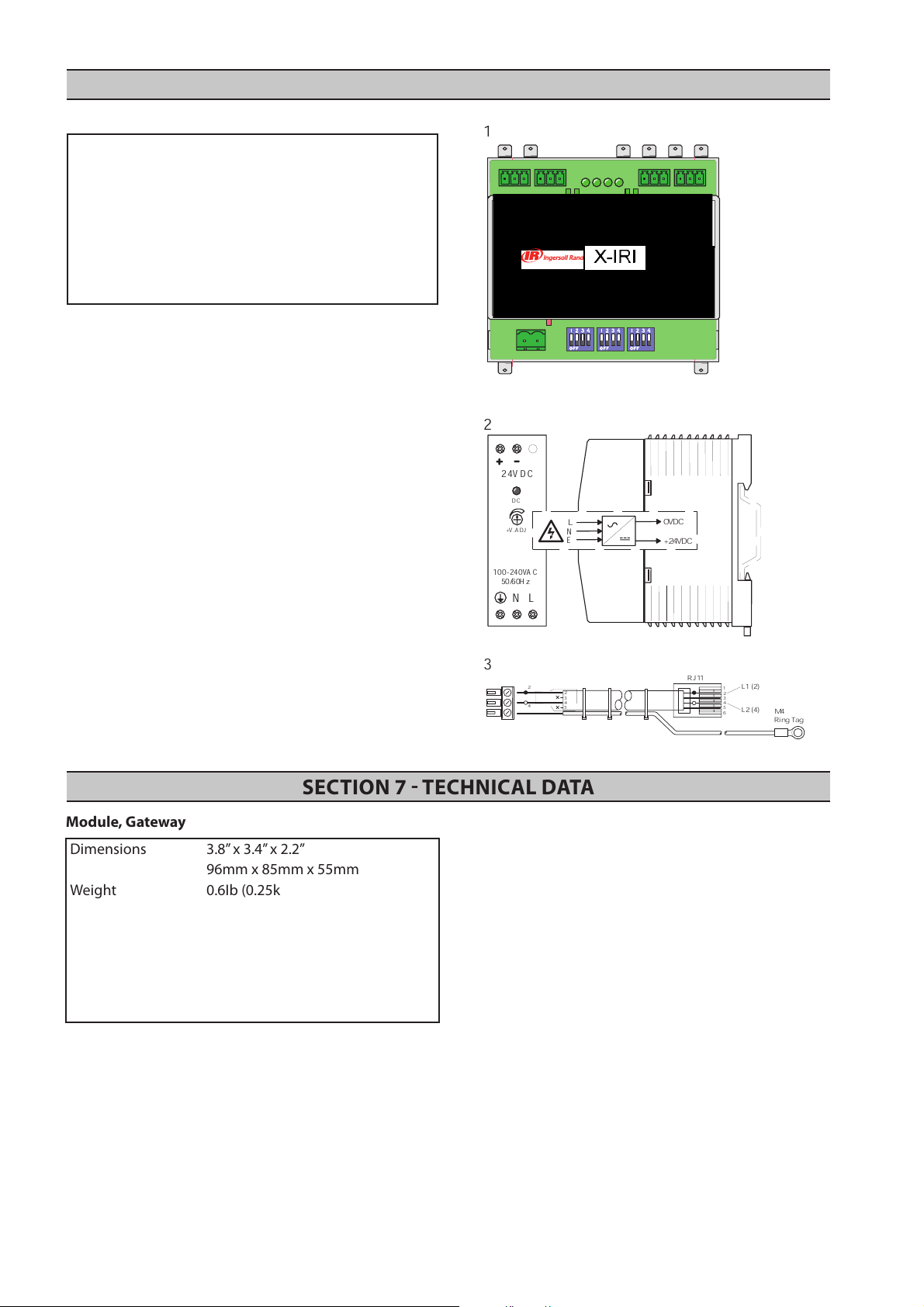
SECTION 7 TECHNICAL DATA
Module, Gateway
Dimensions 3.8” x 3.4” x 2.2”
96mm x 85mm x 55mm
Weight 0.6Ib (0.25kg)
Mounting DIN, 35mm
Enclosure IP20
Supply 24VDC/ac +/-15%
Power 1.0VA
Temperature 0°C to 46°C (32°F to 115°F)
Humidity 95% RH non-condensing
X
-IRI Communication Gateway
Item Part No. Description
-
- 80445604 Manual, User CD
- 23462005 DIN Rail, Mounting
1 23461890 Module, X-IRI Gateway
2 39266101 Module, PSU-24VDC
3 39266135
23461908 KIT, X-IRI Gateway
Cable, RJ11 Modbus
18
Page 19
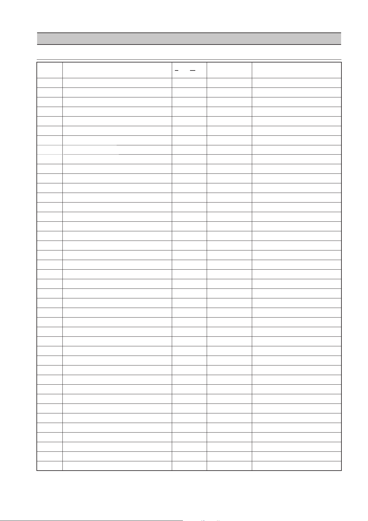
SECTION 8 INTELLISYS MODBUS TABLES
TABLE 1 SSR REDEYE CONTROLLER
Register
(40X
64 Total Hours (hours) R
65 Loaded Hours (hours) R
96 Language Selection R See FIGURE 1-2
97 Units of Measure R See FIGURE 1-2
98 Rated Pressure R
99 Rated Horse Power R See FIGURE 1-2
112 Offline Pressure R/W 75 - (rated+3) rated = rated pressure
113 Online Pressure R/W 65-(offline-10) offline = offline pressure
114 Display Timer (seconds) R/W 10-600
115 Star-Delta Time (seconds) R
116 Auto Start/Stop (AS/S) Time (minutes) R/W Feb-60 No Write if AS/S is off
117 Auto Start/Stop (AS/S) On/Off R 0 or 1 0=Off, 1=On
118 Sequence Control On/Off R 0 or 1 0=Off, 1=On
119 Remote Start/Stop On/Off R 0 or 1 0=Off, 1=On
120 Mod Only On/Off R/W 0 or 1 0=Off, 1=On
121 Power Out Restart Option (PORO)On/Off R 0 or 1 0=Off, 1=On
122 PORO Time (seconds) R/W 10-120 No Write if PORO is off
123 Load Delay Time (seconds) R/W 0-60
124 Min. Cooler Out Load Temp R/W 30-150 Low Ambient Option
125 Unloaded Stop Time R/W 10-30
255 Warning Code R See FIGURE 1-4
256-270 Alarm Code History R See FIGURE 1-4
272-286 Inlet Vacuum Alarm History R
288-302 Sump Pressure Alarm History R
304-318 Discharge Pressure Alarm History R
320-334 Coolant Temperature Alarm History R
336-350 Airend Temperature Alarm History R
352-366 Discharge Temperature Alarm History R
368-382 Low Ambient Coolant Temp. History R Low Ambient Option
384-398 Run Hours Alarm History R
400-414 Load Hours Alarm History R
512-526 Status Alarm History R See FIGURE 1-3
999 IRI Version Number R Reads from IRI only
Variable
XX)
1 Status/Control R/W See FIGURE 1-1
3 Discharge Pressure R
4 Sump Pressure R
5 Inlet Vacuum R
6 Coolant Temperature R
7 Airend Temperature R
8 Discharge Temperature R
9 Low Ambient Coolant Temp. R Low Ambient Option
Read/Write Range Not
es
19
Page 20

FIGURE 11 REGISTER 40001 STATUS / CONTROL
Bit 0: Host/Local (R/W) Bit 6: A
larm (R)
0 = Local 0 = No Alarms
1 = Host 1 = Alarms
Bit 1: Run/Stop (R/W) Bit 7: Warning (R)
0 = Stop 0 = No Warnings
1 = Run 1 = Warnings
Bit 2: Load/Unload (R/W) Bit 8: On/Off Line Mode (R)
0 = Unload 0 = Not in On/Off Line Mode
1 = Load 1 = On/Off Line Mode
Bit 3: Modulating (R) Bit 9: Mod/ACS or Mod Only (R)
0 = Not Modulating 0 = Not in Mod/ASC Mode
1 = Modulating 1 = Mod/ASC Mode
Bit 4: Unused Bits 10-12: Unused
Bit 5: Stopped in Auto Restart (R) Bits 13-15: Unit Type (R)
0 = Not Stopped in Auto Restart 001 = SSR controller
FIGURE 12 REGISTER CODES
Register 096: Language Regist
er 097: Units of Measure
0 = English 0 = °F and PSI
1 = Spanish 1 = °C and PSI
2 = French 2 = °C and Bar
3 = Portuguese 3 = °C and kPa
4 = °C and kg/cm
2
Register 99: Rated Horse Power/Kilowatt
0 = 50hp 7 = 250hp
1 = 60hp 8 = 300hp
2 = 75hp 9 = 350hp
3 = 100hp 10 = 400hp
4 = 125hp 11 = 450hp
5 = 150hp 12 = 500hp
6 = 200hp
FIGURE 13 REGISTER STATUS ALARM HISTORY
Bit 0: Run/Stop (R) Bit 4: S
topped Auto Restart (R)
0 = Stop 0 = Not Stopped in Auto Restart
1 = Run 1= Stopped in Auto Restart
Bit 1: On/Off Line Mode (R) Bit 5: Unused
0 = Not in On/Off Line Mode
1 = On/Off Line Mode
Bit 2: MOD/ACS Mode (R) Bit 6: Unused
0 = Not in Mod/ACS Mode
1 = Mod/ACS Mode
Bit 3: Load/Unload (R) Bit 7: Unused
20
Page 21

IGURE 14 REGISTER ALARM / WARNING CODES
F
SSR (Redeye) Controller
C
ode Description
01 Sensor Failure 1AVPT
02 Sensor Failure 3APT
03 Sensor Failure 4APT
04 Sensor Failure P4 (Spare)
05 Sensor Failure P5 (Spare)
06 Sensor Failure P6 (Spare)
07 Sensor Failure P7 (Spare)
08 Sensor Failure P8 (Spare)
09 Sensor Failure 2CTT
10 Sensor Failure 2ATT
11 Sensor Failure 4ATT
12 Sensor Failure 3CTT (Optional)
13 Sensor Failure T5 (Spare)
14 Sensor Failure T6 (Spare)
15 Sensor Failure T7 (Spare)
16 Sensor Failure T8 (Spare)
17 Starter Fault
18 Motor Overload (Main)
19 Fan Motor Overload
20 Door Open (Starter)
21 Stepper Limit Switch
22 Check Motor Rotation
23 Check Inlet Control System
25 Remote Stop Failure
26 Remote Start Failure
27 Check Inlet Control
28 Low Unload Sump Pressure
29 High Air Pressure
30 Low Sump Air Pressure
31 High A/E Discharge Temperature
32 Emergency Stop
33 Change Inlet Filter
34 Change Separator Element
35 Change Coolant Filter
36 1AVPT Sensor Error (Calibration)
37 Memory Fault
21
Page 22

TABLE 2 SSR SG CONTROLLER
Register
(40X
10 Separator Pressure Drop R
11 Spare Pressure Input 4 R
12 Dry Side Sump Pressure R Spare Pressure Input #5 if no
13 Spare Pressure Input 6 R
14 Spare Pressure Input 7 R
15 Remote Pressure R Spare Pressure Input #8 if no
16 Spare Temperature Input 5 R
17 Spare Temperature Input 6 R
18 Spare Temperature Input 7 R
19 Spare Temperature Input 8 R
20 % Load Modulation R
64 Total Hours (hours) R 0 – 9999 Less Than 10000
65 Loaded Hours (hours) R 0 – 9999 Less Than 10000
66 Ten Thousand Total Hours R Multiply by 10000
67 Ten Thousand Loaded Hours R Multiply by 10000
96 Language Selection R 0 – 11 See FIGURE 2-2
97 Units of Measure R 0 – 4 See FIGURE 2-2
98 Rated Pressure R
99 Rated Horse Power /Kilowatt R 0 – 21 See FIGURE 2-2
100 Starter Type R 0 - 4 See FIGURE 2-2
101 Service Level R 0 or 1 0=Level 1, 1=Level 2
102 Service Type R 0 or 1 0=Hours, 1=Months
103 Service Interval R 0 - 3 3, 6, 9, or 12 months
112 Offline Pressure R/W 75 - (rated+3) rated = rated pressure
113 Online Pressure R/W 65-(offline-10) offline = offline pressure
114 Mode of Operation R/W 0 – 2 See FIGURE 2-2
115 Star-Delta Time (seconds) R 5 – 20
116 Auto Start/Stop (AS/S) Time (minutes) R/W 2 – 60 No Write if AS/S is off
117 Auto Start/Stop (AS/S) On/Off R 0 or 1 0=Off, 1=On
118 Sequence Control On/Off R 0 or 1 0=Off, 1=On
119 Remote Start/Stop On/Off R 0 or 1 0=Off, 1=On
120 Solenoid Delta-P R 0 or 1 0=Off, 1=On
121 Power Out Restart Option (PORO)On/Off R 0 or 1 0=Off, 1=On
122 PORO Time (seconds) R/W 10-120 No Write if PORO is off
Variable
XX)
1 Status/Control R/W See FIGURE 2-1
3 Discharge Pressure R
4 Sump Pressure R
5 Inlet Vacuum R Divided by 10
6 Coolant Temperature R
7 Airend Temperature R
8 Discharge Temperature R
9 Low Ambient Coolant Temp. R Low Ambient Option
Read/Write Range Not
separator delta-p sensor option
remote sensor option
es
22
Page 23

123 Auto Start/Stop Delay Time (seconds) R/W 0-60
124
125 Unloaded Stop Time R/W 10-30t
126 Low Ambient Option On/Off R 0 or 1 0=Off, 1=On
127 Contrast R 0 - 10
128 Lead/Lag R/W 0 or 1 0=Off, 1=On
129 Lag Offset R/W 0 - 10
130 Max Modulation Pressure R/W (Online+10) –
131 Lead/Lag Cycle Length (Hours) R/W 0 – 750
132 Scheduled Start (Hour) R/W 0 – 23
133 Scheduled Start (Minute) R/W 0 – 59
134 Scheduled Stop (Hour) R/W 0 – 23
135 Scheduled Stop (Minute) R/W 0 – 59
136 Modbus Protocol R 0 or 1 0=Off, 1=On
137 Modbus Address R 1 – 247
138 High Dust Filter R 0 or 1 0=Off, 1=On
139 Integral Sequencing Lead R/W 0 – 3 0=Off, 1=On, 2=Always, 3=Never
140 Integral Sequencing Address R/W 1 – 4
141 Integral Sequencing Total R/W 2 – 4
142 Integral Sequencing Load Delay R/W 10 – 60
143 Integral Sequencing Lead Change (Hours) R/W 0 – 750
144 Integral Sequencing Lead Change – Day R/W 0 – 9 See FIGURE 2-2
145 Integral Sequencing Lead Change – Hour R/W 0 – 23
146 Integral Sequencing Lead Change – Min R/W 0 – 45 Steps of 0, 15, 30, 45
147 Separator Delta-P Sensor R 0 or 1 0=Off, 1=On
148 Variable Frequency Drive R 0 or 1 0=Off, 1=On
149 Scheduled Start (Day) R/W 0 - 9 See FIGURE 2-2
150 Scheduled Stop (Day) R/W 0 - 9 See FIGURE 2-2
151 Remote Sensor R 0 or 1 0=Off, 1=On
250 Options R See FIGURE 2-2
251 Unloaded Inlet Vacuum R
252 Software Part Number – Most Significant R High Digits
253 Software Part Number – Least Significant R Low Digits
254 Software Version Number R
255 Warning Code R See FIGURE 2-4
256-270 Alarm Code History R See FIGURE 2-4
272-286 Inlet Vacuum Alarm History R
288-302 Sump Pressure Alarm History R
304-318 Discharge Pressure Alarm History R
320-334 Coolant Temperature Alarm History R
336-350 Airend Temperature Alarm History R
352-366 Discharge Temperature Alarm History R
368-382 Low Ambient Coolant Temp. History R Low Ambient Option
384-398 Total Hours Alarm History R Less Than 10000 Hours
400-414 10000 Total Hours Alarm History R Multiply by 10000
416-430 Loaded Hours Alarm History R Less Than 10000 Hours
432-446 10000 Loaded Hours Alarm History R Multiply by 10000
448-462 Unloaded Inlet Vacuum Alarm History R
464-478 Coolant Pressure Alarm History R
480-494 Dry Side Sump Pressure Alarm History R
496-510 Remote Pressure Alarm History R
512-526 Status Alarm History R See FIGURE 2-3
528-542 Real Time Clock Alarm History – Hours R
544-558 Real Time Clock Alarm History – Minutes R
560-574 Real Time Clock Alarm History – Month R
576-590 Real Time Clock Alarm History – Date R
592-606 Real Time Clock Alarm History – Year R
999 IRI Version Number R Reads from IRI only
Min. Cooler Out Load Temp R/W 30-150 Low Ambient Option
(Offline + 7)
23
Page 24

FIGURE 21 REGISTER 40001 STATUS / CONTROL
Bit 0: Host/Local (R/W) Bit 6: A
larm (R)
0 = Local 0 = No Alarms
1 = Host 1 = Alarms
Bit 1: Run/Stop (R/W) Bit 7: Warning (R)
0 = Stop 0 = No Warnings
1 = Run 1 = Warnings
Bit 2: Load/Unload (R/W) Bit 8: On/Off Line Mode (R)
0 = Unload 0 = Not in On/Off Line Mode
1 = Load 1 = On/Off Line Mode
Bit 3: Modulating (R) Bit 9: Mod/ACS or Mod Only (R)
0 = Not Modulating 0 = Not in Mod/ASC Mode
1 = Modulating 1 = Mod/ASC Mode
Bit 4: Unused Bits 10-12: Unused
Bit 5: Stopped in Auto Restart (R) Bits 13-15: Unit Type (R)
0 = Not Stopped in Auto Restart 001 = SSR controller
1 = Stopped in Auto Restart
FIGURE 22 REGISTER CODES
Register 096: Language
Register 097: Units of Measure
0 = English 0 = °F and PSI
1 = Spanish 1 = °C and PSI
2 = Portuguese 2 = °C and Bar
3 = French 3 = °C and kPa
4 = Italian 4 = °C and kg/cm
5 = Dutch
6 = German
7 = Danish
8 = Norwegian
9 = Swedish
10 = Finnish
11 = Turkish
2
Register 99: Rated Horse Power/Kilowatt Register 100: Starter Type
0 = 50hp 11 = 450hp 0 = Star-Delta
1 = 60hp 12 = 500hp 1 = Full Voltage
2 = 75hp 13 = 75kw 2 = Remote Star-Delta
3 = 100hp 14 = 90kw 3 = Remote Full Voltage
4 = 125hp 15 = 110kw 4 = Soft Starter
5 = 150hp 16 = 132kw
6 = 200hp 17 = 150kw
7 = 250hp 18 = 200kw
8 = 300hp 19 = 250kw
9 = 350hp 20 =300kw
10 = 400hp 21 = 250kw
Register 114: Mode of Operation Register 144: Integral Sequencing Lead Change - Day
0 = MOD/ACS Register 149: Schedule Start - Day
1 = On/Off Line Register 150: Schedule Stop - Day
2 = Modulation Only 0= Sunday
1 = Monday
2 = Tuesday
3 = Wednesday
4 = Thursday
5 = Friday
6 = Saturday
7 = Daily
8 = Weekdays
9 = Weekends
Register 250: Options
Bit 0: Power Out Restart and Scheduled Start/Stop
0 = Off
1 = On
24
Page 25

IGURE 23 REGISTER STATUS ALARM HISTORY
F
Bit 0: Run/Stop (R) Bit 4: S
0 = Stop 0 = Not Stopped in Auto Restart
1 = Run 1 = Stopped in Auto Restart
Bit 1: On/Off Line Mode (R) Bit 5: Unused
0 = Not in On/Off Line Mode
1 = On/Off Line Mode
Bit 2: MOD/ACS Mode (R) Bit 6: Unused
0 = Not Modulating
1 = Modulating
Bit 3: Load/Unload (R) Bit 7: Unused
0 = Unload
1 = Load
topped Auto Restart (R)
25
Page 26

IGURE 24 REGISTER ALARM / WARNING CODES
F
SSR (SG) Controller
C
ode Description
01 Sensor Failure 1AVPT
02 Sensor Failure 3APT
03 Sensor Failure 4APT
04 Sensor Failure 5CPT (Optional)
05 Sensor Failure 6APT (Optional)
06 Sensor Failure P6 (Spare)
07 Sensor Failure P7 (Spare)
08 Sensor Failure P8 (Spare)
09 Sensor Failure 2CTT
10 Sensor Failure 2ATT
11 Sensor Failure 4ATT
12 Sensor Failure 3CTT (Optional)
13 Sensor Failure T5 (Spare)
14 Sensor Failure T6 (Spare)
15 Sensor Failure T7 (Spare)
16 Sensor Failure T8 (Spare)
17 Starter Fault
18 Motor Overload (Main)
19 Fan Motor Overload
20 Control Power Loss
21 Stepper Limit Switch
22 Check Motor Rotation
23 Check Inlet Control System
25 Remote Stop Failure
26 Remote Start Failure
27 Check Inlet Control
28 Low Unload Sump Pressure
29 High Air Pressure
30 Low Sump Air Pressure
31 High A/E Discharge Temperature
32 Emergency Stop
33 Change Inlet Filter
34 Change Separator Element
35 Change Coolant Filter
36 1AVPT Sensor Error (Calibration)
37 Memory Fault
38 100 Hours/14 Days To Service
39 Service Required
40 Alarm - Service Required
41 Auxiliary 2
42 Auxiliary 1
43 High Line/Sump Differential
44 Communication Failure 1
45 Communication Failure 2
46 Communication Failure 3
47 Communication Failure 4
48 Low Coolant Pressure
26
Page 27

TABLE 3 SSR SE 15100HP CONTROLLER
Register
(40X
64 Total Hours (hours) R
65 Loaded Hours (hours) R
96 Language Selection R See FIGURE 3-2
97 Units of Measure R See FIGURE 3-2
98 Rated Pressure R
99 Starter Type R See FIGURE 3-2
100 Star-Delta Timer (seconds) R
101 Contrast R
102 Modulation On/Off (v1.5 or higher) R 0 or 1 0=Off, 1=On
112 Offline Pressure R/W 75 - (rated+3)
113 Online Pressure R/W 65-(offline-10)
114 Mode of Operation R/W 0-2 See FIGURE 3-2
115 Display Timer (seconds) R/W 10-600
116 Auto Start/Stop (AS/S) On/Off R 0 or 1 0=Off, 1=On
117 Auto Start/Stop Time (minutes) R/W 2-20 No Write if AS/S is off
118 Sequence Control On/Off R 0 or 1 0=Off, 1=On
119 Remote Start/Stop On/Off R 0 or 1 0=Off, 1=On
120 Power Out Restart Option(PORO) On/Off R 0 or 1 0=Off, 1=On
121 PORO Time (seconds) R/W 10-120 No Write if PORO is off
122 Load Delay Time (seconds) R/W 0-60
123 Lead/Lag (v1.5 or higher) R/W 0 or 1 0=Lead, 1=Lag
124 Lag Offset (v1.5 or higher) R/W 0-45 psi
125 Low Ambient Option (v1.6 or higher) R 0 or 1 0=Off, 1=On
252 Part Number (v1.5 or higher) R High 16-bits
253 Part Number (v1.5 or higher) R Lower 16-bits
254 Software Version (v1.5 or higher) R
255 Warning Code R See FIGURE 3-4
256-270 Alarm Code History R See FIGURE 3-4
272-286 Discharge Pressure Alarm History R
288-302 Sump Pressure Alarm History R
304-318 Airend Temperature Alarm History R
320-334 Separator Pressure Alarm History R
336-350 Run Hours Alarm History R
352-366 Load Hours Alarm History R
368-382 Status Alarm History R See FIGURE 3-3
999 IRI Version Number R Reads from IRI only
Variable
XX)
1 Status/Control R/W See FIGURE 3-1
3 Discharge Pressure R
4 Sump Pressure R
5 Separator Pressure Drop R
6 Airend Temperature R
Read/Write Range Not
es
27
Page 28

IGURE 31 REGISTER 40001 STATUS / CONTROL
F
Bit 0: Host/Local (R/W) Bit 6: A
larm (R)
0 = Local 0 = No Alarms
1 = Host 1 = Alarms
Bit 1: Run/Stop (R/W) Bit 7: Warning (R)
0 = Stop 0 = No Warnings
1 = Run 1 = Warnings
Bit 2: Load/Unload (R/W) Bit 8: On/Off Line Mode (R)
0 = Unload 0 = Not in On/Off Line Mode
1 = Load 1 = On/Off Line Mode
Bit 3: Modulating (R) Bit 9: Mod/ACS or Mod Only (R)
0 = Not Modulating 0 = Not in Mod/ASC Mode
1 = Modulating 1 = Mod/ASC Mode
Bit 4: Sump Pressure (R/W) Bits 10-12: Unused
1 = Get Sump Pressure
Bit 5: Stopped in Auto Restart (R) Bits 13-15: Unit Type (R)
0 = Not Stopped in Auto Restart 010 = SE controller
1 = Stopped in Auto Restart
FIGURE 32 REGISTER CODES
Register 096: Language
Register 097: Units of Measure
0 = English 0 = °C and Bar
1 = Spanish 1 = °C and PSI
2 = French 2 = °C and kPa
3 = Portuguese 3 = °F and PSI
4 = °C and kg/cm
2
Register 99: Starter Type Register 114: Mode of Operation
0 = Full Voltage 0 = MOD/ACS
1 = Star-Delta 1 = Modulation Only
2 = No Starter 2 = On/Off Line
FIGURE 33 REGISTER STATUS ALARM HISTORY
Bit 0: Run/Stop (R) Bit 4: S
topped Auto Restart (R)
0 = Stop 0 = Not Stopped in Auto Restart
1 = Run 1= Stopped in Auto Restart
Bit 1: On/Off Line Mode (R) Bit 5: Unused
0 = Not in On/Off Line Mode
1 = On/Off Line Mode
Bit 2: MOD/ACS Mode (R) Bit 6: Unused
0 = Not Modulating
1 = Modulating
Bit 3: Load/Unload (R) Bit 7: Unused
0 = Unload
1 = Load
28
Page 29

IGURE 34 REGISTER ALARM / WARNING CODES
F
SSR (SE) 15-100HP CONTROLLER
C
ode Description
01 Pressure Sensor Failure
02 Temperature Sensor Failure 1
04 Starter Fault
05 Motor Overload
06 Reverse Rotation
07 Remote Stop Failure
08 Remote Start Failure
09 Calibration Error
10 High Airend Discharge Temperature
12 High Pressure
15 Separator Element
16 Control Power Loss
17 Fan Motor Overload
18 Emergency Stop
19 Low Sump Pressure
20 Memory Fault
21 Low Unloaded Sump Pressure
29
Page 30

TABLE 4 SIERRA REDEYE 125200 HP CONTROLLER
Register
(40X
112 Offline Pressure R/W 75 - (rated+3) rated = rated pressure
113 Online Pressure R/W 65-(offline-10) offline = offline pressure
114 Display Timer (seconds) R/W 10-600
115 Condensate Time (seconds) R/W 90-270
116 Start-Delta Time (seconds) R 10-20
117 Auto Start/Stop Time (seconds) R/W 2-60 No Write if AS/S is off
118 Max. 1st Stage Temperature R/W 310-410
119 Max. 2nd Stage Temperature R/W Variable Refer to Sierra’s Manual
120 PORO Time (seconds) R/W 10-120 No Write if PORO is off
121 Auto Start/Stop On/Off R 0 or 1 0=Off, 1=On
122 PORO On/Off R 0 or 1 0=Off, 1=On
123 Remote Start/Stop On/Off R 0 or 1 0=Off, 1=On
124 Sequence Control On/Off R 0 or 1 0=Off, 1=On
125 Condensate Level On/Off R 0 or 1 0=Off, 1=On
126 Water Unit Yes/No R 0 or 1 0=No, 1=Yes
255 Warning Code R See FIGURE 4-4
256-270 Alarm Code History R See FIGURE 4-4
272-286 Inlet Vacuum Alarm History R
288-302 2nd Stage Inlet Pressure Alarm History R
304-318 2nd Stage Discharge Press. Alarm History R
320-334 Package Discharge Press. Alarm History R
336-350 Oil Filter In Pressure Alarm History R
352-366 Bearing Oil Pressure Alarm History R
368-382 1st Stage Discharge Temp Alarm History R
384-398 2nd Stage Inlet Temp Alarm History R
400-414 2nd Stage Discharge Temp Alarm History R
512-526 Bearing Oil Temp Alarm History R
528-542 Package Discharge Air Temp Alarm History R
544-558 Run Hours Alarm History R
560-574 Run Hours, Ten Thousand, Alarm History R
576-590 Load Hours Alarm History R
592-606 Load Hours, Ten Thousand, Alarm History R
608-622 Status Alarm History R See FIGURE 4-3
999 IRI Version Number R Reads from IRI only
Variable
XX)
1 Status/Control R/W See FIGURE 4-1
3 Discharge Pressure R
4 2nd Stage Inlet Pressure R
5 2nd Stage Discharge Pressure R
6 Inlet Vacuum R
7 Oil Filter In Pressure R
8 Bearing Oil Pressure R
9 1st Stage Discharge Temp. R
10 2nd Stage Inlet Temp. R
11 2nd Stage Discharge Temp. R
12 Bearing Oil Temp. R
13 Package Discharge Temp. R
64 Running Hours (<10,000 hours) R
65 Ten Thousand Running Hours R Multiply value by 10,000
66 Load Hours (<10,000 hours) R
67 Ten Thousand Load Hours R Multiply value by 10,000
96 Language Selection R See FIGURE 4-2
97 Units of Measure R See FIGURE 4-2
98 Rated Pressure R
Read/Write Range Not
es
30
Page 31

IGURE 41 REGISTER 40001 STATUS / CONTROL
F
Bit 0: Host/Local (R/W) Bit 6: A
larm (R)
0 = Local 0 = No Alarms
1 = Host 1 = Alarms
Bit 1: Run/Stop (R/W) Bit 7: Warning (R)
0 = Stop 0 = No Warnings
1 = Run 1 = Warnings
Bit 2: Load/Unload (R/W) Bit 8: On/Off Line Mode (R)
0 = Unload 0 = Not in On/Off Line Mode
1 = Load 1 = On/Off Line Mode
Bit 3: Unused Bit 9: Unused
Bit 4: Unused Bits 10-12: Unused
Bit 6: Stopped in Auto Restart (R) Bits 13-15: Unit Type (R)
0 = Not Stopped in Auto Restart 100 = Sierra controller
1 = Stopped in Auto Restart
FIGURE 42 REGISTER CODES
Register 096: Language Regist
er 097: Units of Measure
0 = English 0 = °F and PSI
1 = Spanish 1 = °C and PSI
2 = Portuguese 2 = °C and Bar
3 = °C and kPa
4 = °C and kg/cm
2
FIGURE 43 REGISTER STATUS ALARM HISTORY
Bit 0: Run/Stop (R) Bit 4: S
topped Auto Restart (R)
0 = Stop 0 = Not Stopped in Auto Restart
1 = Run 1 = Stopped in Auto Restart
Bit 1: On/Off Line Mode (R) Bit 5: Unused
0 = Not in On/Off Line Mode Bit 6: Unused
1 = On/Off Line Mode Bit 7: Unused
Bit 2: Unused
Bit 3: Load/Unload (R)
0 = Unload
1 = Load
31
Page 32

IGURE 44 REGISTER ALARM / WARNING CODES
F
SIERRA (REDEYE) 125-200 HP CONTROLLER
C
ode Description
01 Sensor Failure 1AVPT
02 Sensor Failure 2APT
03 Sensor Failure 3APT
04 Sensor Failure 4APT
05 Sensor Failure 5OPT
06 Sensor Failure 6OPT
07 Sensor Failure P7 (Spare)
08 Sensor Failure P8 (Spare)
09 Sensor Failure 2ATT
10 Sensor Failure 3ATT
11 Sensor Failure 4ATT
12 Sensor Failure 5OTT
13 Sensor Failure 7ATT
14 Sensor Failure T6 (Spare)
15 Sensor Failure T7 (Spare)
16 Sensor Failure T8 (Spare)
17 Starter Fault
18 Motor Overload (Main)
19 Fan Motor Overload
20 High 1st Stage Discharge Temp.
21 High 2nd Stage Discharge Temp.
22 High Bearing Oil Temp.
23 High I/C Air Temp,
24 Unused
25 Remote Stop Failure
26 Remote Start Failure
27 High Vacuum
28 High Loaded Vacuum
29 High Discharge Air Pressure
30 Low Bearing Oil Pressure
31 High I/C Pressure (Loaded)
32 Emergency Stop
33 Change Inlet Filter
34 High I/C Pressure (Unloaded)
35 Change Coolant Filter
36 High 2nd Stage Pressure
37 Memory Fault
38 Low Water Flow
39 High Condensate
32
Page 33

TABLE 5 SIERRA SE 50100 HP CONTROLLER
Register
(40X
100 Star-Delta Timer (seconds) R
101 Contrast R
112 Offline Pressure R/W 75 - (rated+3)
113 Online Pressure R/W 65-(offline-10)
114 Display Timer (seconds) R/W 10-600
115 Auto Start/Stop On/Off R 0 or 1 0=Off, 1=On
116 Auto Start/Stop Time (minutes) R/W 2-60 No Write if AS/S is off
117 Condensate Switch On/Off R 0 or 1 0=Off, 1=On
118 Sequence Control On/Off R 0 or 1 0=Off, 1=On
119 Remote Start/Stop On/Off R 0 or 1 0=Off, 1=On
120 PORO On/Off R 0 or 1 0=Off, 1=On
121 PORO Time (seconds) R/W 10-120 No Write if PORO is off
122 Load Delay Time (seconds) R/W 0-60
123 Lead/Lag R/W 0 or 1 0=Lead, 1=Lag
124 Lag Offset R/W 0-45 psi
125 Condensate Discharge Time (seconds) R/W 2-10
126 Condensate Interval Time (seconds) R/W 90-270
252 Part Number R High 16-bits
253 Part Number R Lower 16-bits
254 Software Version R
255 Warning Code R See FIGURE 5-4
256-270 Alarm Code History R See FIGURE 5-4
272-286 Discharge Pressure Alarm History R
288-302 Package Disch. Temp. Alarm History R
304-318 Bearing Oil Temp. Alarm History R
320-334 2nd Stage Inlet Temp. Alarm History R
336-350 2nd Stage Disch. Temp. Alarm History R
352-366 1st Stage Disch. Temp. Alarm History R
368-382 Run Hours Alarm History R
384-398 Load Hours Alarm History R
400-414 Status Alarm History R See FIGURE 5-3
999 IRI Version Number R Reads from IRI only
Variable
XX)
1 Status/Control R/W See FIGURE 5-1
3 Discharge Pressure R
4 Package Discharge Temp. R
5 Bearing Oil Temp. R
6 2nd Stage Inlet Temp. R
7 2nd State Discharge Temp. R
8 1st Stage Discharge Temp. R
64 Total Hours (hours) R
65 Loaded Hours (hours) R
96 Language Selection R See FIGURE 5-2
97 Units of Measure R See FIGURE 5-2
98 Rated Pressure R
99 Starter Type R See FIGURE 5-2
Read/Write Range Not
es
33
Page 34

IGURE 51 REGISTER 40001 STATUS / CONTROL
F
Bit 0: Host/Local (R/W) Bit 6: A
larm (R)
0 = Local 0 = No Alarms
1 = Host 1 = Alarms
Bit 1: Run/Stop (R/W) Bit 7: Warning (R)
0 = Stop 0 = No Warnings
1 = Run 1 = Warnings
Bit 2: Load/Unload (R/W) Bit 8: On/Off Line Mode (R)
0 = Unload 0 = Not in On/Off Line Mode
1 = Load 1 = On/Off Line Mode
Bit 3: Unused Bit 9: Unused
Bit 4: Sump Pressure (R/W) Bits 10-12: Unused
1 = Get Sump Pressure Bits 13-15: Unit Type (R)
Bit 5: Stopped in Auto Restart (R) 110 = Sierra SE controller
0 = Not Stopped in Auto Restart
1 = Stopped in Auto Restart
FIGURE 52 REGISTER CODES
Register 096: Language Regist
er 097: Units of Measure
0 = English 0 = °C and Bar
1 = Spanish 1 = °C and PSI
2 = French 2 = °C and kPa
3 = Portuguese 3 = °F and PSI
4 = °C and kg/cm
2
Register 99: Starter Type
0 = Full Voltage
1 = Star-Delta
2 = No Starter
FIGURE 53 REGISTER STATUS ALARM HISTORY
Bit 0: Run/Stop (R) Bit 4: S
topped Auto Restart (R)
0 = Stop 0 = Not Stopped in Auto Restart
1 = Run 1 = Stopped in Auto Restart
Bit 1: On/Off Line Mode (R) Bit 5: Unused
0 = Not in On/Off Line Mode Bit 6: Unused
1 = On/Off Line Mode Bit 7: Unused
Bit 2: Unused
Bit 3: Load/Unload (R)
0 = Unload
1 = Load
34
Page 35

IGURE 54 REGISTER ALARM / WARNING CODES
F
SIERRA (SE) 50-100 HP CONTROLLER
C
ode Description
01 Pressure Sensor Failure
02 Package Disch. Temp. Sensor Failure
03 Bearing Oil Temp. Sensor Failure
04 Starter Fault
05 Motor Overload
06 2nd Stage Inlet Temp. Sensor Failure
07 Remote Stop Failure
08 Remote Start Failure
09 Calibration Error
10 2nd Stage Disch. Temp. Sensor Failure
11 1st Stage Disch. Temp. Sensor Failure
12 High Pressure
13 Oil Pressure Switch
14 Condensate Level
15 High Package Disch. Temp.
16 Control Power Loss
17 High Bearing Oil Temp.
18 Emergency Stop
19 High 2nd Stage Inlet Temp.
20 Memory Fault
21 High 1st Stage Disch. Temp.
22 High 2nd Stage Disch. Temp.
35
Page 36

TABLE 6 SIERRA SG 125400 HP CONTROLLER
Register
(40X
100 Power Type R 0 - 1 0=50 Hz, 1=60 Hz
112 Offline Pressure R/W 75 - (rated+3) rated = rated pressure
113 Online Pressure R/W 65-(offline-10) offline = offline pressure
114 Condensate Release Time (seconds) R/W 2-10
115 Condensate Interval Time (seconds) R/W 90-270
116 Start-Delta Time (seconds) R 10-20
117 Auto Start/Stop Time (seconds) R/W 2-60 No Write if AS/S is off
118 Max. 1st Stage Temperature R/W 310-410
119 Max. 2nd Stage Temperature R/W Variable Refer to Sierra’s Manual
120 PORO Time (seconds) R/W 10-120 No Write if PORO is off
121 Auto Start/Stop On R 1 Always On
122 PORO On/Off R 0 or 1 0=Off, 1=On
123 Remote Start/Stop On/Off R 0 or 1 0=Off, 1=On
124 Sequence Control On/Off R 0 or 1 0=Off, 1=On
125 Condensate Level On/Off R 0 or 1 0=Off, 1=On
126 Load Delay Time (seconds) R/W 0 - 60
127 Lead/Lag R/W 0 or 1 0=Lead, 1=La
128 Lag Offset R/W 0 - 45 psi
129 Contrast R 0 - 10
130 Lead/Lag Cycle Length (Hours) R/W 0 - 750
131 Scheduled Start (Hours) R/W 0 - 23
132 Scheduled Start (Minutes) R/W 0 - 59
133 Scheduled Stop (Hours) R/W 0 - 23
134 Scheduled Stop (Minutes) R/W 0 - 59
135 Real Time Hours R 0 - 23
136 Real Time Minutes R 0 - 59
137 Month of Year R 1-12
138 Day of Month R 1-31
139 Year R 0 - 99
140 Integral Sequencing Lead R/W 0 – 3 0=Off, 1=On, 2=Always, 3=Never
141 Integral Sequencing Total R/W 2 – 4
142 Integral Sequencing Address R/W 1 – 4
143 Integral Sequencing Load Delay R/W 10 – 60
144 Integral Sequencing Lead Change (Hours) R/W 0 – 750
145 Integral Sequencing Lead Change – Day R/W 0 – 9 See FIGURE 6-2
Variable
XX)
1 Status/Control R/W See FIGURE 6-1
3 Discharge Pressure R
4 2nd Stage Inlet Pressure R
5 2nd Stage Discharge Pressure R
6 Inlet Vacuum R Value Divided by 10
7 Oil Filter In Pressure R
8 Bearing Oil Pressure R
9 2nd Stage Inlet Temp. R
10 1st Stage Discharge Temp. R
11 2nd Stage Discharge Temp. R
12 Bearing Oil Temp. R
13 Package Discharge Temp. R
14 P6 Spare Pressure Input R 0 - 1023 0 volts = 0, 5 volts = 1023
64 Running Hours (<10,000 hours) R
65 Ten Thousand Running Hours R Multiply value by 10,000
66 Load Hours (<10,000 hours) R
67 Ten Thousand Load Hours R Multiply value by 10,000
93 Service Level R 0 or 1 0=Level 1, 1=Level 1
94 Service Type R 0 or 1 0=Hours, 1=Months
95 Service Interval R 0 - 3 3, 6, 9, or 12 months
96 Language Selection R See FIGURE 6-2
97 Units of Measure R See FIGURE 6-2
98 Rating Pressure R
99 Starter Type R 0 -3 See FIGURE 6-2
Read/Write Range Not
es
36
Page 37

146 Integral Sequencing Lead Change - Hour R/W 0 – 23
147
148 Scheduled Start - Day R/W 0 – 9 See FIGURE 6-2
149 Scheduled Stop - Day R/W 0 – 9 See FIGURE 6-2
150 High Dust Filter R 0 or 1 0=Off, 1=On
252 Part Number R High 16-bits
253 Part Number R Lower 16-bits
254 Software Version R
255 Warning Code R See FIGURE 6-4
256-270 Alarm Code History R See FIGURE 6-4
272-286 Inlet Vacuum Alarm History R
288-302 2nd Stage Inlet Pressure Alarm History R
304-318 2nd Stage Discharge Press. Alarm History R
320-334 Package Discharge Press. Alarm History R
336-350 Oil Filter In Pressure Alarm History R
352-366 Bearing Oil Pressure Alarm History R
368-382 1st Stage Discharge Temp Alarm History R
384-398 2nd Stage Inlet Temp Alarm History R
400-414 2nd Stage Discharge Temp Alarm History R
512-526 Bearing Oil Temp Alarm History R
528-542 Package Discharge Air Temp Alarm History R
544-558 Run Hours Alarm History R
560-574 Run Hours, Ten Thousand, Alarm History R
576-590 Load Hours Alarm History R
592-606 Load Hours, Ten Thousand, Alarm History R
608-622 Status Alarm History R See FIGURE 6-4
999 IRI Version Number R Reads from IRI only
Integral Sequencing Lead Change – Min R/W 0 – 45 Steps of 0, 15, 30, 45
37
Page 38

IGURE 61 REGISTER 40001 STATUS / CONTROL
F
Bit 0: Host/Local (R/W) Bit 6: A
larm (R)
0 = Local 0 = No Alarms
1 = Host 1 = Alarms
Bit 1: Run/Stop (R/W) Bit 7: Warning (R)
0 = Stop 0 = No Warnings
1 = Run 1 = Warnings
Bit 2: Load/Unload (R/W) Bit 8: On/Off Line Mode (R)
0 = Unload 0 = Not in On/Off Line Mode
1 = Load 1 = On/Off Line Mode
Bit 3: Unused Bit 9: Unused
Bit 4: Unused Bits 10-12: Unused
Bit 5: Stopped in Auto Restart (R) Bits 13-15: Unit Type (R)
0 = Not Stopped in Auto Restart 100 = Sierra controller
1 = Stopped in Auto Restart
FIGURE 62 REGISTER CODES
Register 096: Language
Register 097: Units of Measure
0 = English 6 = German 0 = °F and PSI
1 = Spanish 7 = Danish 1 = °C and PSI
2 = Portuguese 8 = Norwegian 2 = °C and Bar
3 = French 9 = Swedish 3 = °C and kPa
4 = Italian 10 = Finnish 4 = °C and kg/cm
2
5 = Dutch 11 = Turkish
Register 099: Starter Type Register 145: Integral Sequencing Lead Change - Day
0 = Star-Delta Register 148: Schedule Start - Day
1 = Full Voltage Register 149: Schedule Stop - Day
2 = Remote Star-Delta 0= Sunday
3 = Remote Full Voltage 1 = Monday
4 = Soft Starter 2 = Tuesday
3 = Wednesday
4 = Thursday
5 = Friday
6 = Saturday
7 = Daily
8 = Weekdays
9 = Weekends
FIGURE 63 REGISTER STATUS ALARM HISTORY
Bit 0: Run/Stop (R) Bit 4: S
topped Auto Restart (R)
0 = Stop 0 = Not Stopped in Auto Restart
1 = Run 1 = Stopped in Auto Restart
Bit 1: On/Off Line Mode (R) Bit 5: Unused
0 = Not in On/Off Line Mode Bit 6: Unused
1 = On/Off Line Mode Bit 7: Unused
Bit 2: Unused
Bit 3: Load/Unload (R)
0 = Unload
1 = Load
38
Page 39

IGURE 64 REGISTER ALARM / WARNING CODES
F
SIERRA (SG) 125-400 HP CONTROLLER
C
ode Description
01 Sensor Failure 1AVPT
02 Sensor Failure 2APT
03 Sensor Failure 3APT
04 Sensor Failure 4APT
05 Sensor Failure 5OPT
06 Sensor Failure 6OPT
07 Sensor Failure P7 (Spare)
08 Sensor Failure P8 (Spare)
09 Sensor Failure 2ATT
10 Sensor Failure 3ATT
11 Sensor Failure 4ATT
12 Sensor Failure 5OTT
13 Sensor Failure 7ATT
14 Sensor Failure T6 (Spare)
15 Sensor Failure T7 (Spare)
16 Sensor Failure T8 (Spare)
17 Starter Fault
18 Motor Overload (Main)
19 Fan Motor Overload
20 High 1st Stage Discharge Temp.
21 High 2nd Stage Discharge Temp.
22 High Bearing Oil Temp.
23 High I/C Air Temp.
24 2nd Stage Over Ratio
25 Remote Stop Failure
26 Remote Start Failure
27 High Vacuum
28 High Loaded Vacuum
29 High Discharge Air Pressure
30 Low Bearing Oil Pressure
31 High I/C Pressure (Loaded)
32 Emergency Stop
33 Change Inlet Filter/Inlet Restriction
34 High I/C Pressure (Unloaded)
35 Change Coolant Filter
36 High 2nd Stage Pressure
37 Memory Fault
38 Low Water Flow
39 High Condensate
40 Auxiliary 1
41 Auxiliary 2
42 Service Required
43 100 Hours To Service
44 14 Days To Service
45 Alarm Service Required
46 No Control Power
47 Invalid Calibration
48 Communication Failure 1
49 Communication Failure 2
50 Communication Failure 3
51 Communication Failure 4
39
Page 40

TABLE 7 SSR SG CONTACT COOLED RETROFIT CONTROLLER
Register
(40X
100 Service Level R 0 or 1 0=Level 1, 1=Level 2
101 Service Type R 0 or 1 0=Hours, 1=Months
102 Service Interval R 0 - 3 3, 6, 9, or 12 months
112 Offline Pressure R/W 75 - (rated+3) rated = rated pressure
113 Online Pressure R/W 65-(offline-10) offline = offline pressure
114 Mode of Operation R/W 0 – 2 See FIGURE 7-2
115 Star-Delta Time (seconds) R 5 – 20
116 Auto Start/Stop (AS/S) Time (minutes) R/W 2 – 60 No Write if AS/S is off
117 Auto Start/Stop (AS/S) On/Off R 0 or 1 0=Off, 1=On
118 Sequence Control On/Off R 0 or 1 0=Off, 1=On
119 Remote Start/Stop On/Off R 0 or 1 0=Off, 1=On
120 Unused
121 Power Out Restart Option (PORO)On/Off R 0 or 1 0=Off, 1=On
122 PORO Time (seconds) R/W 10 - 120 No Write if PORO is off
123 Auto Start/Stop Delay Time (seconds) R/W 0 - 60
124 Min. Cooler Out Load Temp R/W 30 - 150 Low Ambient Option
125 Unloaded Stop Time R/W 10-30
126 Low Ambient Option On/Off R 0 or 1 0=Off, 1=On
127 Contrast R 0 - 10
128 Lead/Lag R/W 0 or 1 0=Off, 1=On
129 Lag Offset R/W 0 - 10
130 Unused
131 Lead/Lag Cycle Length (Hours) R/W 0 – 750
132 Scheduled Start (Hour) R/W 0 – 23
133 Scheduled Start (Minute) R/W 0 – 59
134 Scheduled Stop (Hour) R/W 0 – 23
135 Scheduled Stop (Minute) R/W 0 – 59
136 Modbus Protocol R 0 or 1 0=Off, 1=On
137 Modbus Address R 1 – 247
138 Unused
139 Integral Sequencing Lead R/W 0 – 3 0=Off, 1=On, 2=Always, 3=Never
140 Integral Sequencing Address R/W 1 – 4
141 Integral Sequencing Total R/W 2 – 4
Variable
XX)
1 Status/Control R/W See FIGURE 7-1
3 Discharge Pressure R
4 Sump Pressure R
5 Dry Side Sump Pressure R
6 Coolant Temperature R
7 Airend Temperature R
8 Discharge Temperature R
9 Low Ambient Coolant Temp. R Low Ambient Option
10 Separator Pressure Drop R
11 Spare Pressure Input 4 R
12 Spare Pressure Input 5 R
13 Spare Pressure Input 6 R
14 Spare Pressure Input 7 R
15 Spare Pressure Input 8 R
16 Spare Temperature Input 5 R
17 Spare Temperature Input 6 R
18 Spare Temperature Input 7 R
19 Spare Temperature Input 8 R
64 Total Hours (hours) R 0 – 9999 Less Than 10000
65 Loaded Hours (hours) R 0 – 9999 Less Than 10000
66 Ten Thousand Total Hours R Multiply by 10000
67 Ten Thousand Loaded Hours R Multiply by 10000
96 Language Selection R 0 – 11 See FIGURE 7-2
97 Units of Measure R 0 -4 See FIGURE 7-2
98 Rated Pressure R
99 Starter Type R 0 - 4 See FIGURE 7-2
Read/Write Range Not
es
40
Page 41

142 Integral Sequencing Load Delay R/W
143 Integral Sequencing Lead Change (Hours) R/W 0 – 750
144 Integral Sequencing Lead Change – Day R/W 0 – 9 See FIGURE 7-2
145 Integral Sequencing Lead Change – Hour R/W 0 – 23
146 Integral Sequencing Lead Change – Min R/W 0 - 45 Steps of 0, 15, 30, 45
147 Scheduled Start - Day R/W 0 – 9 See FIGURE 7-2
148 Scheduled Stop - Day R/W 0 – 9 See FIGURE 7-2
250 Options R See FIGURE 7-2
251 Unused
252 Software Part Number – Most Significant R High Digits
253 Software Part Number – Least Significant R Low Digits
254 Software Version Number R
255 Warning Code R See FIGURE 7-4
256-270 Alarm Code History R See FIGURE 7-4
272-286 Unused
288-302 Sump Pressure Alarm History R
304-318 Discharge Pressure Alarm History R
320-334 Coolant Temperature Alarm History R
336-350 Airend Temperature Alarm History R
352-366 Discharge Temperature Alarm History R
368-382 Low Ambient Coolant Temp. History R Low Ambient Option
384-398 Total Hours Alarm History R Less Than 10000 Hours
400-414 10000 Total Hours Alarm History R Multiply by 10000
416-430 Loaded Hours Alarm History R Less Than 10000 Hours
432-446 10000 Loaded Hours Alarm History R Multiply by 10000
448-462 Unused
464-478 Unused
480-494 Dry Side Sump Pressure Alarm History R
512-526 Status Alarm History R See FIGURE 7-3
528-542 Real Time Clock Alarm History – Hours R
544-558 Real Time Clock Alarm History – Minutes R
560-574 Real Time Clock Alarm History – Month R
576-590 Real Time Clock Alarm History – Date R
592-606 Real Time Clock Alarm History – Year R
999 IRI Version Number R Reads from IRI only
10 – 60
41
Page 42

IGURE 71 REGISTER 40001 STATUS / CONTROL
F
Bit 0: Host/Local (R/W) Bit 6: A
larm (R)
0 = Local 0 = No Alarms
1 = Host 1 = Alarms
Bit 1: Run/Stop (R/W) Bit 7: Warning (R)
0 = Stop 0 = No Warnings
1 = Run 1 = Warnings
Bit 2: Load/Unload (R/W) Bit 8: On/Off Line Mode (R)
0 = Unload 0 = Not in On/Off Line Mode
1 = Load 1 = On/Off Line Mode
Bit 3: Modulating (R) Bit 9: Mod/ACS or Mod Only (R)
0 = Not Modulating 0 = Not in Mod/ASC Mode
1 = Modulating 1 = Mod/ASC Mode
Bit 4: Unused Bits 10-12: Unused
Bit 5: Stopped in Auto Restart (R) Bits 13-15: Unit Type (R)
0 = Not Stopped in Auto Restart 001 = SSR controller
1 = Stopped in Auto Restart
FIGURE 72 REGISTER CODES
Register 096: Language Regist
er 097: Units of Measure
0 = English 6 = German 0 = °F and PSI
1 = Spanish 7 = Danish 1 = °C and PSI
2 = Portuguese 8 = Norwegian 2 = °C and Bar
3 = French 9 = Swedish 3 = °C and kPa
4 = Italian 10 = Finnish 4 = °C and kg/cm
5 = Dutch 11 = Turkish
2
Register 100: Starter Type Register 114: Mode of Operation
0 = Star-Delta 0 = MOD/ACS
1 = Full Voltage 1 = On/Off Line
2 = Remote Star-Delta 2 = Modulation Only
3 = Remote Full Voltage
4 = Soft Starter
Register 144: Integral Sequencing Lead Change - Day
Register 147: Schedule Start - Day
Register 148: Schedule Stop - Day
0= Sunday
1 = Monday
2 = Tuesday
3 = Wednesday
4 = Thursday
5 = Friday
6 = Saturday
7 = Daily
8 = Weekdays
9 = Weekends
Register 250: Options
Bit 0: Power Out Restart and Scheduled Start/Stop
0 = Off
1 = On
42
Page 43

IGURE 73 REGISTER STATUS ALARM HISTORY
F
Bit 0: Run/Stop (R) Bit 4: S
0 = Stop 0 = Not Stopped in Auto Restart
1 = Run 1 = Stopped in Auto Restart
Bit 1: On/Off Line Mode (R) Bit 5: Unused
0 = Not in On/Off Line Mode
1 = On/Off Line Mode
Bit 2: MOD/ACS Mode (R) Bit 6: Unused
0 = Not Modulating
1 = Modulating
Bit 3: Load/Unload (R) Bit 7: Unused
0 = Unload
1 = Load
topped Auto Restart (R)
43
Page 44

IGURE 74 REGISTER ALARM / WARNING CODES
F
SSR (SG) CONTACT COOLED
RE
TROFIT CONTROLLER
Code Description
01 Sensor Failure 4APT
02 Sensor Failure 3APT
03 Sensor Failure 6APT
04 Sensor Failure P4 (Spare)
05 Sensor Failure P5 (Spare)
06 Sensor Failure P6 (Spare)
07 Sensor Failure P7 (Spare)
08 Sensor Failure P8 (Spare)
09 Sensor Failure 2CTT
10 Sensor Failure 2ATT
11 Sensor Failure 4ATT
12 Sensor Failure 3CTT (Optional)
13 Sensor Failure T5 (Spare)
14 Sensor Failure T6 (Spare)
15 Sensor Failure T7 (Spare)
16 Sensor Failure T8 (Spare)
17 Starter Fault
18 Motor Overload (Main)
19 Fan Motor Overload
20 Control Power Loss
21 Stepper Limit Switch
22 Check Motor Rotation
23 Check Inlet Control System
25 Remote Stop Failure
26 Remote Start Failure
27 Check Inlet Control
28 Low Unload Sump Pressure
29 High Air Pressure
30 Low Sump Air Pressure
31 High A/E Discharge Temperature
32 Emergency Stop
33 Change Inlet Filter
34 Change Separator Element
35 Change Coolant Filter
36 1AVPT Sensor Error (Calibration)
37 Memory Fault
38 100 Hours/14 Days To Service
39 Service Required
40 Alarm - Service Required
41 Auxiliary 2
42 Auxiliary 1
43 High Line/Sump Differential
44 Communication Failure 1
45 Communication Failure 2
46 Communication Failure 3
47 Communication Failure 4
44
Page 45

TABLE 8 RECIP REDEYE CONTROLLER
Register
(40X
10 Pressure BB R
11 1st Stage Discharge Temp. R
12 2nd Stage Discharge Temp. R
13 Frame Oil Temperature R
14 Package Water In Temp. R
15 2nd Stage Air In Temp. R
16 1st Stage Water Out Temp. R
17 2nd Stage Water Out Temp. R
18 Unused R
64 Run 10,000 Hours R
65 Run Hours (<10,000) R
66 Load 10,000 Hours R
67 Load Hours (<10,000) R
68 Load 75% 10,000 Hours R
69 Load 75% Hours (<10,000) R
70 Load 50% 10,000 Hours R
71 Load 50% Hours (<10,000) R
72 Load 25% 10,000 Hours R
73 Load 25% Hours (<10,000) R
74 Unload 10,000 Hours R
75 Unload Hours (<10,000) R
96 Rated Pressure R
97 Recip Type R See FIGURE 8-2
98 Regulation Type R See FIGURE 8-2
112 Offline Pressure R/W 30 - rated rated=rated pressure
113 Online Pressure R/W 20-(offline-10) offline=offline pressure
114 Data View Time R/W 10-600
115 Load Delay Time R/W 15-60
116 Star-Delta Time R 3-19 Star-Delta Units Only
117 Auto Start/Stop Time R/W 10-180
118 Remote Start/Stop R 0 or 1 0=Off, 1=On
119 Sequence Control R 0 or 1 0=Off, 1=On
120 1st Stage Discharge Temp. (Max) R/W 150-500
121 2nd Stage Discharge Temp. (Max) R/W 150-500
122 Frame Oil Temp. (Max) R/W 120-210
123 Frame Oil Temp. Shutdown R 0 or 1 0=No, 1=Yes
124 Package Water In Temp. (Min) R/W 25-45
125 Package Water In Temp. Shutdown R 0 or 1 0=No, 1=Yes
126 Package Water In Temp. (Max) R/W 50-150
127 Package Water In Temp. Shutdown R 0 or 1 0=No, 1=Yes
128 2nd Stage Air In Temp. (Max) R/W 80-160
129 2nd Stage Air In Temp. Shutdown R 0 or 1 0=No, 1=Yes
130 1st Stage Water Out Temp. (Max) R/W 80-155
131 1st Stage Water Out Temp. Shutdown R 0 or 1 0=No, 1=Yes
132 2nd Stage Water Out Temp. (Max) R/W 80-155
133 2nd Stage Water Out Temp Shutdown R 0 or 1 0=No, 1=Yes
134 Package Discharge Pressure (Max) R/W 30-X X=rated + 10% of rated
135 Package Discharge Press. Shutdown R 0 or 1 0=No, 1=Yes
136 Air Filter Pressure Drop (Max) R/W .2-1.0
137 Frame Oil Pressure (Min) R/W 8-60
138 Package Water In Pressure (Max) R/W 50-76
Variable
XX)
1 Status/Control R/W See FIGURE 8-1
3 1st Stage Discharge Pressure R
4 Package Discharge Pressure R
5 Air Filter Pressure Drop R
6 Frame Oil Pressure R
7 Package Water In Pressure R
8 Package Water Out Pressure R
9 Pressure AA R
Read/Write Range Not
es
45
Page 46

139 Package Water In Press. Shutdown R
0 or 1 0=No, 1=Yes
140 Package Water In Pressure (Min) R/W 6-40
141 Package Water In Press. Shutdown R 0 or 1 0=No, 1=Yes
142 Package Water Pressure Loss (Min) R/W 0-30
143 Package Water Press. Loss Shutdown R 0 or 1 0=No, 1=Yes
144 Pressure AA (Min) R/W 0-200
145 Pressure AA Shutdown R 0 or 1 0=No, 1=Yes
146 Pressure BB (Max) R/W 0-200
147 Pressure BB Shutdown R 0 or 1 0=No, 1=Yes
148 Lubricator Failure Shutdown R 0 or 1 0=No, 1=Yes
149 Intercooler Condensate Shutdown R 0 or 1 0=No, 1=Yes
150 Aftercooler Condensate Shutdown R 0 or 1 0=No, 1=Yes
151 Lubricator Oil Level Shutdown R 0 or 1 0=No, 1=Yes
152 Frame Oil Level Shutdown R 0 or 1 0=No, 1=Yes
153 Switch AA Shutdown R 0 or 1 0=No, 1=Yes
154 Switch BB Shutdown R 0 or 1 0=No, 1=Yes
155 Condensate Time R/W 5-60
156 PORO On/Off R 0 or 1 0=Off, 1=On
157 PORO Time R/W 10-120
255 Warning Code R See FIGURE 8-4
256-270 Alarm Code History R See FIGURE 8-4
272-286 1st Stage Disch. Press. Alarm History R
288-302 Package Disch. Temp. Alarm History R
304-318 Air Filter Press. Drop Alarm History R
320-334 Frame Oil Press. Alarm History R
336-350 Package Water In Press Alarm History R
352-366 Package Water Out Press Alarm Hist. R
368-382 Pressure AA Alarm History R
384-398 Pressure BB Alarm History R
400-414 1st Stage Disch. Temp. Alarm History R
416-430 2nd Stage Disch. Temp. Alarm History R
432-446 Frame Oil Temp. Alarm History R
448-462 Package Water In Temp. Alarm Hist. R
464-478 2nd Stage Air In Temp. Alarm History R
480-494 1st Stage Water Out Temp Alarm Hist. R
496-510 2nd Stage Water Out Temp Alarm Hist. R
512-526 Run Hours >10,000 Alarm History R
528-542 Run Hours <10,000 Alarm History R
544-558 100% Load Hours >10,000 Alarm Hist. R
560-574 100% Load Hours <10,000 Alarm Hist. R
576-590 75% Load Hours >10,000 Alarm Hist. R
592-606 75% Load Hours <10,000 Alarm Hist. R
608-622 50% Load Hours >10,000 Alarm Hist. R
624-638 50% Load Hours <10,000 Alarm Hist. R
640-654 25% Load Hours >10,000 Alarm Hist. R
656-670 25% Load Hours <10,000 Alarm Hist. R
672-686 Unload Hours >10,000 Alarm Hist. R
688-702 Unload Hours <10,000 Alarm Hist. R
704-718 Status Alarm History R See FIGURE 8-3
999 IRI Version Number R Reads from IRI only
46
Page 47

IGURE 81 REGISTER 40001 STATUS / CONTROL
F
Bit 0: Host/Local (R/W) Bit 6: A
larm (R)
0 = Local 0 = No Alarms
1 = Host 1 = Alarms
Bit 1: Run/Stop (R/W) Bit 7: Warning (R)
0 = Stop 0 = No Warnings
1 = Run 1 = Warnings
Bit 2: Load/Unload (R/W) Bit 8: On/Off Line Mode (R)
0 = Unload 0 = Not in Const. Speed Mode
1 = Load 1 = Constant Speed Mode
Bit 3-4: Load Level (R/W) Bit 9: Mod/ACS or Mod Only (R)
00 = 25% 0 = Not in Auto/Dual Mode
01 = 50% 1 = Auto/Dual Mode
10 = 75% Bits 10-12: Unused
11 = 100% Bits 13-15: Unit Type (R)
Bit 5: Stopped in Auto Restart (R) 111 = Recip controller
0 = Not Stopped in Auto Restart
1 = Stopped in Auto Restart
FIGURE 82 REGISTER CODES
Register 096: Language Regist
er 097: Units of Measure
0 = English 0 = °F and PSI
1 = Spanish 1 = °C and PSI
2 = Portuguese 2 = °C and Bar
3 = °C and kPa
4 = °C and kg/cm
2
FIGURE 83 REGISTER STATUS ALARM HISTORY
Bit 0: Run/Stop (R) Bit 4: S
topped Auto Restart (R)
0 = Stop 0 = Not Stopped in Auto Restart
1 = Run 1 = Stopped in Auto Restart
Bit 1: Constant Speed Mode (R) Bit 5-6: Load Level
0 = Not in Constant Speed Mode 00 = 25% Load
1 = Constant Speed Mode 01 = 50% Load
Bit 2: Auto Dual Mode (R) 10 = 75% Load
0 = Not in Auto Dual Mode 11 = 100% Load
1 = Auto Dual Mode Bit 7: Unused
Bit 3: Load/Unload (R)
0 = Unload
1 = Load
47
Page 48

IGURE 84 REGISTER ALARM / WARNING CODES
F
RECIP (REDEYE) CONTROLLER
C
ode Description
01 1st Stage Disch. Press. Sensor Failure
02 Package Disch. Press. Sensor Failure
03 Air Filter Press. Drop Sensor Failure
04 Frame Oil Press. Sensor Failure
05 Pkg. Water In Press. Sensor Failure
06 Pkg. Water Out Press. Sensor Failure
07 Pressure AA Sensor Failure
08 Pressure BB Sensor Failure
17 1st Stage Disch. Temp. Sensor Failure
18 2nd Stage Disch. Temp. Sensor Failure
19 Frame Oil Temp. Sensor Failure
20 Pkg. Water In Temp. Sensor Failure
21 2nd Stage Air In Temp. Sensor Failure
22 1st Stg. Wtr. Out Temp. Sensor Failure
23 2nd Stg. Wtr. Out Temp. Sensor Failure
33 Emergency Stop
34 Starter Fault
35 Main Motor Overload
36 Motor Not Synchronized
37 Lubricator Failure
38 Intercooler Condensate
39 Aftercooler Condensate
40 Lubricator Oil
41 Frame Oil
42 Switch AA
43 Switch BB
44 Remote Stop Failure
45 Remote Start Failure
46 1st Stage Discharge Temp.
47 2nd Stage Discharge Temp.
48 Frame Oil Temp.
49 Package Water In Temp. (Low)
50 Package Water In Temp. (High).
51 2nd Stage Air In Temp.
52 1st Stage Water Out Temp.
53 2nd Stage Water Out Temp.
61 Package Discharge Pressure
62 Air Filter Pressure Drop
63 Frame Oil Pressure
64 Package Water In Pressure (Low)
65 Package Water In Pressure (High)
66 Package Water Pressure Loss
67 Pressure AA
68 Pressure BB
77 High Disch. Press. caused by host
48
Page 49

TABLE 9 RECIP SG CONTROLLER
Register
(40X
10 Inlet Vacuum R Air Filter Press Drop Option
11 Oil Temperature R
12 Water In Temperature R
13 2nd Stage Inlet Temperature R
14 3rd Stage Inlet Temperature R 3 Stage Units Only
15 Package Discharge Temperature R
16 1st Stage Discharge Temperature R
17 2nd Stage Discharge Temperature R
18 3rd Stage Discharge Temperature R 3 Stage Units Only
64 Total Hours (hours) R 0 – 9999 Less Than 10000
65 Ten Thousand Total Hours R Multiply by 10000
66 100% Loaded Hours (hours) R 0 – 9999 Less Than 10000
67 Ten Thousand 100% Loaded Hours R Multiply by 10000
68 50% Loaded Hours (hours) R 0 – 9999 Less Than 10000
69 Ten Thousand 50% Loaded Hours R Multiply by 10000
70 25% Loaded Hours (hours) R 0 – 9999 Less Than 10000
71 Ten Thousand 25% Loaded Hours R Multiply by 10000
72 75% Loaded Hours (hours) R 0 – 9999 Less Than 10000
73 Ten Thousand 75% Loaded Hours R Multiply by 10000
96 Language Selection R 0 – 2 See FIGURE 9-2
97 Units of Measure R 0 – 4 See FIGURE 9-2
98 Recip Type R 0 – 5 See FIGURE 9-2
99 Rated Pressure R
100 Sensor 2APT R 0 – 2 0=225, 1=500, 2=1000
101 Sensor 1APT R 0 – 2 0=225, 1=500, 2=1000
102 Sensor 7APT R 0 – 2 0=225, 1=500, 2=1000
103 Sensor 3APT R 0 – 2 0=225, 1=500, 2=1000
104 Regulation R 0 – 4 See FIGURE 9-2
105 Starter Type R 0 – 3 See FIGURE 9-2
112 Offline Pressure R/W 30 - rated rated=rated pressure
113 Online Pressure R/W 20-(offline-2) offline=offline pressure
114 Mode of Operation R/W 0 – 1 See FIGURE 9-2
115 Load Delay Time (seconds) R/W 15 – 60
116 Star-Delta Time (seconds) R 10 – 20
117 Auto Start/Stop (AS/S) Time (minutes) R/W 2 – 20
118 Condensate Time (seconds) R/W 3 – 60
119 Contrast R 0 – 10
120 Condensate Interval (seconds) R/W 60 – 300
121 Inlet Regulation Time (10ths of seconds) R/W 0 – 5.0
122 Minimum 1st Stage Discharge Pressure R/W 50 – 300
123 Auto Start Delay Time (seconds) R/W 0 – 60
128 Remote Start/Stop On/Off R 0 or 1 0=Off, 1=On
129 Sequence Control On/Off R 0 or 1 0=Off, 1=On
130 Power Out Restart Option (PORO)On/Off R 0 or 1 0=Off, 1=On
131 PORO Time (seconds) R 10 - 120
132 Air Filter Pressure Drop On/Off R 0 or 1 0=Off, 1=On
133 Air Filter Pressure Drop Value (10th of psi) R .2 – 1.0
134 Closed Loop Water System R 0 or 1 0=Off, 1=On
144 High 1st Stage Discharge Temperature R/W 150 – 500
145 High 2nd Stage Discharge Temperature R/W 150 – 500
146 High 3rd Stage Discharge Temperature R/W 150 – 500
Variable
XX)
1 Status/Control R/W See FIGURE 9-1
3 Oil Pressure R
4 Water In Pressure R
5 Water Out Pressure R
6 Package Discharge Pressure R
7 1st Stage Discharge Pressure R
8 2nd Stage Discharge Pressure R 3 Stage Units Only
9 Suction Pressure R Booster Units Only
Read/Write Range Not
es
49
Page 50

147 High Oil Temperature R/W
120 – 210
148 Low Water In Temperature R/W 30 – 50
149 High Water In Temperature R/W 50 – 150
150 High 2nd Stage In Temperature R/W 80 – 160
151 High 3rd Stage In Temperature R/W 80 – 160
152 High Package Discharge Temperature R/W 80 – 500
153 High 1st Stage Discharge Pressure R/W 100 – 400
154 High 2nd Stage Discharge Pressure R/W 100 – 400
155 Low Suction Pressure R/W 30 – 400
156 High Suction Pressure R/W 35 – 405
157 Low Oil Pressure R/W 8 – 60
158 Low Water In Pressure R/W 25 – 45
159 High Water In Pressure R/W 50 – 76
160 Low Water Pressure Drop R/W 0 – 40
252 Software Part Number – Most Significant R High Digits
253 Software Part Number – Least Significant R Low Digits
254 Software Version Number R
255 Warning Code R See FIGURE 9-4
256-270 Alarm Code History R See FIGURE 9-4
272-286 Oil Pressure Alarm History R
288-302 Water In Pressure Alarm History R
304-318 Water Out Pressure Alarm History R
320-334 Package Discharge Press Alarm History R
336-350 1st Stage Discharge Press Alarm History R
352-366 2nd Stage Discharge Press Alarm History R
368-382 Suction Pressure Alarm History R
384-398 Inlet Vacuum Alarm History R
400-414 Oil Temperature Alarm History R
416-430 Water In Temperature Alarm History R
432-446 2nd Stage In Temperature Alarm History R
448-462 3rd Stage In Temperature Alarm History R
464-478 Package Discharge Temp Alarm History R
480-494 1st Stage Discharge Temp Alarm History R
496-510 2nd Stage Discharge Temp Alarm History R
512-526 3rd Stage Discharge Temp Alarm History R
528-542 Run Hours Alarm History R Less Than 10000 Hours
544-558 10000 Run Hours Alarm History R Multiply by 10000
560-574 100% Loaded Hours Alarm History R Less Than 10000 Hours
576-590 10000 100% Loaded Hours Alarm History R Multiply by 10000
592-606 50% Loaded Hours Alarm History R Less Than 10000 Hours
608-622 10000 50% Loaded Hours Alarm History R Multiply by 10000
624-638 Status Alarm History R See FIGURE 9-3
640-654 Real Time Clock Alarm History – Hours R
656-670 Real Time Clock Alarm History – Minutes R
672-686 Real Time Clock Alarm History – Month R
688-702 Real Time Clock Alarm History – Date R
704-718 Real Time Clock Alarm History – Year R
720-734 25% Loaded Hours Alarm History R Less Than 10000 Hours
736-750 10000 25% Loaded Hours Alarm History R Multiply by 10000
752-766 75% Loaded Hours Alarm History R Less Than 10000 Hours
768-782 10000 75% Loaded Hours Alarm History R Multiply by 10000
999 IRI Version Number R Reads from IRI only
50
Page 51

IGURE 91 REGISTER 40001 STATUS / CONTROL
F
Bit 0: Host/Local (R/W) Bit 6: A
larm (R)
0 = Local 0 = No Alarms
1 = Host 1 = Alarms
Bit 1: Run/Stop (R/W) Bit 7: Warning (R)
0 = Stop 0 = No Warnings
1 = Run 1 = Warnings
Bit 2: Load/Unload (R/W) Bit 8: Constant Speed Mode (R)
0 = Unload 0 = Not in Const. Speed Mode
1 = Load 1 = Constant Speed Mode
Bit 3-4: Load Level (R/W) Bit 9: Auto/Dual Mode (R)
00 = 25% 0 = Not in Auto/Dual Mode
01 = 50% 1 = Auto/Dual Mode
10 = 75% Bits 10-12: Unused
11 = 100% Bits 13-15: Unit Type (R)
Bit 5: Stopped in Auto Restart (R) 111 = Recip controller
0 = Not Stopped in Auto Restart
1 = Stopped in Auto Restart
FIGURE 92 REGISTER CODES
Register 096: Language
Register 097: Units of Measure
0 = English 0 = °F and PSI
1 = Spanish 1 = °C and PSI
2 = Portuguese 2 = °C and Bar
3 = °C and kPa
4 = °C and kg/cm
2
Register 098: Recip Type Register 104: Regulation
0 = ESV 0 = 2 Step
1 = ESV Booster 1 = 3 Step
2 = PHE, LLE, XLE 2 Stage 2 = 5 Step 1
3 = PHE, DXE 3 Stage 3 = 5 Step 2
4 = PHE 2 A/E Booster 4 = Inlet Regulation
5 = PHE 2 Stage Booster
Register 105: Starter Type Register 114: Mode of Operation
0 = Star-Delta 0 = Constant Speed
1 = Full Voltage 1 = Auto/Dual
2 = Remote Star-Delta
3 = Remote Full Voltage
FIGURE 93 REGISTER STATUS ALARM HISTORY
Bit 0: Run/Stop (R) Bit 4: S
topped Auto Restart (R)
0 = Stop 0 = Not Stopped in Auto Restart
1 = Run 1 = Stopped in Auto Restart
Bit 1: Constant Speed Mode (R) Bit 5-6: Load Level
0 = Not in Constant Speed Mode 00 = 25% Load
1 = Constant Speed Mode 01 = 50% Load
Bit 2: Auto Dual Mode (R) 10 = 75% Load
0 = Not in Auto Dual Mode 11 = 100% Load
1 = Auto Dual Mode Bit 7: Unused
Bit 3: Load/Unload (R)
0 = Unload
1 = Load
51
Page 52

IGURE 94 REGISTER ALARM / WARNING CODES
F
RECIP (SG) CONTROLLER
C
ode Description
01 Sensor Failure 1APT
02 Sensor Failure 2APT
03 Sensor Failure 3APT
04 Sensor Failure 4OPT
05 Sensor Failure 5WPT
06 Sensor Failure 6WPT
07 Sensor Failure 7APT
08 Sensor Failure 3AVPT
09 Sensor Failure 3OTT
10 Sensor Failure 7WTT
11 Sensor Failure 5ATT
12 Sensor Failure 6ATT
13 Sensor Failure 4ATT
14 Sensor Failure 1ATT
15 Sensor Failure 2ATT
16 Sensor Failure 8ATT
17 Starter Fault
18 Motor Overload
19 High Vibration
20 Control Power Loss
21 Lubricator Line Alert
22 Low Lubricator Oil Level
23 Low Frame Oil Level
24 Intercooler Condensate
25 Remote Stop Failure
26 Remote Start Failure
27 Aftercooler Condensate
28 High Package Inlet Temperature
29 High Water Out Temperature
30 High Frame Oil Temperature
31 Low Water In Temperature
32 Emergency Stop
33 High 2nd Stage In Temperature
34 High 3rd Stage In Temperature
35 High Package Discharge Temp
36 High 1st Stage Discharge Temp
37 High 2nd Stage Discharge Temp
38 High 3rd Stage Discharge Temp
39 High Water In Temp
40 Low Frame Oil Pressure
41 Low Water In Pressure
42 High Water In Pressure
43 Low Water Pressure Loss
44 High Package Discharge Pressure
45 High 1st Stage Discharge Pressure
46 High 2nd Stage Discharge Pressure
47 Low Suction Pressure
48 High Suction Pressure
49 Air Filter Pressure Drop
50 High Discharge Pressure by Host
51 Motor Not Synchronized
52 Memory Fault
53 Invalid Calibration
52
Page 53

TABLE 10 RECIP BOOSTER REDEYE CONTROLLER
Register
(40X
10 Pressure BB R
11 1st Stage Discharge Temp. R
12 2nd Stage Discharge Temp. R
13 Frame Oil Temperature R
14 Package Water In Temp. R
15 2nd Stage Air In Temp. R
16 Package Inlet Air Temp. R
17 Package Water Out Temp. R
18 Unused R
64 Run 10,000 Hours R
65 Run Hours (<10,000) R
66 Load 10,000 Hours R
67 Load Hours (<10,000) R
68 Load 75% 10,000 Hours R
69 Load 75% Hours (<10,000) R
70 Load 50% 10,000 Hours R
71 Load 50% Hours (<10,000) R
72 Load 25% 10,000 Hours R
73 Load 25% Hours (<10,000) R
74 Unload 10,000 Hours R
75 Unload Hours (<10,000) R
96 Rated Pressure R
97 Recip Type R See FIGURE 10-2
98 Regulation Type R See FIGURE 10-2
99 Language R See FIGURE 10-2
100 Unit of Measure R See FIGURE 10-2
112 Offline Pressure R/W 30 - rated rated=rated pressure
113 Online Pressure R/W 20-(offline-10) offline=offline pressure
114 Data View Time R/W 10-600
115 Load Delay Time R/W 15-60
116 Star-Delta Time R 3-19 Star-Delta Units Only
117 Auto Start/Stop Time R/W 10-180
118 Remote Start/Stop R 0 or 1 0=Off, 1=On
119 Sequence Control R 0 or 1 0=Off, 1=On
120 1st Stage Discharge Temp. (Max) R/W 150-500
121 2nd Stage Discharge Temp. (Max) R/W 150-500
122 Frame Oil Temp. (Max) R/W 120-210
123 Frame Oil Temp. Shutdown R 0 or 1 0=No, 1=Yes
124 Package Water In Temp. (Min) R/W 25-45
125 Package Water In Temp. Shutdown R 0 or 1 0=No, 1=Yes
126 Package Water In Temp. (Max) R/W 50-150
127 Package Water In Temp. Shutdown R 0 or 1 0=No, 1=Yes
128 2nd Stage Air In Temp. (Max) R/W 80-160
129 2nd Stage Air In Temp. Shutdown R 0 or 1 0=No, 1=Yes
130 Package Inlet Air Temp. (Max) R/W 50-200
131 Package Inlet Air Temp. Shutdown R 0 or 1 0=No, 1=Yes
132 Package Water Out Temp. (Max) R/W 80-200
133 Package Water Out Temp Shutdown R 0 or 1 0=No, 1=Yes
134 Low 1st Stage Discharge Pressure R/W 80-320
135 High 1st Stage Discharge Pressure R/W 100-400
136 High 1st Stage Discharge Shutdown R 0 or 1 0=No, 1=Yes
Variable
XX)
1 Status/Control R/W See FIGURE 10-1
3 1st Stage Discharge Pressure R
4 Package Discharge Pressure R
5 Package Suction Pressure R
6 Frame Oil Pressure R
7 Package Water In Pressure R
8 Package Water Out Pressure R
9 Pressure AA R
Read/Write Range Not
es
53
Page 54

137 Low Package Discharge Pressure R/W
15-558
138 High Package Discharge Pressure R/W 500-715
139 High Package Discharge Shutdown R 0 or 1 0=No, 1=Yes
140 Low Package Suction Pressure R/W 50-180
141 High Package Suction Pressure R/W 50-180
142 Low Frame Oil Pressure R/W 8-60
143 Low Package Water In Pressure R/W 6-40
144 Low Pkg Water In Press. Shutdown R 0 or 1 0=No, 1=Yes
145 High Package Water In Pressure R/W 50-76
146 High Pkg Water In Press. Shutdown R 0 or 1 0=No, 1=Yes
147 Package Water Pressure Loss (Min) R/W 0-30
148 Package Water Press. Loss Shutdown R 0 or 1 0=No, 1=Yes
149 Pressure AA (Min) R/W 0-200
150 Pressure AA Shutdown R 0 or 1 0=No, 1=Yes
151 Pressure BB (Max) R/W 0-200
152 Pressure BB Shutdown R 0 or 1 0=No, 1=Yes
153 Lubricator Failure Shutdown R 0 or 1 0=No, 1=Yes
154 Intercooler Condensate Shutdown R 0 or 1 0=No, 1=Yes
155 Aftercooler Condensate Shutdown R 0 or 1 0=No, 1=Yes
156 Lubricator Oil Level Shutdown R 0 or 1 0=No, 1=Yes
157 Frame Oil Level Shutdown R 0 or 1 0=No, 1=Yes
158 Switch AA Shutdown R 0 or 1 0=No, 1=Yes
159 Switch BB Shutdown R 0 or 1 0=No, 1=Yes
160 Condensate Time R/W 5-60
255 Warning Code R See FIGURE 10-4
256-270 Alarm Code History R See FIGURE 10-4
272-286 1st Stage Disch. Press. Alarm History R
288-302 Package Disch. Temp. Alarm History R
304-318 Package Suction Press. Alarm History R
320-334 Frame Oil Press. Alarm History R
336-350 Package Water In Press Alarm History R
352-366 Package Water Out Press Alarm Hist. R
368-382 Pressure AA Alarm History R
384-398 Pressure BB Alarm History R
400-414 1st Stage Disch. Temp. Alarm History R
416-430 2nd Stage Disch. Temp. Alarm History R
432-446 Frame Oil Temp. Alarm History R
448-462 Package Water In Temp. Alarm Hist. R
464-478 2nd Stage Air In Temp. Alarm History R
480-494 Package Inlet Air Temp Alarm Hist. R
496-510 Package Water Out Temp Alarm Hist. R
512-526 Run Hours >10,000 Alarm History R
528-542 Run Hours <10,000 Alarm History R
544-558 100% Load Hours >10,000 Alarm Hist. R
560-574 100% Load Hours <10,000 Alarm Hist. R
576-590 75% Load Hours >10,000 Alarm Hist. R
592-606 75% Load Hours <10,000 Alarm Hist. R
608-622 50% Load Hours >10,000 Alarm Hist. R
624-638 50% Load Hours <10,000 Alarm Hist. R
640-654 25% Load Hours >10,000 Alarm Hist. R
656-670 25% Load Hours <10,000 Alarm Hist. R
672-686 Unload Hours >10,000 Alarm Hist. R
688-702 Unload Hours <10,000 Alarm Hist. R
704-718 Status Alarm History R See FIGURE 10-3
999 IRI Version Number R Reads from IRI only
54
Page 55

IGURE 101 REGISTER 40001 STATUS / CONTROL
F
Bit 0: Host/Local (R/W) Bit 6: A
larm (R)
0 = Local 0 = No Alarms
1 = Host 1 = Alarms
Bit 1: Run/Stop (R/W) Bit 7: Warning (R)
0 = Stop 0 = No Warnings
1 = Run 1 = Warnings
Bit 2: Load/Unload (R/W) Bit 8: Constant Speed Mode (R)
0 = Unload 0 = Not in Const. Speed Mode
1 = Load 1 = Constant Speed Mode
Bit 3-4: Load Level (R/W) Bit 9: Auto/Dual Mode (R)
00 = 25% 0 = Not in Auto/Dual Mode
01 = 50% 1 = Auto/Dual Mode
10 = 75% Bits 10-12: Unused
11 = 100% Bits 13-15: Unit Type (R)
Bit 5: Stopped in Auto Restart (R) 111 = Recip controller
0 = Not Stopped in Auto Restart
1 = Stopped in Auto Restart
FIGURE 102 REGISTER CODES
Register 097: Recip Type
Register 098: Regulation Type
1 = LLE 0 = 2 step
2 = XLE 1 = 3 step
3 = PHE 2 = 5 step (4 output)
3 = 5 step (3 output)
Register 099: Language Register Register 100: Units of Measure
0 = English 0 = °F and PSI
1 = Other language 1 = °C and PSI
2 = °C and Bar
3 = °C and kPa
4 = °C and kg/cm
2
FIGURE 103 REGISTER STATUS ALARM HISTORY
Bit 0: Run/Stop (R) Bit 4: S
topped Auto Restart (R)
0 = Stop 0 = Not Stopped in Auto Restart
1 = Run 1 = Stopped in Auto Restart
Bit 1: Constant Speed Mode (R) Bit 5-6: Load Level
0 = Not in Constant Speed Mode 00 = 25% Load
1 = Constant Speed Mode 01 = 50% Load
Bit 2: Auto Dual Mode (R) 10 = 75% Load
0 = Not in Auto Dual Mode 11 = 100% Load
1 = Auto Dual Mode Bit 7: Unused
Bit 3: Load/Unload (R)
0 = Unload
1 = Load
55
Page 56

IGURE 104 REGISTER ALARM / WARNING CODES
F
RECIP BOOSTER (REDEYE) CONTROLLER
C
ode Description
01 1st Stage Disch. Press. Sensor Failure
02 Package Disch. Press. Sensor Failure
03 Package Suction Sensor Failure
04 Frame Oil Press. Sensor Failure
05 Pkg. Water In Press. Sensor Failure
06 Pkg. Water Out Press. Sensor Failure
07 Pressure AA Sensor Failure
08 Pressure BB Sensor Failure
17 1st Stage Disch. Temp. Sensor Failure
18 2nd Stage Disch. Temp. Sensor Failure
19 Frame Oil Temp. Sensor Failure
20 Pkg. Water In Temp. Sensor Failure
21 2nd Stage Air In Temp. Sensor Failure
22 Package Inlet Air Temp. Sensor Failure
23 Package Wtr Out Temp. Sensor Failure
33 Emergency Stop
34 Starter Fault
35 Main Motor Overload
36 Motor Not Synchronized
37 Lubricator Failure
38 Intercooler Condensate
39 Aftercooler Condensate
40 Lubricator Oil
41 Frame Oil
42 Switch AA
43 Switch BB
44 Remote Stop Failure
45 Remote Start Failure
46 1st Stage Discharge Temp.
47 2nd Stage Discharge Temp.
48 Frame Oil Temp.
49 Package Water In Temp. (Low)
50 Package Water In Temp. (High)
51 2nd Stage Air In Temp.
58 Low 1st Stage Discharge Pressure
59 High 1st Stage Discharge Pressure
60 Low Package Discharge Pressure
61 Package Discharge Pressure
62 Air Filter Pressure Drop
63 Frame Oil Pressure
64 Package Water In Pressure (Low)
65 Package Water In Pressure (High)
66 Package Water Pressure Loss
67 Pressure AA
68 Pressure BB
77 High Disch. Press. caused by host
56
Page 57

TABLE 11 NIRVANA SGN CC CONTACT COOLED CONTROLLER
Register
(40X
10 Spare Pressure Input 8 R
11 Coolant Temperature R
12 Airend Temperature R
13 Discharge Temperature R
14 Spare Temperature Input 4 R
15 Spare Temperature Input 5 R
16 Spare Temperature Input 6 R
17 Spare Temperature Input 7 R
18 Spare Temperature Input 8 R
19 Separator Pressure Drop R
20 Percent Capacity R
21 Percent Energy Savings R
25 Motor Speed R
26 Motor Current R
27 Input Voltage R VAC
28 DC Bus Voltage R
29 Remote Pressure R
30 Motor Voltage R
31 Package kW R
32 kW Hours R 0 – 999 Add to (mW hours * 1000)
33 mW Hours R
48 Average Package kW-hr R
49 Average % Capacity R
50 Average Capacity R CFM or M3
51 Package Energy Cost (Low) R 0 – 99.99 Divide by 100
52 Package Energy Cost (High) R Multiply by 100
53 Energy Savings (Low) R 0 – 99.99 Divide by 100
54 Energy Savings (High) R Multiply by 100
55 Lifetime Energy Saving (Low) R 0 – 99.99 Divide by 100
56 Lifetime Energy Saving (High) R Multiply by 100
64 Total Hours (hours) R 0 – 9999 Less Than 10000
65 Ten Thousand Total Hours R Multiply by 10000
96 Language Selection R 0 – 11 See FIGURE 11-2
97 Units of Measure R 0 – 4 See FIGURE 11-2
98 Kilowatt Rating R 0 – 12 See FIGURE 11-2
99 Service Level R 0 or 1 0=Level 1, 1=Level 2
100 Service Type R 0 or 1 0=Hours, 1=Months
101 Service Interval R 0 - 3 3, 6, 9, or 12 months
112 Target Pressure R/W 65 - 145
113 Auto Stop Pressure R/W (T+1)-(T+10) T = target pressure
114 Immediate Stop Pressure R/W ASP–(ASP+10) ASP = auto stop pressure
115 Blowdown Mode R/W 0 or 1 0=Off, 1=On
116 Energy Rate R Divide by 1000
117 Compare Savings To R/W 0 - 2 0=Mod, 1=On/Off, 2= Geo
120 Remote Sensor R 0 or 1 0=Off, 1=On
121 Sequence Control On/Off R 0 or 1 0=Off, 1=On
122 Remote Start/Stop On/Off R 0 or 1 0=Off, 1=On
123 Power Out Restart Option (PORO)On/Off R 0 or 1 0=Off, 1=On
124 PORO Time (seconds) R/W 10 - 600 No Write if PORO is off
125 Low Ambient Option On/Off R 0 or 1 0=Off, 1=On
126 Min. Cooler Out Load Temp R/W 30 - 150 Low Ambient Option
Variable
XX)
1 Status/Control R/W See FIGURE 11-1
3 Discharge Pressure R
4 Sump Pressure R
5 Dry Side Sump Pressure R
6 Spare Pressure Input 4 R
7 Spare Pressure Input 5 R
8 Spare Pressure Input 6 R
9 Spare Pressure Input 7 R
Read/Write Range Not
es
57
Page 58

127 Scheduled Start - Day R/W
0 - 9
128 Scheduled Stop - Day R/W 0 - 9
129 Scheduled Start (Hour) R/W 0 – 23
130 Scheduled Start (Minute) R/W 0 – 59
131 Scheduled Stop (Hour) R/W 0 – 23
132 Scheduled Stop (Minute) R/W 0 – 59
133 Modbus Protocol R 0 or 1 0=Off, 1=On
134 Modbus Address R 1 – 247
250 Options R See FIGURE 11-2
251 VSD Software Version Number R Divide by 10
252 Software Part Number – Most Significant R High Digits
253 Software Part Number – Least Significant R Low Digits
254 Software Version Number R Divide by 100
255 Warning Code R See FIGURE 11-4
256-270 Alarm Code History R See FIGURE 11-4
272-286 Discharge Pressure Alarm History R
288-302 Sump Pressure Alarm History R
304-318 Dry Side Sump Pressure Alarm History R
320-334 Remote Pressure Sensor Alarm History R
336-350 Coolant Temperature Alarm History R
352-366 Airend Temperature Alarm History R
368-382 Discharge Temperature Alarm History R
384-398 Total Hours Alarm History R Less Than 10000 Hours
400-414 10000 Total Hours Alarm History R Multiply by 10000
416-430 Percent Capacity Alarm History R
448-462 Package kW alarm History R
464-478 Motor Voltage Alarm History R
480-494 Motor Speed Alarm History R
496-510 Motor Current Alarm History R
512-526 Input Voltage Alarm History R
528-542 DC Bus Voltage Alarm History R
544-558 Status Alarm History R See FIGURE 11-3
560-574 Real Time Clock Alarm History – Hours R
576-590 Real Time Clock Alarm History – Minutes R
592-606 Real Time Clock Alarm History – Month R
608-622 Real Time Clock Alarm History – Date R
624-638 Real Time Clock Alarm History – Year R
640-654 IGBT U Temperature Alarm History R Modular Drive Only
656-670 IGBT V Temperature Alarm History R Modular Drive Only
672-686 IGBT W Temperature Alarm History R Modular Drive Only
688-702 Input Rectifier Temperature Alarm History R Modular Drive Only
704-718 VSD Ambient Temperature Alarm History R Modular Drive Only
999 IRI Version Number R Reads from IRI only
58
Page 59

IGURE 111 REGISTER 40001 STATUS / CONTROL
F
Bit 0: Host/Local (R/W) Bit 6: A
larm (R)
0 = Local 0 = No Alarms
1 = Host 1 = Alarms
Bit 1: Run/Stop (R/W) Bit 7: Warning (R)
0 = Stop 0 = No Warnings
1 = Run 1 = Warnings
Bit 2: Load/Unload (R/W) Bit 8 - 9: Normal/Unloaded
0 = No Load 00 = Unloaded Operation
1 = Load 11 = Normal Operation
Bit 3: Operating at Minimum Speed (R) Bit 12: Nirvana Compressor (R)
0 = Operating above Minimum Speed 0 = Not Nirvana
1 = Operating at Minimum Speed 1 = Nirvana
Bit 4: Operating at Maximum Speed (R) Bit 13-15: Unit Type (R)
0 = Operating below Maximum Speed 001 SSR controller
1 = Operating at Maximum Speed
Bit 5: Stopped in Auto Restart (R)
0 = Not Stopped in Auto Restart
1 = Stopped in Auto Restart
FIGURE 112 REGISTER CODES
Register 096: Language
Register 097: Units of Measure
0 = English 6 = German 0 = °F and PSI
1 = Spanish 7 = Danish 1 = °C and PSI
2 = Portuguese 8 = Norwegian 2 = °C and Bar
3 = French 9 = Swedish 3 = °C and kPa
4 = Italian 10 = Finnish 4 = °C and kg/cm
2
5 = Dutch 11 = Turkish
Register 98: Compressor Type Register 127: Schedule Start - Day
0 = 37kW / 50HP Register 128: Schedule Stop - Day
1 = 45kW / 60HP 0= Sunday
2 = 55kW / 75HP 1 = Monday
3 = 75kW / 100HP 2 = Tuesday
3 = Wednesday
4 = Thursday
5 = Friday
6 = Saturday
7 = Daily
8 = Weekdays
9 = Weekends
Register 250: Options
Bit 0: Power Out Restart and Scheduled Start/Stop
0 = Off
1 = On
Bit 1: Remote Start/Stop
0 = Off
1 = On
FIGURE 113 REGISTER STATUS ALARM HISTORY
Bit 0: Run/Stop (R) Bit 4: S
topped Auto Restart (R)
0 = Stop 0 = Not Stopped in Auto Restart
1 = Run 1 = Stopped in Auto Restart
Bits 1-3: Unused Bits 5-7: Unused
59
Page 60

IGURE 114 REGISTER ALARM / WARNING CODES
F
NIRVANA (SGN) CC (CONTACT COOLED)
C
ONTROLLER
Code Description
01 Sensor Failure 4APT
02 Sensor Failure 3APT
03 Sensor Failure 6APT
04 Sensor Failure P4 (Spare)
05 Sensor Failure P5 (Spare)
06 Sensor Failure P6 (Spare)
07 Sensor Failure P7 (Spare)
08 Sensor Failure P8 (Spare)
09 Sensor Failure 2CTT
10 Sensor Failure 2ATT
11 Sensor Failure 4ATT
12 Sensor Failure T4 (Spare)
13 Sensor Failure T5 (Spare)
14 Sensor Failure T6 (Spare)
15 Sensor Failure T7 (Spare)
16 Sensor Failure T8 (Spare)
17 Sensor Failure Remote (Optional)
18 High VSD Temperature
19 Fan Motor Overload
20 VSD Communication Failure
21 VSD Initialization Fault
22 Check Motor Rotation
23 Stop Failure
24 Control Power Loss
25 Remote Stop Failure
26 Remote Start Failure
27 Incorrect VSD Type
28 Replace Coolant Filter (Idle Mode)
29 High Air Pressure
30 Low Sump Air Pressure
31 High A/E Discharge Temperature
32 Emergency Stop
33 Change Inlet Filter
34 Change Separator Element
35 Change Coolant Filter
36 Invalid Calibration
37 Check Set Points
38 100 Hours/14 Days To Service
39 Service Required
40 Alarm - Service Required
41 Auxiliary 2
42 Auxiliary 1
43 High Start Pressure
NIRVANA (SGN) CC (CONTACT COOLED)
C
ONTROLLER
Code Description
100 VSD Fault 0
101 VSD Fault 1
102 VSD Fault 2
103 VSD Fault 3
104 VSD Fault 4
105 VSD Fault 5
106 VSD Fault 6
107 VSD Fault 7
108 VSD Fault 8
109 VSD Fault 9
110 VSD Fault 10
111 VSD Fault 11
112 VSD Fault 12
113 VSD Fault 13
114 VSD Fault 14
115 VSD Fault 15
116 VSD Fault 16
117 VSD Fault 17
118 VSD Fault 18
119 VSD Fault 19
120 VSD Fault 20
121 VSD Fault 21
122 VSD Fault 22
123 VSD Fault 23
124 VSD Fault 24
125 VSD Fault 25
126 VSD Fault 26
127 VSD Fault 27
128 VSD Fault 28
129 VSD Fault 29
130 VSD Fault 30
131 VSD Fault 31
132 VSD Fault 32
133 VSD Fault 33
134 VSD Fault 34
135 VSD Fault 35
136 VSD Fault 36
137 VSD Fault 37
138 VSD Fault 38
139 VSD Fault 39
140 VSD Fault 40
141 VSD Fault 41
142 VSD Fault 42
143 VSD Fault 43
144 VSD Fault 44
60
Page 61

TABLE 12 NIRVANA SGNE CC CONTACT COOLED CONTROLLER
Register
(40X
10 Spare Pressure Input 8 R
11 Coolant Temperature R
12 Airend Temperature R
13 Discharge Temperature R
14 Inlet Temperature R
15 Cooler Out Temperature R Units with Hot Side Thermal Valve
16 Spare Temperature Input 6 R
17 Spare Temperature Input 7 R
18 Spare Temperature Input 8 R
19 Separator Pressure Drop R
20 Percent Capacity R
21 Percent Energy Savings R
25 Motor Speed R
26 Motor Current R
27 Input Voltage R VAC
28 DC Bus Voltage R
29 Remote Pressure R
30 Motor Voltage R
31 Package kW R
32 kW Hours R 0 – 999 Add to (mW hours * 1000)
33 mW Hours R
48 Average Package kW-hr R
49 Average % Capacity R
50 Average Capacity R CFM or M3
51 Package Energy Cost (Low) R 0 – 99.99 Divide by 100
52 Package Energy Cost (High) R Multiply by 100
53 Energy Savings (Low) R 0 – 99.99 Divide by 100
54 Energy Savings (High) R Multiply by 100
55 Lifetime Energy Saving (Low) R 0 – 99.99 Divide by 100
56 Lifetime Energy Saving (High) R Multiply by 100
64 Total Hours (hours) R 0 – 9999 Less Than 10000
65 Ten Thousand Total Hours R Multiply by 10000
96 Language Selection R 0 – 20 See FIGURE 12-2
97 Units of Measure R 0 – 4 See FIGURE 12-2
98 Kilowatt Rating R 0 – 29 See FIGURE 12-2
99 Service Level R 0 or 1 0=Level 1, 1=Level 2
100 Service Type R 0 or 1 0=Hours, 1=Months
101 Service Interval R 0 - 3 3, 6, 9, or 12 months
102 Water Cooled R 0 or 1 0=Off, 1=On
103 Hot Side Thermal Valve R 0 or 1 0=Off, 1=On
112 Target Pressure R/W 65 - 145
113 Auto Stop Pressure R/W (T+1)-(T+10) T = target pressure
114 Immediate Stop Pressure R/W ASP–(ASP+10) ASP = auto stop pressure
115 Blowdown Mode R/W 0 or 1 0=Off, 1=On
116 Energy Rate R Divide by 1000
117 Compare Savings To R/W 0 - 2 0=Mod, 1=On/Off, 2= Geo
118 Condensate Release Time R 2-20
119 Condensate Interval Time R 90 - 270
120 Remote Sensor R 0 or 1 0=Off, 1=On
121 Sequence Control On/Off R 0 or 1 0=Off, 1=On
122 Remote Start/Stop On/Off R 0 or 1 0=Off, 1=On
Variable
XX)
1 Status/Control R/W See FIGURE 12-1
3 Discharge Pressure R
4 Sump Pressure R
5 Dry Side Sump Pressure R
6 Interstage Pressure R Only in 2-stage units.
7 Spare Pressure Input 5 R
8 Spare Pressure Input 6 R
9 Spare Pressure Input 7 R
Read/Write Range Not
Only
es
61
Page 62

123 Power Out Restart Option (PORO)On/Off R 0 or 1 0=O
ff, 1=On
124 PORO Time (seconds) R/W 10 - 600 No Write if PORO is off
127 Scheduled Start - Day R/W 0 - 9
128 Scheduled Stop - Day R/W 0 - 9
129 Scheduled Start (Hour) R/W 0 – 23
130 Scheduled Start (Minute) R/W 0 – 59
131 Scheduled Stop (Hour) R/W 0 – 23
132 Scheduled Stop (Minute) R/W 0 – 59
133 Modbus Protocol R 0 or 1 0=Off, 1=On
134 Modbus Address R 1 – 247
135 Reset Averaging R/W 01010 - 12319 MMDDY
250 Options R See FIGURE 12-2
251 VSD Software Version Number R Divide by 10
252 Software Part Number – Most Significant R High Digits
253 Software Part Number – Least Significant R Low Digits
254 Software Version Number R Divide by 100
255 Warning Code R See FIGURE 12-4
256-270 Alarm Code History R See FIGURE 12-4
272-286 Discharge Pressure Alarm History R
288-302 Sump Pressure Alarm History R
304-318 Dry Side Sump Pressure Alarm History R
320-334 Remote Pressure Sensor Alarm History R
336-350 Coolant Temperature Alarm History R
352-366 Airend Temperature Alarm History R
368-382 Discharge Temperature Alarm History R
384-398 Total Hours Alarm History R Less Than 10000 Hours
400-414 10000 Total Hours Alarm History R Multiply by 10000
416-430 Percent Capacity Alarm History R
432-446 Inlet Temperature Alarm History R
448-462 Package kW alarm History R
464-478 Motor Voltage Alarm History R
480-494 Motor Speed Alarm History R
496-510 Motor Current Alarm History R
512-526 Input Voltage Alarm History R
528-542 DC Bus Voltage Alarm History R
544-558 Status Alarm History R See FIGURE 12-3
560-574 Real Time Clock Alarm History – Hours R
576-590 Real Time Clock Alarm History – Minutes R
592-606 Real Time Clock Alarm History – Month R
608-622 Real Time Clock Alarm History – Date R
624-638 Real Time Clock Alarm History – Year R
640-654 Interstage Pressure Alarm History R Only in 2-stage units.
656-670 IGBT U Temperature Alarm History R
672-686 IGBT V Temperature Alarm History R
688-702 IGBT W Temperature Alarm History R
704-718 Input Rectifier Temperature Alarm History R
720-734 VSD Ambient Temperature Alarm History R
736-750 Cooler Out Temperature Alarm History R
999 IRI Version Number R Reads from IRI only
62
Page 63

IGURE 121 REGISTER 40001 STATUS / CONTROL
F
Bit 0: Host/Local (R/W) Bit 6: A
larm (R)
0 = Local 0 = No Alarms
1 = Host 1 = Alarms
Bit 1: Run/Stop (R/W) Bit 7: Warning (R)
0 = Stop 0 = No Warnings
1 = Run 1 = Warnings
Bit 2: Load/Unload (R/W) Bit 8 - 9: Normal/Unload Operate (R)
0 = No Loaded Operation 00 = Unloaded Operation
1 = Loaded Operation 11 = Normal Operation
Bit 3: Operating at Minimum Speed (R) Bit 10 – 11: Unused
0 = Operating above Minimum Speed Bit 12: Nirvana Compressor (R)
1 = Operating at Minimum Speed 0 = Not Nirvana
Bit 4: Operating at Maximum Speed (R) 1 = Nirvana
0 = Operating below Maximum Speed Bit 13-15: Unit Type (R)
1 = Operating at Maximum Speed 001 SSR controller
Bit 5: Stopped in Auto Restart (R)
0 = Not Stopped in Auto Restart
1 = Stopped in Auto Restart
FIGURE 122 REGISTER CODES
Register 096: Language
Register 097: Units of Measure
0 = English 11 = Turkish 0 = °F and PSI
1 = Spanish 12 = Lithuanian 1 = °C and PSI
2 = Portuguese 13 = Latvian 2 = °C and Bar
3 = French 14 = Estonian 3 = °C and kPa
4 = Italian 15 = Maltese 4 = °C and kg/cm
2
5 = Dutch 16 = Slovenian
6 = German 17 = Slovakian
7 = Danish 18 = Czech
8 = Norwegian 19 = Hungarian
9 = Swedish 20 = Polish
10 = Finnish
Register 98: Compressor Type Register 127: Schedule Start - Day
0 = 37kW/50HP 15 = 150HP-2S Register 128: Schedule Stop - Day
1 = 45kW/60HP 16 = 132kW-2S 0= Sunday
2 = 55kW/75HP 17 = 200HP -2S 1 = Monday
3 = 75kW/100HP 18 = 160kW-2S 2 = Tuesday
4 = 90kW 19 = 250HP-2S 3 = Wednesday
5 = 125HP 20 = 200kW-2S 4 = Thursday
6 = 110kW 21 = 300HP-2S 5 = Friday
7 = 150HP 22 = 250kW-2S 6 = Saturday
8 = 132kW 23 = 90kW-2S XP 7 = Daily
9 = 200HP 24 = 125HP-2S XP 8 = Weekdays
10 = 160kW 25 = 110kW-2S XP 9 = Weekends
11 = 75kW/100HP-2S 26 = 150HP-2S XP
12 = 90kW-2S 27 = 132kW-2S XP
13 = 125HP-2S 28 = 200HP-2S XP
14 = 110kW-2S 29 = 160kW-2S XP
Register 250: Options
Bit 0: Power Out Restart and Scheduled Start/Stop
0 = Off
1 = On
Bit 1: Remote Start/Stop
0 = Off
1 = On
63
Page 64

IGURE 123 REGISTER STATUS ALARM HISTORY
F
Bit 0: Run/Stop (R) Bit 4: S
0 = Stop 0 = Not Stopped in Auto Restart
1 = Run 1 = Stopped in Auto Restart
Bits 1-3: Unused Bits 5-7: Unused
topped Auto Restart (R)
64
Page 65

IGURE 124 REGISTER ALARM / WARNING CODES
F
NIRVANA (SGNe) CC (CONTACT COOLED)
C
ONTROLLER
Code Description
01 Sensor Failure 4APT
02 Sensor Failure 3APT
03 Sensor Failure 6APT
04 Sensor Failure 2APT (2-stage units)
05 Sensor Failure P5 (Spare)
06 Sensor Failure P6 (Spare)
07 Sensor Failure P7 (Spare)
08 Sensor Failure P8 (Spare)
09 Sensor Failure 2CTT
10 Sensor Failure 2ATT
11 Sensor Failure 4ATT
12 Sensor Failure 1ATT
13 Sensor Failure T5 (Spare)
14 Sensor Failure T6 (Spare)
15 Sensor Failure T7 (Spare)
16 Sensor Failure T8 (Spare)
17 Sensor Failure Remote (Optional)
18 High VSD Temperature
19 Blower Fault
20 VSD Communication Failure
21 VSD Initialization Fault
22 Check Motor Rotation
23 Stop Failure
24 Control Power Loss
25 Remote Stop Failure
26 Remote Start Failure
27 Incorrect VSD Type
28 Replace Coolant Filter (Idle Mode)
29 High Air Pressure
30 Low Sump Air Pressure
31 High A/E Discharge Temperature
32 Emergency Stop
33 Change Inlet Filter
34 Change Separator Element
35 Change Coolant Filter
36 Invalid Calibration
37 Check Set Points
38 100 Hours/14 Days To Service
39 Service Required
40 Alarm - Service Required
41 Auxiliary 2
42 Auxiliary 1
43 High Start Pressure
44 Condensate Drain Error
45 High Interstage Pressure
NIRVANA (SGNe) CC (CONTACT COOLED)
C
ONTROLLER
Code Description
100 VSD Fault 0
101 VSD Fault 1
102 VSD Fault 2
103 VSD Fault 3
104 VSD Fault 4
105 VSD Fault 5
106 VSD Fault 6
107 VSD Fault 7
108 VSD Fault 8
109 VSD Fault 9
110 VSD Fault 10
111 VSD Fault 11
112 VSD Fault 12
113 VSD Fault 13
114 VSD Fault 14
115 VSD Fault 15
116 VSD Fault 16
117 VSD Fault 17
118 VSD Fault 18
119 VSD Fault 19
120 VSD Fault 20
121 VSD Fault 21
122 VSD Fault 22
123 VSD Fault 23
124 VSD Fault 24
125 VSD Fault 25
126 VSD Fault 26
127 VSD Fault 27
128 VSD Fault 28
129 VSD Fault 29
130 VSD Fault 30
131 VSD Fault 31
132 VSD Fault 32
133 VSD Fault 33
134 VSD Fault 34
135 VSD Fault 35
136 VSD Fault 36
137 VSD Fault 37
138 VSD Fault 38
139 VSD Fault 39
140 VSD Fault 40
141 VSD Fault 41
142 VSD Fault 42
143 VSD Fault 43
144 VSD Fault 44
65
Page 66

TABLE 13 NIRVANA SGNE OF OILFREE CONTROLLER
Register
(40X
10 1st Stage Discharge Temperature R
11 2nd Stage Discharge Temperature R
12 Bearing Oil Temperature R
13 Discharge Temperature R
14 Spare Pressure Input 7 R
15 Spare Temperature Input 5 R
16 Spare Temperature Input 6 R
17 Spare Temperature Input 7 R
18 Spare Temperature Input 8 R
19 1st Stage Inlet Temperature R
20 Percent Capacity R
21 Percent Energy Savings R
22 Blower Speed R Percentage
25 Motor Speed R
26 Motor Current R
27 Input Voltage R VAC
28 DC Bus Voltage R
29 Remote Pressure R
30 Motor Voltage R Amps
31 Package kW R
32 kW Hours R 0 – 999 Add to (mW hours * 1000)
33 mW Hours R
34 Motor kW R
48 Average Package kW-hr R
49 Average % Capacity R
50 Average Capacity R CFM or M3
51 Package Energy Cost (Low) R 0 – 99.99 Divide by 100
52 Package Energy Cost (High) R Multiply by 100
53 Energy Savings (Low) R 0 – 99.99 Divide by 100
54 Energy Savings (High) R Multiply by 100
55 Lifetime Energy Saving (Low) R 0 – 99.99 Divide by 100
56 Lifetime Energy Saving (High) R Multiply by 100
64 Total Hours (hours) R 0 – 9999 Less Than 10000
65 Ten Thousand Total Hours R Multiply by 10000
96 Language Selection R 0 – 20 See FIGURE 13-2
97 Units of Measure R 0 – 4 See FIGURE 13-2
98 Kilowatt Rating R 0 – 14 See FIGURE 13-2
99 Service Level R 0 or 1 0=Level 1, 1=Level 2
100 Service Type R 0 or 1 0=Hours, 1=Months
101 Service Interval R 0 - 3 3, 6, 9, or 12 months
112 Target Pressure R/W 65 - 145
113 Auto Stop Pressure R/W (T+1)-(T+10) T = target pressure
114 Immediate Stop Pressure R/W ASP–(ASP+10) ASP = auto stop pressure
116 Energy Rate R Divide by 1000
118 Condensate Interval Time R 90 - 270
119 Condensate Release Time R 2-20
120 Remote Sensor Enable R 0 or 1 0=Off, 1=On
121 Sequence Control On/Off R 0 or 1 0=Off, 1=On
122 Remote Start/Stop On/Off R 0 or 1 0=Off, 1=On
123 Power Out Restart Option (PORO)On/Off R 0 or 1 0=Off, 1=On
124 PORO Time (seconds) R/W 10 - 600 No Write if PORO is off
125 Low Ambient On/Off R 0 or 1 0=Off, 1=On
Variable
XX)
1 Status/Control R/W See FIGURE 13-1
3 Discharge Pressure R
4 2nd Stage Inlet Pressure R
5 2nd Stage Discharge Pressure R
6 Inlet Vacuum R
7 Oil Filter Pressure Drop R
8 Bearing Oil Pressure R
9 2nd Stage Inlet Temperature R
Read/Write Range Not
es
66
Page 67

127 Scheduled Start - Day R/W
128 Scheduled Stop - Day R/W 0 - 9
129 Scheduled Start (Hour) R/W 0 – 23
130 Scheduled Start (Minute) R/W 0 – 59
131 Scheduled Stop (Hour) R/W 0 – 23
132 Scheduled Stop (Minute) R/W 0 – 59
133 Modbus Protocol R 0 or 1 0=Off, 1=On
134 Modbus Address R 1 – 247
135 Max 1st Stage Temperature R
136 Max 2nd Stage Temperature R
250 Options R See FIGURE 13-2
252 Software Part Number – Most Significant R High Digits
253 Software Part Number – Least Significant R Low Digits
254 Software Version Number R Divide by 100
255 Warning Code R See FIGURE 13-4
256-270 Alarm Code History R See FIGURE 13-4
272-286 Discharge Pressure Alarm History R
288-302 Discharge Temperature Alarm History R
304-318 1st Stage Inlet Temperature Alarm History R
320-334 1st Stage Disch Temperature Alarm History R
336-350 2nd Stage Inlet Pressure Alarm History R
352-366 2nd Stage Inlet Temperature Alarm History R
368-382 2nd Stage Disch Pressure Alarm History R
384-398 2nd Stage Disch Temp Alarm History R
400-414 Oil Pressure Alarm History R
416-430 Oil Temperature Alarm History R
432-446 Inlet Vacuum Alarm History R
448-462 Unused R
464-478 Oil Filter Alarm History R
480-494 Total Hours Alarm History R Less Than 10000 Hours
496-510 10000 Total Hours Alarm History R Multiply by 10000
512-526 Percent Capacity Alarm History R
528-542 Motor Speed Alarm History R
544-558 Motor Current Alarm History R
560-574 Input Voltage Alarm History R
576-590 DC Bus Voltage Alarm History R
592-606 Blower Speed Alarm History R Percentage
608-622 Package kW Alarm History R
624-638 Motor Voltage Alarm History R
640-654 Status Alarm History R See FIGURE 13-3
656-670 Real Time Clock Alarm History – Hours R
672-686 Real Time Clock Alarm History – Minutes R
688-702 Real Time Clock Alarm History – Month R
704-718 Real Time Clock Alarm History – Date R
720-734 Real Time Clock Alarm History – Year R
999 IRI Version Number R Reads from IRI only
0 - 9
67
Page 68

IGURE 131 REGISTER 40001 STATUS / CONTROL
F
Bit 0: Host/Local (R/W) Bit 6: A
larm (R)
0 = Local 0 = No Alarms
1 = Host 1 = Alarms
Bit 1: Run/Stop (R/W) Bit 7: Warning (R)
0 = Stop 0 = No Warnings
1 = Run 1 = Warnings
Bit 2: Load/Unload (R/W) Bit 8 - 9: Normal/Unload Operate (R)
0 = No Loaded Operation 00 = Unloaded Operation
1 = Loaded Operation 11 = Normal Operation
Bit 3: Operating at Minimum Speed (R) Bit 10 – 11: Unused
0 = Operating above Minimum Speed Bit 12: Nirvana Compressor (R)
1 = Operating at Minimum Speed 0 = Not Nirvana
Bit 4: Operating at Maximum Speed (R) 1 = Nirvana
0 = Operating below Maximum Speed Bit 13-15: Unit Type (R)
1 = Operating at Maximum Speed 100 = Sierra controller
Bit 5: Stopped in Auto Restart (R)
0 = Not Stopped in Auto Restart
1 = Stopped in Auto Restart
FIGURE 132 REGISTER CODES
Register 096: Language
Register 097: Units of Measure
0 = English 11 = Turkish 0 = °F and PSI
1 = Spanish 12 = Lithuanian 1 = °C and PSI
2 = Portuguese 13 = Latvian 2 = °C and Bar
3 = French 14 = Estonian 3 = °F and kPa
4 = Italian 15 = Maltese 4 = °C and kg/cm
2
5 = Dutch 16 = Slovenian
6 = German 17 = Slovakian
7 = Danish 18 = Czech
8 = Norwegian 19 = Hungarian
9 = Swedish 20 = Polish
10 = Finnish
Register 98: Compressor Type Register 127: Schedule Start - Day
0 = 22kW/30HP 8 = 90kW Register 128: Schedule Stop - Day
1 = 30kW/40HP 9 = 125HP 0= Sunday
2 = 37kW/50HP 10 = 110kW 1 = Monday
3 = 45kW/60HP 11 = 150HP 2 = Tuesday
4 = 55kW/75HP AC 12 = 132kW 3 = Wednesday
5 = 55kW/75HP WC 13 = 200HP 4 = Thursday
6 = 75kW/100HP AC 14 = 160kW 5 = Friday
7 = 75kW/100HP WC 6 = Saturday
7 = Daily
8 = Weekdays
9 = Weekends
Register 250: Options
Bit 0: Power Out Restart and Scheduled Start/Stop
0 = Off
1 = On
Bit 1: Remote Start/Stop
0 = Off
1 = On
FIGURE 133 REGISTER STATUS ALARM HISTORY
Bit 0: Run/Stop (R) Bit 4: Stopped Auto Restart (R)
0 = Stop 0 = Not Stopped in Auto Restart
1 = Run 1 = Stopped in Auto Restart
68
Page 69

IGURE 134 REGISTER ALARM / WARNING CODES
F
NIRVANA SGNe OF (OIL-FREE) CONTROLLER
C
ode Description
1 Sensor Failure 1AVPT
2 Sensor Failure 2APT
3 Sensor Failure 3APT
4 Sensor Failure 4APT
5 Sensor Failure P5 (Spare)
6 Sensor Failure 5OPT
7 Sensor Failure 6OPT
8 Sensor Failure 1ATT
9 Sensor Failure 2ATT
10 Sensor Failure 3ATT
11 Sensor Failure 4ATT
12 Sensor Failure 5OTT
13 Sensor Failure 7ATT
14 Sensor Failure T6 (Spare)
15 Sensor Failure T7 (Spare)
16 Sensor Failure T8 (Spare)
17 Sensor Failure Remote (Optional)
18 High VSD Temperature
19 Fan Motor Overload
20 High 1st Stage Discharge Temp
21 High 2nd Stage Discharge Temp
22 High Bearing Oil Temperature
23 High Intercooler Temperature
24 High 2nd Stage Over Ratio
25 Remote Stop Failure
26 Remote Start Failure
27 Incorrect VSD Type
28 High Intercooler Condensate Level
29 High Air Pressure
30 Low Bearing Oil Pressure
31 High 1st Stage Inlet Temperature
32 Emergency Stop
33 Inlet Restriction
34 High Intercooler Pressure
35 Oil Filter Pressure Drop
36 High 2nd Stage Discharge Pressure
37 Check Set Points
38 100 Hours/14 Days To Service
39 Service Required
40 Alarm - Service Required
41 Auxiliary 2
42 Auxiliary 1
43 Failed Check Valve
44 Condensate Drain Error
45 High Interstage Pressure
46 Control Power Loss
47 Invalid Calibration
50 VSD Communication Failure
51 VSD Initialization Fault
52 Stop Failure
53 Check Motor Rotation
NIRVANA SGNe OF (OIL-FREE) CONTROLLER
C
ode Description
100 VSD Fault 0
101 VSD Fault 1
102 VSD Fault 2
103 VSD Fault 3
104 VSD Fault 4
105 VSD Fault 5
106 VSD Fault 6
107 VSD Fault 7
108 VSD Fault 8
109 VSD Fault 9
110 VSD Fault 10
111 VSD Fault 11
112 VSD Fault 12
113 VSD Fault 13
114 VSD Fault 14
115 VSD Fault 15
116 VSD Fault 16
117 VSD Fault 17
118 VSD Fault 18
119 VSD Fault 19
120 VSD Fault 20
121 VSD Fault 21
122 VSD Fault 22
123 VSD Fault 23
124 VSD Fault 24
125 VSD Fault 25
126 VSD Fault 26
127 VSD Fault 27
128 VSD Fault 28
129 VSD Fault 29
130 VSD Fault 30
131 VSD Fault 31
132 VSD Fault 32
133 VSD Fault 33
134 VSD Fault 34
135 VSD Fault 35
136 VSD Fault 36
137 VSD Fault 37
138 VSD Fault 38
139 VSD Fault 39
140 VSD Fault 40
141 VSD Fault 41
142 VSD Fault 42
143 VSD Fault 43
144 VSD Fault 44
69
Page 70

TABLE 14 SSR UP SE CONTROLLER
Register
(40X
64 Total Hours (hours) R
65 Loaded Hours (hours) R
96 Language Selection R See FIGURE 14-2
97 Units of Measure R See FIGURE 14-2
98 Rated Pressure R
99 High Temperature R
100 Starter Type R See FIGURE 14-2
101 Contrast R
102 Coolant Type R 0 = Ultraplus, 1 = Ultracoolant
103 Dryer Installed R 0 or 1 0 = No, 1 = Yes
112 Offline Pressure 1 R/W 75 - (rated+3)
113 Online Pressure 1 R/W 65-(offline-10)
114 Offline Pressure 2 R/W 75 - (rated+3)
115 Online Pressure 2 R/W 65-(offline-10)
116 Mode of Operation R/W 0-2 See FIGURE 14-2
117 Star-Delta Timer (seconds) R/W 4-15r
118 Auto Start/Stop Time (minutes) R/W 0, 2-60 0 = Off
119 Sequence Control On/Off R 0 or 1 0=Off, 1=On
120 Remote Start/Stop On/Off R 0 or 1 0=Off, 1=On
121 Power Out Restart Option(PORO) On/Off R 0 or 1 0=Off, 1=On
122 PORO Time (seconds) R/W 10-120 No Write if PORO is off
123 Auto Start Delay (seconds) R/W 0 - 60
124 Load Delay Time (seconds) R/W 0 - 3600
125 Contact Sequencing R 0 or 1 0=Off, 1=On
255 Warning Code R See FIGURE 14-4
256-270 Alarm Code History R See FIGURE 14-4
272-286 Discharge Pressure Alarm History R
288-302 Sump Pressure Alarm History R
304-318 Airend Temperature Alarm History R
320-334 Spare Temperature Alarm History R
336-350 Separator Pressure Alarm History R
352-366 Run Hours Alarm History R
368-382 Load Hours Alarm History R
384-398 Status Alarm History R See FIGURE 14-3
999 IRI Version Number R Reads from IRI only
Variable
XX)
1 Status/Control R/W See FIGURE 14-1
3 Discharge Pressure R
4 Sump Pressure R
5 Separator Pressure Drop R
6 Airend Temperature R
7 Spare Temperature R
Read/Write Range Not
es
70
Page 71

IGURE 141 REGISTER 40001 STATUS / CONTROL
F
Bit 0: Host/Local (R/W) Bit 6: A
larm (R)
0 = Local 0 = No Alarms
1 = Host 1 = Alarms
Bit 1: Run/Stop (R/W) Bit 7: Warning (R)
0 = Stop 0 = No Warnings
1 = Run 1 = Warnings
Bit 2: Load/Unload (R/W) Bit 8: On/Off Line Mode (R)
0 = Unload 0 = Not in On/Off Line Mode
1 = Load 1 = On/Off Line Mode
Bit 3: Modulating (R) Bit 9: Mod/ACS or Mod Only (R)
0 = Not Modulating 0 = Not in Mod/ASC or Mode
1 = Load 1 = Mod/ASC or Mod Mode
Bit 4: Sump Pressure (R/W) Bit 10-12: Unused
1 = Get Sump Pressure Bit 13-15: Unit Type (R)
Bit 5: Stopped in Auto Restart (R) 010 = SE controller
0 = Not Stopped in Auto Restart
1 = Stopped in Auto Restart
FIGURE 142 REGISTER CODES
Register 096: Language
Register 098: Units of Measure
0 = English 6 = Italian 0 = °F and PSI
1 = Spanish 7 = Norwegian 1 = °C and PSI
2 = French 8 = Swedish 2 = °C and Bar
3 = Portuguese 9 = Finnish 3 = °C and kPa
4 = Dutch 10 = German 4 = °C and kg/cm
2
5 = Danish 11 = Turkish
Register 101: Starter Type Register 116: Mode of Operation
0 = Full Voltage 0 = MOD/ACS
1 = Star-Delta 1 = Modulation Only
2 = No Starter 2 = On/Off Line
FIGURE 143 REGISTER STATUS ALARM HISTORY
Bit 0: Run/Stop (R) Bit 4: S
topped Auto Restart (R)
0 = Stop 0 = Not Stopped in Auto Restart
1 = Run 1 = Stopped in Auto Restart
Bit 1: On/Off Line Mode (R) Bit 5: Unused
0 = Not in On/Off Line Mode
1 = On/Off Line Mode
Bit 2: MOD/ACS Mode (R) Bit 6: Unused
0 = Not Modulating
1 = Modulating
Bit 3: Load/Unload (R) Bit 7: Unused
0 = Unload
1 = Load
71
Page 72

IGURE 144 REGISTER ALARM / WARNING CODES
F
SSR UP (SE) CONTROLLER
C
ode Description
01 Pressure Sensor Failure
02 Temperature Sensor Failure
04 Starter Fault
05 Motor Overload
06 Reverse Rotation
07 Remote Stop Failure
08 Remote Start Failure
09 Calibration Error
10 High Airend Discharge Temperature
12 High Pressure
15 Separator Element
16 Control Power Loss
18 Emergency Stop
19 Low Sump Pressure
20 Check Set Points
21 Service Required
72
Page 73

TABLE 15 ESA SE 22 150 KW CONTROLLER
Register
(40X
64 Total Hours (hours) R
65 Loaded Hours (hours) R
96 Language Selection R See FIGURE 15-2
97 Kilowatt Rating R 0 = 22 – 50 kW, 1 = 55 – 150 kW
98 Units of Measure R See FIGURE 15-2
99 Rated Pressure R
100 High Temperature R
101 Starter Type R See FIGURE 15-2
102 Contrast R
112 Offline Pressure 1 R/W 75 - (rated+3)
113 Online Pressure 1 R/W 65-(offline-10)
114 Offline Pressure 2 R/W 75 - (rated+3)
115 Online Pressure 2 R/W 65-(offline-10)
116 Mode of Operation R/W 0-2 See FIGURE 15-2
117 Star-Delta Timer (seconds) R/W 4-15
118 Auto Start/Stop Time (minutes) R/W 0, 2-60 0 = Off
119 Sequence Control On/Off R 0 or 1 0=Off, 1=On
120 Remote Start/Stop On/Off R 0 or 1 0=Off, 1=On
121 Power Out Restart Option(PORO) On/Off R 0 or 1 0=Off, 1=On
122 PORO Time (seconds) R/W 10-120 No Write if PORO is off
123 Load Delay Time (seconds) R/W 0-60
255 Warning Code R See FIGURE 15-4
256-270 Alarm Code History R See FIGURE 15-4
272-286 Discharge Pressure Alarm History R
288-302 Sump Pressure Alarm History R
304-318 Airend Temperature Alarm History R
320-334 Spare Temperature Alarm History R
336-350 Separator Pressure Alarm History R
352-366 Run Hours Alarm History R
368-382 Load Hours Alarm History R
384-398 Status Alarm History R See FIGURE 15-3
999 IRI Version Number R Reads from IRI only
Variable
XX)
1 Status/Control R/W See FIGURE 15-1
3 Discharge Pressure R
4 Sump Pressure R
5 Separator Pressure Drop R
6 Airend Temperature R
7 Spare Temperature R
Read/Write Range Not
es
73
Page 74

IGURE 151 REGISTER 40001 STATUS / CONTROL
F
Bit 0: Host/Local (R/W) Bit 6: A
larm (R)
0 = Local 0 = No Alarms
1 = Host 1 = Alarms
Bit 1: Run/Stop (R/W) Bit 7: Warning (R)
0 = Stop 0 = No Warnings
1 = Run 1 = Warnings
Bit 2: Load/Unload (R/W) Bit 8: On/Off Line Mode (R)
0 = Unload 0 = Not in On/Off Line Mode
1 = Load 1 = On/Off Line Mode
Bit 3: Modulating (R) Bit 9: Mod/ACS or Mod Only (R)
0 = Not Modulating 0 = Not in Mod/ASC or Mode
1 = Load 1 = Mod/ASC or Mod Mode
Bit 4: Sump Pressure (R/W) Bit 10-12: Unused
1 = Get Sump Pressure Bit 13-15: Unit Type (R)
Bit 5: Stopped in Auto Restart (R) 010 = SE controller
0 = Not Stopped in Auto Restart
1 = Stopped in Auto Restart
FIGURE 152 REGISTER CODES
Register 096: Language
Register 098: Units of Measure
0 = English 6 = Italian 0 = °F and PSI
1 = Spanish 7 = Norwegian 1 = °C and PSI
2 = French 8 = Swedish 2 = °C and Bar
3 = Portuguese 9 = Finnish 3 = °C and kPa
4 = Dutch 10 = German 4 = °C and kg/cm
2
5 = Danish 11 = Turkish
Register 101: Starter Type Register 116: Mode of Operation
0 = Full Voltage 0 = MOD/ACS
1 = Star-Delta 1 = Modulation Only
2 = No Starter 2 = On/Off Line
FIGURE 153 REGISTER STATUS ALARM HISTORY
Bit 0: Run/Stop (R) Bit 4: S
topped Auto Restart (R)
0 = Stop 0 = Not Stopped in Auto Restart
1 = Run 1 = Stopped in Auto Restart
Bit 1: On/Off Line Mode (R) Bit 5: Unused
0 = Not in On/Off Line Mode
1 = On/Off Line Mode
Bit 2: MOD/ACS Mode (R) Bit 6: Unused
0 = Not Modulating
1 = Modulating
Bit 3: Load/Unload (R) Bit 7: Unused
0 = Unload
1 = Load
74
Page 75

IGURE 154 REGISTER ALARM / WARNING CODES
F
ESA (SE) 22 – 150 KW CONTROLLER
C
ode Description
01 Pressure Sensor Failure
02 Temperature Sensor Failure 1
03 Temperature Sensor Failure 2
04 Starter Fault
05 Motor Overload
06 Reverse Rotation
07 Remote Stop Failure
08 Remote Start Failure
09 Calibration Error
10 High Airend Discharge Temperature
11 High Separator Temperature
12 High Pressure
13 Air Filter
14 Coolant Filter
15 Separator Element
16 Control Power Loss
18 Emergency Stop
19 Low Sump Pressure
20 Check Set Points
21 Service Required
75
Page 76

TABLE 16 RSERIES S3 CONTROLLER
Register
(40X
100 Starter Type TBD R
112 Offline Pressure R/W
113 Online Pressure R/W
114 Mode of Operation R/W
115 Star –Delta Time R
116 Auto Start/Stop Time R/W
118 Sequence Control On/Off R
119 Remote Start/Stop On/Off R
121 Power Out Restart Option(PORO) On/Off R 0 or 1 0=Off, 1=On
122 PORO Time (seconds) R/W 10-120 No Write if PORO is off
125 Scheduled Start/Stop On/Off R
129 Scheduled Start (Hour) R/W
130 Scheduled Start (Minute) R/W
131 Scheduled Stop (Hour) R/W
132 Scheduled Stop (Minute) R/W
134 Modbus Address R
254 Software Version R
255 Warning Code R See FIGURE 16-4
256-270 Alarm Code History R See FIGURE 16-4
Variable
XX)
1 Status/Control R/W See FIGURE 16-1
3 Package Discharge Pressure R
4 Sump Pressure R
7 Airend Temperature R
10 Separator Pressure Drop R
64 Total Hours (hours) R
65 Loaded Hours (hours) R
66 Total Hours (10,000 Hours) R
67 Loaded Hours (10,000 Hours) R
97 Units of Measure R See FIGURE 16-2
Read/Write Range Not
es
76
Page 77

IGURE 161 REGISTER 40001 STATUS / CONTROL
F
Bit 0: Host/Local (R/W) Bit 6: A
0 = Local 0 = No Alarms
1 = Host 1 = Alarms
Bit 1: Run/Stop (R/W) Bit 7: Warning (R)
0 = Stop 0 = No Warnings
1 = Run 1 = Warnings
Bit 2: Load/Unload (R/W) Bit 8: On/Off Line Mode (R)
0 = Unload 0 = Not in On/Off Line Mode
1 = Load 1 = On/Off Line Mode
Bit 3: Modulating (R) Bit 9-12: Unused
0 = Not Modulating Bits 13-15: Unit Type (R)
1 = Modulating TBD = S1 IR Control
Bit 4: Unused
Bit 5: Stopped in Auto Restart (R)
0 = Not Stopped in Auto Restart
1 = Stopped in Auto Restart
FIGURE 162 REGISTER CODES
Register 097: Units of Measure
0 = °F and PSI
1 = °C and PSI
2 = °C and Bar
3 = °C and kP
a
larm (R)
FIGURE 164 REGISTER ALARM / WARNING CODES
R-SERIES (S3) CONTROLLER
C
ode Description
01 Motor Reverse Rotation
02 Emergency Stop
03 Motor Overload
04 Low Ambient Temperature
05 High Sump Air Pressure
06 Low Sump Air Pressure
07 P1 Pressure Sensor Failure
08 P2 Pressure Sensor Failure
09 Temperature Sensor Failure
10 P1 Pressure Sensor Calibration Failure
11 P2 Pressure Sensor Calibration Failure
12 High Package Discharge Pressure
13 High A/E Discharge Temperature
14 Maintenance Due Soon
15 Maintenance Due Immediately
16 Change Oil Filter
17 Change Air Filter
18 Change Separator Element
19 Integral Sequencing Comm Failure
20 Motor Overtemp
77
Page 78

TABLE 17 NIRVANA 1530 KW 2040 HP DF CONTROLLER
Register
(40X
001 Control/Status R/W - See FIGURE 17-1
003 Dryer Discharge Pressure R 2013 Pressure in selected units
004 Aftercooler Discharge Pressure R 2012 Same as 003
020 Percent of Load R 2072 0. %
025 Motor Speed R 1617 0. RPM
026 Motor Current R 1614 0.00 A
028 DC Bus Voltage R 1630 0. V
030 Motor Voltage R 1612 0.0 V
031 Package KW R 1610 0.00 KW
032 KW Hours R 1502 0. KW
033 MW Hours R 1502 0. KW
053 Energy Savings (w/ dec) R 2077 0.
054 Energy Savings (w/o dec) R 2077 0.00
055 Lifetime Energy Savings (w/ dec) R 2071 0.
056 Lifetime Energy Savings (w/o dec) R 2071 0.00
060 Time to Service Percentage R 2075 0. %
064 Total Hours (< 10000) R 1501 Hours under the 10000 hour
065 Total Hours (> 10000) R 1501 Hours over the 10000 hour
096 Language Selection R 0001 See FIGURE 17-2
097 Units of Measure R 0301 Current pressure unit selection
116 Energy Rate R 2011 0.000
112 Target Pressure R/W 0303 Same as 003
113 Auto Stop Pressure R/W 2001 Same as 003
116 Energy Rate R 2011 0.000
121 VFD/Fixed Speed Mode R/W 2026 Local mode control selection
122 Remote Control Off/On R 2010 Remote control enable
123 PORO Off/On R 2008 PORO enable 0 = Off 1 = On
124 PORO Time R/W 2009 0. s
125 Scheduled Start/Stop Off/On R 2002 Scheduled start/stop enable
129 Scheduled Start Hour R/W 2003 0. h
130 Scheduled Start Minute R/W 2003 0. min
131 Scheduled Stop Hour R/W 2004 0. h
132 Scheduled Stop Minute R/W 2004 0. min
133 Modbus Protocol Off/On R 0830 Modbus Protocol Enable
134 Modbus Address R 0831
252 Part Number R - Upper 16 bits
253 Part Number R - Lower 16 bits
254 Software Version R 1543 0.00
255 Last Generated Warning Code R - See FIGURE 17-3
256 Last Generated Alarm Code R - See FIGURE 17-3
257-271 Alarm History: Alarm Number R 1530 See FIGURE 17-3
272-286 Alarm History: Month R 2090
287-301 Alarm History: Date R 2090
302-316 Alarm History: Year R 2090
317-331 Alarm History: Hour R 2090
332-346 Alarm History: Minute R 2090
347-361 Alarm History: Aftercooler Pressure R 2091 Pressure in unit corresponding to
362-376 Alarm History: Dryer Pressure R 2092 Same as 272-286
377-391 Alarm History: Hour Meter R 2093 Compressor run time since last
Variable
XX)
Read/Write Range Not
PSI = 0. KPa = 0. BAR = 0.0
overflow limit
overflow limit
0 = PSI, 1 = KPa, 2 = BAR
0 = VFD 1 = Fixed
0 = Off 1 = On
0 = Off 1 = On
0 = Off 1 = On
units of measure register
PSI = 0. KPa = 0. BAR = 0.0
service 0. hours
es
78
Page 79

392-406 Alarm History: Control/Status Word R 2094 S
407-421 Alarm History: Percent of Load R 2095 0. %
422-436 Alarm History: Total Power R 2096 0.00 KW
437-451 Alarm History: Heatsink Temp. R 2097 0. °C
452-466 Alarm History: Ambient Temp. R 2098 0. °C
467-481 Alarm History: Motor Speed R 2086 History of last graph point 0. RPM
482-496 Alarm History: Motor Voltage R 2087 History of last graph point 0.0 V
497-511 Alarm History: Motor Current R 2088 History of last graph point 0.0 A
512-526 Alarm History: DC Bus Voltage R 2089 History of last graph point 0. V
527-541 Alarm History: Units of Measure R 2099 Pressure unit at time of alarm
ee FIGURE 17-1
0 = PSI 1 = KPa 2 = BAR
79
Page 80

F
IGURE 171 REGISTER 40001 STATUS / CONTROL
Bit
Number
10 NA - Read as 0
11 NA - Read as 0
12 Unit Type Bit 0 R Read as 1 (Nirvana Drive Type)
13 Unit Type Bit 1 R Read as 0 (Nirvana Drive Type)
14 Unit Type Bit 2 R Read as 1 (Nirvana Drive Type)
15 Unit Type Bit 2 R Read as 0 (Nirvana Drive Type)
V
ariable Read/Write Description
0 Local/Host Mode R/W Read:
0 = Host mode disabled
1 = Drive in serial host mode
Write:
0 = Disable serial control
1 = Enable serial host control
1 Stop/Run R/W Read:
0 = Stop has been generated
1 = Start has been generated
Write: (host mode required)
0 = Generate serial stop command
1 = Generate serial start command
2 Unload/Load R/W Read:
0 = Drive currently unloaded (Stopped in Auto
Restart)
1 = Drive currently loaded (Normal run control)
Write: (host mode required)
0 = Unload the drive
1 = Load the drive
3 Operating at Minimum Speed R 0 = Drive not running at min speed
1 = Drive running at min speed
4 Operating at Maximum Speed R 0 = Drive not running at max speed
1 = Drive running at max speed
5 Stopped in Auto Restart R 0 = Stopped in Auto Restart mode not active
1 = Stopped in Auto Restart mode active
6 Alarm Active R 0 = No alarms currently active
1 = At least one alarm is currently active
7 Warning Active R 0 = No warnings currently active
1 = At least one warning is currently active
8 Fixed Speed/VFD Control Mode R/W Read:
0 = Running in fixed speed mode
1 = Running in VFD control mode
Write: (host mode required)
0 = Run in fixed speed mode
1 = Run in VFD control mode
9 NA - Read as 0
FIGURE 172 REGISTER CODES
Register 096: Language
0=English 12=T
1=Chinese 13=Lithuanian
2=Spanish 14=Latvian
3=Portuguese 15=Estonian
4=French 16=Maltese
5=Italian 17=Slovenian
6=German 18=Slovakian
7=Dutch 19=Czech
8=Danish 20=Hungarian
9=Norwegian 21=Polish
10=Swedish 22=Greek
11=Finnish
urkish
80
Page 81

F
IGURE 173 REGISTER ALARM / WARNING CODES
NIRVANA 15-30 KW (20-40 HP) DF CONTROLLER
C
ode Description
02 Sensor Failure 2APT
03 Sensor Failure 3APT
04 Sensor Failure 4APT
05 Sensor Failure 5OPT (Warn)
06 Sensor Failure 6OPT
07 Sensor Failure P7 (Spare)
08 Sensor Failure P8 (Spare)
10 Sensor Failure 3ATT (Warn)
11 Sensor Failure 4ATT
12 Sensor Failure 5OTT
13 Sensor Failure 7ATT (Warn)
14 Sensor Failure T6 (Spare)
15 Sensor Failure T7 (Spare)
16 Sensor Failure T8 (Spare)
17 Starter Fault
18 Motor Overload (Main)
19 Fan Motor Overload
21 High Airend Discharge Temp.
22 High Bearing Oil Temp.
23 Hi I/C Air Temp.
24 Control Power Loss
25 Remote Stop Failure
26 Remote Start Failure
29 High Discharge Air Pressure
30 Low Bearing Oil Pressure
31 High I/C Pressure (Loaded)
32 Emergency Stop
33 Change Inlet Filter
34 High I/C Pressure (Unloaded)
35 Change Oil Filter (Warn)
36 Airend Stage Pressure
37 Memory Fault
38 Low Water Flow
39 High Condensate
81
Page 82

LOOK WHAT INGERSOLL RAND CAN DO FOR YOU!
A SUBSTITUTE IS NOT A REPLACEMENT!
Ensure you get peak performance and longevity out of your Ingersoll Rand product by insisting on genuine Ingersoll
Rand replacement parts and maintenance kits. Not only are the replacement parts made to precise dimensions and OEM-
specified metallurgy, but each part is backed by the Ingersoll Rand warranty. Your local Customer Center, Distributor, or
direct Ingersoll Rand salesperson will work with your to ensure you get the parts you need to do the job right. Equip your
machines with only the best Ingersoll Rand genuine parts.
NOTE: THE USE OF REPAIR PARTS OTHER THAN THOSE INCLUDED WITHIN THE INGERSOLL RAND COMPANY
APPROVED PARTS LIST MAY CREATE UNSAFE CONDITIONS OR MECHANICAL FAILURES OVER WHICH INGERSOLL
RAND COMPANY HAS NO CONTROL. INGERSOLL RAND COMPANY SHALL BEAR NO RESPONSIBILITY FOR
EQUIPMENT ON WHICH NON-APPROVED REPAIR PARTS ARE INSTALLED.
The manufacturer reserves the right to make changes or add improvements without notice and without incurring any
obligation to make such changes to products previously sold.
E
fficient Field Service
We maintain a highly trained staff of technicians
to service your equipment for preventive
maintenance, or to assist you should emergencies
ever occur.
Complete Repair Service
Our trained technicians will repair or overhaul
Special Engineering Service
We can help you identify and solve your problems
aluating your needs and recommending
by ev
theproper equipment to give your maximum
efficiency.
Complete Stock of Equipment
We carry a complete line of Ingersoll Rand
equipment and accessories designed to meet
any compressed air application. We are backed
by Ingersoll Rand’s prompt factory shipment to
ensure you on-time delivery.
your equipmen
using only genuine Ingersoll Rand parts.
Spare Parts
By stocking genuine Ingersoll Rand spare
parts, we can help you avoid costly delays
or substituting inferior parts. Using genuine
Ingersoll Rand parts on you Ingersoll
Rand equipment will help to keep even
older equipment running in good-as-new
condition.
t to factory specifications,
 Loading...