

Page 1

Before installing or starting this unit for the first
time, this manual should be studied carefully to
obtain a working knowledge of the unit and or the
duties to be performed while operating and
maintaining the unit.
RETAIN THIS MANUAL WITH UNIT. This Technical
manual contains IMPORTANT SAFETY DATA and
should be kept with the unit at all times.
More Than Air. Answers.
Online answers: http://www.air.irco.com
Ingersoll Rand
System Automation
X8I & X12I
Quick Setup Guide
C.C.N. : 80445067
REV. : A
DATE : DECEMBER 2008
Page 2

SECTION 1 — TABLE OF CONTENTS
SECTION1—TABLEOFCONTENTS.....................................1
SECTION2—INTRODUCTION.............................................2
SECTION3—SAFETY..........................................................2
INSTALLATION...........................................................................2
OPERATION..............................................................................2
MAINTENANCEANDREPAIR........................................................2
SECTION4—SYSTEMOVERVIEW.......................................4
SECTION5—INSTALLATIONOVERVIEW.............................5
SECTION6—BEFOREYOUSTART.......................................6
CHECKLIST..............................................................................6
CHECKLISTGUIDANCE...............................................................6
ASSISTANCE..............................................................................7
INTELLISYSCONTROLLERE‐PROMREFERENCELIST...........................7
SECTION7—MENUNAVIGATION......................................8
X8IUSERINTERFACE.................................................................8
X8IINFORMATIONDISPLAYS.....................................................11
X12IUSERINTERFACE.............................................................12
USERMENU...........................................................................14
X12IINFORMATIONDISPLAYS...................................................15
X8IANDX12IINDICATORS.......................................................18
COMPRESSORIDENTIFICATION...................................................19
X8I&X12ICONTROLKEYPADFUNCTIONS..................................19
SECTION8—QUICKSETUPCOMMISSIONING...................21
SECTION10WIRINGDIAGRAMS........................................28
X8I,EXP,EX,VSDMA,VSDV,I/O,CX,DX,SMGPOWERSUPPLY
CONNECTION.........................................................................28
X12IPOWERSUPPLYCONNECTION............................................28
X8I,X12IPRESSURETRANSDUCERCONNECTION..........................28
X8I,X12IRS485CONNECTION................................................29
EXBOXRS485CONNECTION...................................................29
VSDMA,VSDVBOXRS485CONNECTION................................29
I/OBOXRS485CONNECTION..................................................29
CXBOXRS485CONNECTION...................................................29
DXBOXRS485CONNECTION...................................................29
X8ITOEXPRS485CONNECTION..............................................29
X12ITOEXPRS485CONNECTION............................................29
IR485,IRV485GATEWAYCONNECTION.....................................30
IR‐485GATEWAYSWITCHSETTINGS..........................................31
IRV‐485GATEWAYSWITCHSETTINGS........................................32
IRPCBCONNECTION................................................................33
SMGBOXRS485CONNECTION................................................33
VXBOXCONNECTION..............................................................34
PHYSICALCHECKS....................................................................21
PRESSUREDISPLAY..................................................................21
QUICKSET‐UPCONFIGURATION................................................21
OPTIONALFEATURESANDFUNCTIONS........................................21
SECTION9—SYSTEMCONFIGURATION............................22
X8IORX12ICONFIGURATIONSCREENS......................................22
X8IORX12ICOMPRESSORCONNECTIVITYANDFUNCTIONALSETTINGS
............................................................................................25
Refer to Section Indicated
Note
Important or Caution, Safety
1
Page 3
SECTION 2 — INTRODUCTION
This manual is intended as a quick reference to establish
basic sequence control of the compressors with the X8I
or X12I. This document details the minimum required
hardware setup process for the product. Please refer to
the Operator’s Manual for complete setup and operating
SECTION 3 — SAFETY
WARNING :
!
WARNING :
WARNING :
!
WARNING :
• Before installing or operating the X8I or X12I,
take time to carefully read all the instructions
contained in this manual, all compressor
manuals, and all manuals of any other peripheral
devices that may be installed or connected to the
product.
• Electricity and compressed air have the potential
to cause severe personal injury or property
damage.
• The operator should use common sense and
good working practices while operating and
maintaining this system. All applicable codes
should be strictly adhered to.
• Maintenance must be performed by adequately
qualified personnel that are equipped with the
proper tools.
Risk of Danger
Risk of Electric Shock
Risk of High Pressure
Consult Manual
INSTALLATION
• Installation work must only be carried out by a
competent person under qualified supervision.
• A fused isolation switch must be fitted between
the main power supply and the X8I or X12I.
• The X8I or X12I should be mounted in such a
location as to allow operational and maintenance
access without obstruction or hazard and to
allow clear visibility of indicators at all times.
• If raised platforms are required to provide access
to the X8I or X12I they must not interfere with
normal operation or obstruct access. Platforms
and stairs should be of grid or plate construction
with safety rails on all open sides.
instructions. If you have any questions regarding the X8I
or X12I, please contact your local authorized and trained
Ingersoll Rand Service Center or contact Technical
Support Services at 800-820-0308 to speak one of our
Technical Support Engineers.
OPERATION
• The X8I or X12I must only be operated by
competent personnel under qualified
supervision.
• Never remove or tamper with safety devices,
guards or insulation materials fitted to the X8I or
X12I.
• The X8I or X12I must only be operated at the
supply voltage and frequency for which it is
designed.
• When main power is switched on, lethal voltages
are present in the electrical circuits and extreme
caution must be exercised whenever it is
necessary to carry out any work on the unit.
• Do not open access panels or touch electrical
components while voltage is applied unless it is
necessary for measurements, tests or
adjustments. Such work should be carried out
only by a qualified electrician equipped with the
correct tools and wearing appropriate protection
against electrical hazards.
• All air compressors and/or other equipment
connected to the unit should have a warning sign
attached stating ‘THIS UNIT MAY START
WITHOUT WARNING' next to the display panel.
• If an air compressor and/or other equipment
connected to the unit is to be started remotely,
attach warning signs to the equipment stating
‘THIS UNIT CAN BE STARTED REMOTELY’ in a
prominent location, one on the outside of the
equipment, the other inside the equipment
control compartment.
MAINTENANCE AND REPAIR
• Maintenance, repairs or modifications must only
be carried out by competent personnel under
qualified supervision.
• If replacement parts are required use only
genuine parts from the original equipment
manufacturer, or an alternative approved source.
• Carry out the following operations before
opening or removing any access panels or
carrying out any work on the X8I or X12I:
• Isolate the X8I or X12I from the main electrical
power supply. Lock the isolator in the 'OFF'
position and remove the fuses.
2
Page 4

• Attach a label to the isolator switch and to the
unit stating ‘WORK IN PROGRESS - DO NOT APPLY
VOLTAGE'. Do not switch on electrical power or
attempt to start the X8I or X12I if such a warning
label is attached.
• Make sure that all instructions concerning
operation and maintenance are strictly followed
and that the complete unit, with all accessories
and safety devices, is kept in good working
order.
• The accuracy of sensor devices must be checked
on a regular basis. They must be calibrated when
acceptable tolerances are exceeded. Always
ensure any pressure within the compressed air
system is safely vented to atmosphere before
attempting to remove or install a sensor device.
• The X8I or X12I must only be cleaned with a
damp cloth, using mild detergents if necessary.
Avoid the use of any substances containing
corrosive acids or alkalis.
• Do not paint the control faceplate or obscure any
indicators, controls, instructions or warnings.
3
Page 5
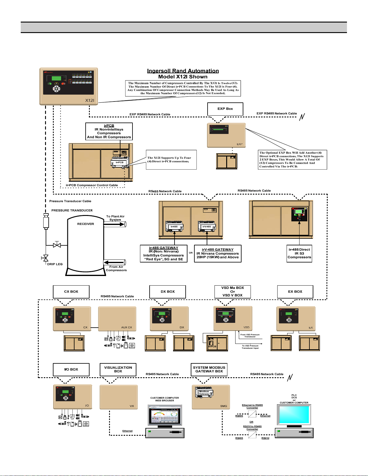
SECTION 4 — SYSTEM OVERVIEW
Refer to the X8I or X12I Operator’s Manual and the
Interconnect and Application Guide for installation
details.
4
Page 6
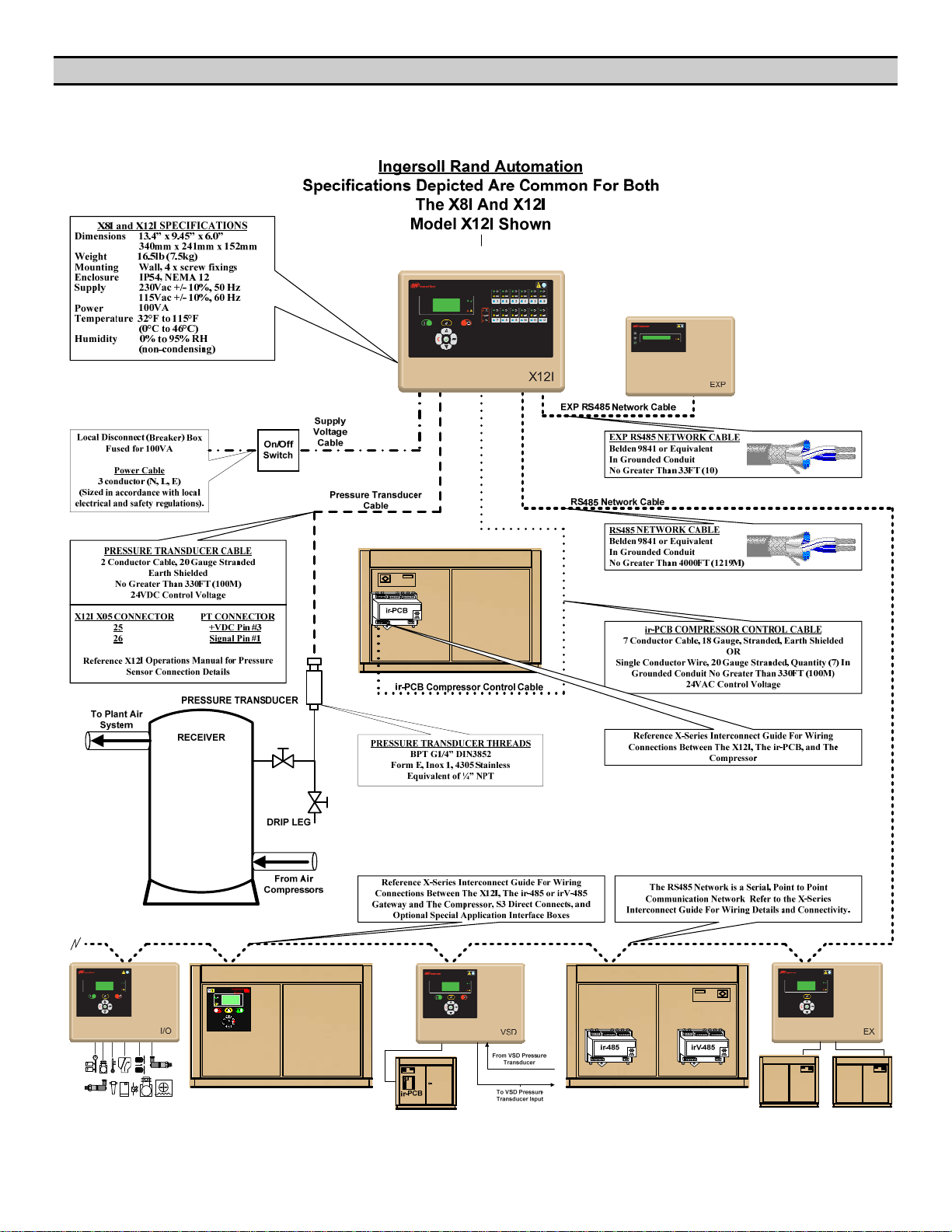
SECTION 5 — INSTALLATION OVERVIEW
Refer to the X8I or X12I Operator’s Manual and the
Interconnect and Application Guide for installation
details.
5
Page 7

SECTION 6 — BEFORE YOU START
CHECK LIST
Prior to attempting installation and commissioning of the
X8I or X12I please review the following check list:
o Quick Set Up Manual is available and has been
reviewed
o Application Guide is available and the correct
diagrams have been identified
o If the specific diagrams are not in the Application
Guide the specific compressor control wiring
schematic will be required to define the correct
interconnection
o Operator’s Manual is available and has been
reviewed
o Compressors to be connected can accept remote
load / unload commands
o Compressors to be connected have automatic
Start / Stop capability
o Correct compressor controller EPROM is installed
or available to allow Remote Control and Auto
Start/Stop (SE Controller) See Reference Table
Below.
o The correct wire is available to connect the X8I
or X12I with the Compressor / ir-PCB interface
o The correct wire is available to connect the X8I
or X12I with the Compressor / ir-485 and/or irV485 Gateway.
o The correct wire is available to connect the X8I
or X12I with the Optional Integration boxes
o The correct wire is available to connect the X8I
or X12I with the pressure sensor/transducer
o The X8I or X12I can be located within 330ft
(100m) of each compressor using the ir-PCB.
o The EXP must be located within 33ft (100m) of
X8I or X12I
o The EXP can be located within 330ft (100m) of
each compressor using the ir-PCB.
o The X8I or X12I can be located within 4000ft
(1219m) of each compressor using the ir-485
and/or irV-485 Gateway or Optional Integration
boxes. (The exception to this is connecting the
Optional EXP box to the X8I or X12I. The
maximum distance is 33ft (10m) in length.)
o The Pressure sensor/transducer can be located
appropriately within 330ft (100m) for the X8I or
X12I Controller
CHECK LIST GUIDANCE
o Electrical Drawing For Each Compressor: It is
important to have the Electrical drawing for each
compressor so that the correct interconnect
drawing can be referenced from the Interconnect
and Application Guide
o Types of Compressors To Be Sequenced: Refer
to the Interconnect and Application Guide for
specific details on the types of compressors that
can be sequenced and their individual
requirements such as Auto Restart, Intellisys
Software, etc.
o ir-PCB and ir-485 and/or irV-485 Gateway
Mounting: The ir-PCB and the Gateway module
is designed to be installed within the compressor
starter enclosure. The mounting location of the
ir-PCB should be away from any high voltage
connections, contactors, or transformers.
o ir-PCB, ir-485 and/or irV-485 Gateway and
Compressor Interconnections: Refer to the
Interconnect and Application Guide for specific
drawings for various compressors and the X8I or
X12I. If there is not a specific drawing available
for the compressor being sequenced at the site,
please contact Technical Support Services for
assistance.
o ir-PCB, ir-485 and/or irV-485 Gateway and
Compressor Interconnection Wire: The X8I or
X12I Installation kit contains 330 Ft (100m) of 18
gauge stranded wire (Orange) to use for the
connections between the ir-PCB and the
compressor. In most cases, this is sufficient for
most installations. If additional wire is required,
any 18 gauge stranded wire can be used in lieu
of the wire provided in the kit.
X8I or X12I Installation kit also contains an
interconnect cable for the connection between
the ir-485 Gateway and the Intellisys Controller.
o X8I or X12I, EXP, EX and ir-PCB Interconnect Wire:
The cable used between the X8I or X12I and the
compressor ir-PCB interconnection is designed to
use 7-conductor shielded cable or individual
wires run through earthed/grounded metal
conduit/tubing. (18 gauge wire).
o The cable used between the X8I or X12I, EXP, ir-
485 and/or irV-485 Gateway or any Optional
Integration Boxes is Belden 9841 (or equivalent).
It should be run in grounded conduit and should
not be greater than 4000 feet (1219 meters) in
length (The exception to this is connecting the
Optional EXP box to the X8I or X12I. The
maximum distance is 33ft (10m) in length.)
6
Page 8
o X8I or X12I and Pressure Transducer Wire: The
X8I or X12I and the pressure transducer
interconnection is designed to use 2-conductor
shielded cable. (18gauge)
o All external wiring to the X8I or X12I should be
made through the holes (grommets are provided)
in the X8I or X12I enclosure (8 in total). Drilling
or tapping additional holes in the enclosure can
result metal shavings making contact with the
circuit boards. Damage due to metal shavings in
the circuit boards is not covered by warranty.
o Power / Local Disconnect (Breaker): Incoming
power (115VAC/230VAC, single phase) should
be fused (100VA) and a local disconnect
provided. The power source should be regulated
and noise free. The use of a power supply
regulator might be required in applications
where unregulated power is an issue
o Confirm that all electrical connections are made
properly and tightened and conform to local
standards.
o Common Receiver: The X8I or X12I must have
its pressure transducer located in a common
receiver for proper Wet Side or Dry Side System
pressure control.
Pressure Transducer Installation: The pressure
transducer threads are BPT G1/4” DIN3852, Form
E, Inox 1, 4305 stainless. It is the equivalent of
¼” NPT.
ASSISTANCE
o Contacting Technical Support Services or Service
Bulletins listed on the IR ServiceNet can provide
further assistance if there are other questions or
concerns prior to Installation and Start-up.
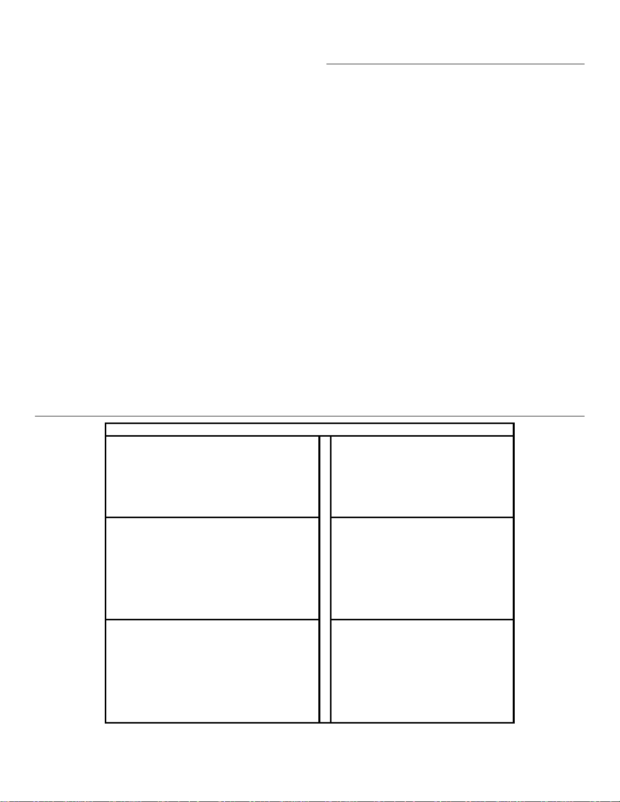
INTELLISYS CONTROLLER E-PROM REFERENCE LIST
Minimum Recommended E-prom Levels - IntelliSys Controllers
IntelliSys - First Generation "Redeye"
SSR 50 - 450HP 1 & 2 stg 2.4
Sierra 100 - 200HP 2.7
Recip 1.62
IntelliSys - Second Generation "SG" IntelliSys - Second Edition "SE"
SSR 50 - 450 1 & 2 stg 1.5 SSR 15 - 100HP 1.75
SSR 75 - 350kW ESA
Sierra 125-400HP 1.35 SSR 22 - 150kW ESA
Recip 1.28 Sierra 50 - 100HP 1.3
IntelliSys - Nirvana "SGN"
Nirvana CC 100 - 200HP 1.45
IntelliSys - Nirvana "SGNe"
Nirvana CC 50 - 300HP 2.4
1.5 SSR - UP (Pegasus) 1.23
1.93
Nirvana OF 50 - 200HP 1.2
7
Page 9
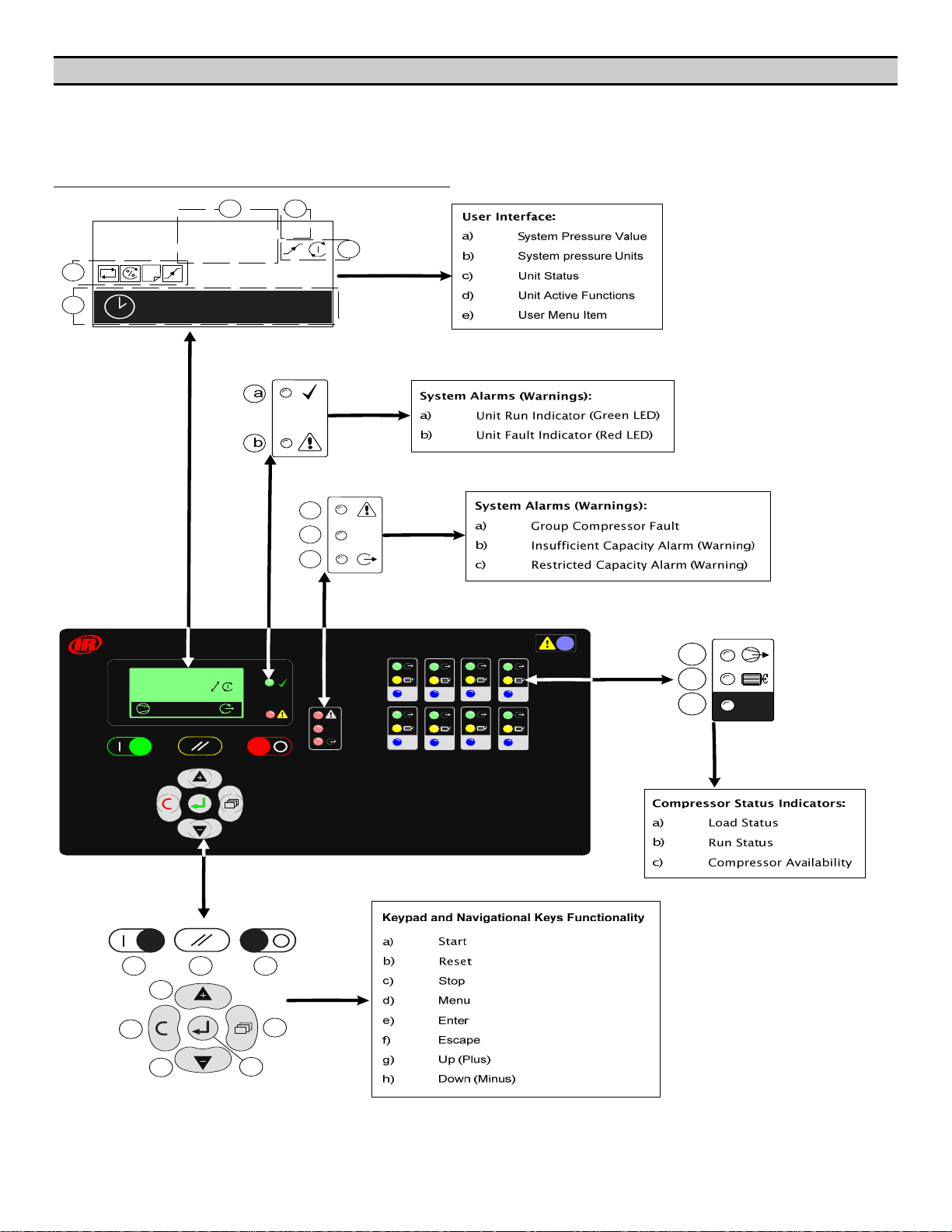
SECTION 7 — MENU NAVIGATION
The Main Display and the keypad and navigation buttons
on the X8I or X12I are depicted below and provide the
following functionality:
X8I User Interface
d
e
1
17:30 #1
a
102
b
PSI
c
a
Ingersoll Rand
1
102
A: 85%
b
c
psi
CAP
a
b
1
CAP
5
3
2
6
4
7
8
c
1
a
b
c
g
f
h
d
e
8
Page 10
1
2
3
4
9
Page 11
17:30 #1
1
#
A: 100%
102 psi
00:00 #1
10
Page 12

X8I Information Displays
P00
To view detailed information applicable to the
selected User menu display item press Enter.
Press Escape to return to the normal user menu
display items.
Real Time Clock:
P00
2
#1 18:30
T2
1
1
Shows the next Pressure Schedule event.
1: The Current Active Table
2: Day (#1=Monday, #7=Sunday)
3: Time (24hr system)
4: Table
3
4
psi
psi
psi
2
3
4
102
1
1
98
80
1: Active Table
2: Upper (Unload) Pressure Set Point
3: Lower (Load) Pressure Set Point
4: Minimum Pressure Alarm (Warning)
Sequence Rotation:
P00
#4 18:00
18 / 05 / 2006
A B C D
Items 2 and 3 show the day and time that the unit will
change to use the ‘Table’ shown in item 4.
Compressor Status:
P00
3
1
1
1
1
2
1: Compressor Number
2: Priority Setting
3: Zone Allocation Setting
4: Compressor/Connection Type
5: Maximum Capacity % Setting
6: Minimum Capacity % Setting
7: Minimum Efficiency % Setting
Item values 6 and 7 are only shown if compressor
type is IRV-485 (variable capacity/speed).
Primary Detected Pressure:
IRV-485
100 %
20 %
30 %
4
5
6
7
Day of the week (#4: Thursday), the time of
day (18:00) and the date (18/05/2006) of the next
automated sequence rotation event.
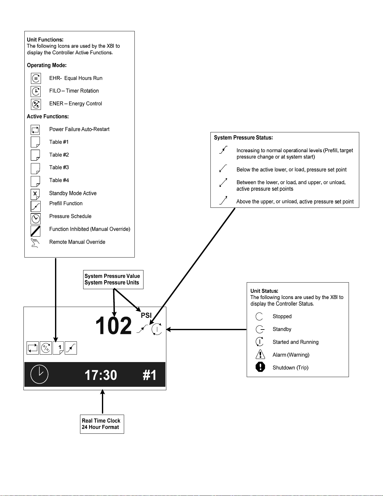
The active ‘mode’ of operation
“ABCD” The current active rotation sequence assignment.
Manual Sequence Rotation:
The sequence assignment can be manually rotated at any
time. When viewing the ‘Sequence Rotation’ information
screen press Enter:
The manual rotation symbols will appear and
flash. Press Enter again to execute a manual rotation or
Escape to abandon the manual rotation.
Automated sequence rotation is not disrupted by a
manual rotation; the next scheduled automated
sequence rotation event will still occur.
11
Page 13

X12I User Interface
d
e
1
17:30 #1
a
102
b
PSI
c
a
b
c
CAP
a
b
c
a
f
b
g
c
d
1
h
12
e
Page 14

1
2
3
4
13
Page 15

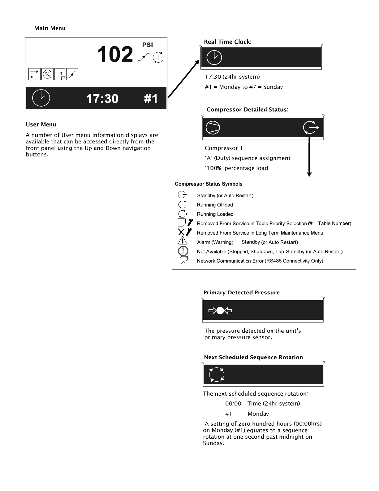
Main Menu
#
Removed From Service in Table Priority Selection
(# = Table Number)
User menu
A number of User menu information displays are
available that can be accessed directly from the front
panel using the Up and Down navigation buttons.
REAL TIME CLOCK:
17:30 #1
17:30 (24hr system)
#1 = Monday to #7 = Sunday
COMPRESSOR DETAILED STATUS:
Removed From Service in Long Term M
Menu
Removed From Service by Short Term IR-PCB
Maintenance Switch Function
Alarm (Warning)
Not Available, Shutdown (Trip), Stopped
Network Communications Error
(RS485 connectivity only)
The detailed status of each compressor in the system is
shown separately.
PRIMARY DETECTED PRESSURE:
aintenance
102 psi
The pressure detected on the unit’s primary pressure
sensor.
When using remote pressure balancing functions the
main display ‘control’ pressure may differ from the
primary detected pressure.
1
Compressor 1
‘A’ (Duty) sequence assignment
‘100%’ percentage load
Status Symbol:
Standby
Running, Offload
A: 100%
Running, Loaded
Pressure Balance Function
2ND PRESSURE INPUT:
101 psi
The second local pressure value.
Only displayed if the 2nd Pressure sensor function is
enabled.
2nd Pressure Sensor Input
14
Page 16

DIFFERENTIAL PRESSURE:
69 mBar
The differential pressure between the Primary and 2
Pressure sensor inputs.
Only displayed if the 2nd Pressure sensor function is
enabled and selected for air treatment pressure
differential monitoring.
Next Scheduled Sequence Rotation:
00:00 #1
The next scheduled sequence rotation:
nd
00:00 Time (24hr system)
#1 Monday
A setting of zero hundred hours (00:00hrs) on
Monday (#1) equates to a sequence rotation at one
second past midnight on Sunday.
2nd Pressure Sensor Input
REMOTE PRESSURE #1:
102 psi
The first remote pressure value from a remote source.
Used for the Pressure Balance Function.
Only displayed if the Pressure Balance Function is
activated and the first remote pressure has been
selected.
Pressure Balance Function
REMOTE PRESSURE #2:
100 psi
The second remote pressure value from a remote source.
Used for the Pressure Balance Function.
X12I Information Displays
To view detailed information applicable to the
selected User menu display item press Enter.
Press Escape to return to the normal user menu
display items.
REAL TIME CLOCK:
P00
2
#1 18:30
T2
1
1
Shows the next Pressure Schedule event.
1: The Current Active Table
2: Day (#1=Monday, #7=Sunday)
3: Time (24hr system)
4: Table
3
4
Only displayed if the Pressure Balance Function is
activated and the second remote pressure has been
selected.
Pressure Balance Function
15
Items 2 and 3 show the day and time that the unit
will change to use the ‘Table’ shown in item 4.
Page 17

COMPRESSOR STATUS:
P00
3
IRV-485
DIFFERENTIAL PRESSURE:
P00
4
1.0 bar
1
1
1
1
1
2
1: Compressor Number
2: Priority Setting
3: Zone Allocation Setting
4: Compressor/Connection Type
5: Maximum Capacity % Setting
6: Minimum Capacity % Setting
7: Minimum Efficiency % Setting
Item values 6 and 7 are only shown if compressor
type is IRV-485 (variable capacity/speed).
PRIMARY DETECTED PRESSURE:
100 %
20 %
30 %
5
6
7
P00
psi
psi
psi
2
3
4
102
1
1
98
80
30 sec
P2(SYS)
1: Alarm (Warning) Level
ime 2: Alarm (Warning) Delay T
3: Source of 2nd Pressure
Only show if the 2nd pressure sensor is activated in
air t
reatment pressure differential mode.
1ST REMOTE PRESSURE:
2
3
P00
B01
1: Source of 1
Only show if pressure balancing function active.
st
Remote Pressure
1
1: Active Table
2: Upper (Unload) Pressure Set Point
3: Lower (Load) Pressure Set Point
4: Minimum Pressure Alarm (Warning)
16
Pressure Balance Function
Page 18

2ND REMOTE PRESSURE:
P00
B02
1: Source of 2
Only show if pressure balancing function active and
nd
2
remote pressure in use.
Pressure Balance Function
SEQUENCE ROTATION:
nd
Remote Pressure
1
P00
#4 18:00
18 / 05 / 2006
A B C D
Day of the week (#4: Thursday), the time of
day (18:00) and the date (18/05/2006) of the next
automated sequence rotation event.
The active ‘mode’ of operation
“ABCD” The current active rotation sequence assignment.
MANUAL SEQUENCE ROTATION:
The sequence assignment can be manually rotated at any
time. When viewing the ‘Sequence Rotation’ information
screen press Enter:
The manual rotation symbols will appear and
flash. Press Enter again to execute a manual rotation or
Escape to abandon the manual rotation.
Automated sequence rotation is not disrupted by a
manual rotation; the next scheduled automated
sequence rotation event will still occur.
17
Page 19

X8I and X12I Indicators
COMPRESSOR STATUS INDICATORS:
INDICATOR LED’S
The X8I or X12I Indicator LED’s are as follows.
Off
On
Intermittent:
1sec
Slow Flash:
1sec
Fast Flash:
1sec
UNIT INDICATORS
Unit Run Indicator (Green LED)
OFF – Not Active, Stopped
a
b
c
Each compres r in the system has a set of dedicated
status indicators. The indicators will continuously show
the status of each compressor at all times.
a) Load Status
ON – Loaded
b) R un Status
OFF – Not Running
c) Available (Started)
1
so
OFF – Not Loaded, Offload
Slow Flash – The compressor has been requested
to load but is not loaded (load or re-load delay
period)
Slow Flash – The compressor has been requested
to load but is not running (blowdown delay or
other start delay)
ON – Running
OFF – No Compressor Connected
Fast Flash – Not Available, Shutdown Fault or
Stopped
Slow Flash: Active, Standby Mode
ON – Active, Running
Unit Fault Indicator (Red LED)
Fast Flash: Shutdown (Trip)
Slow Flash: Alarm (Warning)
The X8I or X12I fault indicator does not indicate
compressor fault states; see Compressor Status
Indicators.
Slow Flash – Alarm (Warning)
Intermittent Flash – The compressor has been
intentionally removed from service.
Available, OK
18
Page 20

SYSTEM ALARMS (WARNINGS):
a
b
CAP
c
a) Group Compressor Fault
OFF – All Compressors OK
The X8I or X12I will hold each compressor in an
offload state. If the compressor is equipped with a main
motor run-on-time function the compressor will run
offload for a period of time and then stop in to a
‘standby’ or ‘auto restart’ state.
The design of some air compressor control systems
may inhibit automatic transfer of pressure regulation
control to local operation mode. In this instance the
compressor will not continue production of compressed
air – consult the air compressor manual or your air
compressor supplier / specialist for details before
installing the X8I or X12I.
Fast Flash – One or more compressors Not
Available, Shutdown Fault or Stopped
Slow Flash – One or more compressors Alarm
(Warning)
b) Insufficient Capacity Alarm (Warning)
On – Insufficient Capacity
c) Restricted Capacity Alarm (Warning)
Slow Flash – Restricted Capacity
Compressor Identification
Each compressor connected to the X8I or X12I will have a
unique assigned compressor identification number;
starting at compressor 1 increasing sequentially to the
number of compressors connected to the X8I or X12I.
A: 85%
1234
START:
To start the X8I or X12I press Start.
If the ‘Start Function’ is enabled there will be a period of
time before any compressor is requested to load.
Start Function
To manually skip the Start function, press and hold
Start for several seconds.
If the Prefill function is enabled, and system pressure is
below the set prefill pressure, the system will enter Prefill
mode for the set Prefill time.
Prefill
To manually skip the Prefill function, press and hold
Start for several seconds.
When Prefill is complete, if applicable, the X8I or X12I will
enter normal operating mode.
The X8I or X12I will operate in accordance with the
parameters and options set in the active ‘Table’.
Tables
X8I & X12I Control Keypad Functions
Stop:
To stop the X8I or X12I press Stop.
The X8I or X12I will respond dependant on the setup of
item ‘CF’ in menu S02:
Pressure regulation control is automatically
transferred back to each compressor. The compressor(s)
will continue to operate using the pressure settings
programmed or set in the individual compressor
controller(s).
19
Each compressor in the system must be started
(running or in a standby or auto restart condition) before
X8I or X12I control of the compressor can be established.
The X8I or X12I will not start a compressor that is in a
stopped condition.
POWER FAILURE AUTO-RESTART
If the power failure auto-restart function is enabled
the X8I or X12I will automatically start, when power is
restored after a disruption or failure, if the X8I or X12I
was in a ‘started’ state when the power disruption or
failure occurred.
The X8I or X12I will not automatically restart if the X8I or
X12I was in a stopped state when the power disruption
or failure occurred.
Page 21

FAILURE MODE
If the X8I or X12I experiences a disruption to normal
control, or an X8I or X12I shutdown fault occurs,
pressure regulation control is automatically transferred
back to each compressor. The compressor(s) will
continue to operate using the pressure settings
programmed or set in the individual compressor
controller(s).
RESET
To reset an X8I or X12I Alarm (Warning) or
Shutdown condition press Reset.
Compressor Alarm (Warning) conditions are
automatically reset when the condition has been resolved
and reset on the compressor.
Compressor Not Available (Shutdown, Trip) conditions
are automatically reset when the condition has been
resolved and reset on the compressor; and the
compressor has been restarted.
20
Page 22

SECTION 8 — QUICK SETUP COMMISSIONING
When commissioning the X8I or X12I, carry out the
following procedures before attempting to start. It is
recommended that an authorized and trained Service
Technician performs the commissioning.
The Quick Setup Manual allows the user to enter the
basic required parameters to quickly start sequencing
the compressors with the X8I or X12I. Once sequencing
and basic control is established, the user can refer to the
Operator’s Manual for more detailed information on
other features and functionality of the unit.
PHYSICAL CHECKS
1. Before applying power to the X8I or X12I, ensure
that the power supply connections are correct
and secure and that the operating voltage
selector is set correctly for the power supply
voltage in use: 115Vac or 230Vac (+-10%),
50/60Hz.
2.
Open the front panel of the X8I or X12I and
check the location of the link wire(s) connected
to the “Voltage Selection” terminals of the power
supply PCB. If necessary, change the link wire
locations to those illustrated for the voltage in
use.
See the INSTALLATION section in the
Operator’s Manual for more information.
3. Switch on the power supply to the unit.
The control program identification will be displayed for a
short period followed by the normal operational user
display.
QUICK SET-UP CONFIGURATION
Before successful basic operation can be established the
following items must be set (in the order shown) to suit
installation requirements. The X8I or X12I can easily be
commissioned by simply setting the following
parameters.
NOTE: Leave all other parameters at factory defaults.
S02 - NC Number of Compressors
S02 - PM Maximum Pressure Alarm
S01 - Ct Real Time Clock Set
(X8I) C03 – 01/8 Compressor #1-8 Configurations
(X12I) C03 – 01/12 Compressor #1-12 Configurations
(X8I) C01 - 01/8 Compressor #1-8 Running Hours
(X12I) C01 - 01/12 Compressor #1-12 Running Hours
T01 - PH High Pressure Set Point
T01 - PL Low Pressure Set Point
T01 - Pm Minimum Pressure Alarm
(X8I) T01 – 01/8 Compressor #1-8 Priority
(X12I) T01 – 01/12 Compressor #1-12 Priority
PRESSURE DISPLAY
Check the displayed system pressure. If the pressure is
incorrect, or inaccurate, check the type and range of the
sensor and carry out the pressure sensor commissioning
and calibration procedure. If the display shows an error,
the error will need to be corrected before continuing.
See the Operator’s Manual for troubleshooting and
correcting the fault or error condition.
21
NOTE: By default, the pressure unit of measurement is
PSI. If the unit of measurement is BAR or kPA, please
refer to the Operator’s Manual for information on
changing the S02 P> Units Setting parameter.
Once set, the X8I or X12I will sequence all compressors
based on load demand using the ENER, Energy Mode.
Optional features and functions
Installation requirements may involve the
implementation of additional or optional functions and
features. Please refer to the appropriate Guide or Manual
as required.
Page 23

SECTION 9 — SYSTEM CONFIGURATION
Q
X8I or X12I Configuration Screens
T01
16 112
01 PH psi 102
02
psi
04 S
# = Table T01 to T06
T0# – PH High Pressure Set Point
The ‘upper’ or ‘unload’ pressure set point that will be
used when the ‘Table’ is active. The default setting for
this parameter is 102 PSI. The values for this
parameter are:
The highest value for the High Pressure setpoint = PM
“Maximum Pressure Alarm” minus 2 times TO
“Tolerance”.
If PM is set for 145 PSI and TO is set for 3.0 PSI, then the
highest value for the High Pressure setpoint would be
139 PSI.
The lowest value for the High Pressure setpoint = PL “Low
Pressure” setpoint plus TO “Tolerance”
If PL is set for 98 PSI and TO is set for 3.0 PSI, then the
lowest value for the High Pressure setpoint would be 101
PSI.
T0# - PL Low Pressure Set Point
The ‘lower’ or ‘load’ pressure set point that will be used
when the ‘Table’ is active. The default setting for this
parameter is 98 PSI. The values for this parameter are:
The highest value for the Low Pressure setpoint = PH
“High Pressure” setpoint minus TO “Tolerance”.
If PH is set for 102 PSI and TO is set for 3.0 PSI, then the
highest value for the Low Pressure setpoint would be 99
PSI.
The lowest value for the Low Pressure setpoint = Pm
“Minimum Pressure Alarm” setpoint plus 2 times TO
“Tolerance”
If Pm is set for 80 PSI and TO is set for 3.0 PSI, then the
lowest value for the Low Pressure setpoint would be 86
PSI...
Tables
98PL
003 Pm psi
ENER ( % )
PM
TO
P
r
e
s
s
u
r
e
Pressure Set-Point Illustration Summary
T0# - Pm Minimum Pressure Alarm
The miniumum pressure ‘Warning’ or ‘Alarm’ level that
will be used when the ‘Table’ is active. The default
setting for this parameter is 80 PSI. The values for this
parameter are:
The lowest Minimum Pressure Alarm setpoint = “The
minimum range of the pressure transducer used.“
The highest Minimum Pressure Alarm setpoint = “The
value from the Table PL – Low Pressure Setpoint” minus 2
times TO “Tolerance””
If PL in Table 1 (T01) is set for 100 PSI and TO is set for
3.0 PSI, then the highest Minimum Pressure setpoint
would be 94 PSI.
T0# - 01 Compressor #1 Priority
The ‘priority’ setting for compressor number 1 that will
be used when the table is active.
To
‘n’
T0# -
The ‘priority’ setting for compressor number ’n’ that will
be used when the table is active.
‘n’
maximum number of compressors for the X8I and 12 is
the maximum number of compressors for the X12I.
The default setting for this parameter is 1.
is active by selecting “X” priority. The compressor will be
held offload and will not be utilized under any
circumstances.
Compressor #’n’ Priority
= number of compressors in the system. 8 is the
Priority Settings:
: compressor(s) can be inhibited from use while a table
TO
PH + TO
PH
PT
PL
PL - TO
Pm
22
Page 24

A
06
BL
S01
08 Ct 1 . 18:00
08
PS
08
08
R
RP
1 . 00:00
5
X
12
ER
01 P>
02
NC
03
PM
04
CF
S02
X
psi
4
145
X
psi
Features and Functions
S01 - Ct Real Time Clock Set
Adjustment for the internal real time clock.
(Hours, Minutes, Date, Month, Year)
The ‘Day of the Week’ (1= Monday to 7=Sunday) is
automatically calculated and set in accordance with the
Day, Month and Year. The default setting for this
parameter is - --.--. (Represents the clock has not
been initialized))
The values for this parameter are:
“1” to “7” the ‘Day of the Week’ (1= Monday to
7=Sunday) which is automatically calculated and set
in accordance with the Day, Month and Year entered.
“00” to “23” the Hour for the Real Time Clock.
“0” to “59” the Minutes for the Real Time Clock.
“1” to “31” the Day for the Real Time Clock.
“1” to “12” the Month for the Real Time Clock.
“2005” to “2100” the Year for the Real Time Clock.
Pressure Control; Tables
S02 - NC Number of Compressors
This parameter sets the number of compressors
connected to, and controlled by, the X8I or X12I. This
value must be set to match the system at commissioning.
The default setting for this parameter is 4. The values
for this parameter are:
“1” for 1 compressor
To
“8” for 8 compressors (X8I)
“12” for 12 compressors (X12I)
S02 - PM Maximum Pressure Alarm
This parameter sets the High pressure ‘Fault’ level. This
value remains active at all times and is the same for all
‘Tables’. It should be set just below system pressure
relief value(s) and below the maximum system pressure
rating of all air system components. The default setting
for this parameter is 145. The values for this
parameter are:
The highest value for the Maximum Pressure Alarm
setpoint = “The maximum range of the pressure
transducer used”
The lowest value for the Maximum Pressure Alarm
setpoint = “The highest value from any Table “PH Pressure High” Setpoint plus 2 times the “To –
Tolerance”
If PH in Table 1 (T01) is set for 100 PSI, and PH
in Table 2 (T02) is set for 110 and TO is set for
3.0 PSI, then the lowest Maximum Pressure
setpoint would be 116 PSI.
23
Page 25

Control - Equal Hours Run Mode
C01 – 01 to C01 – ‘n’ Run Hours’
‘n’
= number of compressors in the system. 8 is the
maximum number of compressors for the X8I and 12 is
the maximum number of compressors for the X12I.
This parameter is set to match the running hours of each
compressor. Record of detected ‘running’ hours for each
compressor. The run hours value can be manually
adjusted, at any time, to match the running hours
meter/display value of each compressor. The default
setting for this parameter is 0 hours. The values for
this parameter are:
“0 to x” where x = the actual run hours for the
compressor
Installation – Compressor Connections
’
C03 – 01 to C03 – ‘n
‘n’
= number of compressors in the system. 8 is the
maximum number of compressors for the X8I and 12 is
the maximum number of compressors for the X12I
This parameter sets the type, method of connection, and
the control functionality, of each compressor connected
to the X8I or X12I. The default setting for this
parameter is ir-PCB.
Dependant on the regulation and connection type
selected the set-up screen will change to show applicable
settings.
Compressor Connection’
24
Page 26

X8I or X12I Compressor Connectivity and
Functional Settings
ir-PCB:
C03
1
2
irV-PCB:
C03
1
IRV-PCB
2
ir-485:
C03
1
01.01
1
IR-PCB
10 s
01.01 01
1
10 s
01.01
1
IR-485
01
100 %
+V=!
100 %
+V=!
10 s
01
100 %
5
4
5
4
3
5
1
Compressor Connectivity:
ir-PCB
Fixed speed, load/unload; connected to X8I OR
X12I using ‘ir-PCB’ module using 6-wire method.
(0/100%) 0% or 100% regulation
irV-PCB
using ‘ir-PCB’ module using the 7-wire ‘V’ terminal
method.
ir-485
X12I on RS485 network.
IrV-485
X12I on RS485 network.
2
Set to match the time that the compressor takes to start
its main motor and load. This time will typically be
equivalent to the compressors ‘Star/Delta’ time.
If unknown, the time can be established by experiment;
manually start the compressor, from a stopped
condition, and determine the time from pressing the
start button until the compressor loads and contributes
capacity output to the system.
of multiple compressors and other operational
calculations. An accurate time is important for successful
unit operation.
3
Variable Speed; connected to X8I OR X12I
(variable speed regulation)
Fixed speed, load/unload; connected to X8I OR
(0/100%) 0% or 100% regulation
Variable Capacity/Speed; connected to X8I OR
(0 . . 100%) variable %Load regulation
Compressor Start Sequence Time:
This time is used by the unit for ‘staggered starting’
Compressor Run-On Stop Time:
2
irV-485:
1
2
25
C03
IRV-485
10 s
01.01
1
10 s
01
100 %
50 %
60 %
5
6
7
This setting is only applicable to ‘irV-PCB’
connectivity and is not displayed for other connectivity
options.
The time that the compressor main motor will continue
to run when the compressor is offload (main motor runon-time).
If unknown, the time can be established by experiment;
start and load the compressor then arrange a condition
that will unload the compressor for a period of time.
Determine the time from the moment the compressor
unloads until the main motor stops and the compressor
enters a ‘Standby’ or ‘Auto Restart’ condition.
This time is used by the X8I or X12I for accurate
recording of ‘run hours’ (EHR mode), operational
calculations and other data recording applications. An
accurate time is important for successful X8I or X12I
operation.
Page 27

4
ir-PCB Alarm (Warning) Input:
Only applicable for ir-PCB connectivity. Not shown
for ‘485’ network types.
For ‘ir-PCB’ connectivity applications the voltage
detection function for the ‘ir-PCB’ Alarm (Warning) input
can be inverted.
+V=! An Alarm (Warning) condition is generated if the
‘ir-PCB’ Alarm input detects a voltage between 12250Vac/dc (default).
0V=! An Alarm (Warning) condition is generated if the
‘ir-PCB’ Alarm input detects no voltage.
5
% Maximum Output Capacity
The maximum output capacity of each compressor must
be set as a percentage with reference to the highest
output capacity (the largest) compressor in the system.
The highest output capacity compressor must be
assigned with 100% capacity. Equal capacity (equal sized)
compressors should be assigned the same % capacity
value. Calculate the output capacity of compressor(s) that
are smaller than the largest in the system as a
percentage of the largest in the system.
For example:
Compressor 1 700 cfm 100%
Compressor 2 700 cfm 100%
Compressor 3 420 cfm 60%
Compressor 4 420 cfm 60 %
Compressor 5 350 cfm 50%
Compressor 6 175 cfm 25%
For example 1:
For a variable speed compressor that has been assigned
a maximum capacity output percentage of 100%, and is
able to reduce speed to 30% of maximum speed:
Minimum Output Capacity = 30% (related to the largest
capacity)
Example Compressor 1 is a VSD
Max CFM = 700
Max Output Capacity 700/700 = 100%
Min CFM = 210 (30% or 700 x .30)
Min Output Capacity 210/700 = 30% (or 30% x 100%
= 30%)
For example 2:
For a variable speed compressor that has been assigned
a maximum capacity output percentage of 60% (related
to the largest capacity), and is able to reduce speed to
30% of maximum speed:
Example Compressor 4 is a VSD:
Max CFM = 420
Max Output Capacity 420/700 = 60%
Min CFM = 127 (30% or 420 x .30)
Min Output Capacity 127/700 = 18% (or 30% x 60% =
18%)
For example 3:
For a 3-step (0/50/100%) reciprocating compressor that
has been assigned a maximum capacity output
percentage of 60%, the minimum output capacity is the
half-output regulation step:
Minimum Output Capacity = 30%
6
% Minimum Output Capacity
Only applicable for a variable output compressor
(IRV-485). Not shown for other types.
The minimum output capacity of a variable output
compressor must be set as a percentage of the
compressor’s maximum output scaled in accordance
with the % maximum capacity output value. Minimum
output capacity is regarded as the output capacity at the
lowest possible speed (variable speed compressor) or the
minimal output achievable (stepping or other variable
regulation control).
26
Page 28

7
% Minimum Efficiency
Only applicable for a variable output compressor
(IRV-485). Not shown for other types.
The minimum efficiency point is regarded as the speed,
or step, below which another smaller capacity
compressor in the system could achieve the equivalent
output at a higher efficiency.
The percentage value is directly related, and scaled, to
the maximum and minimum output percentage values.
For example:
Example: A Compressor is a VSD:
Max CFM = 420 (Largest Compressor is 700 CFM)
Max Output Capacity 420/700 = 60%
Min CFM = 127 (30% or 420 x .30)
Min Output Capacity 127/700 = 18% (or 30% x 60% =
18%)
If another compressor in the system is able to provide
40% of the compressor’s full speed output more
efficiently, set the % Minimum Efficiency value to 24%
(40% x 60%). This percentage value represents 40% of the
full speed output of the compressor scaled to System
capacity.
When the compressor is detected as operating below the
% Minimum Efficiency value for a period of time the X8I
AND X12I will immediately re-evaluate utilization and reconfigure, if possible, to utilize a the smaller capacity,
more efficient compressor, or combination of
compressors. This process is automatic and executed
dynamically in accordance with prevailing operational
conditions at the time. The ENER control mode
algorithms will eventually conclude the best compressor
fit without this parameter; the % Minimum Efficiency
input will speed up this process.
The intent of this feature is to always operate the
smallest, most efficient compressor and to prevent a
variable output capacity compressor operating at
minimal speed, or minimal output, for prolonged periods
of time. Generally a variable output compressor
operating at minimal capacity is less efficient than a
smaller capacity compressor that is able to achieve the
same output at higher, or maximum, output capacity.
27
Page 29

SECTION 10 WIRING DIAGRAMS
Refer to the appropriate Manual for more detail on
the specifics for each of the followings components.
X8I, EXP, EX, VSD MA, VSD V, I/O, CX, DX,
SMG Power Supply Connection
N L
2 3 1 4
E
XPM-TAC24
X04
EE L N
X01
X04
2 3
1
VOLTAGE SELECT
1
2 3 4
VOLTAGE SELECT
4
230Vac
115Vac
X12I Power Supply Connection
XPM-TAC24
1
X04
X04
234
VOLTAGE SELECT
1
234
VOLTAGE SELECT
230Vac
115Vac
X8I, X12I Pressure Transducer Connection
Wire polarity is important.
Pressure Sensor Wiring and Location
28
Page 30

X8I, X12I RS485 Connection
X06
L2
L1
30
29
28
27
RS485
X8I to EXP RS485 Connection
L2
L1
EX Box RS485 Connection
X07
28
27
26
25
RS485
L1
L2
VSD Ma, VSD V Box RS485 Connection
L2
L1
X07
L2
L1
I/O Box RS485 Connection
X07
28
27
26
25
RS485
L1
L2
C1-4
X01
L1 L2
XPM485
C5-8
X06
29
28 3027
L1
L2 L2L1
X12I to EXP RS485 Connection
XPM-LED
X01
CX Box RS485 Connection
X07
L1
L2
RS485
DX Box RS485 Connection
X07
L1
L2
30
29
28
27
RS485
L1
L2
L1
L2
C1-4
X01
L1 L2
XPM485
XPM-LED
X01
C5-8 C9-12
X06
29
28 3027
L1
L2 L2L1
33ft (10m) max
28 3027
L2 L2L1
X06
29
L1
29
Page 31

Ir485, irV485 Gateway Connection
-24VDC
+24VDC
NC
-V +V
OUTPUT
24VDC 0.3A
idec
DC ON
V.ADJ
7.5
OUTPUT
W
POWER SUPPLY
PS5R-A24
50/60HZ
INPUT
100/240 VAC 0.17A
L
N
LNG
From Compressor
110 / 230VAC
+24VDC
0VDC
ir-485 / irV485
X01
+24VDC
-24VDC
12
+
Power Supply
X01
-
ir 485 Gateway
For IntelliSys “Red Eye”, SG and SE equipped with an RJ11
RS485 data communications connection port, use the
RJ11 Modbus cable supplied with the ir-485 Gateway.
RJ11
2
4
2
3
4
5
L1 (2)
1
2
3
4
5
L2 (4)
6
M4
Ring Tag
L1
L2
X02
irV-485 Gateway
For IntelliSys SGN, SGNe and Nirvana 15-30kW (20-40HP)
equipped with a Phoenix RS485 data communications
connector, use the RJ11 Modbus cable supplied with the
irV-485 Gateway and modify as shown by removing the
RJ11 Plug.
Intellisys Controller Connection
X8I, X12I RS485 Connection
L1
L2
X02
M4
Ring Tag
L2
L1
1
2
SGN / SGNe Phoenix
6Pin Connector
2
1
Consult the air compressor manual or your air
compressor supplier/specialist for details before
installing the X12I.
Consult the X-Series Interconnect and Application
Guide prior to the installation of the X12I and the ir-485
& irV-485 to the air compressor.
Consult the ir-485 & irV-485 Gateway Instruction
Manual for information regarding the use of the ir-485 &
irV-485 Gateway.
30
Page 32

ir-485 Gateway Switch Settings
Compressor Identification Number
Each compressor connected to the X8I or X12I will have a
unique assigned compressor identification number;
starting at compressor 1 increasing sequentially to the
number of compressors connected to the X8I or X12I.
Switch SW1 is used to assign this unique address on the
ir-485 Gateway
SW1
SW2 SW3
Compressor Type
Each compressor connected to the X8I or X12I must be
matched to a specific type and functionality. This is
unique to every compressor and the associated controller
used on it. Switch SW2 is used to assign this unique type
and functionality on the ir-485 Gateway
SW1
SW2
SW3
System Network Address
1 7
2 8
3 9 (for X12I only)
4 10 (for X12I only)
5 11 (for X12I only)
6 12 (for X12I only)
Function Selections
SW1 SW2
SW3
IR-BUS (9600 N-8-2)
0: SSR
1: SE_15_100
2: SE_PEGASUS (UP Series)
3: SE_ESA_22_150
4: not used 5: not used
6: not used 7: not used
8: SSR_PHASE_1 (status register only)
10: SIERRA_SE_50_100
11: SIERRA_125_200
SW3-2 to 4 are not used.
SW3-1: Software Version Display
31
MODBUS (9600 N-8-1)
9: SSR_SG
12: SIERRA_125_400
13: SIERRA_SG_BOOSTER
14: not used 15: not used
Page 33

irV-485 Gateway Switch Settings
Compressor Identification Number
Each compressor connected to the X8I or X12I will have a
unique assigned compressor identification number;
starting at compressor 1 increasing sequentially to the
number of compressors connected to the X8I or X12I.
Switch SW1 is used to assign this unique address on the
ir-485 Gateway
SW1
SW2 SW3
Compressor Type
Each compressor connected to the X8I or X12I must be
matched to a specific type and functionality. This is
unique to every compressor and the associated controller
used on it. Switch SW2 is used to assign this unique type
and functionality on the irV-485 Gateway
SW1
MODBUS (9600 N-8-1)
SW2
SW3
System Network Address
1 7
2 8
3 9 (for X12I only)
4 10 (for X12I only)
5 11 (for X12I only)
6 12 (for X12I only)
Function Selections
SW1 SW2
SW3-3 is not used.
SW3
0: NIRVANA_SGN
1: NIRVANA_SGNe
2: NIRVANA 20-40HP
IR-BUS (9600 N-8-2)
3: RECIP
4: RECIP_SG
5: RECIP_BOOSTE R
6: not used 7: not used
8: not used 9: not used
10: not used 11: not used
SW3-1: Software Version Display
SW3-2: Learning Mode
SW3-4: Nirvana 50HP and Greater 1psi Target
Offset Pressure
32
12: not used 13: not used
14: not used 15: not used
Page 34

irPCB Connection SMG Box RS485 Connection
C01 C02 C04
i-PCB
#1
C03
V
24613 5
C05
LED 1 LED 2
V
X01
246135
V1
Consult the air compressor manual or your air
compressor supplier/specialist for details before
installing the X12I.
Consult the X-Series Interconnect and Application
Guide prior to the installation of the X12I and the ir-PCB
to the air compressor.
3
2
1
X02
L2
L1
MODBUS
RS485
Customer Modbus Connection
X8I, X12I RS485 Connection
L1
(B)L2
(A)
Consult the ir-PCB Instruction Manual for
information regarding the use of the ir-PCB.
33
Page 35

VX Box Connection
VX Box Power Supply Connection
34
 Loading...