

Page 1

Before installing or starting this unit for the first time, this
manual should be studied carefully to obtain a working
knowledge of the unit and/or the duties to be performed
while operating and maintaining the unit.
RETAIN THIS MANUAL WITH UNIT. This Technical
manual contains IMPORTANT SAFETY DATA and
hould be kept with the unit at all times. s
More Than Air, Answers.
Online answers: http://www.air.irco.com
Ingersoll Rand
System Automation
X12I
Operator’s Manual
C.C.N. : 80445075
REV. A
DATE DECEMBER 2008
Page 2

TABLE OF CONTENTS
TABLEOFCONTENTS..................................................2
SECTION1—INTRODUCTION....................................3
SECTION2—SAFETYPRECAUTIONS...........................3
INSTALLATION.................................................................3
OPERATION....................................................................3
SERVICEMAINTENANCEANDREPAIR...................................4
SECTION3—COMPRESSORCONNECTIONAND
CONTROL...................................................................5
COMPRESSORCONNECTION..............................................5
STANDARDCONNECTIONMETHODS...................................5
OPTIONALCONNECTIONMETHODS....................................6
PRESSUREDETECTIONANDCONTROL.................................10
X12IMAINDISPLAYOVERVIEW.........................................11
X12ISYSTEMOVERVIEW.................................................12
X12IINSTALLATIONOVERVIEW.........................................13
SECTION4—INSTALLATION....................................14
UNITLOCATION............................................................14
POWERSUPPLY.............................................................14
PRESSURESENSORLOCATION..........................................15
PRESSURESENSORCONNECTION......................................15
IR‐485ANDIRV‐485GATEWAYMODULE.........................16
IR485COMMUNICATIONPROTOCOL.................................16
RS485NETWORK.........................................................16
COMPRESSORINTERFACEIR‐PCB.....................................18
IR‐PCBEXPBOX(OPTION).............................................18
ONBOARDI/OOPTIONS..................................................19
SECTION5—CONTROLFEATURESANDFUNCTIONS.21
PRESSURECONTROL.......................................................21
ANTI‐CYCLINGCONTROL..........................................21
TOLERANCE..............................................................22
DAMPING.................................................................22
SYSTEM
VOLUME......................................................23
SEQUENCECONTROLSTRATEGIES.....................................24
S
TANDARDCONTROLFEATURESANDFUNCTIONALITY..........24
ALTERNATECONTROLSTRATEGIES.....................................28
ADDITIONALCONTROLFEATURESANDFUNCTIONALITY..........29
SECTION6—DISPLAYANDMENUOPERATION........31
SERMENU.................................................................33
U
NFORMATIONDISPLAYS.................................................34
I
INDICATORLED’S..........................................................36
COMPRESSORIDENTIFICATION.........................................37
X12ICONTROLKEYPADFUNCTIONS.................................37
SECTION8—SYSTEMCONFIGURATION...................40
DISPLAYITEMSTRUCTURE................................................40
ACCESSINGTHEX12ICONFIGURATIONSCREENS....................40
USERLEVELMENUS.......................................................42
SERVICELEVELMENUS(0021)........................................43
HIGHLEVELMENUS(0032)............................................44
X12ICONFIGURATIONSCREENS.........................................45
X12ICOMPRESSORCONNECTIVITYANDFUNCTIONALSETTINGS
..................................................................................56
SECTION9‐VIRTUALRELAYAUTOMATION..............59
VIRTUALRELAYCONFIGURATION......................................62
FUNCTIONLISTS.............................................................67
VIRTUALRELAYAUTOMATIONEXAMPLES...........................71
SECTION10—DIAGNOSTICS....................................73
SECTION11—X12IFAULTINDICATIONS..................77
ERRORLOG...................................................................77
FAULTCODES.................................................................78
INTERNALCONTROLLERFAULT‘E’CODES.............................79
SECTION12—PARTSLIST........................................80
SECTION13—TECHNICALDATA..............................80
SECTION14—WIRINGDIAGRAM............................81
X12ISCHEMATIC...........................................................81
X12IXPM‐AI4&XPM‐DI8R4......................................82
X12ITERMINALPCB.....................................................83
XPM‐TAC24...............................................................84
SECTION15—COMMISSIONINGFORM...................85
NOTES.....................................................................91
Refer to Section Indicated
Note
Important or Caution, Safety
SECTION7—COMMISSIONING................................39
PHYSICALCHECKS..........................................................39
PRESSUREDISPLAY........................................................39
X12IQUICKSET‐UPCONFIGURATION...............................39
OPTIONALFEATURESANDFUNCTIONS...............................39
2
Page 3
SECTION 1 — INTRODUCTION
The X12I is an advanced system controller designed to
provide safe, reliable, and energy-efficient management
of your compressed air system. The X12I is capable of
controlling up to twelve (12) positive displacement air
compressors. The compressors may be fixed speed,
variable speed or multi-step and have electro-pneumatic
or microprocessor based controls.
SECTION 2 — SAFETY PRECAUTIONS
ALWAYS EMPLOY SAFE WORKING PRACTISE
AND PROCEDURES
WARNING: Risk of Danger
WARNING: Risk of Electric Shock
WARNING: Risk of High Pressure
WARNING: Consult Manual
Before installing or operating the product, take time to
carefully read all the instructions contained in this
manual, all compressor manuals, and all manuals of any
other peripheral devices that may be installed or
connected to the unit.
When installing, commissioning, operating or carrying out
service or maintenance on a product, personnel must use
safe working practice and observe all relevant local
health and safety requirements and regulations.
Electricity and compressed air have the potential to
Lethal voltages are used within the product. Use extreme
caution when carrying out electrical checks. Isolate the
power supply before starting any maintenance work.
Maintenance must be performed by adequately qualified
personnel that are equipped with the proper tools. If the
user employs an operating procedure, an item of
equipment, or a method of working which is not
specifically recommended, the user must ensure the
product will not be damaged or made unsafe and that
there is no risk to persons or property.
It is not possible to anticipate every circumstance that
might represent a potential hazard. Failure to observe
safety precautions or implement safe working practices
may be considered dangerous practice or misuse of the
roduct. p
ere personal injury or property damage cause sev
The X12I is uniquely configurable and customizable to
meet the specific needs of some of the most complex
compressed air system. Additionally, the X12I control
network can expand to include monitoring and control of
arious compressed air system components. v
INSTALLATION
Installation work must only be carried out by a competent
n under qualified supervision. perso
A fused isolation switch must be fitted between the main
wer supply and the product. po
The product should be mounted in such a location as to
allow operational and maintenance access without
obstruction or hazard and to allow clear visibility of
ators at all times. indic
If raised platforms are required to provide access to the
product they must not interfere with normal operation or
obstruct access. Platforms and stairs should be of grid or
late construction with safety rails on all open sides. p
OPERATION
The product must only be operated by competent
nnel under qualified supervision. perso
Never remove or tamper with safety devices, guards or
nsulation materials fitted to the unit. i
The product must only be operated at the supply voltage
and frequency for which it is designed.
When mains power is switched on, lethal voltages are
present in the electrical circuits and extreme caution must
be exercised whenever it is necessary to carry out any
work on the unit.
Do not open access panels or touch electrical
components while voltage is applied unless it is
necessary for measurements, tests or adjustments. This
work must only be carried out by a qualified electrician or
technician equipped with the correct tools and
appropriate protection against electrical hazards.
All air compressors and/or other machine equipment
connected too, and controlled by, the product should
have a warning sign attached stating ‘THIS UNIT MAY
ART WITHOUT WARNING' next to the display panel. ST
If an air compressor and/or other machine equipment
connected too, and controlled by, the product is to be
started remotely, attach warning signs to the machine
stating ‘THIS UNIT CAN BE STARTED REMOTELY’ in a
prominent location, one on the outside of the machine,
he other inside the machine control compartment. t
3
Page 4

SERVICE MAINTENANCE AND REPAIR
Service, maintenance, repairs or modifications must only
be carried out by competent personnel under qualified
supervision.
If replacement parts are required use only genuine parts
from the original equipment manufacturer, or an
ative approved source. altern
Carry out the following operations before opening or
removing any access panels or carrying out any work on
• Isolate from the main electrical power supply. Lock
• Attach a label to the isolator switch and to the
Ensure that all instructions concerning operation and
maintenance are strictly followed and that the complete
product, with all accessories and safety devices, is kept
in good working order.
The accuracy of sensor devices must be checked on a
regular basis. They must be renewed when acceptable
tolerances are exceeded. Always ensure any pressure
within a compressed air system is safely vented to
atmosphere before attempting to remove or install a
The product must only be cleaned with a damp cloth,
using mild detergents if necessary. Avoid the use of any
Do not paint the control facial or obscure any indications,
controls, instructions or warnings.
uct:- the prod
the isolator in the 'OFF' position and remove the
fuses.
product stating ‘WORK IN PROGRESS - DO NOT
APPLY VOLTAGE'. Do not switch on electrical
power or attempt to start the unit if such a warning
label is attached.
evice. sensor d
ubstances containing corrosive acids or alkalis. s
4
Page 5
SECTION 3 — COMPRESSOR CONNECTION AND CONTROL
COMPRESSOR CONNECTION
Each air compressor in your system must be interfaced
to the X12I. Interface methods may vary depending on
the compressor type and/or local control configuration.
The following are main methods for interfacing
ompressors to the X12I: c
1) The ir-PCB Interface
2) The ir-485 Gateway Interface
3) The irV-485 Gateway Interf
4) Direct Connect via RS485
5) Special Application Interface
Consult the air compressor manual or your air
compressor supplier/specialist for details before installing
he X12I. t
Consult the X12I Interconnect and Application
uide
G
ace
STANDARD CONNECTION METHODS
1) The ir-PCB Interface module that is designed to
interface to any positive displacement air compressor
(regardless of make or manufacturer) with an available
c
ontrol voltage of 12-250V (either 50Hz or 60Hz).
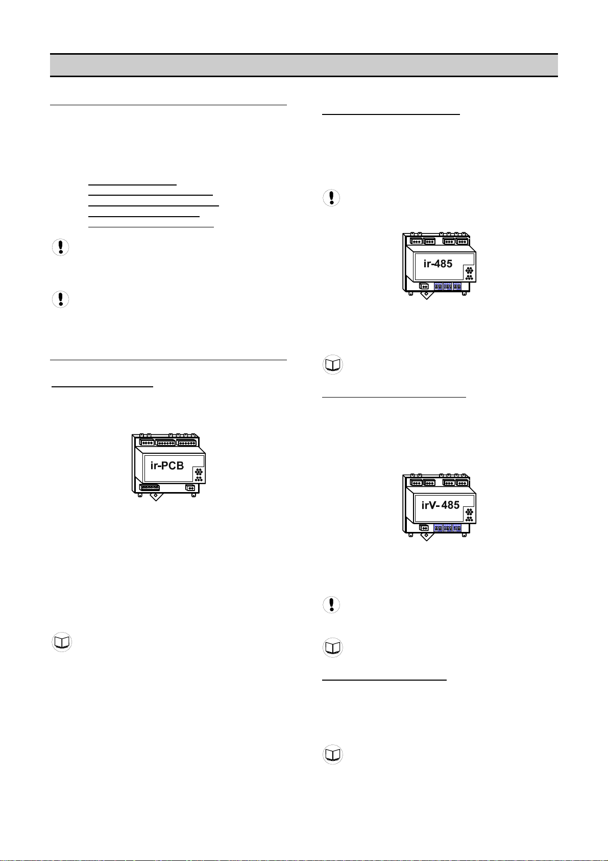
2) The ir-485 Gateway Interface
designed to interface to any Ingersoll Rand Intellisys
controlled (Non-Nirvana) compressor. The X12I
communicates to the ir-485 Gateway via a two wire,
RS485 network utilizing the ir485 protocol. All IR
compressors equipped with Intellisys controllers (Non-
irvana and Recips) require this interface.
N
All Nirvana Compressors, 20 HP (15KW) and
bove require the irV-485 Gateway.
a
The ir-485 Gateway interface module is installed within
the compressor control cabinet and connected to the
12I using Belden 9841 or equivalent RS485 cable.
X
ir-485 & irV485 Manual
3) The irV-485 Gateway Interface module that is
designed to interface to any Ingersoll Rand Nirvana
compressor. The X12I communicates to the irV-485
Gateway via a two wire, RS485 network utilizing the ir485
protocol. All Nirvana Compressors, 20 HP (15KW) and
above, and Recips, with Redeye and SG controllers,
equire this interface.
r
module that is
The ir-PCB interface module is installed within the
compressor control area and connected to the X12I using
a six (6) wire cable, (seven (7)-wire cable for Nirvana 7.5
o 15HP (5.5 to 11KW).
t
Each air compressor must be equipped with an
online/offline pressure regulation system capable of
accepting a remote load/unload signal through a volt-free
switching contact or a single electro-mechanical pressure
s
witch.
ir-PCB Manual
The irV-485 Gateway interface module is installed within
the compressor control cabinet and connected to the
12I using Belden 9841 or equivalent RS485 cable.
X
Nirvana 7.5 to 15HP (5.5 to 11KW) connect via the
-PCB using seven (7)-wire cable.
ir
ir-485 & irV485 Manual
4) Direct Connect via RS485
compressor (R-Series) that has an integrated RS485
network port utilizing the ir485 protocol. The X12I
communicates to these compressors via a two wire,
RS485 network. The compressor is connected to the
12I using Belden 9841 or equivalent RS485 cable. X
R-Series Manual
to any Ingersoll Rand
5
Page 6
OPTIONAL CONNECTION METHODS
5) Special Application Interface uses integration boxes
designed to accommodate various types of compressor
nd regulation methods and system monitoring. a
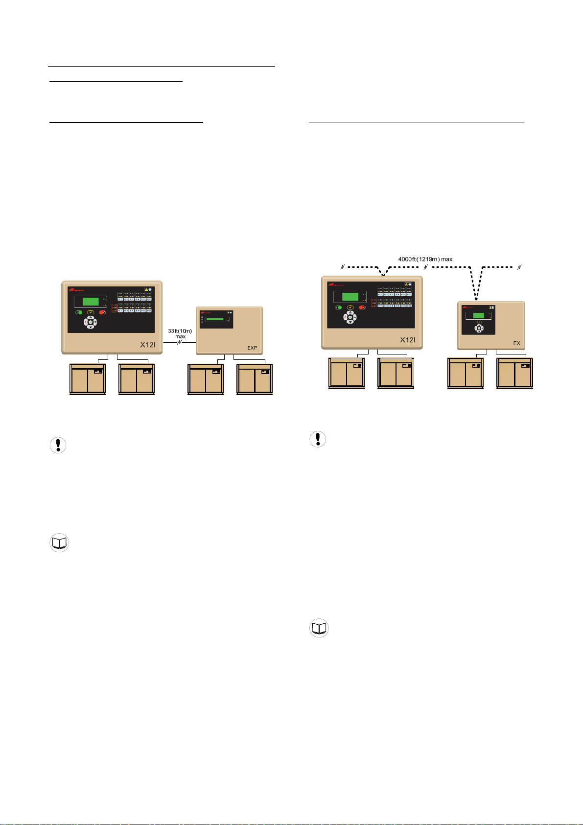
Expansion Module: EXP Box (Option)
As standard the X12I has four direct connect ‘ir-PCB’
terminal connections. This capability can be extended
with the use of tw0 (2) optional EXP Boxes. Each EXP
Box will add another four direct connect ‘ir-PCB’
connection terminals. This would allow a total of 12
compressors to connected and controlled via ‘ir-PCB’
ntegration. i
Compressors 1-4 connect via the X12I
Compressors 5-8 connect via EXP Box #1
ompressors 9-12 connect via EXP Box #2 C
The EXP Box is suitable for wall mounting and must be
located adjacent to the X12I unit (max 33ft or 10m).
on) Remote Compressor Management; EX Box (opti
The EX Box is an ‘EXtension’ to the X12I providing
additional ‘ir-PCB’ connectivity.
The EX Box will typically be used to provide ‘ir-PCB’
connectivity at a remote location beyond the maximum
distance specification of compressors that require ‘irPCB’ type connection; 330ft (100m). This effectively
expands the hardwire connection scheme of the ‘ir-PCB”
o the full RS485 distance specification. t
The EX box is suitable for wall mounting and can be
cated up to 4000ft (1219m) from the X12I unit. lo
The EXP Box connects to the X12I controller via a two
ire, dedicated RS485 network w
Use Belden 9841 or Equivalent In Grounded
Conduit No Greater Than 33ft (10m)
Up to four air compressors can be connected to the EXP
Box using a 6 or 7 wire cable and a compressor interface
ir-PCB (330ft (100m) max). The ‘ir-PCB’ connections are
dentical to the X12I. i
EXP Box Manual
The EX Box connects to the X12I controller via a two
ire, RS485 network utilizing the ir485 protocol w
Use Belden 9841 or Equivalent In Grounded
Conduit No Greater Than 4000ft (1219m)
One (1) or two (2) air compressors can be connected to
the EX Box using a 6-wire cable and a compressor
interface ir-PCB (330ft (100m) max). The ‘ir-PCB’
onnections are identical to the X12I. c
The EX Box also provides optional ‘local pressure
sensor’ connections. The compressor delivery pressure,
local system pressure and air treatment differential
ressure can be displayed. p
Multiple EX Boxes can be connected to the X12I as long
as the number of compressors does not exceed the
maximum number of compressors (12).
EX Box Manual
6
Page 7
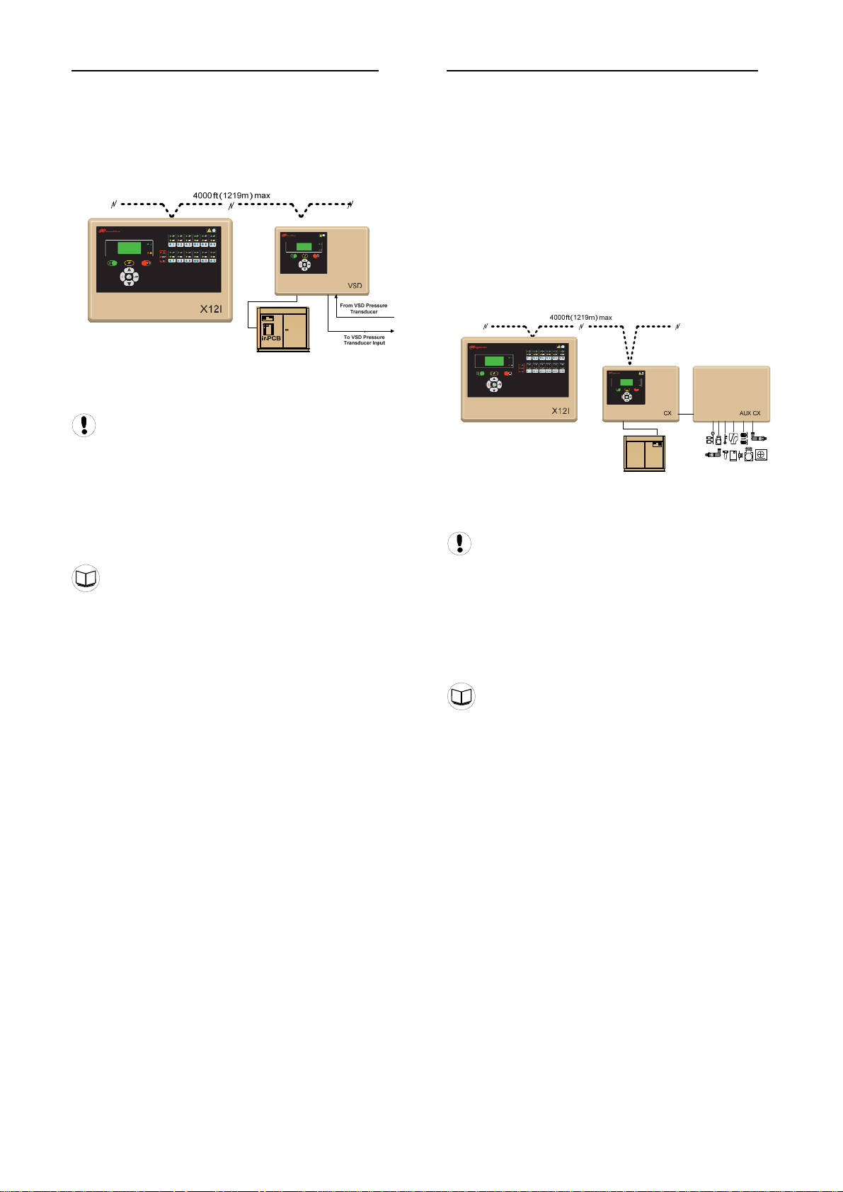
Bolt-On VSD Control Integration: VSD Box (option)
The VSD Box is intended to provide a method of system
integration for a VSD (Variable Speed Drive) air
compressor that is not equipped with any accessible
means of remote connectivity (such as IR- Nirvana). The
VSD Box will provide required functionality to enable
system integration and efficient control using the X12I
utomation system.
a
Remote Compressor Management; CX Box (option)
The CX Box is intended to provide a method of system
integration for non-Ingersoll Rand air compressors that
are not equipped with any accessible means of remote
onnectivity. c
The CX Box provides advanced monitoring and control
unctionality for the following compressor types: f
• Load/Unloa•d
3-Step
• 5-Step
• Poppet Valve
• Modulation Valve
• Spiral Valve
• Variable Speed Inverter Drive
The VSD Box connects to the X12I controller via a two
ire, RS485 network utilizing the ir485 protocol w
Use Belden 9841 or Equivalent In Grounded
Conduit No Greater Than 4000ft (1219m)
Each air compressor in a system, that requires VSD Box
integration, must be equipped with an individual VSD
Box. Multiple VSD Boxes can be connected to the X12I
as long as the number of compressors does not exceed
he maximum number of compressors (12). t
VSD Box Manual
The CX Box connects to the X12I controller via a two
ire, RS485 network utilizing the ir485 protocol w
Use Belden 9841 or Equivalent In Grounded
Conduit No Greater Than 4000ft (1219m)
Each air compressor in a system that requires CX Box
integration must be equipped with an individual CX Box.
Multiple CX Boxes can be connected to the X12I as long
as the number of compressors does not exceed the
aximum number of compressors (12). m
CX Box Manual
7
Page 8
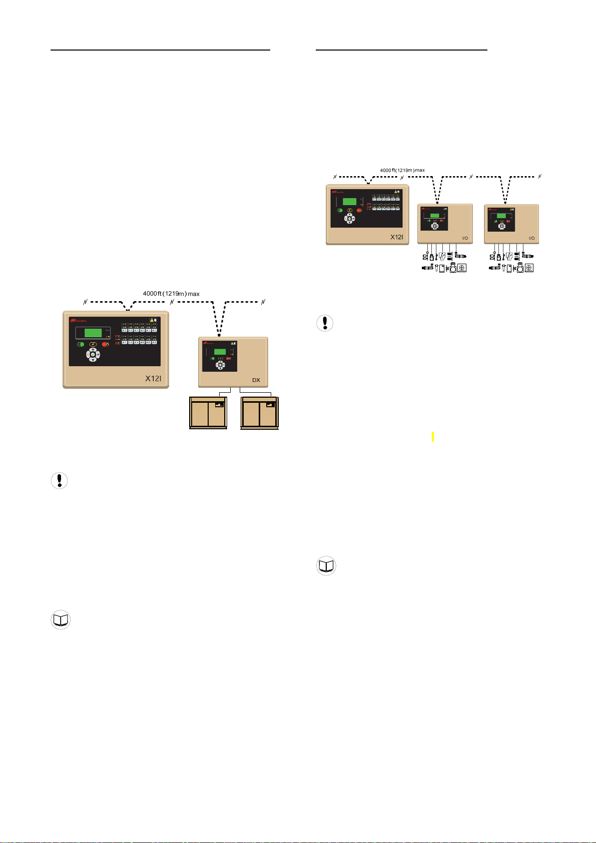
tion) Remote Compressor Management; DX Box (op
The DX Box is designed to allow two fixed speed
online/offline air compressors to be seen as one
ompressor by the X12I. c
This c fun tionality provides the ability to:
a) Group two adjacent air compressors together as
a single coherent unit.
b) Combine two similar capacity compressors
together to form a three-step variable output
group acting as a single coherent variable
output unit.
c) Take advantage of a small or minimal capacity
compressor, grouped together with a medium or
higher capacity compressor, to form a high
capacity, variable output, group acting as a
single variable output ‘top-up’ compressor.
The DX Box also provides optional local pressure sensor
connections. The compressor discharge pressures, local
system pressure and air treatment differential pressures
can be displayed. The monitored local pressure is
available on the system network and can be utilized by
he X12I for advanced pressure related functions. t
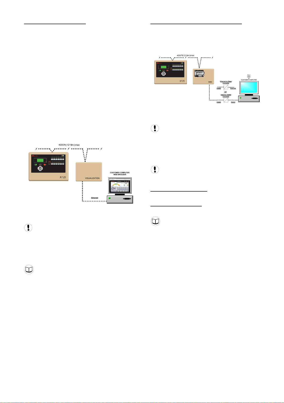
Remote Input & Output: I/O Box (option)
An I/O Box provides additional general purpose I/O
(input/output) for a system enhancing monitoring
apabilities and providing distributed system automation. c
Up to twelve I/O Boxes can be connected to the X12I
ontroller. Each I/O Box features: c
• 8 Digital Inputs
• 5 Analog Inputs
• 6 Relay Outputs
The I/O Box connects to the X12I controller via a two
ire, RS485 network utilizing the ir485 protocol w
The DX Box connects to the X12I controller via a two
ire, RS485 network utilizing the ir485 protocol w
Use Belden 9841 or Equivalent In Grounded
Conduit No Greater Than 4000ft (1219m)
The DX Box provides for two ‘ir-PCB’ connections. The
DX Box can also be used to provide ‘ir-PCB’ connectivity
at a remote location beyond the maximum distance
pecification of direct X12I connection. s
Multiple DX Boxes can be connected to the X12I as long
as the number of compressors does not exceed the
aximum number of compressors (12). m
Use Belden 9841 or Equivalent In Grounded
Conduit No Greater Than 4000ft (1219m)
Digital inputs can be used to monitor switching contact
devices. Each input can be set to act as an Alarm or High
Level Alarm input. Digital inputs can also be used for
metering (for example m
ccumulative count of pulses from a metering device. a
Analog inputs can be used to monitor sensor devices (for
example: pressure differential, temperature, dewpoint,
flow, current, power, and bearing condition). Each input is
equipped with adjustable high or low level detection that
an be used to activate an Alarm or High Level Alarm. c
Relay outputs use ‘Virtual Relay Automation’ technology
and are totally configurable with duel input logic
functions. Relay functions can be assigned utilizing any
status or condition information available on a system
network from any compatible unit connected to the
etwork. n
I/O Box Manual
3
, ft3, kWh) providing an
DX Box Manual
8
Page 9
Visualization: VX Box (Option)
The VX Box provides “visualization” of the X12I
Automation System. The VX Box incorporates hardware
and software to allow monitoring of the X12I Automation
system and equipment in a simple format. To access the
application running in the VX Box, simply connect via a
Web Browser from any PC using an Ethernet connection.
he PC can be local “stand alone” or part of a LAN. T
Once logged into the VX Box, the following items are
vailable to the user: a
System status & control
g System performance reportin
Equipment status monitoring
heduler Equipment maintenance sc
ding tools Graphing & Tren
Reporting tools
monitoring Warning & Alarm
SMS messaging
Email messaging
The VX Box is fully field configurable using standard
creen templates. s
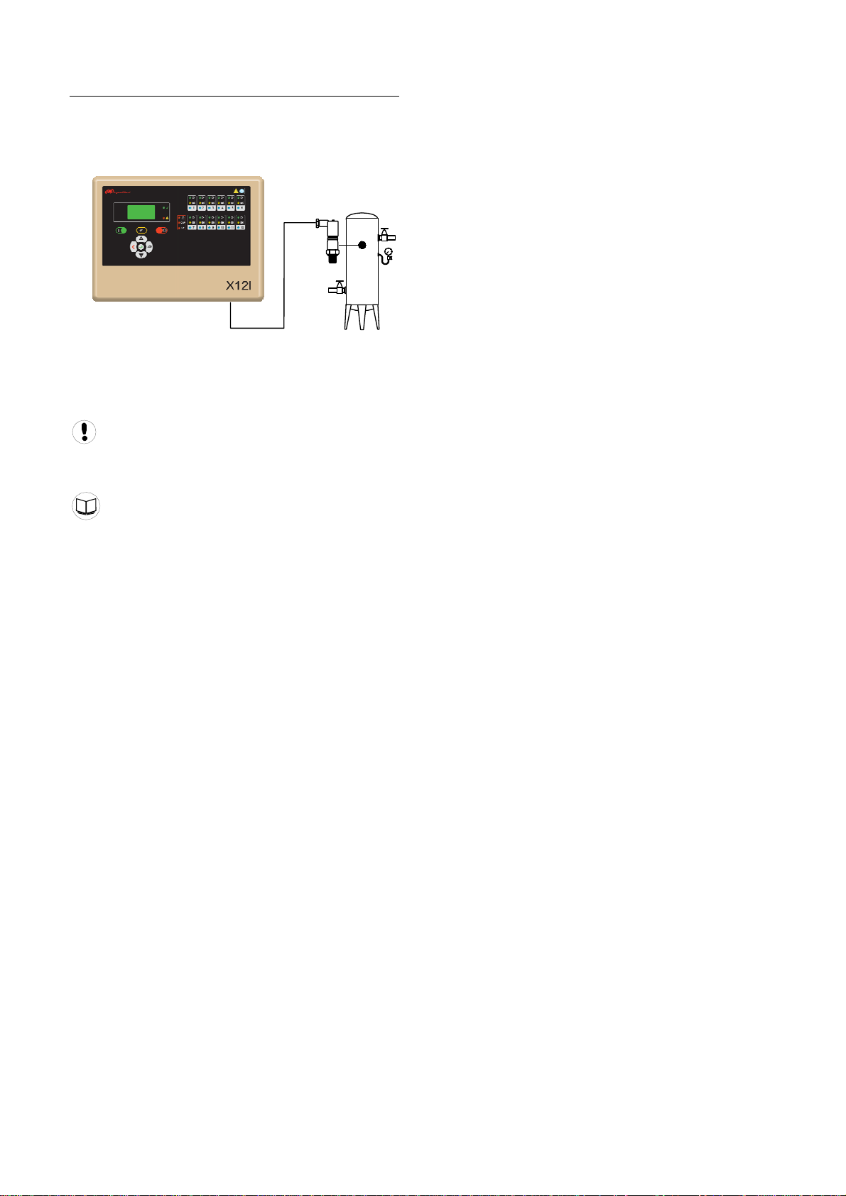
System Modbus Gateway: SMG Box (Option)
The SMG Box is designed to provide a RS485 Modbus
connection to the X12I Automation System. This allows
a customer’s computer, PLC, or DCS to connect to,
monitor, and control the X12I Automation System from a
emote location. r
The SMG Box connects to the X12I controller via a two
ire, RS485 network utilizing the ir485 protocol w
Use Belden 9841 or Equivalent In Grounded
Conduit No Greater Than 4000ft (1219m)
The SMG Box communicates to the customer’s
computer, PLC, DCS via a two wire, RS485 network
tilizing the Modbus protocol. u
The VX Box connects to the X12I controller via a two
ire, RS485 network utilizing the ir485 protocol w
Use Belden 9841 or Equivalent In Grounded
Conduit No Greater Than 4000ft (1219m)
The VX Box connects to the customer’s PC or LAN via
Ethernet, using a RJ45 connector, Cat5e 10/100BaseT
cable.
VX Box Manual
Use Belden 9841 or Equivalent In Grounded
Conduit No Greater Than 4000ft (1219m)
Ethernet to RS485 Converter:
Lantronix XSDRIN-02 Xpress-DR-IAP or equivalent
Serial to RS485 Converter:
&B Electronics 4WSD9OTB or equivient B
SMG Box Manual
9
Page 10
PRESSURE DETECTION AND CONTROL
The X12I utilizes the signal from an electronic pressure
sensor that can be mounted remotely from the X12I in a
suitable location in the compressed air system.
The default setup of the X12I is for operation with a
232psi (16bar) 4-20ma pressure sensor. The X12I can
accept an input from any 4-20mA type pressure sensor
ith a range from 14.5psi (1bar) up to 8700psi (600bar). w
Consult the Pressure Sensor Calibration Procedure
for information regarding the use and setup of the
ressure sensor. p
Pressure Sensor Calibration Procedure
10
Page 11
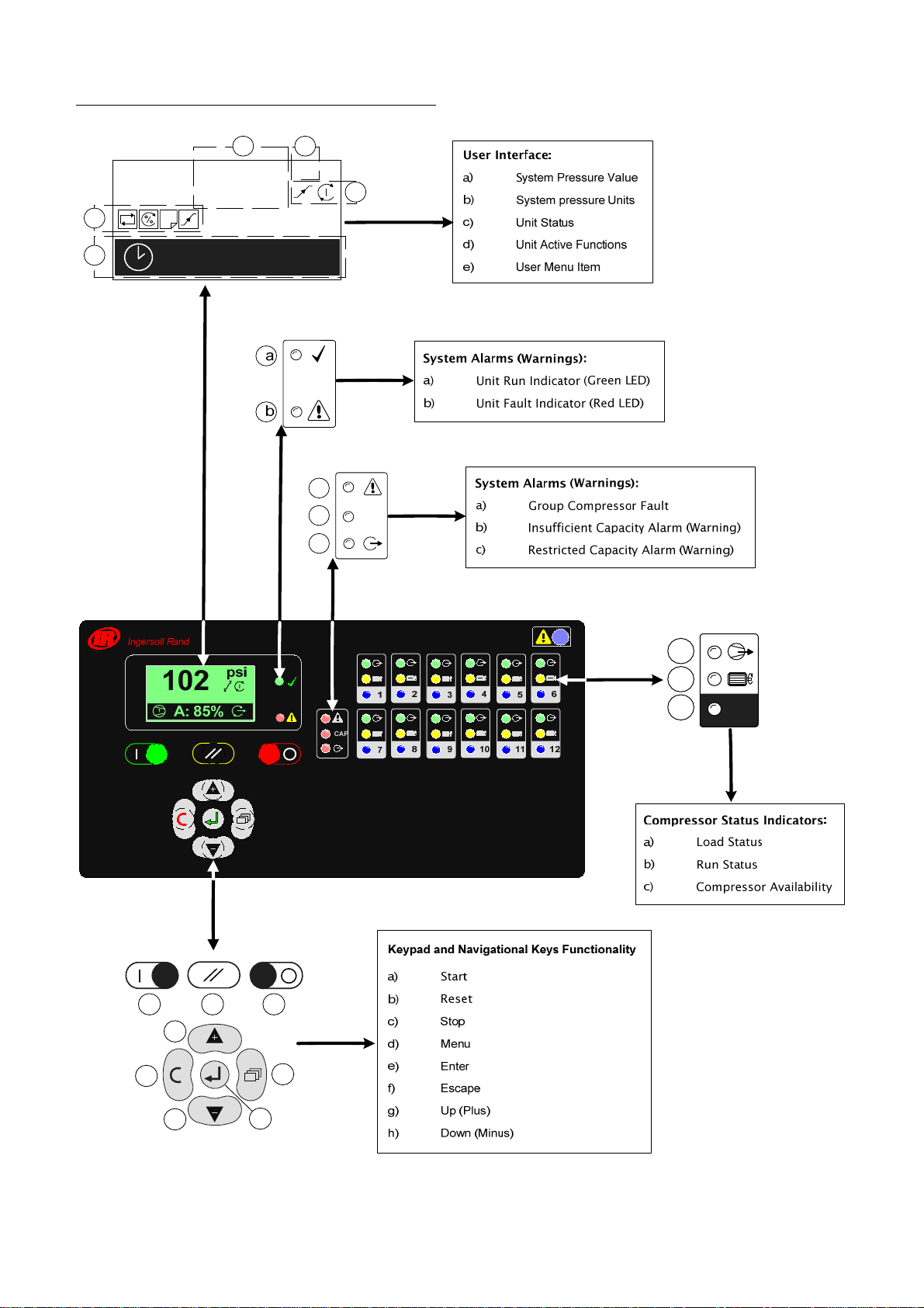
X12I MAIN DISPLAY OVERVIEW
a
b
PSI
102
d
1
c
e
17:30 #1
a
b
CAP
c
a
b
c
a
f
b
g
h
c
d
e
1
11
Page 12
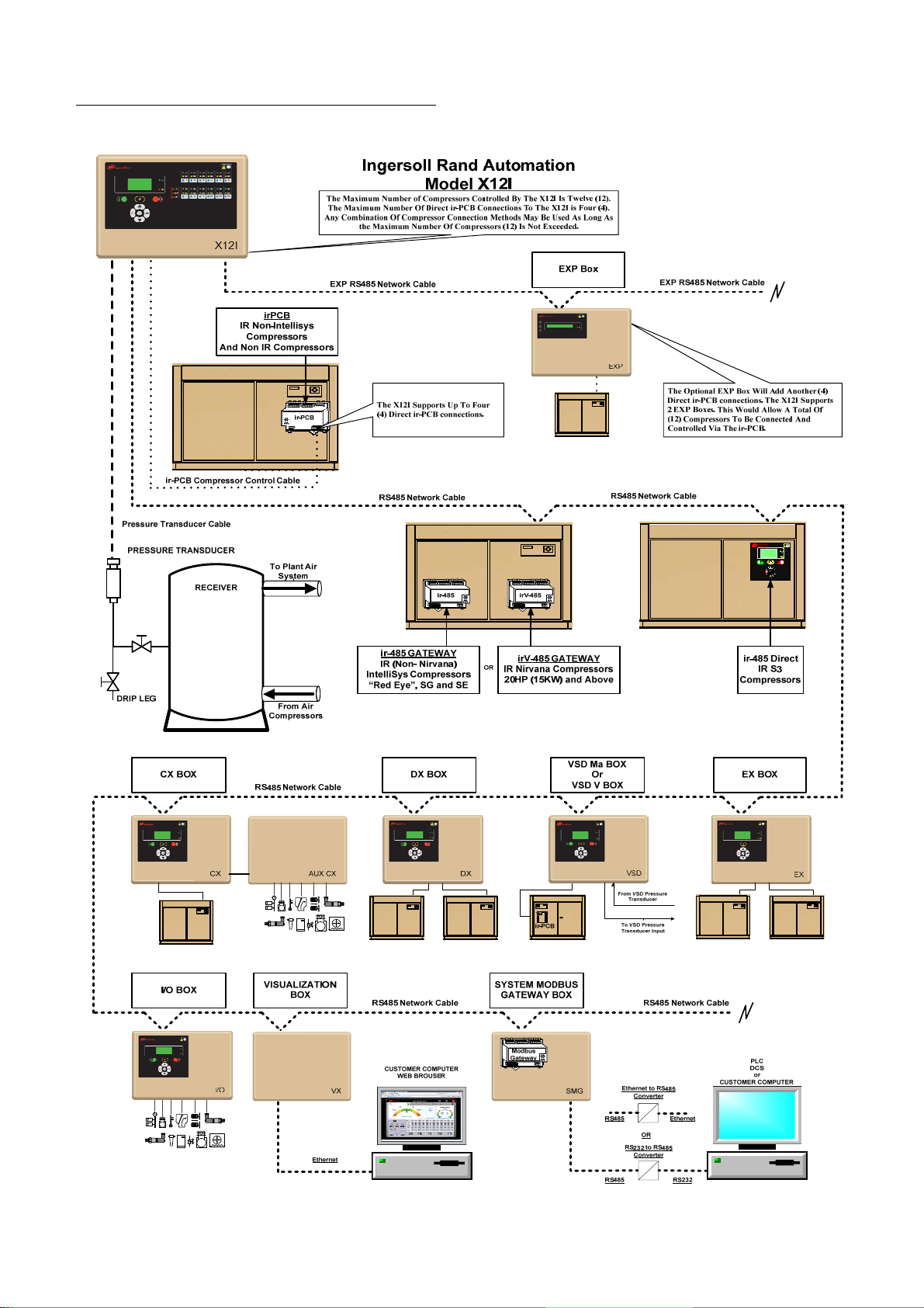
X12I SYSTEM OVERVIEW
12
Page 13
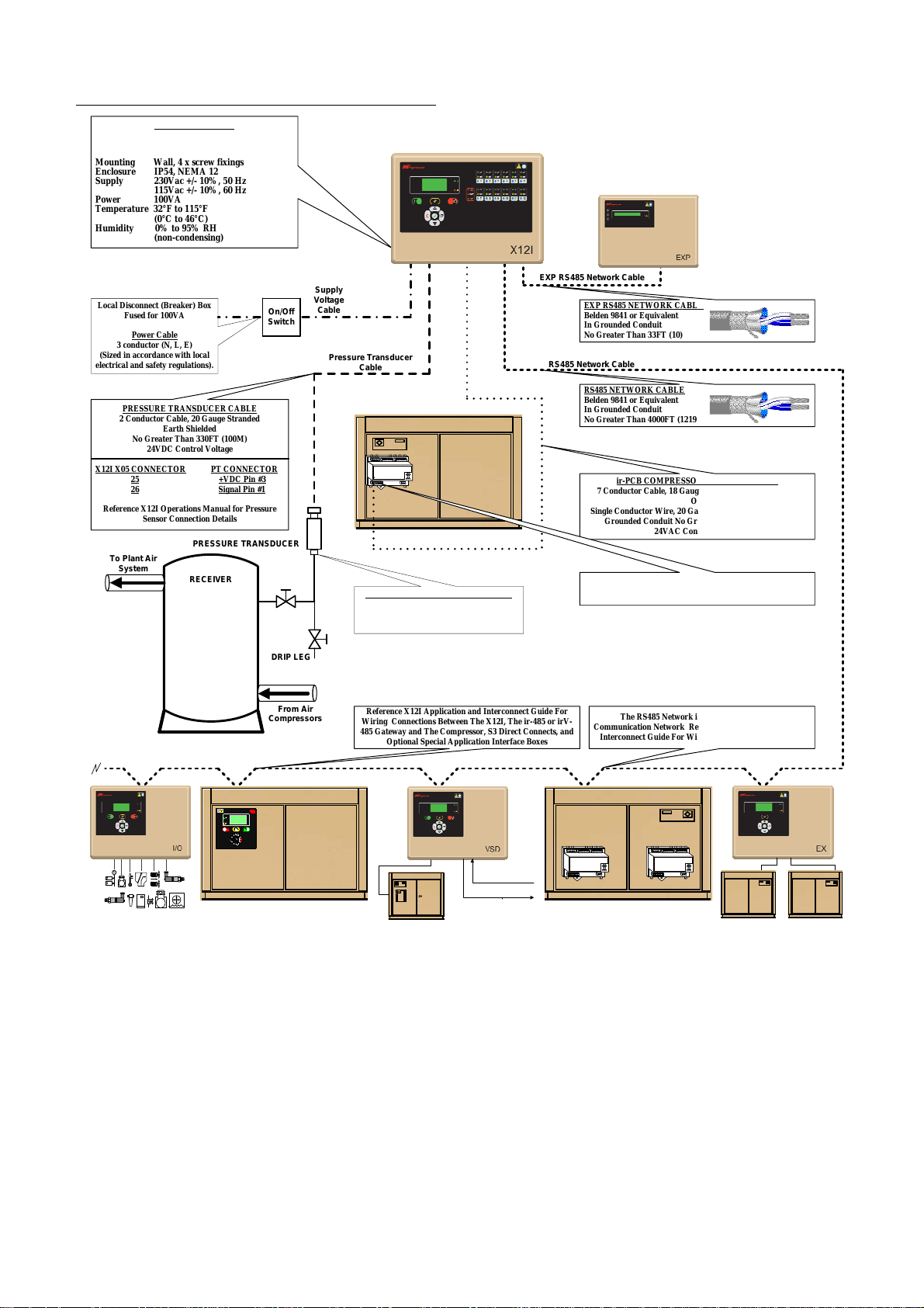
X12I INSTALLATION OVERVIEW
Dimensions 13.4” x 9.45” x 6.0”
Weight 16.5lb (7.5kg)
Mounting Wall, 4 x screw fixings
Enclosure IP54, NEMA 12
Supply 230Vac +/- 10%, 50 Hz
Power 100VA
Temperature 32°F to 115°F
Humidity 0% to 95% RH
Local Disconnect (Breaker) Box
(Sized in accordance with local
electrical and safety regulations).
X12I X05 CONNECTOR
Reference X12I Operations Manual for Pressure
SPECIFICATIONS
340mm x 241mm x 152mm
115Vac +/- 10%, 60 Hz
(0°C to 46°C)
(non-condensing)
Fused for 100VA
Power Cable
3 conductor (N, L, E)
PRESSURE TRANSDUCER CABLE
2 Conductor Cable, 20 Gauge Stranded
Earth Shielded
No Greater Than 330FT (100M)
24VDC Control Voltage
25 +VDC Pin #3
26 Signal Pin #1
Sensor Connection Details
To Plant Air
System
PT CONNECTOR
PRESSURE TRANSDUCER
RECEIVER
On/Off
Switch
Ingersoll Rand Automation
Supply
Voltage
Cable
Pressure Transducer
Cable
PRESSURE TRANSDUCER THREADS
Model X12I
ir-PCB
ir-PCB Compressor Control Cable
BPT G1/4” DIN3852,
Form E, Inox 1, 4305 STainless
Equivalent of ¼” NPT.
EXP RS485 Network Cable
EXP RS485 NETWORK CABLE
Belden 9841 or Equivalent
In Grounded Conduit
No Greater Than 33FT (10)
RS485 Network Cable
RS485 NETWORK CABLE
Belden 9841 or Equivalent
In Grounded Conduit
No Greater Than 4000FT (1219M)
ir-PCB COMPRESSOR CONTROL CABLE
7 Conductor Cable, 18 Gauge, Stranded, Earth Shielded
Single Conductor Wire, 20 Gauge Stranded, Quantity (7) In
Grounded Conduit No Greater Than 330FT (100M)
Reference X12I Application and Interconnect Guide For
Wiring Connections Between The X12I, The ir-PCB, and The
OR
24VAC Control Voltage
Compressor
DRIP LEG
I l
ngersol
Rand
From Air
Compressors
Reference X12I Application and Interconnect Guide For
Wiring Connections Between The X12I, The ir-485 or irV-
485 Gateway and The Compressor, S3 Direct Connects, and
Optional Special Application Interface Boxes
From VSD Pressure
Transducer
ir-PCB
To VSD Pressure
Transducer Input
The RS485 Network is a Serial, Point to Point
Communication Network Refer to the X12I Application and
Interconnect Guide For Wiring Details and Connectivity.
ir-485
irV-485
13
Page 14
SECTION 4 — INSTALLATION
It is recommended that installation and
commissioning be carried out by an authorized and
trained product supplier.
UNIT LOCATION
The X12I can be mounted on a wall using conventional
bolts. The X12I can be located remotely from the
compressors as long as it is within 330 feet (100 meters)
of cable length when connecting compressors directly
with an ir-PCB. When connecting the X12I over the
RS485 communication network the distance is up to
4000 feet (1219 meters) The X12I must be located within
30 feet (100 meters) of the system pressure transducer. 3
POWER SUPPLY
A fused switching isolator must be installed to the main
incoming power supply, external to the X12I. The isolator
must be fitted with a fuse of the correct rating to provide
adequate protection to the power supply cable used (in
ccordance with local electrical and safety regulations). a
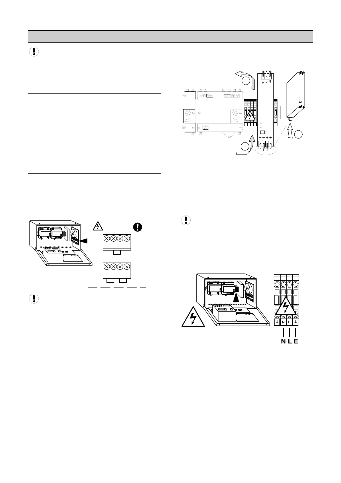
XPM-TAC24
1
X04
X04
23 4
VOLTAGE SELECT
1
23 4
VOLTAGE SELECT
230Vac
115Vac
If it is necessary to adjust the link wires access to the link
terminals can be achieved by temporarily removing the
C Power supply unit (DC) located on the main DIN Rail. D
B
DC
A
C
A) Push the DIN Rail mount button located at the bottom
of the DC Power supply unit. This action can be
achieved by hand; no tooling is required.
B) Remove the DC power supply unit from the DIN Rail
and carefully maneuver to the left. There is no need
to disconnect any wiring.
C) Click the DC power supply unit back in place when
voltage select link adjustment is complete.
The DC power supply unit is mounted in an
inverted orientation on the DIN Rail; this is an
intentional design feature.
Connect the incoming power supply wires to the
power supply terminal blocks located on the main
DIN Rail.
Ensure that the voltage select input is properly
jumpered for the incoming power. Default voltage
onfiguration is 230Vac. c
14
Page 15
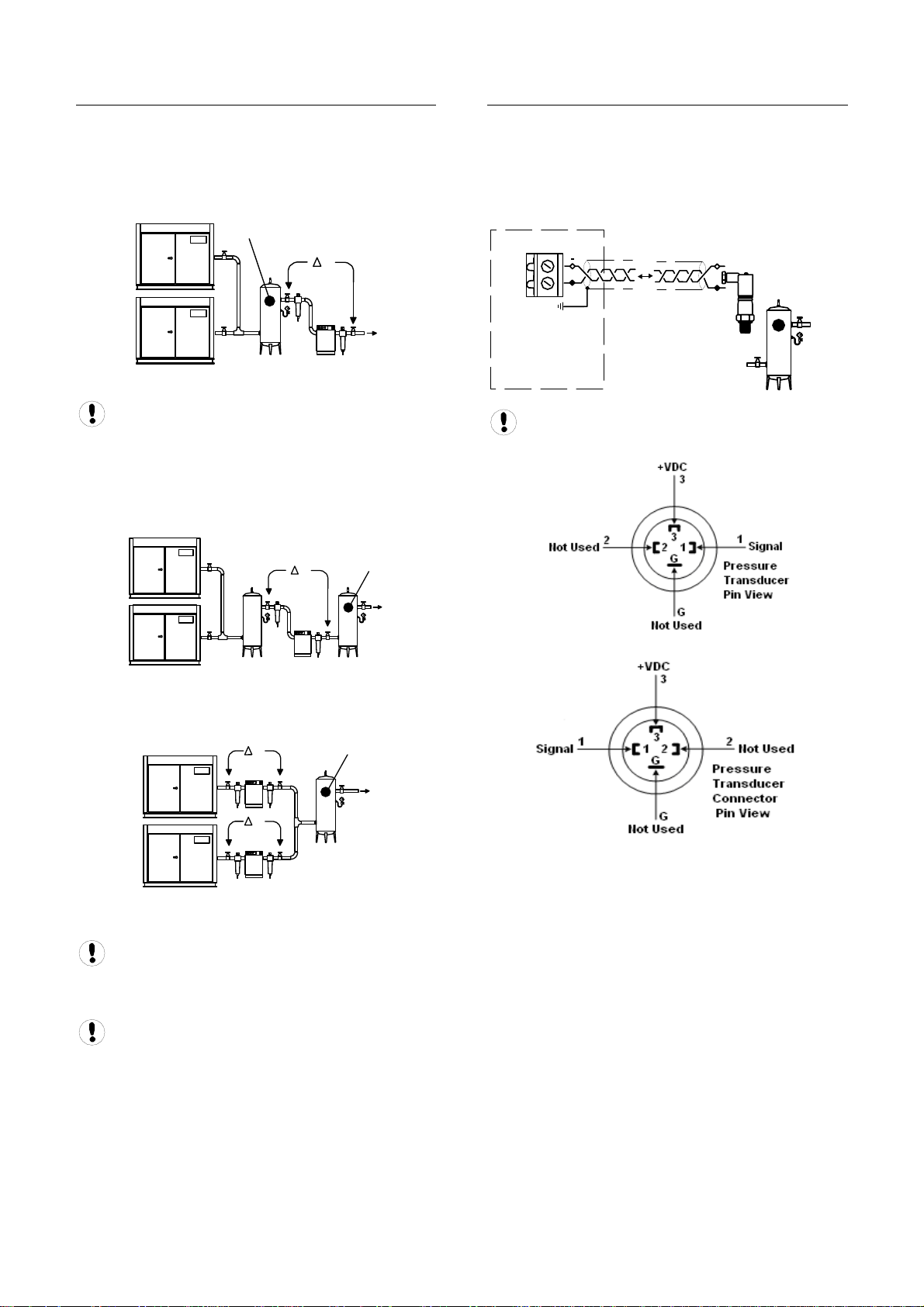
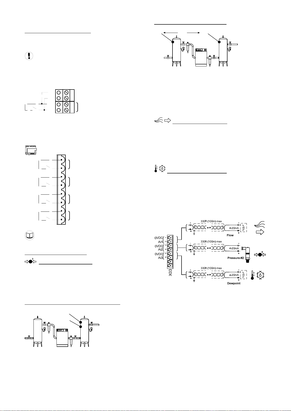
PRESSURE SENSOR LOCATION
The system pressure sensor (P) must be located where it
will see the air pressure that is common to all of the
ompressors. c
SUPPLY (WET) Side Pressure Control
P
1
P
2
Pressure Sensor Located Before Cleanup Equipment
Dry side pressure will be lower than the system
pressure due to pressure differential losses across air
treatment equipment. The nominal system pressure will
reduce as the air treatment differential pressure
ncreases. i
DEMAND (DRY) Side Pressure Control
PRESSURE SENSOR CONNECTION
The pressure sensor must be connected to terminal X05
of the X12I Terminal PCB using a shielded (earth
screened), two-conductor (2 core), 20 gauge (0.5mm2
CSA minimum), cable no greater than 330ft (100m) in
ngth. le
X05
26
25
+
Wire polarity is important.
-
+
4-20mA
1
P
P
2
Pressure Sensor Located After Shared Cleanup
Equipment
P
P
1
P
2
Pressure Sensor Located After Individual Cleanup
Equipment
Ensure each compressor is equipped with
independent excess pressure shutdown. An increase in
pressure differential across air treatment equipment can
result in excess compressor discharge pressure.
Pressure Sensor Wiring and Location
The pressure transducer threads are BPT G1/4”
DIN3852, Form E, Inox 1, 4305 stainless. It is the
quivalent of ¼” NPT. e
Regular routine monitoring of pressure differential
across air treatment equipment is recommended.
15
Page 16
IR-485 AND IRV-485 GATEWAY
MODULE
The ir-485 and irV-485 Gateways are designed to
interface the Intellisys Controller on the Ingersoll Rand
Compressors and the Nirvana compressors, 20 HP
(15KW) and above, with the X12I via the RS485 Network
utilizing the ir485 protocol. The ir-485 and irV-485
Gateways are DIN Rail mounted and can be located
within the compressor control gear enclosure or remotely
within a separately enclosure.
irV-485
ir-485 Gateway irV-485 Gateway
The cable used between the X12I and the ir-485 and irV485 Gateways is Belden 9841 (or equivalent). It should
be run in grounded conduit and should not be greater
than 4000 feet (1219 meters) in length.
The cable used between the ir-485 Gateway and irV-485
Gateways and the Intellisys Controller is included with
the Installation Kit
Consult the X12I Interconnect and Application
Guide and the ir-485 or irV-485 Gateway Manual prior to
the installation of the X12I and the Compressor Gateway
to the air compressor.
IR485 COMMUNICATION PROTOCOL
ir485 is a unique communication protocol designed
specifically for Compressor and Air System control. ir485
is a Multi-Master vs. a Master–Slave protocol that
enables faster, more effective control of network
components. ir485 also features distributed control
capabilities and has inherent resistance to
ommunication faults due to noise c
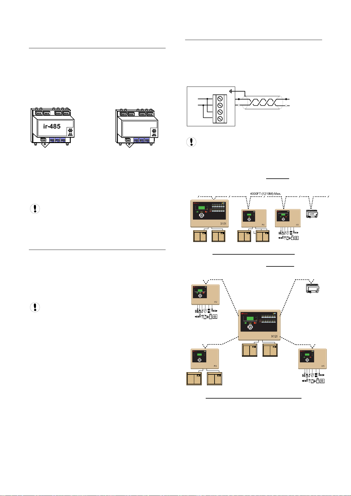
RS485 NETWORK
The X12I is equipped with an RS485 network
communications capability using the ir485 protocol. This
facility can be used for remote connectivity to optional
networked units and modules with ir485 communications
capabilities or compressor controllers equipped with the
485 capability. ir
X06
L2
L1
The RS485 Network is a Serial, Point to Point
Communication Network. Refer to the X12I Application
and Interconnect Guide For Wiring Details and
onnectivity. C
The following example details the “correct”
iring the RS485 Network w
The following example details the “incorrect” method of
iring the RS485 Network w
30
29
28
27
RS485
method of
Correct RS485 Network Example
L2
L1
ir-485
Follow RS485 Network installation
recommendations
Incorrect RS485 Network Example
16
Page 17
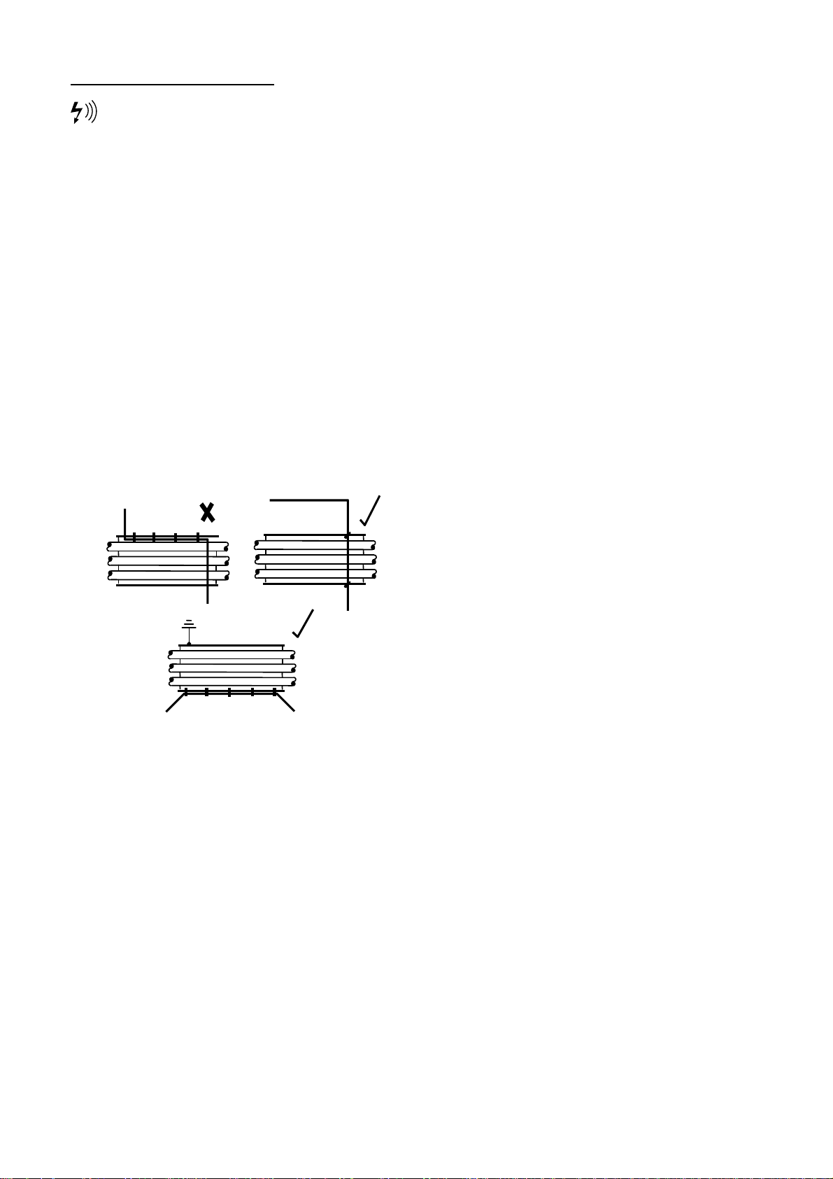
S485 Installation ConsiderationsR
RS485 data communications and other low voltage
signals can be subject to electrical interference. This
potential can result in intermittent malfunction or anomaly
that is difficult to diagnose. To avoid this possibility
always use earth shielded cables, securely bonded to a
known good earth at one end. In addition, give careful
onsideration to cable routing during installation. c
a) Never route an RS485 data communications or low
voltage signal cable alongside a high voltage or 3-phase
power supply cable. If it is necessary to cross the path of
power supply cable(s), always cross at a right angle. a
b) If it is necessary to follow the route of power supply
cables for a short distance (for example: from a
compressor X12I to a wall along a suspended cable tray)
attach the RS485 or signal cable on the outside of an
earthed cable tray such that the cable tray forms an
earthed electrical interference shield.
c) Where possible, never route an RS485 or signal cable
near to equipment or devices that may be a source of
electrical interference (for example: 3-phase power
supply transformer, high voltage switchgear unit,
frequency inverter drive module, radio communications
ntenna). a
17
Page 18
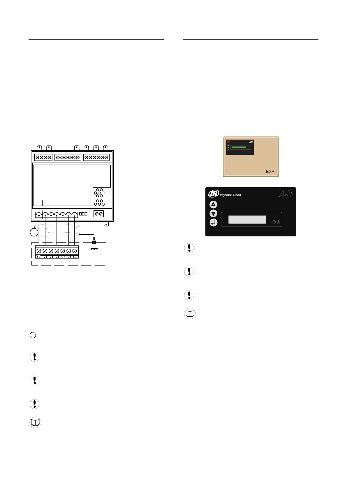
COMPRESSOR INTERFACE IR-PCB
The ‘ir-PCB’ is designed to interface a compressor with
the X12I using a 6-core (or 7-core for IRV-PCB
operation), earth shielded, cable no greater than 330ft
100 meters) in length. (
Each compressor in the system must be assigned a
unique identification number from 1 up to the number of
compressors in the system. The identification number
should be clearly indicated on each compressor for
perational reference. o
For each compressor connected to the X12I utilizing an
‘ir-PCB,’ the signal wires must be connected to the X12I
terminals dedicated for the assigned compressor
eference number. r
C01 C02 C04
i-PCB
C03
V
24613 5
#1
C05
IR-PCB EXP BOX (OPTION)
As standard the X12I has four direct connect ‘ir-PCB’
terminal connections. This capability can be extended
with the use of optional ir-PCB EXP Box(s). Each box
adds another four direct connect ‘ir-PCB’ terminals. Up to
two ir-PCB EXP Boxes can be connected to the X12I to
provide a maximum of 12 direct connect ‘ir-PCB’
erminals. t
The ir-PCB EXP Box is wall mounting and must be
located adjacent to the X12I unit. The distance between
the X12I and the ir-PCB EXP Box is no greater than 33ft
10m). (
LED 1 LED 2
V
X01
246135
V1
The ‘ir-PCB’ is a DIN rail mountable module designed to
be installed within the compressor control or switchgear
rea. a
Each air compressor must be equipped with a
load/unload regulation system and, if not regulated with a
single electro-mechanical pressure switch, have a facility
for a remote load/unload control with the ability to accept
volt-free switching contact input for remote load/unload. a
V
For variable speed compressor(s) equipped with a
‘variable/fixed’ digital input function; Install a 7-core cable
from the ‘ir-PCB’ to the X12I.
Consult the air compressor manual or your air
compressor supplier/specialist for details before installing
the X12I.
Consult the X-Series Interconnect and Application
Guide prior to the installation of the X12I and the ir-PCB
to the air compressor.
C: 5 - 8
Consult the air compressor manual or your air
compressor supplier/specialist for details before installing
the X12I.
Consult the X12I Interconnect and Application
Guide prior to the installation of the X12I and the ir-PCB
to the air compressor.
Consult the EXP Box Instruction Manual for
information regarding the use of the EXP Box.
EXP Box Instruction Manual
Consult the ir-PCB Instruction Manual for
information regarding the use of the ir-PCB.
ir-PCB Instruction Manual
18
Page 19
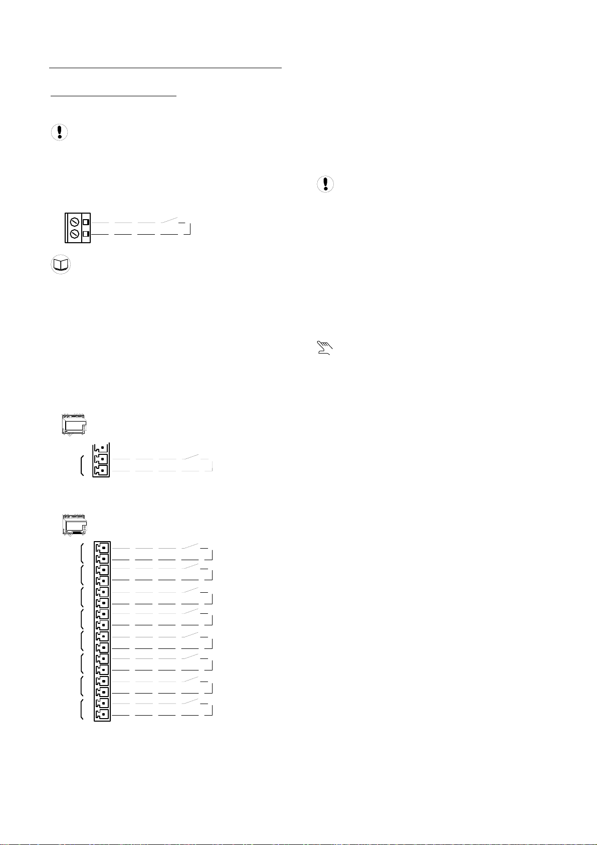
ON BOARD I/O OPTIONS
DIGITAL INPUTS (OPTIONS)
T he X12I is equipped with ten auxiliary inputs.
Each input is designed to detect a remote ‘volt-free’
switching contact (rated for a minimum 24VDC @ 10mA)
ith a cable length of 330ft (100m) maximum. w
D i1: Digital Input 1, Menu Configurable
X07
32
31
Menu Items – S02:D1
he functions of Di2 to Di10 are fixed. T
ange Di2: Force Sequence Ch
Di3: Remote Start/Stop
Di4: Standby Override
Di5: Table 1 Override
Di6: Table 2 Override
Di7: Table 3 Override
Di8: Table 4 Override
Di9: Table 5 Override
i10: Table 6 Override D
XPM-Ai4
X03
Di1
Di2: Force Sequence Change
Initiates an immediate change/review of the compressor
sequence assignment. The input must be activated for a
minimum of two second. Routine scheduled sequence
change events are not disrupted and will still occur as
ormal. n
Di3: Remote Start/Stop
A start command is generated when the input changes
state from open to closed. The input must remain closed
while running. A stop command is generated when the
put changes state from closed to open. in
Local and Communications Start and Stop remain
active. If the Stop button is pressed while this input is
eld closed, the unit will stop. h
Di4: Standby Override
All compressors are unloaded and continuously held
offloaded. Any active ‘Table’ override input has priority
ver the standby override input. o
Di5 to Di10: Table 1 to 6 Override
The X12I will select the applicable ‘Table’ when a table
input is activated. The X12I will return to normal table
selection, in accordance with pressure schedule or menu
etting, when no table input is activated. s
When a table override input is activated the display
will show a manual table override symbol adjacent to the
able’ symbol. ‘t
If more than one table override input is activated at the
same time the X12I will give priority to the lowest table
number. For example: If table 2 and 3 override inputs are
activated at the same time the X12I will use table 2.
0VDC
Ai4
7
8
Di2
XPM-Di8R4
X03
1
Di1
2
3
Di2
4
5
Di3
6
7
Di4
8
9
Di5
10
11
Di6
12
13
Di7
14
15
Di8
16
Di3
Di4
Di5
Di6
Di7
Di8
Di9
Di10
19
Page 20
DIGITAL OUTPUTS (OPTIONS)
The X12I is equipped with five remote relay contact
utput. o
Remote output relay contacts are rated for 240V
‘CE’ / 115V ‘UL’ @ 4A maximum.
1: Relay Output 1, Menu Configurable R
X08
36
35
34
33
R1
R2: Relay Output 2, Menu Configurable
R3: Relay Output 3, Menu Configurable
R4: Relay Output 4, Menu Configurable
5: Relay Output 5, Menu Configurable R
XPM-Di8R4
X03
1
R1
2
3
R2
4
5
R3
6
7
R4
8
R2
R3
R4
R5
P2+>DP: Pressure Differential Mode
P1P2 DP
The second pressure sensor can be used to monitor
pressure downstream, or upstream, of air treatment
equipment. The pressure differential (DP) between the
primary control pressure sensor (P1) and the second
pressure sensor (P2) can be displayed on the screen. A
pressure differential Alarm (Warning) level can also be
set to indicate when differential pressure exceeds the set
mit. li
Airflow Sensor Monitoring
The X12I is equipped with a 4-20mA input dedicated for
optional airflow sensor monitoring. Any airflow sensor,
that is equipped with a ‘loop powered’ 4-20mA output,
can be connected to the X12I. The airflow sensor value
can be displayed on the X12I screen and is available on
emote communications. r
Dewpoint Sensor Monitoring
The X12I is equipped with a 4-20mA input dedicated for
optional dewpoint sensor monitoring. Any dewpoint
sensor, that is equipped with a ‘loop powered’ 4-20mA
output, can be connected to the X12I. The dewpoint
sensor value can be displayed on the X12I screen and is
available on remote communications.
Virtual Relay Automation – R1 to R5
ANALOG INPUTS (OPTIONS)
Second Pressure Sensor:
The X12I is equipped with a 4-20mA input dedicated for
n optional second pressure sensor. a
The second pressure sensor (P2) can be utilized for one
f two available functions: o
1<>P2: Redundant Pressure Transducer ModeP
P1
P2
If the primary control pressure sensor (P1) fails the
management unit will automatically switch to the ‘backup’
ressure sensor (P2). p
20
Page 21
SECTION 5 — CONTROL FEATURES AND FUNCTIONS
PRESSURE CONTROL
Pressure control is achieved by maintaining the system
pressure within an acceptable range, or pressure band,
which is defined and programmed by the user. Pressure
will rise in the band when system demand is less than
the loaded compressor’s output. Pressure will fall in the
band when system demand is greater than the loaded
ompressor’s output. c
Simply stated, pressure control is achieved by unloading
and loading compressors to closely match compressor
output with system demand within a specified pressure
and defined by PL and PH. See Figure 1. b
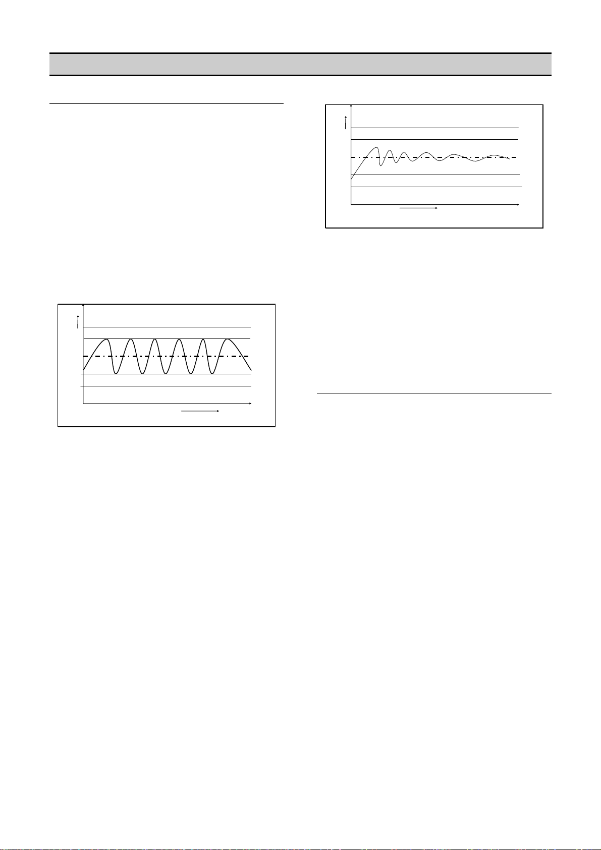
Variable speed compressors also operate within the
pressure band and actively match compressor output
with system demand by speeding up and slowing down
around a target pressure defined by the exact midpoint of
the pressure band defined by PT. See Figure 2.
a
b
PH
PT
PL
PH
PT
PL
Figure 2 — Typical VSD Pressure Control vs. Time
The variable speed compressors in the system will run on
their target pressure and smooth out the variations in
system pressure. This assumes that system demand
does not vary more than the capacity of the variable
peed compressor. s
A variable speed compressor will be included in the
load/unload sequence and be controlled exactly as a
fixed speed machine with the exception of speed control
to maintain target pressure.
ANTI-CYCLING CONTROL
Figure 1 — Typical System Pressure vs. Time
As pressure rises to point “a”, the compressor will unload
based on the sequencing algorithm. System pressure is
then allowed to decrease due to the drop in supply until
point “b” is reached. Once point “b” is reached, the X12I
will load the next compressor in the sequence to match
the air demand. This cycle will repeat as long as the X12I
is able to keep the system air pressure between PH and
PL.
The most efficient way to utilize most air compressors is
either fully loaded or off, with the exception of variable
speed compressors which can operate efficiently at
reduced loading. Compressor cycling (start-load-unloadstop, etc.) is essential to maintain pressure control.
Excessive cycling, however, can result in poor
ompressor efficiency as well as increased maintenance.
c
Anti-cycling control is incorporated to help ensure that
only the compressors that are actually required are
started and operating while all others are kept off. Anticycling control includes a pressure tolerance range or
band, defined by the user, which is outside of the primary
pressure band. Inside the tolerance band, an active
control algorithm continually analyzes pressure dynamics
to determine the last possible second to add or cycle
another compressor into the system. This control is
further enhanced by the ability to fine tune the tolerance
and settings and algorithm processing time (Damping). b
21
Page 22
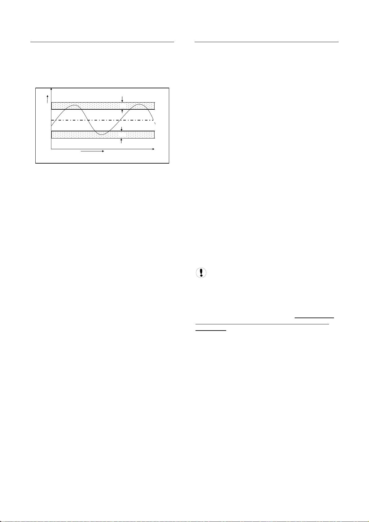
TOLERANCE
Tolerance is a user adjustable setting that determines
how far above the PH Setpoint and below the PL
Setpoint system pressure will be allowed to stray.
Tolerance keeps the X12I from overcompensating in the
event of a temporary significant increase or decrease in
system demand.
TO
TO
Figure 3 — Tolerance in Relation to PH and PL
Tolerance (TO) is expressed as a pressure defining the
width of the band above PH and below PL in which
energy efficient control will be in effect.
When system pressure is in the tolerance band, the X12I
will continuously calculate the moment at which
compressors will be loaded or unloaded based on the
rate of change of system pressure. When the system
pressure strays outside of the tolerance band, the X12I
will abandon energy efficiency and begin to protect the
system air pressure by loading or unloading the
ompressors. Loading will be delay controlled. c
When the compressed air system storage is relatively
small compared to the system demand, and fluctuations
are large and quick, the tolerance band setting should be
increased to maintain energy efficient operation and
avoid a situation in which multiple compressors are
oaded just to be unloaded moments later. l
When the compressed air system is relatively large
compared to system demand and fluctuations are smaller
and slower, the tolerance band can be reduced to
improve pressure control and maintain energy efficient
operation.
The factory default setting for tolerance is 3.0 PSI
0.2Bar). This setting is user adjustable. (
PH + TO
PH
PT
PL
PL - TO
DAMPING
Any time the pressure is within the Tolerance band the
Anti-Cycling algorithm is active, sampling the rate of
pressure change and calculating when to load or unload
the next compressor. The damping (DA) setting is a user
adjustable Setpoint that determines how quickly the
controller samples and recalculates, effectively speeding
p or slowing down the reaction time. u
The X12I’s factory default DA setting of “1” is adequate
for the majority of compressed air systems but may need
to be adjusted in the following circumstances involving
aggressive and disproportionate system pressure
hanges: c
• Inadequate air storage
• High pressure differential across the air
treatment equipment
• Incorrectly sized piping
• Slow or delayed compressor response
In these circumstances, the X12I may overreact and
attempt to load additional compressors that may not be
necessary if the system was given time to allow the
system pressure to stabilize after the initial compressor is
given time to load. If the tolerance has already been
increased and the X12I is still overreacting, then
creasing the damping factor is the next step. in
Damping is adjustable and is scaled from 0.1 to 10 with a
factory default of 1. A factor of 0.1 is a reaction time 10
times faster than the default and a factor of 10 is a
eaction time 10 times slower than the default. r
There are many variables that go into
determining the stability and control of the system
pressure, only some of which are able to be
controlled by the X12I. System storage, air
compressor capacity, and air demand all need to be
analyzed by experienced professionals to determine
the best installation for your system. Tolerance (TO)
and damping (DA) can be used for minor tuning of
the system.
22
Page 23
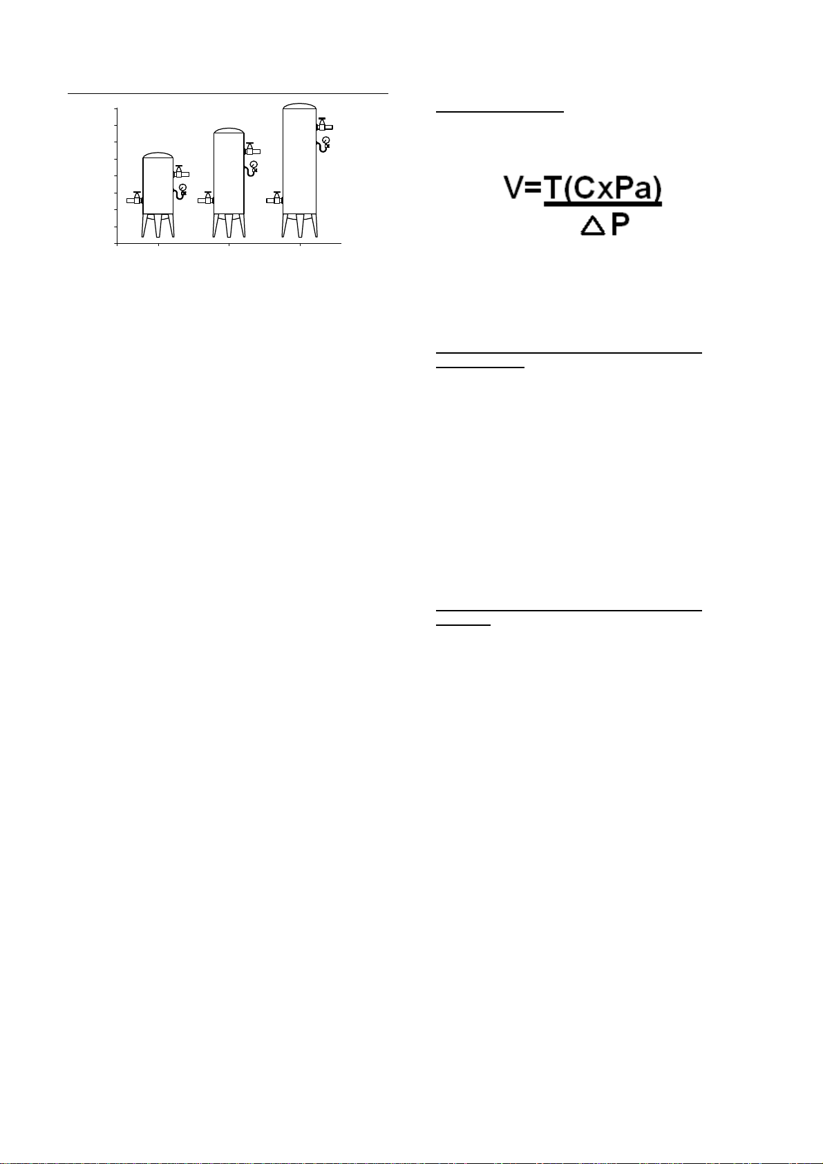
SYSTEM VOLUME
torage Calculations:S
The following formula determines the recommended
inimum storage volume for a compressed air system: m
-
+
Assorted Receiver Tanks
System volume defines how fast system pressure will
rise or fall in reaction to either increased/decreased
demand or increased/decreased supply. The larger the
system volume, the slower the pressure changes in
relation to increased/decreased demand or supply.
Adequate system volume enables effective pressure
control and avoids system over-pressurization in
response to abrupt pressure fluctuations. Adequate
system volume is created by correctly sizing and utilizing
ir receivers. a
The most accurate way to determine the size of air
receivers or the additional volume required would be to
measure the size and duration of the largest demand
event that occurs in the system, then size the volume
large enough to ride through the event with an
acceptable decrease in system pressure. Sizing the
volume for the worst event will ensure system stability
and effective control over all other normal operating
onditions. c
If measurement is not available, then estimating the
largest event is a reasonable alternative. For example,
assume that the largest demand event could be equal to
the loss of the largest operating air compressor. System
volume would be sized to allow time for a back-up
compressor to be started and loaded with an acceptable
decrease in pressure.
V — “Volume of Required Storage” (Gal, Ft , m , L)
T — “Time to Start Back-up Compressor” (Minutes)
3 3
M, m
3
Pa — “Atmospheric pressure” (PSIa, BAR)
P — “Allowable Pressure Drop” (PSI, BAR) ∆
3
Ft
and US Gal.
(4) - 100 Hp Compressors at 450 CFM (12.7 m
Required Storage Volume in Example 1: Find
3
) each
15 seconds to start and load a compressor.
5PSIG pressure drop. is the maximum allowable
nds (.25 minute) T=15 Seco
C=450 ft
3
Pa = 14.5 PSI
Delta P = 5 PSI
.5)]/5 V = [.25 x (450 x 14
525)/5 V = (.25 x 6
V = 1631/5
V = 326 Ft
1 ft = 7.48 Gal
3
3
3
x 7.48 Gal= 326 Ft
Gal = 2440
: Find Required Storage Volume in Example 2
3
) each 4) - 100 Hp Compressors at 450 CFM (12.7 m
m
(
3
and L.
15 seconds to start and load a compressor.
0.34 B essure drop. AR is the maximum allowable pr
ds (.25 minute) T=15 Secon
C=12.7 m3
Pa = 1BAR
Delta P = .34 BAR
]/.34 V = [.25 x (12.7 x 1)
2.7)/.34 V = (.25 x 1
V = 3.2/.34
V = 9.33m
1m = 1000 L
3
3
3
x 1000 L= 9.33
m
L = 933
/min) C — “Lost Capacity of Compressed Air” (CF
23
Page 24
SEQUENCE CONTROL STRATEGIES
The X12I provides three basic sequence control
strategies or modes. Each sequence control strategy
onsists of two sub strategies: c
1) The compressor ‘Rotation’ strategy
2) The compressor load ‘Control’ strategy
The ‘Rotation’ strategy defines how the compressors
are re-arranged, or re-ordered, in to a new sequence at
each routine ‘Rotation’ event. Rotation events are
triggered by a cyclic interval time, a set time of day each
ay, or a set time of day once a week. d
The compressor load ‘Control’ strategy defines how
the compressors are utilized in response to variations in
ystem pressure. s
ompressor Sequence Arrangements: C
Each compressor in a system is initially assigned to the
X12I with a fixed and unchanging number reference, 1 to
2. 1
The ‘duty’ that a compressor is assigned in any set
‘Rotation’ sequence arrangement is defined by a letter, A
o L. t
For example:
A = the ‘Duty’ compressor, the first to be utilized.
d. B = The ‘Standby’ compressor, the second to be utilize
C = The ‘Second Standby’ compressor, the third to be
utilized.
D = The ‘Third Standby’ compressor, the forth to be
tilized. u
Compressor ‘duty’ assignments are reviewed, and rearranged as appropriate in accordance with the selected
rotation strategy, at each rotation event.
STANDARD CONTROL FEATURES AND
FUNCTIONALITY
The standard (default) configuration of the X12I provides
ENER (Energy Control) sequence control strategy,
Priority Settings, Table Selection, Pressure Schedule,
nd Pre-fill operation. a
ENER: ENERGY CONTROL MODE
he primary function of Energy Control mode is to: T
1/ Dynamically match compressed air supply with
compressed air demand.
2/ Utilize the most energy efficient set/combination of air
ompressors to achieve 1/. c
Energy Control mode is designed to manage systems
that include compressors of different capacities and
different air compressor types (fixed speed, variable
speed and variable capacity) in any combination or
onfiguration. c
Energy Control Mode Control and Rotation:
Compressor control and utilization is dynamically
automated with adaptive control logic and therefore does
not follow pre-determined schedules, rotation
configurations or time intervals. Energy Control mode
can, however be operator influenced by the Priority
unctionality which is discussed later in this manual. f
Energy Control mode is enabled by the ability of the X12I
to process individual compressor capacity, variable
capacity capabilities, and changes in system pressure to
dynamically implement and continuously review ‘best fit’
onfigurations as demand variations occur. c
100%
80%
2
40%
20%
0%
0%
1: Demand
1
100%
2: Supply
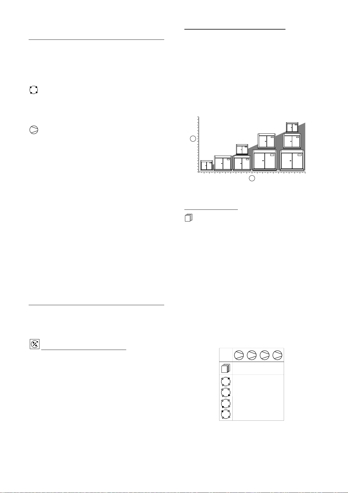
PRIORITY SETTINGS
The sequence assignment pattern can be modified
y using the priority settings. b
Priority settings can be used to modify the rotation
sequence assignments. Compressors can be assigned a
priority of 1 to 12, where 1 is the highest priority. Any
compressor can be assigned any priority and any number
of compressors can share the same priority.
Priorities allow you to set up rotation groups. All
compressors that have the same priority number will
rotate inside their own group. The group with the highest
riority will always be in the front of the sequence. p
For example, in a four compressor system including one
variable speed compressor in the compressor 1 position
you may want the variable speed compressor to always
be in the Lead position. By assigning compressor 1 a
priority of 1 and the other three compressors a priority of
2, the variable speed compressor will always remain at
the front of the sequence:
1 2 3 4
1222
#1
ABCD
#2
ACDB
#3
ADBC
#4
ABCD
Compressor 1 has priority 1, all other compressors
have priority 2
24
Page 25
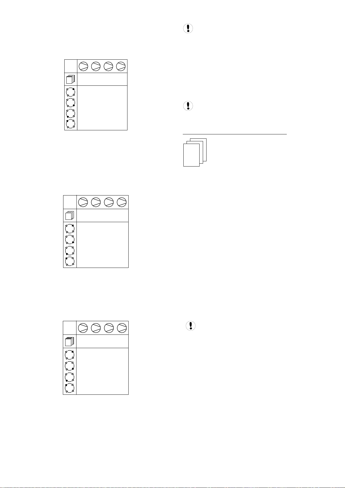
In another example, there is a four compressor system
that includes a compressor in the compressor 4 spot that
is used only as an emergency backup compressor. To
accomplish this, simply assign compressor 4 a lower
priority than any other compressor in the system:
1 2 3 4
1112
#1
ABCD
#2
BCAD
#3
CABD
#4
ABCD
Compressor 4 has priority 2, all other
compressors have priority 1
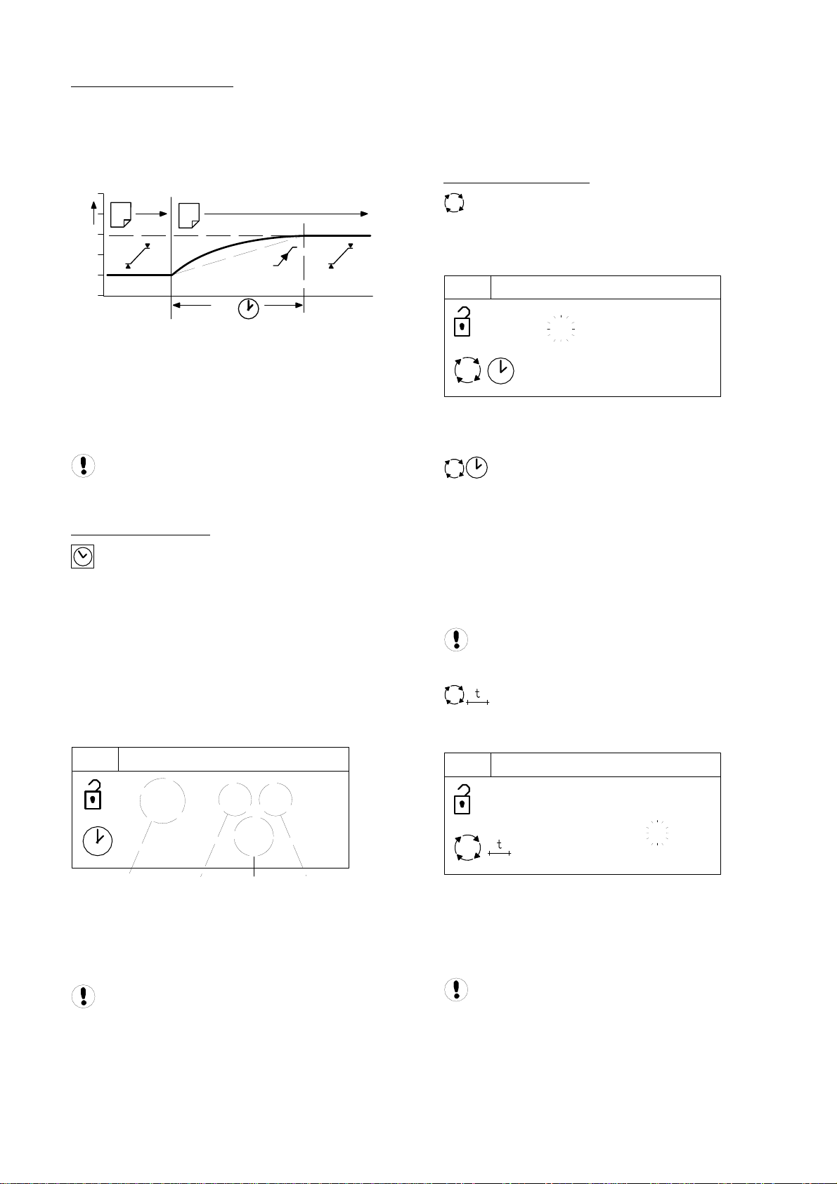
In a third example, there is a four compressor system
that includes a variable speed compressor designated
compressor 1 and a fixed speed compressor that is an
emergency backup assigned as compressor 4. To ensure
that compressor 1 is always at the front of the sequence
and compressor 4 is always at the end of the sequence,
set the priority as shown below:
1 2 3 4
1223
#1
ABCD
#2
ACBD
#3
ABCD
#4
ACBD
Compressor 1 has priority 1, compressor 4 has
priority 3 and all other compressors have priority 2
A last example involves another four compressor system
that will be assigned into two independently rotation
groups. Compressors 1 and 2 are given priority 1 and
compressors 3 and 4 are given priority 2. This results in
the rotation sequence shown below:
Priority control will also work with ENER control
mode. Recall that ENER control automatically selects the
most efficient set of compressors to dynamically match
compressed air demand. Priority will force the X12I
controller to select from all “priority 1” compressors and
make sure that they are loaded in the sequence before
utilizing any priority 2 compressors. All priority 2
compressors must be utilized before priority 3
compressors can be loaded and so on. Priority allows a
system to be segregated to backup and primary use
ompressors when using ENER control. c
Using the Priority function with ENER Control can
affect system efficiency.
TABLES AND THE PRESSURE SCHEDULE
T01
- - - -
PH
- - - -
PL
- - - -
Pm
- - - -
SQ
The X12I operates based on settings that are
configured into one of six tables. Each table defines the
operational settings and sequence control mode of the
X12I. The X12I can be instructed to change among the
tables at any time based on the configuration of the
ressure schedule. p
This functionality allows the X12I to switch among
multiple different system configurations without any
disruption to control. This is particularly useful in the case
of shift changes, or weekends when the system is to be
deactivated.
Each table consists of the following parameters which
can be set independently in each table:
• PH – High Pressure Setpoint
• PL – Low Pressure Setpoint
• Pm – Minimum pressure warning level
• SQ – Sequence Rotation Strategy
• 01 – Compressor 1 Priority
• to
• 12 – Compressor 12 Priority
1 2 3 4
1122
#1
ABCD
#2
BADC
#3
ABCD
#4
BADC
Two independently rotating compressor groups
The “maximum” pressure fault level and the
rotation interval, or rotation time, are set independently
in a configuration menu and are unchanging regardless
of the table selected.
25
Page 26
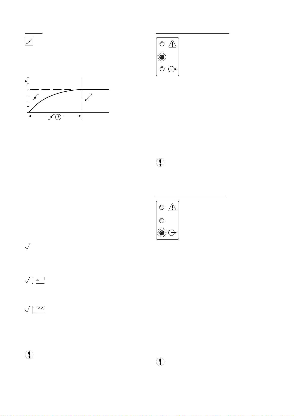
PRESSURE CHANGE TIME:
When the X12I is instructed to change between tables, it
will not abruptly change the system operating
parameters. The X12I will adjust the system target
pressure upward or downward to the next table’s
settings. This transition will occur gradually to preserve
energy efficiency and safe, reliable control:
Adjust the ‘day of the week’ sub-setting first and then
press Enter to increment to the next setting. Repeat until
all item sub-settings are entered. The complete ‘Pressure
Schedule’ item will not be set in X12I memory until the
last sub-setting is entered. Press Escape to step back
one sub-item if required.
SEQUENCE ROTATION:
1
The time the system is allotted to change the target
pressure is known as the Pressure Change Time (PC).
This is a value that is adjustable in the system settings
screen.
If the X12I is able to complete the transition in less time
than is allotted without threatening energy efficiency then
PC will be automatically shortened.
An aggressively short time setting will compromise
energy efficiency.
PRESSURE SCHEDULE:
The X12I is equipped with a real time clock feature
and pressure schedule facility. The ‘Pressure Schedule’
function can be used to provide automation of the
ystem. s
The pressure schedule consists of 28 individual settings
that instruct the system to change from one ‘Table’ to
another, or put the system in to ‘Standby’ mode,
dependant on time of day and day of the week. The
pressure schedule will cycle from 00:00 hours Monday
(day #1) to 23:59 hours on Sunday (day #7) each
alendar week. c
P01
01.0# 01
2
PC
Changing Target Pressures
A sequence ‘Rotation’ event can be automatically
triggered on a routine basis using a pre-determined
interval, a pre-determined time each day or a pre-
etermined day and time each week. d
S01
04.01 RP
#1 18:00
Enter the rotation period menu item (RP); the ‘day’
etting will flash. s
Select the ‘day’ or day function as required:
#1 = Monday to #7 = Sunday
#8 = each working day of the week, excluding Saturday
and Sunday
of the week. #9 = each working day
- (dash) = deactivate #
Select the required hour and minutes of the day(s) using
he same method. t
A day starts at 00:00hrs and ends at 23:59hrs (24hr
lock system). c
To define an interval time (more than one
rotation event a day) select ‘#t’ for the day function and
ress Enter: p
S01
04.02 RP
# - - - : - -
- - -
01 02 03040# =
01) Day of the Week
#1 = Monday to #7 = Sunday
#8 = every working day of the week; Monday to
ay. Friday, excluding Saturday and Sund
#9 = every working day of the week.
Select “-“ (dash) and enter to delete a setting from
he schedule. t
4hr format) 02) Hours; time of day (2
03) Minutes; time of day
04) The required table, T01 to T04, or
“-X-“ = Standby (unload all compressors).
# t 12:00
2
An ‘intervals per day’ value will appear and flash. Select
the required number of rotation events per day (1 to 96).
The hour and minutes display will now show the interval
time between each rotation event; 1 = every 24hrs to 96
every 15 minutes (example: 2 = every 12hrs). =
The first automated rotation event each day will
occur at 00:00hrs and then every set rotation interval
time throughout the day.
26
Page 27
PREFILL
The Prefill feature provides a controlled and energy
efficient method of increasing pressure to normal
operating levels at system start. This feature avoids the
inefficient potential for all available system compressors
to start and load before pressure reaches the normal
perating level. o
At system start (manual start or automated start from
standby) the X12I will only load compressors that have
been pre-determined for prefill operation, for a pre-set
period of time. The prefill time (PT) can be adjusted to
suit system characteristics. The aim is to increase
pressure to normal operational levels, using only the pre-
etermined compressors, prior to the prefill time expiring. d
If normal operational pressure is reached prior to the set
prefill time, the prefill function will automatically cease
and normal operational control begin. If normal
operational pressure is not reached by the end of the
prefill time, the X12I will utilize as many available
compressors as required to achieve normal operational
pressure as quickly as possible. Normal operational
ontrol will then begin. c
Three prefill modes are available. ‘Backup’ and
‘Standard’ modes require compressor pre-selection and
function in the same way; differing only in response to a
failure, or loss, of a prefill compressor. Automatic mode
equires no compressor pre-selection. r
Backup Mode: Compressor(s) can be pre-selected as
‘Primary Prefill’ compressor(s) or ‘Backup Prefill’
compressor(s). If a primary prefill compressor
experiences a shutdown, or is stopped, a pre-defined
ackup compressor replaces it and prefill continues. b
! X
Standard Mode: If one or more of the predefined prefill compressors experiences a shutdown, or is
stopped, the prefill function is cancelled and normal
peration begins. o
A
Automatic Mode: No Prefill compressor
selection is necessary; any selection set is ignored. The
management unit automatically selects compressor(s)
dynamically to achieve pressure in accordance with the
set Prefill time. If a compressor is stopped, or shuts
down, it is automatically substituted with an alternative
ompressor. c
To manually skip Prefill mode, press and hold Start
or several seconds. f
INSUFFICIENT CAPACITY ALARM
CAP
The X12I is equipped with a dedicated ‘Insufficient
Capacity’ Advisory Alarm (Warning) indication. This
indication will illuminate if all available compressors are
loaded and system pressure is continuing to decrease.
The indication will generally occur prior to any set low
pressure Alarm (Warning) and is intended to provide an
dvanced warning of a potential ‘Low Pressure’ situation. a
The ‘Insufficient Capacity’ advisory alarm is intended as
an advanced warning and is not recorded in the fault
history log but is included as a Group Alarm (Warning), or
roup Fault item. G
‘Insufficient Capacity’ is available as a dedicated data
communications item.
can be de-activated. In this instance the unit’s Alarm
indicator will still illuminate but no group alarm, group
fault, or a remote indication is generated.
RESTRICTED CAPACITY ALARM
The ‘Insufficient Capacity’ advisory alarm function
CAP
The X12I is equipped with a dedicated ‘Restricted
Capacity’ Advisory Alarm (Warning) indication. This
indication will flash if all available compressors are
loaded and further capacity is required but one or more,
ompressors are: c
a) inhibited from use in a ‘Table’ priority setting
b) inhibited from use by the short-term Service /
Maintenance function
) inhibited from use in the long term maintenance menu. c
The ‘Restricted Capacity’ advisory alarm is intended to
indicate that all available compressors are already loaded
and further capacity is required but one or more, system
ompressor(s) have been restricted from use. c
The ‘Restricted Capacity’ advisory alarm is not recorded
in the fault history log but is included as a Group Alarm
(Warning), or Group Fault item.
‘Restricted Capacity’ is available as a dedicated data
ommunications item. c
be de-activated. In this instance the unit’s alarm indicator
will still flash but no group alarm, group fault, or a remote
indication is generated.
The ‘restricted capacity’ advisory alarm function can
27
Page 28
ALTERNATE CONTROL STRATEGIES
Energy Control Mode (ENER) is the STANDARD control
mode of the X12I. Alternate control strategies of the X12I
are EHR (Equal Hours Run) and the basic FILO (First in /
ast Out). L
EHR: EQUAL HOURS RUN MODE
The primary function of EHR mode is to maintain a close
relationship between the running hours of each
compressor in the system. This provides an opportunity
to service all compressors at the same time (providing
the service interval times for all compressors are the
ame or similar). s
EHR is not an energy efficient focused mode of
peration. o
EHR Rotation:
Each time the rotation interval elapses, or the rotation
time is reached, the sequence order of compressors is
reviewed and re-arranged dependant on the running
hours recorded for each compressor. The compressor
with the least recorded running hours is assigned as the
‘duty’ compressor, the compressor with the greatest
recorded running hours is assigned as the ‘last standby’
compressor. For systems with more than two
compressors, the remaining compressor(s) are assigned
in accordance with their recorded running hours in the
ame way. s
Example: The compressors in a four-compressor system
have the following recorded running hours at the
Rotation’ time. ‘
Compressor 1 = 2200 hrs
Compressor 2 = 2150 hrs
Compressor 3 = 2020 hrs
ompressor 4 = 2180 hrs C
The new sequence order arrangement after a rotation
vent would be: e
Compressor 1 = D
Compressor 2 = B
Compressor 3 = A
ompressor 4 = C C
Compressor 3, which has the least recorded running
hours, will now be utilized to a greater extent in the new
sequence arrangement; potentially increasing the running
ours at a faster rate. h
The X12I continuously monitors the running status of
each compressor and maintains a record of the
accumulated running hours. These are available, and
adjustable, in the X12I’s compressor running hour’s
menu. The X12I uses these values in EHR mode. The
X12I’s running hours record should be routinely checked,
and adjusted if necessary, to ensure a close match with
he actual run hours displayed on each compressor. t
If a compressor is operated independently from the
X12I the running hours record may not be accurately
updated.
The running hours meter display on most
compressors are intended for approximate service
interval indication only and may deviate in accuracy over
period of time. a
EHR Control:
Compressors are utilized, in response to changing
demand, using a ‘FILO’ (First In, Last Out) strategy. The
‘duty’ compressor (A) is utilized first followed by (B) if
demand is greater than the output capacity of (A). As
demand increases (C) is utilized followed by (D) if
demand increases further. As demand reduces (D) is the
first compressor to be unloaded, followed by (C) and then
(B) if demand continuous to reduce. The last compressor
to be unloaded, if demand reduces significantly, is (A).
The compressor assigned as (A) in the sequence is the
rst to be loaded and the last to be unloaded. fi
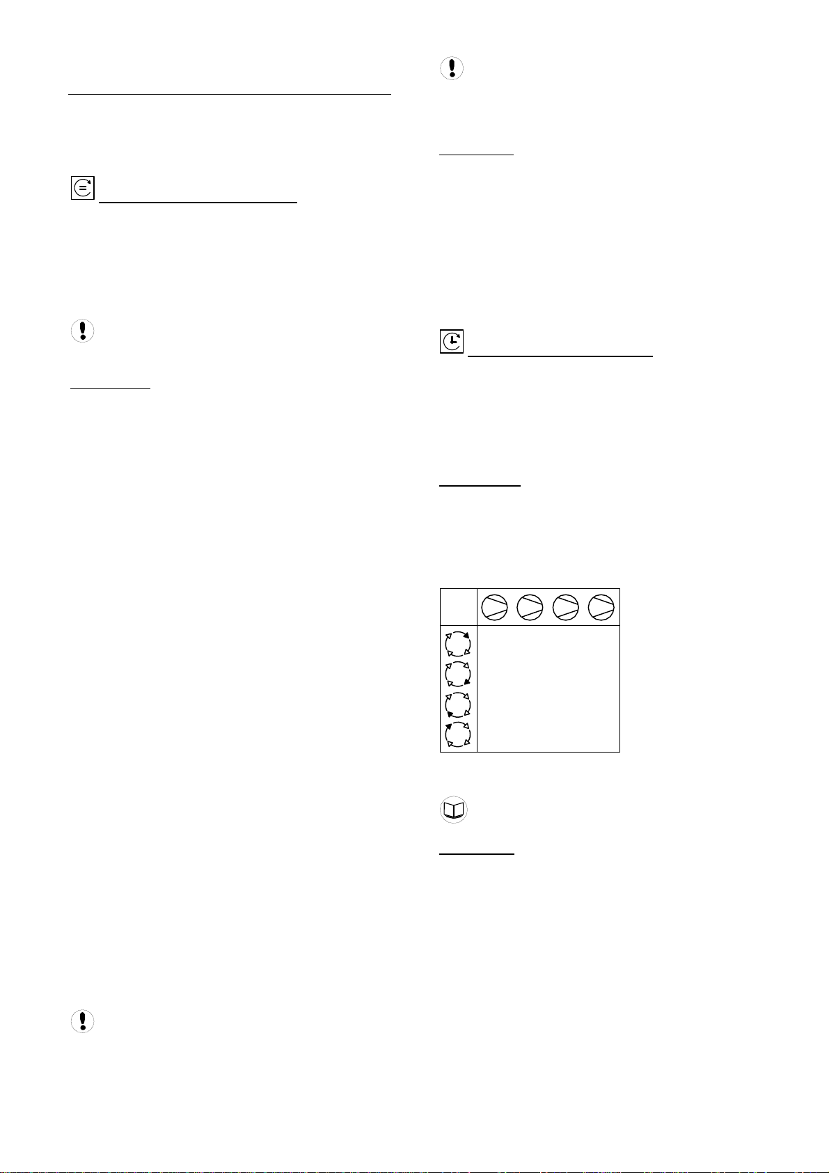
FILO: TIMER ROTATION MODE
The primary function of Timer Rotation mode is to
efficiently operate a compressed air system consisting of
fixed capacity output compressors. The routine rotation
assignments can be modified using ‘Priority’ settings to
accommodate for a differentially sized or variable
apacity output compressor(s). c
FILO Rotation:
Each time the rotation interval elapses, or the rotation
time is reached, a sequence rotation occurs and the
sequence assignment for each compressor is rearranged. The compressor that was assigned for duty (A)
is re-assigned as last standby (D) and all other
ompressor assignments are incremented by one. c
#1
#2
#3
#4
The sequence assignment pattern can be modified by
‘Priority’ settings.
Tables; Priority Settings
FILO Control:
Compressors are utilized, in response to changing
emand, using a ‘FILO’ (First In, Last Out) strategy. d
The ‘duty’ compressor (A) is utilized first followed by (B) if
demand is greater than the output capacity of (A). As
demand increases (C) is utilized followed by (D) if
emand increases further. d
As demand reduces (D) is the first compressor to be
unloaded, followed by (C) and then (B) if demand
continues to reduce.
The last compressor to be unloaded, if demand reduces
significantly, is (A). The compressor assigned as (A) in
the sequence is the first to be loaded and the last to be
unloaded.
1 2 3 4
ABCD
DABC
CDAB
BCDA
28
Page 29

ADDITIONAL CONTROL FEATURES AND
FUNCTIONALITY
ZONE CONTROL FUNCTION
Compressors can be assigned to one of three ‘zones’.
The X12I will always attempt to balance utilization across
the zones to maintain, as near as possible, an equal
umber of utilized compressors in each zone. n
2
PRESSURE BALANCE FUNCTION
rP1
P
rP2
1
3
This function is intended for installations that have
ultiple areas of compressor(s) distributed across a site. m
In some instances, large pressure differentials can
develop in remote areas of an air network if air
generation is concentrated in one area. The aim of the
‘zone’ function is to facilitate a balanced pressure across
a site air network by ensuring air generation is
istributed. d
The ‘zone’ function will operate with all available
sequence strategy modes and will work in conjunction
ith the priority and/or pressure balance function. w
The priority function will override ‘zone’ control
where a conflict in compressor selection occurs. This
may result in unexpected compressor utilization; this
hould not be considered abnormal. s
The X12I has the capability to monitor up to two remote
pressures values. These remote pressures can be
integrated with the primary X12I System pressure value,
using one of three available functions, to produce a
calculated ‘balanced’ system pressure for system
ressure control. The three functions to control from are: p
The lowest pressure
The highest pressure
An average of the X12I and the remote pressures
These pressure values can be obtained from Ingersoll
Rand compressor controllers, compressor management
boxes or I/O Boxes.
This function can be used to control to a ‘balanced’
system pressure across an air system that has multiple
remote compressor rooms and/or where pressure
ifferentials across an air system might vary. d
The ‘zone’ function can modify compressor selection
when using ‘Energy Control’ mode. This may
compromise optimum system efficiency in some
instances – use ‘zone’ control with caution where system
fficiency is important. e
29
Page 30

START FUNCTION:
The ‘Start’ function enables auxiliary equipment to be
pre-started prior to utilization of any compressors. The
function also monitors the auxiliary equipment during
normal running operation.
At system start-up (manual start or automated start from
standby) any output relay set for the ‘Start’ function will
energize. The management system will then wait for the
set ’Start’ time before utilizing any system compressors.
During this time the management system expects to
receive a feedback on the ‘Start Function Feedback
Input’. The management system response to the
feedback is dependent on the selected ‘Start’ function.
If feedback is not received by the end for the ‘Start’ time
the management unit can be set to display an Alarm
Warning) and continue, or Shutdown. (
If, at any time during normal operation, the feedback
signal disappears the management unit can be set to
isplay an Alarm (Warning) and continue, or Shutdown. d
This function is intended for automated control and
monitoring of auxiliary equipment critical to air
compressor system operation; air dryer(s) or cooling
water pump(s) for example.
VIRTUAL RELAY AUTOMATION
he X12I is equipped with Virtual Relay Automation. T
The ‘Virtual Relay’ concept is a configurable system-wide
automation system. The concept allows output relay
functions to be configured to respond to any ‘virtual relay’
condition, status or signal function available in the unit or
rom another compatible unit on the system network. f
Consult the X-Series Virtual Relay Automation
Manual for information regarding the use of Virtual Relay
utomation. A
Virtual Relay Automation
30
Page 31

SECTION 6 — DISPLAY AND MENU OPERATION
The Main Display and the keypad and navigation buttons
on the X12I are depicted below and provide the following
functionality
d
e
1
17:30 #1
a
102
b
PSI
c
a
b
CAP
c
a
b
c
a
f
b
g
c
d
1
h
e
31
Page 32

1
2
3
4
32
Page 33

MAIN MENU
USER MENU
A number of User menu information displays are
available that can be accessed directly from the front
panel using the Up and Down navigation buttons.
REAL TIME CLOCK:
17:30 #1
17:30 (24hr system)
#1 = Monday to #7 = Sunday
PRIMARY DETECTED PRESSURE:
102 psi
The pressure detected on the unit’s primary pressure
ensor. s
When using remote pressure balancing functions
the main display ‘control’ pressure may differ from the
rimary detected pressure. p
Pressure Balance Function
2ND PRESSURE INPUT:
101 psi
he second local pressure value. T
Only displayed if the 2nd Pressure sensor function is
nabled. e
COMPRESSOR DETAILED STATUS:
1
Compressor 1
100%’ percentage load ‘
tatus Symbol: S
Standby
Running, Offload
#
Alarm (Warning)
A: 100%
gnment ‘A’ (Duty) sequence assi
Running, Loaded
Removed From Service in Table Priority
Selection (# = Table Number)
Removed From Service in Long Term
Maintenance Menu
Removed From Service by Short Term IR-PCB
Maintenance Switch Function
2nd Pressure Sensor Input
DIFFERENTIAL PRESSURE:
3 psi
The differential pressure between the Primary and 2
ressure sensor inputs. P
Only displayed if the 2nd Pressure sensor function is
enabled and selected for air treatment pressure
ifferential monitoring. d
2nd Pressure Sensor Input
nd
Not Available, Shutdown (Trip), Stopped
Network Communications Error
(RS485 connectivity only)
The detailed status of each compressor in the system is
shown separately.
33
Page 34

REMOTE PRESSURE #1:
102 psi
The first remote pressure value from a remote source.
sed for the Pressure Balance Function. U
Only displayed if the Pressure Balance Function is
activated and the first remote pressure has been
elected. s
Pressure Balance Function
REMOTE PRESSURE #2:
100 psi
The second remote pressure value from a remote
source. Used for the Pressure Balance Function.
Only displayed if the Pressure Balance Function is
activated and the second remote pressure has been
elected. s
INFORMATION DISPLAYS
To view detailed information applicable to the
elected User menu display item press Enter. s
Press Escape to return to the normal user
enu display items.real time clock: m
P00
2
#1 18:30
T2
1
1
hows the next Pressure Schedule event. S
1: The Current Active Table
=Sunday) 2: Day (#1=Monday, #7
r system) 3: Time (24h
4: Table
Items 2 and 3 show the day and time that the unit
will change to use the ‘Table’ shown in item 4.
COMPRESSOR STATUS:
3
4
Pressure Balance Function
NEXT SCHEDULED SEQUENCE ROTATION:
00:00 #1
he next le : T schedu d sequence rotation
00:00 Time (24hr system)
#1 Monday
A setting of zero hundred hours (00:00hrs) on
Monday (#1) equates to a sequence rotation at one
econd past midnight on Sunday. s
P00
3
1
1
1
1
1: Compressor Number
2: Priority Setting
3: Zone Allocation Setting
4: Compressor/Connection Type
5: Maximum Capacity % Setting
6: Minimum Capacity % Setting
7: Minimum Efficiency % Setting
Item values 6 and 7 are only shown if compressor
type is IRV-485 (variable capacity/speed).
2
IRV-485
100 %
20 %
30 %
4
5
6
7
34
Page 35

PRIMARY DETECTED PRESSURE:
P00
102
1
1
98
80
1: Active Table
3: Lower (Load) Pressure Set Point
4: Minimum Pressure Alarm (Warning)
DIFFERENTIAL PRESSURE:
P00
3 psi
30 sec
P2(SYS)
1: Alarm (Warning) Level
ime 2: Alarm (Warning) Delay T
3: Source of 2
nd
Pressure
psi
psi
psi
2ND REMOTE PRESSURE:
P00
2
3
4
t 2: Upper (Unload) Pressure Set Poin
1
1: Source of 2
Only show if pressure balancing function active and
nd
remote pressure in use. 2
Pressure Balance Function
SEQUENCE ROTATION:
nd
Remote Pressure
B02
1
P00
2
#4 18:00
3
18 / 05 / 2006
A B C D
Only shown if the 2nd pressure sensor is activated in
air treatment pressure differential mode.
1ST REMOTE PRESSURE:
P00
B01
1: Source of 1
Only show if pressure balancing function active.
Pressure Balance Function
st
Remote Pressure
Day of the week (#4: Thursday), the time of
day (18:00) and the date (18/05/2006) of the next
utomated sequence rotation event. a
The active ‘mode’ of operation
“ABCD” The current active rotation sequence
assignment.
1
MANUAL SEQUENCE ROTATION:
The sequence assignment can be manually rotated at
any time. When viewing the ‘Sequence Rotation’
information screen press Enter:
The manual rotation symbols will appear and
flash. Press Enter again to execute a manual rotation or
scape to abandon the manual rotation. E
Automated sequence rotation is not disrupted by a
manual rotation; the next scheduled automated sequence
rotation event will still occur.
35
Page 36

INDICATOR LED’S
T he X12I Indicator LED’s are as follows.
Off
On
Intermittent:
1sec
Slow Flash:
1sec
Fast Flash:
1sec
UNIT INDICATORS
Unit Run Indicator (Green LED)
OFF – Not Active, Stopped
Slow Flash: Active, Standby Mode
ON – Active, Running
Unit Fault Indicator (Red LED)
Fast Flash: Shutdown (Trip)
Slow Flash: Alarm (Warning)
COMPRESSOR STATUS INDICATORS:
a
b
c
Each compressor in the system has a set of dedicated
status indicators. The indicators will continuously show
he status of each compressor at all times. t
) Load Status a
b ) Run Status
) Available (Started) c
1
OFF – Not Loaded, Offload
Slow Flash – The compressor has been
requested to load but is not loaded (load or reload delay period)
ON – Loaded
OFF – Not Running
Slow Flash – The compressor has been
requested to load but is not running (blowdown
delay or other start delay)
ON – Running
OFF – No Compressor Connected
Fast Flash – Not Available, Shutdown Fault or
Stopped
Slow Flash – Alarm (Warning)
Intermittent Flash – The compressor has been
intentionally removed from service.
Available, OK
The X12I fault indicator does not indicate
compressor fault states; see Compressor Status
Indicators.
36
Page 37

SYSTEM ALARMS (WARNINGS):
a
b
CAP
c
) Group Compressor Fault a
OFF – All Compressors OK
Fast Flash – One or more compressors Not
Available, Shutdown Fault or Stopped
Slow Flash – One or more compressors Alarm
(Warning)
b) Insufficient Capacity Alarm (Warning)
On – Insufficient Capacity
c) Restricted Capacity Alarm (Warning)
Slow Flash – Restricted Capacity
COMPRESSOR IDENTIFICATION
Each compressor connected to the X12I will have a
unique assigned compressor identification number;
starting at compressor 1 increasing sequentially to the
umber of compressors connected to the X12I. n
A: 85%
The design of some air compressor control systems
may inhibit automatic transfer of pressure regulation
control to local operation mode. In this instance the
compressor will not continue production of compres
air – consult the air compressor manual or your air
compressor supplier /
installing the IAX4.
START:
f the ‘Start Function’ is enabled there will be a periI
ti
Start for several seconds.
If the Prefill function is enabled, and system pressure is
mode
Start for several seconds.
normal operating mode.
and o
To start the X12I press Start.
ore any compressor is requested to load. me bef
Start Function
To manually skip the Start function, press and hold
elow the set prefill pressure,b
for the set Prefill time.
Prefill
To manually skip the Prefill function, press and hold
hen Prefill is complete, ifW
he X12I will operate in accordance wT
ptions set in the active ‘Table’.
specialist for details before
the system will enter Prefill
applicable, the X12I will enter
ith the parameters
sed
od of
12 34
X12I CONTROL KEYPAD FUNCTIONS
STOP:
To stop the X12I press Stop.
The X12I will respond dependant on the setup of item
CF’ in menu S02: ‘
Pressure regulation control is automatically
transferred back to each compressor. The compressor(s)
will continue to operate using the pressure settings
programmed or set in the individual compressor
controller(s).
The X12I will hold each compressor in an offload
state. If the compressor is equipped with a main motor
run-on-time function the compressor will run offload for a
period of time and then stop in to a ‘standby’ or ‘auto
estart’ state. r
Tables
Each compressor in the system must be started
(running or in a standby or auto restart condition) before
X12I control of the compressor can be established. T
X12I will no
condition.
POWER FAILURE AUTO-RESTART
t start a compressor that is in a stopped
he
If the power failure auto-restart function is
enabled the X12I will automatically start, when
power is restored after a disruption or failure,
X12I was in a ‘started’ state wh
en the power
if the
disruption or failure occurred.
The X12I will not automatically restart if the X12I
was in a stopped sta
o
r failure occurred.
te when the power disruption
37
Page 38

FAILURE MODE
If the X12I experiences a disruption to normal control, or
an X12I shutdown fault occurs, pressure regulation
control is automatically transferred back to each
compressor. The compressor(s) will continue to operate
using the pressure settings programmed or set in the
individual compressor controller(s).
RESET
To reset an X12I Alarm (Warning) or
hutdown condition press Reset. S
Compressor Alarm (Warning) conditions are
automatically reset when the condition has been resolved
nd reset on the compressor. a
Compressor Not Available (Shutdown, Trip) conditions
are automatically reset when the condition has been
resolved and reset on the compressor; and the
compressor has been restarted.
38
Page 39

SECTION 7 — COMMISSIONING
When commissioning the X12I, carry out the following
rocedures before attempting to start.
p
It is recommended that an authorized and trained
product supplier carry out commissioning.
PHYSICAL CHECKS
Before applying power to the X12I ensure that the power
supply connections are correct and secure and that the
operating voltage selector is set correctly for the power
supply voltage in use; 115Vac or 230Vac (+-10%),
0/60Hz.
5
Open the front panel of the X12I and check the location
of the link(s) connected to the ‘Voltage Selection’
terminals of the power supply PCB. If necessary, change
the link wire locations to those illustrated for the voltage
n use. i
X12I QUICK SET-UP CONFIGURATION
Before successful basic operation can be established
specific parameters must be entered prior to startup.
Please refer to the X12I Quick Setup Manual for
struction to accomplish this.
in
OPTIONAL FEATURES AND FUNCTIONS
Installation requirements may involve the implementation
of additional or optional functions and features. Please
efer to the appropriate Guide or Manual as required. r
Installation
witch on the power supply to the X12I. S
The control program identification will be displayed for a
short period followed by the normal operational User
display.
PRESSURE DISPLAY
Check the displayed system pressure. If the pressure is
incorrect, or inaccurate, check the type and range of the
sensor and carry out the pressure sensor commissioning
and calibration procedure. If the display shows an error,
his will need to be corrected before continuing. t
Menu Navigation
Menus and Menu Items
S04 – 1O Sensor Offset Calibration
04 – 1R Sensor Range Calibration S
39
Page 40

SECTION 8 — SYSTEM CONFIGURATION
DISPLAY ITEM STRUCTURE
All operational system status and values are accessible
from the normal User display. To view status or values,
that are not normally visible on the default screen, press
UP or DOWN. All standard User display items are view
only and cannot be adjusted. The standard User display
ems are regarded as ‘Menu Page 00’ items. it
All adjustable value, parameter or option item displays
are grouped into ‘menu mode’ lists. Items are assigned to
a list according to type and classification. Item lists are
identified by page number (or menu number); All
adjustable parameters and options are assigned to menu
mode pages ‘P01’ or higher.
NORMAL OPERATIONAL DISPLAY
(MENU PAGE P00):
At controller initialization, all LED indicators are switched
on for several seconds before initialization is complete
and the normal operating display (Page P00) is shown. In
normal operational display mode the main display will
continuously show the detected system pressure and the
Item display will show the first item of the ‘Page 00’
menu. User menu ‘Items’ can be selected using the Up or
Down buttons at any time. Pressing the Enter button will
lock any selected Item display and inhibit return to the
default display. When an Item display is locked the lock
key symbol will be shown. To unlock an Item display
press Up or Down to view an alternative Item display or
press Reset or Escape. No Item values, options or
parameters can be adjusted in page ‘P00’. If a fault
condition occurs the fault code becomes the first list item
and the display will automatically jump to display the fault
code. More than one active fault code item can exist at
any one time and can be viewed by pressing UP or
DOWN. The most recent ‘active’ fault will be at the top of
he list. t
ACCESSING THE X12I CONFIGURATION
SCREENS
ACCESS CODE:
Access to adjustable menu page items is restricted by
access code. To access menu mode pages press MENU
(or UP and DOWN together); an access code entry
isplay is shown and the first code character will flash. d
0 0 0 0
Use UP(plus) or DOWN(minus) to adjust the value of the
first code character then press ENTER. The next code
character will flash; use UP or DOWN to adjust then
press ENTER. Repeat for all four code characters.
If the code number is less than 1000 then the first code
character will be 0(zero). To return to a previous code
character press ESCAPE. When all four code characters
have been set to an authorized code number press
ENTER. An invalid code will return the display to normal
perational mode; page ‘P00’. o
Access Code Accepted
Access Code Rejected
Access Code Timeout:
When in menu mode, if no key activity is detected for a
period of time the access code is cancelled and the
display will automatically reset to the normal operational
isplay. d
enu Mode Navigation: M
In menu mode the menu ‘page’ number will be
ighlighted at the top of the display. h
P00
To select a menu ‘page’ press UP or DOWN. To enter
the highlighted menu ‘page’ press ENTER; the first item
of the menu ‘page’ will be highlighted. Press UP or
OWN to scroll though the selected menu ‘page’ items. D
40
Page 41

To select an item value or parameter for modification,
press ENTER; an adjustment screen for the item will be
isplayed. d
The value or option can now be modified by pressing
UP(Plus) or DOWN(Minus). To enter a modified value or
ption in to memory, press ENTER. R. o
Page 0
Item 1 Value
Item 2 Value
Item 3 Value
Item 4 Value
Item 5 Value
Item 6 Value
Press ESCAPE at any time in menu mode to step
Press ESCAPE at any time in menu mode to step
backwards one stage in the navigation process. Pressing
backwards one stage in the navigation process. Pressing
ESCAPE when the page number is flashing will exit
ESCAPE when the page number is flashing will exit
menu mode and return the display to normal operational
menu mode and return the display to normal operational
ode.
ode.
mm
Page 0
All menu items have a unique reference consisting of the
All menu items have a unique reference consisting of the
menu page ID (a) and the menu page item number (b).
menu page ID (a) and the menu page item number (b).
Each item in a menu also has a unique two alphanumeric
Each item in a menu also has a unique two alphanumeric
character code (c). All three references are visible at the
character code (c). All three references are visible at the
op of every menu item display. t t
op of every menu item display.
Item 1 Value
Item 2 Value
Item 3 Value
Item 4 Value
Item 5 Value
Item 6 Value
Page 1
Page 2
Page 3
Page 4
Page 5
Page 1
Page 2
Page 3
Page 4
Page 5
Item 1 Value
Item 2 Value
Item 3 Value
Item 4 Value
Item 5 Value
a b c
P01P01
Some menu items may consist of several individual
settings. Each setting of the menu item is also referenced
as a sub-item number. For example: P01-01.02
references sub-item ‘02’ of menu item ‘01’ in menu page
‘P01’. Sub-item settings, where applicable, are always
displayed together on the same ‘Item’ adjustment display
screen. Most menu items are single value or single
option only in which case the single item is referenced as
sub-item number ‘01’ (for example: P01-01.01).
01.02 AB
Item 1 Value
Item 2 Value
Item 3 Value
Item 4 Value
Item 5 Value
Press and hold RESET for several seconds at any
time to immediately exit menu mode and return to the
normal operational display. Any value or option
adjustment that has not been confirmed and entered into
memory will be abandoned and the original setting
aintained. m
The X12I will retain an ‘access code’ for a short
period after menu exit allowing the menu structure to be
re-entered without the need to re-enter the access code
again. To immediately clear access code retention press
nd hold RESET for several seconds. a
A ‘locked’ symbol displayed with any item
indicates the item is locked and cannot be modified.
This will occur if the Item is view only (not
adjustable) or in instances where the item cannot
be adjusted while the X12I is in an operational
state; stop the X12I first.
41
Page 42

USER LEVEL MENUS
1
TABLE #1
T01
01 PH High Pressure Set Point
02 PL Low Pressure Set Point
rm 03 Pm Minimum Pressure Ala
Sequence Algorithm 04 SQ
01 Compressor #1 Priority 05
to
16 12 Compressor #12 Priority
TABLE #2 to #6 (as Table #1)
Pressure Schedule
P01
01 01 Schedule Setting #1
to
28 28 Schedule Setting #28
Prefill
P02
01 PF Prefill Function
02 PT Prefill Time
03 PP Prefill Pressure
01 Compressor #1 04
to
15 12 Compressor #12
User Configuration
S01
01 Ct Real Time Clock Set
nable 02 PS Pressure Schedule E
le 03 AR Auto Restart Enab
04 RP Rotation Interval
05 TS Default Table Select
06 BL Display Backlit Adjust
Compressor Running Hours
C01
01 01 Compressor #1 Running Hours
to
12 12 Compressor #12 Running Hours
Compressor Maintenance
C02
01 01 Compressor #1 Maintenance
to
12 12 Compressor #12 Maintenance
Fault Log
E01
01 01 Fault Log #1 (most recent)
to
15 15 Fault Log #15
42
Page 43

SERVICE LEVEL MENUS (0021)
Configuration
S02
01 P> Pressure Units
02 F> Air Flow Units
04 NC Number Of Compressors
rm 05 PM Maximum Pressure Ala
l Function 06 CF Stop Contro
07 TO Tolerance
08 DA Damping
09 ST Start Delay Time
10 SF Start Function
11 PC Pressure Change Time
sure Function 12 P2 Second Pres
13 DP DP Setting
14 DD DP Delay Time
15 CA CAP Alarm Inhibit
Max Cap Restricted Alarm Inhibit 16 MA
unction 17 D1 Digital Input #1 F
18 ER Error Log Reset
Auxiliary Box Monitoring
S03
01 Auxiliary Box #1 Enable 01
To
Enable 12 12 Auxiliary Box #12
13 BT RS485 Timeout
Sensor Calibration
S04
01 1O Pressure Offset
02 1R Pressure Range
03 2O Pressure 2 Offset
nge 04 2R Pressure 2 Ra
05 FO Flow Offset
06 FR Flow Range
07 DO Dewpoint Offset
08 DR Dewpoint Range
Pressure Balance
S05
its 03 T> Dewpoint Temperature Un
elect 01 AF Aux Pressure Function S
02 P1 Aux Pressure #1 Source
03 P2 Aux Pressure #2 Source
04 D1 Aux Pressure #1 Deviation Limit
t 05 D2 Aux Pressure #2 Deviation Limi
06 D+ Max + Aux Pressure Deviation
ation 07 D- Min - Aux Pressure Devi
08 1O Aux Pressure #1 Offset
09 1R Aux Pressure #1 Range
10 2O Aux Pressure #2 Offset
11 2R Aux Pressure #2 Range
Compressor Configuration
C03
01 Compressor #1 Configuration 01
to
12 12 Compressor #12 Configuration
Compressor Zone
C04
01 Compressor #1 Zone Select 01
To
12 12 Compressor #12 Zone Select
43
Page 44

HIGH LEVEL MENUS (0032)
Relay Functions
R01
01 01 Relay #1 Function
02 Virtual Relay #02 Function 02
to
16 16 Virtual Relay #16 Function
Timer Relay Functions
R02
01 T1 Timer Relay #1
02 T2 Timer Relay #2
03 P1 Pulse Relay #1
04 P2 Pulse Relay #2
Pulse Relay #3 05 P3
06 P4 Pulse Relay #4
elay 07 AF Compressor Available R
08 RF Compressor Run Relay
09 LF Compressor Load Relay
Diagnostic Menu 1
D01
D1 Digital Input #1 (Di 1) 01
to
08 D8 Digital Input #8 (Di 8)
R1 Output Relay #1 (R1) 09
to
14 R6 Output Relay #6 (R6)
15 A1 Analog Input #1 (Ai1)
16 A2 Analog Input #2 (Ai2)
Analog Input #3 (Ai3) 17 A3
18 Ao Analog Output (Ao)
Diagnostic Menu 2
D02
01 SI Screen Invert
02 LT LED Panel Test
enu 3 Diagnostic M
XPM-Di8R4
D03
D1 Digital Input #1 (Di 1) 01
to
08 D8 Digital Input #8 (Di 8)
R1 Output Relay #1 (R1) 09
to
12 R4 Output Relay #4 (R4)
D04
D04
Diagnostic menu D04 has no standard function and is
ot shown. n
Diagnostic Menus 5 and 6
D05
D05: XPM Expansion Module C:5-8
only available when applicable XPM Expansion
odule fitted and registered. M
D06
D06: XPM Expansion Module C:9-12
only available when applicable XPM Expansion
odule fitted and registered. M
Diagnost
XPM-Ai4
D07
01 A1 Air Flow Sensor; 4-20mA
nd
ic Menu 7
A 02 A2 2 Pressure Sensor; 4-20m
mA 03 A3 Dewpoint Sensor; 4-20
ut D04 A4 Digital Inp i2; VDC
<0.5VDC
>20.0VDC
44
Page 45

X12I CONFIGURATION SCREENS
T01
12
01
PH
02
03
04
#
= Table T01 to T06
T0# – PH High Pressure Set Point
The ‘upper’ or ‘unload’ pressure set point that will be
used when the ‘Table’ is active. The default setting for
this parameter is 102 PSI. The values for this parameter
re: a
The highest value for the High Pressure Setpoint = PM
“Maximum Pressure Alarm” minus 2 times TO
Tolerance”. “
If PM is set for 145 PSI and TO is set for 3.0 PSI, then
the highest value for the High Pressure Setpoint would
e 139 PSI. b
The lowest value for the High Pressure Setpoint = PL
Low Pressure” Setpoint plus TO “Tolerance” “
If PL is set for 98 PSI and TO is set for 3.0 PSI, then the
lowest value for the High Pressure Setpoint would be 101
SI. P
T0# - PL Low Pressure Set Point
The ‘lower’ or ‘load’ pressure set point that will be used
when the ‘Table’ is active. The default setting for this
arameter is 98 PSI. The values for this parameter are: p
The highest value for the Low Pressure Setpoint = PH
High Pressure” Setpoint minus TO “Tolerance”. “
If PH is set for 102 PSI and TO is set for 3.0 PSI, then
the highest value for the Low Pressure Setpoint would be
9 PSI. 9
The lowest value for the Low Pressure Setpoint = Pm
“Minimum Pressure Alarm” Setpoint plus 2 times TO
Tolerance” “
If Pm is set for 80 PSI and TO is set for 3.0 PSI, then the
lowest value for the Low Pressure Setpoint would be 86
SI... P
PL
Pm
P1
Tables
102
98
90
1
16
psi
0
psi
psi
psi
T0# - Pm Minimum Pressure Alarm
The minimum pressure ‘Warning’ or ‘Alarm’ level that will
be used when the ‘Table’ is active. The default setting
for this parameter is 80 PSI. The values for this
arameter are:
p
The lowest Minimum Pressure Alarm Setpoint = “The
inimum range of the pressure transducer used.“
m
The highest Minimum Pressure Alarm Setpoint = “The
value from the Table PL – Low Pressure Setpoint” minus
times TO “Tolerance”” 2
If PL in Table 1 (T01) is set for 100 PSI and TO is set for
3.0 PSI, then the highest Minimum Pressure Setpoint
ould be 94 PSI. w
T0# - SQ Sequence Strategy
The sequence control strategy mode that will be used
when the table is active. The default setting for this
arameter is ENER. p
The values for this parameter are:
ENER – Energy Control Mode. The Rotation and
Control functionality of the ENER mode is to achieve
and maintain demand matched to optimum system
fficiency. e
FILO – First In Last Out. The Rotation and Control
functionality of the FILO mode is the first compressor
aded is the last compressor to be unloaded lo
EHR – Equal Hours Mode. The Rotation and
Control functionality of the EHR mode is to equalize
he Run Hours on all compressors t
T0# - 01 Compressor #1 Priority
The ‘priority’ setting for compressor number 1 that will be
sed when the table is active. u
o T
T0# -
‘n’ Compressor #’n’ Priority
The ‘priority’ setting for compressor number
e used when the table is active. b
‘n’ = number of compressors in the system. 12 is the
maximum number of compressors for the X12I
Priority Settings:
: compressor(s) can be inhibited from use while a table
is active by selecting “X” priority. The compressor will be
held offload and will not be utilized under any
circumstances.
’n’ that will
45
Page 46

P01
P02
28
28
- . - - : - - - - -
01 01 - . - - : - - - - -
02
02
03
03
04
04
Pressure Schedule
P01 – 01 to 28
The ‘Pressure Schedule’ items 01 to 28. The Pressure
Schedule consists of 28 individual settings that instruct
the X12I to change from one Table to another, or put the
system into Standby mode, dependant on time of day
and day of the week. The default setting for this
parameter is -. --:-- - - - . (Represents the Pressure
Schedule is disabled) The values for this parameter are:
from left to right) (
Day of the Week. The values for this parameter are:
“1” for Monday to “7” for Sunday (a specific day
of the week)
“8” for every working day of the week (every
day, Monday through Friday, excluding
Saturday and Sunday)
“9’” for every working day of the week (every
day, Monday through Sunday)
“–“ represents the Pressure Schedule is
disabled.
Hours (Military Time). The values for this parameter
are:
“00” to “23” the hours in a day
“–-“ represents the Pressure Schedule is
disabled.
Minu are: tes. The values for this parameter
“0” to “59”. the minutes in the hour
“–-“ represents the Pressure Schedule is
disabled.
Table / Standby mode selection. This instructs the
system to change from one ‘Table’ to another, or put
the system in to ‘Standby’ mode for the Pressure
Schedule. The values for this parameter are:
“T01”, “T02”, “T03” or “T04” for the 4 different
Tables
“–
– “ for Standby Mode
“–––“ represents the Pressure Schedule is
disabled.
- . - - : - - - - -
- . - - : - - - - -
- . - - : - - - - -
11
08
X
01 PF X
02
PT
03
PP
04
01
Prefill
P02 - PF Prefill Function
Determines the ‘Prefill’ strategy or function that will be
used at system startup. The default setting for this
parameter is
in Automatic Mode) The values for this parameter are: is
= Prefill function OFF
“
”= Prefill, Back-up Mode
Compressor(s) can be pre-selected as ‘Primary
Pre-fill’ compressor(s) or ‘Backup Pre-fill’
compressor(s). If a primary pre-fill compressor
experiences a shutdown, or is stopped, it is
replaced by a pre-defined backup compressor
and pre-fill continues.
! X
If one or more of the pre-defined pre-fill
compressors experiences a shutdown, or is
stopped, the pre-fill function is cancelled and
normal operation begins.
A
No Prefill compressor selection is necessary;
any selection set is ignored. The management
unit automatically selects compressor(s)
dynamically to achieve pressure in accordance
with the set Prefill time. If a compressor is
stopped, or shuts down, it is automatically
substituted with an alternative compressor.
P02 - PT Prefill Time
The Pre-fill Time Setpoint (in minutes) sets the maximum
time allowed for a system to start and load the
designated Compressor/s to increase system pressure to
normal operational levels. The default setting for this
parameter is – . (Represents the Prefill is disabled) The
alues for this parameter are: v
“–” the Pre-fill Time is Off
“1 to 120” the number of minutes
A
= Prefill, Standard Mode
= Prefill, Automatic Mode
. (Represents the pre-fill function
0
X
-
MIN
psi
46
Page 47

P02 - PP Prefill Pressure
The Pressure Setpoint used by the X12I to determine if
the Pre-fill Function is required at start up. If pressure is
at, or above, this setting at system startup, the prefill
function will be abandoned immediately and normal
pressure control and sequence strategy will be
implemented. This setting is intended to inhibit ‘Prefill’
operation if pressure is already at an acceptable level at
system startup. The default setting for this parameter is
PS. The values for this parameter are: 0
0 to 232 (or the maximum scaled pressure value
used by the X12I if a different Pressure
Transducer range is used)” the PSI value for the
Pre-fill Pressure
P02 – 01 to
‘n’
= number of compressors in the system. 12 is the
maximum number of compressors for the X12I
This parameter set the function of compressor 1 to
during the ‘Prefill’ period. The default for this parameter
is
refill Function) The values for this parameter are: P
“
fill Function
‘n’ Compressor 1 to ‘n’
‘n’
. (Represents this compressor is not used by the
”” for this compressor will not be used by the Pre-
“
” for this compressor will be used as a primary
compressor by the Pre-fill Function
“!” for this compressor will be used as an emergency
Backup compressor by the Pre-fill Function
These settings are applicable to Prefill – Standard
and Prefill - Back-up modes only. In Automatic mode the
system management unit dynamically utilizes
compressors as required.
Press and hold ‘Start’ for 5 seconds to manually
skip Prefill mode at start up.
47
Page 48

06
BL
S01
5
01 Ct 1 . 18:00
02
PS
03
AR
04
RP
Features and Functions
S01 - Ct Real Time Clock Set
(Hours, Minutes, Date, Month, Year)
The ‘Day of the Week’ (1= Monday to 7=Sunday) is
automatically calculated and set in accordance with the
Day, Month and Year. The default setting for this
parameter is - --.--. (Represents the clock has not been
nitialized)) The values for this parameter are: i
• “1” to “7” the ‘Day of the Week’ (1= Monday to
7=Sunday) which is automatically calculated
and set in accordance with the Day, Month and
Year entered.
• “00” to “23” the Hour for the Real Time Clock.
• “0” to “59” the Minutes for the Real Time Clock.
• “1” to “31” the Day for the Real Time Clock.
• “1” to “12” the Month for the Real Time Clock.
• “2005” to “2100” the Year for the Real Time
Clock.
S01 - PS Pressure Schedule Enable
This parameter enables or disables the Pressure
Schedule function in the X12I. The default setting for this
parameter is
disabled) The values for this parameter are:
= inhibit Pressure Schedule
= enable Pressure Schedule
S01 - AR Auto Restart Enable
This parameter enables or disables X12I restart function
after a power loss. When enabled, after a power
disruption or failure, the X12I will automatically restart
when power is restored if the X12I was in an operational
‘Started’ state when the power loss or disruption
occurred. The X12I will not automatically restart if the
X12I was in a “Stopped” state when the power disruption
or failure occurred. The default setting for this parameter
is
. (Represents the Auto Restart is enabled) The
alues for this parameter are: v
= inhibit Power Failure Auto Restart
= enable Power Failure Auto Restart
S01 - RP Rotation Interval
The X12I provides a Timed rotation event that can be
automatically triggered on a routine basis using a predetermined interval, a pre-determined time each day, or a
pre-determined day and time each week. The default
setting for this parameter is 1 00:00. (Represents a
otation at Monday (1) at 00:00 hours) r
1 . 00:00
. (Represents the Pressure Schedule is
X
lock. Adjustment for the internal real time c
T he values for this parameter are:
• “1” for Monday to “7” for Sunday (a specific day
of the week)
• “8” for every working day of the week (every
day, Monday through Friday, excluding
Saturday and Sunday)
• “9’” for every day of the week (every day,
Monday through Sunday)
• “t” for an interval of time (more than 1 or more
rotations per 24 hours)
• “–“ for disabling the Rotation Interval
If the parameter chosen above is “1” to “9”, you will need
to set the time for the rotation to occur. It is in a Military
ime format. The values for this parameter are: T
• “00” to “23” the Hour
• “0” to “59” the Minutes
• “–“ the Rotation Interval is disabled.
If the parameter chosen above is “t”, you will need to set
the Interval Time. This sets the required number of
rotation events per day (1 to 96). The values for this
parameter are:
• A value of 1 = rotate every 24 hours
• A value of 2 = rotate every 12 hours
• A value of 3 = rotate every 8 hours
• A value of 4 = rotate every 6 hours
• A value of 6 = rotate every 4 hours
• A value of 8 = rotate every 3 hours
• A value of 12 = rotate every 2 hours
• A value of 24= rotate every 1 hours
• A value of 48 = rotate every 30 minutes
• A value of 72 = rotate every 20 minutes
• A value of 96 = rotate every 15 minutes
• “–“ the Rotation Interval is disabled.
S01 - TS Default Table Select
This parameter determines the ‘Table’ that will be used
by default when ‘Pressure Schedule’ is not active and no
table is selected remotely on a digital input. The default
setting for this parameter is T01. The values for this
para etem r are:
• for Table T01 “T01”
• to
• “T06” for Table T06
S01 - BL Display Backlight Adjust
This parameter adjusts the backlight level for the display.
The display will temporarily increase brightness by 2
levels when a key is pressed and return to normal setting
after a period of no keypad activity. The default display
backlight level has been set to enable a ‘continuous use
service life’ in excess of 90000 hours while providing
good readability in all ambient light conditions. LCD
display ‘service life’ is defined as the time period before
the backlight reduces to 50% of initial brightness.
Typically the display will remain usable for a much longer
period of time. Adjusting the backlight to high levels will
reduce service life. The default setting for this parameter
5. The values for this parameter are: is
• “1” to “7” 1 being the least amount of
backlight and 7 being the most.
48
Page 49

18
ER
01 P>
02
F>
03
T>
04
NC
Pressure Control; Tables
S02 - P> Pressure Units
This parameter selects the display and operating
pressure units: The default setting for this parameter is
PSI. or this parameter are: The values f
• “PSI”
• “BAR”
• “kPA”
S02 - F> AirFlow Units
This parameter selects the display and operating AirFlow
units: The default setting for this parameter is CFM. The
values for this parameter are:
• “Cfm”
• “m3/min”
S02 - T> Temperature Units
This parameter selects the display and operating
Temperature units: The default setting for this parameter
o
is
F. The values for this parameter are:
o
• “
F”
o
• “
C”
S02 - NC Number of Compressors
This parameter sets the number of compressors
connected to, and controlled by, the X12I. This value
must be set to match the system at commissioning. The
default setting for this parameter is 4. The values for this
parameter are:
• “1” for 1 compressor
• “2” for 2 compressors
• “3” for 3 compressors
• “4” for 4 compressors
• To
• “12” for 12 compressors
S02
X
psi
cfm
o
F
3
S02 – PM: Maximum Pressure Alarm
This parameter sets the High pressure ‘Fault’ level. This
value remains active at all times and is the same for all
‘Tables’. It should be set just below system pressure
relief value(s) and below the maximum system pressure
rating of all air system components. The default setting
for this parameter is 145. The values for this parameter
re: a
• The highest value for the Maximum Pressure
Alarm Setpoint = “The maximum range of the
pressure transducer used”
• The lowest value for the Maximum Pressure
Alarm Setpoint = “The highest value from any
Table “PH - Pressure High” Setpoint plus 2
time hes t “To – Tolerance”
o If PH in Table 1 (T01) is set for 100
PSI, and PH in Table 2 (T02) is set for
110 and TO is set for 3.0 PSI, then the
lowest Maximum Pressure Setpoint
would be 116 PSI.
S02 - CF Stop Control Function
This parameter determines if the X12I maintains control
of the compressors when the X12I is stopped. The
default setting for this parameter is
Stop Control Function is disabled) The values for this
arameter are: p
= Stop: return pressure control to the
compressors.
= Standby: maintain control and continuously
hold compressors ‘off load’.
S02 - TO Tolerance
This parameter sets the pressure control ‘Tolerance’
band setting. The Tolerance Band setting is a pressure
band above and below the Load and Unload pressure
band. This accommodates for an instance of abrupt
and/or significant increase or decrease in demand
without compromise to optimal energy efficient control.
The X12I incorporates a Rate of Change algorithm in the
Tolerance Band to determine when a compressor should
be Loaded or Unloaded. The default setting for this
parameter is 3.0 PSI (.2 Bar) The values for this
arameter are: p
“1.4 PSI (.1 Bar)” for the minimum Tolerance Band
29.0 PSI (2 Bar)” for the maximum Tolerance Band “
• If air system storage is generous, the rate of the
pressure change is slow, and/or demand
fluctuations are insignificant and gradual, then
the ‘Tolerance’ band can be decreased to
improve pressure control without compromise to
optimum energy efficiency. As the Tolerance
Band is decreased, the Loading and Unloading
• If air system storage is inadequate, the rate of
the pressure change is fast, and/or demand
fluctuations are significantly large, the
‘Tolerance’ band can be increased to maintain
optimum energy efficiency, and reduce overreaction, during such transition periods. As the
Tolerance Band is increased, the Loading and
Unloading of compressors while in the band is
less rapid.
. (Represents the
. of compressors while in the band is more rapid
49
Page 50

S02 - DA Damping
This parameter sets the pressure control ‘Damping’
setting. Changing this parameter adjusts the time before
an additional compressor is loaded in accordance with
the urgency of the situation to increase air system
capacity further. The X12I has a dynamic reaction
algorithm that is pre-set by default to accommodate for
the majority of installation characteristics. If an increase
or decrease in the Tolerance band is insufficient, the
reaction response can be influenced by increasing or
decreasing the ‘Damping’ factor. The default setting for
this parameter is 1.0. The values for this parameter are:
1 TO 10 .
“.1”, the fastest Damping reaction time (10 times
aster than the default of 1.0) f
“10.0”, the slowest Damping reaction time (10 times
lower than the default of 1.0). s
• If air system storage is generous and the rate of
the pressure change is slow to rise, then the
‘Damping’ can be increased to improve pressure
control without compromise to optimum energy
efficiency. As the Dampening value is
increased, the Loading of additional
compressors is less rapid.
• If air system storage is inadequate and the rate
of the pressure change is fast to fall, then the
‘Damping’ can be decreased to improve
pressure control without compromise to
optimum energy efficiency. As the Damping
value is decreased, the Loading of additional
compressors is more rapid.
Damping also performs one more important function that
can arise in a system. When the system pressure
achieves stability in a position that may be outside of the
dead band but inside the tolerance band it will be allowed
to remain in this situation for a predefined amount of
time. This time limit depends on how far away from the
dead band the system pressure has stabilized. This
time limit is calculated as 30 min times the damping
constant at the top of the tolerance band and as 1 min
times the damping constant at the bottom of the
olerance band. t
02 – ST Start TimeS
Start Time
Sets the period of time, at system start, that the
management unit will wait for ancillary equipment to
tart/respond before loading any compressor. s
S02 – SF Start Function
Determines the function of the Start Time feature and the
reaction of the management unit to a failure of ancillary
quipment to respond within the Start Time. e
No Start Time Function
Management unit will wait for the full Start
Time regardless of feedback. If feedback does not occur
before Start Time expires the management unit will Trip
(shutdown). If the feedback disappears at any time during
peration the management unit will Trip (shutdown). o
Management unit will wait for the full Start
Time. The management unit will begin to utilize
compressor(s) as soon as feedback is received. If
feedback does not occur before Start Time expires the
management unit will Trip (shutdown). If the feedback
disappears at any time during operation the management
nit will Trip (shutdown). u
Management unit will wait for the full Start
ime regardless of feedback. T
If feedback does not occur before Start Time expires the
management unit will show an Alarm (Warning) and
begin to utilize compressor(s) as required. If the feedback
disappears at any time during operation the management
unit will show an Alarm (Warning).
Management unit will wait for the full Start Time.
The management unit will begin to utilize compressor(s)
as soon as feedback is received. If feedback does not
occur before Start Time expires the management unit will
show an Alarm (Warning) and begin to utilize
compressor(s) as required. If the feedback disappears at
any time during operation the management unit will show
an Alarm (Warning).
See S02-D1 ‘Start Function Feedback Input’ setting
SI). (
S02 - PC Pressure Change Time
This parameter adjusts the time that the X12I will
implement a smooth and controlled change from one
‘target’ pressure level to another when a table change is
made. The default setting for this parameter is 4 Min.
he values for this parameter are: T
“1”, 1 minute between Table target pressure Setpoint
hanges c
O T
“120”, 120 minutes between Table target pressure
Setpoint changes.
50
Page 51

02 – P2 Second P.Sensor FunctionS
P2=X:
Second pressure sensor function inhibit; no
sensor connected.
P1<>P2:
The system management unit will automatically
utilize the second pressure sensor (P2) in the
event of a primary pressure sensor (P1) failure.
The primary and secondary pressure
sensors must be installed to monitor the same
pressure at the same location.
P2=>DP:
The management unit will monitor and display the
differential pressure (DP) between the primary (P1)
nd secondary (P2) pressure sensors. a
The differential is displayed as a positive value
regardless of positive or negative relationship
between the sensors.
The system management unit will use the
primary pressure sensor (P1) for control.
S02 – DP DP Alarm Level
Differential pressure Alarm level when P2 set for
P”=>DP’ mode. ‘
DP and DD must be set to a value greater than
0(zero) to enable the Differential Alarm function. Set DP
nd DD to 0(zero) to inhibit the function. a
S02 – DD DD Alarm Delay
Differential pressure Alarm delay time (seconds) when
P2 set for ‘P”=>DP’ mode.
The set differential pressure must exceed, and remain
above, the differential pressure Alarm level for the delay
ime. t
DP and DD must be set to a value greater than
0(zero) to enable the Differential Alarm function. Set DP
nd DD to 0(zero) to inhibit the function. a
S02 – CA Capacity Alarm Enable
This parameter sets the functionality of the Capacity
Alarm. The default setting for this parameter is
(Represents the Capacity Alarm is enabled) The values
or this parameter are: f
= inhibit Capacity Alarm
= enable Capacity Alarm
When inhibited the Capacity Alarm panel indication
will still function; alarm code generation and remote
larm indications are inhibited. a
.
S02 – MA Restricted Cap. Alarm Enable
This parameter sets the functionality of the Restricted
Capacity Alarm. The default setting for this parameter is
. (Represents the Restricted Capacity Alarm is
nabled) The values for this parameter are: e
= inhibit Restricted Capacity Alarm
= enable Restricted Capacity Alarm
When inhibited the Restricted Capacity Alarm panel
indication will still function; alarm code generation and
emote alarm indications are inhibited. r
02 – D1 Auxiliary Digital Input D1S
S02
he function of the Auxiliary input. T
1:DI 0 Virtual Relay Digital Input
No defined function or action, but status
02:AA
03:AR Remote Alarm (active when unit running,
04:TA Remote Trip (always active)
05:TR Remote Trip (active when unit running, inhibited
6:SI Start Function Feedback Input 0
The selected function is activated when the input is
closed circuit (input terminals are connected together by
remote volt-free contacts)
The selected function is activated when the input is open
ircuit (input terminals are open circuit) c
S02 - ER Error Log Reset
This parameter clears and resets the ‘Error Log’. The
default setting for this parameter is
Error Log Reset is disabled)
he values for this parameter are: T
12.01 D1
NO
01:D1
(0=normal, 1=activated) can be used as a
‘Virtual Relay’ input function.
Remote Alarm (always active)
NO (Normally Open)
NC (Normally Closed)
“
” Error log reset is disabled
“ Error log reset enabled. Adjust the item setting
“
to ‘
’ and press ENTER. The display will return to
the main menu and all existing entries in the error
log will be permanently deleted.
r in Standby) inhibited when unit stopped o
y) when unit stopped or in Standb
. (Represents the
51
Page 52

S03
S04
X
X
X
X
sec60
13
BT
01 01
02
02
03
03
04
04
S03 – 01/12 I/O Box Monitoring
This parameter determines if the X12I will monitor the
selected I/O Box and display any ‘Fault’ detected on the
I/O Box inputs; dependant on I/O Box set-up. The default
setting for this parameter is
monitoring is disabled) The values for this parameter
re: a
= Disabled
= Enabled
Refer to I/O Box manual for details.
S03 – BT Communications Timeout
This parameter determines the Communication
Broadcast Timeout between the X12I and the I/O box. If
the I/O Box fails to communicate on the RS485 network
within the set ‘Communications Broadcast Timeout’ (BT),
the X12I will display an I/O Box RS485 communications
Error. The default setting for this parameter is 60
econds. The values for this parameter are: s
“10 to 300” the number of seconds
The general operation of the selected I/O Box is also
monitored. . If the I/O Box fails to communicate on the
RS485 network within the set ‘Communications
Broadcast Timeout’ (BT) the X12I will display an I/O Box
S485 communications Error. R
. (Represents I/O Box
DR
01081O
232 psi
psi
0
02 1R psi 232
03 2O 0 psi
04 2R 232 psi
ressure Sensor Calibration Procedure: P
) Commissioning 1
S04 - 1O Pressure Sensor Offset
S04 - 2O Pressure Sensor #2 Offset
This parameter will be the minimum value of the pressure
transducer, 0 PSI, 0 BAR, or 0 kPA. It can also be used
to create an ‘Offset’ if there is a difference in the zero
value being displayed. The default setting for this
arameter is 0 PSI. The values for this parameter are: p
“0” when using the minimum value of the pressure
transducer range
A value greater than or less than 0 if the display
does not read 0 or when using an Offset pressure
transducer (an example of an Offset pressure
transducer would be one where the range was minus
PSI (-25) to a positive PSI (200).
The pressure transducer must be vented to
atmosphere when setting the 0 or offset.
S04 - 1R Pressure Sensor Range
S04 - 2R Pressure Sensor #2 Range
This parameter will be the maximum range of the
pressure transducer, 232 PSI, 16 BAR, or 1600 kPA. It
can also be used to create an ‘Offset’ if there is a
difference in the range value being displayed. The
default setting for this parameter is 232 PSI. The values
or this parameter are: f
• “232” when using the maximum value of the
pressure transducer range
• A value greater than or less than 232 if the
display does not read 232.
o The pressure transducer must have a
known, accurate pressure applied to it
when changing this value to a value
other than 232.
52
Page 53

ressure Sensor Calibration Procedure:P
a) Offset: Expose the sensor to atmosphere and
adjust the ‘offset’ setting (if necessary) until the
detected pressure display shows 0 PSI (0.0
AR). B
b) Range: Apply an accurately know pressure to
the pressure sensor and adjust the ‘Range’
setting until the detected pressure display
matches the applied pressure. An applied
pressure equal too, or greater than, the nominal
system working pressure is recommended.
The detected pressure is displayed with the
calibration menu item and will change to match the new
calibration setting as the setting is adjusted.
There is no need for the applied pressure to be
static; it can be dynamic and changing. This enables
calibration to be carried out on a fully operational system
where changing system pressure can be accurately
verified from another source.
Correct pressure sensor set-up and calibration is
critical for successful system operation. It is
recommended that pressure sensor calibration is
examined, and adjusted if necessary, annually or a pre-
etermined routine periodic basis. d
S04 - FO Air Flow Sensor Offset
Air Flow Sensor Calibration Procedure:
) Commissioning 1
Initially set the ‘Offset’ (minimum) to 0(zero) and the
‘Range’(maximum) to the flow value for the sensor at full
cale (20mA). s
xecute the calibration procedure. E
) Calibration Procedure 2
a) Offset: Ensure no air flow is being detected by the
sensor and adjust the ‘offset’ setting (if necessary) until
he detected flow display shows 0(zero) flow. t
b) Range: Subject the sensor to an accurately know flow
rate and adjust the ‘Range’ setting until the detected flow
display matches the known flow rate.
geS04 - FR Air Flow Sensor Ran
S04 - DO Dewpoint Sensor Offset
geS04 - DR Dew p oint Sensor Ran
Dewpoint Sensor Calibration Procedure:
1) Commissioning
Set the ‘Offset’ (minimum) to match the sensor
temperature scale at 4mA signal level and the ‘Range’
(maximum) to the temperature value for the sensor at
0mA signal level. 2
For example: if the dewpoint sensor is 68
o
112
F at 20mA, set the offset to ’68’ and the range to ‘-
o
F at 4mA and -
12’. 1
) Calibration 2
It is typically impractical to be able to expose a dewpoint
sensor to minimum and maximum scale temperatures at
installation site. Calibration will be dependent on data
quoted on the sensor calibration certificate for 4mA and
20mA signal output levels. Adjust the offset and range
settings to suit if necessary.
The detected temperature is displayed with the
calibration menu item and will change to match the new
calibration setting as the setting is adjusted.
To disable the dewpoint sensor monitoring feature
et the offset and range to 0(zero). s
The detected flow rate is displayed with the
calibration menu item and will change to match the new
calibration setting as the setting is adjusted.
To disable the air flow sensor monitoring feature set
he offset and range to 0(zero). t
53
Page 54

11 2R psi
S05
232
01 AF - - -
02 P1
- - 03 P2 - - 04 D1 psi
Remote Pressure Balance
The pressure balance feature enables up to two
additional remote pressures to be integrated with the
primary detected pressure, using one of three available
functions, to produce a calculated ‘balanced’ pressure
hat is used for pressure control. t
P
Remote pressure references are transmitted on the
RS485 network at maximum intervals of ten seconds. If
RS485 communications is disrupted the management
unit will automatically default to using the primary
ressure for control. p
05 – AF Aux Pressure Function SelectS
The highest pressure
The average of all pressures
The lowest pressure
05 – P1 Aux Pressure #1 SourceS
etermines the source of the first remote pressure: D
C01 to C12: Compressor 1 to 12
B0 I/O Box 1 to 12
1 to B12:
-“ no first remote pressure
“
05 – P2 Aux Pressure #2 SourceS
etermines the source of the second remote pressure: D
1 to B12: B0 I/O Box 1 to 12
-“ no second remote pressure “
05 – D1 Aux Pressure #1 Deviation LimitS
Sets a ‘+/-‘ pressure tolerance limit that the first remote
pressure can deviate from the detected local primary
pressure. If the first remote pressure exceeds this limit it
is ignored and not included in the final control pressure
alculation. c
0
rP1
rP2
12 C01 to C12: Compressor 1 to
For example:
If D1 is set for 3 psi, and the first remote pressure is 4
psi above or below the primary pressure, the first remote
pressure is ignored and not used in ‘balanced’ control
ressure calculations. p
05 – D2 Aux Pressure #2 Deviation LimitS
Sets a ‘+/’- pressure tolerance limit that the second
remote pressure can deviate from the detected local
primary pressure. If the first remote pressure exceeds
this limit it is ignored and not included in the final control
ressure calculation. p
For example:
If D2 is set for 3 psi, and the second remote pressure is 4
psi above or below the primary pressure, the second
remote pressure is ignored and not used in ‘balanced’
ontrol pressure calculations. c
05 – D+Max +(plus) Aux Pressure DeviationS
Sets a limit that the calculated ‘balanced’ pressure can
deviate above the primary detected pressure. The
calculated ‘balanced’ pressure is restricted from
xceeding this limit. e
For example:
If ‘D+’ is set for 2 psi, the resulting calculated ‘balanced’
pressure (in accordance with the set function) is
prevented from exceeding more than 2psi above the
etected primary pressure. d
05 – D- Max –(minus) Aux Pressure DeviationS
Sets a limit that the calculated ‘balanced’ pressure can
deviate below the primary detected pressure. The
calculated ‘balanced’ pressure is restricted from
xceeding this limit. e
For example:
If ‘D-’ is set for 2 psi, the resulting calculated ‘balanced’
pressure (in accordance with the set function) is
prevented from exceeding more than 2 psi below the
etected primary pressure. d
05 – 1O Aux Pressure #1 OffsetS
Offset calibration setting for the first remote pressure. Set
to match the ‘offset’ calibration of the selected remote
ressure source. p
05 – 1R Aux Pressure #1 RangeS
Range calibration setting for the first remote pressure.
Set to match the ‘range’ calibration of the selected
emote pressure source. r
05 – 2O Aux Pressure #2 OffsetS
Offset calibration setting for the second remote pressure.
Set to match the ‘offset’ calibration of the selected remote
ressure source. p
05 – 2R Aux Pressure #2 RangeS
Range calibration setting for the second remote pressure.
Set to match the ‘range’ calibration of the selected
emote pressure source.
r
54
Page 55

C01
12 12 hrs0
01 01 hrs0
02
02
03
03
04
04
hrs
0
hrs
0
hrs
0
Control - Equal Hours Run Mode
01 – 01 to C01 – ‘n’ Run Hours’C
‘n’ = number of compressors in the system. 12 is the
aximum number of compressors for the X12I m
This parameter is set to match the running hours of each
compressor. Record of detected ‘running’ hours for each
compressor. The run hours value can be manually
adjusted, at any time, to match the running hours
meter/display value of each compressor. The default
setting for this parameter is 0 hours. The values for this
arameter are: p
“0 to x” where x = the actual run hours for the
compressor
C02
12 12
01 01
02
02
03
03
04
04
C02 – 01 to C02 – ‘n
‘n’ = number of compressors in the system. 12 is the
aximum number of compressors for the X12I m
This parameter is set for a compressor(s) that is
unavailable for use for a prolonged period for time due to
maintenance or repair. The compressor will not be
utilized under any circumstances; any Alarm (Warning) or
Trip (shutdown) fault will be ignored. The default setting
for this parameter is
vailable) The values for this parameter are: a
= Remove compressor from operation
= Compressor can be utilized
’ Compressor Maintenance
. (Represents the compressor is
Installation – Compressor Connections
C03 – 01 to C03 – ‘n
‘n’ = number of compressors in the system. 12 is the
aximum number of compressors for the X12I m
This parameter sets the type, method of connection, and
the control functionality, of each compressor connected
to the X12I.
Dependant on the regulation and connection type
selected the set-up screen will change to show applicable
ettings. s
’ Compressor Connection’
55
Page 56

X12I COMPRESSOR CONNECTIVITY
AND FUNCTIONAL SETTINGS
IR-PCB:
C03
1
IR-PCB
2
IRV-PCB:
C03
1
IRV-PCB
2
IR-485:
C03
1
IR-485
2
IRV-485:
C03
1
IRV-485
2
01.01
1
10 s
01.01 01
1
10 s
01.01
1
10 s
01.01
1
10 s
01
100 %
+V=!
100 %
+V=!
10 s
01
100 %
01
100 %
50 %
60 %
1
Compressor Connectivity:
ir-PCB Fixed speed, load/unload; connected to
12I usin CBX g ‘ir-P ’ module using 6-wire method.
(0/100%) 0% or 100% regulation
IRV-PCB
X12I using ‘ir-PCB’ module using the 7-wire ‘V’ terminal
method.
5
4
5
4
3
5
5
6
7
IR-485 Fixed speed, load/unload; connected to
IRV-485
X12I on RS485 network.
2
Set to match the time that the compressor takes to start
its main motor and load. This time will typically be
quivalent to the compressors ‘Star/Delta’ time. e
If unknown, the time can be established by experiment;
manually start the compressor, from a stopped condition,
and determine the time from pressing the start button
until the compressor loads and contributes capacity
output to the system.
of multiple compressors and other operational
calculations. An accurate time is important for successful
nit operation. u
3
connectivity and is not displayed for other connectivity
ptions. o
The time that the compressor main motor will continue to
run when the compressor is offload (main motor run-on-
me). ti
If unknown, the time can be established by experiment;
start and load the compressor then arrange a condition
that will unload the compressor for a period of time.
Determine the time from the moment the compressor
unloads until the main motor stops and the compressor
enters a ‘Standby’ or ‘Auto Restart’ condition.
of ‘run hours’ (EHR mode), operational calculations and
other data recording applications. An accurate time is
Variable Speed; connected to
(Variable speed regulation)
twork. X12I on RS485 ne
(0/100%) 0% or 100% regulation
Variable Capacity/Speed; connected to
(0 . . 100%) variable %Load regulation
Compressor Start Sequence Time:
This time is used by the unit for ‘staggered starting’
Compressor Run-On Stop Time:
This setting is only applicable to ‘IRV-PCB’
This time is used by the X12I for accurate recording
portant for successful X12I operation. im
56
Page 57

4
ir-PCB Alarm (Warning) Input:
6
% Minimum Output Capacity
Only applicable for ir-PCB connectivity. Not shown
or ‘485’ network types. f
For ‘ir-PCB’ connectivity applications the voltage
detection function for the ‘ir-PCB’ Alarm (Warning) input
an be inverted. c
+V=! An Alarm (Warning) condition is generated if the
‘ir-PCB’ Alarm input detects a voltage between 12-
50Vac/dc (
0V=! An Alarm (Warning) condition is generated if the
r-PCB’ Alarm input detects no voltage. ‘i
5
% Maximum Output Capacity
The maximum output capacity of each compressor must
be set as a percentage with reference to the highest
output capacity (the largest) compressor in the system.
The highest output capacity compressor must be
assigned with 100% capacity. Equal capacity (equal
sized) compressors should be assigned the same %
capacity value. Calculate the output capacity of
compressor(s) that are smaller than the largest in the
ystem as a percentage of the largest in the system. s
For example:
Compressor 2 700 cfm 100%
Compressor 3 420 cfm 60%
ompressor 6 175 cfm 25% C
default). 2
700 Compressor 1 cfm 100%
m Compressor 4 420 cf 60 %
35Compressor 5 0 cfm 50%
Only applicable for a variable output compressor
IRV-485). Not shown for other types. (
The minimum output capacity of a variable output
compressor must be set as a percentage of the
compressor’s maximum output scaled in accordance
with the % maximum capacity outpu t value. Minimum
output capacity is regarded as the output capacity at the
lowest possible speed (variable speed compressor) or
the minimal output achievable (stepping or other variable
egulation control). r
For example 1:
For a variable speed compressor that has been assigned
a maximum capacity output percentage of 100%, and is
ble to reduce speed to 30% of maximum speed: a
Minimum Output Capacity = 30% (related to the largest
apacity) c
Example Compressor 1 is a VSD
ax CFM = 700 M
ax Output Capacity 700/700 = 100% M
in CFM = 210 (30% or 700 x .30) M
Min Output Capacity 210/700 = 30% (or 30% x 100% =
0%) 3
For example 2:
For a variable speed compressor that has been assigned
a maximum capacity output percentage of 60% (related
to the largest capacity), and is able to reduce speed to
0% of maximum speed: 3
Example Compressor 4 is a VSD:
ax CFM = 420 M
ax Output Capacity 420/700 = 60% M
in CFM = 127 (30% or 420 x .30) M
Min Output Capacity 127/700 = 18% (or 30% x 60% =
8%) 1
For example 3:
For a 3-step (0/50/100%) reciprocating compressor that
has been assigned a maximum capacity output
percentage of 60%, the minimum output capacity is the
alf-output regulation step: h
inimum Output Capacity = 30% M
57
Page 58

7
% Minimum Efficiency
C04
Only applicable for a variable output compressor
IRV-485). Not shown for other types. (
The minimum efficiency point is regarded as the speed,
or step, below which another smaller capacity
compressor in the system could achieve the equivalent
utput at a higher efficiency. o
The percentage value is directly related, and scaled, to
he maximum and minimum output percentage values.
t
For example 1:
xample: A Compressor is a VSD:
E
ax CFM = 420 (Largest Compressor is 700 CFM) M
ax Output Capacity 420/700 = 60% M
in CFM = 127 (30% or 420 x .30)
M
Min Output Capacity 127/700 = 18% (or 30% x 60% =
8%) 1
If another compressor in the system is able to provide
40% of the compressor’s full speed output more
efficiently, set the % Minimum Efficiency value to 24%
(40% x 60%). This percentage value represents 40% of
the full speed output of the compressor scaled to System
apacity.
c
When the compressor is detected as operating below the
% Minimum Efficiency value for a period of time the X12I
will immediately re-evaluate utilization and re-configure, if
possible, to utilize a the smaller capacity, more efficient
compressor, or combination of compressors. This
process is automatic and executed dynamically in
accordance with prevailing operational conditions at the
time. The ENER control mode algorithms will eventually
conclude the best compressor fit without this parameter;
the % Minimum Efficiency input will speed up this
process.
The intent of this feature is to always operate the
smallest, most efficient compressor and to prevent a
variable output capacity compressor operating at minimal
speed, or minimal output, for prolonged periods of time.
Generally a variable output compressor operating at
minimal capacity is less efficient than a smaller capacity
compressor that is able to achieve the same output at
igher, or maximum, output capacity. h
12 12 1
01 01 1
02
02
03
03
04
04
Zone Control
C04 – 01 to C04 – ‘n
‘n’ = number of compressors in the system. 12 is the
m
aximum number of compressors for the X12I
Each compressor in a system can be assigned to
ne of three zones.
o
This parameter is set to select which Zone each of the
compressors will be assigned to. The default setting for
t
his parameter is 1. The values for this parameter are:
“1 to 3” for 3 different Zones
To inhibit zone control, set all compressors to zone
‘1’.
’ Zone Control
1
1
1
58
Page 59

SECTION 9 - VIRTUAL RELAY AUTOMATION
The ‘Virtual Relay’ concept is a configurable
system wide automation system.
The ‘Virtual Relay’ concept allows output relay functions
to be configured to respond to any ‘virtual relay’
condition, status or signal function available in the unit or
rom another compatible unit on the system network. f
irtual Relay Input Functions:V
All compatible units have a comprehensive selection of
fixed condition, status or signal virtual relay ‘input
functions’ appropriate to the product application. All ‘input
functions’ are available for local use on the unit, and an
appropriate selection is made available to other remote
ystem units on the network. s
Each virtual relay input function within a unit is defined to
a specific condition. For example: input function ‘Rn’ =
he unit is running. t
If the unit ‘is’ running the condition of input function
‘Rn’ will be ‘True’; usually expressed as ‘1’ in logical
otation. n
If the unit ‘is not’ running the condition of input function
‘Rn’ will be ‘False’; usually expressed as ‘0’ in logical
otation. n
irtual Relays:V
Virtual relays are software equivalents (virtual
representations) of real relays. These ‘relays’ function in
software only and do not physically exist on the unit. Any
virtual relay ‘input function’ can be selected as an input
that will energise a virtual relay. The output state of the
virtual relay is represented in software as ON (True or ‘1’)
or OFF (False or ‘0’). The virtual relay output state can be
selected as input for any other ‘virtual relay’ and/or
perate a ‘real’ physical relay. o
Compatible units are equipped with 16 configurable
‘virtual relays’. Each relay can be separately configured.
The unit will also be equipped with one, or more, ‘real’
physical relay outputs; the volt-free contacts of which are
available on the unit’s wire connection terminals. The real
physical relay(s) will respond to the operation of the
equivalent ‘virtual relay’.
For example: Relay output #1 will operate in exact
accordance with ‘virtual relay’ #1. To define the function
and operation of relay output #1, configure the function
and operation of ‘Virtual’ Relay #1. In this respect, the
existence of a physical relay #1 on the unit makes virtual
elay #1 ‘REAL’.
r
Example:
Virtual relay #1 can be assigned with the ‘Rn’ virtual relay
function as input. This can be envisaged as the ‘Rn’
function providing the ‘virtual’ power to the coil of the
irtual Relay’. ‘V
Rn = 1
R1
Rn
1
Rn
Rn = 0
If the unit is not running and the ‘Rn’ function is false the
output of virtual relay #1 will be false or ‘0’; when the unit
running the output will be true or ‘1’. is
If the ‘virtual relay’ has an equivalent ‘real’ physical
output relay on the unit (for example: auxiliary output
relay #1 or output relay R1), the relay coil of R1 will
actually energise and de-energise in unison with the
output statue of ‘virtual relay’ #1. If ‘virtual relay’ #1 is
configured to respond to the ‘Rn’ function, R1 will
energise when ‘Rn’ is true or ‘1’, and de-energise when
n’ is false or ‘0’. ‘R
0
Rn
Rn = 0
Rn
R1
Rn = 1
Some units are equipped with several ‘real’ physical relay
outputs; relays R1, R2, R3 and R4 for example. In this
instance these relays will respond to the configuration of
‘virtual relays’ 1, 2, 3 and 4 respectively; virtual relays 5
o 16 remaining totally virtual. t
Virtual relays that do not have associated ‘real’ physical
relays can be used to perform function ‘logic’ on standard
input functions and act as customised ‘input functions’ for
other ‘virtual relays’; local or remote.
Page 60

ogic Function:L
Virtual relays have the capability to accept two input
functions and apply ‘logic’ to determine the appropriate
utput response: o
1) AND: If the state of function #1 is true ‘and’ the state
of function #2 is true then switch on. In all other
onditions remain off. c
Fn #1 Fn #2
00
10
01
11
2) OR: If the state of function #1 ‘or’ the state of
function #2 is true, or the state of both functions are
true, then switch on. If both functions are false,
switch off.
Fn #1 Fn #2
00
10
01
11
3) XOR: If the state of function #1 ‘or’ function #2 is true
then switch on. If the states of both functions are
true, or the states of both functions are false, then
switch off.
Fn #1 Fn #2
00
10
01
11
efining a Function: D
The input function for a ‘virtual relay’ is defined by a 7
alphanumeric character selection that consists of four
arts: p
Fn =
A) Local or Remote
B) System Unit
C) Function Type
D) Function Definition
A BBB C DD
- - -
A
Fn =
The local or remote setting cannot be adjusted manually;
it will automatically change as the ‘system unit’ is defined.
The local ‘L’ or remote ‘R’ character indicates if the
function information is being generated locally within the
nit or remotely from another unit on the network. u
L Local
Remote R
It is important to be aware if the function information
is being generated and transmitted on the network from a
orem te unit.
1) There may be a delay of several seconds for
function information from a remote unit to be
transmitted and received by the local unit. A ‘virtual
relay’ acting on remotely generated function
information will not respond instantaneously to a
change in actual function state.
2) If the remote unit becomes unavailable, or network
communications is disrupted, the function
information will no longer be available. Each ‘virtual
relay’ has a setting to take this event in to
consideration.
-
Fn =
The unit form where the required function status
information is available. This can be the local unit or
nother compatible remote unit on the system network. a
01-B12 I/O Box 1 to 12 B
For compressor units directly connected to a system
management unit using an ‘ir-PCB’ module the function
information will automatically be derived from the system
anagement unit. m
-
Fn =
Dependant on the selected unit, a number of input
function types or categories will be available. Each
category contains a number of relevant input functions. A
single alpha character indicates function type or
ategory: c
A Alarm or Warning Condition
T Not Available, High Level Alarm, Trip or
S Signal State
R Relay State
Status Function F
- - - -
Fn =
efines a specific input function.
D
-- -
Local or Remote
Virtual Relay Configuration
-- -
BBB
- - -
System Unit:
- -
C
Function Type:
-
DD
12 C01-C12 Compressor 1 to
Shutdown Condition
Function
Unit SYS Management System
Definition:
Function Lists
60
Page 61

Virtual Relay Menu Access:
The ‘High Level’ menu access code is required to access
irtual relay configuration menus. v
Unit Emergency Stop:
The ‘Emergency Stop’ function of a unit (non-
standard option) will de-energise all ‘real’ physical output
elays, regardless of configuration or function. r
pecial Function Virtual Relays: S
In addition to the standard virtual relays there are other
special function virtual relays available; dependent on
nit type. u
These include timer relays, pulse relays and specialised
compressor status monitoring relays. All special function
virtual relays have no direct association with any real
physical output on a unit but can act as ‘input functions’
or any other local virtual relay. f
Virtual Relay Configuration
Virtual Relay Automation Examples
61
Page 62

VIRTUAL RELAY CONFIGURATION
V irtual Relay Configuration:
Virtual Relays 01 to 16
R01
01.01 01
ST: The normal state of the output when the input
function logic is False:
0 Normally off ‘0’ – output will switch on ‘1’
when the input logic is True.
1 Normally on ‘1’ – output will switch off ‘0’
when the input logic is True.
0
1
F1: - - - - - - F2: - - - - - - -
Fu: - -
CF: 0
ST: 0
1: Input Function #1 F
Input Function #2 F2:
If a second input function is not required adjust the
‘system unit’ setting of ‘F2’ to “- - -“ (dashes). The ‘Fu:’
setting will automatically change to “_F1” when only one
unction is set. f
u: Logic Function F
AND logical ‘AND’ function
OR logical ‘OR’ function
XOR logical ‘Exclusive OR’ function
CF: If one or both of the set input functions is from a
remote unit (R) this setting determines what
happens in the event that the remote unit
becomes unavailable or a communications
disruption is experienced.
0 The output will switch off ‘0’
1 The output will switch on ‘1’
In the event of a remote unit communications
disruption the input function state will remain as last
pdated until the communications timeout expires. u
The ‘CF’ setting applies after the communications timeout
and determines the output state of the virtual relay. This
applies even if one input function is local (L). The ‘CF’
setting does not apply, and is ignored, if both input
unctions are local (L). f
On:
Of :
0 s
0 s
(F1) _F1 only one input function
NO
This setting simulates the normally open (NO) or
normally closed (NC) contacts of a relay device. The
input function logic simulates the power to a relay device
coil where ‘True’ equates to the relay coil being
nergised. e
On: On Delay
When the input logic changes to True the output
will not change state until the input has
remained ‘True’ for the set ‘on delay’ time
seconds). (
When the input logic changes to False the
output will not change state until the input has
remained ‘False’ for the set ‘off delay’ time
(seconds).
On:
Of: Off Delay
Of:
NC
62
Page 63

irtual Timer Relay Configuration:V
Virtual Relays T1, T2
Virtual timer relays have no association with any real
physical relay outputs. The output state of a virtual timer
relay can be used as an input function for any other
irtual relay. v
When the input function logic is ‘True’ the timer relay will
onstantly cycle between the set ‘on’ and ‘off times. c
R02
01.01 T1
F1: - - - - - - F2: - - - - - - -
Fu: - -
CF: 0
SS: 0
1: Input Function #1 F
If a second input function is not required adjust the
‘system unit’ setting of ‘F2’ to “- - -“ (dashes). The ‘Fu:’
setting will automatically change to “_F1” when only one
unction is set. f
u: Logic Function F
AND logical ‘AND’ function
OR logical ‘OR’ function
XOR logical ‘Exclusive OR’ function
CF: If one or both of the set input functions is from a
remote unit (R) this setting determines what
happens in the event that the remote unit
becomes unavailable or a communications
disruption is experienced.
0 The timer relay stops
1 The timer relay continues
On:
Of :
ction #2 F2: Input Fun
0 s
0 s
(F1) _F1 only one input function
In the event of a remote unit communications
disruption the input function state will remain as last
pdated until the communications timeout expires. u
The ‘CF’ setting applies after communications timeout
and determines the operation of the virtual timer relay.
This applies even if one input function is local (L). The
‘CF’ setting does not apply, and is ignored, if both input
unctions are local (L). f
SS: The start state of the output when the input
function logic changes from False to True:
0 Off time ‘Of:’ is applied first
1 On time ‘On:’ is applied first
SS: 0 SS: 1
On:
Of:
Determines the ‘ON’ time of the cycling timer
elay (seconds). r
Determines the ‘OFF’ time of the cycling timer
relay (seconds).
The maximum adjustable time is 3600 seconds (1
our). h
Of:
On: On Time
Of: Off Time
On:
On:
Of:
On:
Of:
63
Page 64

irtual Pulse Relay Configuration:V
Virtual Relays P1, P2, P3, P4
Virtual pulse relays have no association with any real
physical relay outputs. The output state of a virtual pulse
relay can be used as an input function for any other
irtual relay. v
When the input function logic changes to a ‘True’ state
the pulse relay will provide a single pulse output of the
et duration. s
R02
01.01 P1
F1: - - - - - - F2: - - - - - - -
Fu: - CF: 0
FS: 0
1: Input Function #1 F
If a second input function is not required adjust the
‘system unit’ setting of ‘F2’ to “- - -“ (dashes). The ‘Fu:’
setting will automatically change to “_F1” when only one
unction is set. f
u: Logic Function F
AND logical ‘AND’ function
OR logical ‘OR’ function
XOR logical ‘Exclusive OR’ function
CF: If one or both of the set input functions is from a
remote unit (R) this setting determines what
happens in the event that the remote unit
becomes unavailable or a communications
disruption is experienced.
0 No pulse
1 Pulse.
On: 0 m
ction #2 F2: Input Fun
(F1) _F1 only one input function
output; disable pulse timer.
In the event of a remote unit communications
disruption the input function state will remain as last
pdated until the communications timeout expires. u
The ‘CF’ setting applies after communications timeout
and determines the operation of the virtual pulse relay.
This applies even if one input function is local (L). The
‘CF’ setting does not apply, and is ignored, if both input
unctions are local (L). f
S: Function Selection: F
‘0’ OFF, no pulse.
‘1’ Pulse when input logic changes state
from False to True. Ignore input status
change if already pulsing. Continue
with pulse if input logic status changes
to False during pulse duration.
‘2’ Pulse when input logic changes state
from False to True. If already pulsing,
reset pulse duration time and continue
pulse from beginning. Continue with
pulse if input logic status changes to
False during pulse duration.
‘3’ Pulse when input logic changes state
from False to True. End pulse
immediately if input logic changes to
False during pulse duration time.
ration Time On: Pulse Du
On:
Determines the ‘pulse’ duration.
Pulse relays P1 and P2 have adjustable pulse times
in minutes. The maximum adjustable time is 3600
seconds (1 hour).
P3 and P4 are set in seconds. The maximum adjustable
me is 3600 minutes (60 hour). ti
64
Page 65

irtual Running Relay Configuration:V
irtual Load Relay Configuration:V
Function ‘RF’
The virtual ‘Running’ relay is a specialised function that
monitors for running conditions from selected
compressor(s). The virtual running relay has no
association with any real physical output. The output
state of the virtual running relay can be used as an input
unction for any virtual relay. f
R02
The ‘Inputs’ for the virtual running relay are the selected
ompressors. c
) Compressors 1
) Logic Function 2
AND logical ‘AND’ function
OR logical ‘OR’ function
The above example configuration set-up shows an eight
compressor system with compressors 1 to 4 selected for
monitor. The function logic (AND) means the output will
only be True if ‘all’ the selected compressors are
detected as running.
08.01 RF
0
-
RF
AND
C01:
C02:
C03:
C04:
2
C05: 0
1
1
1
1
1
C07:
C08: 0
C09: C10:
C11: -
C06: 0 C12: -
0 Not selected; compressor status is ignored
1 Selected
If all selected compressor(s) are
running switch on, otherwise switch off.
If any one, or more, of the selected
compressor(s) are running switch on.
Only switch off if none of the selected
compressor(s) are running.
Function ‘LF’
The virtual ‘Load’ relay is a specialised function that
monitors for loaded conditions from selected
compressor(s). The virtual load relay has no association
with any real physical output. The output state of the
virtual load relay can be used as an input function for any
irtual relay. v
R02
The ‘Inputs’ for the virtual load relay are the selected
ompressors. c
) Compressors 1
) Logic Function 2
AND logical ‘AND’ function
OR logical ‘OR’ function
The above example configuration set-up shows an eight
compressor system with compressors 1 to 4 selected for
monitor. The function logic (OR) means the output will be
True if ‘any’ of the selected compressors are detected as
being loaded.
09.01 LF
1
1
1
1
LF
OR
C01:
C02:
C03:
C04:
2
C05: 0
C06: 0 C12: -
0 Not selected
1 Selected
If all selected compressor(s) are
loaded switch on, otherwise switch off.
If any one, or more, of the selected
compressor(s) are loaded switch on.
Only switch off if none of the selected
compressor(s) are loaded.
; compressor status is ignored
1
C07:
C08: 0
C09: C10:
C11: -
0
-
65
Page 66

irtual Availability Relay Configuration:V
Function ‘AF’
The virtual ‘Availability’ relay is a specialised function that
monitors for availability of compressor(s) to the system
management unit. A compressor becomes unavailable in
the event of a trip (shutdown) condition or if the
compressor is stopped. The virtual available relay has no
association with any real physical output. The output
state of the virtual available relay can be used as an input
function for any other virtual relay.
R02
07.01 AF
1
1
1
1
1
AF
AND
C01:
C02:
C03:
C04:
2
C05: 0
C07:
C08: 0
C09: C10:
C11: -
C06: 0 C12: -
The ‘Inputs’ for the virtual availability relay are the
elected compressors. s
1 ) Compressors
0
-
0 Not selected
1 Selected.
) Logic Function 2
AND logical ‘AND’ function
If all selected compressor(s) are OK
and available switch off. Switch on if
‘any’ compressor becomes
unavailable.
OR logical ‘OR’ function
If any selected compressor(s) are OK and available switch off. If ‘all’ selected compressor(s) become unavailable switch on.
The above example configuration set-up shows an eight
compressor system with compressors 1 to 4 selected for
monitor. The function logic (AND) means the output will
be False if ‘all’ of the selected compressors are detected
as being available; the output will be True if ‘any’ of the
selected compressors becomes unavailable.
; compressor status is ignored
66
Page 67

FUNCTION LISTS
12I System Management Unit - FunctionsX
L
SYS F
SA: System Alarm (Warning):
Any alarm condition associated with the system
management unit.
ST: System Trip (Shutdown):
Any trip condition associated with the system
management unit.
SF: System Alarm (Warning) or Trip (Shutdown):
Any alarm or trip condition associated with the
system management unit.
CA: Compressor Alarm (Warning):
Any compressor alarm condition.
CT: Compressor Trip (Shutdown):
Any compressor trip condition.
CF: Compressor Alarm (Warning) or Trip
(Shutdown): Any compressor alarm or trip
condition.
BA: I/O Box Alarm (Warning): Any I/O Box input
alarm condition (A).
BT: I/O Box High Level Alarm (Warning): Any I/O
Box input high level alarm condition (T).
BF: I/O Box Alarm or High Level Alarm (Warning):
Any I/O Box input alarm or high level alarm
condition (A or T).
S: I/O Box Signal: Any I/O Box input signal (S). B
P: Low Pressure Alarm (Warning) L
P: High Pressure Alarm (Warning) H
C: Insufficient Capacity Alarm (Warning) I
C: Restricted Capacity Alarm (Warning) R
1: Table #1 Active T
2: Table #2 Active T
3: Table #3 Active T
4: Table #4 Active T
5: Table #5 Active T
6: Table #6 Active T
F: Prefill Active P
X: Start Time Function Active A
O: Zone Function Active Z
C: Energy Control Mode Active E
TM: Timer Rotation Mode Active
- -
H: Equal Hours Mode Active E
B: Pressure Balancing Function Active P
ON: System Management Unit Pressure Regulation
Control Active
ON: Prefill and normal operation
OFF: Start Time Function, Standby, Stopped or
Shutdown fault
Pressure Schedule Active
S:
P
RU: System Management Unit Running
ON: Start Time Function, Prefill, normal
operation and Standby modes
FF: Stopped or Shutdown fault O
E: Start Time Function Input Fault A
O: Capacity Alarm Override Active A
SR: Sequence Rotation Pulse
The output will switch on for 5 seconds each
time a Rotation Sequence change is made
(automated or manual)
TC: Table Change Pulse
The output will switch on for 5 seconds each
time a Table change is made (automated or
manual)
1: Always ON (always True or ‘1’) _
Q: ‘ir-PCB’ Sequence Control Active S
12I System Management Unit - SignalsX
L
1: Virtual Relay digital input #1 D
2: Virtual Relay digital input #2 D
3: Virtual Relay digital input #3 D
SYS S
- -
67
Page 68

12I System Management Unit - RelaysX
Auxiliary Output Relay R1 will respond to the setup of
R1: Virtual Relay #1’. ‘
L
1: Output Status of Virtual Relay #1 R
2: Output Status of Virtual Relay #2 R
3: Output Status of Virtual Relay #3 R
4: Output Status of Virtual Relay #4 R
5: Output Status of Virtual Relay #5 R
6: Output Status of Virtual Relay #6 R
7: Output Status of Virtual Relay #7 R
8: Output Status of Virtual Relay #8 R
9: Output Status of Virtual Relay #9 R
0: Output Status of Virtual Relay #10 1
1: Output Status of Virtual Relay #11 1
2: Output Status of Virtual Relay #12 1
3: Output Status of Virtual Relay #13 1
4: Output Status of Virtual Relay #14 1
5: Output Status of Virtual Relay #15 1
6: Output Status of Virtual Relay #16 1
1: Virtual Timer Relay #1 T
2: Virtual Timer Relay #2 T
1: Virtual Pulse Relay #1 P
2: Virtual Pulse Relay #2 P
3: Virtual Pulse Relay #3 P
4: Virtual Pulse Relay #4 P
F: Comp Running Relay R
F: Comp Loaded Relay L
F: Comp Not Available Relay A
SYS R
- -
Compressor - Functions
L
C01 F
1: Compressor #1 C0
to
12: Compressor #12 C
RA: Available: started, running or standby mode
(auto restart mode).
n: Running R
d: Loaded L
L: Any Alarm (Warning) A
r: Any Trip (Shutdown) T
Se: Service Maintenance Condition
The ‘ir-PCB’ Service Maintenance function has
been activated; compressor is out-of-service for
a short period.
GF: Group Fault
Any Alarm (Warning) or Trip (Shutdown) fault
Ma: Maintenance
The compressor has been selected as out-ofservice for long term maintenance in the
management unit ‘maintenance menu’.
NW: Network: RS485 data communications
On = OK; Off when communications disrupted;
only applicable to compressors connected to
system management unit using RS485 data
communications.
- -
68
Page 69

/O Box – Input Alarm (A)I
Monitors analogue and/or digital I/O Box inputs that has
een set for Alarm (A) function. b
R
B01 A
01 = I/O Box #1 to B12 = I/O Box #12 B
A1: Alarm (A): Analogue Input#1
A2: Alarm (A): Analogue Input#2
A3: Alarm (A): Analogue Input#3
4: Alarm (A): Analogue Input#4 A
D1: Alarm (A): Digital Input#1
D2: Alarm (A): Digital Input#2
D3: Alarm (A): Digital Input#3
D4: Alarm (A): Digital Input#4
D5: Alarm (A): Digital Input#5
D6: Alarm (A): Digital Input#6
D7: Alarm (A): Digital Input#7
8: Alarm (A): Digital Input#8 D
/O Box – Input High Level Alarm (T)I
Monitors analogue and/or digital I/O Box inputs that has
een set for High Level Alarm (T) function. b
R
B01 T
01 = I/O Box #1 to B12 = I/O Box #12 B
A1: High Level Alarm (T): Analogue #1
A2: High Level Alarm (T): Analogue #2
A3: High Level Alarm (T): Analogue #3
4: High Level Alarm (T): Analogue #4 A
D1: High Level Alarm (T): Digital Input#1
D2: High Level Alarm (T): Digital Input#2
D3: High Level Alarm (T): Digital Input#3
D4: High Level Alarm (T): Digital Input#4
D5: High Level Alarm (T): Digital Input#5
D6: High Level Alarm (T): Digital Input#6
D7: High Level Alarm (T): Digital Input#7
8: High Level Alarm (T): Digital Input#8 D
- -
- -
I/O Box – Input Signal (S)
Monitors analogue and/or digital I/O Box inputs that has
een set for signal (S) function. b
The ‘Signal’ function is intended for automation purposes
only and does not generate a fault condition or display
essage. m
R
B01 S
01 = I/O Box #1 to B12 = I/O Box #12 B
.
A1: Signal (S): Analogue Input#1
A2: Signal (S): Analogue Input#2
A3: Signal (S): Analogue Input#3
4: Signal (S): Analogue Input#4 A
D1: Signal (S): Digital Input#1
D2: Signal (S): Digital Input#2
D3: Signal (S): Digital Input#3
D4: Signal (S): Digital Input#4
D5: Signal (S): Digital Input#5
D6: Signal (S): Digital Input#6
D7: Signal (S): Digital Input#7
8: Signal (S): Digital Input#8 D
- -
69
Page 70

/O Box – FunctionsI
R
B01 F
01 = I/O Box #1 to B12 = I/O Box #12 B
AA: Analogue Input Alarm
Any analogue input Alarm function (A)
AT: Analogue Input High Level Alarm
Any analogue input High Level Alarm function
(T)
AS: Analogue Input Signal
ny analogue input Signal function (S) A
AF: Analogue Input Fault
Any analogue input Alarm function (A) or High
Level Alarm function (T).
DA: Digital Input Alarm
Any digital input Alarm function (A)
DT: Analogue High Level Alarm
Any digital input High Level Alarm function (T)
DS: Digital Input Signal
ny digital input Signal function (S) A
DF: Digital Input Fault
Any digital input Alarm function (A) or High
Level Alarm function (T).
GA: General Input Alarm
Any analogue or digital input Alarm function (A)
GT: General High Level Alarm
Any analogue or digital input High Level Alarm
function (T)
GS: General Input Signal
ny analogue or digital input Signal function (S) A
GF: General Input Fault
Any analogue or digital input Alarm function (A)
or High Level Alarm function (T).
NW: Network: RS485 data communications
On = OK; Off when communications disrupted.
- -
70
Page 71

VIRTUAL RELAY AUTOMATION
EXAMPLES
Example 1:
Virtual relay #1 of the system management unit is
configured to respond to the local ‘Ru’ (unit running)
function. Virtual relay #1 is associated with output relay
R1 of the unit. The contacts of R1 are used to operate an
ir dryer unit. a
R01
01.01 01
F1:
L SYS F Ru
F2: - - - - - - -
Fu:
_F1
CF: 0
ST: 0
When the system management unit is running and
utilising compressors the air dryer unit is activated. When
the system management unit is stopped, or enters
standby mode using the real time clock pressure
chedule facility, the air dryer unit will stop. s
On:
Of :
0 s
0 s
Example 2:
Virtual Relay #1 of the system management unit is
configured to respond to the local ‘LP’ (low pressure
alarm) function. Virtual relay #1 is associated with output
relay R1 of the unit. The contacts of R1 are used to
operate a zone value to isolate a non-critical part of the
air system. Virtual Relay #1 is also configured to monitor
digital input #2 of I/O Box #1, located remotely. The
digital input is connected to a manual zone isolation
witch in a remote control room. s
R01
If a low-pressure alarm occurs, or the remote manual
zone isolation switch is activated, the zone valve is
nergised and the air system zone isolated. e
01.01 01
F1:
L SYS F LP
R B01 S D2
F2:
Fu:
OR
CF: 0
ST: 0
On:
Of :
0 s
0 s
R1
R1
I/O Box 1
D2
71
Page 72

Example 3:
Virtual Relay #1 of the system management unit is
configured to respond to the local virtual timer relay ‘T1’.
Virtual relay #1 is associated with output relay R1 of the
unit. The contacts of R1 are used to operate a number of
ondensate drain values in the air system. c
R01
01.01 01
F1:
L SYS R T1
F2:
- - - - - - -
Fu: _F1
CF: 0
ST: 0
Virtual Timer Relay T1 is configured to respond to the
local ‘Ru’ (unit running) function and will switch ‘on’ for 5
seconds, every 2 minutes, when the ‘Ru’ input function is
True’. ‘
R02
01.01 T1
F1:
L SYS F Ru
On:
Of :
0 s
0 s
F2: - - - - - - -
Fu:
_F1
CF: 0
SS: 0
When the system management unit is running the
condensate drains will open periodically in accordance
with the ‘on time’ and ‘interval time’ (off time) configured
for virtual timer relay T1. When the system management
unit is stopped, or enters standby mode using the real
time clock pressure schedule facility, the condensate
rains will not operate. d
R1
On:
Of :
5 s
115 s
Example 4:
An installation consists to four compressors.
Compressors 1 and 2 are located in an area adjacent to
the system management unit. Compressors 3 and 4 are
located in a remote area and connected to the
anagement unit using RS485 communications. m
Compressors 1 and 2 are water cooled; if one or both of
the compressors are utilised a water cooling pump must
e operated. b
Virtual Relay #1 of the system management unit is set-up
to respond to the ‘RF’ (selected compressor(s) running
irtual relay). v
R01
01.01 01
F1:
L SYS F RF
F2: - - - - - - -
Fu: _F1
CF: 0
ST: 0
Virtual relay #1 is also set-up to run the water cooling
pump for a further 30 seconds cooling down period after
ompressor 1 and/or 2 stop running. c
The ‘RF’ virtual relay is set-up to detect when
compressor 1 and/or 2 is running. Compressor(s) 3 and 4
re ignored. a
R02
08.01 RF
C01:
C02:
C03: 0
RF
OR
C04:
C05:
C06:
Virtual relay #1 is associated with output relay R1 that is
sed to start and run the water cooling pump. u
When the system management unit utilises compressor 1 and/or compressor 2 the water cooling pump is automatically run. The pump is not run if only compressor 3 and/or compressor 4 is utilised.
1
1
0
-
-
On:
Of :
30 s
C07:
C08: C09: -
C10:
C11: C12: -
0 s
-
-
72
Page 73

SECTION 10 — DIAGNOSTICS
The X12I is equipped with comprehensive diagnostic
functions. Each input can be examined individually and
each output can be manually activated or manipulated
individually.
01 Diagnostics - Controller
D
D01
4.00 mA Ao 18
01
D1
D2
02
03
D3
04
D4
12I Controller Diagnostics: X
D1 Digital Input 1
D2 Digital Input 2
D3 Digital Input 3
D4 Digital Input 4
D5 Digital Input 5
D6 Digital Input 6
D7 Digital Input 7
D8 Digital Input 8
--------------------------------R1 Relay Output 1
R2 Relay Output 2
R3 Relay Output 3
R4 Relay Output 4
R5 Relay Output 5
R6 Relay Output 6
---------------------------------------------------
A2 Analog Input 2 v
A3 Analog Input 3 v
o Analog Output 0.0 to 20.0mA A
igital Inputs: D
OFF (open circuit)
ON (closed circuit)
Pulsing
The pulse signal from an ‘ir-PCB’ is 0V to 24VDC at
50/60Hz. A typical DC voltage meter, or multimeter, will
detect this as 12VDC +-4V.
----------------------------
0
0
1
2
ON
OFF
Pulsing
OFF
ON
----------
r <> mA A1 Analog Input 1 ba
----- --------------------------------------------------------
Relay Outputs:
Each relay output can be energized and de-energized
manually by selecting the item. Use Up(plus) and
Down(minus) to adjust and Enter.
Analog Inputs:
The item will alternate between the detected value and
the electrical measurement on the controller input
terminals. An independent measuring device can be used
o check the displayed electrical measurement.
t
A1: System Pressure, 4-20mA
Serv. A2: Digital: IR-PCB #4 – Alarm/
3: Digital: Auxiliary Input (D1) A
Ao: Analog Output:
The analog output can be manually adjusted. Press
Up(plus) and Down(Minus) to adjust and Enter. The
output will return to normal operational value upon menu
xit.
e
The analog output is utilized on the Terminal PCB to
switch the ir-PCB V outputs. Set the analog output to the
ollowing to switch each ‘V’ output as required.
f
4.0mA All ‘V’ outputs OFF
7.0mA V1 = ON; V2, 3 and 4 = OFF
11.0mA V2 = ON; V1, 3 and 4 = OFF
15.0mA V3 = ON; V1, 2 and 4 = OFF
9.0mA V4 = ON; V1, 2 and 3 = OFF
1
73
Page 74

02 Diagnostics: LED PanelD
01 SI 0
02
LT
SI: Screen Invert
T: Test L LED Panel
t 0 = on tes
1 = all on
2 = control test
D03 Diagnostics: XPM-Di8R4 Module
D03D02
12 R4 00
0
0
01 D1 0
D2
02
D3
03
04
D4
12I XPM-Di8R4 Module Diagnostics X
D1 Digital Input 1
D2 Digital Input 2
D3 Digital Input 3
D4 Digital Input 4
D5 Digital Input 5
D6 Digital Input 6
D7 Digital Input 7
D8 Digital Input 8
---------------------------- --------------------------------R1 Relay Output 1
R2 Relay Output 2
R3 Relay Output 3
4 Relay Output 4 R
------------------------------------------------------------ -
igital Inputs: D
OFF (open circuit)
ON (closed circuit)
Pulsing
The pulse signal from an ‘ir-PCB’ is 0V to 24VDC at
50/60Hz. A typical DC voltage meter, or multimeter, will
etect this as 12VDC +-4V. d
Relay Outputs:
Each relay output can be energized and de-energized
manually by selecting the item. Use Up(plus) and
own(minus) to adjust and Enter. D
D04
Diagnostic menu D04 has no standard function and is not
hown. s
0
1
2
ON
OFF
Pulsing
OFF
ON
74
Page 75

05 D Diagnostics:
XPM Expansion Module C:5-8
06 D Diagnostics:
XPM Expansion Module C:9-12
only available when XPM Expansion Module fitted,
et to C:5-8 mode, and registered. s
15
Ao 4.00 mA
D1
02
D2
03
D3
04
D4
12I XPM Expansion Module C:5-8 Diagnostics: X
D1 Digital Input 1
D2 Digital Input 2
D3 Digital Input 3
D4 Digital Input 4
D5 Digital Input 5
D6 Digital Input 6
D7 Digital Input 7
D8 Digital Input 8
---------------------------- --------------------------------R1 Relay Output 1
R2 Relay Output 2
R3 Relay Output 3
R4 Relay Output 4
R5 Relay Output 5
R6 Relay Output 6
o Analog Output 0.0 to 20.0mA A
igital Inputs: D
OFF (open circuit)
ON (closed circuit)
Pulsing
The pulse signal from an ‘ir-PCB’ is 0V to 24VDC at
50/60Hz. A typical DC voltage meter, or multimeter, will
etect this as 12VDC +-4V. d
Relay Outputs:
Each relay output can be energized and de-energized
manually by selecting the item. Use Up(plus) and
own(minus) to adjust and Enter. D
Ao: Analog Output:
The analog output can be manually adjusted. Press
Up(plus) and Down(Minus) to adjust and Enter. The
output will return to normal operational value upon menu
xit. e
The analog output is utilized on the Terminal PCB to
switch the ir-PCB V outputs. Set the analog output to the
ollowing to switch each ‘V’ output as required. f
4.0mA All ‘V’ outputs OFF
7.0mA V1 = ON; V2, 3 and 4 = OFF
11.0mA V2 = ON; V1, 3 and 4 = OFF
19.0mA V4 = ON; V1, 2 and 3 = OFF
001
0
1
2
ON
OFF
Pulsing
OFF
ON
----- --------------------------------------------------------
15.0mA V3 = ON; V1, 2 and 4 = OFF
only available when XPM Expansion Module fitted,
et to C:9-12 mode, and registered. s
D06D05
15 Ao mA
01 D1
02
03
04
12I XPM Expansion Module C:9-12 Diagnostics: X
D1 Digital Input 1
D2 Digital Input 2
D3 Digital Input 3
D4 Digital Input 4
D5 Digital Input 5
D6 Digital Input 6
D7 Digital Input 7
D8 Digital Input 8
R1 Relay Output 1
R2 Relay Output 2
R3 Relay Output 3
R4 Relay Output 4
R5 Relay Output 5
R6 Relay Output 6
o Analog Output 0.0 to 20.0mA A
igital Inputs: D
The pulse signal from an ‘ir-PCB’ is 0V to 24VDC at
50/60Hz. A typical DC voltage meter, or multimeter, will
etect this as 12VDC +-4V. d
Relay Outputs:
Each relay output can be energized and de-energized
manually by selecting the item. Use Up(plus) and
own(minus) to adjust and Enter. D
Ao: Analog Output:
The analog output can be manually adjusted. Press
Up(plus) and Down(Minus) to adjust and Enter. The
output will return to normal operational value upon menu
xit. e
The analog output is utilized on the Terminal PCB to
switch the ir-PCB V outputs. Set the analog output to the
ollowing to switch each ‘V’ output as required. f
4.0mA All ‘V’ outputs OFF
7.0mA V1 = ON; V2, 3 and 4 = OFF
11.0mA V2 = ON; V1, 3 and 4 = OFF
15.0mA V3 = ON; V1, 2 and 4 = OFF
19.0mA V4 = ON; V1, 2 and 3 = OFF
0
D2
D3
D4
---------------------------- ---------------------------------
OFF (open circuit)
ON (closed circuit)
Pulsing
0
1
2
4.00
ON
OFF
Pulsing
OFF
ON
----- --------------------------------------------------------
75
Page 76

07 Diagnostics: XPM Ai4 ModuleD
D07
01
A1
02
A2
03
A3 4.00 mA
04
A4 4.00 mA
4.00 mA
4.00 mA
X12I Controller Reset and Default Values
If at any time there is a requirement to reset all the
parameters and internal memory values to factory
default, this can be accomplished by using the following
rocedure.
p
Press the MENU button. This will display the access
code screen.
Analog Inputs:
The item will alternate between the detected value and
the electrical measurement on the controller input
terminals. An independent measuring device can be used
o check the displayed electrical measurement. t
A1: 4-20mA Air Flow Sensor
A2: 4-20mA 2nd Pressure Sensor
nsor A3: 4-20mA Dewpoint Se
Con Di2) A4: Switching tact Input (
<0.5VDC
>20.0VDC
To Display The Software Version:
To Display the X12I Software Version:
Press and hold Reset then press Escape.
The ‘User’ menu item will show the software version ID
(example: “E01”).
0 0 0 0
Access Code Screen
Enter the access code “9750” but do not press the
ENTER button when the last access code character “0” is
flashing.
When the flashing cursor is highlighting the last “0”, press
and hold the STOP button for 10 seconds. After 10
seconds, the controller will reset and re-initialize.
All parameters, values and options will be reset to
default and the internal permanent memory will be
cleared and reset.
76
Page 77

SECTION 11 — X12I FAULT INDICATIONS
Compressor fault conditions are displayed by the
compressor indicators and in the user menu status
screen. Compressor fault conditions are not regarded as
12I unit fault conditions.
X
ERROR LOG
E01
Compressor Status Symbols and Compressor
tatus Indicators S
ault CodesF
Fault codes are separated into unit faults ‘ERR’ and
ystem Alarms (Warning) ‘SYS’. s
ERR: Unit faults are errors with the X12I controller itself
and are all conditions that prevent normal operation from
continuing.
SYS: System faults are items that arise from conditions
external to the X12I controller; the X12I itself continues to
unction correctly. f
here are two types of Fault condition: T
larm (Warning)A
1sec
The Fault LED will ‘slow flash’ to indicate an Alarm
(Warning) condition. An Alarm (Warning) indicates that
the X12I is continuing with normal operation but user
attention is required. All Alarm (Warning) conditions are
registered in the X12I Error Log. All Alarm (Warning)
onditions must be manually reset. c
rip (Shutdown)T
The Fault LED will ‘fast flash’ to indicate a Trip
(Shutdown) condition. A Trip (Shutdown) condition will
stop normal operation of the X12I. Pressure regulation
control will automatically revert to the individual
compressors that will continue to operate using the
pressure settings for their own control systems. All Trip
(Shutdown) conditions are registered in the X12I Error
Log. All Trip (Shutdown) conditions must be manually
eset. r
1sec
15
- : - - - . - -
01 E : ERR . 01
02
03
04
E
01 – 01 to 15
The error log is presented in chronological order. Entry
01 is the most recent, whereas entry 15 is the oldest.
Each error log item will show the error code. To view
details for the selected error log item, press the ENTER
utton. b
E01
01.01
- : - - - . - -
- : - - - . - -
- : - - - . - -
E: ERR.01
16/05/2006 14:25
1
he first error information display shows: T
• The error code
• Error code symbols (if applicable)
• The date the error occurred
• The time the error occurred
• The active operational functions of the X12I
at the time the error occurred; (see: X12I
Status Display for Icons)
To return to the main error log menu screen press the
SCAPE button. E
To view the second information screen, press the ENTER
utton b
E01
The operational status of each compressor, at the time
the error occurred, is displayed symbolically. See
ompressor Status Displays for Icons. C
To return to the first information screen, press the
ENTER button or the ESCAPE button. To return to the
main error log menu screen press the ESCAPE button.
01.01
1 2 3 4
77
Page 78

FAULT CODES
ach individual fault has a unique numeric code. E
ERR.01
The signal from the control pressure sensor is out-of-
ange (<3.5mA or >21.8mA). r
ERR.02
The signal from the airflow sensor is out-of-range
<3.5mA or >21.8mA). (
ERR.03
The signal from the 2
<3.5mA or >21.8mA).
(
ERR.04
The 24VDC power supply, internal to the unit’s controller,
is below 19.2V (internal controller fault)
ERR.05
The wire link between terminals ‘+C’ and ‘C1’ of the unit’s
controller is open circuit. These terminals are
permanently connected together on the X12I Terminal
PCB: this error will never occur in normal operational
ircumstances. c
ERR.06
The Real Time Clock device, internal to the unit’s
controller, has failed.
ERR.07
Data communications with the internal XPM-LED (Status
ED Display) module have been disrupted or lost. L
ERR.08
Data communications with the internal XPM-Di8R4
odule have been disrupted or lost. m
ERR.09
Short circuit condition detected on internal XPM-Di8R4
odule digital input common. m
ERR.12
Data communications with the external Ir-PCB EXP Box
C:5-8’ have been disrupted or lost. ‘
ERR.13
Short Circuit condition detected on external Ir-PCB EXP
ox ‘C:5-8’. B
ERR.14
Data communications with the external Ir-PCB EXP Box
C:9-12’ have been disrupted or lost. ‘
Pressure Sensor Fault
Flow Sensor Fault
2 Pressure Sensor Fault
Internal 24V Fault
Emergency Stop
Real Time Clock Error
XPM-LED Module Error
XPM-Di8R4 Module
XPM-Ai4 Module
Ir-PCB EXP Box C5-8
Ir-PCB EXP Box C5-8
Ir-PCB EXP Box C9-12
nd
nd
pressure sensor is out-of-range
ERR.16
Data communications with the internal XPM-Ai4 (analog
puts) module have been disrupted or lost. in
ERR.17
Short circuit condition detected on internal XPM-Ai4
analog inputs) module. (
ERR.19
The signal from the airflow sensor is out-of-range
<3.5mA or >21.8mA). (
SYS.01
ressure has exceeded the set Maximum Pressure Limit. P
SYS.02
Pressure has fallen below the set Minimum Pressure
imit (see ‘Tables’) L
XPM-Ai4 Module
XPM-Ai4 Module
Dewpoint Sensor Fault
Excess Pressure (PM)
Min Pressure (Pm)
SYS.03 Start Function Feedback
Start Function Feedback signal did not occur or has
een lost during operation. b
SYS.04 Capacity Alarm (Warning)
Insufficient Capacity; all available compressors are
loaded and pressure is still decreasing.
SYS.05
uxiliary Input Function ‘AA’
A
The auxiliary Input is set for ‘Alarm (always active)’
unction and is in a Fault condition. f
SYS.06
Remote Alarm (
Remote Alarm (Wa
Warning)
rning)
Auxiliary Input Function ‘AR’
The auxiliary Input is set for ‘Alarm (active when unit
unning)’ function and is in a Fault condition. r
SYS.07 Remote Trip (Shutdo
uxiliary Input Function ‘TA’
A
wn)
The auxiliary Input is set for ‘Trip/Shutdown (always
ctive)’ function and is in a Fault condition. a
SYS.08
Remote Trip (Shutdo
wn)
Auxiliary Input Function ‘TR’
The auxiliary Input is set for ‘Trip/Shutdown (active when
unit is running)’ function and is in a Fault condition.
ERR.15
Short Circuit condition detected on external Ir-PCB EXP
ox ‘C:9-12’. B
Ir-PCB EXP Box C9-12
78
Page 79

INTERNAL CONTROLLER FAULT ‘E’
CODES
‘E’ code errors are specific to the unit’s ‘internal to
controller’ digital logic circuits and will only occur in
the most exceptional of circumstances.
All ‘E’ code conditions are Trip (Shutdown) type
faults. The ‘Fault’ (red) LED will ‘fast flash’ and the
condition is registered in the Error Log. If an ‘E’ code
fault condition persists, consult your product
upplier for advice or renew the unit’s controller. s
E0836: PLL Unlock; Internal failure or excessively high
external electrical interference detected.
The main timing circuit (processor clock) has been
disrupted and the processor is running on an ‘internal to
chip’ back-up clock. The back-up clock is intended to
keep the processor running, at a much slower processing
speed, to enable emergency actions to be taken. The
controller is unable to continue running the main software
application in this condition.
The unit will Shutdown; compressors will continue to
operate using local pressure regulation.
The controller’s main power supply must be removed and
e-applied to reset this condition.
r
E0866: Controller internal power supply fault
The low voltage logic processing power supply, internal
to the unit’s controller, is below minimum operational
levels; internal to controller fault. Renew the controller if
this fault condition persists. The Trip must be manually
eset from the keypad. r
E5000: Internal memory map error
The unit’s controller has detected disruption to the
internal operational memory storage (RAM). The integrity
of the RAM memory contents are suspect; the controller
must be reset to clear and re-map the memory. Renew
the controller if this fault condition persists.
The controller’s main power supply must be removed and
e-applied to reset this condition. r
E5001: Internal memory failure
The unit’s controller has detected disruption to the
internal permanent application memory storage (FLASH).
The integrity of the FLASH memory contents is suspect.
Re-load the main application software in the first
nstance; re-new the controller if the condition persists. i
The controller’s main power supply must be removed and
e-applied to reset this condition. r
To Display The Software Version:
To Display the X12I Software Version:
Press and hold Reset then press Escape.
The ‘User’ menu item will show the software version ID
(example: “E01”).
79
Page 80

SECTION 12 — PARTS LIST
Item Part No. Description
- 42659292 X12I, Kit
- 23242167 Unit, X12I
- 22194773 Kit, XI Install
- 80444086 Manual, User CD
- 80445067 Guide, Quick Setup
- 80444490 Manual Reference Insert
1 42659300 Unit, Controller
2 23242274 Unit, XPM-Ai4-3333
3 42659474 Unit, XPM-Di8R4
4 42659318 Unit, 24V DC, 80W
5 39265913 Unit, XPM-TAC24
6 39265905 PCB, Terminal
7 42659276 Unit, XPM-LED
8 38036703 Gland, Set - Pg13.5
9 39265939 Sensor, Pressure
4-20mA, 232psi (16bar)
Qty Part No. Description
10 39265962 IEC Fuse T1.0A
10 39265970 IEC Fuse T1.6A
10 39265988 IEC Fuse T3.15A
20mm
IEC
5mm
SECTION 13 — TECHNICAL DATA
Dimensions 13.40” x 9.45” x 6.0”
340mm x 241mm x 152mm
Weight 16.5lb (7.5kg)
Mounting wall, 4 x screw fixings
Enclosur IP54, NEMA 12 e
Supply 230Vac +/- 10%
115Vac +/- 10%
Power 100VA
Temperature 32°F to 115°F (0°C to 46°C)
Humidity 95% RH, non-condensing
Mounting Dimensions:
27mm
27mm
188mm
8mm Ø
286mm
80
Page 81

X12I SCHEMATIC
T1-46-321-R6-DiC-CG
A
6
m
0
0
2
X
-
4
C031
C032
1
2
L
L
3
)
/2
(2
5
8
i4
lt
u
M
C09
C010
230Vac 10%
115Vac 10%
A-GND
Ao
9
0
X
8
0
X
5
2
8
#
4
5
8
M
4
P
S
X
R
1
#
5
8
7
4
0
S
X
R
1
0
X
1
1
L
N
N L EE
LN
E
SECTION 14 — WIRING DIAGRAM
21
24Vac
24Vac
X03
C03
C04
C05
C06
C07
C08
C019
C020
C021
C022
C023
C024
C025
C026
C027
C011
C012
C01/3
C01/4
C013
C014
C015
C016
C017
C018
C028
C029
0VDC
+V DC
Ai1
5
+V DC
0
Ai2
X
+V DC
Ai3
C+
1
2
3
1
L
2
L
4
0
4
X
5
6
7
8
R5
2
0
X
R6
1
L
2
L
c
a
V
4
2
2
2
E
E
R1
R2
3
R3
0
X
R4
2
4
0
2
X
C
0Vac - eart hed
A
T
-
1
M
0
P
X
X
0V ac
LN
100-240V ac
24V D C
-
+
-
+
Terminal PCB
C03
C04
C05
C06
C07
C08
C09
C010
C011
C012
C013
C014
C015
C016
C017
C018
C019
C020
C021
C022
C023
C024
C025
C026
C027
C028
C029
C030
C033
C034
C031
C032
XPM-LED
X01
D
N
G
L1
1
2
L2
3
C01
4
3
SEQ
2
GND
1
Q
E
S
-
+
c
D
a
N
V
4
G
2
X03
X02
-
+
R-V1
24Vac
4-20mA
R-V2
C034
SEQ
R-V4
R-V3
1
2
L1
1
2
L2
3
R-SE Q
C06
C08
C07
C010
C09
C04
C03
C019
C024
C023
C027
C018
C022
C026
C016
C021
C025
C015
-
+
150k
150k
C012
10k
10k
10k
+24V DC
+24V DC
X PM485
10k
X12I
(1 of 2)
6
3
5
3
4
3
3
3
2
3
1
3
0
3
9
2
8
2
7
2
6
2
5
2
4
2
3
2
2
2
1
2
0
2
9
1
4
V
8
1
7
1
6
1
5
1
4
1
3
1
3
V
2
1
1
1
0
1
9
8
7
2
V
6
5
4
3
2
1
1
V
+
1
+
2
L1
4
L2
(2/2)
(2/2)
(2/2)
8
0
X
7
0
X
6
0
X
5
0
X
4
0
X
3
0
X
2
0
X
1
0
X
81
Page 82

X12I XPM-AI4 & XPM-DI8R4
X12I (2 of 2)
(1/2)
(1/2)
330ft (100m) max
R5
R4
R3
R2
+
330ft (100m) max
+
330ft (100m) max
+
330ft (100m) max
250V ‘ CE’
115V ‘UL’
4A max
Rel a y O u tp u t 5
Rel a y O u tp u t 4
Relay Output 3
Rel a y O u tp u t 2
P ressur e #2
Dewpoint
Sequence Change
-
0VDC
1
4
24VDC
5
8
4
M
P
X
5
8
4
M
P
X
+
1
L
2
L
-
2
+
1
4
0
X
1
2
3
2
0
X
1
2
3
1
0
X
0VDC
Ai1
0VDC
Ai2
0VDC
Ai3
1
0VDC
L
2
Ai4
L
1
L
2
L
XPM-Ai4
(3331)
1
2
3
4
5
6
7
8
#1
3
0
X
XPM-Di8R4
1
1
L
2
2
L
R4
3
4
0
X
R3
2
0
X
R2
R1
8
7
6
5
4
3
2
1
4-20mA
Flow
4-20mA
4-20mA
Di2
-
+
-
+
-
+
(1/2)
(1/2)
1
Di1
2
3
-
0VDC
2
3
24VDC
5
8
4
M
P
X
+
1
L
2
L
-
2
+
1
1
0
X
1
2
3
5
0
X
Di2
4
5
Di3
6
7
Di4
8
9
Di5
0
1
1
1
Di6
3
1
L
0
X
2
L
Di7
Di8
2
1
3
1
4
1
5
1
6
1
+C
Di3
+C
Di4
+C
Di5
+C
Di6
+C
Di7
+C
Di8
+C
Di9
+C
Di10
Remote Start/ Stop
Standby
Table #1
Table #2
Table #3
Table #4
Table #5
Table #6
330ft (100m) max
82
Page 83

X12I TERMINAL PCB
6
3
5
3
4
3
3
3
2
3
1
3
0
3
9
2
8
2
7
2
6
2
5
2
4
2
3
2
2
2
1
2
0
2
9
1
4
V
8
0
X
7
0
X
6
0
X
5
0
X
+
+
4
4
0
X
B
C
P
i-
8
1
7
1
6
1
5
1
4
1
3
1
3
V
2
1
1
1
0
1
9
8
7
2
V
6
5
4
3
2
1
1
V
+
3
3
0
X
B
C
P
i-
+
2
2
0
X
B
C
P
i-
+
1
1
0
X
B
C
P
i-
83
Page 84

XPM-TAC24
BLUE
BROWN
RED
GREEN
BLACK
ORANGE
WHITE
VIOLET
T3.15A
FH5
T1.6A
FH4
T1.6A
T1.0A
FH2FH3
IEC
5x20mm
2 1 2
X02
X03
24Vac/1
isolat ed
24Vac/2
earthed
VOLTAGE SELECT
1 2 3 4
L
N
N L E
1
2 3 4
T1.0A
EE
X01
X04
230V
115V
FH1
1 2 3 4
230V +-10%
115V +-10%
X02
2
1
2
1
X03
FH3
#1
FH4
FH5
#2
T1
24V
115V
24V 115V
X04
FH2
1
230v
2
3
4
FH1
115v
X01
1
N
2
L
3
E
4
E
84
Page 85

SECTION 15 — COMMISSIONING FORM
X12I Commissioning F orm
Customer
In s talla tio n/Site
Softwa r e
#1
#2
#3
#4
psi
kW
psi
kW
psi
kW
psi
kW
VA
VA
VA
VA
cfm
Hz
cfm
Hz
cfm
Hz
cfm
Hz
Contact
Phone
Ser No .
Customer Ref:
In ter n al Re f:
C ommi s s ion Da te
Commission Engineer
Comp #1 Manuf act urer
Comp #1 Model/T ype
Comp #1 W orking Pressure psi/ bar
Comp #1 F ull Load Capacit y cfm
Comp #2 Manuf act urer
Comp #2 Model/T ype
Comp #2 W orking Pressure psi/ bar
Comp #2 F ull Load Capacit y cfm
Comp #3 Manuf act urer
Comp #3 Model/T ype
Comp #3 W orking Pressure psi/ bar
Comp #3 F ull Load Capacit y cfm
Comp #4 Manuf act urer
Comp #4 Model/T ype
Comp #4 W orking Pressure psi/ bar
Comp #4 F ull Load Capacit y cfm
Comp #5 Manuf act urer
Comp #5 Model/ Ty pe
Comp #5 W orking Press ure psi/ bar
Comp #5 F ull Load Capacit y cf m
#5
psi
kW
VA
cfm
Hz
Comp #6 Manuf act urer
Comp #6 Model/ Ty pe
Comp #6 W orking Press ure psi/ bar
Comp #6 F ull Load Capacit y cf m
#6
psi
kW
VA
cfm
Hz
Comp #7 Manuf act urer
#7
psi
kW
VA
cfm
Hz
Comp #7 Model/T ype
Comp #7 W orking Pressure psi/ bar
Comp #7 F ull Load Capacit y cf m
Comp #8 Manuf act urer
#8
psi
kW
VA
cfm
Hz
Comp #8 Model/T ype
Comp #8 W orking Pressure psi/ bar
Comp #8 F ull Load Capacit y cf m
85
Page 86

Comp #9 Manuf act urer
Comp #9 Model/ Type
Comp #9 W orking Pressure psi/bar
Comp #9 F ull Load Capacit y cf m
Comp #10 Manuf act urer
Comp #10 Model/ Type
Comp #10 Working Pressure psi/ bar
Comp #10 F ull Load Capacit y cf m
Comp #11 Manuf act urer
Comp #11 Model/T ype
Comp #11 Working Pressure psi/ bar
Comp #11 F ull Load Capacit y cf m
Comp #12 Manuf act urer
Comp #12 Model/T ype
Comp #12 Working Pressure psi/ bar
Comp #12 F ull Load Capacit y cf m
#9
#10
#11
#12
psi
kW
psi
kW
psi
kW
psi
kW
VA
VA
VA
VA
cfm
Hz
cfm
Hz
cfm
Hz
cfm
Hz
T01 PH High Pressure Set Point psi/ bar
T01 PL Low pressure Set P oint psi/ bar
T01 Pm Minimum Pr essure Alarm psi/ bar
T01 SQ Sequence Rotat ion M ode
EH R FILO EN ER
T01 01 Comp #1 Pr iorit y
T01 02 Comp #2 Pr iorit y
T01 03 Comp #3 Pr iorit y
T01 04 Comp #4 Pr iorit y
T01 05 Comp #5 Pr iorit y
T01 06 Comp #6 Pr iorit y
T01 07 Comp #7 Pr iorit y
T01 08 Comp #8 Pr iorit y
T01 09 Comp #9 Pr iorit y
T01 10 Comp #10 Priorit y
T01 11 Comp #11 Priorit y
T01 12 Comp #12 Priorit y
T02 PH High Pressure Set Point psi/ bar
T02 PL Low pressure Set P oint psi/ bar
T02 Pm Minimum Pr essure Alarm psi/ bar
T02 SQ Sequence Rotat ion M ode
EH R FILO ENER
T02 01 Comp #1 Pr iorit y
T02 02 Comp #2 Pr iorit y
T02 03 Comp #3 Pr iorit y
T02 04 Comp #4 Pr iorit y
T02 05 Comp #5 Pr iorit y
T02 06 Comp #6 Pr iorit y
T02 07 Comp #7 Pr iorit y
T02 08 Comp #8 Pr iorit y
T02 09 Comp #9 Pr iorit y
T02 10 Comp #10 Priorit y
T02 11 Comp #11 Priorit y
T02 12 Comp #12 Priorit y
T03 PH High Pressure Set Point psi/ bar
T03 PL Low pressure Set P oint psi/ bar
T03 Pm Minimum Pr essure Alarm psi/ bar
T03 SQ Sequence Rotat ion M ode
EH R FILO EN ER
T03 01 Comp #1 Pr iorit y
T03 02 Comp #2 Pr iorit y
T03 03 Comp #3 Pr iorit y
86
Page 87

T03 04 Comp #4 Pr ior it y
T03 05 Comp #5 Pr ior it y
T03 06 Comp #6 Pr ior it y
T03 07 Comp #7 Pr ior it y
T03 08 Comp #8 Pr ior it y
T03 09 Comp #9 Pr ior it y
T03 10 Comp #10 Pr ior it y
T03 11 Comp #11 Pr ior it y
T03 12 Comp #12 Pr ior it y
T04 PH High Pressure Set Point psi/ bar
T04 PL Low pressure Set Point psi/ bar
T04 Pm Minimum Pressure Alarm psi/ bar
T04 SQ Sequence Rot at ion Mode
T04 01 Comp #1 Pr ior it y
T04 02 Comp #2 Pr ior it y
T04 03 Comp #3 Pr ior it y
T04 04 Comp #4 Pr ior it y
T04 05 Comp #5 Pr ior it y
T04 06 Comp #6 Pr ior it y
T04 07 Comp #7 Pr ior it y
T04 08 Comp #8 Pr ior it y
T04 09 Comp #9 Pr ior it y
T04 10 Comp #10 Pr ior it y
T04 11 Comp #11 Pr ior it y
T04 12 Comp #12 Pr ior it y
EH R FILO ENER
T05 PH High Pressure Set Point psi/ bar
T05 PL Low pressure Set Point psi/ bar
T05 Pm Minimum Pressure Alarm psi/ bar
T05 SQ Sequence Rot at ion Mode
T05 01 Comp #1 Pr ior it y
T05 02 Comp #2 Pr ior it y
T05 03 Comp #3 Pr ior it y
T05 04 Comp #4 Pr ior it y
T05 05 Comp #5 Pr ior it y
T05 06 Comp #6 Pr ior it y
T05 07 Comp #7 Pr ior it y
T05 08 Comp #8 Pr ior it y
T05 09 Comp #9 Pr ior it y
T05 10 Comp #10 Pr ior it y
T05 11 Comp #11 Pr ior it y
T05 12 Comp #12 Pr ior it y
T06 PH High Pressure Set Point psi/ bar
T06 PL Low pressure Set Point psi/ bar
T06 Pm Minimum Pressure Alarm psi/ bar
T06 SQ Sequence Rot at ion Mode
T06 01 Comp #1 Pr ior it y
T06 02 Comp #2 Pr ior it y
T06 03 Comp #3 Pr ior it y
T06 04 Comp #4 Pr ior it y
T06 05 Comp #5 Pr ior it y
T06 06 Comp #6 Pr ior it y
T06 07 Comp #7 Pr ior it y
T06 08 Comp #8 Pr ior it y
T06 09 Comp #9 Pr ior it y
T06 10 Comp #10 Pr ior it y
T06 11 Comp #11 Pr ior it y
T06 12 Comp #12 Pr ior it y
EH R FILO EN ER
EH R FILO EN ER
87
Page 88

P02 PF Pref ill Funct ion
!>X
A^^
P02 PT Pref ill Time sec
P02 PP Prefill Pressure psi/ bar
P02 - Primary Compressors
P02 - Backup Compressors
1 2 3 4 5 6 7 8 9 10 11 12
1 2 3 4 5 6 7 8 9 10 11 12
S01 PS Pressure Schedule
S01 AR A ut o Rest ar t
S01 RP Rot ation Int erval
S01 T S Def ault T able Select
S02 NC Number of Compressors
1 2 3 4 5 6
1 2 3 4 5 6 7 8 9 10 11 12
S02 PM Max Pressure Alarm psi/ bar
S02 CF Stop Cont rol F unct ion
S02 T O Tolerance
S02 DA Damping
S02 ST Start Delay Time sec
S02 SF Start Function
S02 PC P ress ure Change Time min
S02 P2 2nd Presur e S ensor
P1<>P2 P2+=DP
S02 DP DP Alarm Level mBar
S02 DD DP Delay Time sec
S02 CA Capacit y Alarm
S02 MA Capacit y Rest rict ed Alarm
S02 D1 Digit al I nput 1 F unct ion
S03 - Aux I/ O Box Monitoring
1 2 3 4 5 6 7 8 9 10 11 12
S03 BT RS485 Timeout sec
S04 1o Pressure Offset psi/bar
S04 1r Pressure Range psi/bar
S04 2o 2nd Pr essure Of f set psi/ bar
S04 2r 2nd Pr essure Range psi/ bar
S04 F o Airf low Sensor O ff set cf m
S04 F r Airflow Sensor Range cf m
S04 Do Dewpoint Sensor Of f set
S04 Dr Dewpoint Sensor Range
S05 AF Pressure F unct ion
min av . ma x
oF/o
oF/o
C
C
S05 P1 Pressure #1 Source
S05 P2 Pressure #2 Source
S05 D1 Pressure #1 Deviation Limit psi/ bar
S05 D2 Pressure #2 Deviation Limit psi/ bar
S05 D + Max Pressure Diviation psi/bar
S05 D - Min Pressure Diviation psi/ bar
S05 1o Pressure #1 Offset psi/bar
S05 1r Pressure #1 Range psi/bar
S05 2o Pressure #2 Offset psi/bar
S05 2r Pressure #2 Range psi/bar
C01 01 Compressor #1 Hours hrs
C01 02 Compressor #2 Hours hrs
C01 03 Compressor #3 Hours hrs
C01 04 Compressor #4 Hours hrs
C01 05 Compressor #5 Hours hrs
C01 06 Compressor #6 Hours hrs
C01 07 Compressor #7 Hours hrs
C01 08 Compressor #8 Hours hrs
C01 09 Compressor #9 Hours hrs
C01 10 Compressor #10 Hours hrs
C01 11 Compressor #11 Hours hrs
C01 12 Compressor #12 Hours hrs
88
Page 89

C03 01 Compressor #1 T ype
IR - 48 5IR -PC B IRV- PCB IRV-485
C03 - St ar t Time sec
C03 - Max Capacit y %
C03 - Min Capacit y %
C03 - Min Ef fic iency %
C03 02 Compressor #2 T ype
IR - 48 5IR -PC B IR V- PCB IRV-485
C03 - St ar t Time sec
C03 - Max Capacit y %
C03 - Min Capacit y %
C03 - Min Ef fic iency %
C03 03 Compressor #3 T ype
IR - 48 5IR -PC B IR V- PCB IR V-4 8 5
C03 - St ar t Time sec
C03 - Max Capacit y %
C03 - Min Capacit y %
C03 - Min Ef fic iency %
C03 04 Compressor #4 T ype
IR - 48 5IR -PC B IR V- PCB IR V-4 8 5
C03 - St ar t Time sec
C03 - Max Capacit y %
C03 - Min Capacit y %
C03 - Min Ef fic iency %
C03 05 Compressor #5 T ype
IR-485IR- PC B IR V-PC B IR V- 48 5
C03 - St ar t Time sec
C03 - Max Capacit y %
C03 - Min Capacit y %
C03 - Min Ef fic iency %
C03 06 Compressor #6 T ype
IR - 48 5IR -PC B IRV- PCB IRV-485
C03 - St ar t Time sec
C03 - Max Capacit y %
C03 - Min Capacit y %
C03 - Min Ef fic iency %
C03 07 Compressor #6 T ype
IR - 48 5IR -PC B IRV- PCB IRV-485
C03 - St ar t Time sec
C03 - Max Capacit y %
C03 - Min Capacit y %
C03 - Min Ef fic iency %
C03 08 Compressor #6 T ype
IR - 48 5IR -PC B IR V- PCB IRV-485
C03 - St ar t Time sec
C03 - Max Capacit y %
C03 - Min Capacit y %
C03 - Min Ef fic iency %
C03 09 Compressor #6 T ype
IR - 48 5IR -PC B IRV- PCB IRV-485
C03 - St ar t Time sec
C03 - Max Capacit y %
C03 - Min Capacit y %
C03 - Min Ef fic iency %
C03 10 Compressor #6 T ype
IR - 48 5IR -PC B IR V- PCB IR V-4 8 5
C03 - St ar t Time sec
C03 - Max Capacit y %
C03 - Min Capacit y %
C03 - Min Ef fic iency %
89
Page 90

C03 11 Compressor #11 T ype
IR - 48 5IR -PC B IRV- PCB IRV-485
C03 - St ar t Time sec
C03 - Max Capacit y %
C03 - Min Capacit y %
C03 - Min Ef fic iency %
C03 12 Compressor #12 T ype
IR - 48 5IR -PC B IR V- PCB IR V-4 8 5
C03 - St ar t Time sec
C03 - Max Capacit y %
C03 - Min Capacit y %
C03 - Min Ef fic iency %
C04 01 Compressor #1 Z one
C04 02 Compressor #2 Z one
C04 03 Compressor #3 Z one
C04 04 Compressor #4 Z one
C04 05 Compressor #5 Z one
C04 06 Compressor #6 Z one
C04 07 Compressor #7 Z one
C04 08 Compressor #8 Z one
C04 09 Compressor #9 Z one
C04 10 Compressor #10 Z one
C04 11 Compressor #11 Z one
C04 12 Compressor #12 Z one
31 2
31 2
31 2
31 2
31 2
31 2
31 2
31 2
31 2
31 2
31 2
31 2
90
Page 91

NOTES
91
 Loading...