

Ingersoll-Rand WSC036E, WSC120E Installation & Operation Manual
Installation, Operation,
and Maintenance
Packaged Rooftop Air Conditioners
Precedent™ — Heat Pump
3to10Tons–60Hz
Model Numbers
Only qualified personnel should install and service the equipment. The installation, starting up, and servicing
of heating, ventilating, and air-conditioning equipment can be hazardous and requires specific knowledge and
training. Improperly installed, adjusted or altered equipment by an unqualified person could result in death or
serious injury.When working on the equipment, observe all precautions in the literature and on the tags,
stickers, and labels that are attached to the equipment.
July 2014
WSC036E - WSC120E
SAFETY WARNING
RT-SVX23G-EN
Introduction
Read thismanual thoroughly before operating or servicing
this unit.
Warnings, Cautions, and Notices
Safety advisories appear throughout this manual as
required.Your personal safety and the proper operation of
this machine depend upon the strict observance of these
precautions.
The three types of advisories are defined as follows:
WARNING
Proper Field Wiring and Grounding
Required!
Failure to follow code could result in death or serious
injury. All field wiring MUST be performed by qualified
personnel. Improperly installed and grounded field
wiring poses FIRE and ELECTROCUTION hazards. To
avoid these hazards, you MUST follow requirements for
field wiring installation and grounding as described in
NEC and your local/state electrical codes.
WARNING
CAUTIONs
NOTICE
Indicates a potentially hazardous
situation which, if not avoided, could
result in death or serious injury.
Indicates a potentially hazardous
situation which, if not avoided, could
result in minor or moderate injury. It
could also be used to alert against
unsafe practices.
Indicates a situationthat could result in
equipment or property-damage only
accidents.
Important Environmental Concerns
Scientific research has shown that certain man-made
chemicals can affect the earth’s naturally occurring
stratospheric ozone layer when released to the
atmosphere. In particular, several of the identified
chemicals that may affect the ozone layer are refrigerants
that contain Chlorine, Fluorine and Carbon (CFCs) and
those containing Hydrogen, Chlorine, Fluorine and
Carbon (HCFCs). Not all refrigerants containing these
compounds have the same potential impact to the
environment.Trane advocates the responsible handling of
all refrigerants-including industry replacements for CFCs
such as HCFCs and HFCs.
Important Responsible Refrigerant
Practices
Trane believes that responsible refrigerant practices are
important to the environment, our customers, and the air
conditioning industry. All technicians who handle
refrigerants must be certified.The Federal Clean Air Act
(Section 608) sets forth the requirements for handling,
reclaiming, recovering and recycling of certain
refrigerants and the equipment that is used in these
service procedures. In addition, some states or
municipalities may have additional requirements that
must also be adhered to for responsible management of
refrigerants. Know the applicable laws and follow them.
WARNING
Personal Protective Equipment (PPE)
Required!
Installing/servicing this unit could result in exposure to
electrical, mechanical and chemical hazards.
• Before installing/servicing this unit, technicians
MUST put on all PPE required for the work being
undertaken (Examples; cut resistant gloves/sleeves,
butyl gloves, safety glasses, hard hat/bump cap, fall
protection, electrical PPE and arc flash clothing).
ALWAYS refer to appropriate Material Safety Data
Sheets (MSDS)/Safety Data Sheets (SDS) and OSHA
guidelines for proper PPE.
• When working with or around hazardous chemicals,
ALWAYS refer to the appropriate MSDS/SDS and
OSHA/GHS (Global Harmonized System of
Classification and Labelling of Chemicals) guidelines
for information on allowable personal exposure
levels, proper respiratory protection and handling
instructions.
• If there is a risk of energized electrical contact, arc, or
flash, technicians MUST put on all PPE in accordance
with OSHA, NFPA 70E, or other country-specific
requirements for arc flash protection, PRIOR to
servicing the unit. NEVER PERFORM ANY
SWITCHING, DISCONNECTING, OR VOLTAGE
TESTING WITHOUT PROPER ELECTRICAL PPE AND
ARC FLASH CLOTHING. ENSURE ELECTRICAL
METERS AND EQUIPMENT ARE PROPERLY RATED
FOR INTENDED VOLTAGE.
Failure to follow instructions could result in death or
serious injury.
© 2014 Trane All rights reserved RT-SVX23G-EN

Copyright
This document and theinformation in it are the propertyof
Trane, and may not be used or reproduced in whole or in
part without written permission.Trane reserves the right
to revise this publication at any time, and to make changes
to its content without obligation to notify any person of
such revision or change.
Trademarks
All trademarks referenced in this document are the
trademarks of their respective owners.
Revision History
RT-SVX23G-EN (11 July 2014)
• Added Low Leak Economizer Factory and Field
Installed Option
RT-SVX23F-EN (15 Oct 2013)
• Human Interface - 5 inch ColorTouchscreen
Introduction
RT-SVX23G-EN 3

Table of Contents
Introduction ............................. 2
Warnings, Cautions, and Notices ........ 2
Important Environmental Concerns ..... 2
Important Responsible Refrigerant Practices
2
Model Number Description ............... 6
Model Number Notes ................. 7
General Information ..................... 8
Unit Inspection ...................... 8
Storage ............................ 8
Unit Nameplate ..................... 8
Compressor Nameplate ............... 8
Unit Description ..................... 8
Economizer Control Actuator (Optional) . 8
System Input Devices & Functions ...... 9
Low Pressure Control ................. 9
High Pressure Control ............... 10
Power Exhaust Control (Optional) ..... 10
Lead/Lag Control (Dual Circuit Only) . . . 10
Unit Dimensions ........................ 12
Installation ............................. 18
Pre-Installation ....................... 18
Procedure ........................... 18
Foundation .......................... 20
Horizontal Units .................... 20
Ductwork ............................ 20
Roof Curb ........................... 21
Rigging ........................... 22
General Unit Requirements ............ 23
Factory Installed Economizer ......... 24
Temperature Limit Switch Usage for Electric
Heat Units ......................... 24
Horizontal Discharge Conversion WSC036E,
WSC048E (3 to 4 Ton Units)
............ 24
Horizontal Discharge Conversion WSC060120E (5 to 10 Ton Units)
TCO-A Instructions .................. 25
Return Air Smoke Detector ........... 26
............... 24
Main Electrical Power Requirements .....26
Electric Heat Requirements ............27
Low Voltage Wiring
(AC & DC) Requirements ..............27
Condensate Drain Configuration .........27
Filter Installation .....................28
Field Installed Power Wiring ............28
Standard Wiring .....................28
Optional TBUE Wiring (Through-the-Base
Electrical Option) ....................28
Field Installed Control Wiring ..........29
Controls Using 24 VAC ...............29
Controls Using DC Analog Input/Outputs
(Standard Low Voltage Multiconductor Wire)
29
Space Temperature Averaging (ReliaTel™
only) ..............................32
Pre-Start ................................36
Voltage Imbalance .....................36
Electrical Phasing (Three Phase Motors) ..36
Compressor Crankcase Heaters (Optional on
WSC036E*, WSC048E1, and WSC060E1 -
Standard on Remaining Units) .........37
ReliaTel™ Controls ..................37
Test Modes ...........................38
Unit Start-Up ............................39
Verifying Proper Air Flow ...............39
Units with 5-Tap Direct Drive Indoor Fan .39
Units with Belt Drive Indoor Fan ........39
ReliaTel™ Units with Direct Drive Indoor Fan
(7.5 to 10 Ton Units) ..................40
Return Air Smoke Detector ............41
Economizer Start-Up .................41
Compressor Start-Up .................42
Heating Start-Up ....................42
Final System Setup ..................42
Maintenance ............................43
Fan Belt Adjustment - Belt Drive Units ....43
Monthly Maintenance ..................44
4 RT-SVX23G-EN

Filters ............................. 44
Return Air Smoke Detector Maintenance 44
Condensate Overflow Switch ......... 44
Cooling Season .................... 44
Heating Season .................... 44
Coil Cleaning ....................... 45
Final Process ....................... 46
Troubleshooting ........................ 47
ReliaTel™ Control .................... 47
System Status Checkout Procedure ..... 47
Method 1 .......................... 47
Resetting Cooling and Heating Lockouts 48
Zone Temperature Sensor (ZTS) Service Indicator
................................ 49
Clogged Filter Switch ................ 49
Fan Failure Switch .................. 49
Condensate Overflow Switch ......... 49
Zone Temperature Sensor (ZTS) Test ... 49
Test 1 Zone Temperature Thermistor
(ZTEMP) ........................... 49
Test 2 Cooling Set Point (CSP) and Heating
Set Point (HSP) ..................... 49
Test 3 System Mode and Fan Selection . 49
Test 4 LED Indicator Test, (SYS ON, HEAT,
COOL & SERVICE) .................. 49
Programmable & Digital Zone
Sensor Test ........................ 50
Troubleshooting Procedures for Direct Drive
Plenum Fan
.......................... 52
Table of Contents
Wiring Diagrams ....................... 53
Limited Warranty ....................... 54
Heat Pump WCC, WCD, WCH, WCM and WSC
(Parts Only) ........................ 54
Heat Pump WCZ, WCY, WCX, WCC, WCD,
WCH, WCM, WCP and WSC (Parts Only) 55
RT-SVX23G-EN 5

Model Number Description
WSC 120 E 4 R 0 A **
123 456 7 8 9 10 11 1213
Digit 1 - Unit Type
W Packaged Heat Pump
3
Digit2-Efficiency
S Standard Efficiency
Digit 3 - Airflow
C Convertible
Digit 4,5,6 - Nominal Gross
Cooling Capacity (MBh)
036 3Ton
048 4Ton
060 5Ton
072 6Ton
090 7½Ton, Single Compressor
120 10 Ton
Digit 7 - Major Design Sequence
E R-410A Refrigerant
Digit 8 - Voltage Selection
1 208-230/60/1
3 208-230/60/3
4 460/60/3
W 575/60/3
Digit 9 - Unit Controls
R ReliaTel™ Microprocessor
Digit 10 - Heating Capacity
0=No Electric Heat F=14 kW (1 phase)
A=5 kW (1 phase)1G=18 kW (1&3 phase)
B=6 kW (3 phase) J=23 kW (3 phase)
C=9 kW (3 phase) K= 27 kW (3 phase)
D=10 kW (1 phase)
E=12 kW (3 phase) P = 54 kW (3 phase)
1
N = 36 kW (3 phase)
Digit 11 - Minor Design
Sequence
A First Sequence
Digit 12,13 - Service Sequence
** Factory Assigned
Digit 14 - Fresh Air Selection
0 No Fresh Air
A Manual Outside Air Damper 0-50%
B Motorized Outside Air Damper
C Economizer, Dry Bulb 0-100%
D Economizer, Dry Bulb 0-100%
E Economizer, Reference Enthalpy
F Economizer, Reference Enthalpy
G Economizer, Comparative
H Economizer, Comparative
K Low Leak Economizer with
M Low Leak Economizer with Reference
12
0-50%
without Barometric Relief
with Barometric Relief
5
5
0-100% without Barometric Relief
0-100% with Barometric Relief
Enthalpy 0-100% without
Barometric Relief
Enthalpy 0-100% with Barometric
5
Relief
5
5
Barometric Relief
Enthalpy with Barometric Relief
5
P Low Leak Economizer with
Comparative Enthalpy with
Barometric Relief
Digit 15 - Supply Fan/DriveType/
Motor
0 Standard Drive
1 Oversized Motor
2 Optional Belt Drive Motor
6 Single Zone Variable Air
Volume (SZVAV)
7 Multi-Speed Indoor Fan
4
16
Digit 16 - Hinged Service
Access/Filters
0 Standard Panels/Standard Filters
A Hinged Access Panels/Standard
Filters
B Standard Panels/2” MERV 8 Filters
C Hinged Access Panels/2” MERV 8
Filters
D Standard Panels/2” MERV 13 Filters
E Hinged Access Panels/2” MERV 13
Filters
Digit 17 - Condenser Coil
Protection
0 Standard Coil
1 Standard Coil with Hail Guard
2 Black Epoxy Pre-Coated Condenser
1
Coil
3 Black Epoxy Pre-Coated
Condenser Coil with Hail Guard
Digit 18 - Through the Base
Provisions
0 NoThrough-the-Base Provisions
A Through-the-Base Electric
Digit 19 - Disconnect/Circuit
Breaker (three-phase only)
0 No Disconnect/No Circuit Breaker
1 Unit Mounted Non-Fused
Disconnect
6
2 Unit Mounted Circuit Breaker
2
Digit 20 - Convenience Outlet
0 No Convenience Outlet
A Unpowered Convenience Outlet
B Powered Convenience Outlet
(three-phase only)
7
Digit 21 - Communications
Options
0 No Communications Interface
1 Trane Communications Interface
2 LonTalk® Communications Interface
6 BACnet® Communications Interface
Digit 22 - Refrigeration System
Option
0 Standard Refrigeration System
Digit 23 - Refrigeration Controls
0 No Refrigeration Control
1 Frostat™
13
2 Crankcase Heater
3 Frostat™ and Crankcase Heater
3
11
11 ,13
Digit 24 - Smoke Detector
0 No Smoke Detector
A Return Air Smoke Detector
B Supply Air Smoke Detector
14
C Supply and Return Air Smoke
Detectors
9
D Plenum Smoke Detector
9
Digit 25 - System Monitoring
Controls
0 No Monitoring Control
1 Clogged Filter Switch
2 Fan Failure Switch
3 Discharge Air Sensing Tube
4 Clogged Filter Switch and Fan
Fail Switch
5 Clogged Filter Switch and Discharge
Air SensingTube
6 Fan Fail Switch and Discharge Air
SensingTube
7 Clogged Filter and Fan Fail Switches
and Discharge Air Sensing Tube
A Condensate Drain Pan Overflow
Switch
B Clogged Filter Switch and
Condensate Drain Pan Overflow
Switch
C Fan Failure Switch and Condensate
Drain Pan Overflow Switch
D Discharge Air Sensing and
6
Condensate Drain Pan Overflow
Switch
E Clogged Filter Switch, Fan Failure
Switch and Condensate Drain Pan
Overflow Switch
F Clogged Filter Switch, Discharge
Air SensingTube and Condensate
6
Drain Pan Overflow Switch
G Fan Failure Switch, Discharge Air
SensingTube and Condensate
Drain Pan Overflow Switch
H Clogged Filter Switch, Fan Failure
Switch, Discharge Air Sensing
and Condensate Drain Pan Overflow
Switch
Digit 26 - System Monitoring
Controls
0 No Monitoring Controls
A Demand Control Ventilation (CO2)
B Low Leak Economizer with FDD
(Fault Detection & Diagnostics)
C FDD (Fault Detection & Diagnostics)
with DCV (Demand Control
8
Ventilation)
Digit 27 - Unit Hardware
Enhancements
0 No Enhancements
1 Stainless Steel Drain Pan
15
6 RT-SVX23G-EN

Model Number Description
Digit 31 - Advanced Unit
Controls
0 Standard Unit Controls
1 Human Interface
Model Number Notes
1. Available on 3-5 ton models.
2. Manual outside air damper will
ship factory supplied within the
unit, but must be field installed.
3. High pressurecontrol isstandard
on all units.
4. Multispeed direct drive standard
on single-phase products. Belt
drive standard on three-phase 37½ ton. Variable speed direct
drive standard on 10 ton.
5. Economizer with Barometric
Relief is for downflow configured
units only. Order Economizer
without Barometric Relief for
horizontal configuration.
Barometric Relief for horizontal
configured units mustbe ordered
as field installed accessory.
6. Through-the-base electric
required when ordering
disconnect/circuit breaker
options.
7. Requires use of Disconnect or
Circuit Breaker.
8. Standard metering devices are
TXVs.
9. The return air smoke detector
may not fitup or workproperly on
the Precedent™ units when used
in conjunction with 3rd party
accessories such as bolt on heat
wheels, economizers and power
exhaust. Do not order the return
air smoke detectors when using
this type of accessory.
10. Requires hinged access panels.
11. Crankcase heaters are only
available as option onWSC036E,
WSC048E1, & WSC060E1. CCH
are standard on all other units.
12. Motorized outside air damper is
not available on Multi-Speed or
SZVAV (Single Zone Variable Air
Volume) products.
13. Frostat™ standard on Multispeed and SZVAV (Single Zone
Variable Air Volume) products.
14. Multi-speed indoor fan only
available on 10 ton products.
15. Demand Control Ventilation
Option includes wiring only.The
CO
sensor is a field-installed
2
only option.
16. Only available on 10 ton standard
efficiency unit.
RT-SVX23G-EN 7

General Information
Unit Inspection
As soon as the unit arrives at the job site
• Verify that the nameplate data matches the data on the
sales order and bill of lading (including electrical data).
• Verify that the power supply complies with the unit
nameplate specifications.
• Visually inspect the exterior of the unit, including the
roof, for signs of shipping damage.
If the job site inspection of the unit reveals damage or
material shortages, file a claim with the carrier
immediately.Specify the typeand extent ofthe damage on
the “bill of lading” before signing.
• Visually inspect the internal components for shipping
damage as soon as possible after delivery and before
it is stored. Do not walk on the sheet metal base pans.
• If concealed damage is discovered, notify the carrier’s
terminal of damage immediately by phone and by
mail. Concealed damage must be reported within 15
days.
• Request an immediate joint inspection of the damage
by the carrier and the consignee. Do not remove
damaged material from the receiving location.Take
photos of the damage, if possible.The owner must
provide reasonable evidence that the damage did not
occur after delivery.
• Notify the appropriate sales representative before
installing or repairing a damaged unit.
Storage
Take precautions to prevent condensate from forming
inside the unit’s electrical compartments and motors if:
1. the unit is stored before it is installed; or,
2. the unit is set on the roof curb, and temporary heat is
provided in the building. Isolate all side panel service
entrances and base pan openings (e.g., conduit holes,
Supply Air and Return Air openings, and flue
openings) from the ambient air until the unit is ready
for start-up.
Note: Do not use the unit’s heater for temporary heat
without first completing the start-up procedure
detailed under “Unit Start-Up,” p. 39”.
The manufacturer will not assume any responsibility for
equipment damage resulting from condensate
accumulation on the unit’s electrical and/or mechanical
components.
Unit Nameplate
A Mylar unit nameplate is located on the unit’s corner
support next to the filter access panel. It includes the unit
model number, serial number, electrical characteristics,
refrigerant charge, as well as other pertinent unit data.
Compressor Nameplate
The nameplate forthe compressors are locatedon the side
of the compressor.
Unit Description
Before shipment, each unit is leak tested, dehydrated,
charged with refrigerant and compressor oil, and run
tested for proper control operation.
The condenser coils are aluminum fin, mechanically
bonded to copper tubing.
Direct-drive, vertical discharge condenser fans are
provided with built-in thermal overload protection.
The ReliaTel™ ControlModule is a microelectronic control
system that is referred to as “Refrigeration Module”
(RTRM).The acronym RTRM is used extensively
throughout this document when referring to the control
system network.
These modules through Proportional/Integral control
algorithms perform specific unit functions that governs
unit operation inresponse to; zone temperature, supply air
temperature, and/or humidity conditions depending on
the application.The stages of capacity control for these
units is achieved by starting and stopping the
compressors.
The RTRM is mounted in the control panel and is factory
wired to the respective internal components.The RTRM
receives and interpret information from other unit
modules, sensors, remote panels, and customer binary
contacts to satisfy the applicable request for cooling.
Economizer Control Actuator (Optional)
The ECA monitors the mixed air temperature, return air
temperature, minimum position setpoint (local or
remote), power exhaust setpoint, CO
ambient dry bulb/enthalpy sensor or comparative
humidity (return air humidity against ambient humidity)
sensors, if selected, to control dampers to an accuracy of
+/- 5% of stroke.The actuator is spring returned to the
closed position any time that power is lost to the unit. It is
capable of delivering up to 25 inch pounds of torque and
is powered by 24 VAC.
RTCI - ReliaTel™ Trane® Communication
Interface (Optional)
This module is used when the application calls for an
ICSTM building management type control system. It
allows the control and monitoring of the system through
an ICS panel.The module can be ordered from the factory
or ordered as a kit to be field installed. Follow the
installation instruction that ships with each kit when field
installation is necessary.
setpoint, CO2, and
2
8 RT-SVX23G-EN

General Information
RLCI - ReliaTel™ LonTalk® Communication
Interface (Optional)
This module is used when the application calls for an
ICSTM building management type control system that is
LonTalk. Itallows the control and monitoringof the system
through an ICS panel.The module can be ordered from the
factory or ordered as a kit to be field installed. Follow the
installation instruction that ships with each kit when field
installation is necessary.
RBCI - ReliaTel™ BACnet® Communications
Interface (Optional)
This module is used when the application calls foran open
BACnet protocol. It allows the control and monitoring of
the system through an ICS panel.The module can be
ordered from the factory or as a kit to be field installed.
Follow the installation instructions that ships with each kit
when field installation is necessary.
RTOM – ReliaTel™ Options Module
The RTOMmonitors the supply fan proving, cloggedfilter,
supply air temperature, exhaust fan setpoint, supply air
tempering, Frostat™ and smoke detector. Refer to system
input devices and functions for operation.
This module is standard on 10 ton products.
System Input Devices & Functions
The RTRM must have a zone sensor or thermostat input in
order to operate the rooftop unit.The flexibility of having
several mode capabilities depends upon the type of zone
sensor thermostat selected to interface with the RTRM.
The descriptions of the following basic InputDevices used
within the RTRM network are to acquaint the operator with
their function as they interface with the various modules.
Refer to the unit’s electrical schematic for the specific
module connections.
The following controls are available from the factory for
field installation.
Supply Fan Failure Input (Optional)
The Fan Failure Switch can be connected to sense indoor
fan operation:
FFS (Fan Failure Switch) If air flow through the unit is not
proven by the differential pressure switch connected to the
RTRM (factory set point 0.07 “w.c.) within 40 seconds
nominally, the RTRM will shut off all mechanical
operations, lock the system out, send a diagnostic to ICS,
and the SERVICE output will flash.The system will remain
locked out until a reset is initiated either manually or
through ICS.
Clogged Filter Switch (Optional)
The unit mounted clogged filter switch monitors the
pressure differential across the return air filters. It is
mounted in the filter section and is connected to the
RTOM. A diagnostic SERVICE signal is sent to the remote
panel if the pressure differential across the filters is at least
0.5" w.c.The contacts will automatically open when the
pressure differential across the filters decreases to
approximately 0.4" w.c.The clogged filter output is
energized when the supply fan is operating and the
clogged filter switch has been closedfor at least 2 minutes.
The system will continue to operate regardless of the
status of the filter switch.
Note: On units equipped with factory installed MERV 13
filters, a clogged filter switch with different
pressure settings will be installed. This switch will
close when the differential pressure is
approximately 0.8' w.c. and open when the
differential falls to 0.7" w.c.
Condensate Drain Pan Overflow Switch
(Optional)
ReliaTel™ Option
This input incorporates the Condensate Overflow Switch
(COF) mounted on the drain pan and the ReliaTel Options
Module (RTOM).When the condensate level reaches the
trip point for 6 continuous seconds, the RTOM will shut
down all unit functions until the overflow condition has
cleared.The unit will return to normal operation after 6
continuous seconds with the COF in a non-tripped
condition. If the condensate level causes unit shutdown
more than 2 times in a 3 days period, the unit will be
locked-out of operation requiring manual reset of
diagnostic system through Zone Sensor or Building
Automation System (BAS). Cycling unit power will also
clear the fault.
Compressor Disable (CPR1/2)
This input incorporates the low pressure control (LPC) of
each refrigeration circuit and can be activated by opening
a field supplied contact installed on the LTB.
If this circuit is open before the compressor is started, the
compressor will not be allowed to operate. Anytime this
circuit is opened for 1 continuous second during
compressor operation, the compressor for that circuit is
immediately turned “Off”. The compressor will not be
allowed to restart for a minimum of 3 minutes should the
contacts close.
If four consecutive open conditions occur during the first
three minutes of operation,the compressor for that circuit
will be locked out, a diagnostic communicated to the
remote panel (if installed), and a manual reset will be
required to restart the compressor.
Low Pressure Control
When the LPC is opened for 1 continuous second, the
compressor for that circuit is turned off immediately.The
compressor will not be allowed to restart for a minimum
of 3 minutes.
If four consecutive open conditions occur during an active
call for cooling, the compressor will be locked out, a
RT-SVX23G-EN 9

General Information
diagnostic communicated to ICS™, if applicable, and a
manual reset required to restart the compressor. On dual
compressor units only the affected compressor circuit is
locked out.
High Pressure Control
The high pressure controls are wiredin series between the
compressor outputs on the RTRM and the compressor
contactor coils. If the high pressure control switch opens,
the RTRM senses a lack of current while calling for cooling
and locks the compressor out.
If four consecutive open conditions occur during an active
call for cooling, the compressor will be locked out, a
diagnostic communicated to ICS™, if applicable, and a
manual reset required to restart the compressor. On dual
compressor units only the affected compressor circuit is
locked out.
Power Exhaust Control (Optional)
The power exhaust fan is started whenever the position of
the economizer dampers meets or exceed the power
exhaust setpoint when the indoor fan is on.
The setpoint panel is located in the return air section and
is factory set at 25%.
Lead/Lag Control (Dual Circuit Only)
Lead/Lag is a selectable input located on the RTRM.The
RTRM is configured from the factory with the Lead/Lag
control disabled.To activate the Lead/Lag function, simply
cut the wire connected to J3-8 at the RTRM. When it is
activated, each time the designated lead compressor is
shut off due to the load being satisfied, the lead
compressor or refrigeration circuit switches. When the
RTRM is powered up, i.e. after a power failure, the control
will default to the number one circuit compressor.
Zone Sensor Module (ZSM) (BAYSENS107*)
This electronic sensor features three system switch
settings (Heat, Cool, and Off) and two fan settings (On and
Auto). It is a manual changeover control with single
setpoint. (Cooling Setpoint Only)
Zone Sensor Module (ZSM) (BAYSENS109*)
This electronic sensorfeatures four system switch settings
(Heat, Cool, Auto, and Off) and two fan settings (On and
Auto). It is a manual or auto changeover control with dual
setpoint capability. It can be used with a remote zone
temperature sensor BAYSENS077*.
Programmable Zone Sensor - (BAYSENS119*)
This 7 day programmable sensor features 2, 3 or 4 periods
for Occupied or Unoccupied programming per day. If the
power is interrupted, the program is retained in
permanent memory. If power is off for an extended period
of time, only the clock and day may have to be reset.
The zone sensor allowsselection of 2, 3 or 4 system modes
(Heat, Cool, Auto, and Off), two fan modes (On and Auto).
It has dual temperatureselection with programmable start
time capability.
The occupied cooling set point ranges between 45 and 98
degrees Fahrenheit.The heating set point ranges between
43 and 96 degrees Fahrenheit.
A liquid crystal display (LCD) displays zone temperature,
temperature set points, day of the week, time, and
operational mode symbols.
The Option Menu is used to enable or disable applicable
functions, i.e.; Morning Warm-up, Economizer minimum
position override during unoccupied status, Fahrenheit or
Centigrade, Supply air tempering, Remote zone
temperature sensor, 12/24 hour time display, Smart fan,
and Computed recovery.
During an occupied period, an auxiliary relay ratedfor 1.25
amps @ 30 volts AC with one set of single pole double
throw contacts is activated.
Status Inputs (4 Wires Optional).The ZSM can be wired to
receive four (4) operating status signals from the RTRM
(HEAT, COOL, SYSTEM “ON”, SERVICE). Four (4) wires
from the RTRM should be connected to the appropriate
terminals (7, 8,9&10)ontheZSM.
Remote Zone Sensor (BAYSENS073*)
This electronic sensor features remote zone sensing and
timed override with override cancellation. It is used with a
Trane Integrated Comfort™ building management
system.
Remote Zone Sensor (BAYSENS074*)
This electronic sensor features single setpoint capability
and timed override with override cancellation. It is used
with aTrane Integrated Comfort™ building management
system.
Remote Zone Sensor (BAYSENS016*)
This bullet type temperature sensor can be used for;
outside air (ambient) sensing, return air temperature
sensing, supply air temperature sensing, remote
temperature sensing (uncovered). Wiring proceduresvary
according to the particular application and equipment
involved. Refer to the unit’s wiring diagrams for proper
connections.
Remote Zone Sensor (BAYSENS077*)
This electronic sensor can be used with BAYSENS106*,
108*, 110*, 119* Remote Panels.When this sensor is wired
to a BAYSENS119* remote panel, wiring must be 18AWG
shielded twisted pair (Belden 8760 or equivalent). Refer to
the specific remote panel for wiring details.
Wireless Zone Sensor (BAYSENS050*)
This electronic sensor features five system settings (Auto,
Off, Cool, Heat, and Emergency Heat) and with On and
10 RT-SVX23G-EN

General Information
Auto fan settings. It is amanual or auto changeover control
with dual setpoint capability. Other features include a
timed override function, lockable system settings, and
Fahrenheit or Celsius temperature display. Included with
the wireless zone sensor will be a receiver that is to be
mounted inside the unit, a mounting bracket, and a wire
harness.
High Temperature Sensor (BAYFRST001*)
This sensor connects to the RTRM Emergency Stop Input
located on the LTB and provides high limit “shutdown” of
the unit and requires a manual reset.The sensor is used to
detect high temperatures due to fire in the air conditioning
or ventilation ducts.The sensor is designed to mount
directly to the sheet metal duct. Each kit contains two
sensors.The return air duct sensor (X1310004001) is set to
open at 135°F.The supply air duct sensor (X1310004002) is
set to open at 240°F. The control can be reset after the
temperature has been lowered approximately 25°F below
the cutout setpoint.
Evaporator Frost Control
This input incorporates theFrostat™ control (FOS) located
on the indoor coil and can be activated by closing a field
supplied contact installed in parallel with the FOS.
If this circuit is closed before thecompressor is started, the
compressor will not be allowed to operate. Anytime this
circuit is closed for 1 continuous second during
compressor operation, the compressor for that circuit is
immediately turned “Off”. The compressor will not be
allowed to restart for a minimum of 3 minutes should the
FOS open.
Frostat™ is standard on multi-speed indoor motors and
single zone VAV products (SZVAV).
Smoke Detector Sensor (Optional)
This sensor is only applicable on units equipped with a
RTOM. It provides high limit “shutdown” of the unit and
requires a manual reset.The sensor is used to detect
smoke due to fire in the air conditioning or ventilation
ducts.
Important:
• The supply air smoke detector samples supply air.The
return and plenum air smoke detectors sample return
air.The smoke detectors are designed to shut off the
unit if smoke is sensed in the supply air stream or
return air stream.This function is performed by
sampling the airflow entering the unit at the return air
opening. Follow the instructions provided below to
assure that the airflow through the unit is sufficient for
adequate sampling. Failure to follow these instructions
will prevent the smoke detectors from performing it's
design function.
• Airflow through the unit is affected by the amount of
dirt and debris accumulated on the indoor coil and
filters.To insure that airflow through the unit is
adequate for proper sampling by the return air smoke
detector, complete adherence to the maintenance
procedures, including recommended intervals
between filter changes, and coil cleaning is required.
• Periodic checks and maintenance procedures must be
performed on the smoke detector to insure that it will
function properly. For detailed instructions concerning
these checks and procedures, refer to the appropriate
section(s) of the smoke detector Installation and
Maintenance Instructions provided with the literature
package for this unit.
In order for the supply air smoke detector or return air
smoke detector to properly sense smoke in the supply air
stream or return air stream, the air velocity entering the
smoke detector unit must be between 500 and 4000 feet
per minute. Equipment covered in this manual will
develop an airflow velocity that falls within these limits
over the entire airflow range specified in the evaporator
fan performance tables.
Phase Monitoring protection
Precedent units with 3-phase power are equipped with
phase monitoring protection as standard.These devices
protect motors andcompressors against problems caused
by phase loss, phase imbalance, and phase reversal
indication.
This sensor monitors voltage between the 3 conductors of
the 3 phase power supply.Two LED lights are provided.
The green light indicates that a balanced 3 phase supply
circuit is properly connected.The red light indicates that
unit operation has been prevented.There are two
conditions that will prevent unit operation.The power
supply circuit is not balanced with the proper phase
sequence of L1, L2, L3 for the 3 conductors of a 3 phase
circuit.The line to line voltage is not between180 volts and
633 volts.
Human Interface - 5 Inch Color Touchscreen
(Optional)
The 5 inchColorTouchscreenHuman Interface provides an
intuitive user interface to the rooftop unit that speeds up
unit commissioning, shortens unit troubleshooting times,
and enhances preventative maintenance measures.The
human interface includes several features including:
• Data trending capabilities by means of time series
graphs
• Historical alarm messages
• Real-time sensor measurements
• On board system setpoints
• USB port that enables the downloading of component
runtime information as well as trended historical
sensor data
• Customized reports
RT-SVX23G-EN 11
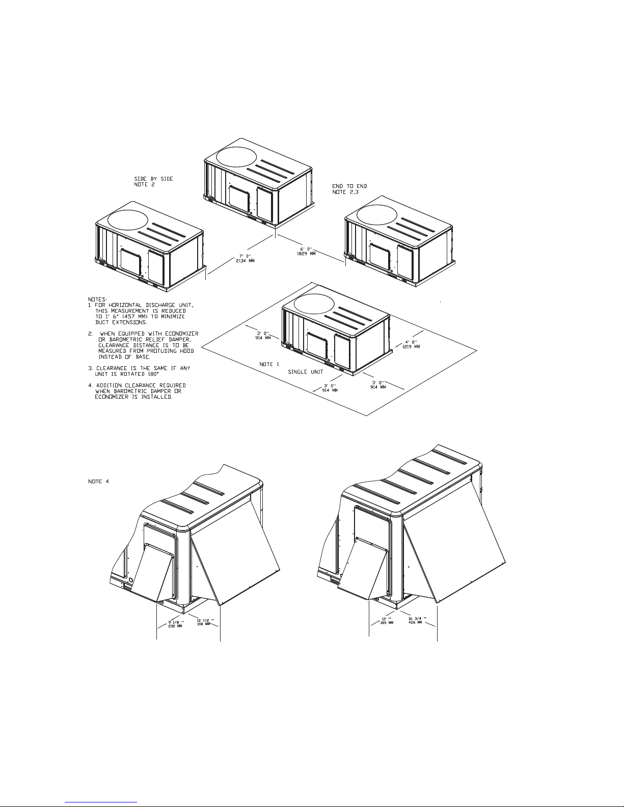
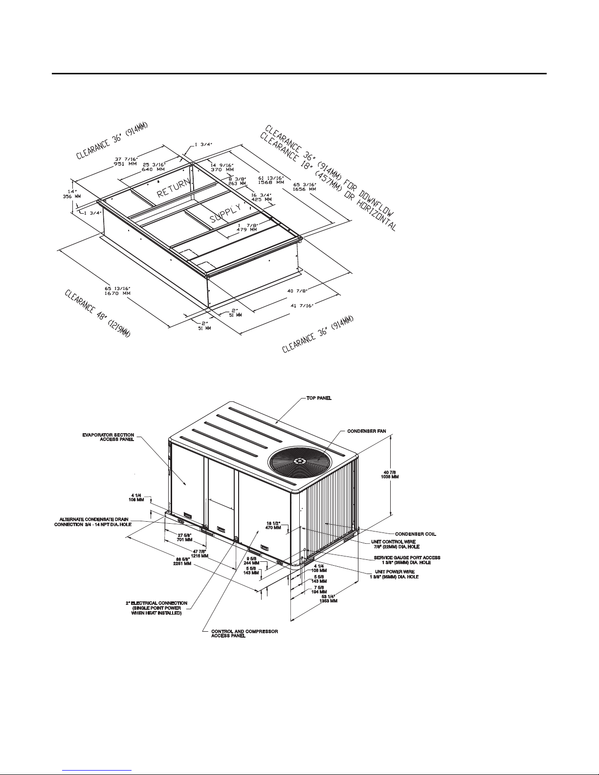
Unit Dimensions
Figure 1. Typical installation clearances for single & multiple unit applications
WSC036-048E Units
12 RT-SVX23G-EN
WSC060-120E Units
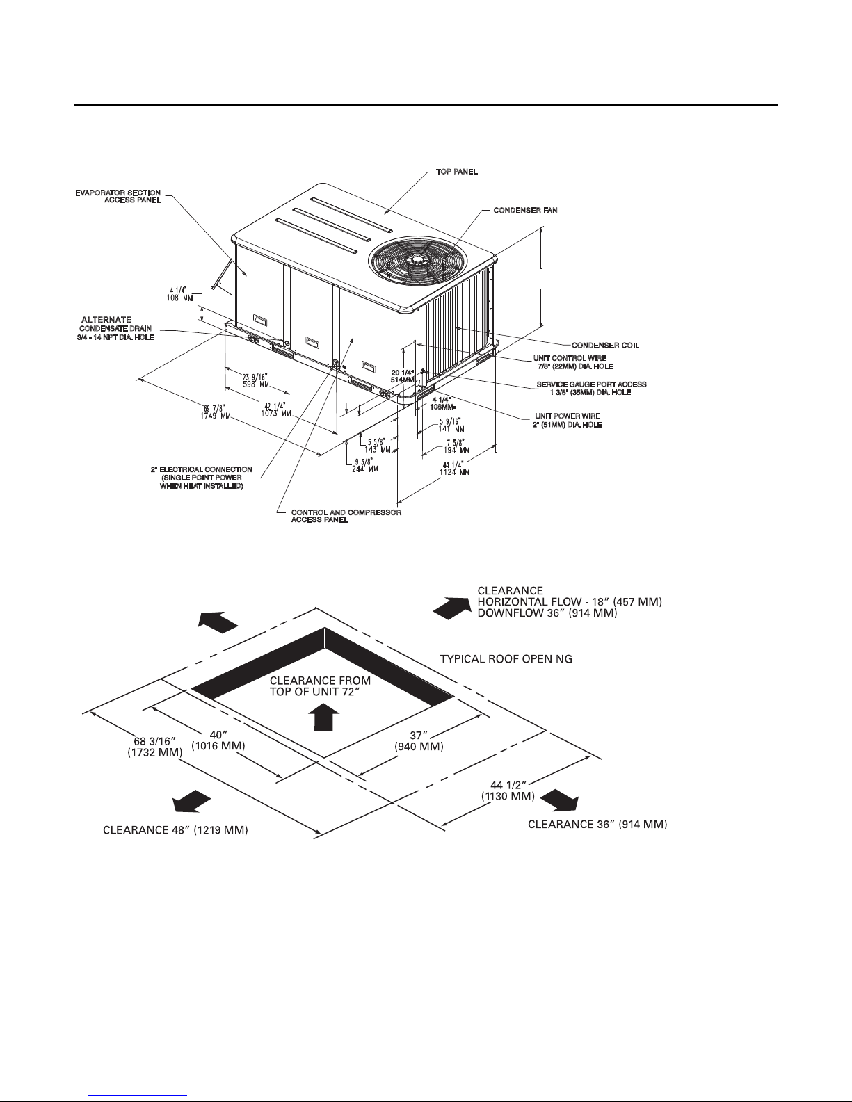
Figure 2. Heat pump - 3-4 ton standard efficiency
Note: All dimensions are in inches/millimeters.
Unit Dimensions
Figure 3. Heat pump - 3-4 ton standard efficiency - unit clearance and roof opening
Note: All dimensions are in inches/millimeters.
CLEARANCE 36” (914 MM)
RT-SVX23G-EN 13
Unit Dimensions
44 MMMM
44 MMMM
1038 MMMM
1053 MMMM
Figure 4. Heat pump - 3-4 ton standard efficiency - roof curb
Note: All dimensions are in inches/millimeters.
44
44
7
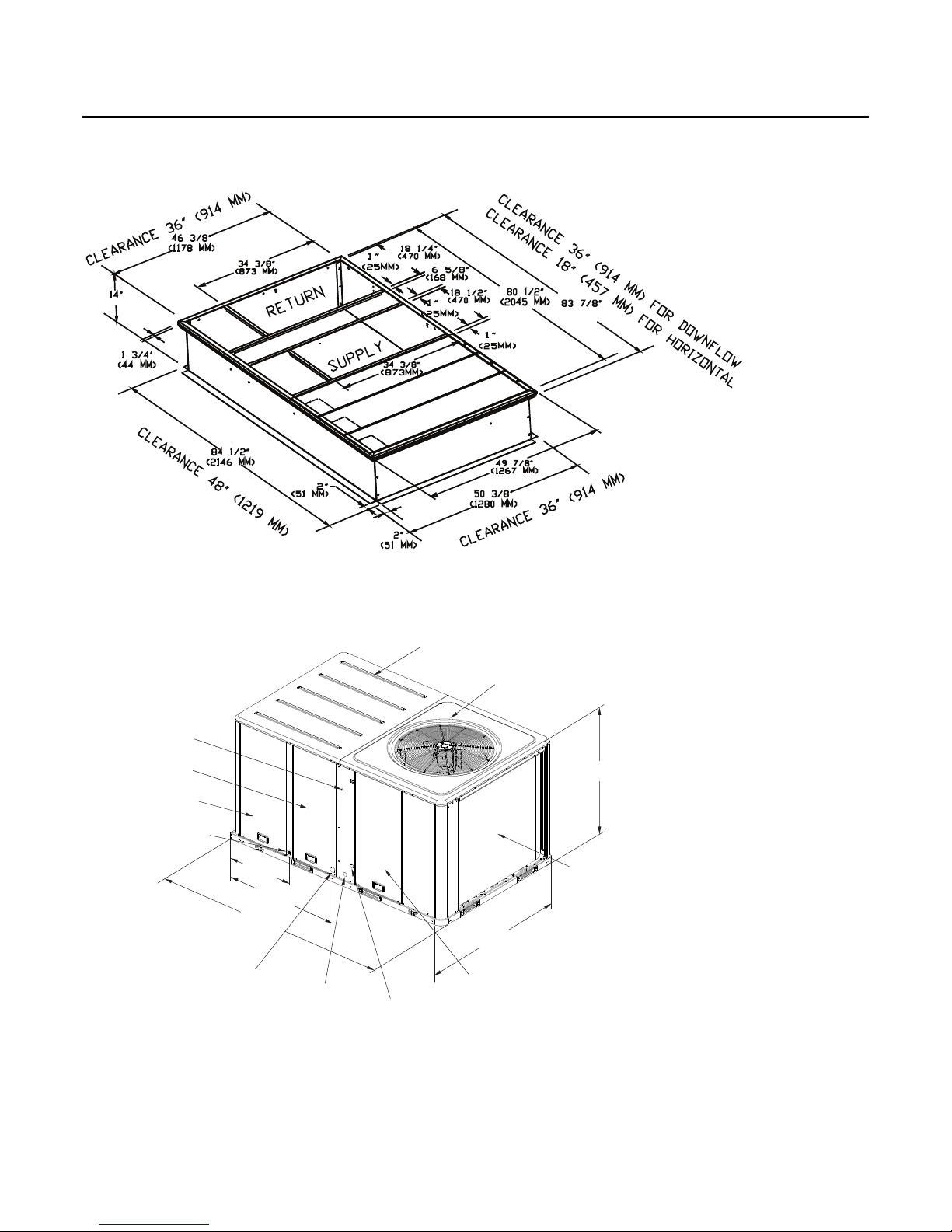
Figure 5. Heat pumps - 5-6 ton standard efficiency
Note: All dimensions are in inches/millimeters.
1038
1053
14 RT-SVX23G-EN
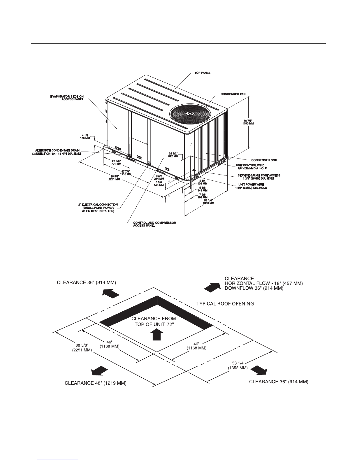
Figure 6. Heat pump - 7½ ton standard efficiency
Note: All dimensions are in inches/millimeters.
Unit Dimensions
Figure 7. Heat pump - 5-7½ ton - unit clearance and roof opening
Note: All dimensions are in inches/millimeters.
RT-SVX23G-EN 15
Unit Dimensions
/8”(
)
Figure 8. Heat pump - 5-7½ ton - roof curb
Note: All dimensions are in inches/millimeters.
(356 MM)
Figure 9. Heat pump - 10 ton standard efficiency
Notes:
1. All dimensions are in inches/millimeters.
2. 2" Electrical Connection: Single Point Power When Heat Installed (WSC Models only.)
INDOOR TOP PANEL
OUTDOOR TOP PANEL
UNIT CONTROL WIRE
22MM
DIA HOLE
7
CONTROL BOX SECTION
ACCESS PANEL
EVAPORATOR SECTION
ACCESS PANEL
ALTERNATE CONDENSATE DRAIN
CONNECTION 3/4-14 NPT DIA.HOLE
(2130 MM)
50 7/8”
1292 MM
27 5/8”
701 MM
47 7/8”
1216 MM
99 11/16”
2” ELECTRICAL CONNECTION
(SINGLE POINT POWER WHEN
HEAT INSTALLED)
2532 MM
UNIT POWER WIRE
1 3/8” (35MM) DIA. HOLE
16 RT-SVX23G-EN
SERVICE GAUGE PORT ACCESS 1
3/8” (35MM) DIA. HOLE
63 3/16”
1605 MM
COMPRESSOR ACCESS PANEL
CONDENSER COIL
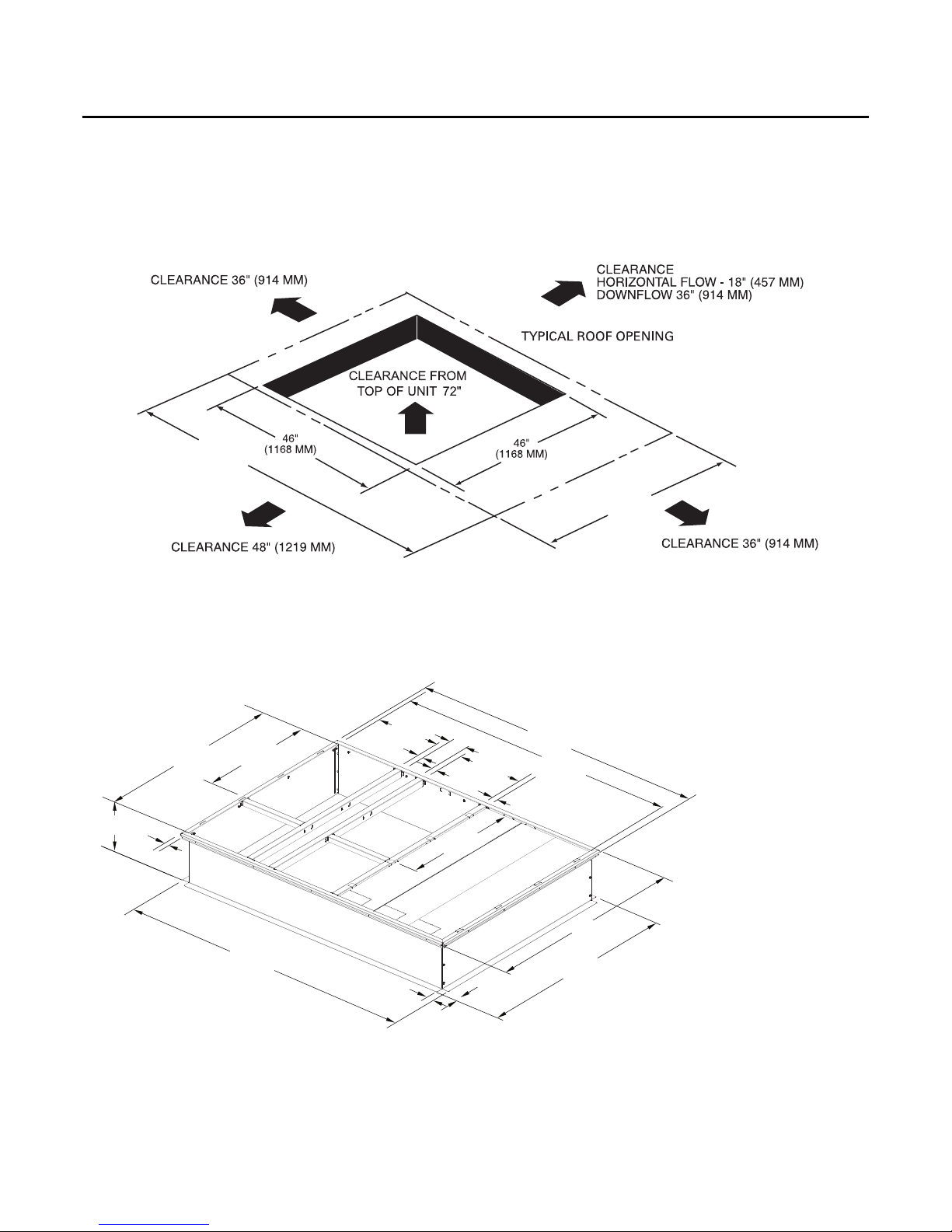
Figure 10. Heat pump - 10 ton standard efficiency - unit clearance and roof opening
(
)
(
)
(
)
(
)
(
)
(
)
(
)
(
)
(
)
Notes:
1. All dimensions are in inches/millimeters.
99 11/16”
(2532 MM)
63 3/16”
(1605 MM)
Unit Dimensions
Figure 11. Heat pump - 10 ton standard efficiency - roof curb
Notes:
1. All dimensions are in inches/millimeters.
18 1/2”
14”
356 MM
13/4”
44 MM
56 3/8”
(1432 MM)
34 3/8”
(873 MM)
84 1/2”
(2146 MM)
25 MM
1”
51 MM
(470 MM)
2”
51 MM
65/8”
168 MM
1”
25 MM
34 3/8”
(873 MM)
2”
CLEARANCE36”(914MM) FOR DOWNFLOW
CLEARANCE 18” (457 MM) FOR HORIZONTAL
83 7/8”
(2130 MM)
18 1/2”
(470 MM)
1”
25 MM
80 1/2”
(2045 MM)
60 3/8”
(1534 MM)
59 7/8”
1521 MM
RT-SVX23G-EN 17
 Loading...